

Page 1
Installation and Operation Manual
AA35-001
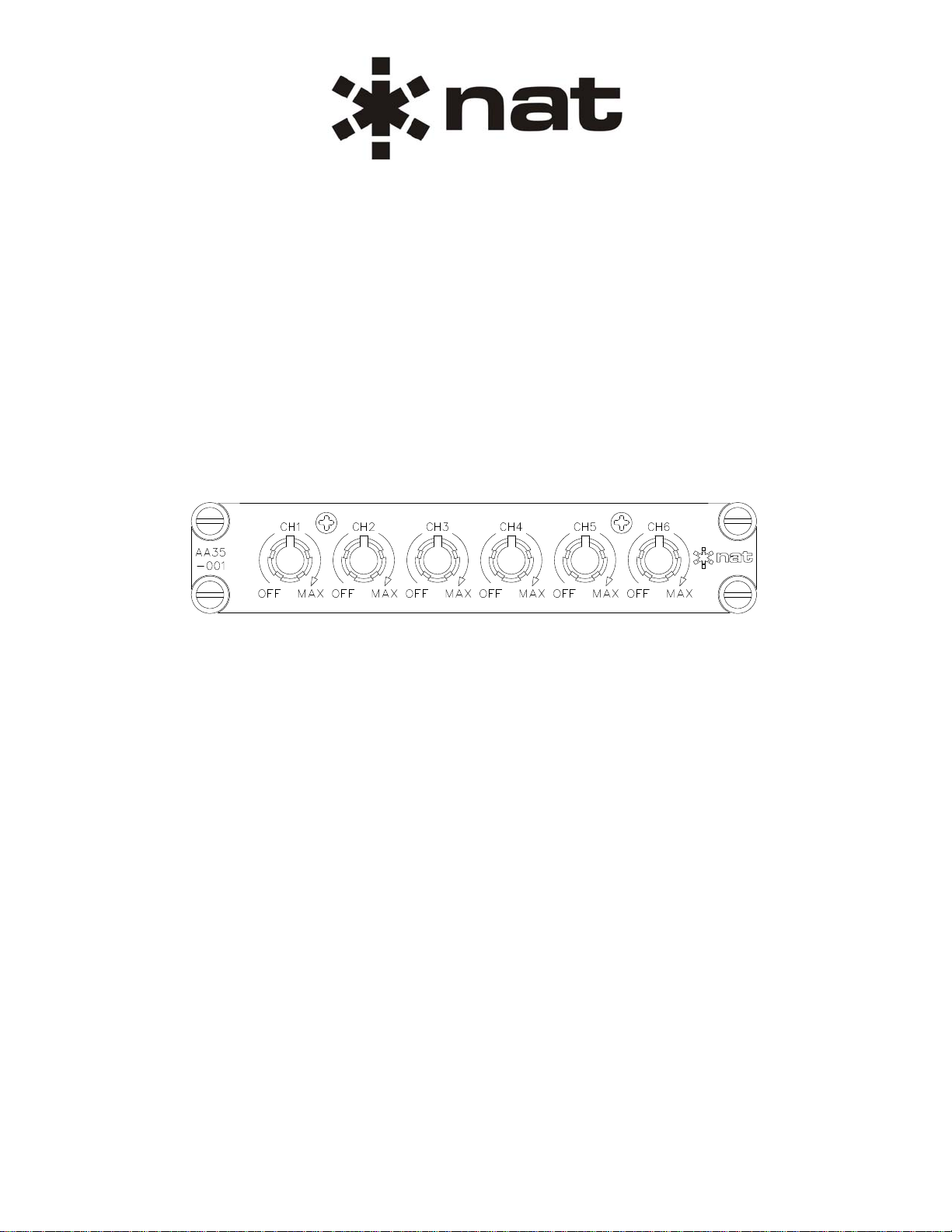
Audio Mixer Panel
SM25
ISSUE 4.01
Northern Airborne Technology Ltd.
1925 Kirschner Road
Kelowna, BC, Canada.
Telephone (250) 763-2232
Facsimile (250) 762-3374
Issued on the authority of Northern Airborne Technology Ltd.
Copyright 2003
V1Y 4N7
Page 2
AA35-001 Audio Mixer Panel
SM25 Installation and Operation Manual
Prepared By: Checked By: Approved By:
The status of this installation and operation manual is controlled by issue shown on the title page. The
status of each section is controlled by revision shown in the footer of each page. All revisions affecting
sections of this manual have been incorporated into the latest issue.
ISSUE/REVISION RECORD
Manual Issue
Number
Section
Revision Number
Revision Description Issue Date
4.01 Section 1 Rev: 1.00
Rewritten in latest format Oct 10, 2008
Section 2 Rev: 1.00
Section 3 Rev: 1.00
4.00 N/A Split Manual format. Nov 20, 2003
Installation and Operation Manual Page ii
ENG-FORM: 820-0114.DOT
CONFIDENTIAL AND PROPRIETARY TO NORTHERN AIR BORNE TECHNOLOGY LTD.
Page 3

AA35-001 Audio Mixer Panel
SM25 Installation and Operation Manual
Table of Contents
Section Title Page
1. Description
1.1 Introduction 1-1
1.2 Product Description 1-1
1.3 Design Features 1-1
1.4 Specifications 1-1
1.4.1 Electrical Specifications 1-1
1.4.2 Physical Specifications 1-2
1.4.3 Environmental Specifications 1-2
1.5 Unit Nomenclature 1-3
2. Installation
2.1 Introduction 2-1
2.2 Unpacking and Inspection 2-1
2.2.1 Warranty 2-1
2.3 Continued Airworthiness 2-1
2.4 Installation Procedures 2-1
2.4.1 Warnings 2-1
2.4.2 Cautions 2-2
2.4.3 Cabling and Wiring 2-2
2.4.4 Post Installation Checks 2-2
2.5 Adjustments and Connections 2-3
2.5.1 8/600 Ω Adjustment 2-3
2.5.2 Input Audio Level Adjustment 2-3
2.5.3 Composite Output Level Adjustment 2-3
2.6 Accessories Required But Not Supplied 2-4
2.7 Installation Drawings 2-4
3. Operation
3.1 Introduction 3-1
3.2 General Information 3-1
3.3 Controls and Indicators 3-1
3.3.1 Channel Controls 3-1
Installation and Operation Manual Page iii
ENG-FORM: 820-0114.DOT
CONFIDENTIAL AND PROPRIETARY TO NORTHERN AIR BORNE TECHNOLOGY LTD.
Page 4

AA35-001 Audio Mixer Panel
SM25 Installation and Operation Manual
Section 1 Description
1.1 Introduction
Information in this section consists of product description, design features and specifications for the
AA35-001 Audio Mixer Panel. All derivative product information shall be contained in the applicable
manual supplement, which may be obtained from NAT as required.
Review all notes, warnings and cautions.
1.2 Product Description
The AA35-001 Audio Mixer Panel is a six channel summing amplifier with independent level control for
each input. It can be used as an expansion panel for existing audio controllers.
The AA35 is also available in remote mount configurations (see Section 1.5)
1.3 Design Features
The AA35-001 Audio Mixer Panel provides six independent channels with differential inputs and balanced
outputs for high common mode noise rejection. Also provided is a composite output. Each channel is
individually adjustable with a 40 dB range. The input audio level is internally selectable by DIP switch to
2.5 or 7 Vrms. Output impedance of each channel is individually selectable via internal jumpers to allow
the connection of an 8 or 600 Ω load.
1.4 Specifications
1.4.1 Electrical Specifications
Input Voltage 27.5 Vdc (nominal)
Input Current 275 mA (nominal)
Lighting 80 mA @ 27.5 Vdc
Input Signals
Channels 6 independent channels
Impedance 4.0 kΩ +/- 10%
Audio level 2.5 or 7 Vrms. Selectable by DIP switch
Circuitry Type: Differential input for high common mode noise rejection.
Coupling: <-40 dB input to input Crosstalk
Section 1 Rev: 1.00 Issue 4 Page 1-1
ENG-FORM: 800-0114.DOT
CONFIDENTIAL AND PROPRIETARY TO NORTHERN AIR BORNE TECHNOLOGY LTD.
Page 5

AA35-001 Audio Mixer Panel
SM25 Installation and Operation Manual
Output Signals
1.4.2 Physical Specifications
Channels 6 inde p e n d ent c h a n n e ls pl u s 1 c o m p o s i t e o u t p u t
Rated level 7.7 Vrms or 100 mW into 600 Ω
1.3 Vrms or 200 mW into 8 Ω
Impedance 20 Ω max
Frequency Response <3 dB from 3 50 to 6000 Hz
Distortion <10% THD @ Rated power output
Circuitry Type: Balanced output for high common mode noise rejection.
Coupling: <-50 dB input to output Crosstalk.
Audio Noise Level Without Si gnal: >60 dB down from rated output level.
Output Regulation at 400% <10% distortion / Δ3 dB max. of rat ed output power.
and 75% of rated load.:
Height 1.12" (28.4 mm)
Depth
5.68" (144.27 mm) overall
4.78" (121.14 mm) behind panel
Width (max) 5.75" (146.05 mm) (faceplate)
Width (box) 4.90" (124.46 mm) (behind panel)
Weight 1.1 lb (500 g)
Mounting Dzus Rail
Faceplate Laser etched acrylic back-lit panel
Material/Finish
Chassis and cover 5052-H32 brushed aluminum with
chromate conversion finish
1.4.3 Environmental Specifications
Temperature:
Operating -45° C to +70° C
Survival -55° C to +85° C
Altitude 35,000 ft. max
Humidity 95%
Vibration/Shock DO-160C, Cat. N/B/M
Section 1 Rev: 1.00 Issue 4 Page 1-2
ENG-FORM: 800-0114.DOT
CONFIDENTIAL AND PROPRIETARY TO NORTHERN AIR BORNE TECHNOLOGY LTD.
Page 6

AA35-001 Audio Mixer Panel
SM25 Installation and Operation Manual
1.5 Unit Nomenclature
These products are included for reference only. For more detailed information on these and other AA35
products, contact the Product Support Department at NAT Ltd.
AA35-001 Dzus mount audio mixer / summing amplifier panel
Provides signal combinations of up to six in / six out or six in / one composite out
2.5 Vrms or 7 Vrms input level
Output 7.7 Vrms or 100 mW/600 Ohm Max
Panel Lighting 28 Vdc (normal)
AA35-100 Remote mount audio mixer / summing amplifier
Provides signal combinations of up to six in / six out or six in / one composite out
2.5 Vrms or 7 Vrms input level
Output 7.7 Vrms or 100 mW/600 Ohm Max
AA35-400 Remote mount audio mixer / summing amplifier for TAWS applications
Provides signal combinations of up to three in / three out or three in / one composite out
2.5 Vrms or 7 Vrms input level
Output 7.7 Vrms or 100 mW/600 Ohm Max
Section 1 ends
Section 1 Rev: 1.00 Issue 4 Page 1-3
ENG-FORM: 800-0114.DOT
CONFIDENTIAL AND PROPRIETARY TO NORTHERN AIR BORNE TECHNOLOGY LTD.
Page 7

AA35-001 Audio Mixer Panel
SM25 Installation and Operation Manual
Section 2 Installation
2.1 Introduction
Information in this section consists of unpacking and inspection procedures, installation procedure s, po stinstallation checks and installation drawings for the AA35-001 Audio Mixer Panel.
Review all notes, warnings and cautions.
2.2 Unpacking and Inspection
Unpack the equipment carefully and locate the warranty card. Inspect the unit visually for damage due to
shipping and report all such claims immediately to the carrier involved. Check that all items listed below
are present before proceeding and report any shortage immediately to your supplier:
- Warranty Card
- Operators Manual
- Certificate of Conformity or Release Certification
2.2.1 Warranty
All Northern Airborne Technology Ltd. products are warranted for 2 years from date of installation by an
authorized NAT dealer, to be free of defects in workmanship or performance. This warranty covers all
materials and labour, but is exclusive of any transport to deliver the defective unit to and from NAT or its
designated warranty repair center, or any labour to remove or re-install the defective unit in the aircraft.
Contact NAT for any questions regarding this warranty, its applicability to your units and/or for return
authorization. NAT is the final arbitrator concerning warranty administration. Units which have been
physically damaged, burned, immersed in water or otherwise abused beyond the scope of normal use will
not be considered for warranty. WARRANTY IS VOID UNLESS THE PRODUCT IS INSTALLED BY AN
AUTHORIZED NAT DEALER. Product for which a warranty card is not returned shall be warranted from
date of manufacture.
2.3 Continued Airworthiness
Maintenance of the AA35-001 Audio Mixer Panel is ‘on condition’ only. Periodic maintenance of this
product is not required.
2.4 Installation Procedures
2.4.1 Warnings
WARNING:
High volume settings can cause hearing damage.
Set the headset volume control to the minimum volume setting prior to
conducting tests, and slowly increase the headset volume to a
comfortable listening level.
Section 2 Rev: 1.00 Issue 4 Page 2-1
ENG-FORM: 805-0117.DOT
CONFIDENTIAL AND PROPRIETARY TO NORTHERN AIR BORNE TECHNOLOGY LTD.
Page 8

AA35-001 Audio Mixer Panel
SM25 Installation and Operation Manual
2.4.2 Cautions
CAUTION:
Do not bundle any lines from this unit with transmitter coax feedlines. Do not
bundle any logic, audio, or DC power lines from this unit with 400 Hz synchro
wiring or AC power lines. Do not position this unit next to any device with a
strong alternating magnetic field such as an inverter, motor or blower, or
significant audio interference will result.
In all installations, use shielded cable exactly as shown, and ground only as
indicated. Significant problems may result from not following these guidelines.
2.4.3 Cabling and Wiring
All wire shall be selected in accordance with the original aircraft manufacturer's Maintenance Instructions
or AC43.13-1B Change 1, Paragraphs 11-76 through 11-78. Unshielded wire types shall qualify to
MIL-W-22759 as specified in AC43.13-1B Change 1, Paragraphs 11-85, 11-86, and listed in Table 11-11.
For shielded wire applications, use Tefzel MIL-C-27500 shielded wire with solde r sleeve s (fo r shield
terminations) to make the most compact and easily terminated interconnect. Follow the connector map in
Section 2.7 as required.
Allow 3" from the end of the shielded wiring to the shield termination to allow the connector hood to be
easily installed. Reference the interconnect drawing in Section 2.7 for shield termination details. Note that
the hood is a "clamshell" hood, and is installed after the wiring is complete. Aircraft harnessing shall
permit the unit to be removed from the panel for easy access to all side adjustments. Do NOT mount the
unit until all adjustments have been performed.
Maintain wire segregation and route wiring in accordance with the original aircraft manufacturers
Maintenance Instructions.
Unless otherwise noted, all wiring shall be a minimum of 22 AWG, except power and ground lines, which
shall be a minimum of 20 AWG. Refer to the Interconnect drawing for additional specifications. Check that
the ground connection is clean and well secured, and that it shares no path with any electrically noisy
aircraft accessories such as blowers, turn and bank instruments or similar loads. Power to this unit must
be supplied from a separate circuit breaker or fuse (fast blow), and not attached to any other circuit
breaker without additional protection. Verify that the selected circuit breaker size and wire gauge are
adequate for the installation using the techniques specified in AC43.13-1B Change 1, Paragraphs 11-47
through 11-51 and 11-66 through 11-69.
2.4.4 Post Installation Checks
2.4.4.1 Voltage/Resistance Ch ecks
Do not attach the AA35-001 until the following conditions are met.
Check the following:
a) J1 pins <1> and <2> for +28 Vdc relative to ground.
b) J1 pins <20> and <21> for continuity to ground (below 0.5Ω).
Section 2 Rev: 1.00 Issue 4 Page 2-2
ENG-FORM: 805-0117.DOT
CONFIDENTIAL AND PROPRIETARY TO NORTHERN AIR BORNE TECHNOLOGY LTD.
Page 9

AA35-001 Audio Mixer Panel
SM25 Installation and Operation Manual
2.4.4.2 Power On Checks
Power up the aircraft’s systems and confirm normal operation of all functions of the AA35-001. Refer to
Section 3 (Operation) for specific operational details.
a) Check for the correct audio output on each channel.
Upon satisfactory completion of all performance checks, make all required log book entries, electrical
load, weight and balance amendments and other documentation as required by your local regulatory
agency before releasing the aircraft for service.
2.5 Adjustments and Connections
These procedures should be performed by a qualified service
technician, at an ESD safe workstation only. Failure to adhere to this
warning could cause injury to personnel and/or damage to equipment.
2.5.1 8/600 Ω Adjustment
WARNING:
Remove the cover from the AA35 and locate the seven 8/600 Ω adjustment jumpers (JP1 thru JP7).
Each jumper controls one of the six independent channels or the Composite Output (refer to table 1).
When the jumper is connected across pins A and B, the channel is set to operate with an 8 Ω load
connected. When connected across B and C (the default setting), the channel is set to operate with a
600 Ω load connected. Refer to the Maintenance Section of this Manual for complete details.
Jumper Channel
JP1 Channel 1
JP2 Channel 2
JP3 Channel 3
JP4 Channel 4
JP5 Channel 5
JP6 Channel 6
JP7 Composite Output
Table 1: 8/600 Ω Jumpers
2.5.2 Input Audio Level Adjustment
The input audio level adjustment consists of six DIP switches (S1 thru S6), accessible from the right hand
side of the AA35. Each switch controls one of the six independent channels. The switch number reflects
the channel being controlled (e.g. S1 controls channel 1 and S4 controls cha nnel 4). Each level can be
set to allow a 2.5 V (switch up) or a 7.5 V (switch down) input.
2.5.3 Composite Output Level Adjustment
The output level of the composite audio can be adjusted from the right hand side of the AA35. Rotating
the trim potentiometer from fully counter clockwise to clockwise will increase the output over a 40 dB
range.
Section 2 Rev: 1.00 Issue 4 Page 2-3
ENG-FORM: 805-0117.DOT
CONFIDENTIAL AND PROPRIETARY TO NORTHERN AIR BORNE TECHNOLOGY LTD.
Page 10

AA35-001 Audio Mixer Panel
SM25 Installation and Operation Manual
2.6 Accessories Required But Not Supplied
A crimp installation kit p/n AA35-IKC-1 (NAT Part No. D37SV-IKC) is required to complete the installation.
The kit consists of the following:
D37SV-IKC
Quantity Description NAT Part #
1 D-min 37 Socket Housing 20-21-037
37 MS Crimp Socket 20-26-901
1 37 Pin JVL Hood/Locklever 20-29-370
2.7 Installation Drawings
DOCUMENT REV. DESCRIPTION TYPE SERIAL NO.
AA35-001
AA35\001\403-0 1.00 Audio Mixer Panel Interconnect All
AA35\001\405-0 1.00 Audio Mixer Panel Connector Map All
AA35\001\905-0 1.00 Audio Mixer Panel Faceplate Up to 1186
AA35\001\905-0 1.10 Audio Mixer Panel Faceplate 1187 and up
AA35\001\922-0 1.00 Audio Mixer Panel Mech. Installation Up to 1186
AA35\001\922-0 1.10 Audio Mixer Panel Mech. Installation 1187 and up
Section 2 ends following the above documents
Section 2 Rev: 1.00 Issue 4 Page 2-4
ENG-FORM: 805-0117.DOT
CONFIDENTIAL AND PROPRIETARY TO NORTHERN AIR BORNE TECHNOLOGY LTD.
Page 11

Confidential and Proprietary to NAT
Page 12

Confidential and Proprietary to NAT
Page 13

Confidential and Proprietary to NAT
Page 14

Confidential and Proprietary to NAT
Page 15

Confidential and Proprietary to NAT
Page 16

Confidential and Proprietary to NAT
Page 17

AA35-001 Audio Mixer Panel
SM25 Installation and Operation Manual
Section 3 Operation
3.1 Introduction
Information in this section consists of the functional and operational procedures for the AA35-001 Audio
Mixer Panel.
3.2 General Information
The AA35-001 Audio Mixer Panel is a six channel summing amplifier with independent level control for
each input. It can be used as an expansion panel for existing audio controllers.
The AA35-001 Audio Mixer Panel provides six independent channels with differential inputs and balanced
outputs for high common mode noise rejection. Also provided is a composite output. Each channel is
individually adjustable with a 40 dB range. The input audio level is internally selectable by DIP switch to
2.5 or 7 Vrms. Output impedance of each channel is individually selectable via internal jumpers to allow
the connection of an 8 or 600 Ω load.
3.3 Controls and Indicators
3.3.1 Channel Controls
The AA35-001 has six front panel rotary controls. Each one controls the volume level of an independent
channel. With the control fully counterclockwise it is in the OFF detent position and no audio will be heard
on the headset for that channel. Rotating the control clockwise past the detent will turn the channel on.
The volume will increase as the control is rotated clockwise and decrease as it is rotated
counterclockwise.
WARNING:
High volume settings can cause hearing damage.
Set the headset volume control to the minimum volume setting, and
slowly increase the headset volume to a comfortable listening level.
Section 3 ends
Section 3 Rev: 1.00 Issue 4 Page 3-1
ENG-FORM: 806-0112.DOT
CONFIDENTIAL AND PROPRIETARY TO NORTHERN AIR BORNE TECHNOLOGY LTD.
 Loading...