

Page 1
Installation and Operation Manual
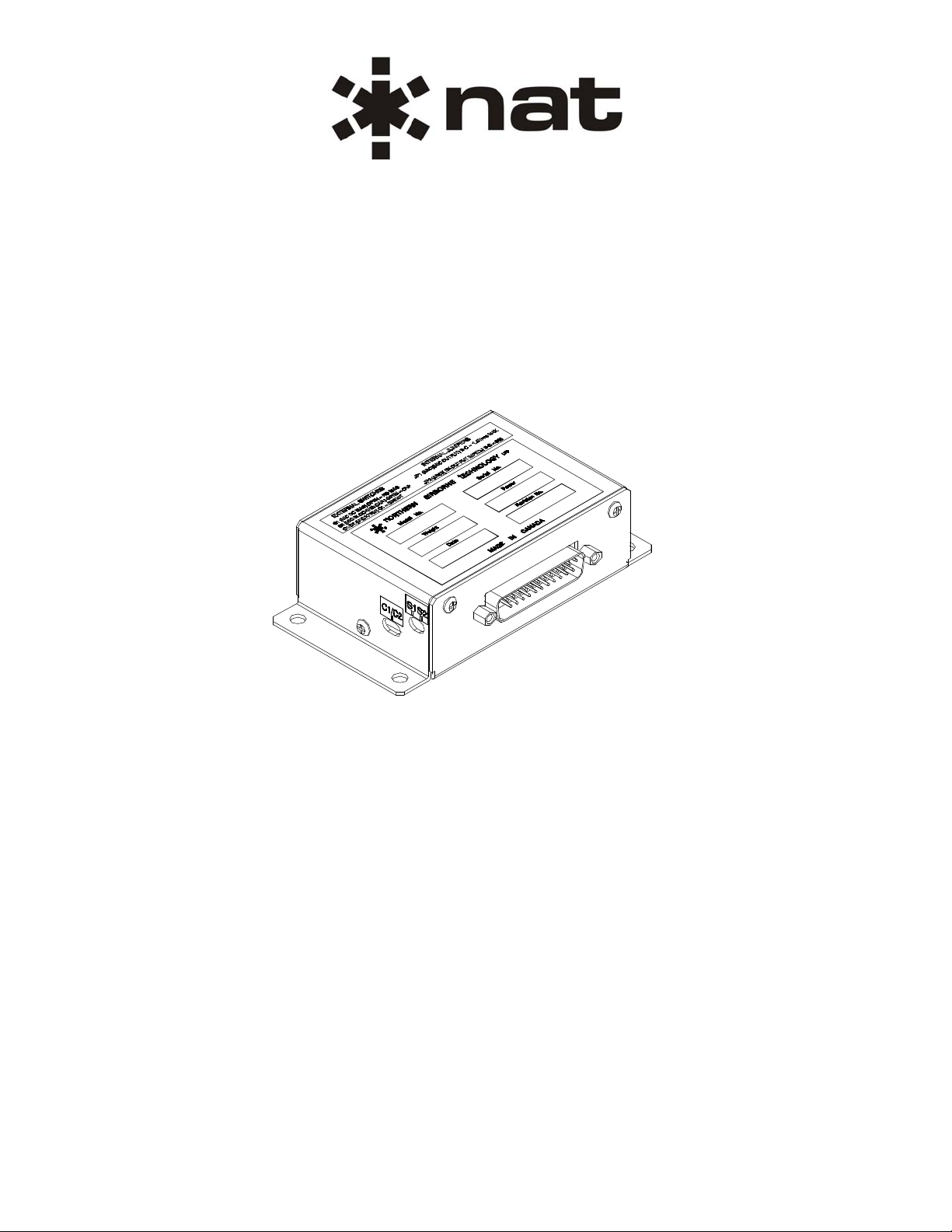
AA34 Series
Universal Radio Interface
SM36
ISSUE 4.01
Northern Airborne Technology Ltd.
1925 Kirschner Road
Kelowna, BC, Canada.
V1Y 4N7
Telephone (250) 763-2232
Facsimile (250) 762-3374
Issued on the authority of Northern Airborne Technology Ltd.
Copyright 2003
Page 2

AA34 Series Universal Radio Interface
SM36 Installation and Operation Manual
Prepared By: Checked By: Certification: Approved By:
The status of this installation and operation manual is controlled by issue shown on the title page. The
status of each section is controlled by revision shown in the footer of each page. All revisions affecting
sections of this manual have been incorporated into the latest issue.
ISSUE/REVISION RECORD
Manual Issue
Number
Section
Revision Number
Revision Description Issue Date
4.01 Section 1 Rev: 1.00
Section 2 Rev: 1.00
Section 3 Rev: 1.00
4.00 n/a Initial Release Nov 10, 2003
Rewritten in latest format Jan 11, 2010
Installation and Operation Manual Page ii
ENG-FORM: 820-0115.DOT
CONFIDENTIAL AND PROPRIETARY TO NORTHERN AIR BORNE TECHNOLOGY LTD.
Page 3

AA34 Series Universal Radio Interface
SM36 Installation and Operation Manual
Table of Contents
Section Title Page
1. Description
1.1 Introduction 1-1
1.2 Product Description 1-1
1.3 Design Features 1-1
1.4 Specifications 1-1
1.4.1 Electrical Specifications 1-1
1.4.2 Physical Specifications 1-2
1.4.3 Environmental Specifications 1-2
1.4.4 Product Approval 1-2
1.5 Unit Nomenclature 1-3
2. Installation
2.1 Introduction 2-1
2.2 Unpacking and Inspection 2-1
2.2.1 Warranty 2-1
2.3 Continued Airworthiness 2-1
2.4 Installation Procedures 2-1
2.4.1 Warnings 2-2
2.4.2 Cautions 2-2
2.4.3 Cabling and Wiring 2-2
2.4.4 Post-Installation Checks 2-3
2.5 Adjustments and Connections 2-3
2.5.1 External Adjustments 2-3
2.5.2 Internal Adjustments (AA34-200 only) 2-5
2.5.3 Internal Adjustments (AA34-300 and AA34-301 only) 2-6
2.6 Accessories Required But Not Supplied 2-7
2.7 Installation Drawings 2-7
3. Operation
3.1 Introduction 3-1
3.2 General Information 3-1
Installation and Operation Manual Page iii
ENG-FORM: 820-0115.DOT
CONFIDENTIAL AND PROPRIETARY TO NORTHERN AIRBORNE TECHNOLOGY LTD.
Page 4
AA34 Series Universal Radio Interface
SM36 Installation and Operation Manual
Section 1 Description
1.1 Introduction
Information in this section consists of product description, design features and specifications for the
AA34-200, AA34-300 and AA34-301 Universal Radio Interfaces. All other derivative product information
shall be contained in the applicable manual supplement, which may be obtained from Northern Airborne
Technology Ltd. as required.
Review all notes, warnings and cautions.
1.2 Product Description
The AA34 Universal Radio Interface will handle the interface and switching requirements of mobile or CB
radio systems when integrated into an aircraft audio system.
1.3 Design Features
The AA34 Universal Radio Interface units provide microphone excitation; relay keying, and sidetone
generation, all fully isolated from airframe ground.
1.4 Specifications
1.4.1 Electrical Specifications
Input Power +13.8 Vdc ± 10% or 27.5 Vdc ± 10% (Selected by
(AA34-200) 160 mA
(AA34-300\301) 70 mA
Input Signals
Mic 250 mVrms @ 150 Ω ±10%
Audio 2.5 Vrms @ 600 Ω ±10%
Output Signals
Mic (AA34-200) Approx. 225 mVrms max into 150 Ω
(AA34-300\301) Adjustable to 1.5 Vrms max into 600 Ω or 178 mVrms
Audio (AA34-200) 200 mW into 150 or 600 Ω nominal
(AA34-300\301) 100 mW into 8 or 600 Ω nominal
*Frequency Response <3 dB from 350 Hz to 6 kHz
*Distortion <10% @ rated output
*Noise level without signal >50 dB down from rated output
appropriate pin)
into 8 Ω
Section 1 Rev: 1.00 Issue 4 Page 1-1
ENG-FORM: 800-0116.DOT
CONFIDENTIAL AND PROPRIETARY TO NORTHERN AIR BORNE TECHNOLOGY LTD.
Page 5

AA34 Series Universal Radio Interface
SM36 Installation and Operation Manual
*Regulation <10% variation from 75% to 400% of load
* The s e s i g na l s ha v e be e n de t e rm i n ed f or t he AA34-300 and AA34-301 only
1.4.2 Physical Specifications
Height 1.30 inches (33.0 mm) max
Depth 2.71 inches (68.8 mm) max excluding connector
Width 4.54 inches (115.3 mm) max
Weight
AA34-200 0.63 lb (285 g) max
AA34-300\301 0.40 lb (180 g ) max
Mounting Bulkhead mount with four 10-32 screws
Material/Finish 5052-H32 brushed aluminum chassis and cover with
Connectors AA34-200 25 pin male D-sub
AA34-300\301 25 pin male filtered D-sub
conversion finish
1.4.3 Environmental Specifications
Temperature
-20 C to +55 C (Operating)
-55 C to +85 C (Survival)
Altitude
AA34-200 15,000 ft (tested to 25,000 ft)
AA34-300\301 35,000 ft
Humidity 95% non-condensing
Shock 6g (any axis)
Vibration (AA34-300) RTCA/DO-160C categories (B,M,N)
Qualification of the AA34-300 Universal Radio Interface was completed in accordance with
DO-160C Env. Cat. C1-BA[BMN]XXXXXXABABATAXXX
Qualification of the AA34-301 Universal Radio Interface was completed in accordance with
DO-160C Env. Cat. C1-BA[MN]XXXXXXABABATAXXX
Note: Refer to Environmental Qualification Form located in Section 2 of this Manual for complete details
of the environmental categories.
1.4.4 Product Approval
FAA: TSO-C50c (RTCA/DO-170 Class II, RTCA/DO-160C)
Applicable to AA34-300 units s/n 20,001 and up
Section 1 Rev: 1.00 Issue 4 Page 1-2
ENG-FORM: 800-0116.DOT
CONFIDENTIAL AND PROPRIETARY TO NORTHERN AIR BORNE TECHNOLOGY LTD.
Page 6

AA34 Series Universal Radio Interface
SM36 Installation and Operation Manual
1.5 Unit Nomenclature
Model Description
AA34-200 Mobile/FM radio interface.
Provides floating key lines.
Internal RX & Sidetone Amplifier.
Provides floating audio lines in and out.
Internal mic exciter with adjustable output.
Internally selectable functions and levels.
AA34-300 Mobile/FM radio interface.
Provides floating key lines.
Internal RX, Sidetone and Microphone Amplifiers.
Provides floating audio lines in and out.
Internal mic exciter with adjustable output.
Internally selectable functions and levels.
Designed to meet the requirements of TSO C50c.
AA34-301 Mobile/FM radio interface.
Provides floating key lines.
Internal RX & Sidetone Amplifier.
Provides floating audio lines in and out.
Internal mic exciter with adjustable output.
Internally selectable functions and levels.
External on/off control of mic output.
Designed to meet the requirements of TSO C50c.
Section 1 ends
Section 1 Rev: 1.00 Issue 4 Page 1-3
ENG-FORM: 800-0116.DOT
CONFIDENTIAL AND PROPRIETARY TO NORTHERN AIR BORNE TECHNOLOGY LTD.
Page 7
AA34 Series Universal Radio Interface
SM36 Installation and Operation Manual
Section 2 Installation
2.1 Introduction
Information in this section consists of unpacking and inspection procedures, installation procedures,
post-installation checks and installation drawings for the AA34 Series Universal Radio Interface.
Review all notes, warnings and cautions.
2.2 Unpacking and Inspection
Unpack the equipment carefully and locate the warranty card. Inspect the unit visually for damage due to
shipping and report all such claims immediately to the carrier involved. Check that all items listed below
are present before proceeding and report any shortage immediately to your supplier:
- Warranty Card
- Certificate of Conformity or Release Certification
2.2.1 Warranty
All Northern Airborne Technology Ltd. products are warranted for 2 years from date of installation by an
authorized Northern Airborne Technology Ltd. dealer, to be free of defects in workmanship or
performance. This warranty covers all materials and labour, but is exclusive of any transport to deliver the
defective unit to and from Northern Airborne Technology Ltd. or its designated warranty repair center, or
any labour to remove or re-install the defective unit in the aircraft. Contact Northern Airborne Technology
Ltd. for any questions regarding this warranty, its applicability to your units and/or for return authorization.
Northern Airborne Technology Ltd. is the final arbitrator concerning warranty administration. Units which
have been physically damaged, burned, immersed in water or otherwise abused beyond the scope of
normal use will not be considered for warranty. WARRANTY IS VOID UNLESS THE PRODUCT IS
INSTALLED BY AN AUTHORIZED NORTHERN AIRBORNE TECHNOLOGY LTD. DEALER. Product
for which a warranty card is not returned shall be warranted from date of manufacture.
2.3 Continued Airworthiness
Maintenance of the AA34 Series Universal Radio Interface is ‘on condition’ only. Periodic maintenance of
this product is not required.
2.4 Installation Procedures
Installation Notice
This product must be installed in accordance with the installation instructions provided in the latest issue
of this Installation and Operation Manual. Check the Publication Index at www.northernairborne.com for
the issue status of the manual. The latest issue of the manual may be downloaded from the same
website. All risk associated with installation of this product contrary to these instructions shall be the
responsibility of the installing agency.
Section 2 Rev: 1.00 Issue 4 Page 2-1
ENG-FORM: 805-0121.DOT
CONFIDENTIAL AND PROPRIETARY TO NORTHERN AIR BORNE TECHNOLOGY LTD.
Page 8
2.4.1 Warnings
N/A
2.4.2 Cautions
Do not bundle any lines from this unit with transmitter coax lines. Do not
bundle any logic, audio, or DC power lines from this unit with 400 Hz synchro
wiring or AC power lines. Do not position this unit next to any device with a
strong alternating magnetic field such as an inverter, motor or blower, or
significant audio interference will result.
In all installations, use shielded cable exactly as shown, and ground as
indicated. Significant problems may result from not following these
guidelines.
Incorrect wiring and shielding, can se riously degrad e audio install ations and result
in abnormal cross-talk, hum and ground-loop noise. Be especially careful with all
microphone wiring, as these lines can carry the lowest level signals in the aircraft.
AA34 Series Universal Radio Interface
SM36 Installation and Operation Manual
CAUTION:
2.4.3 Cabling and Wiring
All wire shall be selected in accordance with the original aircraft manufacturer's Maintenance Instructions
or AC43.13-1B Change 1, Paragraphs 11-76 through 11-78. Unshielded wire types shall qualify to
MIL-W-22759 as specified in AC43.13-1B Change 1, Paragraphs 11-85, 11-86, and listed in Table 11-11.
For shielded wire applications, use Tefzel MIL-C-27500 shielded wire with solde r sleeve s (fo r shield
terminations) to make the most compact and easily terminated interconnect. Follow the interconnect
drawing in Section 2.7 as required.
Allow 3" from the end of the shielded wiring to the shield termination to allow the connector hood to be
easily installed. Refer to the interconnect drawing in Section 2.7 for shield termination details. Note that
the hood is a "clamshell" hood, and is installed after the wiring is complete.
Maintain wire segregation and route wiring in accordance with the original aircraft manufacturers
Maintenance Instructions.
Unless otherwise noted, all wiring shall be a minimum of 22 AWG, except power and ground lines, which
shall be a minimum of 20 AWG. Reference the Interconnect drawing for additional specifications. Check
that the ground connection is clean and well secured, and that it shares no path with any electrically noisy
aircraft accessories such as blowers, turn and bank instruments or similar loads. Power to this unit must
be supplied from a separate circuit breaker or fuse (fast blow), and not attached to any other circuit
breaker without additional protection. Verify that the selected circuit breaker size and wire gauge are
adequate for the installation using the techniques specified in AC43.13-1B Change 1, Paragraphs 11-47
through 11-51 and 11-66 through 11-69.
Section 2 Rev: 1.00 Issue 4 Page 2-2
ENG-FORM: 805-0121.DOT
CONFIDENTIAL AND PROPRIETARY TO NORTHERN AIR BORNE TECHNOLOGY LTD.
Page 9

AA34 Series Universal Radio Interface
SM36 Installation and Operation Manual
2.4.4 Post-Installation Checks
2.4.4.1 Voltage/Resistance Checks
Do not attach the AA34 until the following conditions are met.
Check the following:
a) (AA34-200, AA34-300 and AA34-301) P 101 pin <1> for +28 Vdc relative to ground or P101 pin
b) (AA34-200) P101 pins <14> <15> and <23> for continuity to ground (below 0.5 Ω).
c) (AA34-300\301) P101 pins <8> <14> <15> <20> <21> and <23> for continuity to ground (below 0.5 Ω).
<2> for +14 Vdc relative to ground.
2.4.4.2 Power On Checks
Power up the aircraft’s systems and confirm normal operation of all functions of the AA34. Verify normal
operation of all radio functions. Refer to the manual supplied with the mobile radio for specific operation
details.
a) To verify proper operation, all functions and levels shall be checked in-flight.
b) Check preset adjustments are completed before aircraft departure.
Upon satisfactory completion of all performance checks, make all required log book entries, electrical
load, weight and balance amendments and other documentation as required by your local regulatory
agency before releasing the aircraft for service.
2.5 Adjustments and Connections
The AA34 permits many possi ble int erface s. To preven t loss of co mmunic ations, en sure that a ny repla cement
unit is configured exactly the sam e as the on e it is repl acing.
2.5.1 External Adjustments
The unit is shipped from the factory with all external adjustments set to the normal test levels. Once
installed in the aircraft, it may be desirable to change some of these settings to best suit the local
operating environment. The external adjustments are accessible through the left side and rear of the unit.
Section 2 Rev: 1.00 Issue 4 Page 2-3
ENG-FORM: 805-0121.DOT
CONFIDENTIAL AND PROPRIETARY TO NORTHERN AIR BORNE TECHNOLOGY LTD.
Page 10

AA34 Series Universal Radio Interface
SM36 Installation and Operation Manual
2.5.1.1 Rear Adjustments
The rear adjustments are potentiometers, accessed through holes in the cover. Rotating a potentiometer
clockwise (cw) will increase the level, and rotating it counterclockwise (ccw) will reduce the level.
RX LEVEL MIC LEVEL S/T LEVEL
RX LEVEL
MIC LEVEL
S/T LEVEL
Adjusts the signal level of the incoming radio audio.
Adjusts the signal level of the mic output.
Adjusts the signal level of the sidetone.
2.5.1.2 Left side Adjustments
Switches S1 and S2
S1
Provides mic bias to the MIC IN line when closed (default). Open if an external
mic bias is present.
S2
S1 and S2
shown in
Bypass switch for blocking capacitor in mic out circuit. 'Closed' when bias from
the connected radio will be used for mic excitation. 'Open' (default setting) when
internal bias is used or if there are any concerns about DC interaction between
the AA34 and the connected radio.
OPEN
position
Switch C1/C2
This switch determines whether the mic input is amplified. The C1 position provides a di rect mic path
from input to output. The C2 (default) position switches in the amplifier.
AA34-200 only
Switch shown with
C2 Selected
AA34-300 and -301 only
Switch shown
with C2 Selected
The C1/C2 switch on the AA34-200 units is a rocker
switch with the C1 position to the rear of the access
hole, and the C2 position at the front.
The C1/C2 switch on the AA34-300 and -301 units is a
slide switch with the C1 position to the left of the
access hole and the C2 position to the right.
Note: If S1 is CLOSED (mic excited by the AA34), and the transformer isolation is NOT used (C1), the
blocking capacitor should be used (S2 OPEN) if the radio’s input circuitry is unknown. This will
prevent any unwanted interaction with DC present at the radio. The DC blocking capacitor is
connected right at the mic output from the AA34, and is used whenever there may be a problem
with DC present at the radio. This capacitor can be used with or without microphone transformer
isolation, which is used to float the microphone from ground.
Section 2 Rev: 1.00 Issue 4 Page 2-4
ENG-FORM: 805-0121.DOT
CONFIDENTIAL AND PROPRIETARY TO NORTHERN AIR BORNE TECHNOLOGY LTD.
Page 11

AA34 Series Universal Radio Interface
c
t
t
r
r
Sid
A
A
SM36 Installation and Operation Manual
2.5.2 Internal Adjustments (AA34-200 only)
CAUTION:
The AA34 Series Universal Radio Interface contains static sensitive devices.
Proper ESD handling procedures must be followed to prevent damage to the unit.
C1/C 2: Mi
Isolation/ Direc
Switch
S1: Mic
DC Bias
S2: Mic Outpu
Blocking
Capacito
RX High Gain
Jumpe
etone Level
Adjustment
C1
OPEN
S1 S2
Mic Output Level
D E
RX Output Impedance Jumper
(normally soldered F-G)
Adjustment
-B-C M ic
Output Jumper
RX Level
djustment
2.5.2.1 30/200 mV Mic Output Level Adjustment
Remove the cover from the AA34-200 and locate the Mic Output jumper. When the jumper is connected
across pins A and B, the unit level is set at 200 mV. When connected across B and C, the unit level is set
to 30 mV. (The default setting is A – B).
2.5.2.2 RX Gain Adjustment
Remove the cover from the AA34-200 and locate the RX Gain jumper. When the jumper is connected
across pins D and E, the unit is set to operate at high gain. When not connected, the unit is set to
operate at low gain (default setting).
2.5.2.3 RX Output Impedance Adjustment
Remove the cover from the AA34-200 and locate the RX Output Impedance jumper. The factory default
is 600 Ω (jumper soldered across F and G). If connected across G and H, the unit is set to 150 Ω.
Section 2 Rev: 1.00 Issue 4 Page 2-5
ENG-FORM: 805-0121.DOT
CONFIDENTIAL AND PROPRIETARY TO NORTHERN AIR BORNE TECHNOLOGY LTD.
Page 12

p
r
AA34 Series Universal Radio Interface
SM36 Installation and Operation Manual
2.5.3 Internal Adjustments (AA34-300 and AA34-301 only)
CAUTION:
The AA34 Series Universal Radio Interface contains static sensitive devices.
Proper ESD handling procedures must be followed to prevent damage to the unit.
Sidetone Level
Adjustment
Audio
Output
Jumpe
Mic Output Level
Adjustment
Mic Output
Jum
er
RX Level
Adjustment
C1/C2 Mic
Isolation/Direct
Switch
S1 S2
S1 Mic DC Bias
S2 Mic Output Blockin g
2.5.3.1 8/600 Ω Audio Output Impedance Adjustment
Remove the cover from the AA34 and locate the 8/600 Ω adjustment jumper JP2. When the jumper is
connected across pins A and B, the unit is set to operate with an 8 Ω load connected. When connected
across B and C, the unit is set to operate with a 600 Ω load connected. (The default setting is B – C).
2.5.3.2 8/150 Ω Mic Output Impedance Adjustment
Remove the cover from the AA34 and locate the 8/150 Ω adjustment jumper JP1. When the jumper is
connected across pins A and B, the unit is set to operate with an 8 Ω load connected. When connected
across B and C, the unit is set to operate with a 150 Ω load connected (The default setting is B – C).
Section 2 Rev: 1.00 Issue 4 Page 2-6
ENG-FORM: 805-0121.DOT
CONFIDENTIAL AND PROPRIETARY TO NORTHERN AIR BORNE TECHNOLOGY LTD.
Page 13

AA34 Series Universal Radio Interface
SM36 Installation and Operation Manual
2.6 Accessories Required But Not Supplied
Installation kit p/n AA34-IKC (crimp) is required to complete the installation. The kit consists of the
following:
AA34-IKC 25 Pin D-min Female Crimp Kit (NAT Part No D25SL-IKC)
Quantity Description NAT Part No.
1 D-min 25 Socket Housing 20-21-025
25 MS Crimp Socket 20-26-901
1* Jack Screw Set 20-27-002
1* Lock Clip Set 20-27-004
1 25 Pin Connector Hood 20-29-026
* Use as required.
2.7 Installation Drawings
Use of the "#" symbol in the REV. column indicates that the document is listed elsewhere in the manual.
Refer to the applicable NAT Part No. to locate the referenced document.
DOCUMENT REV. DESCRIPTION TYPE SERIAL No.
AA34-200
AA34\200\403-0 1.03 Universal Radio Interface Interconnect All
AA34\200\405-0 1.02 Universal Radio Interface Connector Map All
AA34\200\922-0 1.02 Universal Radio Interface
AA34-300
AA34\300\403-0 1.00 Universal Radio Interface Interconnect All
AA34\300\405-0 1.00 Universal Radio Interface Connector Map All
AA34\300\521-0 1.00 Universal Radio Interface Environmental Qual. Form 20001 and up
AA34\300\922-0 1.00 Universal Radio Interface Mechanical Installation Up to 20000
AA34\300\922-0 1.10 Universal Radio Interface Mechanical Installation 20001 - 30859
AA34\300\922-0 1.20 Universal Radio Interface Mechanical Installation 30860 and up
AA34-301
AA34\301\403-0 1.00 Universal Radio Interface Interconnect All
AA34\301\405-0 1.00 Universal Radio Interface Connector Map All
AA34\300\922-0 #
Mechanical
Installation
All
Section 2 ends following the above documents
Section 2 Rev: 1.00 Issue 4 Page 2-7
ENG-FORM: 805-0121.DOT
CONFIDENTIAL AND PROPRIETARY TO NORTHERN AIR BORNE TECHNOLOGY LTD.
Page 14

Page 15

Page 16

Confidential and Proprietary to NAT
Page 17

Confidential and Proprietary to NAT
Page 18

Confidential and Proprietary to NAT
Page 19

Page 20

Page 21

Page 22

Confidential and Proprietary to NAT
Page 23

Page 24

Page 25

Confidential and Proprietary to NAT
Page 26

Confidential and Proprietary to NAT
Page 27

AA34 Series Universal Radio Interface
SM36 Installation and Operation Manual
Section 3 Operation
3.1 Introduction
Information in this section consists of functional and operational procedures for the AA34 Universal Radio
Interface.
3.2 General Information
The AA34 Universal Radio Interface will handle the interface and switching requirements of mobile or CB
radio systems when integrated into an aircraft audio system.
The AA34 Universal Radio Interface has no operator accessible controls. During installation, it may be
determined that internal level adjustments are required. Qualified personnel only shall complete internal
level adjustments.
Section 3 ends
Section 3 Rev: 1.00 Issue 4 Page 3-1
ENG-FORM: 806-0115.DOT
CONFIDENTIAL AND PROPRIETARY TO NORTHERN AIR BORNE TECHNOLOGY LTD.
 Loading...