

Page 1

SM74
AA30-301
Expansion Panel
INSTALLATION AND OPERATION MANUAL
REV 4.10 October 16, 2006
Northern Airborne Technology Ltd.
1925 Kirschner Road
Kelowna, BC, Canada.
V1Y 4N7
Telephone (250) 763-2232
Facsimile (250) 762-3374
Copyright 2006 by Northern Airborne Technology
CONFIDENTIAL AND PROPRIETARY TO NORTHERN AIRBORNE TECHNOLOGY LTD.
Page 2

Page 3
SM74 Rev. 4.10 AA30-301 Expansion Panel Manual
Periodically NAT will release manual amendments. In order to maintain the most
accurate and up to date manual these amendments should be carried out immediately
upon receipt and recorded on the following amendment record.
AMENDMENT RECORD
Amendment
Number
Note: Revision 4.00 was the first public release of this document
Amendment
Date
Section(s)
Changed
Date
Entered
Entered By
Insert any Amendment Instruction sheets after this page.
Oct 16, 2006 Page ii
ENG-FORM: 820-0110.DOT
CONFIDENTIAL AND PROPRIETARY TO NORTHERN AIRBORNE TECHNOLOGY LTD.
Page 4

Page 5

SM74 Rev. 4.10 AA30-301 Expansion Panel Manual
Table of Contents
Section Title Page
1 Description
1.1 Introduction 1-1
1.2 Purpose of Equipment 1-1
1.3 Features 1-1
1.4 Specifications 1-1
1.4.1 Electrical Specifications 1-1
1.4.2 Physical Specifications 1-3
1.4.3 Environmental Specifications 1-3
1.4.4 Certification 1-4
2 Installation
2.1 Introduction 2-1
2.2 Unpacking and Inspection 2-1
2.2.1 Warranty 2-1
2.3 Installation Procedures 2-1
2.3.1 Warnings 2-1
2.3.2 Cautions 2-2
2.3.3 Cabling and Wiring 2-2
2.3.4 Post-Installation Checks 2-2
2.3.5 Adjustments 2-3
2.4 Continued Airworthiness 2-3
2.5 Accessories Required But Not Supplied 2-4
2.6 Installation Drawings 2-4
3 Operation
3.1 Introduction 3-1
3.2 General 3-1
3.3 Controls and Indicators 3-1
3.3.1 Transmitter Selection 3-2
3.3.2 Receiver Selection 3-2
Oct 16, 2006 Page iii
ENG-FORM: 820-0110.DOT
CONFIDENTIAL AND PROPRIETARY TO NORTHERN AIRBORNE TECHNOLOGY LTD.
Page 6

Page 7

SM74 Rev. 4.10 AA30-301 Expansion Panel Manual
Section 1 Description
1.1 Introduction
This manual contains information on the AA30-301 Expansion Panel. All derivative
products will be covered by manual supplements, which can be obtained from NAT as
required.
Information in this section consists of purpose of equipment, features and specifications.
1.2 Purpose of Equipment
The AA30-301 is a Dzus-mounted 4-transceiver radio receiver expansion panel,
designed to work in conjunction with the 380-series Audio Selector Panels.
1.3 Features
The AA30-301 provides four ganged transmitter selector pushbutton switches and four
receiver level panel potentiometers, each with an integral push-in / push-out selector
switch, and utilizes the subassembly from a 247 Audio Mixing Amplifier for signal
mixing, amplification and processing.
The AA30-301 is designed to be used in conjunction with a 380 panel to expand a
single 380-series transmit microphone output into 4 outputs, and to expand a single
380-series receive audio input into 4 inputs.
The AA30-301 permits the audio system to support more receivers/transceivers than a
single 380-series panel is capable of individually.
1.4 Specifications
1.4.1 Electrical Specifications
Power Supply Linear regulated supply with input reverse-polarity and
overvoltage protection.
Operating: Nominal 28.0 Vdc
Minimum 22.0 Vdc
Maximum 30.3 Vdc
Current 0.18 A max. (0.04 A nom.)
Lighting: Nominal 28.0 Vdc
Maximum 30.3 Vdc
Current 0.25 A max. (0.17 A nom.)
Oct 16, 2006 Page 1-1
ENG-FORM: 800-0108.DOT
CONFIDENTIAL AND PROPRIETARY TO NORTHERN AIRBORNE TECHNOLOGY LTD.
Page 8
AA30-301 Expansion Panel Manual SM74 Rev. 4.10
Input Signals
Description Q'ty Level Impedance Circuitry Type
Receiver Audio (J101)
COM1 RX IN
COM2 RX IN
COM3 RX IN
4 Rated:
5.5 Vrms
Range:
0.8 to 8.0 Vrms
2.1 kΩ audio, unbalanced
COM4 RX IN
Transmitter Mic (J102)
COM MIC IN
Transmitter Key (J102)
COM KEY IN
1 250 mVrms
nominal
1 1 A max. n/a direct connection
n/a direct connection
through switch
contact
through switch
contact
Output Signals
Description Q'ty Level Impedance Circuitry Type
Receiver Audio (J101)
RX AUDIO OUT
Transmitter Mic (J102)
1 Rated:
4.0 Vrms
[27 mW]
Output: 100 Ω
Rated Load:
600 Ω
4 n/a n/a direct connection,
audio, unbalanced
switch contact
COM1 MIC OUT
COM2 MIC OUT
COM3 MIC OUT
COM4 MIC OUT
Transmitter Key (J102)
4 n/a n/a direct connection,
switch contact
COM1 KEY OUT
COM2 KEY OUT
COM3 KEY OUT
COM4 KEY OUT
1.4.1.1 Audio Performance (TSO-C139 and RTCA/DO-214 Class Ib)
Applicable to serial numbers 3001 and above.
Audio Frequency Response ≤3 dB variance, 300 to 5500 Hz
Spurious Response ≥50 dB below Rated Output Power
Distortion ≤10% at Rated Output Power
≤3% THD+N at 10% Rated Output Power
Output Regulation ≤3 dB change
Page 1-2 Oct 16, 2006
ENG-FORM: 800-0108.DOT
CONFIDENTIAL AND PROPRIETARY TO NORTHERN AIRBORNE TECHNOLOGY LTD.
Page 9

SM74 Rev. 4.10 AA30-301 Expansion Panel Manual
Crosstalk: Input to Output ≥55 dB below reference signal
Input to Input ≥60 dB below reference signal
Input to Mic Output ≤1.0 mV
Intermodulation Distortion ≥30 dB below reference tones
Audio Noise without signal ≥50 dB below Rated Output Power
Signal plus noise degradation >9 dB signal plus noise-to-noise
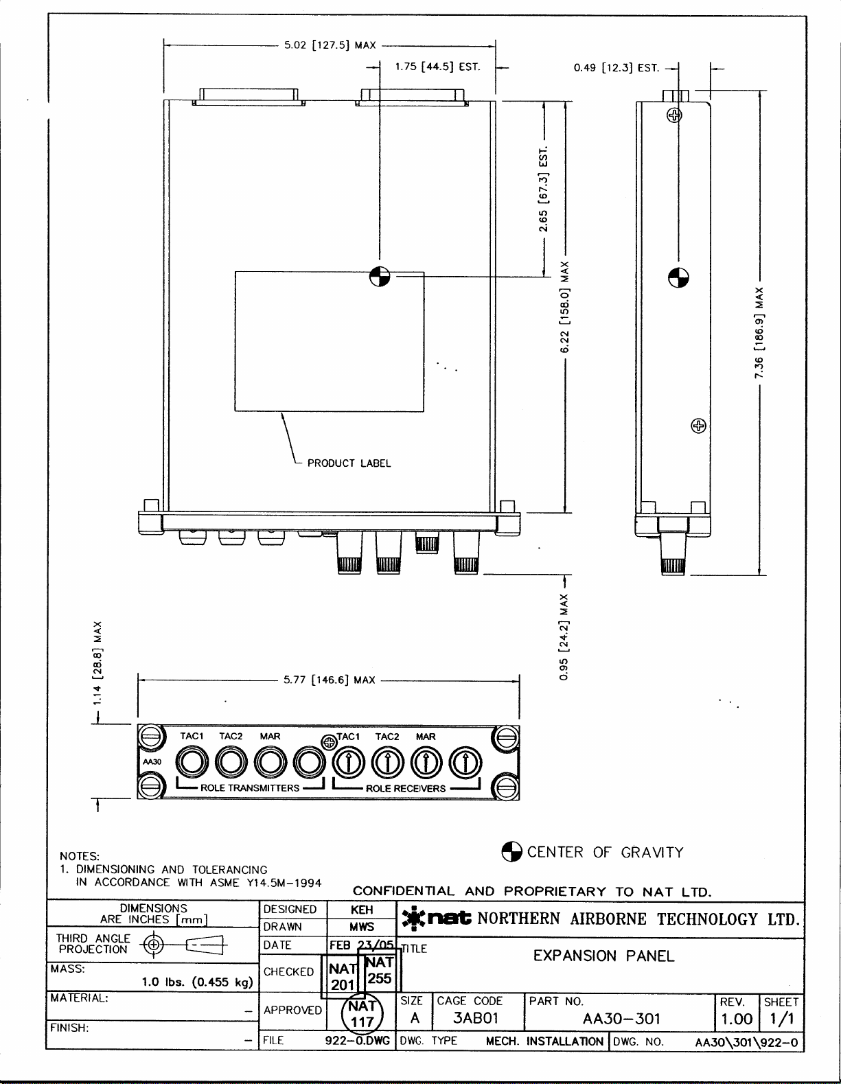
1.4.2 Physical Specifications
Height 1.14" (28.8 mm) max
Depth behind panel 6.22" (158.0 mm) max excluding connectors
Width 5.02" (127.5 mm) max behind panel
Weight 1.15 lb (0.52 kg) max
Mounting Dzus rail, 4 fasteners 5.366" horizontal spacing,
0.750" vertical spacing
Faceplate Laser-engraved edge-lit panel with blue/white
lighting
Material/Finish Chassis and cover are 5052-H32 brushed
aluminum with chromate conversion finish.
Connectors: J101 Receive I/O and Power Connections
One male 25-pin D-subminiature connector
with jackpost hardware
J102 Mic and Key I/O Connections:
One female 25-pin D-subminiature connector
with jackpost hardware
Installation kit: AA12-IKC (D25P25SL-IKC)
1.4.3 Environmental Specifications
Temperature -55 °C to +70 °C
Altitude +55,000 ft.
Humidity >95%, 48 hours
Shock 6g for 11 ms in all axes
Qualification:
Oct 16, 2006 Page 1-3
ENG-FORM: 800-0108.DOT
CONFIDENTIAL AND PROPRIETARY TO NORTHERN AIRBORNE TECHNOLOGY LTD.
Page 10

AA30-301 Expansion Panel Manual SM74 Rev. 4.10
Up to serial number 3000:
Internal Model 247 amplifier subassembly meets the requirements of TSO-C50c and
RTCA/DO-160C
Env. Cat: [A2F2]-BA[CL]XXXXXXZ[BZ]AAATZ[XXC2]XX.
Serial number 3001 and higher:
RTCA/DO-160E Env. Cat. [(A2)(F2)-]BAB[(RBB1)(SM)]XXXXXXZZAZ[AC][TT]M[XXC1X]XXXX
Note: Refer to the Environmental Qualification Form in Section 2.6 of this manual for
complete details of the environmental categories.
1.4.4 Certification
Applicable to serial number 3001 and above:
FAA TSO-C139 Aircraft Audio Systems and Equipment
RTCA DO-214 Class Ib Audio Systems characteristics and minimum operational
performance standards for audio systems and equipment.
End of section 1
Page 1-4 Oct 16, 2006
ENG-FORM: 800-0108.DOT
CONFIDENTIAL AND PROPRIETARY TO NORTHERN AIRBORNE TECHNOLOGY LTD.
Page 11

SM74 Rev. 4.10 AA30-301 Expansion Panel Manual
Section 2 Installation
2.1 Introduction
Information in this section consists of: unpacking and inspection procedures, installation
procedures, post-installation checks, and installation drawings.
2.2 Unpacking and Inspection
Unpack the equipment carefully and locate the warranty card. Inspect the unit visually
for damage due to shipping and report all such claims immediately to the carrier
involved. Note that each unit should have the following:
- AA30-301 Expansion Panel
- Warranty Card
- Operator’s Manual
- Release certification
Verify that all items are present before proceeding and report any shortage immediately
to your supplier.
2.2.1 Warranty
Complete the warranty card information and send it to NAT when the installation is
complete. If you fail to complete the warranty card, the warranty will be activated on
date of shipment from NAT.
Note: An appropriately rated facility, e.g. Certified Aircraft Repair Station, must install
this equipment in accordance with applicable regulations. NAT Ltd’s warranty is
not valid unless the equipment is installed by an authorized NAT Dealer. Failure
to follow any of the installation instructions, or installation by a non-certified
individual or agency will void the warranty, and may result in a non-airworthy
installation.
2.3 Installation Procedures
2.3.1 Warnings
Do not bundle any lines from this unit with transmitter coax lines. Do not bundle any
audio or DC power lines from this unit with 400 Hz synchro wiring or AC power lines. Do
not position this unit or wiring from this unit next to any device with a strong alternating
magnetic field such as an inverter, or significant audio interference will result.
Oct 16, 2006 Page 2-1
ENG-FORM: 805-0107.DOT
CONFIDENTIAL AND PROPRIETARY TO NORTHERN AIRBORNE TECHNOLOGY LTD.
Page 12

AA30-301 Expansion Panel Manual SM74 Rev. 4.10
2.3.2 Cautions
In all installations, use shielded cable exactly as shown and ground as indicated.
Significant ground loop and noise problems may result from not following these
guidelines.
The shielding and routing of the receive audio lines used in the AA30-301 installation is
very critical and poor performance of the aircraft audio system will result if the
installation shown on Interconnect drawing AA30\301\403-0 and -1 is not followed.
2.3.3 Cabling and Wiring
All unshielded wire shall be selected in accordance with AC43.13-1B Change 1,
Paragraphs 11-76 through 11-78. Wire types should be to MIL-W-22759 as specified in
AC43.13-1B Change 1, Paragraphs 11-85, 11-86, and listed in Table 11-11. For
shielded wire applications, use Tefzel MIL-C-27500 shielded wire with solder sleeves
(for shield terminations) to make the most compact and easily terminated interconnect.
Follow the wiring diagrams in Section 2.6 as required.
Allow 3 inches from the end of the wire to the shield termination to allow the hood to be
easily installed. Note that the hood is a ‘clamshell’ hood, and is installed after the wiring
is complete.
All wiring should be at least 22 AWG, except power and ground lines, which should be
at least 20 AWG. Ensure that all ground connections are clean and well secured.
2.3.4 Post-Installation Checks
2.3.4.1 Voltage/Resistance Checks
Check the following:
a) P101 pin <13> for +28 Vdc avionics buss voltage.
b) P101 pin <12> for +28 Vdc lighting buss voltage.
c) P101 pins <15> <16> <18> <20> <22> and <25> for continuity to ground (power).
d) P101 pin <24> for continuity to ground (lighting).
2.3.4.2 Power On Checks
WARNING:
High volume settings can cause hearing damage.
Set the headset volume control to the minimum volume
setting prior to conducting audio tests, and slowly increase
the headset volume level to a comfortable listening level.
Page 2-2 Oct 16, 2006
ENG-FORM: 805-0107.DOT
CONFIDENTIAL AND PROPRIETARY TO NORTHERN AIRBORNE TECHNOLOGY LTD.
Page 13

SM74 Rev. 4.10 AA30-301 Expansion Panel Manual
a) Install the AA30-301 and power up the aircraft’s systems. Turn on the radios and
accessories required for the system.
b) Check for correct radio audio and adjust for acceptable level.
c) Run through all installed functions, and check the RX and TX functions for all
users. Refer to Section 3 for specific operation details.
d) If any preset requires adjustment, be sure this is carried out before the aircraft
leaves, and that the unit and its mating connector are secured before departure.
Make all required log book entries, electrical load, weight and balance
amendments and other paperwork as required by your local regulatory agency.
2.3.5 Adjustments
The unit is shipped from the factory with all internal adjustments set to the normal test
levels. Once installed in the aircraft, it may be desirable to change some of these settings
to best suit the local operating environment.
INPUT 2
INPUT 1
INPUT 4
INPUT 3
The gain of the COM RX inputs can be adjusted using
potentiometers, accessible through holes in the top cover of the
unit. Each hole is labelled to identify inputs 1 through 4 (see
table).
COM RX Inputs Label Potentiometer
COM 1 INPUT 1 VR2
COM 2 INPUT 2 VR1
COM 3 INPUT 3 VR4
COM 4 INPUT 4 VR3
Upon satisfactory completion of all performance checks, make the required log
entries and complete the necessary Regulatory Agency paperwork before
releasing the aircraft for service.
2.4 Continued Airworthiness
Maintenance of the AA30-301 is ‘on condition’ only. Periodic maintenance of this
product is not required.
Oct 16, 2006 Page 2-3
ENG-FORM: 805-0107.DOT
CONFIDENTIAL AND PROPRIETARY TO NORTHERN AIRBORNE TECHNOLOGY LTD.
Page 14

AA30-301 Expansion Panel Manual SM74 Rev. 4.10
2.5 Accessories Required But Not Supplied
Installation kit D25P25SL-IKC (Alt Part No AA12-IKC) is required to complete the
installation. The kit consists of the following:
One D25SL-IKC 25 Pin D-min Female Crimp Kit
Quantity Description NAT Part #
1 D-min 25 Socket Housing 20-21-025
25 MS Crimp Socket 20-26-901
1* Jack Screw Set 20-27-002
1* Lock Clip Set 20-27-004
1 25 Pin Connector Hood 20-29-026
One D25PL-IKC 25 Pin D-min Male Crimp Kit
Quantity Description NAT Part #
1 D-min 25 Pin Housing 20-11-025
25 MS Crimp Pin 20-26-891
1* Jack Screw Set 20-27-002
1* Lock Clip Set 20-27-004
1 25 Pin Connector Hood 20-29-026
* Use as required.
2.6 Installation Drawings
DRAWING REV. DESCRIPTION TYPE SERIAL #
AA30\301\403-0 1.11 Expansion Panel Interconnect All
AA30\301\403-1 1.11 Expansion Panel Interconnect All
AA30\301\405-0 1.00 Expansion Panel Connector Map All
AA30\301\521-0 1.00 Expansion Panel Environmental Qual Form 3001 and up
AA30\301\905-0 1.00 Expansion Panel Faceplate All
AA30\301\922-0 1.00 Expansion Panel Mech. Installation 1224-1260
AA30\301\922-0 1.10 Expansion Panel Mech. Installation 1261 - 1268
AA30\301\922-0 1.20 Expansion Panel Mech. Installation 1269 - 1282
AA30\301\922-0 1.30 Expansion Panel Mech. Installation 1283 - 3000
AA30\301\922-0 1.31 Expansion Panel Mech. Installation 3001 and up
Section 2 ends after these Drawings
Page 2-4 Oct 16, 2006
ENG-FORM: 805-0107.DOT
CONFIDENTIAL AND PROPRIETARY TO NORTHERN AIRBORNE TECHNOLOGY LTD.
Page 15

Page 16

Page 17

Page 18

Page 19

Page 20

Page 21

Page 22

AA30-3xx Environmental Qualification Form
Conditions Section Description of Conducted Tests
Vibration
Explosion
Waterproofness
Fluids Susceptibility
Sand and Dust
Fungus
Salt Spray
Magnetic Effect
Power Input
Voltage Spike
Audio Frequency Susceptibility
Induced Signal Susceptibility
8.0
9.0
10.0
11.0
12.0
13.0
14.0
15.0
16.0
17.0
18.0
19.0
Equipment tested to Category [(RBB1)(SM)]
(without shock mounts).
• The equipment was also tested to vibration
profile F (one hour per axis) per DO-160E
sub-paragraph 8.3.3 a) and met the minimum
performance standard.
Equipment identified as Category X no test
required.
Equipment identified as Category X no test
required.
Equipment identified as Category X no test
required.
Equipment identified as Category X no test
required.
Equipment identified as Category X no test
required.
Equipment identified as Category X no test
required.
Equipment is Class Z.
Equipment tested to Category Z.
• Equipment was tested to subparagraph
16.6.1.3 b, requirement for digital circuits.
• Emergency Operating Voltage was tested.
Equipment tested to Category A
Equipment tested to Category Z
Equipment tested to Category [AC]
Rev: 1.00 Oct 20, 2006 Page 2 of 3
ENG-FORM: 521-0102.DOT
CONFIDENTIAL AND PROPRIETARY TO NORTHERN AIRBORNE TECHNOLOGY LTD.
Page 23

AA30-3xx Environmental Qualification Form
Conditions Section Description of Conducted Tests
Radio Frequency Susceptibility
20.0
Equipment tested to Category [TT]
• Sub-paragraph 20.5 Radiated Susceptibility
was tested per DO-214 section 2.5.11 and
DO-160E
Radio Frequency Emission
Lightning Induced Transient
Susceptibility
21.0
22.0
Equipment tested to Category M
Equipment tested to Category [XXC1X]
Lightning Direct Effects test
23.0
Equipment identified as Category X no test
required
Icing
24.0
Equipment identified as Category X no test
required
ESD
25.0
Equipment identified as Category X no test
required
Fire, Flammability
26.0
Equipment identified as Category X no test
required.
Other Test
Fire resistance tests on the faceplate material
were conducted in accordance with Federal
Aviation Regulations Part 25, Appendix F
REMARKS
- DO-160E, Sections 4 to 8, and 15 to 22 tests were conducted at Northern Airborne
Technology Ltd. (NAT) in Kelowna, BC on model AA30-301.
- Fire resistance tests were performed at Bodycote Materials Testing Canada Inc in
Mississauga, ON on a sample of faceplate material.
End of Environmental Qualification Form
Rev: 1.00 Oct 20, 2006 Page 3 of 3
ENG-FORM: 521-0102.DOT
CONFIDENTIAL AND PROPRIETARY TO NORTHERN AIRBORNE TECHNOLOGY LTD.
Page 24

Page 25

Page 26

Page 27
Page 28

Page 29

TAC1 TAC2 MAR TAC1 TAC2 MAR
AA30
ROLE TRANSMITTERS ROLE RECEIVERS
Page 30

Page 31

TAC1 TAC2 MAR TAC1 TAC2 MAR
AA30
ROLE TRANSMITTERS ROLE RECEIVERS
Page 32

Page 33

TAC1 TAC2 MAR TAC1 TAC2 MAR
AA30
ROLE TRANSMITTERS ROLE RECEIVERS
Page 34

Page 35

TAC1 TAC2 MAR TAC1 TAC2 MAR
AA30
ROLE TRANSMITTERS ROLE RECEIVERS
Page 36

Page 37

SM74 Rev. 4.10 AA30-301 Expansion Panel Manual
r
Section 3 Operation
3.1 Introduction
Information in this section consists of the functional and operational procedures for the
AA30-301 Expansion Panel.
3.2 General
The AA30-301 Expansion Panel is a Dzus-mounted 4-transceiver or radio receiver
expansion panel, designed to work in conjunction with the 380-series Audio Selector
Panels.
3.3 Controls and Indicators
The AA30-301 provides four ganged transmitter selector pushbutton switches and four
receiver level panel potentiometers, each with an integral push-in / push-out selector switch.
The laser-engraved text of the faceplate and any selected transmitter or receiver control
is illuminated when backlighting power is supplied to the unit.
3.3.1 Transmitter Selection
The transmitter control switches are four push
switches that are used to select transceivers fo
transmission.
When the transmitter control switch is the extended (out) position, the corresponding
transmitter is deselected (off), and the integral mechanical annunciator appears black
behind the clear window, and when the transmitter control switch is in the depressed
(in) position, the corresponding transmitter is selected (on), and the integral mechanical
annunciator appears green behind the clear window.
The default position for all transmitters is deselected (out).
The transmitter controls are designed to prevent accidental selection of more than one
transmitter; pushing a transmitter control switch locks it into the depressed (in) position and
cancels any previously selected transmitter control by returning it to the extended position.
Oct 16, 2006 Page 3-1
ENG-FORM: 806-0106.DOT
CONFIDENTIAL AND PROPRIETARY TO NORTHERN AIRBORNE TECHNOLOGY LTD.
Page 38

AA30-301 Expansion Panel Manual SM74 Rev. 4.10
r
j
All transmitters may be deselected by partially depressing any unselected transmitter
control.
When a transmitter is selected, the mic key and mic audio signals are automatically
directed to that transmitter.
A selected transmitter control bypasses the corresponding receiver control selector
switch (see section 3.3.2) to provide an auto-receive function.
3.3.2 Receiver Selection
The receiver control switches are fou
push-on/push-off rotary switches that are used to
select receivers and ad
ust volumes.
3.3.2.1 Selection
When the receiver control switch is in the default depressed (in) position, the
corresponding receiver is deselected (off), and when the receiver control switch is in the
extended (out) position, the corresponding receiver is selected (on).
The default position for all receivers is deselected (in).
The auto-receive function automatically selects a receiver for audio when the
corresponding transmitter control is depressed, even if the receiver control is not in the
selected position.
Receiver controls are independent; any combination of receivers may be simultaneously
selected.
3.3.2.2 Volume Control
The volume for each receiver can be adjusted by rotating the corresponding control.
The receiver volume is decreased to minimum at the full counterclockwise (ccw) stop,
and increased to maximum at the full clockwise (cw) stop.
If a receiver is activated by the Auto-receive function, the level is set by the current
receiver volume control, even if the control is deselected.
End of section 3
Page 3-2 Oct 16, 2006
ENG-FORM: 806-0106.DOT
CONFIDENTIAL AND PROPRIETARY TO NORTHERN AIRBORNE TECHNOLOGY LTD.
 Loading...