

Page 1
SM73
AA30-0xx
Expansion Switches
INSTALLATION AND OPERATION MANUAL
REV 4.00 September 18, 2006
Northern Airborne Technology Ltd.
1925 Kirschner Road
Kelowna, BC, Canada.
V1Y 4N7
Telephone (250) 763-2232
Facsimile (250) 762-3374
Copyright 2006 by Northern Airborne Technology
CONFIDENTIAL AND PROPRIETARY TO NORTHERN AIRBORNE TECHNOLOGY LTD.
Page 2

Page 3
SM73 Rev. 4.00 AA30-0xx Expansion Switches Manual
Periodically NAT will release manual amendments. In order to maintain the most
accurate and up to date manual these amendments should be carried out immediately
upon receipt and recorded on the following amendment record.
AMENDMENT RECORD
Amendment
Number
Note: Revision 4.00 is the first public release of this document
Amendment
Date
Section(s)
Changed
Date
Entered
Entered By
Insert any Amendment Instruction sheets after this page.
Sep 18, 2006 Page ii
ENG-FORM: 820-0110.DOT
CONFIDENTIAL AND PROPRIETARY TO NORTHERN AIRBORNE TECHNOLOGY LTD.
Page 4

Page 5

SM73 Rev. 4.00 AA30-0xx Expansion Switches Manual
Table of Contents
Section Title Page
1 Description
1.1 Introduction 1-1
1.2 Purpose of Equipment 1-1
1.3 Features 1-1
1.4 Specifications 1-1
1.4.1 Electrical Specifications 1-1
1.4.2 Physical Specifications 1-2
2 Installation
2.1 Introduction 2-1
2.2 Unpacking and Inspection 2-1
2.2.1 Warranty 2-1
2.3 Installation Procedures 2-1
2.3.1 Warnings 2-1
2.3.2 Cautions 2-2
2.3.3 Cabling and Wiring 2-2
2.3.4 Post-Installation Checks 2-2
2.3.5 Adjustments 2-3
2.4 Continued Airworthiness 2-3
2.5 Accessories Required But Not Supplied 2-3
2.6 Installation Drawings 2-4
3 Operation
3.1 Introduction 3-1
3.2 General 3-1
3.3 Controls and Indicators 3-1
3.3.1 Transmit Selector 3-1
3.3.2 Receive Audio Switches 3-1
Sep 18, 2006 Page iii
ENG-FORM: 820-0110.DOT
CONFIDENTIAL AND PROPRIETARY TO NORTHERN AIRBORNE TECHNOLOGY LTD.
Page 6

Page 7

SM73 Rev. 4.00 AA30-0xx Expansion Switches Manual
Section 1 Description
1.1 Introduction
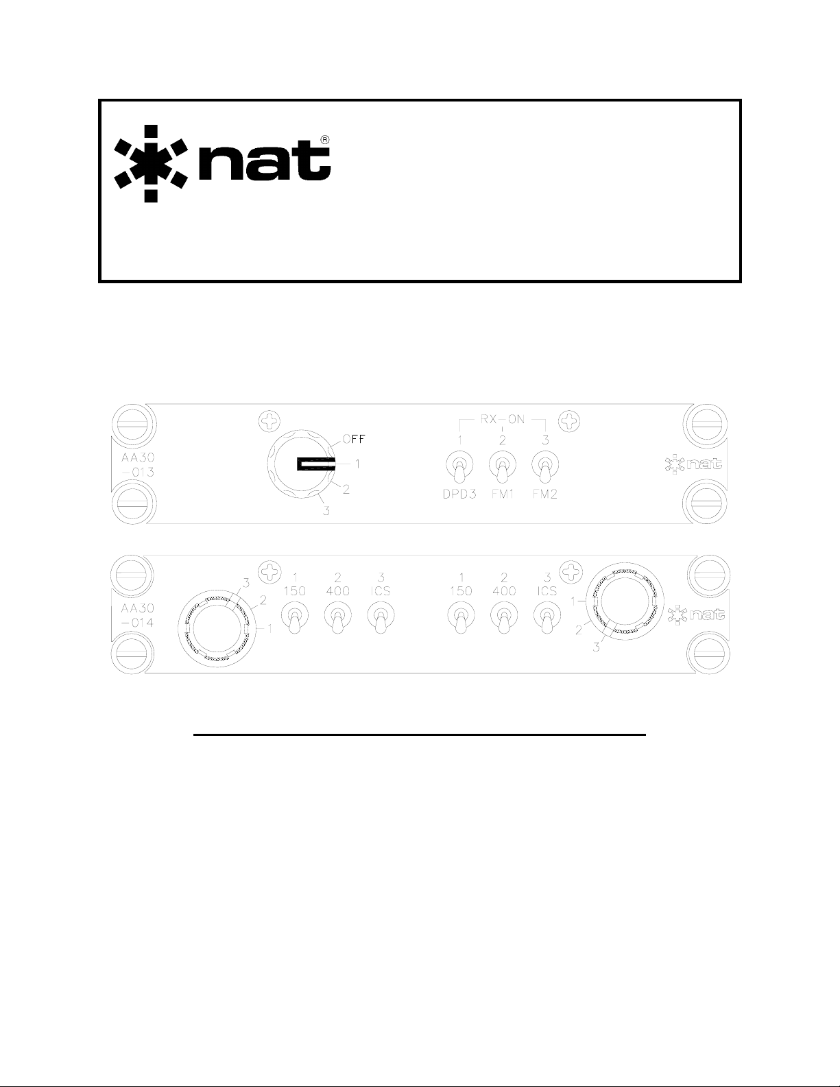
This manual contains general information on the AA30-0xx Expansion Switches. There
are many different variants of the AA30-0xx available; in this manual the AA30-013 is
described as an example of a single user unit, and the AA30-014 as an example of a
dual user unit. All derivative products will be covered by manual supplements, which
can be obtained from NAT as required.
Information in this section consists of purpose of equipment, features and specifications.
1.2 Purpose of Equipment
The AA30-013 is a single-position expansion switch, and the AA30-014 is a dualposition expansion switch. Both provide transmit capability.
1.3 Features
The AA30-013 is a compact Dzus mounted switch expansion unit that provides
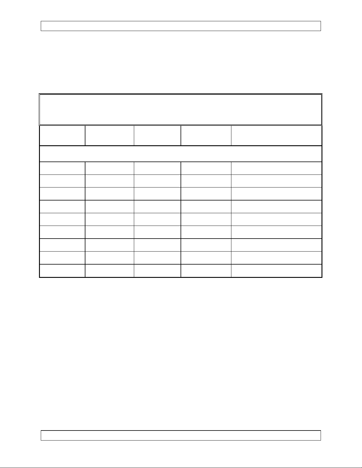
expansion for one user and contains only one board. The AA30-014 is a compact Dzus
mounted switch expansion unit that provides independent expansion for two users,
using two identical circuit boards.
The transmit function allows each user to select one of three transceivers (or two
transceivers and intercom). Receive audio can be selected regardless of the transmit
selector switch position.
1.4 Specifications
1.4.1 Electrical Specifications
Power Supply No internal power supply
Input Signals
+28 Vdc Power (AA30-014 only)
Operating Voltage Nominal 27.5 Vdc
Minimum 17.0 Vdc
Maximum 35.5 Vdc
Input Current 50 mA Max @ 27.5 Vdc
Backlight Power (may be connected to one or both connectors on AA30-014)
Sep 18, 2006 Page 1-1
ENG-FORM: 800-0108.DOT
CONFIDENTIAL AND PROPRIETARY TO NORTHERN AIRBORNE TECHNOLOGY LTD.
Page 8

AA30-0xx Expansion Switches Manual SM73 Rev. 4.00
Voltage 28 Vdc
Return Lights Ground
Mic: Quantity 1 per user
Circuitry Type Single Ended
Keyline: Quantity 1 per user
Active State Low (A/C ground)
RX Audio: Quantity 3 per user
Circuitry Type Single Ended
Output Signals
Mic: Quantity 3 per user
Circuitry Type Single Ended
Keyline: Quantity 3 per user
Active State Low (A/C ground)
Phones: Quantity 1 per user
Circuitry Type Single Ended
1.4.2 Physical Specifications
Height 1.14" (29.0 mm) max
Depth behind panel 5.82" (147.8 mm) max (including connectors)
Width behind panel 4.92" (125.0 mm) max wide
Weight AA30-013 0.70 lbs (0.32 kg) max
AA30-014 0.95 lbs (0.43 kg) max
Mounting Dzus rail
Faceplate Acrylic edge-lit panel
Material/Finish Chassis and cover are 5052-H32 brushed
aluminum with chromate conversion finish.
Connectors One (AA30-013) or two (AA30-014) male 25-pin
D-subminiature connectors with jackposts.
End of section 1
Page 1-2 Sep 18, 2006
ENG-FORM: 800-0108.DOT
CONFIDENTIAL AND PROPRIETARY TO NORTHERN AIRBORNE TECHNOLOGY LTD.
Page 9

SM73 Rev. 4.00 AA30-0xx Expansion Switches Manual
Section 2 Installation
2.1 Introduction
Information in this section consists of: unpacking and inspection procedures, installation
procedures, post-installation checks, and installation drawings.
2.2 Unpacking and Inspection
Unpack the equipment carefully and locate the warranty card. Inspect the unit visually
for damage due to shipping and report all such claims immediately to the carrier
involved. Note that each unit should have the following:
- AA30-0xx Expansion Switch
- Warranty Card
- Operator’s Manual
- Release certification
Verify that all items are present before proceeding and report any shortage immediately
to your supplier.
2.2.1 Warranty
Complete the warranty card information and send it to NAT when the installation is
complete. If you fail to complete the warranty card, the warranty will be activated on
date of shipment from NAT.
Note: An appropriately rated facility, e.g. Certified Aircraft Repair Station, must install
this equipment in accordance with applicable regulations. NAT Ltd’s warranty is
not valid unless the equipment is installed by an authorized NAT Dealer. Failure
to follow any of the installation instructions, or installation by a non-certified
individual or agency will void the warranty, and may result in a non-airworthy
installation.
2.3 Installation Procedures
2.3.1 Warnings
Do not bundle any lines from this unit with transmitter coax lines. Do not bundle any
audio or DC power lines from this unit with 400 Hz synchro wiring or AC power lines. Do
not position this unit or wiring from this unit next to any device with a strong alternating
magnetic field such as an inverter, or significant audio interference will result.
Sep 18, 2006 Page 2-1
ENG-FORM: 805-0107.DOT
CONFIDENTIAL AND PROPRIETARY TO NORTHERN AIRBORNE TECHNOLOGY LTD.
Page 10

AA30-0xx Expansion Switches Manual SM73 Rev. 4.00
2.3.2 Cautions
In all installations, use shielded cable exactly as shown and ground as indicated.
Significant ground loop and noise problems may result from not following these
guidelines.
The shielding and routing of the MIC LINES used in the AA30-0xx installation is very
critical and poor performance of the aircraft audio system will result if these issues are
not handled properly.
2.3.3 Cabling and Wiring
All unshielded wire shall be selected in accordance with AC43.13-1B Change 1,
Paragraphs 11-76 through 11-78. Wire types should be to MIL-W-22759 as specified in
AC43.13-1B Change 1, Paragraphs 11-85, 11-86, and listed in Table 11-11. For
shielded wire applications, use Tefzel MIL-C-27500 shielded wire with solder sleeves
(for shield terminations) to make the most compact and easily terminated interconnect.
Follow the wiring diagrams in Section 2.6 as required.
Allow 3 inches from the end of the wire to the shield termination to allow the hood to be
easily installed. Note that the hood is a ‘clamshell’ hood, and is installed after the wiring
is complete.
All wiring should be at least 22 AWG, except power and ground lines, which should be
at least 20 AWG. Ensure that all ground connections are clean and well secured.
2.3.4 Post-Installation Checks
2.3.4.1 AA30-013 Voltage/Resistance Checks
Check the following:
a) P101 pin <9> for +28 Vdc lighting buss voltage.
b) P101 pin <22> and <24> for continuity to ground.
2.3.4.2 AA30-014 Voltage/Resistance Checks
Check the following:
a) P101 and P102 pins <7> for +28 Vdc avionics buss voltage.
b) P101 and P102 pins <9> for +28 Vdc lighting buss voltage (only one required).
c) P101 and P102 pins <22> and <24> for continuity to ground.
d) P101 and P102 pins <11> for continuity to ground when keyed.
Page 2-2 Sep 18, 2006
ENG-FORM: 805-0107.DOT
CONFIDENTIAL AND PROPRIETARY TO NORTHERN AIRBORNE TECHNOLOGY LTD.
Page 11

SM73 Rev. 4.00 AA30-0xx Expansion Switches Manual
2.3.4.3 Power On Checks
WARNING:
High volume settings can cause hearing damage.
Set the headset volume control to the minimum volume
setting prior to conducting these tests and slowly increase
the headset volume level to a comfortable listening level.
a) Install the AA30-0xx and power up the ship’s systems. Turn on the radios and
accessories required for the system.
b) Check for correct radio audio and adjust for acceptable level.
c) Run through all installed functions, and check the RX and TX functions for all
users. Refer to Section 3 for operation details.
2.3.5 Adjustments
The unit is shipped from the factory with all internal adjustments set to the normal test
levels. Once installed in the aircraft, it may be desirable to change some of these settings
to best suit the local operating environment.
2.3.5.1 Sidetone Level (AA30-014 only)
The sidetone level pots can be accessed through holes in the side of the unit.
When the pot is rotated fully counterclockwise the sidetone level will be at its minimum.
Rotating the pot clockwise will increase the level.
Upon satisfactory completion of all performance checks, make the required log
entries and complete the necessary Regulatory Agency paperwork before
releasing the aircraft for service.
2.4 Continued Airworthiness
Maintenance of the AA30-0xx is ‘on condition’ only. Periodic maintenance of this
product is not required.
2.5 Accessories Required But Not Supplied
Installation kits are required to complete the installation. Different kits are required
depending upon the model - for information, please contact the Product Support
Department at NAT Ltd.
Sep 18, 2006 Page 2-3
ENG-FORM: 805-0107.DOT
CONFIDENTIAL AND PROPRIETARY TO NORTHERN AIRBORNE TECHNOLOGY LTD.
Page 12

AA30-0xx Expansion Switches Manual SM73 Rev. 4.00
2.6 Installation Drawings
The AA30-013 is described as an example of a single user unit, and the AA30-014 as
an example of a dual user unit.
DRAWING REV. DESCRIPTION TYPE
AA30-013
AA30\013\403-0 1.10 Expansion Switch Unit Interconnect
AA30\013\405-0 1.10 Expansion Switch Unit Connector Map
AA30\013\905-0 1.00 Expansion Switch Unit Faceplate
AA30\013\922-0 1.00 Expansion Switch Unit Mech. Installation
AA30-014
AA30\014\403-0 1.00 Expansion Switch Unit with TX Interconnect
AA30\014\405-0 1.00 Expansion Switch Unit with TX Connector Map
AA30\014\905-0 1.00 Expansion Switch Unit with TX Faceplate
AA30\014\922-0 1.10 Expansion Switch Unit with TX Mech. Installation
Section 2 ends after these Drawings
Page 2-4 Sep 18, 2006
ENG-FORM: 805-0107.DOT
CONFIDENTIAL AND PROPRIETARY TO NORTHERN AIRBORNE TECHNOLOGY LTD.
Page 13

Page 14

Page 15

Page 16

Page 17

Page 18

Page 19

AA30
-013
OFF
1
2
3
RX-ON
31 2
FM2DPD3 FM1
Page 20

Page 21

Page 22

Page 23

Page 24

Page 25

Page 26

Page 27

AA30
-014
1 2 3 21 3
3
150
2
400 ICS 400150 ICS
1
S/T
1
2
3
Page 28

Page 29

SM73 Rev. 4.00 AA30-0xx Expansion Switches Manual
Section 3 Operation
3.1 Introduction
Information in this section consists of the functional and operational procedures for the
AA30-0xx Expansion Panels.
The AA30-013 is described as an example of a single user unit, and the AA30-014 as
an example of a dual user unit.
3.2 General
The AA30-0xx Series are Dzus-mounted expansion panels designed to expand a single
transceiver selection from an audio control panel to allow three transceiver selections.
These units are generally part of a larger system with other audio controllers or
equipment; the whole system must be considered, not just the AA30-0xx accessory unit.
3.3 Controls and Indicators
The controls on both the dual and single user versions of the AA30 work in a similar
manner; for simplicity, only one set of controls will be described.
Transmit Selectors
Receive Audio Switches
3.3.1 Transmit Selector
The transmit selector is a rotary plastic switch used to select the transceiver output for
transmission.
3.3.2 Receive Audio Switches
The three receive audio selection switches are two-position on-off switches. They select
the required receive audio when in the 'up' (on) position.
End of section 3
Sep 18, 2006 Page 3-1
ENG-FORM: 806-0106.DOT
CONFIDENTIAL AND PROPRIETARY TO NORTHERN AIRBORNE TECHNOLOGY LTD.
Page 30

 Loading...