

Page 1
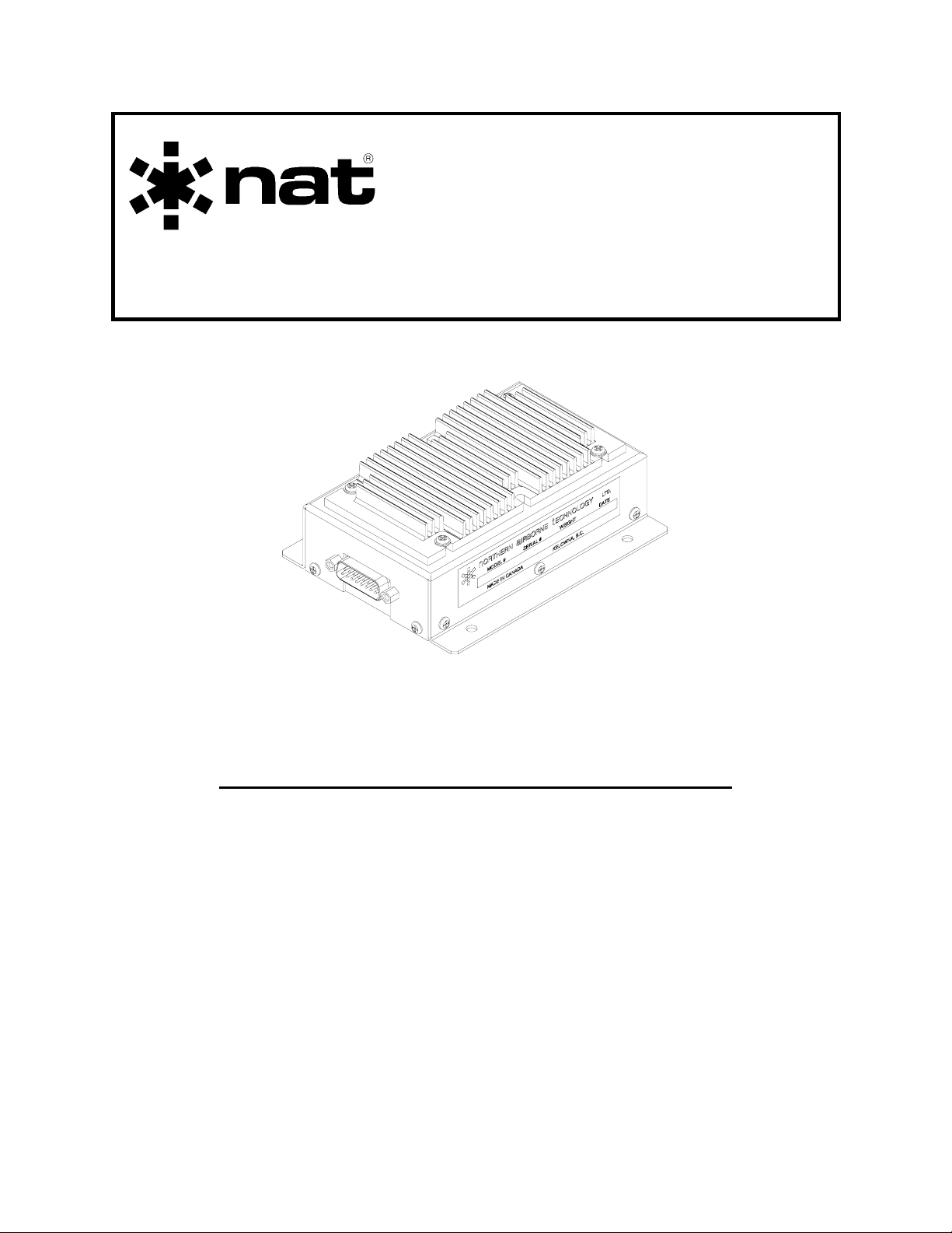
SM23
AA23
Speaker Amplifier
INSTALLATION AND OPERATION MANUAL
REV 4.00 November 21, 2003
Northern Airborne Technology Ltd.
1925 Kirschner Road
Kelowna BC, Canada
V1Y 4N7
Telephone (250) 763-2232
Facsimile (250) 762-3374
Copyright 2003 by Northern Airborne Technology
CONFIDENTIAL AND PROPRIETARY TO NORTHERN AIRBORNE TECHNOLOGY LTD.
Page 2

Page 3
SM23 Rev. 4.00 AA23 Speaker Amplifier Manual
Performed at factory
Periodically NAT will release manual amendments. In order to maintain the most
accurate and up to date manual these amendments should be carried out immediately
upon receipt and recorded on the following amendment record.
AMENDMENT RECORD
Amendment
Number
Amendment
Date
Section(s)
Changed
Date
Entered
Entered By
809-0001 Oct 29,2004 2 Oct 29,2004
Nov 21, 2003 Page ii
ENG-FORM: 820-0109.DOT
CONFIDENTIAL AND PROPRIETARY TO NORTHERN AIRBORNE TECHNOLOGY LTD.
Insert any Amendment Instruction sheets after this page.
Page 4

Page 5
INSTALL_OPS MANUAL
AMENDMENT
Manual: SM23 (AA23) Amendment #: 1
Document # SM23\Install_Ops\809-0001 Amendment Date: Oct 29, 2004
The purpose of this amendment is to add the most recent drawings to the installation
section of the manual.
Amendment Instructions:
1 Remove Pages Replace With Pages
2-3 Rev. 4.00 2-3 Rev. 4.00 Amendment #1
2 Remove Drawings (Section 2) Replace or add Drawings (Section 2)
- AA23\922-0 Rev. 1.30
Note: Ensure that all drawings are inserted in the order shown on the latest drawing lists.
3 Update the Amendment Record sheet at the front of the manual.
4 Insert this page into the manual after the Amendment Record sheet (page ii).
Manual Amendment ends after the following amended pages
Amendment # 1 Oct 29, 2004 Page 1
ENG-FORM: 809-0108.DOT
PROPRIETARY AND CONFIDENTIAL TO NORTHERN AIRBORNE TECHNOLOGY LTD.
Page 6

Page 7

SM23 Rev. 4.00 AA23 Speaker Amplifier Manual
Table of Contents
Section Title Page
1.0 Description
1.1 Introduction 1-1
1.2 Purpose of Equipment 1-1
1.3 Features 1-1
1.4 Specifications 1-2
1.4.1 Electrical Specifications 1-2
1.4.2 Physical Specifications 1-3
1.4.3 Environmental Specifications 1-3
1.5 Accessories Required but not supplied 1-3
1.6 Unit Nomenclature 1-4
2.0 Installation
2.1 Introduction 2-1
2.2 Unpacking and Inspection 2-1
2.3 Installation Procedures 2-1
2.3.1 Warnings 2-1
2.3.2 Cautions 2-1
2.3.3 Notes 2-2
2.3.4 Cable and Wiring 2-2
2.3.5 External Components 2-2
2.3.6 Post-Installation Checks 2-2
2.4 Continued Airworthiness 2-3
2.5 Installation Drawings 2-3
3.0 Operation
3.1 Introduction 3-1
3.2 General 3-1
3.3 Performance 3-1
Nov 21, 2003 Page iii
ENG-FORM: 820-0109.DOT
CONFIDENTIAL AND PROPRIETARY TO NORTHERN AIRBORNE TECHNOLOGY LTD.
Page 8

Page 9

SM23 Rev. 4.00 AA23 Speaker Amplifier Manual
Section 1.0 Description
1.1 Introduction
This manual contains information on the AA23 Speaker Amplifier.
Information in this section consists of purpose of equipment, features and specifications.
1.2 Purpose of Equipment
The AA23 is a versatile speaker amplifier that can be used to convert balanced 600 Ω
line, 150/600 Ω headset, or carbon-equivalent microphone levels to speaker outputs.
The interface to the AA23 is fully floating (transformer coupled), permitting complex and
long distance interconnects and providing outstanding rejection of ground loop signals.
The speaker output is ground referenced.
The AA23 can be used for distributed music systems, paging, transfer of headset based
systems to speaker based outputs, or as a very high powered headset booster driver.
The output of the AA23 can be selected ON or OFF by a simple logic line (GND =
muted) to simplify external wiring in most applications.
Extensive key logic and muting capability is also incorporated into the AA23, which
addresses close cockpit installations, and provides some extra flexibility in difficult
installations. Either fully muted or partially muted installations can be accomplished
through interconnect pin selection.
The AA23 will drive any speaker load from 3.2 to 16 Ω, but provides optimum energy
transfer into either 4 or 8 Ω loads. If operated continuously with a high average power
level, the unit must have air exchange for the heat sink assembly to function properly.
1.3 Features
The AA23 incorporates a power (and fuse) monitor LED that allows in-place visual
indication of unit activity. The LED will turn off if either the external breaker or internal
fuse is tripped.
The AA23 incorporates an internal noise filter to eliminate DC coupled interference into
the system.
To provide a choice of bandpass operation (voice or music), the AA23 has an internal jumper
selection. With the jumper installed, the bandpass is slightly reduced to provide better voice
performance and improved feedback reduction. With the jumper removed, wide band music
operation can be achieved. The units are shipped with the jumper installed.
Nov 21, 2003 Page 1-1
ENG-FORM: 800-0106.DOT
CONFIDENTIAL AND PROPRIETARY TO NORTHERN AIRBORNE TECHNOLOGY LTD.
Page 10

AA23 Speaker Amplifier Manual SM23 Rev. 4.00
An internal trimpot is provided to permit level adjustment of the over-all system. As
shipped, range remains in both directions, up and down.
A set of uncommitted relay contacts (2 A rating) is provided that is closed when the unit
receives a mute command (key ground input). This can be used for external switching.
Fully muted (no output) and partially muted outputs are available to provide a choice of
enabled or disabled speaker sidetone. The muting circuit inserts a 44 Ω resistor in
series with the load, to reduce the output level.
Two external, unrelated key inputs can mute the AA23, and both provide a flow-through
key output to other systems. This permits two users in a close cockpit installation to
mute each other's speakers to prevent feedback, and provides outputs to the balance of
the audio system for TX keying.
The headset input places a greater than 1.8 kΩ load on the existing headset driver
system, which represents a negligible load. It is a fully floating input, and will not
introduce any ground loop interference unless grounded via the user interconnect. This
line is meant for signals of typically +17 dBm to +20 dBm (50 mW/600 Ω).
The 600 Ω line input can be used with lower level sources to provide a speaker buffer
as needed. Input sources can be music, radio feeds (via a pad) or other sources. Note
that this connection is the direct input to the AA23 transformer, and is isolated from the
headset input only by a simple resistive pad. Signals injected here may appear back at
the headset input, and cause problems if isolation was intended.
The mic input accepts a ‘carbon-equivalent’ unit, and has internal excitation from the
AA23. The input is floating, and must have a ground at the input low connection to
excite the microphone. This is normally provided by any NAT audio system if used to
provide the mic input (PA position).
1.4 Specifications
1.4.1 Electrical Specifications
Input Power +22 to 32 Vdc.
Supply Current 1.0 A max. (at full output into 3.2 Ω).
0.3 to 0.5 A (typical)
Input Levels
600 Ω input 0.45 Vrms (-5 dBm) at 1 kHz.
H/S Input 7.70 Vrms (+20 dBm) at 1 kHz.
Mic Input 0.25 Vrms at 1 kHz.
Page 1-2 Nov 21, 2003
ENG-FORM: 800-0106.DOT
CONFIDENTIAL AND PROPRIETARY TO NORTHERN AIRBORNE TECHNOLOGY LTD.
Page 11

SM23 Rev. 4.00 AA23 Speaker Amplifier Manual
Output Levels
3.2 Ω Load 9.0 Wrms @ 1 kHz with <0.6% distortion.
4.0 Ω Load 7.5 Wrms @ 1 kHz with <0.6% distortion.
8.0 Ω Load 4.5 Wrms @ 1 kHz with <0.5% distortion.
16 Ω Load 2.5 Wrms @ 1 kHz with <0.3% distortion.
Input Logic Key inputs are active LOW (GND = MUTED).
Output Logic Key outputs are diode isolated and track their
respective inputs less a 0.7 V diode drop.
1.4.2 Physical Specifications
Height 1.73 in (43.8 mm) including top heatsink.
Depth 5.20 in (132.1 mm) excluding connector. Allow
5 cm clearance for cable and connector.
Width 3.95 in (100.3 mm) including mounting flange.
Weight 0.78 lb (355 g) less mating connector.
Mounting 4 x 10-32 mounting bolt/screw.
Mounting Hole Centers 3.60 in (91.4 mm) by 3.45 in (87.6 mm).
1.4.3 Environmental Specifications
Temperature -20° C to + 65° C.
Altitude 15,000 ft. max.
Humidity 95 % Non-Condensing.
Shock 12 g. (any axis)
1.5 Accessories Required but not Supplied
Installation kit p/n AA23-IKC (crimp) or AA23-IKS (solder) is required to complete the
installation. They consist of the following:
AA23-IKC 15 Pin D-min Female Crimp Kit (NAT Part # D15SL-IKC)
Quantity Description NAT Part #
1 D-min 15 Socket Housing 20-21-015
15 MS Crimp Socket 20-26-901
1* Jack Screw Set 20-27-002
1* Lock Clip Set 20-27-004
1 15 Pin Connector Hood 20-29-015
* Use as required.
Nov 21, 2003 Page 1-3
ENG-FORM: 800-0106.DOT
CONFIDENTIAL AND PROPRIETARY TO NORTHERN AIRBORNE TECHNOLOGY LTD.
Page 12

AA23 Speaker Amplifier Manual SM23 Rev. 4.00
AA23-IKS 15 Pin D-min Female Solder Kit (NAT Part # D15SL-IKS)
Quantity Description NAT Part #
1 D-min 15 Socket Solder Cup 20-20-015
1* Jack Screw Set 20-27-002
1* Lock Clip Set 20-27-004
1 15 Pin Connector Hood 20-29-015
* Use as required.
1.6 Unit Nomenclature
Model Description / Distinction
AA23-001 Accepts Mic., 600 Ω Line and H/S inputs, with floating interface.
Muted or partially muted outputs.
Dual PTT key logic inputs and outputs.
Selectable frequency response, Voice or Music.
Adjustable gain.
AA23-002 Accepts Mic. and two H/S inputs, with floating interface.
Muted or partially muted outputs.
Dual PTT key logic inputs and outputs.
Selectable frequency response, Voice or Music.
Adjustable gain.
End of section 1.0
Page 1-4 Nov 21, 2003
ENG-FORM: 800-0106.DOT
CONFIDENTIAL AND PROPRIETARY TO NORTHERN AIRBORNE TECHNOLOGY LTD.
Page 13

SM23 Rev. 4.00 AA23 Speaker Amplifier Manual
Section 2.0 Installation
2.1 Introduction
Information in this section consists of: unpacking and inspection procedures, installation
procedures, post-installation checks, and installation drawings.
2.2 Unpacking and Inspection
Unpack the equipment carefully, and locate the warranty card. Inspect the unit visually
for damage due to shipping and report all such claims immediately to the carrier
involved. Note that each unit should have the following;
- AA23 Speaker Amplifier
- Warranty Card
- Release certification
Verify that all items are present before proceeding, and report any shortage immediately
to your supplier.
Complete the warranty card information, and send it to NAT when the installation is
complete. If you fail to complete the warranty card, the warranty will be activated on
date of shipment from NAT.
2.3 Installation Procedures
2.3.1 Warnings
Do not bundle any lines from this unit with transmitter coax lines, or AM audio
rectification may result. Do not bundle any input or output audio, or DC power lines
from this unit with 400 Hz synchro wiring or AC power lines. Do not position this unit or
wiring from this unit next to any device with a strong alternating magnetic field such as
an inverter, or significant audio interference will result.
2.3.2 Cautions
In all installations, use shielded cable exactly as shown and ground as indicated.
Significant problems may result from not following these guidelines, especially with
regard to ground loop noise.
Nov 21, 2003 Page 2-1
ENG-FORM: 805-0105.DOT
CONFIDENTIAL AND PROPRIETARY TO NORTHERN AIRBORNE TECHNOLOGY LTD.
Page 14

AA23 Speaker Amplifier Manual SM23 Rev. 4.00
2.3.3 Notes
The 600 Ω line input is a low level audio line, and connects to a sensitive point in the
AA23. This line must be shielded, and routed to avoid pick-up of stray fields in the
aircraft. The same holds true for the Headset and Mic inputs. Failure to do this will
result in noisy operation, and will easily pick up interference if poorly installed and
routed.
2.3.4 Cable and Wiring
All unshielded wire should be MIL-W-22759 or equivalent. For shielded wire
applications, use Tefzel MIL-C-27500 shielded wire with solder sleeves (for shield
terminations) to make the most compact and easily terminated interconnect. Follow the
wiring diagrams in Section 2.5 as required.
Allow 3 inches from the end of the wire to the shield termination to allow the hood to be
easily installed. Note that the hood is a “clamshell” hood, and is installed after the
wiring is complete.
All wiring should be 22 AWG, except power, output and ground connections, which
must be at least 20 AWG. Ensure that the ground connection is clean and well secured.
A 1 A fuse or breaker is recommended (28 VDC Source).
2.3.5 External Components
When used as a multiple headset driver, some type of external series resistor is useful
to prevent shorted headsets or cables from shutting down the system.
2.3.6 Post-Installation Checks
With the AA23 disconnected from its mating connector, carry out the following checks:
a) Check pin <1> for +28 Vdc relative to ground, and pin <9> for continuity to
ground (below 0.5 Ω).
b) Check for the correct load resistance on pin <7> or < 8>, to a return on pin <15>.
Do not power up unit if load resistance shows a short.
Do not attach the AA23 until these conditions are met, or damage may result to the unit
which is not covered under warranty.
Page 2-2 Nov 21,2003
ENG-FORM: 805-0105.DOT
CONFIDENTIAL AND PROPRIETARY TO NORTHERN AIRBORNE TECHNOLOGY LTD.
Page 15

SM23 Rev. 4.00 AA23 Speaker Amplifier Manual
2.4 Continued Airworthiness
Maintenance of the AA23 is ‘on condition’ only. Periodic maintenance of this product is
not required.
2.5 Installation Drawings
DRAWING REV. DESCRIPTION TYPE SERIAL #
AA23\922-0 1.20 Speaker Amplifier Mechanical Installation
AA23\922-0 1.30 Speaker Amplifier Mechanical Installation 1268 and up
AA23-001
AA23\001\403-0 1.11 Speaker Amplifier Interconnect All
AA23\001\403-1 1.11 Speaker Amplifier Interconnect All
AA23\001\403-2 1.11 Speaker Amplifier Interconnect All
AA23\001\405-0 1.02 Speaker Amplifier Connector Map All
AA23-002
AA23\002\403-0 1.11 Speaker Amplifier Interconnect All
AA23\002\403-1 1.11 Speaker Amplifier Interconnect All
AA23\002\403-2 1.11 Speaker Amplifier Interconnect All
AA23\002\405-0 1.00 Speaker Amplifier Connector Map All
Up to 1267
Section 2.0 ends after these Drawings
Nov 21, 2003 Page 2-3
ENG-FORM: 805-0105.DOT Amendment # 1 Oct 29, 2004
CONFIDENTIAL AND PROPRIETARY TO NORTHERN AIRBORNE TECHNOLOGY LTD.
Page 16

Page 17

Page 18

Page 19

Page 20

Page 21

Page 22

Page 23

Page 24

Page 25

Page 26

Page 27

Page 28

Page 29

Page 30

Page 31

Page 32

Page 33

Page 34

Page 35

Confidential and Proprietary to NAT
Page 36

Page 37

SM23 Rev. 4.00 AA23 Speaker Amplifier Manual
Section 3.0 Operation
3.1 Introduction
Information in this section consists of the functional and operating procedures for the
AA23 Speaker Amplifier.
3.2 General
The AA23 can be used for distributed music systems, paging, transfer of headset based
systems to speaker based outputs, or as a very high powered headset booster driver.
The AA23 will drive any speaker load from 3.2 Ω to 16 Ω, but provides optimum energy
transfer into either 4 Ω or 8 Ω loads.
3.3 Performance
The AA23 Speaker Amplifier has no normal user operational aspects. During
installation, or if the unit has been exchanged, it may be a requirement to change
internal level adjustments. This should be done ONLY BY FULLY QUALIFIED
PERSONNEL.
End of section 3.0
Nov 21, 2003 Page 3-1
ENG-FORM: 806-0105.DOT
CONFIDENTIAL AND PROPRIETARY TO NORTHERN AIRBORNE TECHNOLOGY LTD.
Page 38

 Loading...