

Page 1
SM22
AA20-431
Cabin PA System
INSTALLATION AND OPERATION MANUAL
REV 4.10 April 21, 2004
Northern Airborne Technology Ltd.
1925 Kirschner Road
Kelowna, BC, Canada.
V1Y 4N7
Telephone (250) 763-2232
Facsimile (250) 762-3374
Copyright 2004 by Northern Airborne Technology
CONFIDENTIAL AND PROPRIETARY TO NORTHERN AIRBORNE TECHNOLOGY LTD.
Page 2

SM22 Rev. 4.10 AA20-431 Cabin PA System Manual
Performed at factory
Performed at factory
Periodically NAT will release manual amendments. In order to maintain the most
accurate and up to date manual these amendments should be carried out immediately
upon receipt and recorded on the following amendment record.
AMENDMENT RECORD
Amendment
Number
Amendment
Date
Section(s)
Changed
Date
Entered
Entered By
1 Jan 18\05 2
2 Feb 17/09 2
Insert any Amendment Instruction sheets after this page.
Apr 21, 2004 Page ii
ENG-FORM: 820-0109.DOT
CONFIDENTIAL AND PROPRIETARY TO NORTHERN AIR BORNE TECHNOLOGY LTD.
Page 3

INSTALL_OPS
MANUAL AMENDMENT
Manual: SM22 (AA20-431) Amendment #: 2
Document # SM22\Install_Ops\809-0002 Amendment Date: Feb 17, 2009
The purpose of this amendment is to add the latest documents and drawings to the
manual.
Amendment Instructions:
1
2-1 and 2-2 Rev 4.10 Amendment #1 2-1 and 2-2 Rev 4.10 Amendment #2
2-5 Rev 4.10 Amendment #1 2-5 Rev 4.10 Amendment #2
2
AA20\431\905-0 Rev 1.02 AA20\431\905-0 Rev 1.03
– AA20\431\922-0 Rev 1.20
Note: Ensure that all drawings are inserted in the order shown on the latest drawing lists.
Remove Drawings (Section 2) Replace or add Drawings (Section 2)
3 Update the Amendment Record sheet at the front of the manual.
4 Insert this page into the manual after the Amendment Record sheet (page ii).
Manual Amendment ends after the following amended pages
Remove Pages Replace With Pages
Amendment #2 Feb 17, 2009 Page 1
ENG-FORM: 809-0109.DOT
CONFIDENTIAL AND PROPRIETARY TO NORTHERN AIRBORNE TECHNOLOGY LTD.
Page 4
INSTALL_OPS
MANUAL AMENDMENT
Manual: SM22 (AA20-431) Amendment #: 1
Document # SM22\Install_Ops\809-0001 Amendment Date: Jan 18, 2005
The purpose of this amendment is to add the Environmental Qualification Form (521-0)
to section 2.6 and to update section 2.3.5 Cable and Wiring statement paragraph 1.
Amendment Instructions:
1
2-1 thru 2-5 Rev 4.10 2-1 thru 2-5 Rev 4.10 Amendment #1
2
- AA20\431\521-0 Rev 1.00
Remove Drawings/Documents (Section 2) Replace or add Drawings/Documents (Section 2)
Note: Ensure that all drawings are inserted in the order shown on the latest drawing lists.
3 Update the Amendment Record sheet at the front of the manual.
4 Insert this page into the manual after the Amendment Record sheet (page ii).
Manual Amendment ends after the following amended pages
Remove Pages Replace With Pages
Amendment #1 Jan 18, 2005 Page 1
ENG-FORM: 809-0109.DOT
CONFIDENTIAL AND PROPRIETARY TO NORTHERN AIRBORNE TECHNOLOGY LTD.
Page 5

SM22 Rev. 4.10 AA20-431 Cabin PA System Manual
Table of Contents
Section Title Page
1.0 Description
1.1 Introduction 1-1
1.2 Purpose of Equipment 1-1
1.3 Features 1-1
1.4 Specifications 1-2
1.4.1 Electrical Specifications 1-2
1.4.2 Physical Specifications 1-3
1.4.3 Environmental Specifications 1-4
2.0 Installation
2.1 Introduction 2-1
2.2 Unpacking and Inspection 2-1
2.2.1 Warranty 2-1
2.3 Installation Procedures 2-1
2.3.1 Note to Installers 2-1
2.3.2 Warnings 2-2
2.3.3 Cautions 2-2
2.3.4 Notes 2-2
2.3.5 Cabling and Wiring 2-2
2.3.6 Fuses and Breakers 2-2
2.3.7 Adjustments 2-3
2.3.8 Post Installation Checks 2-4
2.4 Continued Airworthiness 2-5
2.5 Accessories Required But Not Supplied 2-5
2.6 Installation Drawings 2-5
3.0 Operation
3.1 Introduction 3-1
3.2 General 3-1
3.3 Switches and Indicators 3-1
3.3.1 Power Switch 3-1
3.3.2 Speaker switch 3-1
3.4 Chimes 3-2
3.4.1 No Smoking 3-2
3.4.2 Seatbelt 3-2
3.4.3 Message 3-2
3.4.4 PA 3-2
Apr 21, 2004 Page iii
ENG-FORM: 820-0109.DOT
CONFIDENTIAL AND PROPRIETARY TO NORTHERN AIRBORNE TECHNOLOGY LTD.
Page 6

SM22 Rev. 4.10 AA20-431 Cabin PA System Manual
Section 1.0 Description
1.1 Introduction
This manual contains information on the AA20-431 Cabin PA System. All derivatives
will be covered by manual supplements which can be obtained from NAT as required.
Information in this section consists of purpose of equipment, features and specifications.
1.2 Purpose of Equipment
The AA20-431 is a passenger announcement and entertainment system, capable of
providing a 30 W/8 Ω speaker output for in flight music, messages and advisory tones.
The system also provides eight 150 Ω headset outputs for use in operational
environments where it is not practical to use the speaker output.
The AA20-431 PA controller provides central adjustment for all the PA and music audio
to the passengers. Automatic chime before announcements and soft music muting are
standard features.
1.3 Features
The AA20-431 accepts music inputs from either portable cassette tape/CD players or
remote CD changers/am/fm cassette players. The left and right music inputs are
summed internally.
Music audio will mute and chime will activate prior to cabin pages; this allows for undistracted passenger attention. ‘Seat Belt’ and ‘No Smoking’ sign interlocks energize
the chime circuit when enabled and disabled. The Microphone input has an adjustable
sidetone amplifier, which provides ‘PA sidetone’ to the audio controller.
A +3 dB switch input allows the output level to change to suit aircraft operating
conditions.
The AA20-431 features Thermal and Overload protection circuits. These circuits
provide the internal circuitry with protection from over-voltage, over-current and high
temperature conditions.
Apr 21, 2004 Page 1-1
ENG-FORM: 800-0107.DOT
CONFIDENTIAL AND PROPRIETARY TO NORTHERN AIRBORNE TECHNOLOGY LTD.
Page 7

AA20-431 Cabin PA System Manual SM22 Rev. 4.10
1.4 Specifications
1.4.1 Electrical Specifications
Input Power: 22 to 30 Vdc, 280 mA idle (2 A max.)
Lamp Power: +28 Vdc, 80 mA
Inputs
:
Music: Two tape inputs, left & right channel mixed
internally
Tape audio levels: 1.0 Vrms @ 1 kHz (Input impedance 8.6 kΩ)
CD audio levels: 400 mVrms @ 1 kHz (Input impedance 10 kΩ)
(Note: remove internal jumpers for CD input)
Microphones: High impedance 150 Ω amplified dynamic. ALC
starts at 70 mVrms. Impedance is 125 Ω ±10%.
PA Key: Active low. Current source 15 mA max. (chime
will activate only once)
Seat Belt & Active low. Current source 15 mA max.
No Smoking Key: Trigger Voltage 2 Vdc max. (chime will activate
twice, once on keying and again on un-keying)
Message Key: Active high. Current sink 15 mA max. Trigger
voltage 28 Vdc max. (chime will activate twice,
once on keying and again on un-keying)
+3 dB Key: Active open. Current source 1 mA max.
(headset & speaker audio levels will decrease
by 3 dB when grounded)
Outputs
:
Headset: Eight outputs – 80 mW max each into 600 Ω @ 10%
THD
Short circuit protected.
Audio Bandwidth: Mic channel – <3 dB, 350 Hz to 3 kHz
Music channel – <3 dB, 150 Hz to 9 kHz
Signal to noise ratio – 65 dB
Sidetone: Adjustable 0 – 100 mW into 600 Ω @ 10% THD.
Audio bandwidth: <3 dB, 350 Hz to 3 kHz
Signal to noise ratio – 65 dB
Page 1-2 Apr 21, 2004
ENG-FORM: 800-0107.DOT
CONFIDENTIAL AND PROPRIETARY TO NORTHERN AIRBORNE TECHNOLOGY LTD.
Page 8

SM22 Rev. 4.10 AA20-431 Cabin PA System Manual
Speaker: 25 W into 8 Ω @ <10% THD
20 W into 8 Ω continuous power with single tone
35 W max @ 26.6% THD into 8 ohms with 1 Vrms
into music input and music and speaker trim pots
fully clockwise.
28 Watts max. @ 10% THD into 8 Ω with 1 Vrms
into the music input.
Impedance and short circuit protected
Audio Bandwidth: Mic channel – <3 dB, 350 Hz to 3 kHz
Music channel – <3 dB, 150 Hz to 9 kHz
Signal-to-noise ratio – 65 dB
Chime: Fixed rate, adjustable level
Miscellaneous
:
Temperature Sensor: The unit contains a temperature sensor IC
which when triggered reduces the input signals
by 3 dB
The IC threshold is set to approximately 129° C
1.4.2 Physical Specifications
Height: 1.12 ″ (28.45 mm)
Depth: 7.25 ″ (184.15 mm) max.
6.52 ″ (165.61 mm) behind faceplate
Width: 5.75 ″ (146.05 mm) max.
5.00 ″ (127.00 mm) behind faceplate
Weight: 1.3 lbs (610 g)
Mounting: Unit fits standard Dzus rails
Note: requires rails for maximum heat
dissipation
Finish/Material: Chassis & cover are 5052-H32 brushed
aluminum with chromate conversion. Heat
sinks are 6063-T6 aluminum with chromate
conversion
Connectors: Male filtered 37 pin D-subminiature with
Positronics V5 locking tabs.
Apr 21, 2004 Page 1-3
ENG-FORM: 800-0107.DOT
CONFIDENTIAL AND PROPRIETARY TO NORTHERN AIRBORNE TECHNOLOGY LTD.
Page 9

AA20-431 Cabin PA System Manual SM22 Rev. 4.10
1.4.3 Environmental Specifications
Operating Temperature: -30° C to +55° C
Survival Temperature: -55° C to +85° C
Altitude: 35,000 ft
Humidity: >95% at +50° C
Vibration/Shock: DO-160C, Cat. M, N
TSO Compliance: TSO-C50c, RTCA DO-170 Class II
(Applicable to units s/n 2000 and above)
DO-160C Env. Cat. : C4-BA[MN]XXXXXXABABBTBXXX
1.5 Unit Nomenclature
Model Description
AA20-431 3-tone chime, Seat Belt & No Smoking chime interlock
30 W into 8 Ω.
PA over-ride with sidetone.
End of section 1.0
Page 1-4 Apr 21, 2004
ENG-FORM: 800-0107.DOT
CONFIDENTIAL AND PROPRIETARY TO NORTHERN AIRBORNE TECHNOLOGY LTD.
Page 10

SM22 Rev. 4.10 AA20-431 Cabin PA System Manual
Section 2.0 Installation
2.1 Introduction
Information in this section consists of: unpacking and inspection procedures, installation
procedures, post-installation checks, and installation drawings.
2.2 Unpacking and Inspection
Unpack the equipment carefully and locate the warranty card. Inspect the unit visually
for damage due to shipping and report all such claims immediately to the carrier
involved. Note that each unit should have the following:
- AA20-431 Cabin PA System
- Warranty Card
- Operator’s Manual
- Release certification
Verify that all items are present before proceeding and report any shortage immediately
to your supplier.
2.2.1 Warranty
Complete the warranty card information and send it to NAT when the installation is
complete. If you fail to complete the warranty card, the warranty will be activated on
date of shipment from NAT.
Note: An appropr iately r ated facility, e.g. Certified Aircraft Repair Station, must install this
equipment in accordance with applicable regulations. NAT Ltd’s warranty is not
valid unless the equipment is installed by an authorized NAT Dealer. Failure to
follow any of the installation instructions, or installation by a non-certified individual
or agency will void the warranty, and may result in a non-airworthy installation.
2.3 Installation Procedures
2.3.1 Note to Installers
The AA20-431 is intended for use as a cockpit-mounted control for an internal or
external aircraft PA system, where such a system is not installed to fulfill the
airworthiness requirements for the aircraft or an operating rule.
The AA20-431 is certified to RTCA DO-160C Section 20 (RF Susceptibility) Category T,
for installation in a well-protected electromagnetic environment such as an enclosed
avionics bay in an all-metallic aircraft. The equipment shall therefore not be installed to
satisfy the requirement of FAR 25.1423 for a Public Address system.
Apr 21, 2004 Page 2-1
ENG-FORM: 805-0106.DOT Amendment #2 Feb 17, 2009
CONFIDENTIAL AND PROPRIETARY TO NORTHERN AIRBORNE TECHNOLOGY LTD.
Page 11

AA20-431 Cabin PA System Manual SM22 Rev. 4.10
2.3.2 Warnings
Do not bundle any lines from this unit with transmitter coax lines. Do not bundle any
logic, audio, or DC power lines from this unit with 400 Hz synchro wiring or AC power
lines. Do not position this unit next to any device with a strong alternating magnetic field
such as an inverter, motor or blower, or significant audio interference will result.
2.3.3 Cautions
In all installations, use shielded cable exactly as shown, and ground as indicated.
Significant problems may result from not following these guidelines. All audio installations
can be seriously degraded by incorrect wiring and shielding, which may result in
abnormal cross-talk, hum and ground-loop noise. Particular care should be taken with all
microphone wiring, as these lines carry the lowest-level signals in the aircraft.
CAUTION:
Connecting speaker terminals to chassis ground
could cause damage to the unit.
2.3.4 Notes
a) If the speaker load drops to less than 5 Ω the speaker output will toggle between
‘full’ and ‘no’ power. Returning the load to 8 Ω will return the AA20-431 to full power.
b) If the unit exceeds the high operating temperature limit, the output power will be
reduced by 50%.
2.3.5 Cable and Wiring
All unshielded wire shall be selected in accordance with AC43.13-1B Change 1,
Paragraphs 11-76 through 11-78. Wire types should be to MIL-W-22759 as specified in
AC43.13-1B Change 1, Paragraphs 11-85, 11-86, and listed in Table 11-11. For
shielded wire applications, use Tefzel MIL-C-27500 shielded wire with solder sleeves
(for shield terminations) to make the most compact and easily terminated interconnect.
Follow the wiring diagrams in Section 2.6 as required.
Allow 3 inches from the end of the wire to the shield termination to allow the connector
hood to be easily installed. Note that the hood is a ‘clamshell’ hood, and is installed
after the wiring is complete. Aircraft harnessing should permit the unit to be removed
from the panel for easy access to all adjustments. DO NOT mount the unit until all
adjustments have been carried out.
All wiring should be at least 22 AWG, except power, ground and speaker wires, which
should be at least 20 AWG. Ensure that the ground connection is clean and well
secured, and that it shares no path with any electrically noisy aircraft accessories such
as blowers, turn and bank instruments or similar loads.
Page 2-2 Apr 21, 2004
ENG-FORM: 805-0106.DOT Amendment #2 Feb 17, 2009
CONFIDENTIAL AND PROPRIETARY TO NORTHERN AIRBORNE TECHNOLOGY LTD.
Page 12

SM22 Rev. 4.10 AA20-431 Cabin PA System Manual
2.3.6 Fuses and Breakers
Power to this unit must be supplied from a separate 3A breaker or 3A fast blow fuse.
2.3.7 Adjustments
Refer to Mechanical Installation drawing AA20\431\922-0 for the positions of the
adjustments.
The unit ships from the factory with all internal adjustments set to the normal test levels.
Once installed in the aircraft, it may be desirable to change some of these settings to
best suit the local operating environment. The internal adjustments, which can be
accessed through holes located on the top of the unit, are as follows:
2.3.7.1 Headset Level
The volume level of the headset audio can be adjusted by potentiometer HEADSET
LEVEL. The cw rotation of this control will increase headset volume level.
2.3.7.2 Speaker Level
The volume level of the speaker audio can be adjusted by potentiometer SPEAKER
LEVEL. The cw rotation of this control will increase speaker volume level.
Note: The Headset and Speaker level controls will affect the levels set by the other
trimpots. If they must be adjusted they should be done first
2.3.7.3 Music Level
The volume level of the music can be adjusted by potentiometer MUSIC LEVEL. The
cw rotation of this control will increase music volume level.
2.3.7.4 Sidetone Level
The volume level of the sidetone can be adjusted by potentiometer S/T LEVEL. The cw
rotation of this control will increase S/T volume level.
2.3.7.5 Microphone Level
The volume level of the microphone audio can be adjusted by potentiometer MIC
LEVEL. The cw rotation of this control will increase microphone volume level.
2.3.7.6 Chime Level
The volume level of the chime can be adjusted by potentiometer CHIME LEVEL. The
cw rotation of this control will increase chime volume level.
Apr 21, 2004 Page 2-3
ENG-FORM: 805-0106.DOT Amendment #1 Jan 18, 2005
CONFIDENTIAL AND PROPRIETARY TO NORTHERN AIRBORNE TECHNOLOGY LTD.
Page 13

AA20-431 Cabin PA System Manual SM22 Rev. 4.10
2.3.7.7 Music Select
The position of the MUSIC SEL jumper is determined by the type of music input. The jumper
should be ‘in’ (shorted) if a portable cassette tape/CD player is attached. The jumper should
be ‘out’ (open) if a remote CD changer/am/fm cassette player is attached.
Note: The unit ships from the factory with the jumper ‘in’.
2.3.8 Post-Installation Checks
2.3.8.1 Voltage/Resistance Checks
Do not attach the AA20-431 until these conditions are met.
Check the following:
a) J101 pins <1> and <2> for +28 Vdc relative to ground.
b) J101 pin <3> for +28 Vdc relative to ground with cabin lights full ‘on’.
c) J101 pins <4> and <5> for open circuit to ground and each other (greater than
10 MΩ).
d) J101 pins <4> and <5> for open circuit to pin <23> (greater than 10 MΩ).
e) J101 pins <20>, <21> and <22> for continuity to ground (below 0.5 ohms).
2.3.8.2 Power On Checks
a) Install the AA20-431 and connect a music source to the system. Power up the
ship's systems and turn on all required radios and accessories.
b) Set the AA20-431 SPKR switch to PA. Music should be heard in the headsets
but not over the speaker.
c) Key the PA. The music should mute and a chime should be heard over the
speaker and in the headsets. Speak into the microphone. Audio should be
heard over the speaker and in the headsets.
d) Set the AA20-431 SPKR switch to MUSIC. Music should be heard over the
speaker and in the headsets.
e) Key the PA. The music should mute and a chime should be heard over the
speaker and in the headsets. Speak into the microphone. Audio should be
heard over the speaker and in the headsets.
f) Activate, then de-activate the Seatbelt, No Smoking and Message keys in turn.
The music should mute and chime should be heard on activation and deactivation.
Page 2-4 Apr 21, 2004
ENG-FORM: 805-0106.DOT Amendment #1 Jan 18, 2005
CONFIDENTIAL AND PROPRIETARY TO NORTHERN AIRBORNE TECHNOLOGY LTD.
Page 14

SM22 Rev. 4.10 AA20-431 Cabin PA System Manual
g) Apply a ground to the +3 dB key. The music heard over the speaker and in the
headsets should drop to 50% of the previous volume.
Upon satisfactory completion of all performance checks, make the required log
entries and complete the necessary Regulatory Agency paperwork before
releasing the aircraft for service.
2.4 Continued Airworthiness
Maintenance of the AA20-431 is ‘on condition’ only. Periodic maintenance of this
product is not required.
2.5 Accessories Required But Not Supplied
Installation kit p/n AA35-IKC-1 (crimp) required to complete the installation consists of
the following:
AA35-IKC-1 37-pin D-min Female Crimp Kit (NAT Part No. D37SV-IKC)
Quantity Description NAT Part #
1 D-min 37 Socket Housing 20-21-037
37 MS Crimp Socket 20-26-901
1 37 Pin JVL Hood/Locklever 20-29-370
2.6 Installation Drawings
DRAWING REV. DESCRIPTION TYPE SERIAL #
AA20\431\403-0 1.03 Cabin PA System Interconnect 1009 to 1041
AA20\431\403-0 1.10 Cabin PA System Interconnect 1042 and up
AA20\431\405-0 1.02 Cabin PA System Connector Map All
AA20\431\521-0 1.00 Cabin PA System Environmental Qual Form 2000 and up
AA20\431\905-0 1.03 Cabin PA System (Sheet 1 of 3) Faceplate All
AA20\431\922-0 1.01 Cabin PA System Mechanical Installation 1009 - 1999
AA20\431\922-0 1.10 Cabin PA System Mechanical Installation 2000 to 2329
AA20\431\922-0 1.20 Cabin PA System Mechanical Installation 2330 and up
Section 2.0 ends after these Drawings
Apr 21, 2004 Page 2-5
ENG-FORM: 805-0106.DOT Amendment #2 Feb 17, 2009
CONFIDENTIAL AND PROPRIETARY TO NORTHERN AIRBORNE TECHNOLOGY LTD.
Page 15

Page 16

Page 17

Page 18

Page 19

Page 20

Page 21

Page 22

Page 23

Page 24

Page 25

Page 26

Page 27

SM22 Rev. 4.10 AA20-431 Cabin PA System Manual
Section 3.0 Operation
3.1 Introduction
Information in this section consists of the functional and operational procedures for the
AA20-431 Cabin PA System.
3.2 General
The AA20-431 Cabin PA provides central adjustment for all the PA and music audio to
the passengers. Automatic chime before announcements and soft music muting are
standard features.
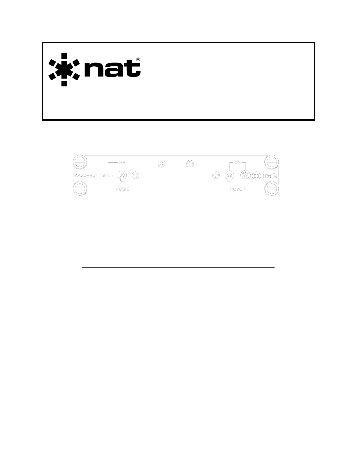
3.3 Switches and Indicators
Power
LED
Speaker
Switch
Power
Switch
3.3.1 Power Switch
To activate system, set the power switch to the ON position. The adjacent green LED
should illuminate.
3.3.2 Speaker Switch
With the SPKR switch in the MUSIC position, music audio will be heard over the
speaker. To turn off music audio, place switch into PA position. PA audio will be the
only audio delivered to the speaker. Music will be heard in the headset with the switch
in either position.
3.3.2.1 Music Operation
To listen to music or pre-recorded messages over the PA system, select the SPKR
switch to the MUSIC position and activate the ‘music’ source. Music volume can only
be adjusted at the music source. Music will automatically mute as described in section
3.4.
Apr 21, 2004 Page 3-1
ENG-FORM: 806-0106.DOT
CONFIDENTIAL AND PROPRIETARY TO NORTHERN AIRBORNE TECHNOLOGY LTD.
Page 28

AA20-431 Cabin PA System Manual SM22 Rev. 4.10
3.3.2.2 PA Operation
To broadcast voice messages over the PA system, select the SPKR switch to the PA
position, make the appropriate selection at the aircraft audio controller, then activate the
radio PTT switch. After the chime (see section 3.4), speak clearly and deliberately into
the microphone.
3.4 Chimes
The integrated chime capabilities of the AA20-431 provide advisory tones for typical
cabin/passenger applications.
3.4.1 No Smoking
When the ‘No Smoking’ keyline is activated, the music will mute and a chime will be
heard on the speaker and in the headset(s). The chime will last for 6 to 7 seconds, then
the music audio will slowly return to its previous level (2 to 4 seconds). The chime will
activate on keying (No Smoking ‘on’) and again on un-keying (No Smoking ‘off’).
3.4.2 Seatbelt
When the ‘Seatbelt’ keyline is activated, the music will mute and a chime will be heard
on the speaker and in the headset(s). The chime will last for 6 to 7 seconds, then the
music audio will slowly return to its previous level (2 to 4 seconds). The chime will
activate on keying (Seatbelt ‘on’) and again on un-keying (Seatbelt ‘off’).
3.4.3 Message
When the ‘Message’ keyline is activated, the music will mute and a chime will be heard
on the speaker and in the headset(s). The chime will last for 6 to 7 seconds, then the
music audio will slowly return to its previous level (2 to 4 seconds). The chime will
activate on keying and again on un-keying.
3.4.4 PA
When the ‘PA’ keyline is activated, the music will mute, a chime will be heard on the
speaker and in the headset and the mic amp will be turned on. The chime will last for 6
to 7 seconds, after which mic audio will be heard on the speaker and in the headset.
When the ‘PA’ keyline is de-activated, music audio will slowly return to its previous level
(2 to 4 seconds). The chime will activate only once on keying.
End of section 3.0
Page 3-2 Apr 21, 2004
ENG-FORM: 806-0106.DOT
CONFIDENTIAL AND PROPRIETARY TO NORTHERN AIRBORNE TECHNOLOGY LTD.
 Loading...