

Page 1
Installation and Operation Manual
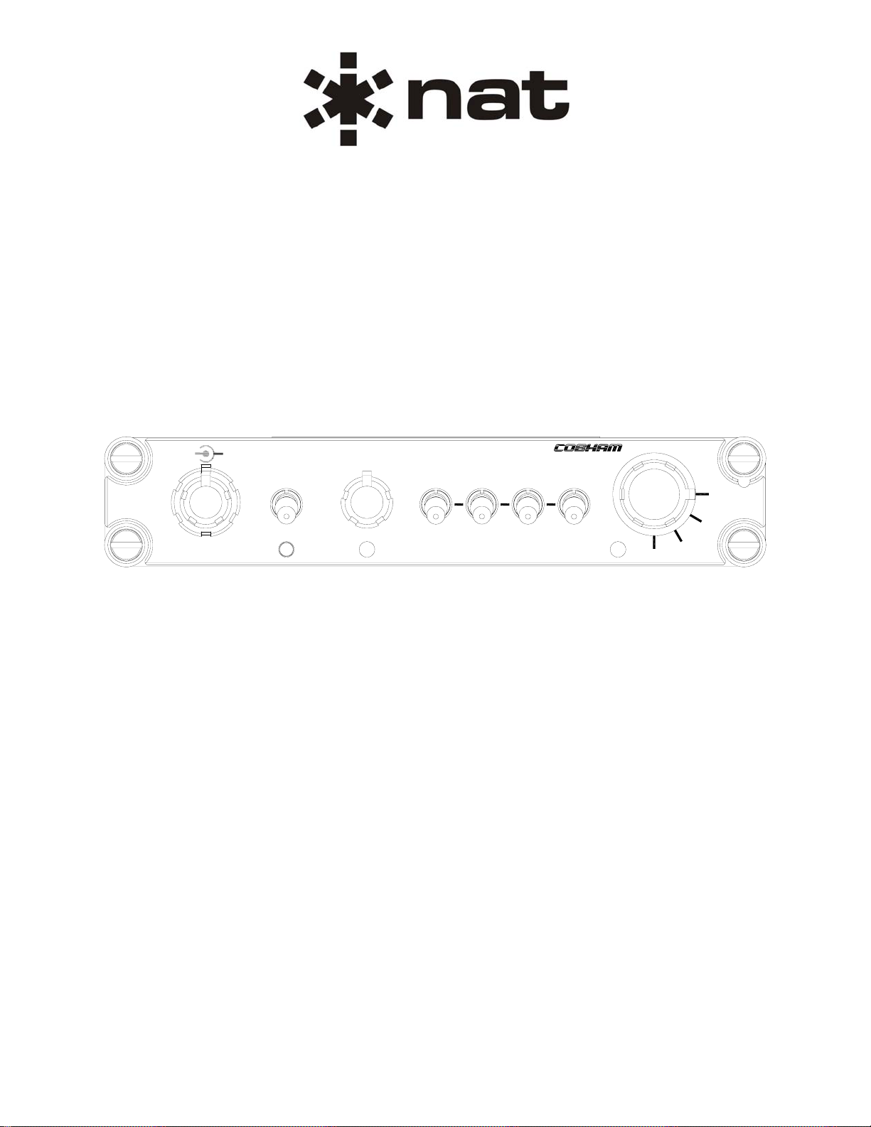
AA12S-600
Compact Stereo Audio Controller
AA12S
ICS
VOL
ISO
MUSIC
VOL
CALL
COM
NAV
21
COM
ADF
MKR
3
COM
TRFC
1
AUX
AUX
2
TX
VOX
KEYHOT
CREW
NORM
VOX
SM84
ISSUE 1.02
Northern Airborne Technology Ltd.
1925 Kirschner Road
Kelowna, BC, Canada.
V1Y 4N7
Telephone (250) 763-2232
Facsimile (250) 762-3374
Issued on the authority of Northern Airborne Technology Ltd.
Copyright 2009
PA
1
2
3
Page 2
AA12S-600 Compact Stereo Audio Controller
SM84 Installation and Operation Manual
Prepared By: Checked By: Approved By:
The status of this installation and operation manual is controlled by issue shown on the title page. The
status of each section is controlled by revision shown in the footer of each page. All revisions affecting
sections of this manual have been incorporated into the latest issue.
ISSUE/REVISION RECORD
Manual Issue
Number
Section
Revision Number
Revision Description Issue Date
1.02 Section 1 Rev: 1.01
Section 2 Rev: 1.02
1.01 Section 2 Rev: 1.01
Section 3 Rev: 1.01
1.00 Section 1 Rev: 1.00
Section 2 Rev: 1.00
Section 3 Rev: 1.00
Locking hardware updated. Oct 18, 2010
Latest drawings added
Rewritten in current format
Initial release Jun 29, 2009
May 10, 2010
Installation and Operation Manual Page ii
ENG-FORM: 820-0115.DOT
CONFIDENTIAL AND PROPRIETARY TO NORTHERN AIRBORNE TECHNOLOGY LTD.
Page 3

AA12S-600 Compact Stereo Audio Controller
SM84 Installation and Operation Manual
Table of Contents
Section Title Page
1. Description
1.1 Introduction 1-1
1.2 Product Description 1-1
1.3 Design Features 1-1
1.4 Specifications 1-2
1.4.1 Electrical Specifications 1-2
1.4.2 Physical Specifications 1-6
1.4.3 Environmental Specifications 1-7
2. Installation
2.1 Introduction 2-1
2.2 Unpacking and Inspection 2-1
2.2.1 Warranty 2-1
2.3 Continued Airworthiness 2-1
2.4 Installation Procedures 2-1
2.4.1 Warnings 2-2
2.4.2 Cautions 2-2
2.4.3 Cabling and Wiring 2-2
2.4.4 Post-Installation Checks 2-3
2.5 Adjustments and Connections 2-4
2.6 Accessories Required But Not Supplied 2-6
2.7 Installation Drawings 2-6
3. Operation
3.1 Introduction 3-1
3.2 General Information 3-1
3.3 Controls and Indicators 3-1
3.3.1 Receiver Audio 3-1
3.3.2 Transmit 3-2
3.3.3 MUSIC VOL 3-2
3.3.4 VOX and ICS VOL 3-2
3.3.5 CREW/ISO/NORM Modes 3-3
3.3.6 Emergency Mode 3-4
Installation and Operation Manual Page iii
ENG-FORM: 820-0115.DOT
CONFIDENTIAL AND PROPRIETARY TO NORTHERN AIRBORNE TECHNOLOGY LTD.
Page 4

AA12S-600 Compact Stereo Audio Controller
SM84 Installation and Operation Manual
Section 1 Description
1.1 Introduction
Information in this section consists of product description, design features and specifications for the
AA12S-600 Compact Stereo Audio Controller. All derivative product information shall be contained in the
applicable manual supplement, which may be obtained from Northern Airborne Technology Ltd. as
required.
Review all notes, warnings and cautions.
1.2 Product Description
The AA12S-600 is a compact Dzus-mounted audio controller with an integral 6 - place stereo voice
activated intercom. It provides intercom capabilities for two crew members (CREW 1 and CREW 2) and
four passengers (PAX 1 – PAX 4). Stereo music inputs are provided to connect either portable or fixed
entertainment systems to produce stereo headset output. Connectivity is provided for four COM
transceivers, nine COM/NAV receivers and four Direct Audio inputs. The fourth COM position can be
used to service a PA or additional AUX receiver.
1.3 Design Features
All microphones have individual VOX gating. Each VOX gate is activated by the corresponding ICS
keyline or when the microphone level exceeds the VOX threshold level. The VOX threshold level can be
set anywhere between live (HOT) and keyed (KEY).
The unit is supplied to suit a standard NAT bi-directional ICS audio TIE line for multi-unit interface
(configuration dependent). The ICS audio is muted to the applicable ICS group when an applicable user's
TX keyline is activated.
A stereo music input accepts audio signals from portable entertainment units, CD players or other
integrated on-board systems through the airframe connector J101. Stereo output delivers music to stereo,
or standard monaural, general aviation headsets (installation specific). Music muting occurs during radio
transmit or receive or intercom activity. The music mute level is adjustable for muting that occurs during
receive or intercom activity. The music is fully muted (disabled) during radio transmit.
The following audio levels can be adjusted at the time of installation, or during service by an approved
dealer, using individual level trimpots.
- Artificial Side Tone (AST ADJ) - Music Right Bass (MUSIC RIGHT BASS)
- Crew ICS Balance (CREW ICS BAL) - Music Right Treble (MUSIC RIGHT TREB)
- Direct Volume (DIR VOL) - PAX ICS Balance (PAX ICS BAL)
- Music Balance (MUSIC BAL) - Receive Balance (RX BAL)
- Music Left Bass (MUSIC LEFT BASS) - Receive Volume (RX VOL)
- Music Left Treble (MUSIC LEFT TREB) - Receive VOX (RX VOX)
- Music Mute Level (MUS MUTE LVL)
Section 1 Rev: 1.01 Issue 1 Page 1-1
ENG-FORM: 800-0115.DOT
CONFIDENTIAL AND PROPRIETARY TO NORTHERN AIR BORNE TECHNOLOGY LTD.
Page 5

AA12S-600 Compact Stereo Audio Controller
SM84 Installation and Operation Manual
1.4 Specifications
1.4.1 Electrical Specifications
Input Operating Voltage (28 Vdc Operation)
Normal Operating Conditions
Nominal +28.0 Vdc
Maximum +30.3 Vdc
Minimum +22.0 Vdc
Emergency +18.0 Vdc
Abnormal Operating Conditions
Nominal +28.0 Vdc
Maximum +32.2 Vdc
Minimum +20.5 Vdc
Input Current 500 mA maximum @ 28 Vdc
Input Operating Voltage (14 Vdc Operation)
Normal Operating Conditions
Nominal +14.0 Vdc
Maximum +15.1 Vdc
Minimum +11.0 Vdc
Abnormal Operating Conditions
Nominal +14.0 Vdc
Maximum +16.1 Vdc
Minimum +10.3 Vdc
Input Current 900 mA maximum @ 14 Vdc
Lighting (+28 Vdc)
Lights Input
Lighting (+14 Vdc)
Lights Input
Current 5 mA maximum
Current 5 mA maximum
Section 1 Rev: 1.01 Issue 1 Page 1-2
ENG-FORM: 800-0115.DOT
CONFIDENTIAL AND PROPRIETARY TO NORTHERN AIR BORNE TECHNOLOGY LTD.
Page 6

AA12S-600 Compact Stereo Audio Controller
SM84 Installation and Operation Manual
Input Signals
Note: All nominal values are listed with a ±10% tolerance.
Microphones
Quantity 6
Rated Level 250 mVrms nominal
Impedance 150 Ω nominal
Circuit Type Single ended
Mic Bias 12.0 Vdc
Receive Audio
Quantity 9
Rated Level 2.5 Vrms nominal
Impedance 1.0 kΩ nominal
Circuit Type Single ended
Emergency Receive Audio
Quantity 1
Rated Level 2.5 Vrms nominal
Impedance 1.1 kΩ nominal
Circuit Type Single ended
Direct Audio
Quantity 4
Rated Level 2.5 Vrms nominal
Impedance 1.0 kΩ nominal
Circuit Type Single ended
Direct Audio (Emergency Mode Operation)
Quantity 1 (DIR 1)
Rated Level 2.5 Vrms nominal
Impedance 1.0 kΩ nominal
Circuit Type Single ended
Music
Quantity 2
Rated Level 0.4 Vrms nominal
Impedance 10.0 kΩ nominal
Circuit Type Single ended
1
1
1
Assumes mono or stereo headphones of rated impedance attached to CREW 1 headphones output.
Section 1 Rev: 1.01 Issue 1 Page 1-3
ENG-FORM: 800-0115.DOT
CONFIDENTIAL AND PROPRIETARY TO NORTHERN AIR BORNE TECHNOLOGY LTD.
Page 7

AA12S-600 Compact Stereo Audio Controller
SM84 Installation and Operation Manual
Transmit Keylines
Quantity 3
Rated Level Active Low, <20 mA source current
ICS Keylines
Quantity 6
Rated Level Active Low, <20 mA source current
PAX Call Key
Quantity 1
Rated Level Active Low, <20 mA source current
Output Signals
Note: All nominal values are listed with a ±10% tolerance.
Headphones
Quantity 6 stereo outputs
Rated Level ≥100 mW (≥5.5 Vrms) into 300 Ω per channel stereo or
150 Ω mono
Impedance ≤35 Ω nominal
Circuit Type Single ended
Headphones (Emergency Mode Operation)
Quantity 1 stereo output (CREW 1)
Rated Level ≥0.25 mW into 300 Ω per channel stereo
Circuit Type Single ended
COM 1–4 Microphone
Quantity 4
Rated Level 250 Vrms nominal into 150 Ω
Impedance ≤140 Ω nominal
Circuit Type Single ended
Emergency COM Microphone
Quantity 1
Rated Level ≥190 mVrms nominal into 150 Ω
Circuit Type Single ended
2
2
Assumes microphone bias and terminating impedance provided by the Emergency Mode Transceiver.
Section 1 Rev: 1.01 Issue 1 Page 1-4
ENG-FORM: 800-0115.DOT
CONFIDENTIAL AND PROPRIETARY TO NORTHERN AIR BORNE TECHNOLOGY LTD.
Page 8

AA12S-600 Compact Stereo Audio Controller
SM84 Installation and Operation Manual
Keylines
Quantity 4
Rated Level <1.0 A
Circuit Type Grounded mechanical or solid state relay contact
Emergency Keyline
Quantity 1
Rated Level <1.0 A
Circuit Type Grounded mechanical or solid state relay contact
Bi-Directional Signals
NAT Inter-Communication System Tie Line
Audio Performance
As per RTCA DO-214, Sections 2.4.x. Product Classification 1b.
Rated Output Power ≥100 mW into 300 Ohm (each stereo channel)
Audio frequency Response
Spurious Response ≥50 dB of attenuation
Distortion ≤10% THD+N at Rated Output Power
≤3% THD+N at 10% Rated Output Power
Input-to-Output Crosstalk ≥55 dB of attenuation
and Bleed-Through Levels
Quantity 1
Rated Level 340 mVrms nominal
Impedance 2.0 kΩ nominal
Circuit Type Single ended
Transceiver Receive Audio ≤3dB variance from 300 - 6000 Hz
Transceiver Sidetone Audio ≤3dB variance from 300 - 6000 Hz
Transmit Mic Audio Out ≤3dB variance from 300 - 6000 Hz
Receiver Receive Audio ≤3dB variance from 300 - 6000 Hz
Intercom & ICS Tie Audio ≤3dB variance from 300 - 3000 Hz
Direct Audio ≤3dB variance from 300 - 6000 Hz
Music Audio ≤3dB variance from 150 - 15000 Hz
Section 1 Rev: 1.01 Issue 1 Page 1-5
ENG-FORM: 800-0115.DOT
CONFIDENTIAL AND PROPRIETARY TO NORTHERN AIR BORNE TECHNOLOGY LTD.
Page 9

AA12S-600 Compact Stereo Audio Controller
SM84 Installation and Operation Manual
Input-to-Input Crosstalk ≥60 dB of attenuation
Input-to-Microphone Output Crosstalk ≤1 mVrms
Stability and Short Circuit No visible spurious or sustained oscillations
≥50 dB attenuation on non-harmonically related
responses
Intermodulation Distortion ≥30 dB below
Audio Noise Without Signal ≥30 dB below
Signal Plus Noise Degradation >9 dB
Absolute (Envelope) Delay ≤10 ms
Output Regulation ≤3 dB variance
Audio Communication Loud & Clear
Transient Recovery ≤50 ms
1.4.2 Physical Specifications
Dimensions
Panel Height 1.140" (28.96 mm) maximum
Depth 5.680" (144.27 mm) maximum, behind panel
Panel Width 5.750" (146.05 mm) maximum
Width 5.020" (127.51 mm) maximum, behind panel
Weight 1.43 lbs (0.65 kg) maximum
Mounting Dzus rail, four fasteners, 5.365" horizontal spacing, 0.750"
Faceplate
Text and Lines white per FED-STD-595-37925
Background black per FED-STD-595-37038
Material manufactured from 0.250 ± 0.025" thick acrylic
Lighting laser-engraved acrylic edge lit with standard blue-white
vertical spacing
backlighting
Section 1 Rev: 1.01 Issue 1 Page 1-6
ENG-FORM: 800-0115.DOT
CONFIDENTIAL AND PROPRIETARY TO NORTHERN AIR BORNE TECHNOLOGY LTD.
Page 10

AA12S-600 Compact Stereo Audio Controller
SM84 Installation and Operation Manual
Material and Finish
Metal Components brushed aluminum with conversion coating
Connectors
Male 44 pin male high-density D-min connector with jackposts
Female 44 pin female high-density D-min connector with jackposts
1.4.3 Environmental Specifications
Temperature -20 to +55°C (operating)
-40 to +70°C (short-time operating)
-55 to +85°C (ground survival)
Altitude 25,000 feet maximum
Shock 6 g (operational, 11 ms)
20 g (crash safety impulse, 11 ms)
20 g (crash safety sustained, 3 s)
Vibration RTCA/DO-160E Section 8 Categories SBM and U2FF1
Section 1 ends
Section 1 Rev: 1.01 Issue 1 Page 1-7
ENG-FORM: 800-0115.DOT
CONFIDENTIAL AND PROPRIETARY TO NORTHERN AIR BORNE TECHNOLOGY LTD.
Page 11

AA12S-600 Compact Stereo Audio Controller
SM84 Installation and Operation Manual
Section 2 Installation
2.1 Introduction
Information in this section consists of unpacking and inspection procedures, installation procedure s, po stinstallation checks and installation drawings for the AA12S-600 Compact Stereo Audio Controller.
Review all notes, warnings and cautions.
2.2 Unpacking and Inspection
Unpack the equipment carefully and locate the warranty card. Inspect the unit visually for damage due to
shipping and report all such claims immediately to the carrier involved. Check that all items listed below
are present before proceeding and report any shortage immediately to your supplier:
- Warranty Card
- Operators Manual
- Certificate of Conformity or Release Certification
2.2.1 Warranty
All Northern Airborne Technology Ltd. products are warranted for 2 years from date of installation by an
authorized NAT dealer, to be free of defects in workmanship or performance. This warranty covers all
materials and labour, but is exclusive of any transport to deliver the defective unit to and from NAT or its
designated warranty repair center, or any labour to remove or re-install the defective unit in the aircraft.
Contact NAT for any questions regarding this warranty, its applicability to your units and/or for return
authorization. NAT is the final arbitrator concerning warranty administration. Units which have been
physically damaged, burned, immersed in water or otherwise abused beyond the scope of normal use will
not be considered for warranty. WARRANTY IS VOID UNLESS THE PRODUCT IS INSTALLED BY AN
AUTHORIZED NAT DEALER. Product for which a warranty card is not returned shall be warranted from
date of manufacture.
2.3 Continued Airworthiness
Maintenance of the AA12S-600 Compact Stereo Audio Controller is ‘on condition’ only. Periodic
maintenance of this product is not required.
2.4 Installation Procedures
Installation Notice
This product must be installed in accordance with the installation instructions provided in the latest issue
of this Installation and Operation Manual. Check the Publication Index at www.northernairborne.com for
the issue status of the manual. The latest issue of the manual may be downloaded from the same
website. All risk associated with installation of this product contrary to these instructions shall be the
responsibility of the installing agency.
Section 2 Rev: 1.02 Issue 1 Page 2-1
ENG-FORM: 805-0121.DOT
CONFIDENTIAL AND PROPRIETARY TO NORTHERN AIR BORNE TECHNOLOGY LTD.
Page 12

AA12S-600 Compact Stereo Audio Controller
2.4.1 Warnings
Set the headset volume control to the minimum volume setting prior to
conducting tests, and slowly increase the headset volume to a
2.4.2 Cautions
Do not bundle any lines from this unit with transmitter coax feed lines. Do not
bundle any audio, or DC power lines from this unit with 400 Hz synchro wiring
or AC power lines. Do not position this unit next to any device with a strong
alternating magnetic field such as an inverter, motor or blower, or significant
audio interference will result. In all installations, use shielded cable exactly as
Failure to follow the installation and wiring instructions provided in this manual
for power and ground connections, including the rating of the circuit breaker,
may lead to damage to the power input circuitry of the unit.
SM84 Installation and Operation Manual
WARNING:
High volume settings can cause hearing damage.
comfortable listening level.
CAUTION:
shown, and ground only as indicated.
2.4.3 Cabling and Wiring
All wire shall be selected in accordance with the original aircraft manufacturer's Maintenance Instructions
or AC43.13-1B Change 1, Paragraphs 11-76 through 11-78. Unshielded wire types shall qualify to
MIL-W-22759 as specified in AC43.13-1B Change 1, Paragraphs 11-85, 11-86, and listed in Table 11-11.
For shielded wire applications, use Tefzel MIL-C-27500 shielded wire with solde r sleeve s (fo r shield
terminations) to make the most compact and easily terminated interconnect. Follow the connector map in
Section 2.7 as required.
Allow 3" from the end of the shielded wiring to the shield termination to allow the connector hood to be
easily installed. Refer to the interconnect drawing in Section 2.7 for shield termination details. Note that
the hood is a "clamshell" hood, and is installed after the wiring is complete. Aircraft harnessing shall
permit the unit to be removed from the panel for easy access to all side adjustments. Do not mount the
unit until all adjustments have been performed.
Maintain wire segregation and route wiring in accordance with the original aircraft manufacturers
Maintenance Instructions.
Unless otherwise noted, all wiring shall be a minimum of 22 AWG. Refer to the Interconnect drawing for
additional specifications. Check that the ground connection is clean and well secured, and that it shares
no path with any electrically noisy aircraft accessories such as blowers, turn and bank instruments or
similar loads. Power to this unit must be supplied from a separate circuit breaker or fuse (fast blow), and
not attached to any other circuit breaker without additional protection. Verify that the selected circuit
breaker size and wire gauge are adequate for the installation using the techniques specified in
AC43.13-1B Change 1, Paragraphs 11-47 through 11-51 and 11-66 through 11-69.
Section 2 Rev: 1.02 Issue 1 Page 2-2
ENG-FORM: 805-0121.DOT
CONFIDENTIAL AND PROPRIETARY TO NORTHERN AIR BORNE TECHNOLOGY LTD.
Page 13

AA12S-600 Compact Stereo Audio Controller
SM84 Installation and Operation Manual
2.4.4 Post-Installation Checks
2.4.4.1 Voltage/Resistance Checks Do not attach the AA12S-600 until the following conditions are met.
Check the following:
a) Check P101 pin <1> for avionics buss voltage.
b) For 28 V lighting input, check P101 pin <8> for avionics lighting buss voltage relative to
ground (with lighting on).
c) For 14 V lighting input, check P101 pin <23> for avionics lighting buss voltage relative to
ground (with lighting on).
d) Check P101 pins <16>, <37> and <38> for continuity to ground (les s than 0.5Ω).
e) Check P101 pins <9>, <10>, <11>, <12>, <13>, <14>, <15> and <24> for conti nuity to
ground when the relevant switch is closed.
f) Check P102 pins <16> and <31> for continuity to ground when the relevant switch is closed.
2.4.4.2 Power On Checks
Power up the aircraft’s systems and confirm normal operation of all functions of the AA12S-600. Refer to
Section 3 (Operation) for specific operational details.
a) Begin with only the CREW 1 headset installed. Confirm correct radio operation, both receive
and transmit. Check radio audio inputs and selection of same.
b) If there is a music source in the system turn it on and verify that music is removed in the
CREW and ISO modes. Check for proper mute operation.
c) Unusual buzzes, hums or other background audio are symptomatic of multiple grounds, or
noisy external systems such as blowers or pumps sharing wiring with the audio system.
Failure to key or correctly modulate a transmitter is often the result of forgetting to connect all
required grounds to the radio or external audio system.
d) Check the ICS modes (NORM, CREW, and ISO) and Emergency operation. Confirm that the
ICS is disabled in the CREW 1 headset in ISO mode.
e) Plug in the CREW 2 headset. Check for correct ICS and transmit operation. Check that
CREW 2 loses transmit capability in ISO mode.
f) Plug in the PAX 1 headset. Check for correct ICS and transmit operation. Check that PAX 1
loses transmit capability in CREW and ISO modes.
g) Plug in any remaining headsets, and check for correct ICS operation.
h) To verify proper operation, all functions and levels shall be checked in-flight.
i) Check preset adjustments are completed before aircraft departure.
Upon satisfactory completion of all performance checks, make all required log book entries, electrical
load, weight and balance amendments and other documentation as required by your local regulatory
agency before releasing the aircraft for service.
Section 2 Rev: 1.02 Issue 1 Page 2-3
ENG-FORM: 805-0121.DOT
CONFIDENTIAL AND PROPRIETARY TO NORTHERN AIR BORNE TECHNOLOGY LTD.
Page 14

AA12S-600 Compact Stereo Audio Controller
SM84 Installation and Operation Manual
2.5 Adjustments and Connections
The unit is shipped from the factory with all internal adjustments set to the normal test levels. Once
installed in the aircraft, it may be desirable to change some of these settings to best suit the local
operating environment. The internal adjustments are located on the sides of the unit.
TIE
ICS
PAX
ICS
LOAD
BAL
CREW
ICS
BAL
AST
ADJ
Figure 1: Internal Adjustments – Left Side View
PA
OPT
MUS
AST
MUTE
LVL
MUSIC
RIGHT
VOXRX
BALRX
VOLRX
DIR
LEFT BAL
VOL
Figure 2: Internal Adjustments – Right Side View
PAX ICS BAL
The PAX ICS audio can be panned left or right using the PAX ICS BAL potentiometer.
ICS TIE LOAD
The ICS Tie Load is enabled at factory by setting the switch to the up position. Set the switch to the down
position if the AA12S-600 ICS Tie Line is connected to an external ICS tie line.
CREW ICS BAL
The CREW ICS audio can be panned left or right using the CREW ICS BAL potentiometer.
AST ADJ
The Artificial Sidetone level can be set between -19 and 0 dB from the set RX Volume level by adjusting
the AST ADJ potentiometer. The factory preset level is approximately -6 dB.
PA OPT
COM 4/PA auto-receive and sidetone audio can be disabled by setting the PA OPT switch to the down
position. This enables the COM 4/AUX 1 RX input to be used for a separate receiver.
Section 2 Rev: 1.02 Issue 1 Page 2-4
ENG-FORM: 805-0121.DOT
CONFIDENTIAL AND PROPRIETARY TO NORTHERN AIR BORNE TECHNOLOGY LTD.
Page 15

AA12S-600 Compact Stereo Audio Controller
SM84 Installation and Operation Manual
AST OPT
Artificial Sidetone can be enabled for the COM 4/PA transceiver position by setting the AST OPT switch
to the down position.
MUS MUTE LVL
The Music Mute Level adjustment sets the level of music attenuation during radio or intercom activity.
Adjusting the MUS MUTE LVL potentiometer cw increases the depth of muting while ccw decreases the
depth of muting.
RX VOX
The RX VOX potentiometer sets the threshold at which the applicable RX audio signals are enabled onto
the appropriate user headphones. The threshold level can be set between live (fully ccw) and -8.5dB from
rated input (fully cw)
RX BAL
The summed Auto-Receive, RX, DIR and Artificial Sidetone audio can be panned left or right using the
RX BAL potentiometer.
RX VOL
The volume level of the summed Auto-Receive, RX, and Artificial Sidetone audio can be adjusted using
the RX VOL potentiometer.
DIR VOL
The direct audio volume level can be adjusted using the DIR VOL potentiometer.
MUSIC LEFT TREB
The left channel music audio treble can be adjusted ±10 dB at 15000 Hz using the MUSIC LEFT TREB
potentiometer.
MUSIC LEFT BASS
The left channel music audio bass can be adjusted ±9 dB at 100 Hz using the MUSIC LEFT BASS
potentiometer.
MUSIC BAL
The music audio can be panned left or right using the MUSIC BAL potentiometer.
MUSIC RIGHT TREB
The right channel music audio treble can be adjusted ±10 dB at 15000 Hz using the MUSIC RIGHT TREB
potentiometer.
MUSIC RIGHT BASS
The right channel music audio bass can be adjusted ±9 dB at 100 Hz using the MUSIC RIGHT BASS
potentiometer.
Section 2 Rev: 1.02 Issue 1 Page 2-5
ENG-FORM: 805-0121.DOT
CONFIDENTIAL AND PROPRIETARY TO NORTHERN AIR BORNE TECHNOLOGY LTD.
Page 16

AA12S-600 Compact Stereo Audio Controller
SM84 Installation and Operation Manual
2.6 Accessories Required But Not Supplied
Installation kit p/n D44P44SL-IKC (crimp) is required to complete the installation. The kit consists of the
D44SL-IKC and the D44PL-IKC.
D44SL-IKC consists of
Quantity Description NAT Part No.
1 D-min 44 Socket Housing 20-20-044
44 Mini D Crimp Socket 20-26-703
1 Jack Screw Set 20-27-002
1* Lock Clip Set 20-27-004
1 25 pin Connector Hood 20-29-026
D44PL-IKC consists of
Quantity Description NAT Part No.
1 D-min 44 Socket Housing 20-20-044
44 Mini D Crimp Pin 20-26-704
1 Jack Screw Set 20-27-002
1* Lock Clip Set 20-27-004
1 25 pin Connector Hood 20-29-026
* - Not required for the AA12S-6xx
2.7 Installation Drawings
DOCUMENT REV. DESCRIPTION TYPE
AA12S-600
AA12S\600\403-0 1.00 Compact Stereo Audio Controller Interconnect (3 sheets)
AA12S\600\405-0 1.00 Compact Stereo Audio Controller Connector Map
AA12S\600\922-0 1.20 Compact Stereo Audio Controller Mechanical Installation
Section 2 ends following the above documents
Section 2 Rev: 1.02 Issue 1 Page 2-6
ENG-FORM: 805-0121.DOT
CONFIDENTIAL AND PROPRIETARY TO NORTHERN AIR BORNE TECHNOLOGY LTD.
Page 17

Page 18

Page 19

Page 20

Page 21

 Loading...