

Page 1
SM3110
3110
Audio Control Panel
INSTALLATION AND OPERATION MANUAL
REV 4.00 August 25, 2005
Northern Airborne Technology Ltd.
1925 Kirschner Road
Kelowna, BC, Canada.
V1Y 4N7
Telephone (250) 763-2232
Facsimile (250) 762-3374
Copyright 2005 by Northern Airborne Technology
CONFIDENTIAL AND PROPRIETARY TO NORTHERN AIRBORNE TECHNOLOGY LTD.
Page 2

Page 3
SM3110 Rev. 4.00 3110 Audio Control Panel Manual
Performed at factory
Performed at factory
Periodically NAT will release manual amendments. In order to maintain the most
accurate and up to date manual these amendments should be carried out immediately
upon receipt and recorded on the following amendment record.
AMENDMENT RECORD
Amendment
Number
Amendment
Date
Note: Revision 4.00 is the first public release of this document
Section(s)
Changed
Date
Entered
Entered By
1 Sep 27,05 2
2 Nov 21,06 1,2
Aug 25, 2005 Page ii
ENG-FORM: 820-0109.DOT
CONFIDENTIAL AND PROPRIETARY TO NORTHERN AIRBORNE TECHNOLOGY LTD.
Insert any Amendment Instruction sheets after this page.
Page 4

Page 5
INSTALL_OPS
MANUAL AMENDMENT
Manual: SM3110 Amendment #: 2
Document # SM3110\Install_Ops\809-0002 Amendment Date: Nov 21, 2006
The purpose of this amendment is to add the most recent parts to the Unit
Nomenclature, record the installation kit, and add the custom Mechanical Installation
drawing to the manual.
Amendment Instructions:
1
1-9 Rev 4.00 1-9 Rev 4.00 Amendment 2
2-5 Rev 4.00 Amendment 1 2-5 Rev 4.00 Amendment 2
2
3110\922-0 Rev 1.01 3110\952-0 Rev 1.00
Note: Ensure that all drawings are inserted in the order shown on the latest drawing lists.
Remove Drawings (Section 2) Replace or add Drawings (Section 2)
3 Update the Amendment Record sheet at the front of the manual.
4 Insert this page into the manual after the Amendment Record sheet (page ii).
Manual Amendment ends after the following amended pages
Remove Pages Replace With Pages
Amendment #2 Nov 21, 2006 Page 1
ENG-FORM: 809-0109.DOT
CONFIDENTIAL AND PROPRIETARY TO NORTHERN AIRBORNE TECHNOLOGY LTD.
Page 6

Page 7
INSTALL_OPS
MANUAL AMENDMENT
Manual: SM3110 Amendment #: 1
Document # SM3110\Install_Ops\809-0001 Amendment Date: Sep 27, 2005
The purpose of this amendment is to update the mechanical installation drawing.
Amendment Instructions:
1
2
Note: Ensure that all drawings are inserted in the order shown on the latest drawing lists.
Remove Drawings (Section 2) Replace With (Section 2)
3 Update the Amendment Record sheet at the front of the manual.
4 Insert this page into the manual after the Amendment Record sheet (page ii).
Manual Amendment ends after the following amended pages
Remove Pages Replace With Pages
2-5 Rev 4.00 2-5 Rev 4.00 Amendment #1
3110\100\922-0 Rev 1.00 3110\100\922-0 Rev 1.01
Amendment #1 Sep 27, 2005 Page 1
ENG-FORM: 809-0109.DOT
CONFIDENTIAL AND PROPRIETARY TO NORTHERN AIRBORNE TECHNOLOGY LTD.
Page 8

Page 9

SM3110 Rev. 4.00 3110 Audio Control Panel Manual
Table of Contents
Section Title Page
1 Description
1.1 Introduction 1-1
1.2 Purpose of Equipment 1-1
1.3 Features 1-1
1.4 Specifications 1-2
1.4.1 Electrical Specifications 1-2
1.4.2 Physical Specifications 1-8
1.4.3 Environmental Specifications 1-8
1.5 Unit Nomenclature 1-9
2 Installation
2.1 Introduction 2-1
2.2 Unpacking and Inspection 2-1
2.2.1 Warranty 2-1
2.3 Installation Procedures 2-1
2.3.1 Warnings 2-1
2.3.2 Cautions 2-2
2.3.3 Cabling and Wiring 2-2
2.3.4 Mounting 2-2
2.3.5 Installation Notes 2-3
2.3.6 Post-Installation Checks 2-4
2.4 Continued Airworthiness 2-4
2.5 Accessories Required But Not Supplied 2-5
2.6 Installation Drawings 2-5
3 Operation
3.1 Introduction 3-1
3.2 General 3-1
3.3 Operation 3-1
3.3.1 Power Up/Down 3-1
3.3.2 Transmitter Selection 3-2
3.3.3 Receiver Selection 3-2
3.3.4 INPH (Interphone) Volume Control 3-3
3.3.5 Navigation Filter Selection 3-3
3.3.6 ST (Sidetone) Volume Control 3-3
3.3.7 VOX Selection 3-3
Aug 25, 2005 Page iii
ENG-FORM: 820-0109.DOT
CONFIDENTIAL AND PROPRIETARY TO NORTHERN AIRBORNE TECHNOLOGY LTD.
Page 10

Page 11

SM3110 Rev. 4.00 3110 Audio Control Panel Manual
Section Title Page
3.3.8 MUTE (Marker Beacon Mute) Selector 3-4
3.3.9 SPKR (Speaker) Control 3-4
3.3.10 HDPH (Headphone) Control 3-4
3.3.11 Power Off Emergency Mode 3-4
3.3.12 Service Interphones 3-5
3.3.13 Passenger Address 3-5
3.3.14 PTT 3-5
3.4 External Control Functions 3-5
3.4.1 Emergency Mode Switch and Annunciator 3-5
3.4.2 Oxygen Mask Mode 3-6
3.4.3 Cabin Call Tone 3-6
3.4.4 Speaker Mute (AUX MUTE) 3-6
3.4.5 Aural Warning Volume 3-6
3.4.6 Cockpit Voice Recorder (CVR) Audio output 3-7
3.4.7 Annunciator Test 3-7
3.4.8 Aural Warning Priority 3-7
Aug 25, 2005 Page iv
ENG-FORM: 820-0109.DOT
CONFIDENTIAL AND PROPRIETARY TO NORTHERN AIRBORNE TECHNOLOGY LTD.
Page 12

Page 13

SM3110 Rev. 4.00 3110-100 Audio Control Panel Manual
Section 1 Description
1.1 Introduction
This manual contains information on the 3110-100 Audio Control Panel (ACP). All
derivative products will be covered by manual supplements, which can be obtained from
NAT as required.
Information in this section consists of purpose of equipment, features and specifications.
1.2 Purpose of Equipment
The model 3110-100 Audio Control Panel is a self-contained audio selection and mixing
panel compatible with the Rockwell Collins Pro Line 21 series radios (or equivalent).
Each 3110-100 provides selection of multiple transceivers, receivers, interphone circuits
and auxiliary functions from a basic front panel interface. The interface between the
radios and the 3110-100 and between multiple 3110 units is analog only.
1.3 Features
The 3110-100 ACP provides analog audio interfaces and Push-To-Talk (PTT) discretes
to the Rockwell Collins Pro Line 21 radios. The 3110-100 is an analog audio controller
with additional features for mixing and control of Aural Warning muting, front panel
control and audio amplification for headphone, speaker, CVR, interphone, radio
transmitter/receiver audio and keying.
Analog interfacing provides flight station interphone access, service interphone and radio
receiver/transceiver features. Various other analog features are also provided, including a
cockpit voice recorder output and emergency mode radio I/O. All interfacing is
accomplished through a 128 pin MIL-DTL-38999 Series II connector with alternate keying.
The 3110-100 converts standard aircraft power for its own use through its internal
power supply.
The 3110-100 provides:
• Three-position Service Interphone with ability for the pilot to connect to the Service
Interphone via the CAB function, with Cabin Call to alert the pilot.
• Transmit selection for four radios plus CAB (COM6) and PA, receive audio selection
for four Comm radios plus CAB (COM6), PA, and seven Navigation radios.
Individual receive audio volume control is provided for each receiver.
Aug 25, 2005 Page 1-1
ENG-FORM: 800-0108.DOT
CONFIDENTIAL AND PROPRIETARY TO NORTHERN AIRBORNE TECHNOLOGY LTD.
Page 14

3110-100 Audio Control Panel Manual SM3110 Rev. 4.00
• Dynamic VOX system for noise reduction. This system removes unwanted
background noise that might be picked up by the pilot’s microphone, and prevents it
from entering the interphone channel.
• Protection circuits to help prevent accidental damage from overvoltage and reverse
voltage conditions.
• Five direct audio Aural Warning inputs with priority for inputs 1 and 2.
• Automatic fail-safe operation in the event of a power failure.
• A Voice/Ident filter for the NAV and ADF inputs.
• A MKR mute function to temporarily mute the marker beacon audio.
• A CVR audio output, which includes pilot Hot Mic audio.
• An OXY mode to minimise pilot workload when switching to use of an oxygen mask.
• Noise gating to minimise unwanted audio noise at the pilot headset and cockpit
speaker outputs.
1.4 Specifications
1.4.1 Electrical Specifications
1.4.1.1 Power Input
Operating Voltages:
Maximum +30.3 Vdc
Nominal +28.0 Vdc
Minimum +22.0 Vdc
Emergency +18.0 Vdc
Annunciator Lighting 0 - 28 Vdc
Backlighting 0 - 5 Vdc
1.4.1.2 Input Signals
Microphone: (BOOM/MASK MIC, HAND MIC, SVC MIC)
Specification TSO-C58a (RTCA/DO-170)
Type Differential, AC coupled, transformerless
Impedance 150 Ω
Page 1-2 Aug 25, 2005
ENG-FORM: 800-0108.DOT
CONFIDENTIAL AND PROPRIETARY TO NORTHERN AIRBORNE TECHNOLOGY LTD.
Page 15

SM3110 Rev. 4.00 3110-100 Audio Control Panel Manual
Input Level, Rated 250 mVrms
Dynamic Range 20 mVrms - 1.5 Vrms (MIC input to COM output only)
DC Bias: 22 ±5 mA at 15 Vdc
Keyline: (RADIO PTT, CKPT INPH PTT, HAND MIC
PTT, SVC PTT)
Level: Open (≥100 kΩ) (Inactive)
GND (<30 Ω) (Active)
Source Current: <20 mA
Discrete Input: (AUX MUTE INHIBIT, AUX LEVEL, AUX MUTE
SWITCH, CABIN CALL SW, EMER MODE IN,
OXY SWITCH, ANNUNC TEST)
Level: 18.5 to 36 V (HI)
<3.5 V (LO)
Impedance: ≥100 kΩ, AUX MUTE INHIBIT ≥ 50 kΩ
Source Current: <20 mA
Analog Receiver/Sidetone: (RCVR, SDTN)
Type: Differential, AC coupled, transformerless
Input Level: See Table 1
Impedance: 2 kΩ single ended (LO grounded), or
4 kΩ differential
Analog Aural Warning: (AUX)
Type: Differential, AC coupled, transformerless
Input Level: See Table 2
Impedance: 10 kΩ single ended (LO grounded) or
20 kΩ differential
Priority Detection Threshold: 90 ± 20 mVrms
EMER Receiver: (VHF BKUP RX)
Type: Single ended, transformerless, passive resistor
bypass
Input level: 7.75 Vrms nominal
EMER Aural Warning: (AUX BKUP)
Type: Single ended, transformerless, passive resistor
bypass
Input level: See Table 2 in section 1.4.1.3
Aug 25, 2005 Page 1-3
ENG-FORM: 800-0108.DOT
CONFIDENTIAL AND PROPRIETARY TO NORTHERN AIRBORNE TECHNOLOGY LTD.
Page 16

3110-100 Audio Control Panel Manual SM3110 Rev. 4.00
1.4.1.3 Output Signals
Headphone: (PLT HDPH, SVC HDPH)
Headphone Type Single ended, AC coupled, transformerless,
short circuit protected
Impedance: ≤20 Ω
Output load: 150 Ω Minimum, 1 µF Maximum
Volume range: 39 ±5 dB (PLT HDPH only)
Rated power:
PLT HDPH: 240 mW into 150 Ω (6.0 ±1.0 Vrms)
SVC HDPH: 6.6 mW into 150 Ω (1.0 ±0.1 Vrms)
Distortion: <2% nominal
Cabin Call Tone Level: 2.5 ±1.0 Vpp
EMER Mode: -20 ±3 dB relative to input
Microphone: (COM MIC)
Microphone Type: Differential, AC coupled, transformerless, short
circuit protected
Impedance: 100 Ω ±20% (when keyed)
Output Load: 150 Ω ±20%
Dynamic Range: 20 mVrms to 1.5 Vrms, (2.12 V peak)
Nominal: 350 ±50 mVrms
Rated Power: 15 mW into 150 Ω (1.5 ±0.05 Vrms)
Distortion: <2% nominal
Passenger Address: (PA MIC)
Type: Differential, AC coupled, transformerless, short
circuit protected
Impedance: 100 Ω ±20% (when keyed)
Output load: 150 Ω ±20%
Dynamic Range: 10 to 750 mVrms
Nominal: 175 ±25 mVrms
Rated power: 3.8 mW into 150 Ω (750 ±25 mVrms)
Speaker: (CKPT SPKR)
Type: AC coupled, bridge output, short circuit
protected
Page 1-4 Aug 25, 2005
ENG-FORM: 800-0108.DOT
CONFIDENTIAL AND PROPRIETARY TO NORTHERN AIRBORNE TECHNOLOGY LTD.
Distortion: <2% nominal
Page 17

SM3110 Rev. 4.00 3110-100 Audio Control Panel Manual
Load Impedance: ≥8 Ω
Output Impedance: ≤4 Ω
Volume range: 39 ±5 dB
Rated power: 8 W into 8 Ω (8 ±1 Vrms)
Distortion: <2% nominal.
Cabin Call Tone Level: 3.8 ±1.2 Vpp
Keyline: (COM PTT, PA PTT, VHF BKUP PTT)
Level: Open (≥100 kΩ) (Inactive)
GND (<30 Ω) (Active)
Sink Current: <20 mA
Discrete Output
: (EMER MODE OUT, AUX MUTE ANNUNC,
PA STEREO MUTE)
Level: 18.5 to 36 V (HI)
<3.5 V (LO)
Sink Current: <100 mA
Cockpit Voice Recorder
: (CVR)
Type: Differential, AC coupled, transformerless, short
circuit protected
Impedance: <600 Ω
Load Impedance: 5000 Ω
Level: 40 mVrms to 3.0 Vrms
Output power: 1.8 mW into 5000 Ω (3.0 ±0.2 Vrms)
Distortion: <2% nominal.
EMER Mode: -20 ±3 dB relative to input
EMER Microphone
: (VHF BKUP TX)
Type: Single ended, transformerless, passive bypass
through relay contacts.
Load Impedance: 150 Ω
Aug 25, 2005 Page 1-5
ENG-FORM: 800-0108.DOT
CONFIDENTIAL AND PROPRIETARY TO NORTHERN AIRBORNE TECHNOLOGY LTD.
Page 18

3110-100 Audio Control Panel Manual SM3110 Rev. 4.00
Pin Name Signal Name Source
Nominal
Level
RCVR1 COM1 RECEIVER TRANSMITTER 7.75 Vrms
RCVR2 COM2 RECEIVER TRANSMITTER 7.75 Vrms
RCVR3 COM3 RECEIVER TRANSMITTER 7.75 Vrms
RCVR4 HF RECEIVER TRANSMITTER 7.75 Vrms
RCVR5
COM5
RECEIVER TRANSMITTER 7.75 Vrms
(SPARE)
RCVR6
COM6 RECEIVER TRANSMITTER 7.75 Vrms
(OPTION)
RCVR7 PA PA RECEIVER TRANSMITTER 3.88 Vrms
RCVR8 NAV1 VOR/LOC RECEIVER 7.75 Vrms
RCVR9 NAV2 VOR/LOC RECEIVER 7.75 Vrms
RCVR10 DME1 DME RECEIVER 5.30 Vrms
RCVR11 DME2 DME RECEIVER 5.30 Vrms
RCVR12 MKR MARKER BEACON RECEIVER 5.48 Vrms
RCVR13 ADF1 ADF RECEIVER 5.48 Vrms
RCVR14 ADF2 ADF RECEIVER 5.48 Vrms
SDTN1 COM1 SDTN RECEIVER SIDETONE 5.48 Vrms
SDTN2 COM2 SDTN RECEIVER SIDETONE 5.48 Vrms
SDTN3 COM3 SDTN RECEIVER SIDETONE 5.48 Vrms
SDTN4 COM4 SDTN RECEIVER SIDETONE 5.48 Vrms
SDTN5 COM5 SDTN RECEIVER SIDETONE 5.48 Vrms
SDTN6
(OPTION)
COM6 SDTN
(OPTION)
RECEIVER SIDETONE 5.48 Vrms
SDTN7 PA SDTN PA RECEIVER SIDETONE 3.88 Vrms
Source
Impedance
600 Ω
600 Ω
600 Ω
600 Ω
600 Ω
600 Ω
600 Ω
600 Ω
600 Ω
600 Ω
600 Ω
600 Ω
600 Ω
600 Ω
600 Ω
600 Ω
600 Ω
600 Ω
600 Ω
600 Ω
600 Ω
Table 1: Audio Input Signals –
Adjustable by Individual and General Volume Controls
Pin
Signal
Name
Name
AUX1 AUX1
Source
TAWS AURAL
Nominal
Level
2.5 Vrms
Source
Impedance
HDPH
Output Level
SPKR
Output Level
600 Ω 2.5 ±0.5 Vrms 2.5 ±0.5 Vrms
WARNING
AUX2 AUX2
HEADS UP AURAL
2.5 Vrms
600 Ω 2.5 ±0.5 Vrms 2.5 ±0.5 Vrms
WARNING
AUX3 AUX3 TCAS AURAL WARNING 2.0 Vrms
AUX4 AUX4
CHECK LIST AURAL
1.75 Vrms
600 Ω 2.5 ±0.5 Vrms 2.5 ±0.5 Vrms
600 Ω 2.5 ±0.5 Vrms 2.5 ±0.5 Vrms
WARNING
AUX5 AUX5
CHECK LIST AURAL
1.75 Vrms
600 Ω 2.5 ±0.5 Vrms 2.5 ±0.5 Vrms
WARNING
Table 2: Audio Input Signals –
Levels Not Adjustable by 3110-100 Controls
Page 1-6 Aug 25, 2005
ENG-FORM: 800-0108.DOT
CONFIDENTIAL AND PROPRIETARY TO NORTHERN AIRBORNE TECHNOLOGY LTD.
Page 19

SM3110 Rev. 4.00 3110-100 Audio Control Panel Manual
1.4.1.4 Bidirectional Signals
Service Interphone
: (SVC INPH I/O)
Type Differential, AC coupled, transformerless, short
Impedance 300 Ω
Dynamic Range 20 mVrms to 1.1Vrms, (1.55 V peak) into 300 Ω
Rated power 4.0 mW into 300 Ω (1.1 ±0.2 Vrms)
circuit protected
Flight Station (Cockpit) Interphone: (CKPT INPH I/O)
Type Differential, AC coupled, transformerless, short
circuit protected
Impedance 300 Ω
Dynamic Range 20 mVrms to 1.1 Vrms, (1.55 V peak) into 300 Ω
Rated power 4.0 mW into 300 Ω (1.1 ±0.2 Vrms)
OXY I/O DISCRETE Internally connected to OXY SWITCH input
Sink current 100 mA Max.
1.4.1.5 Audio Performance: (TSO-C50c RTCA DO-214 class 1b)
Audio Frequency Response
All outputs except CVR: ≤3 dB variation from 300 Hz - 6000 Hz
CVR output with boom/mask mic input and VOX on:
≤3 dB variation from 300 Hz - 4500 Hz
Spurious Responses ≤-50 dB from rated output
Distortion ≤10% @ rated power
≤3% @ 10% rated power
Input Impedance Within ±45° of zero phase
Output Impedance ≤2.5 times manufacturer’s specification
Volume Controls 39 ±5 dB range.
Output Regulation ≤10% Distortion when output load is changed
from 75% to 400% of rated load impedance
Output Power ≤3 dB variation for Interphone and Isolation
Amplifiers
≤7 dB variation for amplifiers whose rated
output impedance is equal to that of the rated
load impedances
Input-Output Crosstalk and Bleed-Through Levels
≤-55 dB
Input-Input Crosstalk ≤-60 dB
Aug 25, 2005 Page 1-7
ENG-FORM: 800-0108.DOT
CONFIDENTIAL AND PROPRIETARY TO NORTHERN AIRBORNE TECHNOLOGY LTD.
Page 20

3110-100 Audio Control Panel Manual SM3110 Rev. 4.00
Input-Mic Output Crosstalk ≤1.0 mVrms
Intermodulation Distortion ≤-30 dB (except for BOOM/MASK MIC to PLT
HDPH / CKPT INPH / CVR / CKPT SPKR)
≤-15 dB (BOOM/MASK MIC to PLT HDPH /
CKPT INPH / CVR / CKPT SPKR)
Audio Noise Without Signal ≤-50 dB from rated output
Signal Plus Noise Degradation >9 dB signal plus noise to noise
Absolute (Envelope) Delay ≤10 msec
Differential Delay ≤9dB from 300 Hz to 6000 Hz
Transient Recovery ≤50 msec
Audio Communication Loud and clear
1.4.2 Physical Specifications
Height: 3.00" (76.0 mm) max (from front panel lower
edge to front panel upper edge)
Width: 4.98" (126.5 mm) max. (behind panel)
Depth: 6.50" (165 mm) max. (from back of front panel
mounting plate to back of unit connector)
Weight 3.1 lbs (1.4 kg)
Mounting Dzus Rail (four fasteners)
Connector One MIL-DTL-38999 type
(Manufacturer p/n 91-569749-35E)
Material/Finish Aluminum with chromate conversion
1.4.3 Environmental Specifications
Temperature
Low Operating -55° C
Short-time Low Op -55° C
High Operating +70° C
Short-time High Op +70° C
Ground Survival Low -55° C
Ground Survival High +85° C
Altitude +55,000 ft
Humidity 95%
Shock 6 g for 11 ms in all axes
Page 1-8 Aug 25, 2005
ENG-FORM: 800-0108.DOT
CONFIDENTIAL AND PROPRIETARY TO NORTHERN AIRBORNE TECHNOLOGY LTD.
Page 21

SM3110 Rev. 4.00 3110-100 Audio Control Panel Manual
Qualification:
DO-160D Environmental Categories:
[(A2)(F2)–]BAB[(TBB1R)(UF)]XXXXXXZ[BZ]AZA[RR]H[A2C3X]XXA.
DO-160E Environmental Categories:
[(A2)(F2)–]BAB[(RBB1)(HR)(U2F)]XXXXXXZ[BZ]AZ[AC][RR]H[A2C3X]XXAX.
1.5 Unit Nomenclature
Collins Part # NAT Part # COM1 COM2 COM3 HF COM5 CAB PA ADF1 ADF2
866-0018-010
3110-000
♦ ♦
♦ ♦
866-0018-020
866-0018-030
866-0018-040
866-0018-015
866-0018-035
866-0018-160 3110-100
866-0018-150 3110-101
866-0018-140 3110-102
866-0018-130 3110-103
866-0018-120 3110-104
866-0018-110 3110-105
866-0018-100 3110-106
866-0018-090 3110-107
866-0018-080 3110-108
866-0018-070 3110-109
866-0018-060 3110-110
3110-001
3110-002
3110-003
3110-004
3110-005
♦ ♦
♦ ♦
♦ ♦
♦ ♦
♦ ♦
♦
♦
♦
♦ ♦ ♦ ♦
♦ ♦ ♦ ♦
♦ ♦ ♦
♦ ♦ ♦
♦ ♦
♦ ♦
♦ ♦
♦ ♦
♦
♦
♦ ♦ ♦ ♦
♦ ♦ ♦ ♦
♦ ♦ ♦
♦ ♦ ♦
♦ ♦
♦ ♦ ♦
♦
♦
♦ ♦ ♦ ♦
♦ ♦ ♦
♦ ♦ ♦ ♦
♦ ♦ ♦
♦ ♦ ♦ ♦
♦ ♦ ♦
♦ ♦ ♦ ♦
♦ ♦ ♦
♦ ♦ ♦
♦ ♦
♦ ♦ ♦
866-0018-050 3110-111
♦ ♦ ♦
♦ ♦
♦ = Control Provided
End of section 1
Aug 25, 2005 Page 1-9
ENG-FORM: 800-0108.DOT Amendment #2 Nov 21, 2006
CONFIDENTIAL AND PROPRIETARY TO NORTHERN AIRBORNE TECHNOLOGY LTD.
Page 22

Page 23

SM3110 Rev. 4.00 3110-100 Audio Control Panel Manual
Section 2 Installation
2.1 Introduction
Information in this section consists of: unpacking and inspection procedures, installation
procedures, post-installation checks, and installation drawings.
2.2 Unpacking and Inspection
Unpack the equipment carefully and locate the warranty card. Inspect the unit visually
for damage due to shipping and report all such claims immediately to the carrier
involved. Note that each unit should have the following:
- 3110-100 Audio Control Panel
- Warranty Card
- Operator’s Manual
- Release certification
Verify that all items are present before proceeding and report any shortage immediately
to your supplier.
2.2.1 Warranty
Complete the warranty card information and send it to NAT when the installation is
complete. If you fail to complete the warranty card, the warranty will be activated on
date of shipment from NAT.
Note: An appropriately rated facility, e.g. Certified Aircraft Repair Station, must install
this equipment in accordance with applicable regulations. NAT Ltd’s warranty is
not valid unless the equipment is installed by an authorized NAT Dealer. Failure
to follow any of the installation instructions, or installation by a non-certified
individual or agency will void the warranty, and may result in a non-airworthy
installation.
2.3 Installation Procedures
2.3.1 Warnings
High volume settings can cause hearing damage.
Set the headset volume control to the minimum volume
setting prior to conducting audio tests, and slowly increase
the headset volume level to a comfortable listening level.
Aug 25, 2005 Page 2-1
ENG-FORM: 805-0107.DOT
CONFIDENTIAL AND PROPRIETARY TO NORTHERN AIRBORNE TECHNOLOGY LTD.
Page 24

3110-100 Audio Control Panel Manual SM3110 Rev. 4.00
2.3.2 Cautions
Do not bundle any lines from this unit with transmitter coax lines. Do not bundle any
audio or DC power lines from this unit with 400 Hz synchro wiring or AC power lines. Do
not position this unit or wiring from this unit next to any device with a strong alternating
magnetic field such as an inverter, or significant audio interference will result.
In all installations, use shielded cable exactly as shown and ground as indicated. Significant
ground loop and noise problems may result from not following these guidelines. Ensure
that the chassis is grounded to provide proper shield terminations.
Ensure the microphone and headphone jacks are isolated from the airframe ground.
Use caution when routing microphone wiring, as it carries low-level signals prone to
coupling from other sources.
Do not take a ground from the instrument panel or similar location that shares a ground
return with a turn and bank, horizon or other motor driven instrument. This may cause
the unit to pick up the sound of the motor as ground loop interference.
2.3.3 Cabling and Wiring
All unshielded wire shall be selected in accordance with AC43.13-1B Change 1,
Paragraphs 11-76 through 11-78. Wire types should be to MIL-W-22759 as specified in
AC43.13-1B Change 1, Paragraphs 11-85, 11-86, and listed in Table 11-11. For
shielded wire applications, use Tefzel MIL-C-27500 shielded wire with solder sleeves
(for shield terminations) to make the most compact and easily terminated interconnect.
Follow the wiring diagrams in Section 2.6 as required.
Allow three inches from the end of the wire to the shield termination to allow the
backshell to be easily installed.
All wiring should be 24 AWG unless otherwise specified. Ensure that all ground
connections are clean and well secured.
2.3.4 Mounting
No shock or vibration isolators are required for mounting. The unit should be mounted to
a metal surface and grounded to the aircraft ground structure. The unit and mounting
surface have an electrically conductive finish, which should not be removed for electrical
bonding to any metal aircraft ground structure because the finish prevents corrosion.
The unit should be convection cooled - no moving air is required on the case surface.
Page 2-2 Aug 25, 2005
ENG-FORM: 805-0107.DOT
CONFIDENTIAL AND PROPRIETARY TO NORTHERN AIRBORNE TECHNOLOGY LTD.
Page 25

SM3110 Rev. 4.00 3110-100 Audio Control Panel Manual
2.3.5 Installation Notes
2.3.5.1 Bidirectional Signals
If CAB mic select and CAB receiver volume options are installed, then CKPT INPH I/O
and SVC INPH I/O must not be tied together during installation. If CAB mic select and
CAB receiver volume options are not installed, then CKPT INPH I/O and SVC INPH I/O
may be tied together if communication between the two is desired in the installation.
2.3.5.2 Aural Warnings
The Aural Warning inputs are prioritized so that AUX1 and AUX2 have priority over
AUX3, AUX4 and AUX5 input channels. Any one of the Aural Warning signals can be
connected to AUX BACKUP.
2.3.5.3 VHF Backup
The 3110-100 provides VHF BKUP connections for one COM transceiver. In emergency
mode the pilot's headset and PTT switch will be connected to this transceiver. Any one
of the COM transceivers may be connected to the VHF BKUP connections, and the
Pilot and Copilot 3110-100 units do not have to be connected to the same backup
transceiver.
2.3.5.4 Installed Performance Test
Each Interphone I/O (CKPT INPH I/O or SVC INPH I/O) is designed to attach to a
maximum of seven 3110 ACPs, and maintain adequate signal level. TSO design
approval has been granted for interphone I/O connection to one other 3110 ACP
interphone I/O (or equivalent equipment with a 300 Ohm load impedance).
To confirm satisfactory operation when more than two 3110 ACP interphone I/Os are
connected together, an aircraft test for acceptable interphone connection must be performed.
2.3.5.5 AUX Mute
If an AUX Mute switch is installed, and Aural Warnings such as TAWS and TCAS are
routed through the 3110, an AUX Mute annunciator must be installed within the normal
field of view of both crewmembers.
2.3.5.6 Lighting
The variation of front panel and volume control lighting is approximately linear with the
voltage applied to the PANEL LIGHTING +5V input (pin 30).
The green transmit selection annunciators vary in brightness with the voltage applied to
the ANNUNC LIGHTING +28V input (pin 99) as follows:
0-7 Vdc = bright 7-18 Vdc = dim 18-32 Vdc = bright
Aug 25, 2005 Page 2-3
ENG-FORM: 805-0107.DOT
CONFIDENTIAL AND PROPRIETARY TO NORTHERN AIRBORNE TECHNOLOGY LTD.
Page 26

3110-100 Audio Control Panel Manual SM3110 Rev. 4.00
2.3.5.7 CVR Intelligibility Check
The CVR output from the 3110 contains a mix of the Pilot headphones audio and the hot
mic audio. The audio level of the Pilot headphone audio on the CVR output will vary with
the volume control settings on the 3110, therefore when conducting a CVR intelligibility
check, set all of the 3110 volume controls to their nominal 2 o'clock positions.
2.3.6 Post-Installation Checks
2.3.6.1 Voltage/Resistance Checks
Check the following:
a) P1 pin <21> <4> and <5> for +28 Vdc avionics buss voltage.
b) P1 pin <99> for +28 Vdc annunciator buss voltage.
c) P1 pin <30> for +5 Vdc lighting buss voltage.
d) P1 pin <62> for +28 Vdc if indicator lamp is connected.
e) P1 pins <74> and <75> for continuity to ground (Power).
f) P1 pins <41> <52> <55> <61> <64> <73> <76> and <77> for continuity to
ground when the appropriate switches are closed.
2.3.6.2 Power On Checks
a) Install the 3110-100 and power up the aircraft’s systems. Turn on the radios and
accessories required for the system.
b) Check for correct radio audio and adjust for acceptable level.
c) Run through all installed functions, and check the RX and TX functions for all
users. Refer to Section 3 for specific operation details.
d) If any preset requires adjustment, be sure this is carried out before the aircraft
leaves, and that the unit and its mating connector are secured before departure.
Upon satisfactory completion of all performance checks, make the required log
entries and complete the necessary Regulatory Agency paperwork before
releasing the aircraft for service.
2.4 Continued Airworthiness
Maintenance of the 3110-100 is ‘on condition’ only. Periodic maintenance of this product
is not required.
Page 2-4 Aug 25, 2005
ENG-FORM: 805-0107.DOT
CONFIDENTIAL AND PROPRIETARY TO NORTHERN AIRBORNE TECHNOLOGY LTD.
Page 27

SM3110 Rev. 4.00 3110-100 Audio Control Panel Manual
2.5 Accessories Required But Not Supplied
Installation Kit 3110-IKC is required to complete the installation. The kit consists of the
following:
Quantity Description NAT Part #
1 Circular Socket, Crimp 20-33-2436A
Comprising:
1 128 Pin Circular Female Crimp Housing (MS27484T24F35SA)
128 Crimp Socket Contact (M39029/57-354)
1 Circular Strain Relief 20-35-024
2.6 Installation Drawings
DRAWING REV. DESCRIPTION TYPE
3110\100\403-0 1.00 Audio Control Panel Sheet 1 Interconnect
3110\100\403-1 1.00 Audio Control Panel Sheet 2 Interconnect
3110\100\403-2 1.00 Audio Control Panel Sheet 3 Interconnect
3110\100\403-3 1.00 Audio Control Panel Sheet 4 Interconnect
3110\100\403-4 1.00 Audio Control Panel Sheet 5 Interconnect
3110\100\403-5 1.00 Audio Control Panel Sheet 6 Interconnect
3110\100\405-0 1.00 Audio Control Panel Sheet 6 Connector Map
3110\521-0 1.00 Audio Control Panel Environmental Qual Form
3110\521-1 1.00 Audio Control Panel Environmental Qual Form
3110\100\905-0 1.00 Audio Control Panel Faceplate
3110\952-0 1.00 Audio Control Panel Mechanical Installation
Section 2 ends after these Drawings
Aug 25, 2005 Page 2-5
ENG-FORM: 805-0107.DOT Amendment #2 Nov 21, 2006
CONFIDENTIAL AND PROPRIETARY TO NORTHERN AIRBORNE TECHNOLOGY LTD.
Page 28

Page 29

Page 30

Page 31

Page 32

Page 33

Page 34

Page 35

Page 36

Page 37

Page 38

Page 39

Page 40

Page 41

Page 42

Page 43

Page 44

Page 45

Page 46

Page 47

Page 48

Page 49

Page 50

Page 51

Page 52

Page 53

Page 54

Page 55

SM3110 Rev. 4.00 3110-100 Audio Control Panel Manual
Section 3 Operation
3.1 Introduction
Information in this section consists of the functional and operational procedures for the
3110-100 Audio Control Panel. All derivative products will be covered by manual
supplements, which can be obtained from NAT as required.
3.2 General
The model 3110 Audio Control Panel (ACP) is a self-contained audio selection and
mixing panel compatible with the Rockwell Collins Pro Line 21 series radios (or
equivalent). Each 3110-100 ACP provides selection of multiple transceivers, receivers,
interphone circuits and auxiliary functions from a basic front panel interface. The interface
between the radios and the 3110-100 and between multiple 3110 units is analog only.
3.3 Operation
3.3.1 Power Up/Down
The 3110-100 is ready for use within 0.5 seconds of application of power (>12 Vdc). At power
up, all transmit selections and LED indicators will be in the same state as at last power down.
Any muting that has been activated will return to the unmuted state on power up.
All lighting varies with the relevant lighting bus for full visibility in all lighting conditions.
Aug 25, 2005 Page 3-1
ENG-FORM: 806-0106.DOT
CONFIDENTIAL AND PROPRIETARY TO NORTHERN AIRBORNE TECHNOLOGY LTD.
Page 56

3110-100 Audio Control Panel Manual SM3110 Rev. 4.00
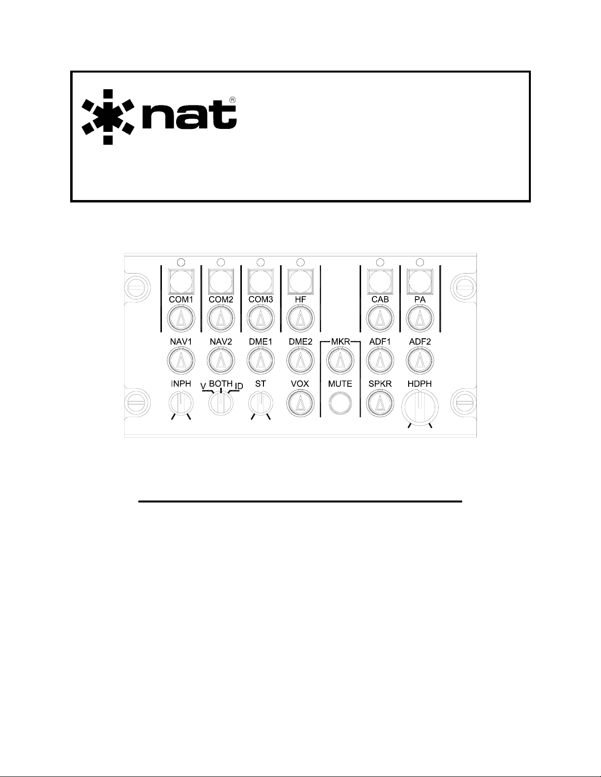
3.3.2 Transmitter Selection
Annunciators
Transmit Buttons
The 3110-100 provides selection controls for four radio transmitters - COM1, COM2,
COM3, and HF (COM4), plus CAB (Cabin interphone - COM6) and PA (Passenger
Address - COM7).
The Transmit buttons are square black push-button switches that are used to select
transceivers for transmission. When a transceiver is selected, the associated
annunciator LED will illuminate green. The transmit buttons are interlocked by internal
logic to prevent simultaneous selection of more than one transmitter.
When a transmit button is selected/deselected, the associated receiver channel is
automatically selected/deselected, even if the receiver control is deselected.
3.3.3 Receiver Selection
Com Receiver
Controls
NavAid Receiver
Controls
The 3110-100 provides volume controls for up to thirteen transceiver and receiver
sources in combination. It supports four COM radios - COM1, COM2, COM3, and HF
(COM4), plus CAB (COM6), PA (COM7), and up to seven navigation (Nav) radios NAV1, NAV2, DME1, DME2, MKR, ADF1, and ADF2.
The Receiver controls are black, illuminated, push-on/push-off rotary knobs that are used to
select transceivers and receivers, and to provide volume control.
When a control is in the OUT position, the corresponding radio is selected (on), and the
arrow on the knob is illuminated. When a control is in the IN position, the corresponding
radio is deselected (off), and the illumination is reduced.
The individual radio volumes can be set by rotating the controls. When the knob is
rotated clockwise (cw) the volume increases, and rotating it counterclockwise (ccw)
decreases the volume.
Page 3-2 Aug 25, 2005
ENG-FORM: 806-0106.DOT
CONFIDENTIAL AND PROPRIETARY TO NORTHERN AIRBORNE TECHNOLOGY LTD.
Page 57

SM3110 Rev. 4.00 3110-100 Audio Control Panel Manual
f
j
3.3.4 INPH (Interphone) Volume Control
The INPH control is a rotary knob that provides cockpit interphone volume
adjustment.
When the knob is rotated cw the volume increases, and rotating it ccw
decreases the volume.
3.3.5 Navigation Filter Selection
The Navigation Filter Selection control is a three-position rotary switch used
to select one of three navigation filter modes - V, BOTH, or ID. The NAV1,
NAV2, ADF1 and ADF2 radios are routed through the filter.
When V is selected, the 1020 Hz notch filter ensures that voice only passes to the 3110100 outputs.
When ID is selected, the 1020 Hz band-pass filter ensures that only the identifier tone
passes to the 3110-100 outputs.
When BOTH is selected, the voice and ID filters are deactivated, and unfiltered audio is
allowed to pass to the 3110-100 outputs
3.3.6 ST (Sidetone) Volume Control
The Sidetone Volume Control is a rotary knob that provides adjustment o
sidetone volume for all transceivers.
When the knob is rotated cw the sidetone volume increases, and rotating it
ccw decreases the volume.
Note: This control does not ad
ust Interphone sidetone volume.
3.3.7 VOX Selection
The VOX control is a black, illuminated, push-on/push-off rotary knob that
is used to select VOX operation, and to adjust the VOX sensitivity.
When the VOX switch is pushed IN, the microphone link to the interphone output is
disabled except when the interphone key is pressed.
When the VOX switch is in the OUT position, the VOX function is enabled and the arrow
on the knob is illuminated. Rotating the control adjusts the VOX sensitivity. If the control
is in the fully ccw position (maximum sensitivity), the unit is in Hot-Mic (VOX minimum)
mode. To decrease the sensitivity, rotate the control cw.
Aug 25, 2005 Page 3-3
ENG-FORM: 806-0106.DOT
CONFIDENTIAL AND PROPRIETARY TO NORTHERN AIRBORNE TECHNOLOGY LTD.
Page 58

3110-100 Audio Control Panel Manual SM3110 Rev. 4.00
r
t
3.3.8 MUTE (Marker Beacon Mute) Selector
The Marker Beacon Mute Selector is a momentary pushbutton control fo
selection of marker beacon muting. When the MUTE button is pushed,
marker receive audio is muted for approximately 30 seconds.
Marker audio can be muted only when the MKR receive audio control is on (see section
3.3.3). If the marker audio is muted, turning the MKR receiver control off and then on
will unmute the marker audio.
3.3.9 SPKR (Speaker) Control
The SPKR control is a black, illuminated, push-on/push-off rotary knob tha
is used to control the speaker audio, and to adjust the speaker volume.
When the SPKR control is in the OUT position, the speaker audio is turned on and the
arrow on the knob is illuminated. Rotating the control adjusts the volume of the speaker
audio, which is a mix of all receiver, interphone (if OXY MIC is selected), and radio
sidetone sources, adjusted for their individual volume and ON/OFF selections.
When the SPKR control is in the IN position, the speaker audio is turned off.
3.3.10 HDPH (Headphone) Control
The HDPH control is a black rotary knob used for adjusting the pilot’s
headphone audio volume.
The control is rotated ccw to reduce the volume, and cw to increase it.
The headphone audio consists of a mix of all receiver, interphone, and sidetone
sources, adjusted for their individual volume selections and ON/OFF selections.
3.3.11 Power Off Emergency Mode
There are two ways in which the 3110-100 can enter Emergency Mode. It will
automatically switch to emergency mode during power-off conditions, or it may be
selected by a separate external switch (See section 3.4.1). The 3110-100 can be linked
to an external indicator to display emergency mode status in either of these conditions.
One transceiver and one aural warning source may be connected for use in emergency
mode. The transceiver is connected to the boom/mask mic audio, radio PTT keyline and
pilot headphones, and the aural warning source is connected to the pilot headphone.
The CVR output contains the pilot headphone audio, which is a sum of the tranceiver's
audio and the aural warning audio.
Without power, the speaker, receiver/transmitter selections, and all other front panel
operations are effectively disabled.
Page 3-4 Aug 25, 2005
ENG-FORM: 806-0106.DOT
CONFIDENTIAL AND PROPRIETARY TO NORTHERN AIRBORNE TECHNOLOGY LTD.
Page 59

SM3110 Rev. 4.00 3110-100 Audio Control Panel Manual
When power is restored to the unit, it will return to the last known transmit select
configuration and annunciator status.
3.3.12 Service Interphones
The 3110-100 has three interfaces for service interphone communications. Each
service interphone interface consists of a service microphone input, a headphone
output, and service keyline for communicating on the service interphone only. They are
not radio transmit capable. All three service headphone interfaces are driven from a
single amplifier.
Transmission
from the pilot boom/mask mic to the Service (CAB) interphone can be enabled
using the CAB interphone transmit select button on the front panel of the 3110 ACP.
3.3.13 Passenger Address
The 3110-100 has a passenger address analog interface which is active whenever PA
is selected for transmit, and the radio PTT or hand mic PTT is keyed. This interface
also provides an output that can mute an externally connected stereo system.
PA audio signals are sent to the PA audio output and to the service headphone outputs.
3.3.14 PTT
When radio or hand mic PTT is activated, the applicable mic audio will be routed to the
selected transmitter, and all receiver and cockpit interphone audio to the pilot’s
headphone and the cockpit speaker will mute, and VOX will be disabled.
Note: PTT activity will not mute aural warnings or sidetone.
3.4 External Control Functions
The design of the 3110-100 allows for connection to various external switches,
annunciators, recorders, and warning generators. If connected, these external components
affect the operation of the 3110-100 as described in the relevant sections below.
3.4.1 Emergency Mode Switch and Annunciator
An external Emergency Mode switch may be connected to the 3110 ACP. The 3110100 can be linked to an external indicator lamp to display emergency mode status.
In emergency mode, one transceiver and one aural warning source may be connected
for use. The transceiver is connected to the boom/mask mic audio, radio PTT keyline
and pilot headphones, and the aural warning source is connected to the pilot
Aug 25, 2005 Page 3-5
ENG-FORM: 806-0106.DOT
CONFIDENTIAL AND PROPRIETARY TO NORTHERN AIRBORNE TECHNOLOGY LTD.
Page 60

3110-100 Audio Control Panel Manual SM3110 Rev. 4.00
headphone. The CVR output contains the pilot headphone audio, which is a sum of the
tranceiver's audio and the aural warning audio.
Without power, the speaker, receiver/transmitter selections, and all other front panel
operations are effectively disabled.
When power is restored to the unit, it will return to the last known transmit select
configuration and annunciator status.
3.4.2 Oxygen Mask Mode
An external switch is used to switch between the Boom Mic and Oxygen Mask Mic
audio sources.
Selecting the Oxygen Mask Mode deactivates any Aural Warning mute that has been
previously activated. Oxygen Mask Mode also enables interphone audio to be heard
over the cockpit speaker.
3.4.3 Cabin Call Tone
A momentary external Cabin Call Tone switch can be connected to the 3110-100 to
indicate to the pilot that the service interphone headset operators wish to communicate
with the cockpit.
Each activation of the switch will cause the Cabin Call Tone to be played once to the
pilot, the service headphone, and to the cockpit speaker outputs.
3.4.4 Speaker Mute (AUX MUTE)
An external momentary switch may be connected to the 3110-100 to mute all audio,
including aural warnings, to the cockpit speaker. (The pilot headphone audio remains
unmuted.)
Audio to the speaker may be restored in four ways: by a second action of the switch; by
selecting and then deselecting Oxygen Mask Mode; by removing and then restoring
power to the unit; or by activating and then deactivating emergency mode (see section
3.4.1).
The 3110-100 can be connected to an external annunciator to indicate that speaker
mute has been activated.
3.4.5 Aural Warning Volume
An external switch may be connected to the 3110-100 to allow selection of high or low
aural warning volume (for all aural warning audio).
Page 3-6 Aug 25, 2005
ENG-FORM: 806-0106.DOT
CONFIDENTIAL AND PROPRIETARY TO NORTHERN AIRBORNE TECHNOLOGY LTD.
Page 61

SM3110 Rev. 4.00 3110-100 Audio Control Panel Manual
3.4.6 Cockpit Voice Recorder (CVR) Audio output
The 3110-100 provides a CVR output carrying the same mix of audio (including
Boom/Mask mic audio input - CVR Hot Mic) as that applied to the headphone output.
3.4.7 Annunciator Test
An external momentary Annunciator test switch may be connected to the 3110-100.
When activated, all transmit annunciator LEDs will illuminate.
3.4.8 Aural Warning Priority
Aural warning inputs are prioritised. The AUX1 and AUX2 inputs have priority over the
AUX3, AUX4 and AUX5 inputs. When a priority input is greater than the priority
switching threshold, the lower priority input is turned off.
End of section 3
Aug 25, 2005 Page 3-7
ENG-FORM: 806-0106.DOT
CONFIDENTIAL AND PROPRIETARY TO NORTHERN AIRBORNE TECHNOLOGY LTD.
 Loading...