

Page 1

RETURN TO THIS MANUAL'S TABLE OF CONTENTS
RETURN TO CD-ROM TABLE OF CONTENTS
Technical
Service
Manual
Part Number: 4114210
Date: 4 May 2004
© 2004 Draeger Medical, Inc.
Rev: T
Narkomed MRI
Narkomed MRI-2
Anesthesia Systems
Page 2

RETURN TO THIS MANUAL'S TABLE OF CONTENTS
RETURN TO CD-ROM TABLE OF CONTENTS
Page 3

RETURN TO THIS MANUAL'S TABLE OF CONTENTS
RETURN TO CD-ROM TABLE OF CONTENTS
Narkomed MRI Service Manual Table of Contents
What's New in Rev. T
DESCRIPTION
SECTION 1: Introduction
1.1 Recommendations. . . . . . . . . . . . . . . . . . . . . . . . . . . . . . . . . . . . . . . . . . . . . . . . . 1-1
1.2 How to use this Manual . . . . . . . . . . . . . . . . . . . . . . . . . . . . . . . . . . . . . . . . . . . . 1-1
1.3 General Troubleshooting Guidelines . . . . . . . . . . . . . . . . . . . . . . . . . . . . . . . . . . 1-1
1.4 General Warnings and Cautions . . . . . . . . . . . . . . . . . . . . . . . . . . . . . . . . . . . . . 1-2
SECTION 2: Diagnostics
2.1 Power-up Diagnostics . . . . . . . . . . . . . . . . . . . . . . . . . . . . . . . . . . . . . . . . . . . . . . 2-1
2.2 Main Service Screen . . . . . . . . . . . . . . . . . . . . . . . . . . . . . . . . . . . . . . . . . . . . . . . 2-3
2.3 Service Log . . . . . . . . . . . . . . . . . . . . . . . . . . . . . . . . . . . . . . . . . . . . . . . . . . . . . . 2-6
2.4 PMS Criteria Screen. . . . . . . . . . . . . . . . . . . . . . . . . . . . . . . . . . . . . . . . . . . . . . . 2-7
2.5 Oxygen Monitor Service Screen . . . . . . . . . . . . . . . . . . . . . . . . . . . . . . . . . . . . . . 2-8
2.6 Pressure Monitor Service Screen. . . . . . . . . . . . . . . . . . . . . . . . . . . . . . . . . . . . . 2-9
SECTION 3: Troubleshooting
3.1 Power Supply and Voltage Distribution . . . . . . . . . . . . . . . . . . . . . . . . . . . . . . . 3-1
3.2 Battery . . . . . . . . . . . . . . . . . . . . . . . . . . . . . . . . . . . . . . . . . . . . . . . . . . . . . . . . . 3-6
3.3 Troubleshooting Guides . . . . . . . . . . . . . . . . . . . . . . . . . . . . . . . . . . . . . . . . . . . 3-6
PAGE
SECTION 4: Replacement Procedures
4.1 Cylinder Yoke Assemblies . . . . . . . . . . . . . . . . . . . . . . . . . . . . . . . . . . . . . . . . . . 4-2
4.2 Cylinder Pressure Regulators . . . . . . . . . . . . . . . . . . . . . . . . . . . . . . . . . . . . . . . 4-5
4.3 Cylinder Cutoff Valves (Canada) . . . . . . . . . . . . . . . . . . . . . . . . . . . . . . . . . . . . . 4-8
4.4 Cylinder and Pipeline Pressure Gauges . . . . . . . . . . . . . . . . . . . . . . . . . . . . . . 4-11
4.5 Flowmeters . . . . . . . . . . . . . . . . . . . . . . . . . . . . . . . . . . . . . . . . . . . . . . . . . . . . . 4-15
4.6 Flow Control Valves . . . . . . . . . . . . . . . . . . . . . . . . . . . . . . . . . . . . . . . . . . . . . 4-19
4.7 Auxiliary O2 Flowmeter . . . . . . . . . . . . . . . . . . . . . . . . . . . . . . . . . . . . . . . . . . 4-22
4.8 Oxygen Supply Failure Protection Device . . . . . . . . . . . . . . . . . . . . . . . . . . . . 4-24
4.9 Alarm Channel and Oxygen Supply Pressure Alarm Switch . . . . . . . . . . . . . 4-27
4.10 Oxygen Ratio Controller . . . . . . . . . . . . . . . . . . . . . . . . . . . . . . . . . . . . . . . . . 4-31
4.11 Vaporizers . . . . . . . . . . . . . . . . . . . . . . . . . . . . . . . . . . . . . . . . . . . . . . . . . . . . . 4-34
4.12 O2 Flush Valve . . . . . . . . . . . . . . . . . . . . . . . . . . . . . . . . . . . . . . . . . . . . . . . . 4-37
4.13 Core-M Monitor . . . . . . . . . . . . . . . . . . . . . . . . . . . . . . . . . . . . . . . . . . . . . . . . 4-40
4.13A VPO Monitor . . . . . . . . . . . . . . . . . . . . . . . . . . . . . . . . . . . . . . . . . . . . . . . . 4-41A
4.14 AV2+ Ventilator Controller (MRI) (Bezel Assembly) . . . . . . . . . . . . . . . . . . 4-42
4.15 Ventilator Solenoid Assembly . . . . . . . . . . . . . . . . . . . . . . . . . . . . . . . . . . . . . 4-45
4.16 Ventilator Bellows Valve & Guide Asm w/Press Lim Ctrl . . . . . . . . . . . . . . 4-47
4.17 Caster . . . . . . . . . . . . . . . . . . . . . . . . . . . . . . . . . . . . . . . . . . . . . . . . . . . . . . . . 4-51
Rev. L
i
Page 4

CONTENTS (continued)
RETURN TO THIS MANUAL'S TABLE OF CONTENTS
RETURN TO CD-ROM TABLE OF CONTENTS
NM MRI
DESCRIPTION
4.18 Battery . . . . . . . . . . . . . . . . . . . . . . . . . . . . . . . . . . . . . . . . . . . . . . . . . . . . . . . 4-53
4.19 Power Supply PCB . . . . . . . . . . . . . . . . . . . . . . . . . . . . . . . . . . . . . . . . . . . . . 4-55
4.20 Primary Power supply (early models) . . . . . . . . . . . . . . . . . . . . . . . . . . . . . . . 4-57
4.20A Primary Power supply (later design) . . . . . . . . . . . . . . . . . . . . . . . . . . . . . 4-58A
4.21 Power Supply Filter . . . . . . . . . . . . . . . . . . . . . . . . . . . . . . . . . . . . . . . . . . . . . 4-59
4.22 Flow Sensor: Machines with VPO Monitor . . . . . . . . . . . . . . . . . . . . . . . . . . . 4-61
SECTION 5: Adjustment And Calibration Procedures
5.1 Cylinder Pressure Regulator Adjustment . . . . . . . . . . . . . . . . . . . . . . . . . . . . . 5-2
5.2 Oxygen Supply Pressure Alarm Switch Adjustment . . . . . . . . . . . . . . . . . . . . . 5-5
5.3 Oxygen Ratio Controller (ORC) Adjustment . . . . . . . . . . . . . . . . . . . . . . . . . . . 5-8
5.4 Oxygen Monitor Calibration: Core-M Monitor . . . . . . . . . . . . . . . . . . . . . . . . . 5-10
5.5 Flow and Pressure Calibration: Core-M Monitor . . . . . . . . . . . . . . . . . . . . . . 5-11
5.6 Oxygen Sensor Calibration: VPO Monitor . . . . . . . . . . . . . . . . . . . . . . . . . . . . 5-12
5.7 Breathing Pressure Monitor Calibration: VPO Monitor . . . . . . . . . . . . . . . . . 5-14
5.8 Vaporizer Interlock Adjustment . . . . . . . . . . . . . . . . . . . . . . . . . . . . . . . . . . . . 5-16
SECTION 6: Periodic Manufacturer’s Service (PMS) Procedure
6.1 Safety Testing . . . . . . . . . . . . . . . . . . . . . . . . . . . . . . . . . . . . . . . . . . . . . . . . . . . 6-3
6.2 Self-Diagnostics: Core-M Monitor . . . . . . . . . . . . . . . . . . . . . . . . . . . . . . . . . . . . 6-4
6.2A Self-Diagnostics: VPO Monitor . . . . . . . . . . . . . . . . . . . . . . . . . . . . . . . . . . . . 6-4A
6.2B Configuration: VPO Monitor . . . . . . . . . . . . . . . . . . . . . . . . . . . . . . . . . . . . . . 6-4A
6.2C Service Data: VPO Monitor . . . . . . . . . . . . . . . . . . . . . . . . . . . . . . . . . . . . . . . 6-4B
6.3 Battery Circuit Test . . . . . . . . . . . . . . . . . . . . . . . . . . . . . . . . . . . . . . . . . . . . . . 6-5
6.4 High Pressure Leak Test . . . . . . . . . . . . . . . . . . . . . . . . . . . . . . . . . . . . . . . . . . . 6-6
6.5 High Pressure Regulator Test . . . . . . . . . . . . . . . . . . . . . . . . . . . . . . . . . . . . . . 6-8
6.6 Gauges . . . . . . . . . . . . . . . . . . . . . . . . . . . . . . . . . . . . . . . . . . . . . . . . . . . . . . . . . 6-9
6.7 Oxygen Supply Failure Protection . . . . . . . . . . . . . . . . . . . . . . . . . . . . . . . . . . 6-10
6.8 Flowmeter Test . . . . . . . . . . . . . . . . . . . . . . . . . . . . . . . . . . . . . . . . . . . . . . . . . 6-11
6.9 Freshgas Leak Test . . . . . . . . . . . . . . . . . . . . . . . . . . . . . . . . . . . . . . . . . . . . . . 6-13
6.10 Absorber System . . . . . . . . . . . . . . . . . . . . . . . . . . . . . . . . . . . . . . . . . . . . . . . 6-14
6.10A Bain Circuit Adapter - if applicable . . . . . . . . . . . . . . . . . . . . . . . . . . . . . . 6-17A
6.10B Vapor Exclusion System . . . . . . . . . . . . . . . . . . . . . . . . . . . . . . . . . . . . . . . 6-17B
6.11 Flow and Pressure Calibration: Core-M Monitor . . . . . . . . . . . . . . . . . . . . . 6-17C
6.11A Flow and Pressure Calibration: VPO Monitor . . . . . . . . . . . . . . . . . . . . . . 6-17D
6.12 Oxygen Cal and Alarm Test: Core-M Monitor . . . . . . . . . . . . . . . . . . . . . . . . 6-18
6.12A O2 MED: VPO Monitor . . . . . . . . . . . . . . . . . . . . . . . . . . . . . . . . . . . . . . . . 6-18A
6.13 Pressure Accuracy Test: Core-M Monitor . . . . . . . . . . . . . . . . . . . . . . . . . . . . 6-19
6.13A Baromed: VPO Monitor . . . . . . . . . . . . . . . . . . . . . . . . . . . . . . . . . . . . . . . . 6-19A
6.14 APNEA and Volume Alarm Test: Core-M Monitor. . . . . . . . . . . . . . . . . . . . . 6-20
6.14A Ultrasonic Flow Sensor: VPO Monitor . . . . . . . . . . . . . . . . . . . . . . . . . . . . 6-21A
6.15 Ventilator Test . . . . . . . . . . . . . . . . . . . . . . . . . . . . . . . . . . . . . . . . . . . . . . . . . 6-22
6.16 Bellows Drive Gas Leak Test . . . . . . . . . . . . . . . . . . . . . . . . . . . . . . . . . . . . . 6-23
6.17 “F” Bellows Test . . . . . . . . . . . . . . . . . . . . . . . . . . . . . . . . . . . . . . . . . . . . . . . . 6-24
6.18 Ventilator Relief Valve Test . . . . . . . . . . . . . . . . . . . . . . . . . . . . . . . . . . . . . . 6-24
6.19 Inspiratory Pressure Limit Test . . . . . . . . . . . . . . . . . . . . . . . . . . . . . . . . . . . 6-25
PAGE
ii
Rev. L
Page 5

RETURN TO THIS MANUAL'S TABLE OF CONTENTS
RETURN TO CD-ROM TABLE OF CONTENTS
NM MRI
CONTENTS (continued)
DESCRIPTION PAGE
6.20 Oxygen Concentration Test . . . . . . . . . . . . . . . . . . . . . . . . . . . . . . . . . . . . . . . 6-25
6.21 Oxygen Ratio Control (ORC) Test . . . . . . . . . . . . . . . . . . . . . . . . . . . . . . . . . 6-27
6.22 Oxygen Flush and 100% O2 Final Test . . . . . . . . . . . . . . . . . . . . . . . . . . . . . 6-28
6.23 Scavenger Interface, A/C . . . . . . . . . . . . . . . . . . . . . . . . . . . . . . . . . . . . . . . . . 6-29
6.24 Open Reservoir Scavenger . . . . . . . . . . . . . . . . . . . . . . . . . . . . . . . . . . . . . . . . 6-30
6.25 Suction Regulator . . . . . . . . . . . . . . . . . . . . . . . . . . . . . . . . . . . . . . . . . . . . . . . 6-32
6.26 Final Check . . . . . . . . . . . . . . . . . . . . . . . . . . . . . . . . . . . . . . . . . . . . . . . . . . . 6-32
SECTION 7: Software Update Procedure
7.1 Software Transfer to PC via Modem . . . . . . . . . . . . . . . . . . . . . . . . . . . . . . . . . . 7-1
7.2 Installing NM MRI Software from a PC . . . . . . . . . . . . . . . . . . . . . . . . . . . . . . . 7-1
SECTION 8: Spare and Replacement Parts
AV-2+ Ventilator Controller (Bezel) Assembly and Remote Solenoid . . . . . . . . . . . . . . 8-2, 8-3
Bellows Valve Assembly, Pressure Limit Control, Bellows Assembly. . . . . . . . . . . . . . 8-4, 8-5
Bellows Valve Assembly details. . . . . . . . . . . . . . . . . . . . . . . . . . . . . . . . . . . . . . . . . . . . 8-6, 8-7
DISS Pipeline Inlets . . . . . . . . . . . . . . . . . . . . . . . . . . . . . . . . . . . . . . . . . . . . . . . . . . . . . 8-8, 8-9
Failsafe Assemblies . . . . . . . . . . . . . . . . . . . . . . . . . . . . . . . . . . . . . . . . . . . . . . . . . . . 8-10, 8-11
ORC Assembly . . . . . . . . . . . . . . . . . . . . . . . . . . . . . . . . . . . . . . . . . . . . . . . . . . . . . . . 8-12, 8-13
Alarm Channel Assembly and related cables . . . . . . . . . . . . . . . . . . . . . . . . . . . . . . . 8-14, 8-15
Flowmeter Shields, Knobs, Labels, Gauges . . . . . . . . . . . . . . . . . . . . . . . . . . . . . . . . 8-16, 8-17
Flow Tubes, Restrictor Assemblies, Flow Control Valve . . . . . . . . . . . . . . . . . . . . . . 8-18, 8-19
Auxiliary O
Cyl. Regulator Assemblies, O
Flowmeter . . . . . . . . . . . . . . . . . . . . . . . . . . . . . . . . . . . . . . . . . . . . . . . . 8-20, 8-21
2
Flush Valve and related parts . . . . . . . . . . . . . . . . . 8-22, 8-23
2
CSA Items: Relief Valve, Cylinder Cutoff Valves . . . . . . . . . . . . . . . . . . . . . . . . . . . . 8-24, 8-25
Yokes, Common Parts, Labels . . . . . . . . . . . . . . . . . . . . . . . . . . . . . . . . . . . . . . . . . . . 8-26, 8-27
Absorber Pole, Casters . . . . . . . . . . . . . . . . . . . . . . . . . . . . . . . . . . . . . . . . . . . . . . . . . 8-28, 8-29
Power Supply/Charger Assembly, Power Cord . . . . . . . . . . . . . . . . . . . . . . . . . . . . . . 8-30, 8-31
Filter Assembly . . . . . . . . . . . . . . . . . . . . . . . . . . . . . . . . . . . . . . . . . . . . . . . . . . . . . . 8-32, 8-33
Battery Box Assembly, machines with Core-M monitor . . . . . . . . . . . . . . . . . . . . . . 8-34, 8-35
Battery Box Assembly, machines with VPO monitor. . . . . . . . . . . . . . . . . . . . . . . . . 8-36, 8-37
Absorber . . . . . . . . . . . . . . . . . . . . . . . . . . . . . . . . . . . . . . . . . . . . . . . . . . . . . . . . . . . . 8-38, 8-39
Man/Auto Selector Valve . . . . . . . . . . . . . . . . . . . . . . . . . . . . . . . . . . . . . . . . . . . . . . . 8-40, 8-41
Open Reservoir Scavenger . . . . . . . . . . . . . . . . . . . . . . . . . . . . . . . . . . . . . . . . . . . . . . 8-42, 8-43
A/C Scavenger. . . . . . . . . . . . . . . . . . . . . . . . . . . . . . . . . . . . . . . . . . . . . . . . . . . . . . . . 8-44, 8-45
Core-M Monitor, Vol & O2 Sensors, Touch-up paint: Euro white, Euro blue . . . . . . 8-46, 8-47
VPO Monitor. . . . . . . . . . . . . . . . . . . . . . . . . . . . . . . . . . . . . . . . . . . . . . . . . . . . . . . . . 8-48, 8-49
Ultrasonic Flow Sensor Assembly and related parts . . . . . . . . . . . . . . . . . . . . . . . . . 8-50, 8-51
Suction Assembly with Re-usable Canister . . . . . . . . . . . . . . . . . . . . . . . . . . . . . . . . 8-52, 8-53
Vaporizer Mounting and Exclusion System parts . . . . . . . . . . . . . . . . . . . . . . . . . . . 8-54, 8-55
Rev. L
iii
Page 6
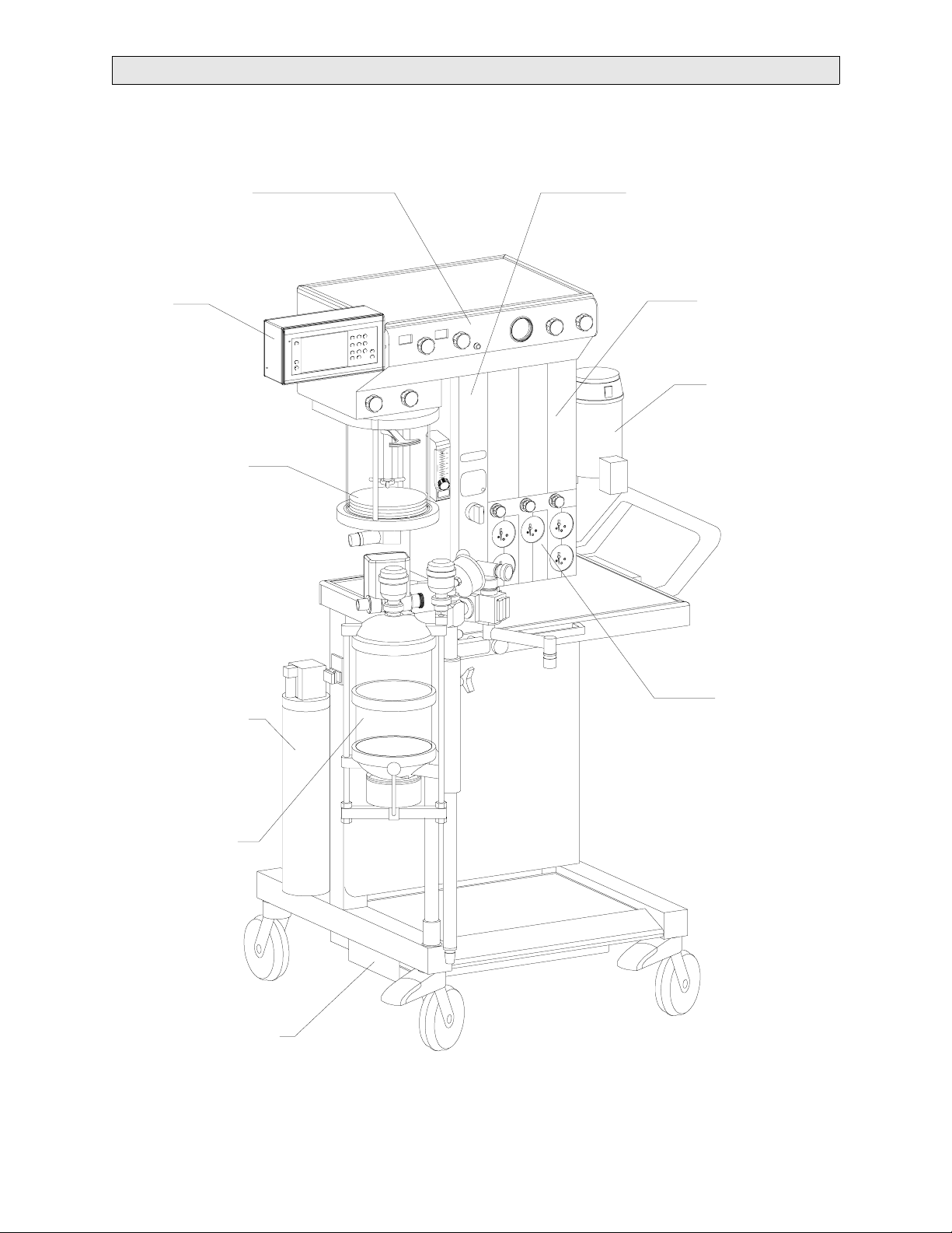
Narkomed MRI Anesthesia System
RETURN TO THIS MANUAL'S TABLE OF CONTENTS
RETURN TO CD-ROM TABLE OF CONTENTS
VENTILATOR
VPO
MONITOR
VENTILATOR
BELLOWS
MAIN SWITCH PANEL
FLOWMETER
BANK
VAPORIZER
SCAVENGER
(OPEN
RESERVOIR)
ABSORBER
POWER SUPPLY
PRESSURE
GAUGES
SV00070
1-0
Rev. E
Page 7

RETURN TO THIS MANUAL'S TABLE OF CONTENTS
RETURN TO CD-ROM TABLE OF CONTENTS
NM MRI
INTRODUCTION
1.0 INTRODUCTION
1.1 Recommendations
Because of the sophisticated nature of Draeger Medical, Inc. anesthesia equipment and its
critical importance in the operating room setting, it is highly recommended that only
appropriately trained and experienced professionals be permitted to service and maintain this
equipment. Please contact DrägerService
Draeger Medical, Inc. also recommends that its anesthesia equipment be serviced at three-
month intervals. Periodic Manufacturer's Service Agreements are available for equipment
manufactured by
Draeger Medical, Inc. For further information concerning these agreements,
please contact us at (800) 543-5047.
Draeger Medical, Inc. products/material in need of factory repair shall be sent to:
1.2 How to use this Manual
®
at (800) 543-5047 for service of this equipment.
DrägerService
3124 Commerce Drive
Telford, PA 18969 U.S.A.
(Include RMA Number)
The manual is divided into several sections. The DIAGNOSTICS section describes self-test and
service diagnostics for checking the system functions. An understanding of the on-board service
capabilities is necessary before any attempt is made to troubleshoot the unit. The
TROUBLESHOOTING section provides troubleshooting guides to assist the Technical Service
Representative (TSR) in locating the source of a problem. The REPLACEMENT PROCEDURES
section contains instructions for removal and replacement of the assemblies that are considered
field-replaceable. The ADJUSTMENT AND CALIBRATION PROCEDURES section contains the
field procedures needed to restore original system specifications. The Periodic Manufacturer's
Service (PMS) PROCEDURE section outlines the steps required to verify the electrical,
mechanical and pneumatic safety of the unit and also identifies components requiring periodic
replacement.
1.3 General Troubleshooting Guidelines
Troubleshooting the Narkomed MRI should always begin by communicating with those who
observed or experienced a problem with the unit. This may eliminate unnecessary
troubleshooting steps. Once a general problem is identified, refer to the troubleshooting flow
charts in Section 3 to determine the proper corrective action to be taken.
After a component has been replaced, verify that the unit is operating properly by running the
appropriate diagnostic procedure. The PMS PROCEDURE in Section 6 must also be performed
after any component has been replaced.
The general arrangement of the Narkomed MRI Anesthesia System is shown on the opposite
page.
WAR NING S are used in this manual before procedures which if not performed correctly could
result in personal injury.
CAUTIONS are used in this manual to alert service personnel to the possibility of damage to the
equipment if a procedure is not performed correctly.
1-1
Page 8

RETURN TO THIS MANUAL'S TABLE OF CONTENTS
RETURN TO CD-ROM TABLE OF CONTENTS
INTRODUCTION (continued)
NM MRI
1.4 General Warnings and Cautions
The following list of warnings and cautions apply to general operation and maintenance of the
Narkomed MRI. Warnings and cautions about installing and operating specific parts appear
with those topics.
WARNING: The user of this anesthesia machine must comply with warnings, cautions,
and checkout procedures printed on the machine or on the pullout panel.
Failure to do so may result in injury to the patient, operator, others, or
equipment.
WARNING: Any person involved with the setup, operation, or maintenance of the
Narkomed MRI anesthesia system must be thoroughly familiar with this
instruction manual.
WARNING: Do not place any object on this machine unless it is specifically labeled to be
used in an MRI scanning room and on the Narkomed MRI anesthesia system.
Objects placed on this machine that are not designed for use with this
anesthesia system may be strongly attracted to the magnet and may cause
serious injury or death when the machine is used in an MRI scanning room.
WARNING: Always lock the casters after this anesthesia machine has been positioned in
the MRI scanner room. Magnetic attractive forces between the magnet and
the anesthesia machine may cause unintentional movement of the anesthesia
machine if the casters are unlocked.
WARNING: The power supply charger assembly must not be taken into the magnet room.
Damage to the equipment, MRI system, or personal injury could result.
WARNING: The Narkomed MRI has been tested only with magnets having field strengths
of up to 1.5 tesla. Moving the machine near higher strength magnets (greater
than 1.5 tesla) could result in machine malfunction or unmanageable
attractive forces that could lead to serioius injury or death.
WARNING: The Narkomed MRI-2 has been tested with magnets having field strengths of
up to 3.0 tesla. Moving the machine near higher strength magnets (greater
than 3.0 tesla) could result in machine malfunction or unmanageable
attractive forces that could lead to serious injury or death.
WARNING: This anesthesia system will not respond automatically to certain changes in
patient condition, operator error, or failure of components. The system is
designed to be operated under the constant surveillance and control of a
qualified operator.
WARNING: Use only nonmagnetic (aluminum) E-cylinders with this machine. Steel
cylinders can cause serious injury or death if brought into an MRI scanning
room.
1-2
Rev. F
Page 9

RETURN TO THIS MANUAL'S TABLE OF CONTENTS
RETURN TO CD-ROM TABLE OF CONTENTS
NM MRI
INTRODUCTION (continued)
WARNING: No third-party components shall be attached to the anesthesia machine,
ventilator, or breathing system (except for certain approved exceptions).
Contact
DrägerService
®
for further information. DrägerService
®
is a division of
Draeger Medical, Inc.
WARNING: Not for use with flammable anesthetics. To avoid explosion hazards, do not
use flammable anesthetic agents such as diethyl-ether and cyclopropane with
this machine. Only anesthetic agents which comply with the requirements for
non-flammable anesthetic agents per IEC standard or national equivalent
shall be used with this anesthesia machine.
CAUTION: When moving the machine, be sure to set the absorber to its lowest position on
the absorber pole. To avoid personal injury or damage to the unit, do not use
the absorber pole to push or pull the machine. It is recommended that two
people move the machine to aid in maneuverability on inclines, around
corners, and over raised thresholds.
CAUTION: The Narkomed MRI is designed for MRI use only as a system. The user should
not assume that individual components of the system can be safely used with
MRI scanners.
CAUTION: Although the Narkomed MRI is designed to minimize the effects of ambient
radio-frequency interference, machine functions may be adversely affected by
the operation of electrosurgical equipment or short-wave or microwave
diathermy equipment in the vicinity.
The following messages appear in French on the Narkomed MRI:
ATTENTION: Lors du déplacement de l'appareil, veiller à placer l'absorbeur le plus bas
possible sur le montant. Pour éviter tout risque de blessure corporelle ou
endommagement de l'appareil, ne pas pousser ou tirer sur le montant de
l'absorbeur pour déplacer l'appareil. Il est recommandé que deux personnes
déplacent l'appareil sur des plans inclinés, dans des angles et pour passer
des seuils surélevés.
AVERTISSEMENT: L'utilisateur de l'appareil d'anesthésie doit se conformer aux
avertissements, mises en garde et procédures de vérification
imprimés sur l'appareil ou sur le panneau rétractable. Négliger de
faire cela risque de provoquer des blessure chez le patient, l'opérateur
ou d'autres personnes et risque également d'endommagement
l'appareil.
AVERTISSEMENT: Toute personne chargée de la préparation, de l'utilisation ou de
l'entretien de l'appareil d'anesthésie Narkomed MRI doit très bien
connaître le contenu de ce manuel d'utilisation.
1-3
Page 10

RETURN TO THIS MANUAL'S TABLE OF CONTENTS
RETURN TO CD-ROM TABLE OF CONTENTS
INTRODUCTION (continued)
NM MRI
AVERTISSEMENT: Ne placer aucun objet sur cet appareil à moins qu'il n'ait été
spécifiquement approuvé pour l'utilisation dans une salle IRM avec
un appareil d'anesthésie Narkomed MRI. Tout objet non conforme
déposé sur cet appareil pourrait être fortement attiré par l'aimant et
pourrait occasionner des blessures graves ou fatales lorsque l'appareil
d'anesthésie est utilisé dans la salle IRM.
AVERTISSEMENT: Toujours bloquer les roues après avoir placé cet appareil d'anesthésie
à l'endroit voulu dans la salle IRM. Les forces d'attraction magnétique
entre l'aimant et l'appareil d'anesthésie peuvent provoquer un
déplacement imprévu de ce dernier si les roues ne sont pas bloquées.
AVERTISSEMENT: Ne pas amener le chargeur de batterie dans la salle IRM car cela
présenterait un risque d'endommagement du matériel et du système
IRM, ou de blessure corporelle.
AVERTISSEMENT: Cet appareil d'anesthésie Narkomed MRI a été vérifiée avec des
aimants possédant des champs magnétiques jusqu’á 1,5 tesla. Installé
l’appareil prés d’un aimant plus puissant (plus de 1,5 tesla) pourrait
amener l’appareil á mal monctionner ou produire des forces
d’attractions incontrôlables qui pourait causer des blessures sérieuses
ou la mort.
AVERTISSEMENT: Cet appareil d'anesthésie Narkomed MRI-2 a été vérifiée avec des
aimants possédant des champs magnétiques jusqu’á 3,0 tesla. Installé
l’appareil prés d’un aimant plus puissant (plus de 3,0 tesla) pourrait
amener l’appareil á mal monctionner ou produire des forces
d’attractions incontrôlables qui pourait causer des blessures sérieuses
ou la mort.
AVERTISSEMENT: Ce système d'anesthésie ne réagit pas automatiquement à certains
changements de l'état physiologique du patient, aux erreurs de
l'opérateur ou aux défaillances des composants. Il a été conçu de
manière à être utilisé sous le contrôle permanent de l'opérateur.
AVERTISSEMENT: Utiliser uniquement des bouteilles de type E non magnétiques (en
aluminium) avec cet appareil. L'utilisation de bouteilles en acier dans
la salle IRM pourrait occasionner des blessures graves ou mortelles.
AVERTISSEMENT: Ne pas utiliser de composants en provenance d'autres fabricants avec
l'appareil d'anesthésie, le ventilateur ou le circuit d'anesthésie, à
moins qu'ils n'aient été approuvés au préalable. Contacter le service
technique de Draeger Medical, Inc. pour des informations
complémentaires.
Rev. A
1-4
Page 11

RETURN TO THIS MANUAL'S TABLE OF CONTENTS
RETURN TO CD-ROM TABLE OF CONTENTS
NM MRI
INTRODUCTION (continued)
AVERTISSEMENT: Ne pas utiliser l'appareil d'anesthésie avec des anesthésiques
inflammables. Pour éviter tout risque d'explosion, ne pas utiliser
d'anesthésiques inflammables tels que l'éther et le cyclopropane.
Seuls les anesthésiques conformes aux exigences relatives aux
anesthésiques ininflammables de la norme CEI ou toute norme
nationale équivalente pourront être utilisés avec cet appareil.
AVERTISSEMENT: Lors du déplacement de l'appareil d'anesthésie, enlever tous les
moniteurs et autre matériel de l'étagère supérieure, retirer
l'absorbeur et n'utiliser que les poignées ou les barres de poussée/
traction. L'appareil d'anesthésie ne doit être déplacé que par des
personnes suffisamment fortes pour en supporter le poids. Draeger
Medical, Inc. recommande que deux personnes déplacent l'appareil
d'anesthésie afin de le manouvrer plus facilement. Veiller à ce que
l'appareil ne bascule pas lors du déplacement sur des plans inclinés,
dans des angles et au passage de seuils (portes et ascenseurs, par
exemple). Ne pas faire passer l'appareil sur des tuyaux, des fils
électriques ou d'autres obstacles se trouvant sur le sol.
ATTENTION: L'appareil d'anesthésie Narkomed MRI doit être utilisé uniquement en tant
que système pour l'imagerie à résonance magnétique. L'utilisateur ne doit
pas présumer que chaque composant du système peut être utilisé seul pour
l'IRM sans présenter de risques.
ATTENTION: Bien que l'appareil d'anesthésie Narkomed MRI soit conçu de manière à
minimiser le parasitage électromagnétique, son fonctionnement peut être
affecté par l'utilisation de générateurs d'électrochirurgie ou d'appareils de
diathermie à ondes courtes ou d'appareils à micro-ondes se trouvant aux
alentours.
ATTENTION: Ne pas placer plus de 23 kg (50 livres) sur l'appareil.
. . . . . . . . . . . . . . . . . . . . . . . . . . . . . . . . . . . . . . . . . . . . . . . . . . . . . . . . . . . . . . . . . . . . . . . . . . . . . . . . . . .
1-5
Page 12

RETURN TO THIS MANUAL'S TABLE OF CONTENTS
RETURN TO CD-ROM TABLE OF CONTENTS
INTRODUCTION (continued)
Copyright
Copyright © 2004 by Draeger Medical, Inc. All rights reserved. No part of this publication may
be reproduced, transmitted, transcribed, or stored in a retrieval system in any form or by any
means, electronic or mechanical, including photocopying and recording, without the written
permission of Draeger Medical, Inc.
Trademark Notices
NM MRI
Datagrip, DrägerService, Narkomed, Narkomed GS, O.R. Data Manager, ORM, Quality Service
For Life, Respitone,
trademarks of
respective owners.
Disclaimer
The content of this manual is furnished for informational use only and is subject to change
without notice. Draeger Medical, Inc. assumes no responsibility or liability for any errors or
inaccuracies that may appear in this manual.
Draeger Medical, Inc. All other products or name brands are trademarks of their
Vigilance Audit, Vitalert, Vitalink, and Fabius GS are registered
1-6
Page 13

RETURN TO THIS MANUAL'S TABLE OF CONTENTS
RETURN TO CD-ROM TABLE OF CONTENTS
NM MRI
DIAGNOSTICS
2.0 DIAGNOSTICS
The Narkomed MRI anesthesia system includes a volume, pressure, and oxygen monitor.
If your system is equipped with an Omicron (Core-M) monitor, refer to the
Monitor Instructions for Operation
(Part No. 4114448) for power-up diagnostic indications,
NAD Omicron
calibration, and setting of alarm parameters. Power to the monitor is supplied by the
Narkomed MRI anesthesia system. A description of the power distribution scheme along
with a troubleshooting guide is given in the next section.
The descriptions that follow apply to systems equipped with a VPO monitor.
2.1 Power-up Diagnostics
The VPO monitor contains a diagnostic system that monitors certain system functions
and records their operational status. Following a brief System Startup display at
power up, the diagnostics screen shown in Figure 2-1 appears. This display includes
one of three messages at the completion of the diagnostics:
FUNCTIONAL: This message indicates that the Narkomed MRI has passed all
power-up tests and is fully functional. The machine will proceed to
the MACHINE MONITOR screen after a short delay.
CONDITIONALLY This message indicates that a minor problem has been
FUNCTIONAL: detected. The Narkomed MRI will retain this display until any key is
pressed, then the MACHINE MONITOR screen will be displayed.
NON-FUNCTIONAL: This message indicates that a serious problem has been detected. The
machine will not proceed into the MACHINE MONITOR or SYSTEM
MONITOR screen.
The PREVENTIVE MAINTENANCE DUE message will appear on the screen if the
current date exceeds the Periodic Manufacturer's Service due date stored in the
machine.
Further diagnostic functions are available through service screens that can be called
up at the display panel. The following paragraphs provide a description of each service
screen that can be accessed at the display. If no display is present upon system powerup, refer to Section 3 of this manual for troubleshooting assistance.
Rev. E
2-1
Page 14

DIAGNOSTICS (continued)
NARKOMED MRI
COPYRIGHT 2000 DRAEGER MEDICAL, INC.
VERSION: 1.00 NM MRI
SOFTWARE ID: 3B31
DIAGNOSTIC TESTS
FIRMWARE PASS
RAM PASS
VIDEO PASS
A/D CONVERTER PASS
AUDIO PASS
CLOCK PASS
NON-VOLATILE MEMORY PASS
PERIODIC CERTIFICATION DUE
FUNCTIONAL
RETURN TO THIS MANUAL'S TABLE OF CONTENTS
RETURN TO CD-ROM TABLE OF CONTENTS
NM MRI
Figure 2-1. Power-up Diagnostics Screen
2-2
Rev. E
Page 15

NM MRI
2.2 Main Service Screen
2.2.1 View Mode
The Main Service Screen displays the machine serial number, the last
service date, hours run since last service and total hours run.
RETURN TO THIS MANUAL'S TABLE OF CONTENTS
RETURN TO CD-ROM TABLE OF CONTENTS
DIAGNOSTICS (continued)
SRVC
LOG
PMS
SCHED
To access the Main Service Screen, press and hold the Oxygen
and Volume
screen shown in Figure 2-2 will then appear.
Press the
paragaph), or press the key next to
screen.
MAIN SERVICE SCREEN
MACHINE SERIAL NUMBER : XXXXXXXX
LAST SERVICE DATE : 2-29-2000
HOURS RUN SINCE LAST SERVICE: 263
TOTAL HOURS RUN : 624
Low Limit keys, and press the key. The View Mode service
key to proceed to the Service Mode (described in the next
5
EXIT to return to the monitoring
5
High Limit
Rev. E
MON
CAL
PORT
SERVICE CODE
Figure 2-2. Main Service Screen, View Mode
VIEW
2-3
SELECT
EXIT
Page 16

DIAGNOSTICS (continued)
2.2.2 Service Mode
In this screen, the Service Code Changes to SRVC.
Press the key next to SELECT to enable the Technical Service ID entry
as described on the next page.
RETURN TO THIS MANUAL'S TABLE OF CONTENTS
RETURN TO CD-ROM TABLE OF CONTENTS
NM MRI
SRVC
LOG
PMS
SCHED
MON
CAL
PORT
Figure 2-3. Main Service Screen, Service Mode
MAIN SERVICE SCREEN
MACHINE SERIAL NUMBER : XXXXXXXX
LAST SERVICE DATE : 2-29-2000
HOURS RUN SINCE LAST SERVICE: 263
TOTAL HOURS RUN : 624
SERVICE CODE
SRVC
SELECT
EXIT
2-4
Rev. E
Page 17

NM MRI
2.2.3 Service Mode: I.D. Entry
The Service Mode screen appears as shown in Figure 2-4. Press the key
next to
and keys to display the desired character. Press the key next to
SELECT to advance to the next digit, and enter the next and remaining
I.D. characters in the same manner.
When this screen is entered, an entry is made in the Service Log.
To access any of the other service screens described on the following
pages, press the key next to the desired function on the left side of the
screen: Service Log, PMS Schedule, Monitor Calibration, or Port
communication settings.
SELECT. Enter the first digit of your service code by using the
6
RETURN TO THIS MANUAL'S TABLE OF CONTENTS
RETURN TO CD-ROM TABLE OF CONTENTS
DIAGNOSTICS (continued)
5
RESET
SRVC
LOG
PMS
SCHED
MON
CAL
PORT
Pressing the key next to
LAST SERVICE to zero, and the LAST SERVICE DATE to the current
date.
If desired, press the key next to
MAIN SERVICE SCREEN
MACHINE SERIAL NUMBER : XXXXXXXX
LAST SERVICE DATE : 2-29-2000
HOURS RUN SINCE LAST SERVICE: 263
TOTAL HOURS RUN : 624
TECHNICAL SERVICE
REPRESENTATIVE I.D.
0 0 0
RESET will reset the HOURS RUN SINCE
EXIT to return to the monitoring screen.
SELECT
0
EXIT
Rev. E
Figure 2-4. Main Service Screen, Service Mode
2-5
Page 18

DIAGNOSTICS (continued)
2.3 Service Log
From the Service Screen (described earlier), press the key next to SRVC LOG.
Figure 2-5 shows an example of the screen that will appear. This screen allows
you to view the events recorded in the machine's service log. Use the and
keys to scroll down or up through the log entries.
RETURN TO THIS MANUAL'S TABLE OF CONTENTS
RETURN TO CD-ROM TABLE OF CONTENTS
NM MRI
6
5
Press the key next to
EXIT to return to the Main Service Screen.
SERVICE LOG
DATE TIME PARAMETER CODE
02-11-00 10:26 00000000 0000
SYSTEM POWERUP
02-11-00 10:30 00000000 E400
AUDIOGEN SPKR CHK
02-13-00 07:30 00000004 E100
Figure 2-5. Service Log
2-6
EXIT
Rev. E
Page 19

NM MRI
2.4 PMS Criteria Screen
The PMS Criteria Screen allows you to select the month when the
PREVENTIVE MAINTENANCE DUE message appears on the power-up
diagnostics screen.
RETURN TO THIS MANUAL'S TABLE OF CONTENTS
RETURN TO CD-ROM TABLE OF CONTENTS
DIAGNOSTICS (continued)
From the Service Screen (described earlier), press the hidden key next to
SCHED
Figure 2-6 shows an example of the screen that will appear. Use the and
keys to set the desired month.
Press the key next to
SELECT CRITERIA FOR
“PREVENTIVE MAINTENANCE” MESSAGE
.
EXIT to return to the Main Service Screen.
PMS
5
6
Rev. E
MONTH
SEP
2000
Figure 2-6. PMS Criteria Screen
EXIT
2-7
Page 20

DIAGNOSTICS (continued)
2.5 Oxygen Monitor Service Screen
The Oxygen Monitor Service Screen shown in Figure 2-7 displays current
readings for the O
values.
cells, a zero calibration procedure, and the stored calibration
2
RETURN TO THIS MANUAL'S TABLE OF CONTENTS
RETURN TO CD-ROM TABLE OF CONTENTS
NM MRI
From the Service Screen (described earlier), press the key next to
To perform a zero calibration, follow the calibration procedure shown on the
screen. Pressing the key next to
calibration.
To proceed to the Pressure Monitor Service Screen, press the key next to
. To return to the Main Service Screen, press the key next to EXIT.
MON
ZERO stores the current values as the new zero
MON CAL.
OXYGEN MONITOR SERVICE SCREEN
CURRENT CELL A: 238
CURRENT CELL B: 250
ZERO
PRES
ZERO CALIBRATION PROCEDURE:
- REMOVE O2 CELL FROM HOUSING
- LET CURRENT CELL VALUES STABILIZE
- PRESS “ZERO” KEY TO ENTER
CALIBRATION VALUES
- REINSTALL O2 CELL IN SENSOR HOUSING
STORED ZERO CELL A: 250
STORED ZERO CELL B: 250
Figure 2-7. Oxygen Monitor Service Screen
2-8
PRES
MON
EXIT
Rev. E
Page 21

NM MRI
2.6 Pressure Monitor Service Screen
The Pressure Monitor Service Screen shown in Figure 2-8 displays the current
reading for airway pressure, a procedure for zero and span calibration, and the
stored calibration values.
To enter the Pressure Monitor Service Screen from the Oxygen Monitor Service
Screen (described earlier), press the key next to
To perform a zero calibration, follow the procedure shown on the screen.
Pressing the key next to
calibration.
To perform a span calibration, follow the procedure shown on the screen.
Pressing the key next to
calibration.
RETURN TO THIS MANUAL'S TABLE OF CONTENTS
RETURN TO CD-ROM TABLE OF CONTENTS
DIAGNOSTICS (continued)
PRES MON (ref. Figure 2-6).
ZERO stores the current value as the new zero
SPAN stores the current value as the new span
To return to the Oxygen Monitor Service Screen, press the key next to
. To return to the Main Service Screen, press the key next to EXIT.
MON
PRESSURE MONITOR SERVICE SCREEN
CURRENT PRESSURE VALUE: 250
ZERO CALIBRATION PROCEDURE:
- REMOVE PRESSURE SAMPLE LINE FROM
ABSORBER, EXPOSE TO AIR.
- LET CURRENT PRESSURE VALUE STABILIZE
- SELECT “ZERO” KEY TO
ENTER CALIBRATION VALUES.
SPAN CALIBRATION PROCEDURE:
- REMOVE PRESSURE SAMPLE LINE FROM
ABSORBER, APPLY 50 CMH2O CONSTANT
PRESSURE AT THE SAMPLE LINE, VERIFIED
BY A KNOWN, CALIBRATED METER.
- LET PRESSURE VALUE STABILIZE
- SELECT THE “SPAN” KEY TO
ENTER THE CURRENT VALUE.
ZERO
SPAN
OXY
MON
EXIT
OXY
Rev. E
Figure 2-8. Pressure Monitor Service Screen
2-9
Page 22

DIAGNOSTICS (continued)
2.7 Deleted
RETURN TO THIS MANUAL'S TABLE OF CONTENTS
RETURN TO CD-ROM TABLE OF CONTENTS
NM MRI
2-10
Rev. L
Page 23

NM MRI
3.0 TROUBLESHOOTING
RETURN TO THIS MANUAL'S TABLE OF CONTENTS
RETURN TO CD-ROM TABLE OF CONTENTS
TROUBLESHOOTING GUIDE
This section contains information to assist the DrägerService
®
qualified Technical
Service Representative (TSR) in locating electrical faults affecting the Narkomed MRI
anesthesia system. Since most troubleshooting efforts begin with verifying power
supply voltages, the following paragraph outlines the voltage distribution scheme
within the machine along with test points for each of the voltages.
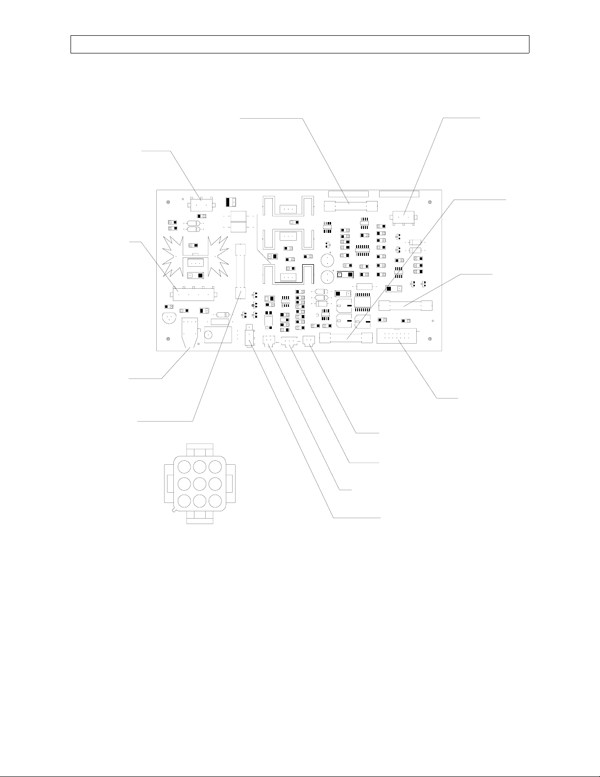
3.1 Power Supply and Voltage Distribution
Power is distributed from the battery box PCB assembly to the alarm channel,
monitor, and flow sensor electronics module on machines with a VPO monitor.
Power for the ventilator controller is obtained from the alarm channel. Table 3-1
lists the test points and acceptable ranges for each voltage; Figures 3-1 and 3-2
show test point locations. Simplified electrical block diagrams are shown in
Figures 3-3 and 3-4.
TABLE 3-1: TEST POINTS AND ALLOWABLE RANGES
BATTERY BOX PCB
VOLTAGE ACCEPTABLE RANGE
(Machines with Core-M monitor)
J1-1 + 13.8 VDC input* 13.6 to 14.0 VDC
J4-1 + 9 VDC to monitor 8.45 to 9.55 VDC
J3-1 + 8 VDC to alarm channel 7.55 to 8.45 VDC
J1-2, J4-2, J3-14 Common
BATTERY BOX PCB
VOLTAGE ACCEPTABLE RANGE
(Machines with VPO monitor)
J7-1 + 8 VDC to monitor 7.72 to 8.36 VDC
J4-1 + 12 VDC to Gill flow sensor 11.61 to 12.54 VDC
J7-2, J4-2 Common
ALARM CHANNEL VOLTAGE ACCEPTABLE RANGE
J3-9 (Wht) + 8 VDC to vent controller 7.55 to 8.45 VDC
J3-3 (Orn) Common
* Applies to early models, measured with battery fully charged and System Power switch at
STANDBY.
On later models with Jerome power supply including machines with VPO monitor, input
voltage is measured at DC power cable Pins 1& 2, with cable unplugged. Range: 13.6 to 14.5
VDC.
Rev. L
3-1
Page 24

TROUBLESHOOTING GUIDE (continued)
RETURN TO THIS MANUAL'S TABLE OF CONTENTS
RETURN TO CD-ROM TABLE OF CONTENTS
NM MRI
J1 FROM
BATTERY
CHARGER
J2 FROM
BATTERY
FI BATTERY
FUSE
(TYPE 3AG,
FAST, 10A,
250V,
312 010)
F3 8V SUPPLY FUSE
(TYPE 3AG, SLO-BLO,
1A, 250V, 313 001)
SV00034
J3 TO
ALARM
CHANNEL
J4 TO
CORE-M
MONITOR
CONNECTION FOR
FIBER OPTIC CABLE
ALARM
CHANNEL
CONNECTOR J3
(TYPE 3AG, FAST, 0.75A, 250V, 312.750)
987
654
321
F2 9V SUPPLY FUSE
FIGURE 3-1. Power Supply Voltage Test Points: Machines with Core-M Monitor
3-2
Rev. E
Page 25
RETURN TO THIS MANUAL'S TABLE OF CONTENTS
RETURN TO CD-ROM TABLE OF CONTENTS
NM MRI
F1 BATTERY FUSE, 10A, 3AG FAST J2 FROM
J1 POWER IN
J7 TO NAD
MONITOR
TROUBLESHOOTING GUIDE (continued)
BATTERY
F4
FLOW SENSOR
POWER FUSE
0.5A, 3AG, FAST
F2 8V
SUPPLY FUSE
1A, 3AG,
SLO-BLO
RX1 FIBER
OPTIC CABLE FROM
VENT CONTROLLER
F3 MONITOR
POWER FUSE
3A, 3AG, FAST
ALARM
CHANNEL
CONNECTOR J3
987
654
321
J4 FLOW SENSOR MODULE J1
J5 FLOW SENSOR MODULE J2
J8 HIGH FIELD SIGNAL TO MONITOR
J6 TO VENTILATOR SOLENOID
FIGURE 3-2. Power Supply Voltage Test Points: Machines with VPO Monitor
SV00181
J3 TO ALARM
CHANNEL
Rev. E
3-3
Page 26

TROUBLESHOOTING GUIDE (continued)
FLOWMETER
RETURN TO THIS MANUAL'S TABLE OF CONTENTS
RETURN TO CD-ROM TABLE OF CONTENTS
NM MRI
LIGHTS
FEED
THRU
J2
FILTERS
9V POWER
FOR
MONITOR
J4
BATTERY
BOX PCB
ALARM
CHANNEL
J4
J3
J1
J6
J3
30 PSI
SW
RX1
J2
BATTERY
VENTILATOR
CONTROLLER
FIBER OPTIC
INTERFACE
TX1
VENT
SOLENOID
J1
FIBER
OPTIC
CABLE
FILTER
BOX
MAINS
POWER
SUPPLY
FIGURE 3-3. Narkomed MRI Block Diagram: Machines w/Core-M Monitor
3-4
Rev. E
Page 27

NM MRI
RETURN TO THIS MANUAL'S TABLE OF CONTENTS
RETURN TO CD-ROM TABLE OF CONTENTS
TROUBLESHOOTING GUIDE (continued)
FLOWMETER
LIGHTS
FEED
THRU
J2
FILTERS
NAD MONITOR
FLOW
SENSOR
MODULE
J1
J4
J7
BATTERY
BOX PCB
J1
ALARM
CHANNEL
J8
J3
J4
J3
30 PSI
SW
RX1
J2
BATTERY
VENTILATOR
CONTROLLER
FIBER OPTIC
INTERFACE
TX1
VENT
SOLENOID
J1
FIBER
OPTIC
CABLE
J6
FILTER
BOX
MAINS
J1
POWER
SUPPLY
FIGURE 3-4. Narkomed MRI Block Diagram: Machines w/VPO Monitor
Rev. F
3-5
Page 28

TROUBLESHOOTING GUIDE (continued)
3.2 Battery
With the System Power switch at STANDBY and the power supply/charger box
disconnected, the battery voltage at full charge should be within the range of 12.5
to 13.2 VDC. Battery voltage can be measured at J2 on the battery box PCB.
During battery operation, the low battery cutoff voltage should be within the
range of 10.7 to 11.3 VDC.
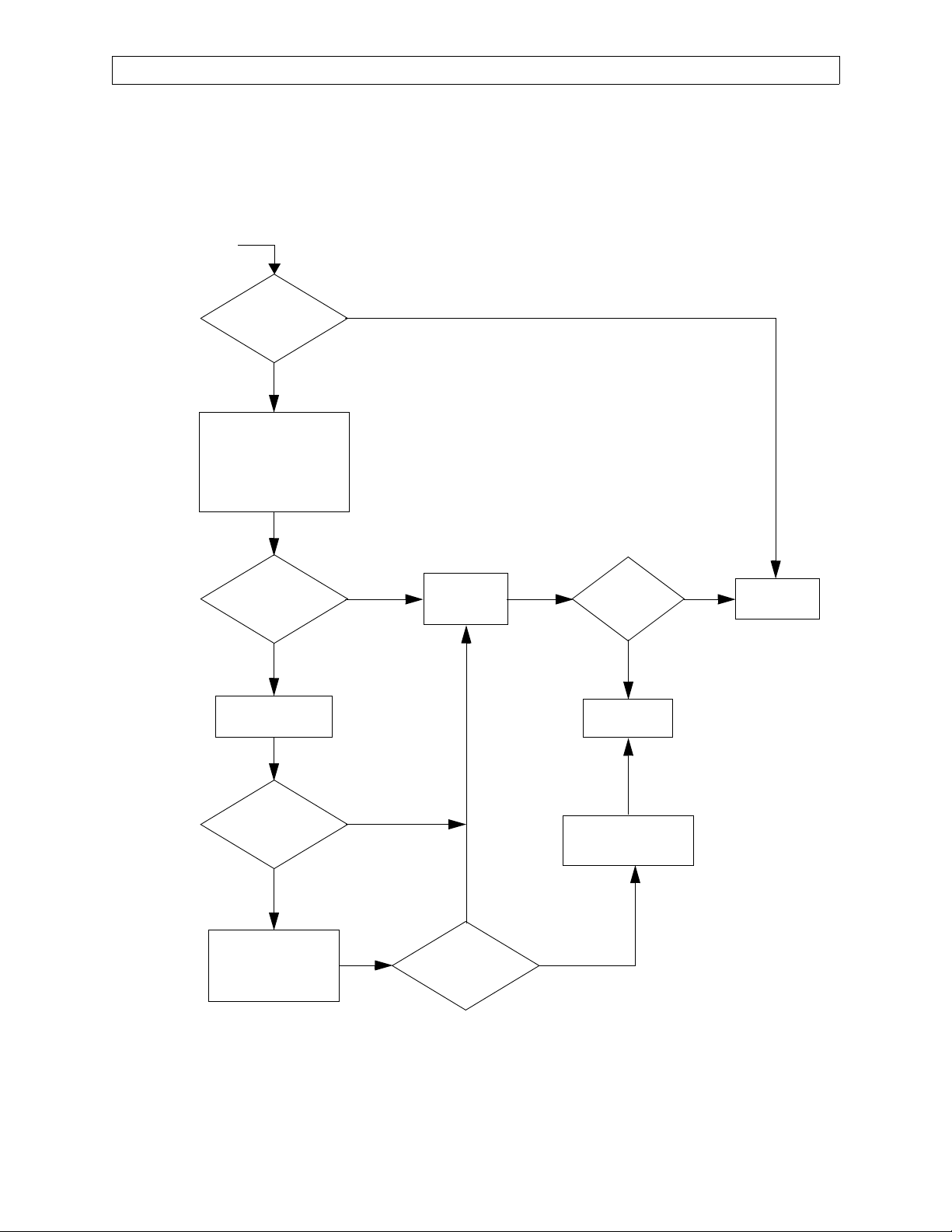
3.3 Troubleshooting Guides
Table 3-2 lists common failure modes and symptoms (excluding simultaneous
multiple faults) for the Narkomed MRI. Each failure mode or symptom is keyed to
a troubleshooting guide flow chart at the back of this section to assist the TSR in
locating a problem. These flow charts assume that the machine is plugged into an
AC outlet with the correct voltage, and the machine is not running on its backup
battery.
RETURN TO THIS MANUAL'S TABLE OF CONTENTS
RETURN TO CD-ROM TABLE OF CONTENTS
NM MRI
TABLE 3-2: NARKOMED MRI FAILURE MODE AND SYMPTOM LIST
FAILURE MODE / SYMPTOM CORRECTIVE ACTION
Monitor Inoperative (Core-M Monitor) Guide 1
No O
Supply Pressure Alarm Guide 2
2
Ventilator Inoperative Guide 3
No Audio Alarms, Display Blank,
Guide 4
Keypad Inoperative (VPO Monitor)
Serial Port Communication Failure
Guide 5
(VPO Monitor)
Loss of Breathing Pressure Monitor
Guide 6
(VPO Monitor)
Loss of Respiratory Volume Monitor
Guide 7
(VPO Monitor)
3-6
Rev. E
Page 29

RETURN TO THIS MANUAL'S TABLE OF CONTENTS
NM MRI
GUIDE 1: Monitor Inoperative (Core-M Monitor)
START
RETURN TO CD-ROM TABLE OF CONTENTS
TROUBLESHOOTING GUIDE (continued)
CONNECT
POWER CORD
N
Y
ARE
ALL MONITOR
FUNCTIONS
WORKING?
N
IS
POWER CORD
CONNECTED?
Y
IS POWER
AVAILABLE AT
CONNECTOR?
Y
ARE
ALL MONITOR
FUNCTIONS
WORKING?
Y
CHECK: POWER TO
BATTERY BOX PCB
..................................
REPLACE BATTERY BOX
PCB ASSEMBLY
N
IS
N
POWER
AVAILABLE AT
BATTERY BOX
PCB?
Y
CHECK INTERNAL
CABLE TO POWER
CONNECTOR
ARE
ALL MONITOR
FUNCTIONS
WORKING?
N
REINSTALL ORIGINAL
BATTERY BOX PCB
CONTACT NAD
SERVICE DEPT.
Y
N
PERFORM A
COMPLETE PMS
ON THE UNIT
DOES
UNIT PASS
PMS?
Y
Rev. E
N
CHECK:
-SENSOR INTERFACE
CONNECTIONS
-SENSOR ELEMENTS:
REFER TO
MANUFACTURER’S
OPERATOR’S MANUAL
ARE
ALL MONITOR
FUNCTIONS
WORKING?
Y
3-7
UNIT IS
FUNCTIONAL
N
Page 30
TROUBLESHOOTING GUIDE (continued)
RETURN TO THIS MANUAL'S TABLE OF CONTENTS
RETURN TO CD-ROM TABLE OF CONTENTS
NM MRI
START
IS
O2 SUPPLY
PRESSURE ALARM
FUNCTIONAL?
N
CHECK:
-O2 PRESSURE SWITCH
-CABLE FROM BATTERY BOX
PCB TO ALARM CHANNEL
-SUPPLY VOLTAGE TO
ALARM
CHANNEL
IS
O2 SUPPLY
PRESSURE ALARM
FUNCTIONAL?
GUIDE 2: No O
Y
Y
PERFORM A
COMPLETE PMS
ON THE UNIT
DOES
UNIT PASS
PMS?
Supply Pressure Alarm
2
Y
UNIT IS
FUNCTIONAL
N
REPLACE
ALARM CHANNEL
IS
O2 SUPPLY
PRESSURE ALARM
FUNCTIONAL?
N
REINSTALL ORIGINAL
ALARM CHANNEL
..................................
REPLACE BATTERY
BOX PCB ASSEMBLY
N
CONTACT NAD
SERVICE DEPT.
Y
REINSTALL ORIGINAL
BATTERY BOX
PCB ASSEMBLY
Y
IS
O2 SUPPLY
PRESSURE ALARM
FUNCTIONAL?
N
3-8
Rev. E
Page 31

NM MRI
GUIDE 3: Ventilator Inoperative
START
RETURN TO THIS MANUAL'S TABLE OF CONTENTS
RETURN TO CD-ROM TABLE OF CONTENTS
TROUBLESHOOTING GUIDE (continued)
IS VENTILATOR
WORKING
PROPERLY?
N
VERIFY CORRECT SETTINGS:
VENTILATOR SWITCH ON,
INSP. FLOW, FREQUENCY,
I:E RATIO, TIDAL VOLUME
PRESS. LIMIT CONTROL
CHECK CYLINDER AND
PIPELINE SUPPLIES FOR
ADEQUATE O2 PRESSURE
VERIFY CORRECT BREATHING
HOSE AND SCAVENGER
HOSE CONNECTIONS TO
BELLOWS ASSEMBLY
Y
CHECK REMOTE SOLENOID,
REPLACE IF DEFECTIVE
IS VENTILATOR
WORKING
PROPERLY?
Y
N
CHECK CABLES AND TUBING
CONNECTIONS AT
VENTILATOR
CONTROLLER, REPLACE
CONTROLLER ASSEMBLY
REINSTALL ORIGINAL
VENTILATOR CONTROLLER
.........................................
REPLACE VALVE AND
GUIDE ASSEMBLY
N
IS VENTILATOR
WORKING
PROPERLY?
IS VENTILATOR
WORKING
PROPERLY?
N
IS 8V
POWER PRESENT
AT FEED THRU FILTERS
ON VENTILATOR
CONTROLLER?
N
CHECK WIRE HARNESS FROM
ALARM CHANNEL J3, CABLE
FROM BATTERY BOX PCB
ASSEMBLY J3 TO ALARM
CHANNEL J4, FIBER OPTIC
CABLE FROM CONTROLLER
TX1 TO RX1 IN BATTERY BOX,
CABLE FROM BATTERY BOX
J6 TO VENT SOLENOID;
REPLACE BATTERY BOX PCB
ASSEMBLY IF DEFECTIVE
Y
IS VENTILATOR
WORKING
PROPERLY?
Y
REINSTALL ORIGINAL
GUIDE ASSEMBLY
N
VALVE AND
Y
COMPLETE PMS
Y
PERFORM A
ON UNIT
DOES UNIT
PASS PMS?
Y
UNIT IS
FUNCTIONAL
N
IS VENTILATOR
WORKING
PROPERLY?
Y
CONTACT NAD
SERVICE DEPT.
N
Rev. E
3-9
Page 32

TROUBLESHOOTING GUIDE (continued)
Guide 4: No Audio Alarms, Display Blank, Keypad Inoperative (VPO Monitor)
START
RETURN TO THIS MANUAL'S TABLE OF CONTENTS
RETURN TO CD-ROM TABLE OF CONTENTS
NM MRI
AUDIO
ALARMS
FAIL?
Y
CHECK POWER & DATA
CABLES FROM SOURCE TO
MONITOR
CHECK POWER SUPPLY
VOLTAGE
----------------------------------------REPLACE POWER SUPPLY
PCB OR PRIMARY POWER
SUPPLY IF APPLICABLE
ARE
MONITOR FUNCTIONS
WORKING
CORRECTLY?
N
N
DISPLAY
BLANK
Y
Y
PERFORM A
COMPLETE PMS
ON UNIT
N
KEYPAD
INOPERATIVE
N
Y
DOES
UNIT PASS
PMS?
Y
UNIT IS
FUNCTIONAL
N
Y
REPLACE NAD
MONITOR AS
OUTLINED IN
SECTION 4
ARE
MONITOR FUNCTIONS
WORKING
CORRECTLY?
3-10
N
REINSTALL
ORIGINAL
MONITOR
CONTACT NAD
SERVICE DEPT.
Rev. E
Page 33

RETURN TO THIS MANUAL'S TABLE OF CONTENTS
RETURN TO CD-ROM TABLE OF CONTENTS
NM MRI
TROUBLESHOOTING GUIDE (continued)
Guide 5: Serial Port Communication Failure (VPO Monitor)
START
CONNECT
PERIPHERAL CABLE
TO SERIAL INTERFACE
PORT
PORT COMMUNICATION
CHECK PERIPHERAL
PORT CONFIGURATION
PORT COMMUNICATION
CABLE CONNECTED TO
N
SERIAL INTERFACE
SERIAL
FAILURE?
Y
AND HOST SERIAL
SETTINGS
SERIAL
FAILURE?
Y
IS
PERIPHERAL
PORT?
Y
N
N
Rev. E
SUBSTITUTE
ANOTHER CABLE
N
SERIAL
PORT COMMUNICATION
FAILURE?
REPLACE NAD MONITOR
AS OUTLINED IN
SECTION 4
REPLACE
CABLE
N
PERFORM A
COMPLETE PMS
ON UNIT
DOES
UNIT PASS
PMS?
Y
UNIT IS
FUNCTIONAL
SERIAL
PORT COMMUNICATION
FAILURE?
Y
REINSTALL ORIGINAL
NAD MONITOR
Y
CONTACT NAD
SERVICE DEPT.
N
3-11
Page 34

TROUBLESHOOTING GUIDE (continued)
Guide 6: Loss of Breathing Pressure Monitor (VPO Monitor)
START
IS
BREATHING
PRESSURE
MONITOR WORKING
PROPERLY?
Y
RETURN TO THIS MANUAL'S TABLE OF CONTENTS
RETURN TO CD-ROM TABLE OF CONTENTS
NM MRI
CHECK PILOT
LINE CONNECTION
AT BOTH ENDS
N
N
IS
PILOT LINE
CONNECTED?
Y
PERFORM THE
PRESSURE MONITOR
CALIBRATION
GIVEN IN SECTION 5
IS
BREATHING
PRESSURE
MONITOR WORKING
PROPERLY?
N
REPLACE NAD
MONITOR AS OUTLINED
IN SECTION 4
Y
IS
BREATHING
PRESSURE
MONITOR WORKING
PROPERLY?
Y
PERFORM A
COMPLETE PMS
ON THE UNIT
UNIT IS
FUNCTIONAL
Y
DOES
UNIT PASS
PMS?
3-12
N
REINSTALL ORIGINAL
NAD MONITOR
N
CONTACT NAD
SERVICE DEPT.
Rev. E
Page 35

RETURN TO THIS MANUAL'S TABLE OF CONTENTS
RETURN TO CD-ROM TABLE OF CONTENTS
NM MRI
TROUBLESHOOTING GUIDE (continued)
Guide 7: Loss of Respiratory Volume Monitor (VPO Monitor)
START
IS
RESPIRATORY
VOLUME MONITOR
WORKING
PROPERLY
Y
CHECK HOSE
CONNECTIONS,
VALVE MOUNTING
& GASKETS
N
SENSOR INSTALLED
CHECK FLOW
SENSOR ELEMENTS
& O-RINGS
VOLUME MONITOR
N
IS FLOW
CORRECTLY?
Y
IS
RESPIRATORY
WORKING
PROPERLY
N
REINSTALL ORIGINAL
NAD MONITOR
N
IS
RESPIRATORY
VOLUME MONITOR
WORKING
PROPERLY
REINSTALL ORIGINAL
FLOW SENSOR ASM
Y
------------------------------REPLACE NAD
MONITOR AS OUTLINED
IN SECTION 4
N
Y
CONTACT NAD
SERVICE DEPT.
N
DOES
UNIT PASS
PMS?
Y
UNIT IS
FUNCTIONAL
Rev. E
CHECK POWER TO
FLOW SENSOR
ELECTRONICS MODULE,
DATA CABLE FROM
MODULE TO MONITOR
IS
RESPIRATORY
VOLUME MONITOR
WORKING
PROPERLY
Y
VOLUME MONITOR
REPLACE COMPLETE
N
FLOW SENSOR ASM AS
OUTLINED IN SECTION 4
IS
RESPIRATORY
WORKING
PROPERLY
3-13
Y
COMPLETE PMS
PERFORM A
ON THE UNIT
Page 36

RETURN TO THIS MANUAL'S TABLE OF CONTENTS
RETURN TO CD-ROM TABLE OF CONTENTS
Page 37

RETURN TO THIS MANUAL'S TABLE OF CONTENTS
RETURN TO CD-ROM TABLE OF CONTENTS
NM MRI
REPLACEMENT PROCEDURES
4.0 REPLACEMENT PROCEDURES
This section outlines removal and replacement procedures for the field-replaceable
assemblies of the Narkomed MRI Anesthesia System.
These procedures are to be performed only by a Draeger Medical, Inc. qualified
Technical Service Representative (TSR).
The following are the only procedures authorized by Draeger Medical, Inc. to be
performed in the field. All other service procedures shall be referred to Draeger Medical,
Inc.'s Technical Service Department.
NOTE: The PMS PROCEDURE given in Section 6 must be performed after
any replacement, removal, calibration or adjustment procedure.
WARNING: Do not place any object on this machine unless it is specifically labeled to
be used in an MRI scanning room and on the Narkomed MRI anesthesia
system. Objects placed on this machine that are not designed for use with
this anesthesia system may be strongly attracted to the magnet and may
cause serious injury or death when the machine is used in an MRI
scanning room.
WARNING: Always lock the casters after this anesthesia machine has been positioned
in the MRI scanner room. Magnetic attractive forces between the magnet
and the anesthesia machine may cause unintentional movement of the
anesthesia machine if the casters are unlocked.
WARNING: The power supply charger assembly must not be taken into the magnet
room. Damage to the equipment, MRI system, or personal injury could
result.
WARNING: The anesthesia machine must be removed from the MRI scanner room
before servicing the machine. Do not enter the MRI scanner room with any
tools or instruments. These items may be strongly attracted to the magnet
and may cause serious injury or death when brought into an MRI scanning
room.
Rev. B
4-1
Page 38

RETURN TO THIS MANUAL'S TABLE OF CONTENTS
RETURN TO CD-ROM TABLE OF CONTENTS
REPLACEMENT PROCEDURES (continued)
4.1 Cylinder Yoke Assemblies
Each cylinder yoke contains a replaceable filter and check valve assembly. Figure 4-1
shows a typical cylinder yoke mounting arrangement. Access to the yoke mounting
screws and gas line connection requires that the table top and the table bottom cover
be removed from the machine.
4.1.1 Disconnect all pipeline hoses and turn the System Power switch to ON.
NM MRI
4.1.2 Close all cylinder valves except the O
valve.
2
4.1.3 Set the oxygen flow to 5 liters per min.
4.1.4 Open the other gas flow control valves to drain pressure from the system.
4.1.5 Close the O
cylinder valve, and close the flow control valves. Press the O2
2
Flush valve to drain oxygen pressure from the system.
4.1.6 Turn the System Power switch to
STANDBY.
4.1.7 Remove the cylinder where the yoke is to be replaced. Store the cylinder in a
safe place and lay it on its side.
4.1.8 Loosen the screws holding the table top to the machine and lift out the table
top.
4.1.9 Remove the screws securing the table bottom cover to the machine frame,
and remove the bottom cover. (These screws are accessible after the table top
is removed.)
4.1.10 Disconnect the gas line fitting at the yoke and remove the two yoke
mounting screws.
4.1.11 Remove the filter and check valve assembly from the yoke and install a
replacement assembly.
NOTE: If the entire yoke assembly is being replaced, verify that the pin indexing
arrangement and the label are in agreement with the gas designation
stamped on the mounting surface of the yoke. Refer to the parts list section
for parts identification.
4-2
Page 39

NM MRI
REAR FRAME RAIL
RETURN TO THIS MANUAL'S TABLE OF CONTENTS
RETURN TO CD-ROM TABLE OF CONTENTS
REPLACEMENT PROCEDURES (continued)
YOKE ASSEMBLY
(TYPICAL)
GAS LINE
FILTER AND
CHECK VALVE
ASSEMBLY
SV00096
FIGURE 4-1. Cylinder Yoke Assembly
4-3
Page 40

RETURN TO THIS MANUAL'S TABLE OF CONTENTS
RETURN TO CD-ROM TABLE OF CONTENTS
REPLACEMENT PROCEDURES (continued)
4.1.12 Position the yoke on the spacer, and install the two mounting screws and
lockwashers. Tighten the screws securely. Connect the gas line fitting to the
yoke.
4.1.13 If a new cylinder is being installed, remove the old sealing washer from the
gas inlet of the yoke and install a new washer.
4.1.14 Install the correct cylinder in the yoke, making sure that the index pins are
properly engaged before tightening the handle bolt. The cylinder should
hang vertically after the handle is tight.
4.1.15 Perform the following leak test on the yoke assembly:
4.1.15.1 Open the cylinder valve and check for a pressure indication on the
corresponding gauge at the gas instrumentation panel.
NOTE: The cylinder used for this test must contain the following
minimum pressure:
NM MRI
O
: 1000 Psi
2
N
O: 700 Psi
2
4.1.15.2 Close the cylinder valve and remove the cylinder from the yoke.
4.1.15.3 For any gas, the pressure should not drop more than 50 Psi in two
minutes.
4.1.16 Reinstall the cylinder in the yoke.
4.1.17 Reinstall the table bottom cover.
4.1.18 Reinstall the table top and tighten its retaining screws.
4.1.19 Reconnect the pipeline hoses.
4.1.20 Carefully inspect the machine to verify that no loose screws, washers, or
tools are left on or in any part of the machine.
4.1.21 Perform the PMS Procedure given in Section 6.
4-4
Page 41

RETURN TO THIS MANUAL'S TABLE OF CONTENTS
RETURN TO CD-ROM TABLE OF CONTENTS
NM MRI
REPLACEMENT PROCEDURES (continued)
4.2 Cylinder Pressure Regulators
Access to the cylinder pressure regulators requires removal of the table top and the
table bottom cover from the anesthesia machine. Figure 4-2 shows the mounting
arrangement of the regulators and typical connections.
4.2.1 Disconnect all pipeline hoses and turn the System Power switch to ON.
4.2.2 Close all cylinder valves except the O
valve.
2
4.2.3 Set the oxygen flow to 5 liters per min.
4.2.4 Open the other gas flow control valves to drain pressure from the system.
4.2.5 Close the O
cylinder valve, and close the flow control valves. Press the O2
2
Flush valve to drain oxygen pressure from the system.
4.2.6 Turn the System Power switch to
STANDBY.
4.2.7 Remove the cylinder corresponding to the regulator to be replaced.
4.2.8 Loosen the screws holding the table top to the machine and lift out the table
top.
4.2.9 Remove the screws securing the table bottom cover to the machine frame,
and remove the bottom cover. (These screws are accessible after the table top
is removed.)
4.2.10 Disconnect the compression fittings at the regulator.
4.2.11 Loosen the two setscrews holding the regulator to its mounting bracket and
remove the regulator.
4.2.12 Record the serial number of the regulator that was removed, and record the
serial number of the replacement regulator.
NOTE: If fittings must be installed in the replacement regulator, use Loctite #271
(red). Refer to the parts list section for parts identification.
4.2.13 Position the replacement regulator in its mounting bracket, and connect the
three compression fittings. Do not tighten the fittings yet.
4-5
Page 42

RETURN TO THIS MANUAL'S TABLE OF CONTENTS
REPLACEMENT PROCEDURES (continued)
RETURN TO CD-ROM TABLE OF CONTENTS
NM MRI
N2O CYLINDER
PRESSURE
REGULATOR
SET SCREW
(2X PER
REGULATOR)
SV00069
O2 CYLINDER
PRESSURE
REGULATOR
ACORN NUT
FIGURE 4-2. Cylinder Pressure Regulators
O2 TEST
CONNECTION
N2O TEST
CONNECTION
SIDE VIEW OF REGULATOR (TYP.)
ADJUSTMENT SCREW
4-6
Page 43

RETURN TO THIS MANUAL'S TABLE OF CONTENTS
RETURN TO CD-ROM TABLE OF CONTENTS
NM MRI
REPLACEMENT PROCEDURES (continued)
4.2.14 Tighten the regulator mounting setscrews to a torque of 50 to 55 in. lbs.
4.2.15 Tighten the compression fittings.
4.2.16 Locate the TEE fitting in the ¼ in. diameter regulator output line, and
remove the plug from the TEE fitting.
4.2.17 Set the regulator output pressure in accordance with the Cylinder Pressure
Regulator Adjustment given in Section 5.
4.2.18 Perform the following leak test on the high pressure side of the regulator:
4.2.18.1 Open the cylinder valve and check for a pressure indication on the
corresponding gauge at the gas instrumentation panel.
NOTE: The cylinder used for this test must contain the following
minimum pressure:
O
: 1000 Psi
2
O: 700 Psi
N
2
4.2.18.2 Close the cylinder valve and remove the cylinder from the yoke.
4.2.18.3 For any gas, the pressure should not drop more than 50 Psi in two
minutes.
4.2.19 Reinstall the cylinder in the yoke.
4.2.20 Reinstall the table bottom cover.
4.2.21 Reinstall the table top and tighten its retaining screws.
4.2.22 Reconnect the pipeline hoses.
4.2.23 Carefully inspect the machine to verify that no loose screws, washers, or
tools are left on or in any part of the machine.
4.2.24 Perform the PMS Procedure given in Section 6.
4-7
Page 44

RETURN TO THIS MANUAL'S TABLE OF CONTENTS
RETURN TO CD-ROM TABLE OF CONTENTS
REPLACEMENT PROCEDURES (continued)
NM MRI
4.3 Cylinder Cutoff Valves (Canada)
Access to the cylinder cutoff valves requires removal of the table top and the table
bottom cover from the anesthesia machine. Figure 4-3 shows the locations of the cutoff
valve assemblies. The instructions apply to all assemblies.
NOTE: Replacement of the O
Cutoff Valve Assembly shall be performed every 24
2
months. Documentation shall be created by the service person and a copy distributed
to the owner institution. Testing of the O
Cutoff Valve shall be performed at each
2
PMS. (Perform the flow test given at the end of the following procedure)
4.3.1 Disconnect all pipeline hoses and set the System Power switch to ON.
4.3.2 Close all cylinder valves except the O
valve.
2
4.3.3 Set the oxygen flow to 5 liters per min.
4.3.4 Open the other gas flow control valves to drain pressure from the system.
4.3.5 Close the O
cylinder valve, and close the flow control valves. Press the O2
2
Flush valve to drain oxygen pressure from the system.
4.3.6 Set the System Power switch to
STANDBY.
4.3.7 Loosen the screws holding the table top to the machine and lift out the table
top.
4.3.8 Remove the screws securing the table bottom cover to the machine frame,
and remove the bottom cover. (These screws are accessible after the table top
is removed.)
4.3.9 Disconnect the compression fittings indicated at points marked
C on the
illustration.
4.3.10 Disconnect the flexible tubing from the cutoff valve assembly at the point
marked
A on the illustration.
4.3.11 Remove the cylinder cutoff assembly.
4.3.12 Connect the flexible tubing to the replacement cutoff valve assembly and
secure it with the hose clamp.
4.3.13 Connect and tighten the compression fittings at points marked
C on the
illustration.
4-8
Page 45

NM MRI
SV00062
RETURN TO THIS MANUAL'S TABLE OF CONTENTS
RETURN TO CD-ROM TABLE OF CONTENTS
REPLACEMENT PROCEDURES (continued)
C
A
C
O2 CYLINDER
CUTOFF VALVE
ASSEMBLY
FIGURE 4-3. Cylinder Cutoff Valves (Canada)
4-9
C
C
A
N2O CYLINDER
CUTOFF VALVE
ASSEMBLY
Page 46

RETURN TO THIS MANUAL'S TABLE OF CONTENTS
RETURN TO CD-ROM TABLE OF CONTENTS
REPLACEMENT PROCEDURES (continued)
4.3.14 Perform the following test: --Remove the plug from the test gauge
connection at the Tee fitting in the regulator outlet piping, and install a test
gauge.
NOTE:The cylinders used for this test must contain the following minimum
pressure: O
: 1000 PSI N2O: 745 PSI
2
--Set the System Power switch to ON.
--For the O
cutoff valve: open the O2 cylinder valve and set the oxygen flow
2
to 4 liters per min.
--For the N
O cutoff valve: open the O2 cylinder valve and the N2O cylinder
2
valve. Set each flow to 4 liters per min.
--Verify that regulator outlet pressure is between 43 and 49 PSI.
--Connect the pipeline hoses and pressurize to 50 PSI.
--Turn off the pipeline supply and observe the pipeline pressure gauge.
--The cutoff valve shall open when the pipeline pressure drops through the
range of 45 to 40 PSI.
--Close the cylinder valve(s), and close the flow control valve(s).
--Disconnect test pressure gauge and reinstall the plug in the regulator
outlet piping.
NM MRI
4.3.15 Reinstall the table bottom cover.
4.3.16 Reinstall the table top and tighten its retaining screws.
4.3.17 Connect the pipeline hoses.
4.3.18 Carefully inspect the machine to verify that no loose screws, washers, or
tools are left on or in any part of the machine.
4.3.19 Perform the PMS Procedure given in Section 6.
O2 Flow Test:
--Disconnect all pipeline supplies.
--Install a full O
cylinder on the machine, and open the cylinder valve.
2
--Turn the System Power switch to ON.
--Set the Inspiratory Flow control to maximum high, and turn the ventilator
switch to ON.
--Set the oxygen flow to 10 l/min.
--Verify that the oxygen flow does not drop below 8 l/min. while the
ventilator is running.
--Press and hold the O
FLUSH button while observing the O2 flowmeter,
2
and verify that the oxygen flow does not drop below 8 l/min.
--If the oxygen flow in either of the above two steps drops below 8 l/min.,
replace the O
cutoff valve assembly.
2
4-10
Page 47

RETURN TO THIS MANUAL'S TABLE OF CONTENTS
RETURN TO CD-ROM TABLE OF CONTENTS
NM MRI
REPLACEMENT PROCEDURES (continued)
4.4 Cylinder and Pipeline Pressure Gauges
Replacement of the cylinder and pipeline pressure gauges requires that the
plexiglass front flowmeter cover be removed, and also the flowmeter housing rear
cover for access to the gauge connections. Figure 4-4 shows gauge mounting and
connection details.
NOTE: The gauges used in the Narkomed MRI are non-magnetic and are not
interchangeable with gauges from the other Narkomeds.
4.4.1 Disconnect all pipeline hoses and set the System Power switch to ON.
4.4.2 Close all cylinder valves except the O
valve.
2
4.4.3 Set the oxygen flow to 5 liters per min.
4.4.4 Open the other gas flow control valves to drain pressure from the system.
4.4.5 Close the O
cylinder valve, and close the flow control valves. Press the O2
2
Flush valve to drain oxygen pressure from the system.
4.4.6 Set the System Power switch to
STANDBY.
4.4.7 Remove the screws holding the rear cover, and remove the cover.
4.4.8 Loosen the screws holding the table top to the machine and lift out the table
top.
4.4.9 Remove the screws holding the angled plate at the top of the flowmeter
shield, and remove the plate.
4.4.10 Remove the oxygen flow control knob. The knob has two setscrews.
NOTE: If the knob must be rotated to allow access to a setscrew, carefully note its
position so that it can be re-assembled in the same position with the "Off
Stop" properly set.
4.4.11 Remove the two screws holding the knob guard in place, and remove the
knob guard.
4.4.12 Carefully remove the plexiglass cover from the front of the flowmeter
housing.
4-11
Page 48

RETURN TO THIS MANUAL'S TABLE OF CONTENTS
REPLACEMENT PROCEDURES (continued)
REAR VIEW OF
FLOWMETER HOUSING
WITH REAR COVER REMOVED
RETURN TO CD-ROM TABLE OF CONTENTS
NM MRI
FLEXIBLE
TUBING
CONNECTION
(PIPELINE
PRESSURE
GAUGES)
COMPRESSION FITTING
(CYLINDER PRESSURE GAUGES)
GAUGE
MOUNTING
NUTS (TYPICAL)
SV00086
FIGURE 4-4. Cylinder and Pipeline Pressure Gauges
4-12
Page 49

NM MRI
NOTE: Intermediate assemblies may need to be removed to allow access to
the gauge connections and mounting hardware. Be sure to keep a record of
the disassembly sequence so that all tubing can be correctly re-assembled.
4.4.13 A: For the cylinder pressure gauges:
Disconnect the compression fitting at the back of the gauge.
Remove the gauge mounting nuts, and remove the gauge from the front of
the panel.
Install the replacement gauge in the panel using the flat washers, lock
washers and mounting nuts that were previously removed.
Connect the gas line to the gauge and tighten the compression fitting.
4.3.13 B: For the pipeline pressure gauges:
RETURN TO THIS MANUAL'S TABLE OF CONTENTS
RETURN TO CD-ROM TABLE OF CONTENTS
REPLACEMENT PROCEDURES (continued)
Locate the flexible tubing connecting the gauge to the pipeline inlet
assembly and disconnect the tubing.
Remove the gauge mounting nuts, and remove the gauge from the front of
the panel.
Disconnect the flexible tubing from the gauge.
Connect a new length of tubing to the replacement gauge and secure it with
a hose clamp.
Place the gauge in the panel and secure it with the flat washers, lock
washers and mounting nuts that were previously removed.
Place a hose clamp on the other end of the flexible tubing; connect the tubing
to the pipeline inlet assembly and secure it with the hose clamp.
4.4.14 If a cylinder pressure gauge was replaced, perform the following leak test:
4-13
Page 50

RETURN TO THIS MANUAL'S TABLE OF CONTENTS
RETURN TO CD-ROM TABLE OF CONTENTS
REPLACEMENT PROCEDURES (continued)
4.4.14.1 Open the cylinder valve and check for a pressure indication on the
corresponding gauge at the gas instrumentation panel.
NOTE: The cylinder used for this test must contain the following
minimum pressure:
O
: 1000 Psi
2
O: 700 Psi
N
2
4.4.14.2 Close the cylinder valve and remove the cylinder from the yoke.
4.4.14.3 For any gas, the pressure should not drop more than 50 Psi in two
minutes.
4.4.15 Re-install the cylinder in the yoke.
4.4.16 Place the plexiglass cover over the gauges and flow tubes, and ensure that
the cover is fitted properly over the flow control valves.
NM MRI
4.4.17 Place the knob guard over the flow control valves and install its two
retaining screws.
4.4.18 Install the oxygen flow control knob and tighten its setscrews. If the knobs
are installed properly, their labels will be straight when the knobs are
against their clockwise stops.
4.4.19 Replace the angled plate at the top of the plexiglass cover and secure it with
the hardware that was previously removed.
4.4.20 Replace the rear cover and its retaining screws.
4.4.21 Reinstall the table top and tighten its retaining screws.
4.4.22 Connect the pipeline hoses.
4.4.23 Carefully inspect the machine to verify that no loose screws, washers, or
tools are left on or in any part of the machine.
4.4.24 Perform the PMS Procedure given in Section 6.
4-14
Page 51

RETURN TO THIS MANUAL'S TABLE OF CONTENTS
RETURN TO CD-ROM TABLE OF CONTENTS
NM MRI
REPLACEMENT PROCEDURES (continued)
4.5 Flowmeters
The flowmeter tubes are held by compression in gaskets at the top and bottom of each
tube. Each upper gasket is seated in an adjustable retainer that allows removal of the
tube as shown in Figure 4-5. Access to the flow tubes requires removal of the
plexiglass front cover.
4.5.1 Disconnect all pipeline hoses and set the System Power switch to ON.
4.5.2 Close all cylinder valves except the O
valve.
2
4.5.3 Set the oxygen flow to 5 liters per min.
4.5.4 Open the other gas flow control valves to drain pressure from the system.
4.5.5 Close the O
cylinder valve, and close the flow control valves. Press the O2
2
Flush valve to drain oxygen pressure from the system.
4.5.6 Set the System Power switch to
STANDBY.
4.5.7 Loosen the screws holding the table top to the machine and lift out the table
top.
4.5.8 Remove the screws holding the angled plate at the top of the flowmeter
shield, and remove the plate.
4.5.9 Remove the oxygen flow control knob. The knob has two setscrews.
NOTE: If the knob must be rotated to allow access to a setscrew, carefully note its
position so that it can be re-assembled in the same position with the "Off
Stop" properly set.
4.5.10 Remove the two screws holding the knob guard in place, and remove the
knob guard.
4.5.11 Carefully remove the plexiglass cover from the front of the flowmeter
housing.
4-15
Page 52

RETURN TO THIS MANUAL'S TABLE OF CONTENTS
REPLACEMENT PROCEDURES (continued)
RETURN TO CD-ROM TABLE OF CONTENTS
NM MRI
FLOW TUBE RETAINER SCREW
UPPER FLOW TUBE RETAINER
FLOW TUBE
LIGHTING CHANNEL
FLOW RESTRICTOR
SV40605
GASKET
FIGURE 4-5. Flowmeters
GUIDE RING
4-16
Page 53

RETURN TO THIS MANUAL'S TABLE OF CONTENTS
RETURN TO CD-ROM TABLE OF CONTENTS
NM MRI
REPLACEMENT PROCEDURES (continued)
NOTE: The upper flow tube retainer screws can be loosened from the front of the
machine with a modified (short) allen wrench. Alternatively, the retainer
screws can be reached through a slot in the bottom of the ventilator box.
This requires removal of the top cover and the ventilator controller assembly
to expose the slot.
4.5.12 Loosen the screw directly above the flowmeter tube to be replaced. Turning
the screw counter clockwise will raise the upper flow tube retainer. Raise the
retainer far enough to be able to pull the top of the tube outward, and
remove the tube.
NOTE: If the bottom of the tube is seated in a flow restrictor, be sure that
the arrangement of the restrictor and its gaskets is not disturbed.
4.5.13 Make sure that the replacement flow tube bears the correct markings and
has a ball.
4.5.14 Place the bottom of the flowmeter tube into the guide ring of the lower
gasket seal, and position the top of the flow tube into the center guide ring of
the top gasket seal. It will be easier to hold the tube if the adjacent lighting
channel is pulled forward and temporarily removed.
CAUTION: The flowmeter tube must be properly centered over the guide
rings or damage to the flowmeter tube may occur.
4.5.15 Ensure that the markings on the flow tube are facing forward, and turn the
upper retainer screw clockwise until the flow tube is firmly held in place.
CAUTION: Do not over-tighten the screw as the flowmeter tube may break.
4.5.16 Perform the following leak test on the system:
4.5.16.1 Disconnect the absorber hose from the fresh gas outlet. Ensure that all
flow control valves are closed.
4.5.16.2 Connect a test gauge and B.P. bulb to the fresh gas outlet, and
pressurize the system to 50 cm H
4.5.16.3 The pressure should not drop more than 10 cm H
O.
2
O in thirty seconds.
2
4.5.17 Disconnect the test gauge and re-connect the absorber hose to the fresh gas
outlet.
4.5.18 Replace any lighting channels that were previously removed.
4-17
Page 54

RETURN TO THIS MANUAL'S TABLE OF CONTENTS
RETURN TO CD-ROM TABLE OF CONTENTS
REPLACEMENT PROCEDURES (continued)
4.5.19 Place the plexiglass cover over the gauges and flow tubes, and ensure that
the cover is fitted properly over the flow control valves.
4.5.20 Place the knob guard over the flow control valves and install its two
retaining screws.
4.5.21 Install the oxygen flow control knob and tighten its setscrews. If the knobs
are installed properly, their labels will be straight when the knobs are
against their clockwise stops.
4.5.22 Replace the angled plate at the top of the plexiglass cover and secure it with
the hardware that was previously removed.
4.5.23 Reinstall the table top and tighten its retaining screws.
4.5.24 Connect the pipeline hoses.
4.5.25 Carefully inspect the machine to verify that no loose screws, washers, or
tools are left on or in any part of the machine.
NM MRI
4.5.26 Perform the PMS Procedure given in Section 6.
4-18
Page 55

RETURN TO THIS MANUAL'S TABLE OF CONTENTS
RETURN TO CD-ROM TABLE OF CONTENTS
NM MRI
REPLACEMENT PROCEDURES (continued)
4.6 Flow Control Valves
The flow control valves have replaceable elements that are removable from the front
of the flowmeter assembly as shown in Figure 4-6. Each flow control knob has a
clockwise positive stop arrangement that prevents damage to the valve seat.
Whenever a valve cartridge is replaced, the "off stop" must be set as outlined in the
following procedure.
4.6.1 Disconnect all pipeline hoses and set the System Power switch to ON.
4.6.2 Close all cylinder valves except the O
valve.
2
4.6.3 Set the oxygen flow to 5 liters per min.
4.6.4 Open the other gas flow control valves to drain pressure from the system.
4.6.5 Close the O
cylinder valve and the O2 flow control valve. Press the O2 Flush
2
valve to drain oxygen pressure from the system.
4.6.6 Set the System Power switch to
STANDBY.
4.6.7 Remove the oxygen flow control knob.
4.6.8 Remove the two screws holding the knob guard in place, and remove the
knob guard.
4.6.9 Remove the knob (if not already removed) from the valve that is being
replaced, and remove the stop pin nut.
4.6.10 Remove the flow control valve by holding it at the wrench flats and turning
it counter-clockwise.
4.6.11 Install the replacement flow control valve in the valve body.
CAUTION: Before tightening the cartridge, rotate the valve shaft several
turns counter-clockwise to prevent bottoming the valve element into the seat
when the cartridge is tightened.
4.6.12 Replace the stop pin nut.
4.6.13 Replace the knob guard and secure it with the two mounting screws.
4-19
Page 56

RETURN TO THIS MANUAL'S TABLE OF CONTENTS
REPLACEMENT PROCEDURES (continued)
RETURN TO CD-ROM TABLE OF CONTENTS
NM MRI
FLOW CONTROL
VALVE
STOP PIN
NUT
VALVE
HOUSING
WRENCH
FLATS
KNOB GUARD
KNOBLABEL
FIGURE 4-6. Flow Control Valves
SV50502
4-20
Page 57

NM MRI
4.6.14 Turn the System Power switch to ON.
RETURN TO THIS MANUAL'S TABLE OF CONTENTS
RETURN TO CD-ROM TABLE OF CONTENTS
REPLACEMENT PROCEDURES (continued)
4.6.15 A: For the O
flow control valve:
2
Open the oxygen cylinder valve.
Turn the flow control valve clockwise until the flow rate will not drop any
further. (If the machine has been modified to eliminate the minimum flow
feature, turn the valve until the flow rate is zero.)
4.5.15 B: For the other gas flow control valves:
Open the oxygen cylinder valve, and open the cylinder valve corresponding
to the flow control valve replacement.
Set the oxygen flow rate to four liters per minute.
Turn the other gas flow control valve clockwise until the flow rate is zero.
4.6.16 Place the knob on the flow control valve shaft and turn it clockwise until it
engages the stop pin. Tighten one of the knob setscrews.
4.6.17 Turn the knob in both directions and ensure that the flow can be controlled
over its entire range. When the valve is closed, the knob should be against
the clockwise stop. Tighten the remaining setscrew.
4.6.18 If the knob label is not horizontal when the valve is closed, remove the label
and install a new label in the correct position.
4.6.19 Connect the pipeline hoses.
4.6.20 Carefully inspect the machine to verify that no loose screws, washers, or
tools are left on or in any part of the machine.
4.6.21 Perform the PMS Procedure given in Section 6.
4-21
Page 58

RETURN TO THIS MANUAL'S TABLE OF CONTENTS
RETURN TO CD-ROM TABLE OF CONTENTS
REPLACEMENT PROCEDURES (continued)
4.7 Auxiliary Oxygen Flow Meter
The auxiliary oxygen flowmeter is attached to the side of the machine's flowmeter
housing by a stud and nut arrangement accessible from inside the housing. A flexible
O
supply tube from the flowmeter connects to a hose barb fitting at the system
2
power switch. Figure 4-7 shows the mounting and tubing arrangement.
4.7.1 Disconnect all pipeline hoses and close all cylinder valves.
NM MRI
4.7.2 Press the O
Flush button to drain oxygen pressure from the system.
2
4.7.3 Turn the System Power switch to STANDBY and remove AC power from the
machine.
4.7.4 Remove the back cover from the flowmeter housing.
4.7.5 Cut the tie strap on the flexible tube at the system power switch, and
remove the tube.
4.7.6 Remove the nuts securing the auxiliary O
flowmeter, and remove the
2
flowmeter.
4.7.7 Position the replacement flowmeter at the side of the flowmeter housing
(feed the flex tubing through the clearance hole) and secure the auxiliary O
flowmeter with the two nuts that were previously removed.
4.7.8 Connect the flex tubing to the hose barb fitting behind the Clippard valve,
and secure it with a tie strap.
4.7.9 Reinstall the flowmeter housing back cover.
4.7.10 Connect the pipeline hoses and restore AC power to the machine.
2
4.7.11 Carefully inspect the machine to verify that no loose screws, washers, or
tools are left on or in any part of the machine.
4.7.12 Perform the PMS Procedure given in Section 6.
4-22
Page 59

NM MRI
PRESS-ON
HOSE CLAMP
FLEX TUBING
KEP HEX NUT
(2X)
RETURN TO THIS MANUAL'S TABLE OF CONTENTS
RETURN TO CD-ROM TABLE OF CONTENTS
REPLACEMENT PROCEDURES (continued)
AUXILIARY O2
FLOWMETER
FLEX TUBING
TIE STRAP
SV00097
FIGURE 4-7. Auxiliary O2 Flowmeter
Rev. G
4-23
Page 60

RETURN TO THIS MANUAL'S TABLE OF CONTENTS
RETURN TO CD-ROM TABLE OF CONTENTS
REPLACEMENT PROCEDURES (continued)
4.8 Oxygen Supply Pressure Failure Protection Device
The oxygen supply failure protection devices (failsafe assemblies) are located within
the flowmeter housing. Access to these assemblies requires removal of the rear cover.
Figure 4-8 shows a typical arrangement of a failsafe assembly and its connections.
4.8.1 Disconnect all pipeline hoses and set the System Power switch to ON.
NM MRI
4.8.2 Close all cylinder valves except the O
valve.
2
4.8.3 Set the oxygen flow to 5 liters per min.
4.8.4 Open the other gas flow control valves to drain pressure from the system.
4.8.5 Close the O
cylinder valve and the O2 flow control valve. Press the O2 Flush
2
valve to drain oxygen pressure from the system.
4.8.6 Set the System Power switch to
STANDBY.
4.8.7 Remove the screws holding the rear cover, and remove the cover.
4.8.8 Disconnect the flexible O
control line.
2
4.8.9 Disconnect the compression fittings at the side ports and at the check valve,
and remove the assembly.
NOTE: If fittings must be installed in the replacement block assembly, use Loctite
#271 (red). Fittings are listed in parts section.
NOTE: Canadian machines have a relief valve in the right side (viewed from the
back of the machine) port of the Air failsafe assembly.
4.8.10 Install the replacement failsafe assembly, and tighten the three compression
fittings.
4.8.11 Connect the flexible tubing to the control port, and secure the connection
with the hose clamp.
4-24
Page 61

NM MRI
OXYGEN SUPPLY
FAILURE PROTECTION DEVICE
(N2O CONTROL DEVICE ILLUSTRATED)
RETURN TO THIS MANUAL'S TABLE OF CONTENTS
RETURN TO CD-ROM TABLE OF CONTENTS
REPLACEMENT PROCEDURES (continued)
O2 CONTROL LINE
TO N2O FLOW
CONTROL VALVE
FROM CYLINDER
PRESSURE
REGULATOR
FROM PIPELINE
INLET ASSEMBLY
FIGURE 4-8. Oxygen Supply Failure Protection Device
CHECK VALVE
SV50536
4-25
Page 62

RETURN TO THIS MANUAL'S TABLE OF CONTENTS
REPLACEMENT PROCEDURES (continued)
4.8.12 Perform the following test:
4.8.12.1 Open the cylinder valves.
4.8.12.2 Set the System Power switch to ON.
4.8.12.3 Set the oxygen flow to five liters per minute.
4.8.12.4 Set the other gas flow to five liters per minute.
4.8.12.5 Close the oxygen cylinder valve.
4.8.12.6 As the oxygen flow decreases, the other gas flow should stop.
RETURN TO CD-ROM TABLE OF CONTENTS
NM MRI
4.8.12.7 Set the System Power switch to
STANDBY.
4.8.13 Reinstall the rear cover and its retaining screws.
4.8.14 Connect the pipeline hoses.
4.8.15 Carefully inspect the machine to verify that no loose screws, washers, or
tools are left on or in any part of the machine.
4.8.16 Perform the PMS Procedure given in Section 6.
4-26
Page 63

RETURN TO THIS MANUAL'S TABLE OF CONTENTS
RETURN TO CD-ROM TABLE OF CONTENTS
NM MRI
REPLACEMENT PROCEDURES (continued)
4.9 Alarm Channel and Oxygen Supply Pressure Alarm Switch
The alarm channel assembly includes the oxygen supply pressure alarm switch, the
alarm circuit board, and the system power switch.
NOTE: Service replacement alarm channel assemblies are supplied without the O
2
supply pressure alarm switch and wire harness.
Whenever the alarm channel is replaced, the oxygen supply pressure alarm switch
must be tested to ensure that its operating point is set correctly. Removal of the
alarm channel requires removal of the upper flowmeter angled plate from the front of
the machine, and removal of the flowmeter housing rear cover. The alarm channel
assembly is held in place by two screws from the back. Figure 4-9 shows a rear view
of the assembly and its connections.
4.9.1 Disconnect all pipeline hoses and set the System Power switch to ON.
4.9.2 Close all cylinder valves except the O
valve.
2
4.9.3 Set the oxygen flow to 5 liters per min.
4.9.4 Open the other gas flow control valves to drain pressure from the system.
4.9.5 Close the O
cylinder valve and the O2 flow control valve. Press the O2 Flush
2
valve to drain oxygen pressure from the system.
4.9.6 Set the System Power switch to
STANDBY, and remove AC power from the
machine.
Rev. E
4.9.7 Remove the cover from the battery box (ref. Battery Replacement Procedure)
and disconnect the battery wire harness from the PCB.
4.9.8 Remove the screws holding the flowmeter shield and vapor box front cover
panel, and remove the panel.
4.9.9 Remove the screws holding the flowmeter housing rear cover, and remove
the cover.
4.9.10 Loosen the screws holding the table top, and lift out the table top.
4.9.11 Disconnect the cables from J2, J3 and J4 on the alarm circuit board. On
later machines with VPO monitors, disconnect the cable from J1; disconnect
the floating grounds as needed.
4.9.12 Disconnect the compression fitting on the O
line nearest to the oxygen
2
supply pressure alarm switch.
4-27
Page 64

RETURN TO THIS MANUAL'S TABLE OF CONTENTS
REPLACEMENT PROCEDURES (continued)
RETURN TO CD-ROM TABLE OF CONTENTS
NM MRI
UPPER ALARM
CHANNEL
MOUNTING SCREW
ALARM
CIRCUIT
BOARD
O2
CONNECTIONS
REAR VIEW
J1
J2
J3
J4
SIDE VIEW
SV00395
GROUND
CONNECTION
AUXILARY O2
FLOWMETER
CONNECTION
ADJUSTMENT
WHEEL
INCREASE
SETPOINT
OXYGEN
SUPPLY
PRESSURE
DECREASE
SETPOINT
SWITCH
LOWER ALARM
CHANNEL MOUNTING
SCREW
FIGURE 4-9. Alarm Channel (Core-M Version) and O2 Supply Pressure Alarm Switch
A
ALARM
COM.
N.C.
4-28
Rev. F
Page 65

NM MRI
RETURN TO THIS MANUAL'S TABLE OF CONTENTS
RETURN TO CD-ROM TABLE OF CONTENTS
REPLACEMENT PROCEDURES (continued)
UPPER ALARM
CHANNEL
MOUNTING SCREW
O2
CONNECTIONS
REAR VIEW
J2
J1
J3
J4
FLOATING
GROUND DETAIL
CAP
ALARM
CIRCUIT
BOARD
AUXILARY O2
FLOWMETER
CONNECTION
SIDE VIEW
ADJUSTMENT
WHEEL
INCREASE
SETPOINT
DECREASE
SETPOINT
LOWER ALARM
CHANNEL MOUNTING
SCREW
Alarm Channel (VPO Version) and O2 Supply Pressure Alarm Switch
Rev. F
A
OXYGEN
SUPPLY
PRESSURE
ALARM
SWITCH
COM.
SV00099
N.C.
4-28A
Page 66

RETURN TO THIS MANUAL'S TABLE OF CONTENTS
REPLACEMENT PROCEDURES (continued)
RETURN TO CD-ROM TABLE OF CONTENTS
NM MRI
This page intentionally left blank
4-28B
Rev. F
Page 67

RETURN TO THIS MANUAL'S TABLE OF CONTENTS
RETURN TO CD-ROM TABLE OF CONTENTS
NM MRI
REPLACEMENT PROCEDURES (continued)
4.9.13 Disconnect the remaining two O2 lines at the top and bottom of the tee
fitting.
4.9.14 If the machine is equipped with an auxiliary O
flowmeter, cut the tie strap
2
on its flexible line and carefully remove the flex line from the hose barb.
4.9.15 From the back of the flowmeter housing, remove the upper and lower alarm
channel mounting screws.
4.9.16 At the front of the machine, pull the alarm channel assembly forward, and
feed the flowmeter lights wire harness through the hole at the top of the
alarm channel.
4.9.17 Disconnect the yellow and purple wires from the oxygen supply pressure
alarm switch.
4.9.18 The following steps apply to replacement of the oxygen supply pressure
alarm switch.
4.9.19 Remove the alarm switch from the assembly at point
A as shown in the
illustration.
4.9.20 Install the replacement alarm switch with sealing tape on the threads, and
ensure that the switch is oriented on the assembly as shown in the
illustration.
4.9.21 Connect the yellow and purple wires to the replacement switch in the same
manner as the original.
4.9.22 Feed the flowmeter lights wire harness through the hole at the top of the
alarm channel, and set the alarm channel assembly into place.
4.9.23 Install the upper and lower alarm channel mounting screws.
4.9.24 If applicable, reconnect the flex line from the auxiliary O
flowmeter and
2
install a new tie strap at the hose barb.
4.9.25 Reconnect the the O
lines, and tighten the three compression fittings.
2
4.9.26 Reconnect the cables to J1 (if applicable), J2, J3 and J4 on the alarm circuit
board. If applicable, ensure that the floating ground connectors are
assembled as shown in the illustration, and the cover cap is in place.
4.9.27 Reinstall the front flowmeter cover with the screws that were previously
removed.
Rev. F
4-29
Page 68

RETURN TO THIS MANUAL'S TABLE OF CONTENTS
RETURN TO CD-ROM TABLE OF CONTENTS
REPLACEMENT PROCEDURES (continued)
4.9.28 Locate the tee fitting in the ¼ in. diameter output line of the O2 regulator
and remove the plug from the tee fitting.
NM MRI
4.9.29 Connect a dedicated O
test gauge to the tee fitting.
2
4.9.30 Reconnect the battery wire harness in the battery box, and reinstall the
battery box cover.
4.9.31 Open the oxygen cylinder valve and turn the System Power switch to ON.
4.9.32 Set the oxygen flow to five liters per minute.
4.9.33 Close the oxygen cylinder valve.
4.9.34 As the pressure drops, the O
SUPPLY alarm should activate when the
2
pressure is between 40 and 34 psi as shown on the test gauge.
4.9.35 If the alarm activates when the pressure is below 34 psi or above above 40
psi, turn the adjustment wheel (see illustration), repeat the test and adjust
as necessary to bring the set point into the correct range.
4.9.36 Turn the System Power switch to
STANDBY.
4.9.37 Disconnect the test gauge and replace the plug in the regulator line tee
fitting.
4.9.38 Reinstall the table top and tighten its retaining screws.
4.9.39 Reinstall the flowmeter housing rear cover and its retaining screws.
4.9.40 Connect the pipeline hoses.
4.9.41 Carefully inspect the machine to verify that no loose screws, washers, or
tools are left on or in any part of the machine.
4.9.42 Perform the PMS Procedure given in Section 6.
4-30
Page 69

RETURN TO THIS MANUAL'S TABLE OF CONTENTS
RETURN TO CD-ROM TABLE OF CONTENTS
NM MRI
REPLACEMENT PROCEDURES (continued)
4.10 Oxygen Ratio Controller
The Oxygen Ratio Controller (ORC) is part of the N2O flowmeter sub-assembly and is
located within the flowmeter housing. The ORC is accessible by removing the rear
flowmeter housing cover. Figure 4-10 shows a typical ORC location and mounting
arrangement, with a detail of the O-rings and filter.
4.10.1 Disconnect all pipeline hoses and set the System Power switch to ON.
4.10.2 Close all cylinder valves except the O
valve.
2
4.10.3 Set the oxygen flow to 5 liters per min.
4.10.4 Open the other gas flow control valves to drain pressure from the system.
4.10.5 Close the O
cylinder valve and the O2 flow control valve. Press the O2 Flush
2
valve to drain oxygen pressure from the system.
4.10.6 Set the System Power switch to STANDBY.
4.10.7 Remove the press-on clamp securing the flexible O
line to the ORC, and
2
carefully disconnect the tubing from the hose barb.
4.10.8 Remove the three screws holding the ORC to the flowmeter sub-assembly,
and carefully remove the ORC from the flowmeter housing.
4.10.9 Install the 6 in. length of flexible tubing with a blue N
O label on the
2
replacement ORC (see detail view in illustration) Secure each connection
with a press-on hose clamp.
Position the replacement ORC at the back of the N
O flowmeter sub-
2
assembly; be sure that its O-rings and filter are in place, and install its three
mounting screws.
4.10.10 Connect the flexible O
clamp.
4.10.11 Open the O
and N2O cylinder valves.
2
line to the ORC and secure it with the press-on hose
2
4-31
Page 70

RETURN TO THIS MANUAL'S TABLE OF CONTENTS
REPLACEMENT PROCEDURES (continued)
REAR VIEW OF FLOWMETER HOUSING
WITH REAR COVER REMOVED
RETURN TO CD-ROM TABLE OF CONTENTS
NM MRI
ADJUSTING SCREW
LOCKNUT
O2 CONNECTION
ORC ASSEMBLY
O-RING
#105
(NEOPRENE)
FILTER
O-RING
0.066 X 0.042
(BUNA-N)
FIGURE 4-10. Oxygen Ratio Controller
ORC ASSEMBLY
MOUNTING SCREWS (3X)
SV00064
4-32
Page 71

RETURN TO THIS MANUAL'S TABLE OF CONTENTS
RETURN TO CD-ROM TABLE OF CONTENTS
NM MRI
REPLACEMENT PROCEDURES (continued)
4.10.12 Perform the ORC adjustment procedure given in Section 5 of this manual.
4.10.13 Reinstall the flowmeter housing rear cover.
4.10.14 Carefully inspect the machine to verify that no loose screws, washers, or
tools are left on or in any part of the machine.
4.10.15 Perform the PMS Procedure given in Section 6.
4-33
Page 72

RETURN TO THIS MANUAL'S TABLE OF CONTENTS
RETURN TO CD-ROM TABLE OF CONTENTS
REPLACEMENT PROCEDURES (continued)
4.11 Vaporizers
The vaporizer is held to the machine by two metric sized hex screws. These screws
are located at the back of the vaporizer mounting block as shown in Figure 4-11.
Before removing the vaporizer from the machine, it must be completely drained and
dried in accordance with the procedure given below. Be sure to have a suitable
packing or storage container available in which to place the vaporizer.
CAUTION: The following steps must be performed in the sequence given.
NM MRI
4.11.1 Turn the System Power switch to
ON.
4.11.2 Set the vaporizer handwheel to its Zero or OFF position.
WARNING: Do not inhale anesthetic vapors as this could result in personal
injury.
4.11.3 Remove the filler and drain plugs, and drain the vaporizer into a suitable
container. Dispose of the residual agent in an approved manner.
4.11.4 Turn the vaporizer handwheel to the maximum concentration setting.
4.11.5 Set the oxygen flow to 10 l/min. for at least 20 minutes.
WARNING: This procedure must be performed in a well ventilated area and
without unauthorized personnel present.
4.11.6 Turn the vaporizer handwheel to 0 (zero), and replace the filler and drain
plugs.
4.11.7 Turn the oxygen flow off, and turn the System Power switch to
STANDBY.
4.11.8 While holding the vaporizer, remove the mounting screws and carefully
separate the vaporizer from the machine. Note the arrangement of gaskets
so that the replacement vaporizer can be installed in the same manner.
4.11.9 Place the vaporizer in a suitable container for transport or storage.
WARNING: Do not tilt a vaporizer that contains anesthetic agent more
than 45 degrees. Failure to observe this precaution will render the
handwheel calibration invalid.
4-34
Rev. E
Page 73

NM MRI
RETURN TO THIS MANUAL'S TABLE OF CONTENTS
RETURN TO CD-ROM TABLE OF CONTENTS
REPLACEMENT PROCEDURES (continued)
MOUNTING
SCREWS
(SUPPLIED)
(P/N HW01072)
SV00067
VAPORIZER
MOUNTING BLOCK
O-RINGS
(P/N 2121929)
FIGURE 4-11. Vaporizer Installation
Rev. E
4-35
Page 74

RETURN TO THIS MANUAL'S TABLE OF CONTENTS
RETURN TO CD-ROM TABLE OF CONTENTS
REPLACEMENT PROCEDURES (continued)
NOTE: Should a vaporizer containing anesthetic agent be accidentally
tilted more than 45 degrees, it must be drained and flushed in accordance
with instructions given in the manual supplied with the vaporizer.
4.11.10 Set the handwheel on the replacement vaporizer to its Zero position.
4.11.11 Install the replacement vaporizer on the machine (be sure the O-rings are in
place) and tighten the mounting screws to a torque of 24 to 26.5 inch pounds.
4.11.12 Carefully inspect the machine to verify that no loose screws, washers, or
tools are left on or in any part of the machine.
4.11.13 Perform the PMS Procedure given in Section 6.
NM MRI
4-36
Page 75

RETURN TO THIS MANUAL'S TABLE OF CONTENTS
RETURN TO CD-ROM TABLE OF CONTENTS
NM MRI
REPLACEMENT PROCEDURES (continued)
4.12 O2 Flush Valve
The O2 flush valve is located at the front of the machine next to the fresh gas outlet.
Access to the flush valve requires removal of the table top and the table bottom cover.
Figure 4-12 shows the mounting and assembly details of the flush valve.
4.12.1 Turn the System Power switch to
STANDBY.
4.12.2 Disconnect all pipeline hoses.
4.12.3 Close the O
4.12.4 Press the O
cylinder valve.
2
Flush valve to drain oxygen pressure from the system.
2
4.12.5 Loosen the screws holding the table top to the machine and lift out the table
top.
4.12.6 Remove the screws securing the table bottom cover to the machine frame,
and remove the bottom cover. (These screws are accessible after the table top
is removed.)
4.12.7 Hold the O
Flush button in and rotate it until one of its set screws are
2
visible through an access hole in the guard ring, and loosen the set screw.
4.12.8 Turn the O
Flush button 180 degrees, hold it in and loosen the other set
2
screw.
4.12.9 Remove the O
Flush button and washer from the valve shaft.
2
4.12.10 Disconnect the two compression fittings at the valve.
NOTE: Do not lose the flow restrictor located at the right-angle fitting. This
restrictor will be transferred to the replacement valve assembly.
4.12.11 The O
Flush valve is retained by the guard ring on the front of the machine
2
frame. Hold the body of the Clippard valve with an open end wrench; insert
a rod or hex wrench through the holes in the guard ring (or use a spanner
wrench), and un-screw the guard ring from the front of the frame rail.
4.12.12 Assemble the replacement O
Flush valve, spacer, internal tooth lock
2
washer and guard ring through the frame and tighten the assembly, making
sure that the valve is mounted straight.
4.12.13 Connect the compression fittings to the valve. Be sure the flow restrictor is
in place at the right-angle fitting.
4-37
Page 76

REPLACEMENT PROCEDURES (continued)
O2 FLUSH VALVE
SPACER
RETURN TO THIS MANUAL'S TABLE OF CONTENTS
RETURN TO CD-ROM TABLE OF CONTENTS
NM MRI
COMPRESSION
FITTING
RESTRICTOR
INTERNAL TOOTH
LOCKWASHER
GUARD RING
SET SCREWS
FIGURE 4-12. O2 Flush Valve
ACCESS HOLES
WASHER
PUSH BUTTON
FRONT VIEW WITH
TABLE TOP REMOVED
SV49099
4-38
Page 77

RETURN TO THIS MANUAL'S TABLE OF CONTENTS
RETURN TO CD-ROM TABLE OF CONTENTS
NM MRI
REPLACEMENT PROCEDURES (continued)
4.12.14 Place the washer and the O2 Flush button on the valve shaft.
4.12.15 Hold the O
Flush button in and turn it until a set screw is visible through
2
an access hole in the guard ring. Tighten the set screw. Rotate the button
180 degrees until the other set screw is visible, and tighten the set screw.
4.12.16 Disconnect the absorber fresh gas hose from the fresh gas outlet. Connect a
test gauge and B.P. bulb to the fresh gas outlet, and perform the following
test:
4.12.16.1 Open the oxygen cylinder valve and allow the pressure to stabilize.
(The cylinder pressure must be at least 1000 psi for this test.)
4.12.16.2 Release any pressure that is indicated on the test gauge.
4.12.16.3 Over the next 60 seconds, the test gauge should not show a pressure
increase greater than 2 cm H
4.12.16.4 Increase the pressure to 50 cm H
4.12.16.5 The pressure should not drop more than 10 cm H
O.
2
O.
2
O in the next 30
2
seconds.
4.12.16.6 Disconnect the test gauge from the fresh gas outlet.
4.12.16.7 Close the oxygen cylinder valve.
4.12.16.8 The pressure should not drop more than 50 psi in two minutes.
4.12.16.9 Connect a volumeter to the fresh gas outlet, and reset the volumeter to
zero.
4.12.16.10Press the O
Flush button and observe the flow rate. It should be
2
between 45 and 65 liters per minute.
4.12.16.11 Disconnect the volumeter from the fresh gas outlet.
4.12.17 Connect the absorber fresh gas hose to the fresh gas outlet.
4.12.18 Reinstall the table bottom cover.
4.12.19 Reinstall the table top and tighten its mounting screws.
4.12.20 Connect the pipeline hoses.
4.12.21 Carefully inspect the machine to verify that no loose screws, washers, or
tools are left on or in any part of the machine.
4.12.22 Perform the PMS Procedure given in Section 6.
4-39
Page 78

RETURN TO THIS MANUAL'S TABLE OF CONTENTS
RETURN TO CD-ROM TABLE OF CONTENTS
REPLACEMENT PROCEDURES (continued)
4.13 Core-M Monitor
The monitor is attached to the left side of the ventilator box. Access to the attaching
hardware requires removal of the ventilator box top cover. Figure 4-13 shows the
mounting and power connection arrangement for the monitor.
NOTE: The monitor is replaced as a complete unit when necessary. It is not to be
serviced internally.
4.13.1 Turn the System Power switch to STANDBY.
4.13.2 Disconnect all sensor inputs at the back of the monitor.
4.13.3 Disconnect the external monitor power cable by unscrewing its retaining
ring and pulling out the cable.
4.13.4 Remove the ventilator box top cover.
NM MRI
4.13.5 While holding the monitor, remove its two mounting screws at the left inside
wall of the ventilator box.
4.13.6 Position the replacement monitor at the left side of the ventilator box, and
attach the monitor to the side of the ventilator box with the hardware that
was previously removed.
4.13.7 Reinstall the ventilator box top cover.
4.13.8 Connect the external monitor power cable and secure it with the retaining
ring.
4.13.9 Restore all sensor connections to the monitor and verify that it is working
correctly.
4.13.10 Carefully inspect the machine to verify that no loose screws, washers, or
tools are left on or in any part of the machine.
4.13.11 Perform the PMS Procedure given in Section 6.
4-40
Page 79

NM MRI
SV00074
RETURN TO THIS MANUAL'S TABLE OF CONTENTS
RETURN TO CD-ROM TABLE OF CONTENTS
REPLACEMENT PROCEDURES (continued)
LEFT SIDE VIEW OF MACHINE
MONITOR MOUNTING SCREW (2X)
LOCKWASHER (2X)
MONITOR POWER
CABLE
RETAINING RING
MONITOR
POWER INPUT
CONNECTOR
FIGURE 4-13. Core-M Monitor Replacement
4-41
Page 80

RETURN TO THIS MANUAL'S TABLE OF CONTENTS
RETURN TO CD-ROM TABLE OF CONTENTS
REPLACEMENT PROCEDURES (continued)
4.13A VPO Monitor
The VPO monitor is attached to the left side of the ventilator box with two kep nuts.
Access to the attaching hardware requires removal of the ventilator box top cover.
The monitor is supplied with cables attached. Two of the cables have flying
connectors in the ventilator ventilator box; the ribbon cable connects to J1 on the
alarm channel PCB. You will need to remove the flowmeter housing back cover for
access to the alarm channel connector. Figure 4-13A shows the mounting and
connection arrangement for the monitor.
NOTE: The monitor is replaced as a complete unit when necessary. It is not to be
serviced below this level.
4.13A.1 Turn the System Power switch to STANDBY.
4.13A.2 Disconnect all sensor inputs at the back of the monitor.
4.13A.3 Remove the ventilator box top cover, and the flowmeter housing back cover.
NM MRI
4.13A.4 Disconnect the cable from J1 on the alarm channel PCB and from the
floating ground assembly. Feed the cable end up into the ventilator box.
4.13A.5 Disconnect the flying connectors on the monitor cables in the ventilator box.
4.13A.6 While supporting the monitor, remove its two mounting nuts at the left
inside wall of the ventilator box. Carefully feed the attached monitor cables
out through the side of the ventilator box.
4.13A.7 Position the replacement monitor at the left side of the ventilator box, feed
the attached cables into the ventilator box and attach the monitor to the side
of the ventilator box with the nuts that were previously removed.
4.13A.8 Feed the alarm channel cable down through the opening in the floor of the
ventilator box and connect it to J1 on the alarm channel PCB. Connect its
ground lead to the floating ground assembly. Ensure that the cover cap is in
place.
4.13A.9 Join the remaining monitor cables to their flying connectors in the ventilator
box.
4.13A.10Reinstall the ventilator box top cover, and the flowmeter housing back cover.
4.13A.11Restore all sensor connections to the monitor.
4.13A.12Carefully inspect the machine to verify that no loose screws, washers, or
tools are left on or in any part of the machine.
4.13A.13Perform the PMS Procedure given in Section 6.
4-41A
Rev. F
Page 81

NM MRI
RETURN TO THIS MANUAL'S TABLE OF CONTENTS
RETURN TO CD-ROM TABLE OF CONTENTS
REPLACEMENT PROCEDURES (continued)
TOP VIEW OF VENTILATOR BOX
WITH COVER REMOVED
NAD
MONITOR
9-PIN CABLE FROM
FLOW SENSOR MODULE
POWER CABLE FROM
J7 IN BATTERY BOX
CABLE TO ALARM
CHANNEL J1
SV00040
MOUNTING
NUTS
Figure 4-13A. VPO Monitor Replacement
Rev. F
4-41B
Page 82

RETURN TO THIS MANUAL'S TABLE OF CONTENTS
RETURN TO CD-ROM TABLE OF CONTENTS
REPLACEMENT PROCEDURES (continued)
4.14 AV2+ Ventilator Controller Assembly (MRI)
The Ventilator Controller assembly is retained in the ventilator box by two screws at
the left side of the bezel. Access to these screws requires removal of the monitor from
the ventilator box. Figure 4-14 shows the mounting arrangement, along with the
electrical and pneumatic connections to the controller.
NOTE: In the MRI system, the ventilator solenoid is remotely located in the battery
box at the bottom of the machine. Refer to the
Ventilator Solenoid Assembly
replacement procedure if needed.
NOTE: The AV2+ ventilator shall not be serviced below this level, with the
exception of the following: knobs, pressure regulator, gauge and gauge cover.
Please refer to Section 8: Spare and Replacement Parts, for part numbers.
4.14.1 Turn the System Power switch to STANDBY and remove AC power from the
machine.
NM MRI
4.14.2 Disconnect batteries by removing bottom plate over battery box, then
remove connector J2 from the battery box PCB.
4.14.3 Disconnect all pipeline hoses and close all cylinder valves.
CAUTION: The controller circuit board contains static sensitive devices. Use ESD
protection when handling the ventilator controller assembly.
4.14.4 Remove the top cover from the ventilator box.
4.14.5 Remove the writing tray.
4.14.6 Remove the monitor from the machine. Refer to the Core-M or VPO Monitor
replacement procedure - whichever applies.
4.14.7 Remove the battery box corner access plate.
4.14.8 Disconnect the red and white wires from the feed-thru filters on the rear
bulkhead of the shield box. Note the arrangement of these wires so they can
be connected to the replacement assembly in the same manner.
4.14.9 Disconnect the black ground wire from the stud on the shield box bulkhead.
NOTE: If the ground wire is not connected to the stud but is clamped under the
aluminum block (see dotted line in the illustration), pull the ground wire
out, straighten it, and install the ring terminal supplied with the service
exchange AV2+ controller assembly (P/N SE4113132-006) on the wire.
4-42
Rev. K
Page 83

NM MRI
RETURN TO THIS MANUAL'S TABLE OF CONTENTS
RETURN TO CD-ROM TABLE OF CONTENTS
REPLACEMENT PROCEDURES (continued)
ALUMINUM BLOCK
REAR VIEW DETAIL OF
SHIELD BOX AND
FEED-THRU FILTER
ASSEMBLY
FEED-THRU FILTER (2X)
CABLE TO ALARM CHANNEL
ALUMINUM BLOCK
TO AUTO-RANGING
VALVE
TO VENTURI
FEED-THRU
FILTERS
SHIELD BOX
FIBER OPTIC CABLE
TO RX1 ON
BATTERY BOX PCB
GROUND WIRE, VPO VERSION
(DOTTED LINE SHOWS CORE-M
VERSION WITH GROUND WIRE
CLAMPED UNDER
ALUMINIUM BLOCK)
COAXIAL CABLE
FIBER OPTIC CABLE TO BATTERY BOX
FROM SOLENOID
TO ALARM CHANNEL
O2
SUPPLY
E
SHIELD
BOX
RETAINING
SCREWS (2X)
FIBER OPTIC
TRANSMITTER
BOARD
CD
FIGURE 4-14. AV2+ Ventilator Controller (MRI) Assembly
Rev. F
4-43
A
B
TO
SOLENOID
SV00066
Page 84

RETURN TO THIS MANUAL'S TABLE OF CONTENTS
RETURN TO CD-ROM TABLE OF CONTENTS
REPLACEMENT PROCEDURES (continued)
4.14.10 Disconnect the fiber optic cable from RX1 on the battery box PCB. (See
illustration.)
4.14.11 Feed the fiber optic cable up from the battery box to the AV2+ controller.
Carefully coil the fiber optic cable and secure it to the AV2+ controller.
4.14.12 Remove the two screws securing the left end of the ventilator controller
panel.
4.14.13 Pull the left side of the panel outward, slide it to the left until the locking tab
on the right side of the panel is clear of its receptacle, then pull the assembly
out far enough to gain access to its connections
NOTE: Skip the next step if your machine has a Core-M monitor.
4.14.14 For later version machines with a VPO monitor, disconnect the cable from
J3 on the alarm channel PCB. Remove the coaxial cable from this 9-pin
connector using the white end of the pin extraction tool supplied with the
service exchange unit. Disconnect the coaxial cable’s shield from the ground
wire assembly.
NM MRI
4.14.15 Disconnect the following large and small diameter pneumatic tubing (the
letters are keyed to the letters in Figure 4-14):
A: O
supply tube
2
B: Tube to remote solenoid
C: Tube from solenoid
D: Tube to auto-ranging valve
E: Tube to venturi
4.14.16 Remove the controller assembly from the machine.
4.14.17 Position the replacement controller assembly in the ventilator box.
NOTE: Ensure that the mylar shield between the controller and the machine head
is in position.
4.14.18 Reconnect the red and white wires to the two feed-thru filters on the rear of
the shield box box in the same manner as original. Reconnect the pneumatic
lines.
4.14.19 Slide the replacement controller into the ventilator box, carefully fit the
locking tab into its receptacle at the right side of the panel, and slide the
assembly to the right until it is properly seated.
4.14.20 Reinstall the two retaining screws at the left side of the panel.
4.14.21 Connect the ground wire to the stud on the rear of the shield box.
4-44
Rev. F
Page 85

RETURN TO THIS MANUAL'S TABLE OF CONTENTS
RETURN TO CD-ROM TABLE OF CONTENTS
NM MRI
REPLACEMENT PROCEDURES (continued)
4.14.22 Feed the fiber optic cable from the ventilator controller down through the
flowmeter housing and down through the frame leg and into the battery box
area.
4.14.23 Secure the fiber optic cable in the cable hold-down in the battery box
assembly.
4.14.24 Connect the fiber optic cable to RX1 on the battery box PCB.
NOTE: Skip the next step if your machine has a Core-M monitor.
4.14.25 For later version machines with a VPO monitor, reinstall the coaxial cable in
the 9-pin connector as shown in the illustration, and plug the connector into
J3 on the alarm channel. Connect the coaxial cable’s shield to the floating
ground wire assembly.
4.14.26 Reinstall the monitor.
4.14.27 Reinstall the ventilator box top cover.
4.14.28 Reinstall the writing tray.
4.14.29 Reinstall the battery box top cover.
4.14.30 Reinstall battery box corner access plate.
4.14.31 Carefully inspect the machine to verify that no loose screws, washers, or
tools are left on or in any part of the machine.
4.14.32 Perform the PMS Procedure given in Section 6.
4.14.33 Perform the Imaging Test Protocol (ITP) procedure given in Section 7 of the
Narkomed MRI Setup and Installation Manual.
4.14.34 Complete the ITP form and associated checklist, Service Report, and return
them to Draeger Medical, Inc. Service Department.
NOTE: For machines with a VPO monitor: Return the pin extraction tool with the
AV2+ controller unit to DrägerService.
Rev. F
4-44A
Page 86

RETURN TO THIS MANUAL'S TABLE OF CONTENTS
REPLACEMENT PROCEDURES (continued)
This page intentionally left blank
RETURN TO CD-ROM TABLE OF CONTENTS
NM MRI
4-44B
Rev. E
Page 87

RETURN TO THIS MANUAL'S TABLE OF CONTENTS
RETURN TO CD-ROM TABLE OF CONTENTS
NM MRI
REPLACEMENT PROCEDURES (continued)
4.15 Ventilator Solenoid Assembly
The ventilator solenoid is remotely located within a double shielded housing in the
battery box at the bottom of the machine. The solenoid and housing are replaced as a
complete assembly. Figure 4-15 shows the pneumatic and electrical connections, and
the mounting arrangement of the solenoid housing.
4.15.1 Turn the System Power switch to STANDBY.
4.15.2 Remove the top cover from the battery box at the bottom of the machine. On
later machines with the ultrasonic flow sensor carefully remove the flow
sensor cable strain relief bushing from its slot in the cover.
4.15.3 Disconnect the O
In and O2 Out tubing from the hose barbs at the back of
2
the housing.
4.15.4 Disconnect the solenoid cable.
4.15.5 Remove the screws securing the solenoid housing to the battery box, and lift
out the assembly.
4.15.6 Install the replacement assembly in the battery box and secure it with the
hardware that was previously removed.
4.15.7 Reconnect the solenoid cable, and reconnect the O
In and O2 Out tubes to
2
the hose barbs at the back of the housing.
4.15.8 Reinstall the battery box top cover. On later machines be sure that the flow
sensor cable strain relief bushing is in the slot in the cover.
4.15.9 Carefully inspect the machine to verify that no loose screws, washers, or
tools are left on or in any part of the machine.
4.15.10 Perform the PMS Procedure given in Section 6.
Rev. E
4-45
Page 88

RETURN TO THIS MANUAL'S TABLE OF CONTENTS
REPLACEMENT PROCEDURES (continued)
RETURN TO CD-ROM TABLE OF CONTENTS
NM MRI
SOLENOID CABLE
CONNECTION
BATTERY BOX
(AT BOTTOM OF MACHINE)
SHOWN WITH COVER REMOVED
SOLENOID
HOUSING
ASSEMBLY
O2 OUT
O2 IN
SOLENOID HOUSING MOUNTING SCREWS
AND LOCKWASHERS (4X)
FIGURE 4-15. Ventilator Remote Solenoid & Housing
4-46
SV00075
Rev. E
Page 89

RETURN TO THIS MANUAL'S TABLE OF CONTENTS
RETURN TO CD-ROM TABLE OF CONTENTS
NM MRI
REPLACEMENT PROCEDURES (continued)
4.16 Ventilator Bellows Valve and Guide Assembly with Pressure Limit Control
The Ventilator Bellows Valve and Guide Assembly, and the Pressure Limit Control
are located in the bellows box on the left side of the machine. Access to the
components requires removal of the bellows box front panel. Figure 4-16 shows the
pneumatic connections and the mounting arrangement of the components.
4.16.1 Turn the System Power switch to STANDBY, and remove AC power from the
machine.
4.16.2 Close all cylinder valves, and disconnect the pipeline hoses from the
machine.
4.16.3 Press the O
Flush button to relieve pressure from the system.
2
4.16.4 Adjust the TIDAL VOLUME control to raise the volume indicator to its
maximum setting.
4.16.5 Disconnect the breathing hose and the scavenger hose from the bellows
assembly. Loosen the wing nuts and remove the bellows assembly.
4.16.6 Remove the canister from the bellows box by pulling it downward.
4.16.7 Unscrew the bellows adjustment tube from the bellows valve assembly.
4.16.8 Remove the screws holding the bellows box front panel and knob assemblies,
and remove the panel.
4.16.9 Loosen the rear support plate screw, and remove the two front support plate
screws.
4.16.10 Pull the support plate forward, then lower it to a point where the tubing
connections are accessible.
4.16.11 Disconnect the large diameter tubing from the venturi, and the small
diameter tubing from the auto-ranging valve.
4.16.12 Carefully remove the assembly from the machine.
4-47
Page 90

RETURN TO THIS MANUAL'S TABLE OF CONTENTS
REPLACEMENT PROCEDURES (continued)
RETURN TO CD-ROM TABLE OF CONTENTS
NM MRI
BELLOWS BOX
FRONT VIEW
BELLOWS
GUIDE
CANISTER
10 1:2.5
FREQUENCY
/min
SV50514
I:E RATIO
FRONT PANEL
MOUNTING SCREWS (4X)
FRONT PANEL AND
KNOB ASSEMBLY
VOLUME INDICATOR
BELLOWS
ASSEMBLY
FIGURE 4-16. Tidal Volume Adj. & Valve Case Assembly
4-48
ADJUSTMENT ROD
Page 91

NM MRI
RETURN TO THIS MANUAL'S TABLE OF CONTENTS
RETURN TO CD-ROM TABLE OF CONTENTS
REPLACEMENT PROCEDURES (continued)
BELLOWS
ADJUSTMENT TUBE
BELLOWS BOX
FRONT VIEW WITH
FRONT PANEL REMOVED
BOTTOM VIEW OF
BELLOWS BOX
PRESSURE LIMIT
CONTROL MOUNTING
SCREWS (4X)
SV50414
FLEX TUBING
FROM CONTROLLER
UPPER BELLOWS
SUPPORT PLATE
SUPPORT PLATE
SCREWS (3X)
Figure 4-16. Tidal Volume Adj. & Valve Case Assembly (continued)
4-49
VALVE CASE
ASSEMBLY
MOUNTING SCREWS
Page 92

RETURN TO THIS MANUAL'S TABLE OF CONTENTS
RETURN TO CD-ROM TABLE OF CONTENTS
REPLACEMENT PROCEDURES (continued)
4.16.13 Unscrew the bellows adjustment tube from the replacement bellows valve.
4.16.14 Position the support plate in the bellows box and reconnect the large and
small diameter tubing that was previously removed.
4.16.15 Slide the support plate up and to the rear until it is seated properly in the
bellows box.
4.16.16 Reinstall the two front support plate screws, and tighten the rear support
plate screw.
4.16.17 Reinstall the bellows adjustment tube on the bellows valve.
4.16.18 Place the bellows box front panel into position, ensure that the slots in the
knob assemblies are correctly aligned with their drive pins on the bellows
adjustment and pressure limit control shafts, and reinstall the screws
holding the front panel to the machine.
NM MRI
4.16.19 Replace the bellows canister; ensure that its markings are facing forward.
4.16.20 Replace the bellows assembly and tighten the wing nuts holding it in place.
4.16.21 Reconnect any hoses that were previously removed from the bellows
assembly.
4.16.22 Reconnect the pipeline hoses and AC power cord.
4.16.23 Carefully inspect the machine to verify that no loose screws, washers, or
tools are left on or in any part of the machine.
4.16.24 Perform the PMS Procedure given in Section 6.
4-50
Page 93

RETURN TO THIS MANUAL'S TABLE OF CONTENTS
RETURN TO CD-ROM TABLE OF CONTENTS
NM MRI
REPLACEMENT PROCEDURES (continued)
4.17 Caster
The casters are threaded into the legs of the machine frame. A typical arrangement is
shown in Figure 4-17. Caster replacement requires that the machine be tilted to
provide enough clearance for the caster stem to be withdrawn from the bottom of the
frame rail.
WARNING: Do not tilt the machine more than 10 degrees or raise the casters more
than 3½ inches from the floor. Failure to observe this precaution may result in a tipover, causing personal injury. Vaporizers containing anesthetic agent may also be
damaged.
4.17.1 Obtain a brace capable of supporting one side of the machine with its casters
two to three inches from the floor.
4.17.2 Remove all unsecured equipment and accessories from the machine.
4.17.3 Lock the front casters.
4.17.4 Using at least two people, tilt the machine until the casters on one side are
raised two to three inches from the floor, and position the support brace
under the frame rail between the front and back casters.
4.17.5 Un-screw the caster from the frame using a caster wrench P/N S010055.
4.17.6 Apply an ample amount of Loctite #242 to the stem of each replacement
caster, then thread the replacement caster into the frame leg and tighten the
caster.
4.17.7 Using at least two people, tilt the machine, remove the support brace and
carefully lower the machine to the floor.
4.17.8 Check for proper operation of the caster and ensure that the front casters
lock properly.
4.17.9 Carefully inspect the machine to verify that no loose screws, washers, or
tools are left on or in any part of the machine.
4.17.10 Perform the PMS Procedure given in Section 6, including a vaporizer
calibration verification.
4.17.11 Replace any unsecured equipment and accessories that were previously
removed.
Rev. J
4-51
Page 94

RETURN TO THIS MANUAL'S TABLE OF CONTENTS
REPLACEMENT PROCEDURES (continued)
RETURN TO CD-ROM TABLE OF CONTENTS
NM MRI
SV00073
FIGURE 4-17. Caster Replacement
LOWER FRAME RAIL
THREADED STEM
4-52
Rev. E
Page 95

RETURN TO THIS MANUAL'S TABLE OF CONTENTS
RETURN TO CD-ROM TABLE OF CONTENTS
NM MRI
REPLACEMENT PROCEDURES (continued)
4.18 Battery
The backup battery is located in the battery box at the bottom of the machine. Access
to the battery requires removal of the battery box cover. Figure 4-18 shows the
battery connection and mounting arrangement on early machines. Figure 4-18A
shows the battery connection and mounting arrangement on later machines with the
VPO monitor.
4.18.1 Turn the System Power switch to STANDBY and remove the power cable
from the back of the battery box.
4.18.2 Remove the top cover from the battery box. On later machines with the
ultrasonic flow sensor carefully remove the flow sensor cable strain relief
bushing from its slot in the cover.
4.18.3 Disconnect the battery wire harness from J2 on the PCB.
4.18.4 Remove the two retainer nuts, and remove the battery retainer.
4.18.5 Remove the battery from the battery box.
4.18.6 If needed, transfer the wire harness to the replacement battery (yellow wire
to (+) terminal, black wire to (-) terminal) and ensure that the replacement
battery is wrapped in a protective bag in the same manner as the original.
4.18.7 Place the replacement battery in the battery box, oriented as shown in the
illustration.
4.18.8 Record the installation date on the battery.
4.18.9 Reinstall the battery retainer and the two retainer nuts.
4.18.10 Reconnect the battery wire harness to J2 on the PCB.
4.18.11 Reinstall the battery box top cover. On later machines be sure that the flow
sensor cable strain relief bushing is in the slot in the cover.
4.18.12 Reconnect the power cable to the connector on the back of the battery box.
4.18.13 Carefully inspect the machine to verify that no loose screws, washers, or
tools are left on or in any part of the machine.
4.18.14 Perform the PMS Procedure given in Section 6.
End of Life Battery Disposal:
Dispose of a spent rechargeable, sealed lead-acid battery in conformance with local
waste disposal regulations.
Rev. E
4-53
Page 96

RETURN TO THIS MANUAL'S TABLE OF CONTENTS
REPLACEMENT PROCEDURES (continued)
RETURN TO CD-ROM TABLE OF CONTENTS
NM MRI
BATTERY RETAINER
RETAINER NUT (2X)
TERMINAL
SCREW AND
NUT (2X)
BATTERY
WIRE HARNESS
BATTERY BOX
(AT BOTTOM OF MACHINE)
SHOWN WITH COVER
REMOVED
BATTERY
J2
FIGURE 4-18. Battery Replacement: Core-M Version
4-54
SV00255
Rev. F
Page 97

NM MRI
RETURN TO THIS MANUAL'S TABLE OF CONTENTS
RETURN TO CD-ROM TABLE OF CONTENTS
REPLACEMENT PROCEDURES (continued)
BATTERY
RETAINER
BATTERY
RETAINER NUT (2X)
TERMINAL SCREW
AND NUT (2X)
BATTERY WIRE
HARNESS
J2
BATTERY BOX
(BACK VIEW WITH
COVER REMOVED)
Figure 18A. Battery Replacement: Later Machines with VPO Monitor
Rev. E
4-54A
SV00182
Page 98

RETURN TO THIS MANUAL'S TABLE OF CONTENTS
REPLACEMENT PROCEDURES (continued)
RETURN TO CD-ROM TABLE OF CONTENTS
NM MRI
This page intentionally left blank
4-54B
Rev. E
Page 99

RETURN TO THIS MANUAL'S TABLE OF CONTENTS
RETURN TO CD-ROM TABLE OF CONTENTS
NM MRI
REPLACEMENT PROCEDURES (continued)
4.19 Power Supply PCB
The power supply PCB is located in the battery box at the bottom of the machine.
Access to the PCB requires removal of the battery box cover. Figure 4-19 shows the
power supply PCB connection and mounting arrangement on early machines. Figure
19A shows the power supply PCB connection and mounting arrangement on later
machines with the VPO monitor.
4.19.1 Turn the System Power switch to STANDBY and remove the power cable
from the back of the battery box.
4.19.2 Remove the top cover from the battery box. On later machines with the
ultrasonic flow sensor carefully remove the flow sensor cable strain relief
bushing from its slot in the cover.
4.19.3 Disconnect the following from the PCB:
Machines with Core-M Monitor Machines with VPO Monitor
J1 Power in J1 Power in
J2 Battery J2 Battery
J3 Alarm Channel J3 Alarm Channel
J4 Power to Monitor J4 Flow Sensor Module J1
RX1 Fiber Optic Cable J5 Flow Sensor Module J2
J6 Solenoid J6 Solenoid
J7 Monitor Power
J8 Monitor hi field signal
RX1 Fiber Optic Cable
4.19.4 Remove the four screws securing the PCB, and lift the PCB from the battery
box.
4.19.5 Install the replacement power supply PCB in the battery box with the
hardware that was previously removed. Be sure the board is oriented as
shown in the illustration.
Rev. E
4.19.6 Re-connect all cables and wire harnesses to the PCB.
4.19.7 Reinstall the battery box top cover. On later machines be sure that the flow
sensor cable strain relief bushing is in the slot in the cover.
4.19.8 Reconnect the power cable to the connector on the back of the battery box.
4-55
Page 100

REPLACEMENT PROCEDURES (continued)
4.19.9 Carefully inspect the machine to verify that no loose screws, washers, or
tools are left on or in any part of the machine.
4.19.10 Perform the PMS Procedure given in Section 6.
PCB MOUNTING SCREWS
AND LOCKWASHERS (4X)
RETURN TO THIS MANUAL'S TABLE OF CONTENTS
RETURN TO CD-ROM TABLE OF CONTENTS
NM MRI
J1 (POWER IN)
J2 (BATTERY)
J3 (TO ALARM CHANNEL)
J4 (TO EXTERNAL
MONITOR)
POWER SUPPLY
PCB ASSEMBLY
J6 (TO SOLENOID)
RX1 (FIBER OPTIC
CABLE FROM
CONTROLLER)
SV00076
BATTERY BOX
(AT BOTTOM OF MACHINE)
SHOWN WITH COVER REMOVED
FIGURE 4-19. Power Supply PCB Assembly Replacement
4-56
Rev. E
 Loading...