

Page 1

RETURN TO THIS MANUAL'S TABLE OF CONTENTS
RETURN TO CD-ROM TABLE OF CONTENTS
Setup and
Installation
Manual
Part Number: 4113852-006
Date: 25 February 2004
© 2004 Draeger Medical, Inc.
Rev: J
Narkomed GS
Anesthesia System
Page 2

RETURN TO THIS MANUAL'S TABLE OF CONTENTS
RETURN TO CD-ROM TABLE OF CONTENTS
Page 3

RETURN TO THIS MANUAL'S TABLE OF CONTENTS
RETURN TO CD-ROM TABLE OF CONTENTS
Contents
Section 1. Introduction
Introduction. . . . . . . . . . . . . . . . . . . . . . . . . . . . . . . . . . . . . . . . . . . . . . . . . . . . . . . . . . . . . . . . . . . . . . . . 1-2
Warnings. . . . . . . . . . . . . . . . . . . . . . . . . . . . . . . . . . . . . . . . . . . . . . . . . . . . . . . . . . . . . . . . . . . . . . . . . . 1-2
Cautions . . . . . . . . . . . . . . . . . . . . . . . . . . . . . . . . . . . . . . . . . . . . . . . . . . . . . . . . . . . . . . . . . . . . . . . . . . 1-2
Notes . . . . . . . . . . . . . . . . . . . . . . . . . . . . . . . . . . . . . . . . . . . . . . . . . . . . . . . . . . . . . . . . . . . . . . . . . . . . 1-2
Section 2. Moving the Narkomed GS
Moving the Narkomed GS . . . . . . . . . . . . . . . . . . . . . . . . . . . . . . . . . . . . . . . . . . . . . . . . . . . . . . . . . . . . 2-2
Section 3. Setup and Installation
Setup Checklist. . . . . . . . . . . . . . . . . . . . . . . . . . . . . . . . . . . . . . . . . . . . . . . . . . . . . . . . . . . . . . . . . . . . . 3-2
Installing the Absorber Swivel Arm Stop Pin . . . . . . . . . . . . . . . . . . . . . . . . . . . . . . . . . . . . . . . . . . . . . . 3-3
Installing the Vaporizers (Fixed Mount) . . . . . . . . . . . . . . . . . . . . . . . . . . . . . . . . . . . . . . . . . . . . . . . . . . 3-4
Installing the Vaporizers (Removeable Mount). . . . . . . . . . . . . . . . . . . . . . . . . . . . . . . . . . . . . . . . . . . . . 3-5
Filling the Vaporizer . . . . . . . . . . . . . . . . . . . . . . . . . . . . . . . . . . . . . . . . . . . . . . . . . . . . . . . . . . . . . . . . . 3-7
Handling the Vaporizer . . . . . . . . . . . . . . . . . . . . . . . . . . . . . . . . . . . . . . . . . . . . . . . . . . . . . . . . . . . . . . . 3-7
Installing the Absorber System. . . . . . . . . . . . . . . . . . . . . . . . . . . . . . . . . . . . . . . . . . . . . . . . . . . . . . . . . 3-7
Installing the Breathing Pressure Pilot Line . . . . . . . . . . . . . . . . . . . . . . . . . . . . . . . . . . . . . . . . . . . . . . 3-10
Installing the Auto-Bag Sensor Cord . . . . . . . . . . . . . . . . . . . . . . . . . . . . . . . . . . . . . . . . . . . . . . . . . . . 3-12
Installing the Oxygen Sensor . . . . . . . . . . . . . . . . . . . . . . . . . . . . . . . . . . . . . . . . . . . . . . . . . . . . . . . . . 3-13
Installing the Ultrasonic Flow Sensor . . . . . . . . . . . . . . . . . . . . . . . . . . . . . . . . . . . . . . . . . . . . . . . . . . . 3-14
Installing the Bain Circuit Adapter. . . . . . . . . . . . . . . . . . . . . . . . . . . . . . . . . . . . . . . . . . . . . . . . . . . . . . 3-15
Installing the Fresh Gas Oxygen Sensor . . . . . . . . . . . . . . . . . . . . . . . . . . . . . . . . . . . . . . . . . . . . . . . . 3-18
Connecting the Open Reservoir Scavenger System . . . . . . . . . . . . . . . . . . . . . . . . . . . . . . . . . . . . . . . 3-19
Connecting the Scavenger Interface for Passive Systems. . . . . . . . . . . . . . . . . . . . . . . . . . . . . . . . . . . 3-20
Installing the Patient Line Boom Arm . . . . . . . . . . . . . . . . . . . . . . . . . . . . . . . . . . . . . . . . . . . . . . . . . . . 3-22
Installing the Manual Sphygmomanometer Gauge. . . . . . . . . . . . . . . . . . . . . . . . . . . . . . . . . . . . . . . . . 3-23
Installing the Second Shelf . . . . . . . . . . . . . . . . . . . . . . . . . . . . . . . . . . . . . . . . . . . . . . . . . . . . . . . . . . . 3-25
Installing the Shelf Extender. . . . . . . . . . . . . . . . . . . . . . . . . . . . . . . . . . . . . . . . . . . . . . . . . . . . . . . . . . 3-27
Installing the Outlet Strip. . . . . . . . . . . . . . . . . . . . . . . . . . . . . . . . . . . . . . . . . . . . . . . . . . . . . . . . . . . . . 3-29
Draeger Medical, Inc. Narkomed GS Setup and Installation Manual
Page 4

RETURN TO THIS MANUAL'S TABLE OF CONTENTS
RETURN TO CD-ROM TABLE OF CONTENTS
Section 4. Gas Supply Connections
Gas Supply Connections. . . . . . . . . . . . . . . . . . . . . . . . . . . . . . . . . . . . . . . . . . . . . . . . . . . . . . . . . . . . . .4-2
Connecting the Cylinders . . . . . . . . . . . . . . . . . . . . . . . . . . . . . . . . . . . . . . . . . . . . . . . . . . . . . . . . . . . . .4-3
Connecting the Pipelines. . . . . . . . . . . . . . . . . . . . . . . . . . . . . . . . . . . . . . . . . . . . . . . . . . . . . . . . . . . . . .4-4
Section 5. Power-Up and System Configuration
Connecting the Narkomed GS to Electrical Power . . . . . . . . . . . . . . . . . . . . . . . . . . . . . . . . . . . . . . . . . .5-2
Power-Up Diagnostics Test. . . . . . . . . . . . . . . . . . . . . . . . . . . . . . . . . . . . . . . . . . . . . . . . . . . . . . . . . . . .5-3
Section 6. Testing and PMC
6.0 PMC Procedure. . . . . . . . . . . . . . . . . . . . . . . . . . . . . . . . . . . . . . . . . . . . . . . . . . . . . . . . . . . . . . . . . .6-1
6.1 Self-Diagnostics. . . . . . . . . . . . . . . . . . . . . . . . . . . . . . . . . . . . . . . . . . . . . . . . . . . . . . . . . . . . . . . . 6-11
6.2 Electrical Safety . . . . . . . . . . . . . . . . . . . . . . . . . . . . . . . . . . . . . . . . . . . . . . . . . . . . . . . . . . . . . . . . 6-11
6.3 Configuration . . . . . . . . . . . . . . . . . . . . . . . . . . . . . . . . . . . . . . . . . . . . . . . . . . . . . . . . . . . . . . . . . . 6-13
6.4 Service Data . . . . . . . . . . . . . . . . . . . . . . . . . . . . . . . . . . . . . . . . . . . . . . . . . . . . . . . . . . . . . . . . . . 6-13
6.5 Calibrations . . . . . . . . . . . . . . . . . . . . . . . . . . . . . . . . . . . . . . . . . . . . . . . . . . . . . . . . . . . . . . . . . . . 6-14
6.6 Absorber Maintenance . . . . . . . . . . . . . . . . . . . . . . . . . . . . . . . . . . . . . . . . . . . . . . . . . . . . . . . . . . 6-14
6.7 High Pressure Leak . . . . . . . . . . . . . . . . . . . . . . . . . . . . . . . . . . . . . . . . . . . . . . . . . . . . . . . . . . . . . 6-16
6.8 Breathing System . . . . . . . . . . . . . . . . . . . . . . . . . . . . . . . . . . . . . . . . . . . . . . . . . . . . . . . . . . . . . . 6-16
6.9 Oxygen Analyzer . . . . . . . . . . . . . . . . . . . . . . . . . . . . . . . . . . . . . . . . . . . . . . . . . . . . . . . . . . . . . . . 6-20
6.10 Flowmeters Concentrations. . . . . . . . . . . . . . . . . . . . . . . . . . . . . . . . . . . . . . . . . . . . . . . . . . . . . . 6-21
6.11 High Pressure Regulator . . . . . . . . . . . . . . . . . . . . . . . . . . . . . . . . . . . . . . . . . . . . . . . . . . . . . . . . 6-23
6.12 Low O2 Supply . . . . . . . . . . . . . . . . . . . . . . . . . . . . . . . . . . . . . . . . . . . . . . . . . . . . . . . . . . . . . . . 6-25
6.13 Oxygen Supply Failure Protection . . . . . . . . . . . . . . . . . . . . . . . . . . . . . . . . . . . . . . . . . . . . . . . . . 6-26
6.14 Pressure Monitor . . . . . . . . . . . . . . . . . . . . . . . . . . . . . . . . . . . . . . . . . . . . . . . . . . . . . . . . . . . . . . 6-26
6.15 Ventilator . . . . . . . . . . . . . . . . . . . . . . . . . . . . . . . . . . . . . . . . . . . . . . . . . . . . . . . . . . . . . . . . . . . . 6-27
6.16 Bellows Adult . . . . . . . . . . . . . . . . . . . . . . . . . . . . . . . . . . . . . . . . . . . . . . . . . . . . . . . . . . . . . . . . . 6-28
6.17 Bellows Pediatric External . . . . . . . . . . . . . . . . . . . . . . . . . . . . . . . . . . . . . . . . . . . . . . . . . . . . . . . 6-29
6.18 Bellows Pediatric Internal . . . . . . . . . . . . . . . . . . . . . . . . . . . . . . . . . . . . . . . . . . . . . . . . . . . . . . . 6-30
6.19 Open Reservoir Scavenger . . . . . . . . . . . . . . . . . . . . . . . . . . . . . . . . . . . . . . . . . . . . . . . . . . . . . . 6-31
6.20 A/C Scavenger . . . . . . . . . . . . . . . . . . . . . . . . . . . . . . . . . . . . . . . . . . . . . . . . . . . . . . . . . . . . . . . 6-33
6.21 Bag Scavenger . . . . . . . . . . . . . . . . . . . . . . . . . . . . . . . . . . . . . . . . . . . . . . . . . . . . . . . . . . . . . . . 6-34
6.22 Suction Regulator . . . . . . . . . . . . . . . . . . . . . . . . . . . . . . . . . . . . . . . . . . . . . . . . . . . . . . . . . . . . . 6-36
6.23 Manual Sphygmomanometer . . . . . . . . . . . . . . . . . . . . . . . . . . . . . . . . . . . . . . . . . . . . . . . . . . . . 6-36
6.24 Final Tests . . . . . . . . . . . . . . . . . . . . . . . . . . . . . . . . . . . . . . . . . . . . . . . . . . . . . . . . . . . . . . . . . . . 6-36
ii Narkomed GS Setup and Installation Manual Draeger Medical, Inc.
Page 5

RETURN TO THIS MANUAL'S TABLE OF CONTENTS
RETURN TO CD-ROM TABLE OF CONTENTS
1
Introduction
Section contents:
Introduction.......................................................................... 1-2
Warnings ............................................................................. 1-2
Cautions .............................................................................. 1-2
Notes ................................................................................... 1-2
Draeger Medical, Inc. Narkomed GS Setup and Installation Manual
Page 6

RETURN TO THIS MANUAL'S TABLE OF CONTENTS
RETURN TO CD-ROM TABLE OF CONTENTS
1
Introduction
Introduction This manual provides instructions for moving, setting up, testing, and
maintaining a Narkomed GS anesthesia machine.
• Moving the Machine—Section 2 shows how to move the
machine safely.
• Setup and Installation—The following sections explain how
to set up and install the anesthesia machine. The setup and
installation must be performed by, or under the supervision of,
an authorized representative of DrägerService.
– Section 3 outlines installation of the breathing circuit components,
sensors, and optional equipment such as vaporizers, scavenger
systems, and second shelf.
– Section 4 explains how to connect the gas supplies to the machine
and notes the precautions to be observed when making those
connections.
Warnings,
Cautions,
and Notes
– Section 5 provides instructions for connecting the anesthesia
machine to electrical power and verifying correct power-up.
• Tes t P ro ced u re—Section 6 contains instructions for testing
the machine, using the Periodic Manufacturer's Certification
(PMC) procedure. The machine must be tested following setup
and installation. The test procedure must be performed by, or
under the direct supervision of, an authorized representative of
DrägerService.
NOTE: The PMC procedure must also be performed periodically to
ensure that the machine is ready for service.
Refer to the Operator's Manual for cleaning and routine maintenance
procedures.
This manual contains warning, caution, and note statements. Each type of
statement has a specific interpretation.
• Warnings—Give important information that, if ignored, could
result in personal injury.
• Cautions—Give important information that, if ignored could
lead directly to equipment damage and, indirectly, to a patient's
injury.
• Notes—Clarify information that may not be readily obvious,
such as a secondary cause and effect.
1-2 Narkomed GS Setup and Installation Manual Draeger Medical, Inc.
Page 7

RETURN TO THIS MANUAL'S TABLE OF CONTENTS
RETURN TO CD-ROM TABLE OF CONTENTS
2
Moving the Narkomed GS
Section contents:
Getting the Machine Ready to Move ................................... 2-2
Moving the Machine ............................................................ 2-2
Draeger Medical, Inc. Narkomed GS Setup and Installation Manual
Page 8

2
Moving the Narkomed GS
RETURN TO THIS MANUAL'S TABLE OF CONTENTS
RETURN TO CD-ROM TABLE OF CONTENTS
Getting the
Machine
Ready to
Move
Moving the
Machine
Prepare the machine so that it can be moved safely:
• unplug the power cord
• retract the boom arm
• disconnect all external hoses
• remove all external monitors and equipment
• remove the absorber system
Perform the following steps to move the anesthesia machine.
WARNING: The anesthesia machine should only be moved by people who
are physically capable of handling its weight. Draeger
Medical recommends that two people move the anesthesia
machine to aid in maneuverability. Exercise special care so
that the machine does not tip when moving up or down
inclines, around corners, and across thresholds (for example,
in door frames and elevators). Do not attempt to pull the
machine over any hoses, cords, or other obstacles on the floor.
1. Unlock the front casters by stepping on their locking levers. Do not
attempt to move the machine while the casters are locked.
2. Using only the handle or push/pull bar shown in the illustration, move
the machine.
Do not push or pull the anesthesia machine using the absorber system,
vaporizers, ventilator bellows, cord wrap, or boom arm.
2-2 Narkomed GS Setup and Installation Manual Draeger Medical, Inc.
Page 9

RETURN TO THIS MANUAL'S TABLE OF CONTENTS
RETURN TO CD-ROM TABLE OF CONTENTS
Moving the Narkomed GS
2
HANDLE
CASTER
LOCKING
LEVERS
PUSH/PULL
BAR (OPTIONAL)
SU87026
Draeger Medical, Inc. Narkomed GS Setup and Installation Manual 2-3
Page 10

RETURN TO THIS MANUAL'S TABLE OF CONTENTS
RETURN TO CD-ROM TABLE OF CONTENTS
Page 11

RETURN TO THIS MANUAL'S TABLE OF CONTENTS
RETURN TO CD-ROM TABLE OF CONTENTS
3
Setup and Installation
Section contents:
Setup Checklist.................................................................... 3-2
Installing the Absorber Swivel Arm Stop Pin ....................... 3-3
Installing the Vaporizers (Fixed Mount) ............................... 3-4
Installing the Vaporizers (Removeable Mount) .................... 3-5
Filling the Vaporizer ............................................................. 3-7
Handling the Vaporizer ........................................................ 3-7
Installing the Absorber System ............................................ 3-7
Installing the Breathing Pressure Pilot Line ....................... 3-10
Installing the Auto-Bag Sensor Cord ................................. 3-12
Installing the Oxygen Sensor............................................. 3-13
Installing the Ultrasonic Flow Sensor................................. 3-14
Installing the Bain Circuit Adapter ..................................... 3-15
Installing the Fresh Gas Oxygen Sensor ........................... 3-18
Connecting the Open Reservoir Scavenger System ......... 3-19
Connecting the Scavenger Interface for Passive Systems 3-20
Installing the Patient Line Boom Arm ................................ 3-22
Installing the Manual Sphygmomanometer Gauge............ 3-23
Installing the Second Shelf................................................ 3-25
Installing the Shelf Extender .............................................. 3-27
Installing the Outlet Strip ................................................... 3-29
Draeger Medical, Inc. Narkomed GS Setup and Installation Manual
Page 12

3
Setup and Installation
RETURN TO THIS MANUAL'S TABLE OF CONTENTS
RETURN TO CD-ROM TABLE OF CONTENTS
Setup
Checklist
Following is a checklist for the initial setup of a Narkomed GS Anesthesia
Machine. This setup must be performed by or under the direct supervision
of an authorized representative of DrägerService. Items 1 through 16 are
described in this section; items 17 through 19 are outlined in subsequent
sections.
1. Install the absorber swivel arm stop pin
2. Install the vaporizers (optional)
3. Install the absorber system (optional)
4. Install the breathing pressure pilot line
5. Install the AUTO/BAG sensor cord
6. Install the oxygen sensor
7. Install the ultrasonic flow sensor
8. Install the Bain Circuit adapter (optional)
9. Install the fresh gas oxygen sensor adapter (optional)
10. Connect the open reservoir scavenger system (optional)
11. Connect the passive scavenger system (optional)
12. Install the patient line boom arm (optional)
13. Install the manual sphygmomanometer gauge (optional)
14. Install the second shelf (optional)
15. Install the shelf extender (optional)
16. Install the outlet strip (optional)
17. Connect the gas supplies
18. Connect the machine to electrical power
19. Perform a Periodic Manufacturer's Certification (PMC) procedure. This
procedure must be performed by an authorized representative of
DrägerService as part of the initial setup.
3-2 Narkomed GS Setup and Installation Manual Draeger Medical, Inc.
Page 13
RETURN TO THIS MANUAL'S TABLE OF CONTENTS
RETURN TO CD-ROM TABLE OF CONTENTS
Installing the
Absorber
Swivel Arm
Stop Pin
Setup and Installation
3
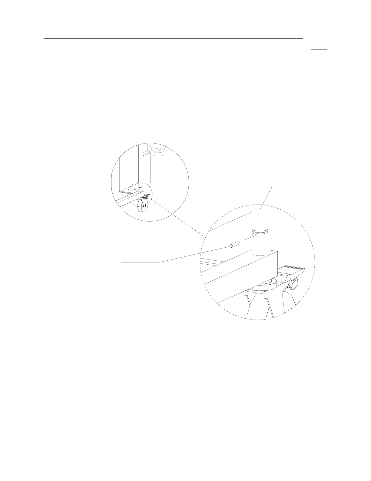
Install the stop pin as follows:
1. Locate the roll pin supplied in the drawer of the machine.
2. Rotate the swivel arm so that the hole near the bottom of the arm faces
the back of the machine.
3. Hammer the pin into the hole until it is flush with the swivel arm.
SWIVEL ARM
Selecting the
Vaporizer
Order
(Fixed Vapor
Mount
System)
PIN
SU00606
You must install the vaporizers in the following order, as viewed from the
front of the machine, unless otherwise specified by the customer:
Left position: Halothane
Center position: Enflurane
Right position: Isoflurane (or desflurane)
NOTE: To install a TEC 6 desflurane vaporizer, see Service Procedure
SP00091.
Draeger Medical, Inc. Narkomed GS Setup and Installation Manual 3-3
Page 14
3
Setup and Installation
RETURN TO THIS MANUAL'S TABLE OF CONTENTS
RETURN TO CD-ROM TABLE OF CONTENTS
Installing the
Vaporizers
(Fixed Vapor
Mount
System)
The following procedure applies to the fixed vapor mount system used on
2-vaporizer and 3-vaporizer machines, for Dräger 19.1 vaporizers.
If your machine is equipped with a removable vaporizer system, skip to the
next procedure.
Install each vaporizer as follows:
1. Remove the back cover from the vaporizer exclusion system.
2. Remove the vaporizer from its shipping container.
3. Remove the tape from the back of the vaporizer. Verify that the
vaporizer's O-rings are present at the inlet and outlet ports.
4. Unscrew the plastic plates that are mounted over the vapor ports. Save
the screws that you remove.
5. Using the saved screws from the previous step, secure the vaporizer to
the appropriate location on the manifold (see “Selecting the Vaporizer
Order” above), and tighten the screws.
WARNING: Use only the screws from the plastic plates.
6. When all vaporizers are installed, test the exclusion system for proper
operation. If adjustment is needed, refer to the Narkomed GS Service
Manual. Reinstall the back cover.
COVER SCREWS
AND
WASHERS (4X)
BACK
COVER
VAPORIZER
MOUNTING SCREWS (2X)
MANIFOLD
O-RINGS
SU00109
VAPORIZER
3-4 Narkomed GS Setup and Installation Manual Draeger Medical, Inc.
Page 15

RETURN TO THIS MANUAL'S TABLE OF CONTENTS
RETURN TO CD-ROM TABLE OF CONTENTS
Installing the
Vaporizers
(Removable
Vapor Mount
System)
Setup and Installation
3
The removable vapor mount system will accommodate Dräger 19.3 and
Dräger 2000 vaporizers.
If the customer does not specify the vaporizer positions, install the
vaporizers in the following order, as viewed from the front of the machine:
Left position: Halothane
Right position: Isoflurane
Install the vaporizers as follows:
1. Examine the ports on the vaporizer manifold and verify that each port
has an O-ring.
2. Move the selector lever to the right.
3. Place the vaporizer down over the left manifold ports, and turn its
locking lever 90
° clockwise to secure the vaporizer to the manifold.
4. Move the selector lever to the left.
5. Place the second vaporizer down over the right manifold ports, and
turn its locking lever 90
° clockwise to secure the vaporizer to the
manifold.
6. Test the interlock for proper operation. Verify that only one vaporizer
at a time can be turned on. Return all vaporizers to their Zero position
at completion of the test.
Draeger Medical, Inc. Narkomed GS Setup and Installation Manual 3-5
Page 16
3
R
G
D
Setup and Installation
RETURN TO THIS MANUAL'S TABLE OF CONTENTS
RETURN TO CD-ROM TABLE OF CONTENTS
LOCKING
LEVER
O-RINGS
VAPORIZE
MOUNTIN
MANIFOL
REMOVABLE VAPORIZER
MOUNTING ARRANGEMENT
(TOP VIEW)
SU00114
SELECTOR LEVER
3-6 Narkomed GS Setup and Installation Manual Draeger Medical, Inc.
Page 17

RETURN TO THIS MANUAL'S TABLE OF CONTENTS
RETURN TO CD-ROM TABLE OF CONTENTS
Filling a
Vaporizer
Handling the
Vaporizer
Installing the
Absorber
System
Setup and Installation
3
See the appropriate separate manual, supplied with vaporizers available
for use with the Narkomed 6000.
If a vaporizer is dropped during handling, or if its handwheel exhibits a
lack of resistance (spins freely), or if a gas analyzer maintains a zero
reading after the handwheel has been turned to a labeled concentration,
do not use the vaporizer. Return the vaporizer to DrägerService.
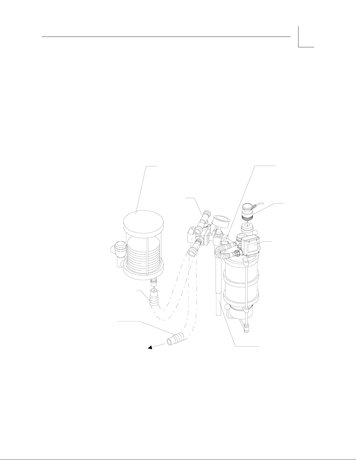
Install the absorber system as described below. This installation procedure
presumes the use of an appropriate scavenger system.
WARNING:The Narkomed GS's patient breathing system must not be
used in conjunction with any additional components that
establish a flow direction.
WARNING:Hoses and bags attached to the 22 mm hose terminals of the
inspiratory valve, expiratory valve, ventilator hose
connection, and breathing bag mount must comply with
current ANSI standards.
1. Place the absorber mounting stud into the top of the absorber pole.
2. Tighten the set screw on the absorber pole to lock the absorber in place.
WARNING:Do not pinch or kink the fresh gas hose leading from the fresh
gas common outlet to the absorber.
3. Pull out the fresh gas locking bar, located on the front of the Narkomed
GS, to its extended position. Insert the 15 mm male fitting on the fresh
gas hose axially into the 15 mm female terminal. Release the springloaded locking bar over the fitting, allowing it to “lock” the fitting into
place.
WARNING:To prevent leaks and misdirection of gas pathways, all hoses
should be correctly and tightly fitted, as shown in the
illustrations. Take special care to attach all 19 mm hoses to
the proper 19 mm connectors. Possible machine malfunction
and harm to the patient could occur if the scavenger hoses are
attached to any 22 mm connection.
4. Attach a 22 mm breathing hose between the ventilator bellows 22 mm
terminal marked VENTILATOR HOSE, and the 22 mm terminal on
the rear of the manual/automatic selector valve marked VENTILATOR
HOSE.
Draeger Medical, Inc. Narkomed GS Setup and Installation Manual 3-7
Page 18
3
Setup and Installation
RETURN TO THIS MANUAL'S TABLE OF CONTENTS
RETURN TO CD-ROM TABLE OF CONTENTS
5. Attach a 22 mm breathing hose betwen the 22 mm hose terminal on
the inspiratory valve marked INSPIRATION, and one side of the
Y-piece.
WARNING:To ensure proper gas flow direction during inspiration and
expiration, the disks in the inspiratory and expiratory valves
must move freely, without sticking.
6. Attach a 22 mm breathing hose between the other side of the Y-piece
and the expiratory hose terminal on the ultrasonic flow sensor.
7. Attach the breathing bag to the swivel bag mount 22 mm terminal
marked BREATHING BAG.
ULTRASONIC
FLOW SENSOR
W/22MM BREATHING
HOSE TERMINAL
INSPIRATORY
VALVE W/22MM
BREATHING
HOSE TERMINAL
22MM
BREATHING
HOSES
(P/N 9995132)
ABSORBER
ABSORBER
MOUNTING
STUD
EXPIRATORY
VALVE
APL VALVE W/19MM
SCAVENGER HOSE
TERMINAL
19MM SCAVENGER
HOSE
MANUAL/AUTOMATIC
SELECTOR VALVE
W/22MM HOSE TERMINAL
LOCKING DEVICE
W/15MM FEMALE
FRESHGAS HOSE
(P/N 9995230)
TO SCAVENGER
SET SCREW
(P/N HW10002)
FRESHGAS
FITTING
W/15MM MALE
FITTING
Y-PIECE
SWIVEL BAG MOUNT W/22MM
BREATHING BAG TERMINAL
SU14718B
3-8 Narkomed GS Setup and Installation Manual Draeger Medical, Inc.
BREATHING BAG
ABSORBER POLE
Page 19
RETURN TO THIS MANUAL'S TABLE OF CONTENTS
RETURN TO CD-ROM TABLE OF CONTENTS
Setup and Installation
WARNING:The breathing bag acts as a pressure limiting device during
manually assisted and spontaneous ventilation. Therefore,
breathing bags used with the Absorber system must comply
with the pressure/volume requirements of current ANSI
standards. A bag that has been stretched may have
drastically altered compliance characteristics, and altered
conductivity in the case of conductive bags.
8. Connect the 19 mm scavenger hose between the 19 mm terminal
marked SCAVENGER HOSE on the rear of the APL valve and the
19 mm terminal marked SCAVENGER HOSE on the scavenger.
VENTILATOR BELLOWS
W/22MM VENTILATOR
HOSE TERMINAL
SU98101B
APL
VALVE
PRESSURE
SENSING PORT
QUICK-CONNECT
FITTING
OXYGEN
SENSOR
3
VENTILATOR
22MM
BREATHING
HOSE
19MM
SCAVENGER
HOSE
TO SCAVENGER
ULTRASONIC
FLOW SENSOR
ABSORBER POLE
Draeger Medical, Inc. Narkomed GS Setup and Installation Manual 3-9
Page 20
3
Setup and Installation
RETURN TO THIS MANUAL'S TABLE OF CONTENTS
RETURN TO CD-ROM TABLE OF CONTENTS
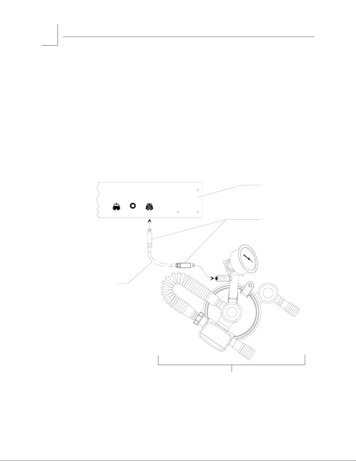
Installing the
Breathing
Pressure
Pilot Line
For Absorber
Monitoring
Draeger Medical anesthesia systems are supplied with two breathing
pressure pilot lines:
• A short line for breathing pressure monitoring at the absorber
• A long line for breathing pressure monitoring at the Y-piece
For breathing pressure monitoring at the absorber, install the short pilot
line (which has quick-connect fittings on both ends) as follows:
1. Connect one end of the pilot line to the fitting mounted on the rear of
the pipe extending from the absorber top assembly.
2. Connect the other end of the pilot line to the BREATHING PRESSURE
interface underneath the rear panel of the ventilator box.
REAR PANEL OF
VENTILATOR BOX
VOLUME
SENSOR
2
OXYGEN
SENSOR
BREATHING
PRESSURE
AUTO/BAG
SELECTOR
QUICK-CONNECT
FITTINGS
SHORT
PILOT LINE
(P/N 4109368)
SU00603A
ABSORBER
TOP ASSEMBLY
3-10 Narkomed GS Setup and Installation Manual Draeger Medical, Inc.
Page 21
RETURN TO THIS MANUAL'S TABLE OF CONTENTS
RETURN TO CD-ROM TABLE OF CONTENTS
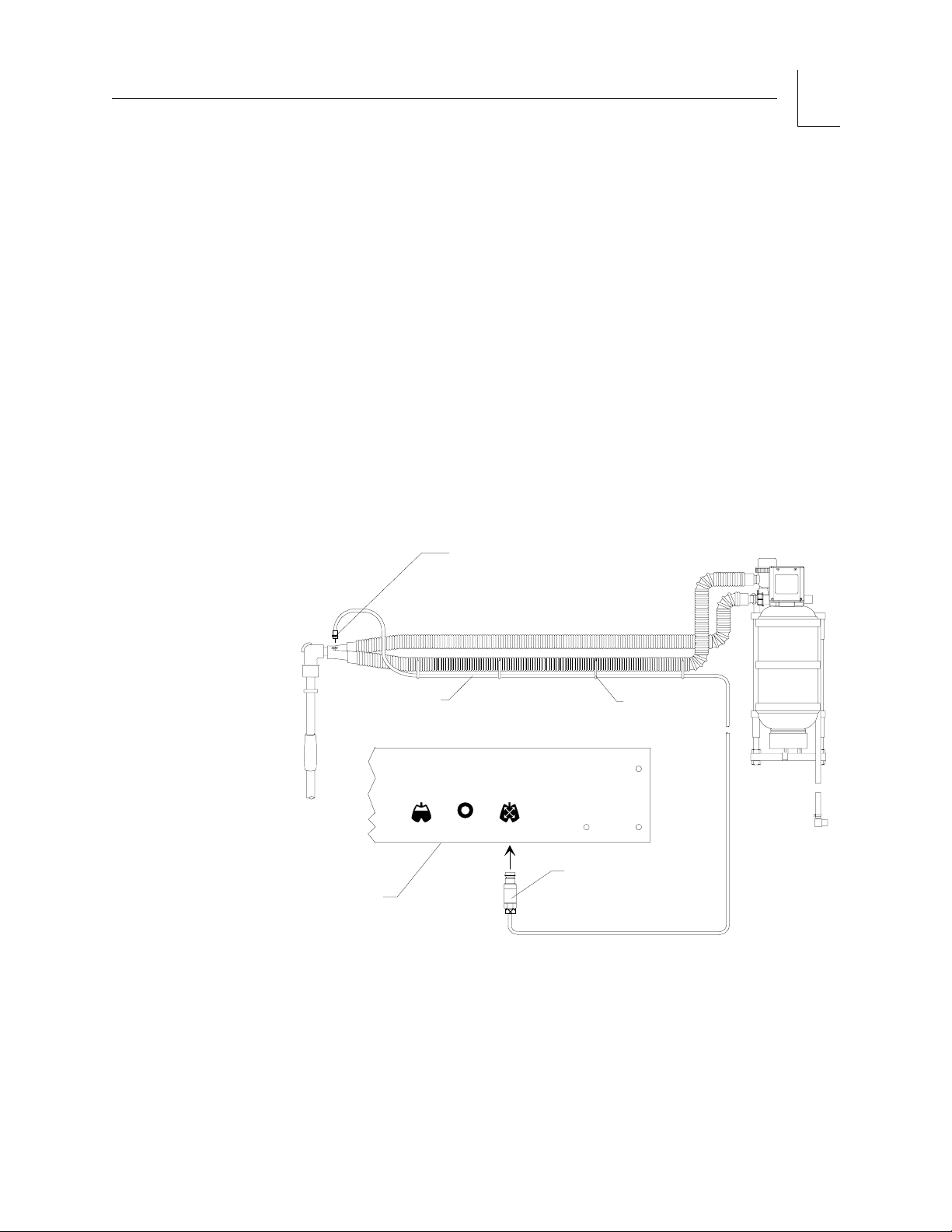
For Y-piece
Monitoring
Setup and Installation
3
For breathing pressure monitoring at the patient Y-piece, install the long
pilot line (which has a quick-connect fitting on one end and a Luer type
fitting on the other end) as follows:
1. Connect the quick-connect fitting on the pilot line to the BREATHING
PRESSURE interface underneath the rear panel of the ventilator box.
NOTE: The quick-connect fitting on the absorber is self-closing. You can
leave it unused when installing the long pilot line for
Y-piece monitoring.
2. Connect the Luer fitting on the other end of the pilot line to a Luer
fitting on either the patient Y-piece or a 15 mm adapter on the patient
side of the Y-piece.
3. Using the four plastic hose clips attached to the pilot line, mount the
pilot line on either of the breathing hoses leading to the Y-piece.
PILOT LINE
(P/N 4108528)
REAR PANEL OF
VENTILATOR BOX
LONG
VOLUME
SENSOR
MALE
LUER-LOCK
FITTING
2
OXYGEN
BREATHING
SENSOR
PRESSURE
PLASTIC
HOSE CLIPS
AUTO/BAG
SELECTOR
QUICK-CONNECT
FITTING
SU00604A
Draeger Medical, Inc. Narkomed GS Setup and Installation Manual 3-11
Page 22

3
Setup and Installation
RETURN TO THIS MANUAL'S TABLE OF CONTENTS
RETURN TO CD-ROM TABLE OF CONTENTS
Installing the
AUTO/BAG
Sensor Cord
1. Push the manual/automatic selector sensor into the underside of the
manual/automatic selector valve housing until it snaps into place. Note
that the sensor is keyed and only fits into the housing one way.
2. Align the key on the sensor cord connector with the keyway on the
AUTO/BAG SELECTOR interface underneath the ventilator box. Then
push the connector in until it snaps into place.
REAR PANEL OF
VENTILATOR BOX
SU00602
VOLUME
SENSOR
SENSOR CORD
CONNECTOR
2
OXYGEN
SENSOR
BREATHING
PRESSURE
AUTO/BAG
SELECTOR
INTERFACE
CABLE
MANUAL/
AUTOMATIC
SELECTOR
VALVE
MANUAL/
AUTOMATIC
SELECTOR
SENSOR
3-12 Narkomed GS Setup and Installation Manual Draeger Medical, Inc.
Page 23

Y
Y
RETURN TO THIS MANUAL'S TABLE OF CONTENTS
RETURN TO CD-ROM TABLE OF CONTENTS
Installing the
Oxygen
Sensor
Setup and Installation
3
1. Remove the inspiratory valve dome plug from the inspiratory valve
dome.
2. Insert the sensor cord connector into the OXYGEN SENSOR interface
underneath the rear panel of the ventilator box.
3. Remove any protective covering from the sensor housing.
4. Perform an oxygen sensor calibration as described in “Operation Oxygen Monitoring” in the
Narkomed GS Operator's Manual.
5. Insert the sensor assembly into the inspiratory valve dome by pressing
it into place.
SENSOR
REAR PANEL OF
VENTILATOR BOX
HOUSING
VOLUME
SENSOR
2
OXYGEN
SENSOR
BREATHING
AUTO/BAG
PRESSURE
SELECTOR
SENSOR
CORD
CONNECTOR
INSPIRATOR
VALVE DOME
INSPIRATOR
VALVE DOME
PLUG
(P/N 4106387)
SU00601
Draeger Medical, Inc. Narkomed GS Setup and Installation Manual 3-13
Page 24

3
Setup and Installation
RETURN TO THIS MANUAL'S TABLE OF CONTENTS
RETURN TO CD-ROM TABLE OF CONTENTS
Installing the
Ultrasonic
Flow Sensor
1. Slide the flow sensor down onto the bracket attached to the expiratory
valve mount.
2. Install the connector hose on the threaded port of the flow sensor, and
join the other end of the hose to the expiratory valve. Ensure that the
expiratory valve is oriented as shown in the illustration below.
3. Connect the sensor plug to the VOLUME SENSOR interface on the
rear panel of the ventilator box.
2
SENSOR
PLUG
ULTRASONIC
FLOW SENSOR
CONNECTOR
HOSE
EXPIRATORY
HOSE TERMINAL
FLOW SENSOR
BRACKET
EXPIRATORY VALVE
ABSORBER
ASSEMBLY
SU00009A
3-14 Narkomed GS Setup and Installation Manual Draeger Medical, Inc.
Page 25

RETURN TO THIS MANUAL'S TABLE OF CONTENTS
RETURN TO CD-ROM TABLE OF CONTENTS
Installing the
Bain Circuit
Adapter
(Optional)
Absorber
Mount
Setup and Installation
3
Two types of Bain circuit adapters are available. One mounts to the
absorber; the other mounts to the pole.
To install the absorber-mounted Bain Circuit Adapter, slip the mounting
bracket of the Bain Circuit Adapter down over the slide mount on the
absorber assembly (on the block below the APL valve).
WARNING:To avoid confusion between hose terminals on the absorber
system and the Bain Circuit Adapter, always remove the Bain
Circuit Adapter from the absorber mount when the Bain
Circuit Adapter is not in use.
TO BREATHING
PRESSURE MONITOR
INTERFACE PANEL
APL VALVE
TO 19MM HOSE TERMINAL
ON SCAVENGER
OXYGEN
SENSOR
22MM
M/15MM F
EXPIRATION
TERMINAL
BAIN
CIRCUIT
BAIN CIRCUIT
HOSE BARB FOR
FRESH GAS HOSE
ABSORBER
APL VALVE
BAIN CIRCUIT
ADAPTER
BREATHING
BAG
SU14730A
Draeger Medical, Inc. Narkomed GS Setup and Installation Manual 3-15
FRESH GAS
OUTLET
Page 26
RETURN TO THIS MANUAL'S TABLE OF CONTENTS
RETURN TO CD-ROM TABLE OF CONTENTS
3
Setup and Installation
Pole Mount The Bain Circuit Adapter that mounts on the absorber pole may be
supplied with an optional positive end-expiratory pressure (PEEP) valve.
To install a pole-mounted Bain Circuit Adapter, with or without a PEEP
valve:
1. Loosen the set screw on the absorber pole and remove the absorber
system (if the machine is so equipped).
2. Slip the Bain Circuit Adapter mounting stud into the absorber pole.
3. Tighten the set screw on the absorber pole to lock the Bain Circuit
Adapter in place.
BREATHING
PRESSURE
PILOT LINE
BAIN
CIRCUIT
BAIN
CIRCUIT
HOSE BARB
FOR FRESH
GAS HOSE
MOUNTING
STUD
OXYGEN
SENSOR
19 MM SCAVENGER HOSE
(P/N 9995230)
(CONNECTS TO 19MM
TERMINAL ON SCAVENGER)
22MM HOSE
(P/N 9995123)
(CONNECTS TO
VENTILATOR HOSE
TERMINAL ON
VENTILATOR
BELLOWS ASSEMBLY)
SET SCREW
FRESH GAS
COMMON
OUTLET
BREATHING
FRESH GAS
HOSE
SU14719A
3-16 Narkomed GS Setup and Installation Manual Draeger Medical, Inc.
BAG MOUNT
BREATHING BAG
Page 27

RETURN TO THIS MANUAL'S TABLE OF CONTENTS
RETURN TO CD-ROM TABLE OF CONTENTS
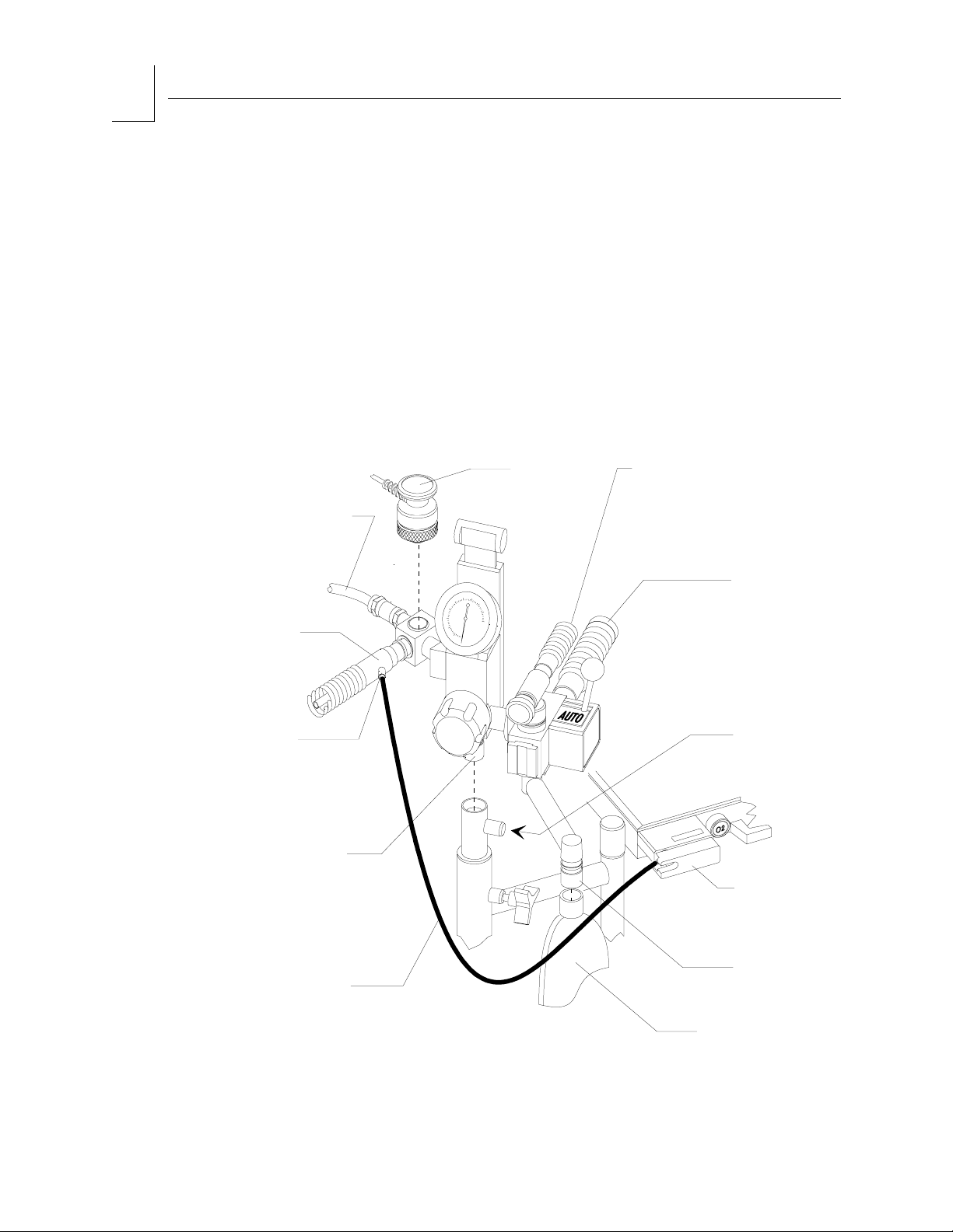
Bain Circuit
Oxygen
Sensor
Installation
Setup and Installation
3
1. Insert the oxygen sensor into the port adjacent to the expiratory
terminal. When the port is not in use, close it with the provided plug.
Insert the sensor cable into the OXYGEN SENSOR interface as
described earlier in this section.
WARNING:A functioning oxygen analyzer must always be used with the
Bain Circuit Adapter.
2. Connect the breathing pressure pilot line to the quick-connect fitting
on the bain circuit adapter. Insert the other end of the pilot line into
the BREATHING PRESSURE interface as described earlier in this
section.
WARNING:A functioning breathing pressure monitor must always be
used with the Bain Circuit Adapter.
3. Bain Circuit ConnectionsInstall the breathing bag onto the terminal
labeled BREATHING BAG.
WARNING:Breathing bags attached to the Bain Circuit Adapter's 22 mm
terminals must comply with current ANSI standards.
4. Connect the 19 mm scavenger hose between the 19 mm terminal at the
rear of the APL valve marked SCAVENGER HOSE and the 19 mm
terminal on scavenger.
5. If applicable, connect a 22 mm hose between the terminal on the rear of
the manual/automatic selector valve, and the VENTILATOR HOSE
terminal on the bottom of the ventilator bellows assembly.
WARNING:Hoses connected to the Bain Circuit Adapter terminals must
comply with current ANSI standards.
6. Connect the Bain Circuit to the 22 mm male/15 mm female terminal on
the Bain Circuit Adapter marked EXPIRATION.
7. Connect the fresh gas hose between the fresh gas outlet on the
Narkomed GS, and the hose barb fitting on the Bain Circuit (inner
tube connection).
8. Set the APL valve fully open, set the PEEP valve (if supplied) at
minimum, and set the Man/Auto selector to BAG.
WARNING:The fresh gas hose must not be pinched or kinked.
Draeger Medical, Inc. Narkomed GS Setup and Installation Manual 3-17
Page 28

3
Setup and Installation
RETURN TO THIS MANUAL'S TABLE OF CONTENTS
RETURN TO CD-ROM TABLE OF CONTENTS
Installing the
Fresh Gas
Oxygen
Sensor
Adapter
(Optional)
1. Hold the locking bar on the anesthesia machine's fresh gas outlet in
the extended position.
2. With the oxygen sensor port facing up, slide the notched portion of the
adapter stem into the retaining slot of the locking bar, so that the
adapter's 15 mm male fitting faces the anesthesia machine's fresh gas
outlet.
3. Release the locking bar, guiding the adapter's 15 mm male fitting into
the fresh gas outlet of the anesthesia machine.
4. Insert the oxygen sensor into the port on top of the adapter.
WARNING:If the oxygen sensor is removed, the oxygen sensor port must
be closed with the oxygen sensor port plug.
5. Attach the non-rebreathing circuit fresh gas hose to the adapter's
barbed fitting. (For non-rebreathing circuits equipped with a 15 mm
fresh gas connector, cut off the connector and press the hose onto the
barbed fitting of the adapter.)
FRESH GAS
OUTLET
OXYGEN
SENSOR
15MM MALE
FITTING
ADAPTER
STEM
OXYGEN
SENSOR PLUG
SU20997
FRESH GAS
LOCKING BAR
(EXTENDED POSITION)
OXYGEN SENSOR PORT
FRESH GAS HOSE
BARBED FITTING FOR
NON-REBREATHING
GAS CIRCUIT
3-18 Narkomed GS Setup and Installation Manual Draeger Medical, Inc.
Page 29

RETURN TO THIS MANUAL'S TABLE OF CONTENTS
RETURN TO CD-ROM TABLE OF CONTENTS
Connecting
the Open
Reservoir
Scavenger
System
(Optional)
Setup and Installation
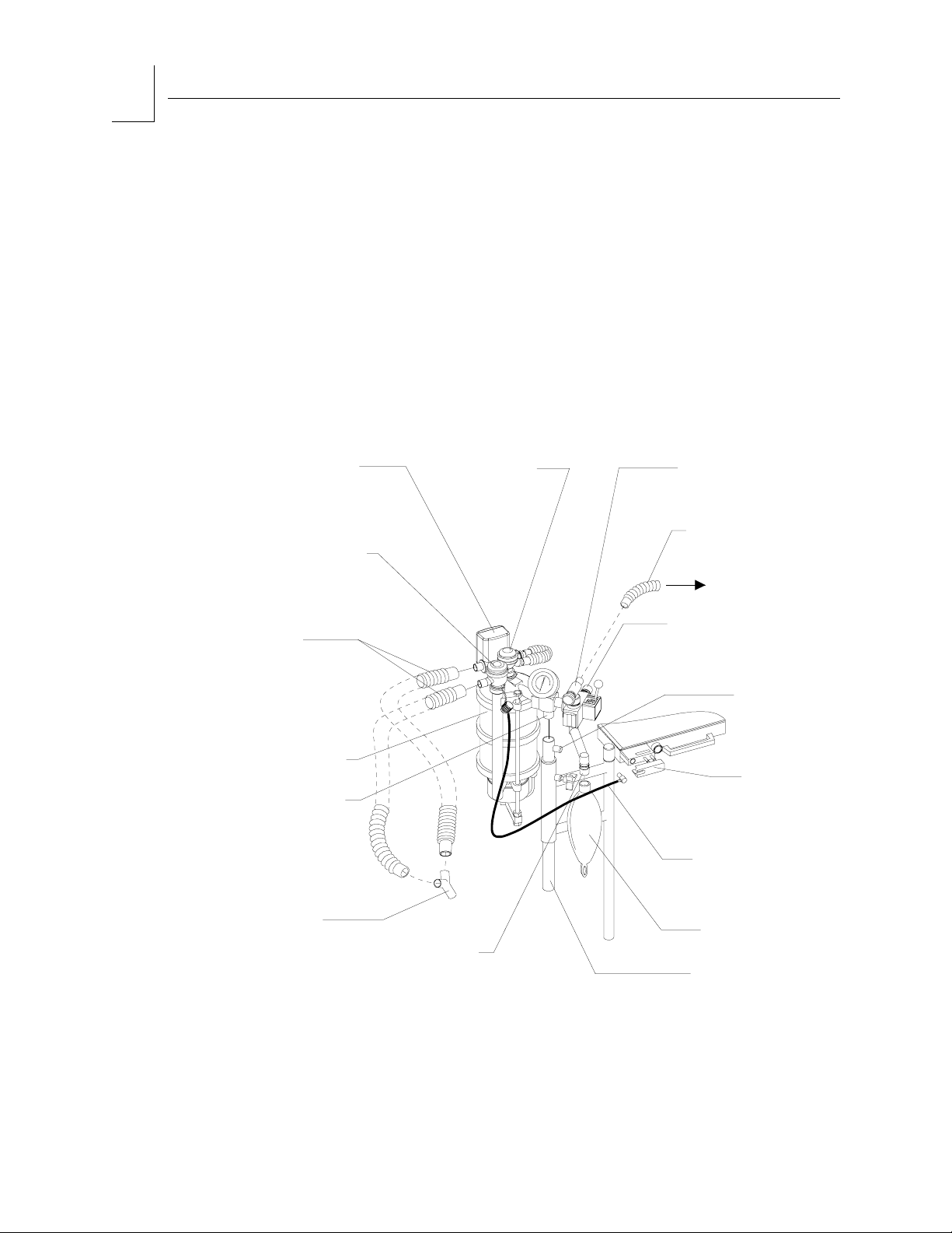
The Open Reservoir Scavenger is installed on the Narkomed GS before
shipping. The scavenger hose connections are described below.
CAUTION: Take special care not to accidentally force 19 mm scavenger
hoses over 22 mm breathing hose terminals. Carefully follow
the hose connection instructions for installing the scavenger
and the absorber.
1. Connect a 19 mm scavenger hose between the 19 mm terminal
(marked SCAVENGER HOSE) on the rear of the APL valve and the 19
mm terminal (marked SCAVENGER HOSE) on the right side of the
scavenger.
WARNING:The 19 mm scavenger hose leading from the absorber must
not be pinched, kinked, or blocked in any manner.
VENTILATOR
RELIEF VALVE
19MM SCAVENGER
HOSE TERMINAL
APL VALVE
3
19MM
SCAVENGER
HOSE
(P/N 9995230)
19MM SCAVENGER
HOSE TERMINAL
OPEN RESERVOIR
SCAVENGER
ABSORBER
POLE
SU14716B
19MM SCAVENGER
HOSE
(P/N 9995230)
VACUUM TERMINAL
Draeger Medical, Inc. Narkomed GS Setup and Installation Manual 3-19
Page 30

3
Setup and Installation
RETURN TO THIS MANUAL'S TABLE OF CONTENTS
RETURN TO CD-ROM TABLE OF CONTENTS
2. Connect another 19 mm scavenger hose between the 19 mm terminal
(marked SCAVENGER HOSE) on the ventilator relief valve and the 19
mm terminal (marked SCAVENGER HOSE) on the left side of the
scavenger.
WARNING:The 19 mm scavenger hose leading from the ventilator relief
valve must not be pinched, kinked, or blocked in any manner.
3. Connect a wall suction hose between the wall suction outlet and the
suction terminal (DISS fitting or hose barb with adapter) on the
scavenger.
Connecting
the
Scavenger
Interface for
Passive
Systems
(Optional)
The Scavenger Interface for Passive Systems is installed on the
Narkomed GS before shipping. The scavenger hose connections are
described below.
CAUTION: Take special care not to accidentally force 19 mm scavenger
hoses over 22 mm breathing hose terminals. Carefully follow
the hose connection instructions for installing the scavenger
and the absorber.
1. Connect a 19 mm scavenger hose between the 19 mm terminal
(marked SCAVENGER HOSE) on the rear of the APL valve and the
19 mm terminal (marked SCAVENGER HOSE) on the right side of the
scavenger.
WARNING:The 19 mm scavenger hose leading from the absorber must
not be pinched, kinked, or blocked in any manner.
2. Connect another 19 mm scavenger hose between the 19 mm terminal
(marked SCAVENGER HOSE) on the ventilator relief valve and the 19
mm terminal (marked SCAVENGER HOSE) on the left side of the
scavenger.
WARNING:The 19 mm scavenger hose leading from the ventilator relief
valve must not be pinched, kinked, or blocked in any manner.
3-20 Narkomed GS Setup and Installation Manual Draeger Medical, Inc.
Page 31

RETURN TO THIS MANUAL'S TABLE OF CONTENTS
RETURN TO CD-ROM TABLE OF CONTENTS
VENTILATOR
RELIEF VALVE
19MM SCAVENGER
HOSE TERMINAL
APL VALVE
19MM SCAVENGER
HOSE
(P/N 9995230)
Setup and Installation
ABSORBER POLE
3
SCAVENGER INTERFACE
FOR NON-ACTIVE SYSTEMS
19MM SCAVENGER
HOSE
(P/N 9995230)
SU14717B
TO HOSPITAL
EXHAUST SYSTEM
NOTE: If only one of the 19 mm hose terminals will be used, the unused
terminal should be capped with the provided input port cap.
3. Connect another 19 mm scavenger hose between the 19 mm terminal
labeled EXHAUST (on the bottom of the scavenger) and the hospital
exhaust system grill adapter.
Draeger Medical, Inc. Narkomed GS Setup and Installation Manual 3-21
Page 32

3
Setup and Installation
RETURN TO THIS MANUAL'S TABLE OF CONTENTS
RETURN TO CD-ROM TABLE OF CONTENTS
Installing the
Patient Line
Boom Arm
(Optional)
1. 1.Assemble the patient line boom arm and support plate as illustrated,
with two
d-24 x 2¾ in. flat head socket screws.
2. 2.Position the assembly at the left side of the machine, and attach the
support plate to the machine with four ¼-20 x
f in. button head socket
screws and lock washers. If the machine was ordered with a manual
sphygmomanometer, use a ¼-20 x
d in. button head socket screw
through the gauge mount at the lower front corner of the support plate.
3. 3.Install two ¼-20 x 1¾ in socket head cap screws through the patient
line boom arm block and support plate into the machine.
PATIENT LINE
BOOM ARM
3/8-24 X 2 3/4 IN.
FLAT HEAD
SOCKET SCREW (2X)
1/4 - 20 X 3/4 IN.
SOCKET HEAD
CAP SCREW (2X)
SU87030
AND LOCK WASHER (4X)
3-22 Narkomed GS Setup and Installation Manual Draeger Medical, Inc.
SUPPORT PLATE
1/4-20 X 7/8 IN. BUTTON
HEAD SOCKET SCREW
Page 33

RETURN TO THIS MANUAL'S TABLE OF CONTENTS
RETURN TO CD-ROM TABLE OF CONTENTS
Installing the
Manual
Sphygmomanometer
Gauge
(optional)
Setup and Installation
1. Remove the protective cap covering the threads of the gauge mount,
located at the boom arm support plate on the left side of the anesthesia
machine.
2. Screw the manual sphygmomanometer gauge mounting ring tightly
onto the gauge mount, oriented with the gauge facing forward.
3
GAUGE
MOUNT
THREADED
MOUNTING
RING
MANUAL
SPHYGMOMANOMETER
GAUGE
SU87032
Draeger Medical, Inc. Narkomed GS Setup and Installation Manual 3-23
Page 34

3
Setup and Installation
RETURN TO THIS MANUAL'S TABLE OF CONTENTS
RETURN TO CD-ROM TABLE OF CONTENTS
3. Connect the gauge hose to the BP GAUGE fitting on the interface
panel.
4. Connect the cuff extension hose to the BP CUFF fitting on the interface
panel. Connect the other end of the cuff extension hose to a blood
pressure cuff. Refer to the Narkomed GS Operator's Instruction
Manual for selecting the correct size blood pressure cuff.
5. Connect an inflation bulb to the female luer fitting labeled BP BULB
on the front of the machine.
THREADED HOSE FITTINGS
FOR GAUGE AND CUFF
SU00605
BP CUFF
INTERNAL PIPING
CONNECTS BULB FITTING
TO GAUGE AND CUFF FITTING
O2 FLUSH
SPHYGMOMANOMETER
GAUGE
FEMALE LUER FITTING
(SLIP-FIT) FOR CUFF
INFLATION BULB
FRONT OF FRAMEHANDLE
3-24 Narkomed GS Setup and Installation Manual Draeger Medical, Inc.
Page 35

RETURN TO THIS MANUAL'S TABLE OF CONTENTS
RETURN TO CD-ROM TABLE OF CONTENTS
Installing the
Second Shelf
(Optional)
Setup and Installation
3
Several height configurations (distance between the top of the ventilator
box and the second shelf) are possible.
1. Select the desired height configuration and install the second shelf
assembly as illustrated.
For the 3 ½ in. and 6 ¼ in. configurations, the second shelf assembly is
installed directly to the machine.
For the 9 in., 11 ¾ in., and 14 ½ in. configurations, two extender
brackets must be used.
SHELF ASSEMBLY
(4) 1" LG BUTTON HEAD
CAP SCREW
3 1/2"
6 1/4"
3 1/2" HEIGHT CONFIGURATION
(4) 1" LG BUTTON HEAD
CAP SCREW
SU87029
6 1/4" HEIGHT CONFIGURATION
Draeger Medical, Inc. Narkomed GS Setup and Installation Manual 3-25
Page 36

3
Setup and Installation
(4) ACORN NUT
(4) SPLIT LOCK WASHER
(4) FLAT WASHER
(4) HEX HEAD SCREW
RETURN TO THIS MANUAL'S TABLE OF CONTENTS
RETURN TO CD-ROM TABLE OF CONTENTS
(4) ACORN NUT
(4) SPLIT LOCK WASHER
(4) FLAT WASHER
(4) HEX HEAD SCREW
9 "
(2) EXTENDER BRACKET
(4) 1" LG BUTTON HEAD
CAP SCREW
9" HEIGHT CONFIGURATION
9" HEIGHT CONFIGURATION
(4) HEX HEAD SCREW
11 3/4"
(2) EXTENDER BRACKET
(4) 1" LG BUTTON HEAD
CAP SCREW
11 3/4" HEIGHT CONFIGURATION
(4) FLAT
WASHER
(4) SPLIT LOCK
WASHER
14 1/2"
(4) ACORN NUT
(2) EXTENDER BRACKET
(4) 1" LG BUTTON HEAD
CAP SCREW
SU87028
3-26 Narkomed GS Setup and Installation Manual Draeger Medical, Inc.
14 1/2" HEIGHT CONFIGURATION
Page 37

RETURN TO THIS MANUAL'S TABLE OF CONTENTS
RETURN TO CD-ROM TABLE OF CONTENTS
Installing the
Shelf
Extender
(Optional)
Setup and Installation
3
The shelf extender can be installed with several machine configurations,
as shown in the accompanying illustrations.
1. Remove the clip board hook from the right side of the vapor box, and
remove the vapor box push/pull bar if the machine is so equipped.
2. Position the shelf extender at the right side of the machine and attach
the extender to the ventilator box with two 8-32 x
screws, and one 5/16-24 x
e in. button head screw.
d in. button head
3. Reinstall the clip board hook with two 10-32 x ½ in. button head
screws.
4. If the machine is equipped with a vapor box push/pull bar, reinstall the
bar with four 10-32 x
f in. socket head cap screws.
If the machine is not equipped with a vapor box push/pull bar, install
10-32 x ½ in. button head screws at these four locations.
Draeger Medical, Inc. Narkomed GS Setup and Installation Manual 3-27
Page 38

3
Setup and Installation
RETURN TO THIS MANUAL'S TABLE OF CONTENTS
RETURN TO CD-ROM TABLE OF CONTENTS
SU87027
SHELF
EXTENDER
CLIP BOARD
HOOK
(2)SCREW-BUTTON
HD SKT
8-32 X 3/8 SS BO
(1)SCREW-BUTTON
HD SKT
5/16-24 X 5/8 SS BO
(6)SCREW-BUTTON
HD SKT
10-32 X 1/2 SS BO
CONFIGURATION WITHOUT PUSH/PULL BAR
(2)SCREW-BUTTON HD SKT
8-32 X 3/8 SS BO
SHELF
EXTENDER
CLIP BOARD
HOOK
PUSH/ PULL
BAR
(1)SCREW-BUTTON
HD SKT
5/16-24 X 5/8 SS BO
(2)SCREW-BUTTON
HD SKT
10-32 X 1/2 SS BO
(4)SCREW-CAP
SKT HD
10-32 X 7/8 SS
CONFIGURATION WITH PUSH/PULL BAR
3-28 Narkomed GS Setup and Installation Manual Draeger Medical, Inc.
Page 39

RETURN TO THIS MANUAL'S TABLE OF CONTENTS
RETURN TO CD-ROM TABLE OF CONTENTS
Installing the
Outlet Strip
(Optional)
Setup and Installation
3
1. Fasten the two outlet strip mounting clips to the vapor box bottom
access plate with 8-32 x ¼ in. pan head screws.
2. Slide the outlet strip onto the mounting clips. Be sure that the clips
engage both mounting rails on the outlet strip housing.
3. Connect the outlet strip power cord to a hospital grade outlet only. DO
NOT connect the power cord to the convenience receptacles on the
anesthesia machine.
REAR VIEW OF
ANESTHESIA MACHINE
WHEN USING THIS OUTLET STRIP....
SU87031
MOUNTING
CLIP (2X)
MOUNTING
SCREW (2X)
(P/N HW02014)
U
L
OUTLET
STRIP
Draeger Medical, Inc. Narkomed GS Setup and Installation Manual 3-29
Page 40

RETURN TO THIS MANUAL'S TABLE OF CONTENTS
RETURN TO CD-ROM TABLE OF CONTENTS
Page 41

RETURN TO THIS MANUAL'S TABLE OF CONTENTS
RETURN TO CD-ROM TABLE OF CONTENTS
4
Gas Supply Connections
Section contents:
Gas Supply Connections ..................................................... 4-2
Connecting the Cylinders .................................................... 4-3
Connecting the Pipelines..................................................... 4-4
Draeger Medical, Inc. Narkomed GS Setup and Installation Manual
Page 42

4
Gas Supply Connections
RETURN TO THIS MANUAL'S TABLE OF CONTENTS
RETURN TO CD-ROM TABLE OF CONTENTS
Gas Supply
Connections
The gas supply connections on the anesthesia machine are shown in the
following illustration. Details of the cylinder yokes and pipeline
connections are given in the following pages.
SU87024
PIPELINE
SUPPLY
GAS FITTINGS
N2O
YOKES
O
YOKE
2
3RD GAS
YOKE
Color Coding Each connection, valve, gauge, and flowmeter is labeled and color-coded for
the appropriate gas. Color codes for the USA, ISO, and Germany are
shown in the following table.
GAS SYSTEM COLOR CODING
GAS MARKING USA ISO GERMANY
Air AIR Yellow
Carbon Dioxide CO
Nitrous Oxide N
Oxygen O
2
O Blue Blue Gray
2
2
Gray Gray Black
Green White Blue
Black/White
Checkered
Yello w
4-2 Narkomed GS Setup and Installation Manual Draeger Medical, Inc.
Page 43

RETURN TO THIS MANUAL'S TABLE OF CONTENTS
RETURN TO CD-ROM TABLE OF CONTENTS
Connecting
the Cylinders
Gas Supply Connections
4
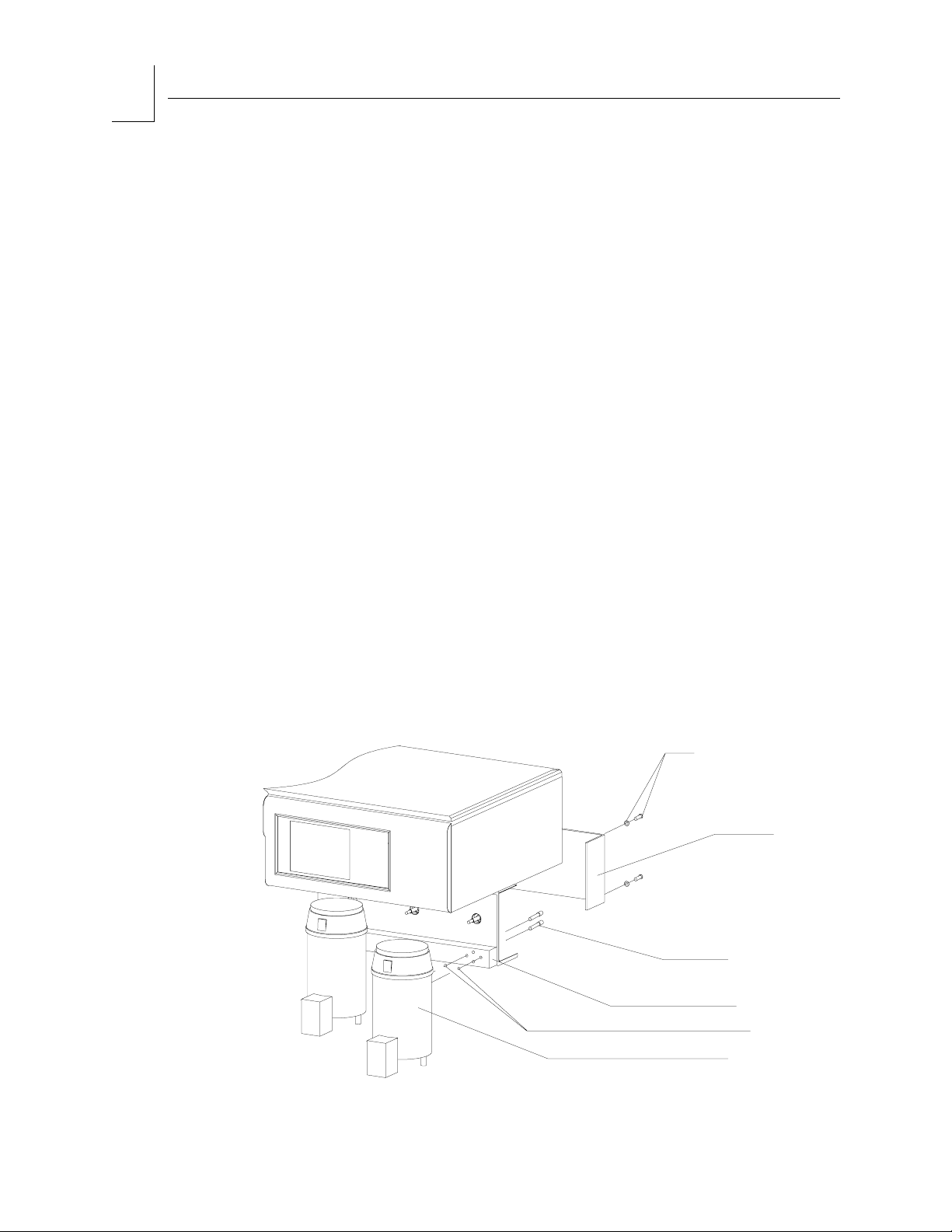
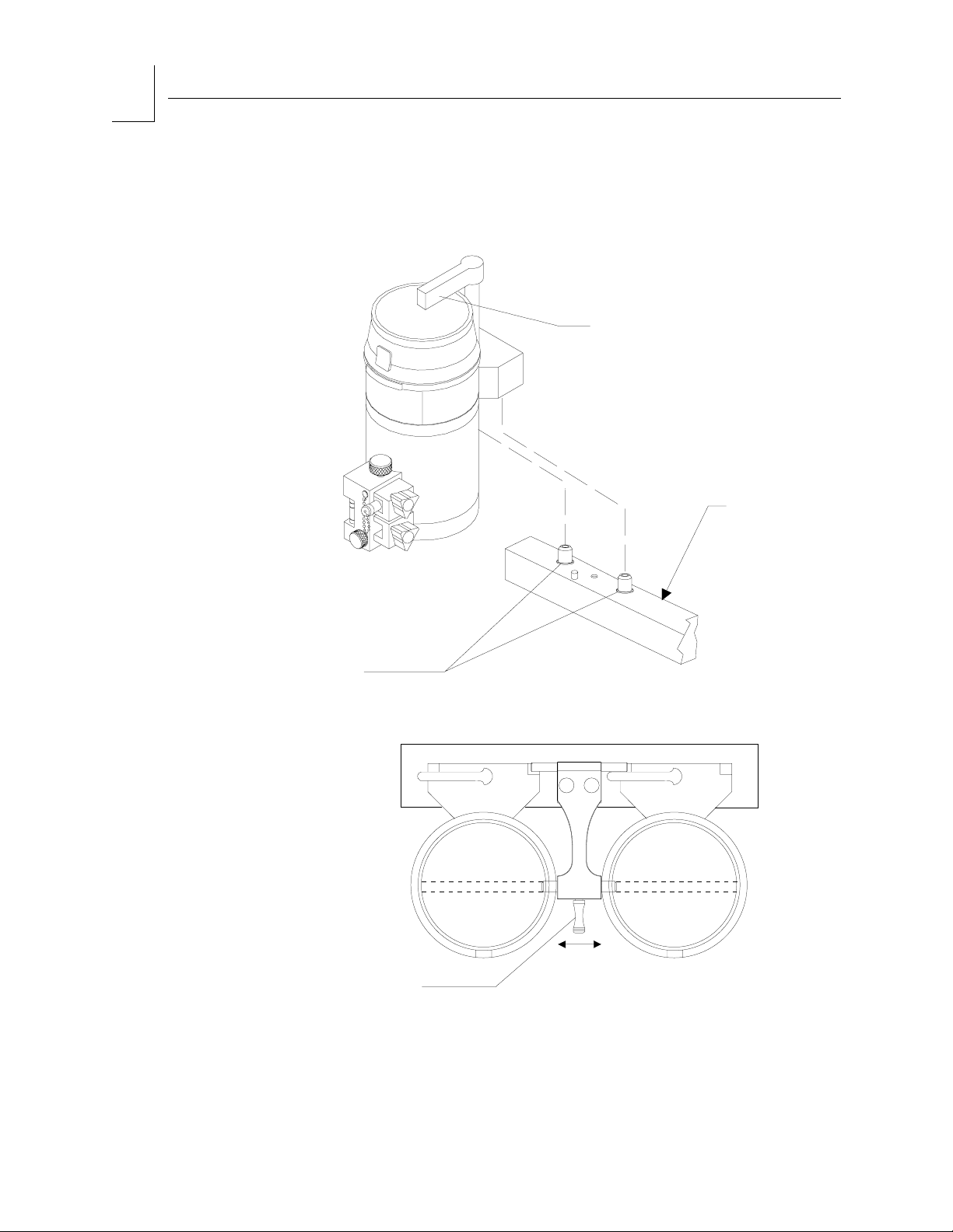
The Narkomed GS is equipped with ANSI standard pin-indexed hanger
yokes for E-size gas cylinders.
WARNING:Oil and grease may combine explosively with oxygen or
nitrous oxide. For this reason, oil and grease must never come
in contact with pipelines, cylinders, cylinder valves, gauges,
fittings, etc., which conduct oxygen or nitrous oxide within the
machine. For further information regarding safety
precautions in the use of medical gases, consult Compressed
Gas Association pamphlet P-2 and appropriate sections of
National Fire Protection Association Standard 99.
Attach cylinders as follows:
1. Place a new washer on the seat of the yoke gas inlet connection.
WARNING:Use only one cylinder washer per yoke. Using more than one
washer could cause leakage of the cylinder gas and
compromise the pin indexing system.
2. Verify the presence and integrity of the two index pins below the gas
inlet.
WARNING:Check cylinder yokes for the presence of two index pins each
time a cylinder is attached to the machine.
3. Insert the head of a gas cylinder with matching gas into the yoke from
below, so that the gas outlet and indexing holes on the cylinder head
are facing the gas inlet and indexing pins on the yoke. (See the “Gas
System Color Coding” table at the beginning of this section.)
4. Engage the indexing holes with the index pins. Screw the yoke handle
clockwise against the cylinder head, so that the point of the yoke
handle bolt is aligned with the countersunk recess on the back of the
cylinder head.
5. Verify that the sealing washer is in place, that the index pins are
engaged, and that the cylinder hangs vertically. Tighten the handle
securely.
Draeger Medical, Inc. Narkomed GS Setup and Installation Manual 4-3
Page 44

4
Gas Supply Connections
RETURN TO THIS MANUAL'S TABLE OF CONTENTS
RETURN TO CD-ROM TABLE OF CONTENTS
Connecting
the Pipelines
YOKE HANDLE
BOLT
YOKE PLUG
YOKE
HANDLE
CYLINDER
WRENCH
SU20035A
YOKE
ASSEMBLY
INDEX
PINS
GAS CYLINDER
(COLOR CODED)
GAS
INLET
CYLINDER
VALVE
SEALING
WASHER
CYLINDER
HEAD
Pipeline connections for oxygen, nitrous oxide and an optional third gas
are located on the side of the flowmeter housing. The pipeline inlets are
marked with color-coded labels for each gas. (See the “Gas System Color
Coding” table at the beginning of this section.)
WARNING:Oil and grease may combine explosively with oxygen or
nitrous oxide. For this reason, oil and grease must never come
in contact with pipelines, cylinders, cylinder valves, gauges,
fittings, etc., which conduct oxygen or nitrous oxide within the
machine. For further information regarding safety
precautions in the use of medical gases, consult Compressed
Gas Association pamphlet P-2 and appropriate sections of
National Fire Protection Association Standard 99.
4-4 Narkomed GS Setup and Installation Manual Draeger Medical, Inc.
Page 45

RETURN TO THIS MANUAL'S TABLE OF CONTENTS
RETURN TO CD-ROM TABLE OF CONTENTS
Connect the
pipeline
supply hoses
as follows:
Gas Supply Connections
4
1. Verify that the hoses have the correct gas fittings. Connect the gas
fitting on each supply hose to the corresponding gas fitting on the side
of the flowmeter housing. Use a wrench to tighten the hex nut.
WARNING:Both ends of each gas supply hose must be indexed for the
same gas. Pipeline delivery hoses used between wall outlets
and anesthesia machines have caused accidents when, during
assembly, an oxygen fitting has been placed on one end of the
hose and a nitrous oxide fitting on the other end.
2. Connect the other end of each supply hose to the appropriate
functioning hospital pipeline outlet.
3. Check the pipeline pressure gauge on the front of the Narkomed GS for
sufficient pipeline pressure (50-55 psi).
DISS BODY OPTIONNIST OPTION
DISS NUT
OPTION
O2 NIST
GAS FITTING
AIR NIST
GAS FITTING
N2O NIST
GAS FITTING
O2 DISS BODY
GAS FITTING
AIR DISS BODY
GAS FITTING
N2O DISS BODY
GAS FITTING
O2 DISS NUT GAS FITTING
AIR DISS NUT GAS FITTING
N2O DISS NUT GAS FITTING
SU14700
Draeger Medical, Inc. Narkomed GS Setup and Installation Manual 4-5
Page 46

RETURN TO THIS MANUAL'S TABLE OF CONTENTS
RETURN TO CD-ROM TABLE OF CONTENTS
Page 47

RETURN TO THIS MANUAL'S TABLE OF CONTENTS
RETURN TO CD-ROM TABLE OF CONTENTS
5
Power-up and System Configuration
Section contents:
Connecting the Narkomed GS to Electrical Power .............. 5-2
Power-Up Diagnostics Test.................................................. 5-3
Draeger Medical, Inc. Narkomed GS Setup and Installation Manual
Page 48

5
Electrical Connections and Power-Up
RETURN TO THIS MANUAL'S TABLE OF CONTENTS
RETURN TO CD-ROM TABLE OF CONTENTS
Connecting the
Narkomed GS
to Electrical
Power
Narkomed GS machines wired for 120 VAC primary electrical power are
equipped with a power cord and a hospital grade plug. Machines wired
for 220 - 240 VAC primary electrical power are supplied without a cord
connector; a 2-pole, 3-wire, grounding connector, approved by national
and/or local authorities to be compliant with electrical code for this
usage must be installed on the cord by a qualified electrician.
Connect the Narkomed GS to electrical power as follows:
1. Verify that the Narkomed GS's SYSTEM POWER switch is set to
STANDBY.
2. Enable all circuit breakers by placing them in the "set" (pushed in)
position.
3. Unwrap the power cord and connect its female end to the power inlet
connector.
4. Plug the power cord into an active AC hospital grade outlet.
BATTERY CIRCUIT
BREAKER
SU87025
(ON UNDERSIDE
OF PANEL)
SYSTEM
POWER
SWITCH
CIRCUIT BREAKERS
(MAIN AND CONVENIENCE OUTLETS)
5-2 Narkomed GS Setup and Installation Manual Draeger Medical, Inc.
AC POWER
CORD
AC
POWER
INLET
Page 49

RETURN TO THIS MANUAL'S TABLE OF CONTENTS
RETURN TO CD-ROM TABLE OF CONTENTS
Power-Up
Diagnostics
Test
Electrical Connections and Power-Up
5
1. Power-Up Diagnostics TestTurn the Narkomed GS's System Power
switch to ON. The self-diagnostic screen is displayed. A typical powerup diagnostic screen is shown in the illustration.
2. Verify that the battery-in-use (AC POWER FAIL) indicator on the main
switch panel remains unlit.
3. Verify that all circuit breakers remain in the "set" (pushed in) position.
NARKOMED GS
COPYRIGHT 1996, NAD INC.
VERSION: NMGSPOD
SOFTWARE ID: XXXX
DIAGNOSTIC TESTS
FIRMWARE PASS
RAM PASS
VIDEO PASS
A/D CONVERTER PASS
AUDIO -PRIMARY PASS
-BACKUP PASS
SERIAL I/O PASS
CLOCK PASS
NON-VOLATILE MEMORY PASS
PREVENTIVE MAINTENANCE DUE
FUNCTIONAL
Draeger Medical, Inc. Narkomed GS Setup and Installation Manual 5-3
Page 50

RETURN TO THIS MANUAL'S TABLE OF CONTENTS
RETURN TO CD-ROM TABLE OF CONTENTS
Page 51

6
RETURN TO THIS MANUAL'S TABLE OF CONTENTS
RETURN TO CD-ROM TABLE OF CONTENTS
Testing and PMC
NOTE:
The following pages in this section comprise an excerpt from the PMC
section of the corresponding service manual. Therefore any revision
notices on these pages will reflect the revision level at which they
occurred in the service manual, and are not related to the revision
level of this setup and installation manual.
Page 52

RETURN TO THIS MANUAL'S TABLE OF CONTENTS
RETURN TO CD-ROM TABLE OF CONTENTS
Page 53

NMGS
RETURN TO THIS MANUAL'S TABLE OF CONTENTS
RETURN TO CD-ROM TABLE OF CONTENTS
PMC PROCEDURE
6.0 PMC PROCEDURE, NARKOMED GS
The procedures in this section shall be performed in their entirety each time a
component is removed, replaced, calibrated, adjusted and during all scheduled
Periodic Manufacturer’s Certification (PMC) visits. A PMC Checklist form, P/N
S010211 is available from Draeger Medical, Inc. and shall be completed by the
Technical Service Representative each time a PMC is performed. Steps in the
procedure marked with
(9) require a response at the corresponding line on the
checklist form.
Space is also provided on the PMC checklist form to record the results of a vapor
concentration test. Refer to the current Anesthesia Equipment & Monitoring System
Service Information CD-ROM Service Procedures section for vapor concentration
verification procedures.
NOTE: Test equipment listed below with an asterisk (*) requires calibration
at a maximum interval of one year. Verify the dates on test
equipment calibration labels. DO NOT USE any test equipment
having an expired calibration date. Notify your supervisor
immediately if any equipment is found to be out of calibration. In the
space provided at the bottom of the PMC checklist form, record the
Model and ID number of all calibrated test equipment used.
In the space provided at the bottom of the PMC checklist form, record the Model and
ID number of all calibrated test equipment used. Also record the calibration due dates.
Examples are: multimeter, digital pressure meter, Riken gas analyzer, safety analyzer,
volumeter, trace gas analyzer, simulators.
Test Equipment Required:
-- *Electrical Safety Analyzer (Biotek 501 Pro or equivalent)
-- *Pressure Gauge with DISS Adapters (P/N 4114807 or equivalent)
-- *Flowmeter 0-250 ml min. (P/N S000081 or equivalent)
-- *Volume Meter (P/N 2212300 or equivalent)
-- *Digital Pressure Manometer (SenSym PDM 200CD or Equivalent)
-- *Riken Gas Indicator (Model 18H, or 1802D or equivalent)
-- Stop Watch
-- Test Lung (P/N 8401892)
-- AC Receptacle Circuit Tester
Materials Required:
-- Spiromed Lubrication Kit (P/N 2218180)
-- Breathing Bag 3 liter (P/N 9995330 or equivalent)
-- Patient Circuit: Y-piece, elbow, 2x 32” x 22mm hoses
-- Hose 22 mm x 32” (P/N 9995132)
-- Fresh Gas Outlet Volume Test Device (P/N S010158 or equivalent)
6-1
Page 54

PMC PROCEDURE (continued)
Materials Required (continued):
-- Fresh Gas Leak Test Adapter (P/N 4115041 or equivalent)
-- Volumeter/Fresh Gas Adapter (P/N 4115042)
-- Test Terminal 2x (P/N 4104389 or equivalent)
-- Breathing System Leak Test Device (P/N S010159 or equivalent)
-- PDM/Suction Adapter (P/N 4115038)
-- Scavenger Adapter (P/N 4108114)
-- NIBP w/Luer Test Adapter (P/N 4116111-001)
-- Pressure Monitor Test Adapter (P/N 4115043 or equivalent)
Key test equipment and materials illustrations are shown on following pages.
RETURN TO THIS MANUAL'S TABLE OF CONTENTS
RETURN TO CD-ROM TABLE OF CONTENTS
NMGS
6-2
Page 55

NMGS
RETURN TO THIS MANUAL'S TABLE OF CONTENTS
RETURN TO CD-ROM TABLE OF CONTENTS
PMC PROCEDURE (continued)
4114807 PRESSURE TEST ASSEMBLY , WITH ADAPTERS
4114830-002 4114830-001
4114830-004 4114830-003
4114830-006 4114830-005
SP15001
6-3
Page 56

PMC PROCEDURE (continued)
RETURN TO THIS MANUAL'S TABLE OF CONTENTS
RETURN TO CD-ROM TABLE OF CONTENTS
NMGS
15
900
Liter
100
S000081
FLOW METER
TEST STAND
800
700
vol/min
600
10
500
5
200
ml
300
400
4104389
TEST TERMINAL
ADAPTER
2212300
MINUTE
VOLUMETER
8401892
SIEMENS TEST LUNG
TEST TERMINAL
SP15002
6-4
Page 57

NMGS
RETURN TO THIS MANUAL'S TABLE OF CONTENTS
RETURN TO CD-ROM TABLE OF CONTENTS
PMC PROCEDURE (continued)
TEST TERMINAL
S010158
FRESH GAS OUTLET VOLUME TEST DEVICE
4115041
FRESH GAS
LEAK TEST DEVICE
TEST TERMINAL
S010159
BREATHING SYSTEM LEAK TEST DEVICE
4115042
VOLUMETER/
FRESH GAS HOSE
ADAPTER
SP15003
6-5
Page 58

PMC PROCEDURE (continued)
AVENGER
RETURN TO THIS MANUAL'S TABLE OF CONTENTS
RETURN TO CD-ROM TABLE OF CONTENTS
NMGS
4115038
PDM TO PATIENT SUCTION ADAPTER
4108114
SCAVENGER ADAPTER
4110709
LUER (F) 1/8 MPT
ADAPTER FOR TOP PORT
ON CAPNOMED FLOW METER
4116111-001
NIBP W/LUER
TEST ADAPTER
4115043
PDM TO
MONITOR ADAPTER
6-6
SP15004
Page 59

NMGS
RETURN TO THIS MANUAL'S TABLE OF CONTENTS
RETURN TO CD-ROM TABLE OF CONTENTS
PMC PROCEDURE (continued)
Periodic Manufacturer's Certification General Instructions
The purpose of this manual is to provide detailed instructions for performing a Periodic
Manufacturer’s Certification (PMC) inspection on a Narkomed GS Anesthesia machine.
A PMC consists of a complete Periodic Manufacturer’s Service procedure and a certification level
inspection based on Draeger Medical, Inc. Recommendations and equipment performance.
Additional inspections are also performed to insure proper product labeling.
Several additional documents have been created to ensure the success of this new program.
Following is a brief description of the purpose of each document.
Field Service Procedure:
Periodic Manufacturer’s Certification Forms - Part Number SP00175. This procedure illustrates
sample checklists with typical periodic maintenance items filled in, including vapor concentrations
verification tests, parts replaced, general comments and certification levels. Also included are
sample PMC labels marked to show several levels of certifications. An excerpt from DMI’s
Anesthesia System Risk Analysis and Risk Reduction is included, and also a sample of an
Executive Summary to be furnished to the hospital’s Risk Manager or Chief of Anesthesia.
Field Service Procedure:
DMI Recommendations Guidelines Index Anesthesia Systems - Part Number S010250. This
Guideline was created to provide an assessment of each machine’s certification. It contains various
comprehensive overviews of possible equipment conditions and their associated certification levels.
The first list in the Recommendation Guidelines is a reference chart for machine certification based
on equipment status. The second is an abbreviated summary of all DMI Recommendations and
Failure Codes including the Condition Number, Equipment Condition, Recommended Corrections,
Certification Code, and Tests Affected when applicable.
There is also a matrix classified as “Failure Codes” which identifies the correct manner in which to
document equipment tests that fail, or were unable to be performed due to circumstances beyond
the control of the service technician performing the inspection. (Ex: Air cylinder supply is
unavailable to perform Air High Pressure Leak test.) The Failure Codes section also indicates
suggested resolution of the situation. Failure Code numbers begin at 34 and use the same
certification levels strategy, and carry the same weight as DMI Recommendation equipment
condition codes.
The final matrix is the most comprehensive index sorted by machine model and includes Equipment
Condition, Certification Code, and DMI Recommendations. It also specifies any suggested upgrade
path including ordering information that should be taken such as installing a Bellows with
Pressure Limit Control 4109664-S01 Kit, after market modification kit to a machine not equipped
with pressure limit control.
The letters A, B, C, D and the Roman Numerals I, II are used as codes in the individual matrix for
each model of anesthesia machine. The letters A, B, C, and D are used in descending order to
indicate the certification level of the equipment. They are as follows:
A = Certified
B = Certified with Recommendations
C = Conditionally Certified
D = No Certification
6-7
Page 60

PMC PROCEDURE (continued)
Roman Numerals I and II do not affect the certification level but rather are provided to give
further instructions to the end user as follows:
I = The system in its present configuration shall only be used with a CO2 monitor incorporating
an apnea warning. The operator of the system is advised to frequently scan the CO2 readings and
alarm thresholds.
II =The present configuration of equipment requires that the unit operate at all times with an
oxygen analyzer that includes a low oxygen warning. The operator of the system is advised to
frequently scan the oxygen readings and alarm limits.
Following is an explanation of machine certification levels:
Certified- No DMI Recommendations or Failure Codes apply to machine being inspected. (Only
item number 33 - “No Recommendations” shall apply for this certification level.)
Certified with Recommendations- A numbered DMI Recommendation or Failure Code with a
code of B applies to the machine being examined.
Conditionally Certified- A numbered DMI Recommendation or Failure Code with a code of BCI
or BCII applies to the machine being examined.
No Certification- A numbered DMI Recommendation or Failure Code with a code of D applies to
the machine being examined.
RETURN TO THIS MANUAL'S TABLE OF CONTENTS
RETURN TO CD-ROM TABLE OF CONTENTS
NMGS
When multiple recommendations apply, “No Certification” would take precedence over
“Conditionally Certified” and “Certified with Recommendations”. “Conditionally Certified” would
take precedence over “Certified with Recommendations”.
For example:
A Narkomed 2B could have DMI Recommendation number 21 and Failure Code 61.1 that apply.
21 - No ventilator pressure limit control. Code is B. 61.1 - Enflurane agent is unavailable to test.
Code is BC. Correct certification for this machine is BC, which means CONDITIONALLY
CERTIFIED WITH RECOMMENDATIONS.
A Narkomed 4 could have DMI Recommendation numbers 14 and 21 apply.
14 - CO2/Agent monitor exhaust port is not properly connected to the waste gas scavenger. Code
B. 21 - No ventilator pressure limit control. Code B.
The correct certification for this machine is B, which means “CERTIFIED WITH
RECOMMENDATIONS”.
A Narkomed 2B, 2C or GS could have DMI Recommendation 30 apply. 30 - Anesthesia machine
is equipped with inhalation anesthesia vaporizers without an agent analyzer in the breathing
system. Code B.
The correct certification for this machine is B, which means “CERTIFIED WITH
RECOMMENDATIONS”.
A Narkomed 6000 could have no DMI Recommendations or Failure Codes apply. The correct
certification level for this machine is Code A, “CERTIFIED”. The correct certification for this
machine is A, which means “CERTIFIED”.
Code, D also means “NO CERTIFICATION”, also means the machine shall not receive a
Periodic Manufacturer’s Certification label. The machine shall receive a “WARNING This System Is Not Certified” label, P/N 4114857. This label shall be placed at a
prominent location on the right side of the machine after all other previous PM and
“Vigilance Audit(r) Validation” labels have been removed.
6-8
Page 61

NMGS
RETURN TO THIS MANUAL'S TABLE OF CONTENTS
RETURN TO CD-ROM TABLE OF CONTENTS
PMC PROCEDURE (continued)
PM Certification Procedure for Narkomed GS Anesthesia System
1. Use the PM Certification form for Narkomed 2B/ 2C/ GS Anesthesia Systems (P/N
S010211).
2. Completely fill in the header information.
1. All Narkomed GS are equipped with Humphrey valves and do not require
lubrication. Indicate so with a (H) next to the “Vent Valve Lube Due” line on the
Periodic Manufacturer’s Certification form.
2. Replace the VENTILATOR RELIEF VALVE DIAPHRAGM every 12 months in
accordance with SP00075. Place a check mark and indicate the next replacement
date at “Relief Valve Diaphragm Due” line on the Periodic Manufacturer’s
Certification form.
5. If machine is equipped with a HALOTHANE Dräger Vapor 19 or 19.1 vaporizer,
determine if vaporizer must be inspected for soil condition one. Check the serial
number plate located on the rear of the vaporizer for a plus (+) preceding the serial
number. A HALOTHANE vaporizer serial number not preceded with a (+) must be
tested for soil in accordance with SP00073. If vaporizer does not need to be inspected,
indicate so with a plus (+) next to the “Vapor Inspection (H)” line on the Vigilance
Audit form. If vaporizer is soil condition 0, indicate so with “SOIL 0” written next to
the “Vapor Inspection (H)” line on the Vigilance Audit form. If vaporizer is soil
condition one, indicate so with “SOIL 1” written next to the “Vapor Inspection (H)”
line on the Vigilance Audit form. Place a “CAUTION DO NOT USE” label (part #
4114327) on the vaporizer, and issue a departmental alert. The TSR shall also seek
permission from the equipment operator to remove the failed vaporizer from the
machine and apply a replacement vaporizer or an adapter block onto the mount. All
“SOIL 1” vaporizers must be removed from service for machine to receive
certification.
6. Perform the vapor concentration test on all Dräger vapor vaporizers in accordance
with SP00073 at a six month maximum interval. Perform the vaporizer concentration
test on all Desflurane vaporizers in accordance with SP00091 for fixed mount
vaporizers and SP00189 for user removable D-tec vaporizers at a six month
maximum interval. For every vaporizer tested, fill out a “VAPOR VAPORIZER
CALIBRATION CHECK” label (part # S010016). Information on this label shall
include your signature, type of agent, date tested, a No Agent To Test or the test
results @ 1%, 2.5%, 4% for H, E, I, or S vaporizers, or @ 4%, 10%, 12%, 16% for
Desflurane vaporizers, and a PASS or FAIL indication. This label shall be attached to
the upper right side of the vaporizer. If vaporizer fails the concentration verification,
internal leak, or exclusion system tests, check “NO” in the “RECOMMENDED FOR
USE” section on the PM Certification form. Place a “CAUTION DO NOT USE” label
(part # 4114327) on the vaporizer, and issue a departmental alert. The TSR shall also
seek permission from the customer to remove the failed vaporizer from the machine
and install a replacement vaporizer or an adapter block onto the mount. All
nonfunctional vaporizers must be removed from service for machine to receive
certification.
6-9
Page 62

PMC PROCEDURE (continued)
7. Proceed with PM Certification procedure. If any tests fail refer to the “Failure
Codes” listing in DMI Recommendations Guidelines Index (P/N S010250) to
determine correct certification level starting point. Failure codes shall be
documented on the “RECOMMENDATIONS / GENERAL COMMENTS” section of
the PM Certification form and on the Executive Summary. If a test fails that has
not been identified by the “Failure Codes” list, consult with Draeger Medical, Inc. to
assess the proper certification level.
8. Based on the “EQUIPMENT CONDITION” inspect the machine for any “DMI
RECOMMENDATIONS” that would apply. Use the Narkomed GS section of the
“RECOMMENDATION GUIDELINES INDEX” (P/N S010250). Note all applicable
DMI recommendations on the Executive Summary.
NOTE: If using a carbon form, indicate the Equipment Condition number and to see
reverse side under the “RECOMMENDATIONS / GENERAL COMMENTS”
section of the form.
9. Determine the correct certification level of the machine based on the combined
lowest common denominator of “Equipment Conditions” and “Failure Codes”. If the
machine is at least conditionally certified fill out the “PM CERTIFICATION” label.
Check the box(s) on the validation label where appropriate. Write the month and
year, (three months from date of PM Certification) next to “NEXT VISIT DUE:”. If
certification level is “D”, machine shall not receive a “PM CERTIFICATION” label.
Any machine not receiving a PM Certification label shall receive a “WARNING
NOT CERTIFIED” label, P/N 4114857. This label shall be placed at a prominent
location on the left side of the machine after all other previous PMC and Vigilance
Audit Validation labels have been removed.
RETURN TO THIS MANUAL'S TABLE OF CONTENTS
RETURN TO CD-ROM TABLE OF CONTENTS
NMGS
10. In the “CERTIFICATION LEVEL” section of the PM Certification form, record the
last visit certification level, the current certification level and the next visit due
month and year, (three months from date of PM Certification) in the spaces
provided.
11. If applicable, remove the previous PM CERTIFICATION VALIDATION label and
attach the new label (P/N S010006 w/phone #, or S010007 w/o phone #) in a
prominent location on the rear of the anesthesia machine.
12. Check the appropriate boxes on the “PM CERTIFICATION NOTICE” label, (part #
S010011). If the machine is not certified, the last box of this notice label shall be
marked. Attach this notice near the flowmeter shield of the anesthesia machine.
13. Have the customer sign each PM Certification form or the Executive Summary, and
review any Failure Codes equipment conditions and DMI Recommendations with
the customer.
14. Return top copy to Draeger Medical, Inc. Service Department, keep middle copy for
service organization records, give bottom copy to customer.
6-10
Page 63

NMGS
(9)
(9)
(9)
(9)
RETURN TO THIS MANUAL'S TABLE OF CONTENTS
RETURN TO CD-ROM TABLE OF CONTENTS
PMC PROCEDURE (continued)
6.1 SELF-DIAGNOSTICS
6.1.1 Turn the System Power switch to ON and verify the “ON” LED is lighted?
6.1.2 Verify all LED’s on the keypad and ventilator displays are lit if applicable.
6.1.3 Verify that the following is displayed on the alarm CRT:
NARKOMED GS
COPYRIGHT 1996, NAD, INC.
VERSION X.XX NMGS POD
SOFTWARE ID. XXXX
FIRMWARE PASS
RAM PASS
VIDEO PASS
A/D CONVERTER PASS
AUDIO - PRIMARY PASS
- BACKUP PASS
SERIAL I/O PASS
CLOCK PASS
NON-VOLATILE MEMORY PASS
FUNCTIONAL
6.1.4 Record the machine software version on the header of the checklist form.
6.2 ELECTRICAL SAFETY- One Year Service Interval; Due Date _____
6.2.1 Ground Continuity
6.2.1.1 Unplug the AC power cord for all devices mounted to the
machine that may provide an alternate path to earth ground,
such as a Desflurane vaporizer.
6.2.1.2 Unplug the machine’s AC power cord and plug the power cord
of the safety analyzer into this AC receptacle.
NOTE: Do not plug the safety analyzer power cord into a line
isolation monitor circuit, as inaccurate readings may
occur.
NOTE: The BIOTECH 501 PRO will automatically test the
source outlet for open ground (or ground resistance of
31 Ohms or higher), reverse polarity, open neutral and
open line. (The latter two conditions will prevent the
analyzer from powering up.)
6.2.1.3 Turn on the safety analyzer and set it’s function switch to the
GROUND WIRE RESISTANCE position. Attach the test lead
to the red SINGLE LEAD connector of the analyzer. Connect
the other end of the red test lead to the AC receptacle ground
socket on the safety analyzer. Verify a displayed resistance of
0.00 ohms or, if necessary, press the CALIBRATE key on the
front panel of the analyzer to zero the device.
6-11
Page 64

PMC PROCEDURE (continued)
(9)
SPIROMED
T
(9)
6.2.1.4 Set the safety analyzer GROUND switch to NORMAL. Set
6.2.1.5 Plug the machine’s AC power cord into the safety analyzer.
6.2.1.6 Apply the analyzer’s test lead to a cylinder yoke bolt.
6.2.1.7 What is the value displayed on the safety analyzer? ___ ohm
6.2.2 Circuit Isolation
6.2.2.1 Disconnect the respiratory volume sensor cord from the
RETURN TO THIS MANUAL'S TABLE OF CONTENTS
RETURN TO CD-ROM TABLE OF CONTENTS
NMGS
the POLARITY switch to OFF.
(0-0.1)
interface panel.
6.2.2.2 Using a multimeter set to its
highest resistance range apply
the test leads between the yoke
bolt and circuit common at the
volume interface test pin. Refer
to the corresponding illustrations
for the proper test pin location.
There shall be no continuity
between these points.
6.2.2.3 Reconnect the respiratory volume
sensor cord to the interface panel.
6.2.3 Chassis Leakage Current
6.2.3.1 Apply the analyzer test lead to a
cylinder yoke bolt.
6.2.3.2 Set the safety analyzer to the
CHASSIS LEAKAGE CURRENT
position.
6.2.3.3 Record the total leakage current with the Polarity and
Ground switches set as follows:
Ground
Normal Normal
Open Normal
Open Reversed
Normal Reversed
Polarity
KEY
SP15005
EY
P15005A
ULTRASONIC
TEST
PIN
TES
PIN
6.2.3.4 Verify that the leakage current is 100* microamps or less in
each of the switch positions (110 microamps or less for the
220/240 volt power supply option).
6.2.3.5 300 microamps if external monitors are plugged into
convenience receptacles.
6.2.3.6 Shut off and unplug the safety analyzer. Remove the
anesthesia machine plug from the analyzer and plug it back
into the original AC receptacle.
6-12
Page 65

NMGS
(9)
(9)
(9)
(9)
RETURN TO THIS MANUAL'S TABLE OF CONTENTS
RETURN TO CD-ROM TABLE OF CONTENTS
PMC PROCEDURE (continued)
6.2.4 Convenience Receptacle and Auxiliary Outlet Strip
NOTE: This test will check the convenience receptacle and the auxiliary
strip outlets for fault conditions such as open ground, reverse
polarity, open line and open neutral.
6.2.4.1 Unplug all power cords from the convenience receptacles and
auxiliary outlet strip.
6.2.4.2 Plug the Receptacle Tester into the first outlet to be tested.
Verify no wiring fault is indicated then remove test plug and
move it to the next convenience outlet. Repeat this process
until all convenience outlets and auxiliary strip outlets are
tested.
6.2.4.3 Plug-in all power cords previously removed from the
convenience receptacles and auxiliary outlet strip.
6.3 CONFIGURATION
6.3.1 Press the CONFIG key.
6.3.2 The CONFIGURE screen is displayed.
6.3.3 Verify the correct Time and Date.
6.3.4 Press the exit key to exit the function.
6.4 SERVICE DATA
6.4.1 Press and hold the Oxygen High Limit key and the Volume Low Limit key,
and then press the arrow up key.
6.4.2 The Main Service Screen shall appear.
6.4.3 Select and enter the Service Log.
6.4.4 Verify any pertinent information from the Service Log. Contact the
Draeger Medical, Inc. Technical Service Department if necessary.
6.4.5 Press EXIT to return to the Main Service screen.
6.4.6 Select the SRVC Service Code.
6.4.7 Select and enter your Technical Service Rep. I.D. number.
6.4.8 Press the RESET key. This resets the last service date to the current date
and resets the hours run since last service to zero.
6.4.9 Press the PMS SCHED key.
6.4.10 Select and enter the month of the next service due date and record this
information on the report. The internal clock of the machine limits the
amount of date advance to a maximum of six months from the current
service date.
6.4.11 Press the exit key to return the main service screen, If not performing
monitor calibrations press the exit key again to return to normal operation
mode.
6-13
Page 66

PMC PROCEDURE (continued)
(9)
(9)
(9)
(9)
6.5 CALIBRATIONS - One Year Service Interval; Due Date _____
6.5.1 To bring up the Oxygen Monitor Service Screen, press the Mon Cal key.
6.5.2 Remove the Oxygen sensor from the valve dome adapter, and remove the
Oxygen sensor capsule from the Oxygen sensor housing.
6.5.3 When the CURRENT CELL A and CURRENT CELL B readings have
stabilized, press the ZERO key and verify that the new offset values are
stored.
NOTE: The higher the offset, the higher the calculated O2 concentration
appears at high concentrations.
6.5.4 Put the Oxygen sensor capsule into the Oxygen sensor housing.
6.5.5 Press the PRESS MON key.
6.5.6 Disconnect the Pressure monitor’s sensor line from the absorber and
expose it to ambient air.
6.5.7 Let the Current Pressure Value stabilize and press the ZERO key to
store the value.
RETURN TO THIS MANUAL'S TABLE OF CONTENTS
RETURN TO CD-ROM TABLE OF CONTENTS
NMGS
6.5.8 Connect a Pressure monitor adapter, (P/N 4115043) and calibrated
digital pressure manometer to the breathing pressure sensor line.
6.5.9 Pressurize the circuit to 50 cm H
2O and allow the Current Value to
stabilize.
6.5.10 Press the SPAN key and verify that the new span values are stored.
6.5.11 Release the pressure, disconnect the manometer and test fixture, and
reconnect the breathing pressure sensor line to the absorber.
6.5.12 Press EXIT to return to the Main Service screen.
6.5.13 Press EXIT to return to normal operation.
6.6 ABSORBER MAINTENANCE
6.6.1 Remove the O
2 sensor or the plug from the inspiratory valve dome
adapter and examine the O-rings on each assembly. Replace O-rings as
necessary.
6.6.2 Remove the inspiratory and the expiratory valve domes.
6.6.3 Are all pins on the valve crater undamaged? Inspiratory ___ (Y)
Expiratory ___ (Y)
6.6.4 Are all pins on the valve domes undamaged? Inspiratory ___ (Y)
Expiratory ___ (Y)
6.6.5 Is the valve disc in good condition? Inspiratory ___ (Y) Expiratory ___ (Y)
6.6.6 Are the valve dome washers in good condition? ___ (Y)
6.6.7 Reinstall the inspiratory and expiratory valve domes.
6.6.8 Ultrasonic Flow Sensor - If applicable
6-14
Page 67

NMGS
RETURN TO THIS MANUAL'S TABLE OF CONTENTS
RETURN TO CD-ROM TABLE OF CONTENTS
PMC PROCEDURE (continued)
6.6.8.1 Remove the Ultrasonic Flow Sensor connector hose.
6.6.8.2 Is the connector hose, connector, and O-ring in good condition?
___ (Y)
6.6.8.3 Remove the expiratory valve.
6.6.8.4 Is the washer under the valve in good condition? ___ (Y)
6.6.8.5 Reattach the expiratory valve.
6.6.8.6 Remove the ultrasonic flow sensor from the mounting bracket.
6.6.8.7 Remove the flow housing/transducer assembly from the
electronics housing.
6.6.8.8 Remove both transducers from the flow housing; examine
each O-ring and condition of all components, then reassemble
the ultrasonic flow sensor.
6.6.8.9 Reattach the ultrasonic flow sensor to the mounting bracket.
6.6.8.10 Reattach the connector hose between the sensor and
expiratory valve.
6.6.9. Lubrication, Spiromed Sensor - If applicable
6.6.9.1 Remove the expiratory valve.
6.6.9.2 Is the washer under the valve in good condition? ___ (Y)
6.6.9.3 Remove the Spiromed sensor.
6.6.9.4 Is the washer under the sensor in good condition? ___ (Y)
6.6.9.5 Locate the four lateral holes at the sides of the Spiromed
sensor marked by arrows.
CAUTION: Use only Sensor Lubrication Kit P/N 2218180 for the
following procedure.
6.6.9.6 Dip the tip of the pipette into the lubricant and draw lubricant
into the pipette by pulling the pin backwards.
6.6.9.7 Insert the pipette into one of the four holes as far as it will go.
Push the pin forward to its stop and inject lubricant into the
hole.
6.6.9.8 Repeat the previous 2 steps for the lubricating three
remaining holes.
6.6.9.9 Wipe any lubricant residue from the exterior of the sensor.
6.6.9.10 Reattach the sensor to the absorber top dome.
6.6.9.11 Reattach the expiratory valve to spiromed sensor.
6.6.10. Remove the inspiratory valve assembly.
6.6.11. Is the washer under the valve in good condition? ___ (Y)
6.6.12 Reinstall the inspiratory valve.
6-15
Page 68

PMC PROCEDURE (continued)
(9)
6.6.13 Are there two (2) spring clips on the absorber rods? ___ (Y)
6.6.14 Inspect the following: canisters, canister gaskets, dust cup and O-ring,
and soda lime.
6.6.15 Are the canisters, canister gaskets, dust cup and O-ring, and soda lime
in good condition? ___ (Y)
RETURN TO THIS MANUAL'S TABLE OF CONTENTS
RETURN TO CD-ROM TABLE OF CONTENTS
NMGS
6.6.16 Verify the cm H
2O gauge at zero (0) and readjust if necessary.
NOTE: The small slotted screw is the zero adjust.
6.6.17 Reinstall the O
2 sensor plug into the inspiratory valve dome adapter.
6.6.18 Remove the 15-mm connector from the FRESHGAS OUTLET.
6.6.19 Is the Freshgas Outlet assembly in good condition? ___ (Y)
6.6.20 Reconnect the 15-mm connector to the FRESHGAS OUTLET.
6.7 HIGH PRESSURE LEAK
NOTE: Minimum cylinder pressures required for High Pressure Leak tests are:
O
2, Air, O2-HE, N2, HE: 1000 psi / N2O, CO2: 600 psi;
6.7.1 Turn the machine main switch to Standby.
6.7.2 Verify the Auxiliary Oxygen flow control valve is closed.
6.7.3 Disconnect all pipeline supply hoses at the wall outlets.
6.7.4 Open then close and remove each cylinder and if applicable remove the
yoke plug from each additional yoke assembly.
6.7.5 Note the reading on each the cylinder pressure gauge and start a stop
watch.
6.7.6 Are the two (2) yoke index pins installed securely in each yoke? ___(Y)
6.7.7 Is the proper gas I.D. label affixed to each yoke? ___ (Y)
6.7.8 After two (2) minutes, is the pressure loss for each gas equal or less than
50 psi? ___(Y)
6.7.9 Verify the presence of only one (1) cylinder washer, then reattach and
secure the cylinders to each yoke assembly, then open each cylinder
valve.
6.8 BREATHING SYSTEM
6.8.1 Breathing System Leak/Exclusion
6.8.1.1 Close all flow control valves.
6.8.1.2 Set the AUTO/MAN selector to BAG.
6.8.1.3 Close the APL valve.
6.8.1.4 Interconnect a 22 mm hose (P/N 9995132) between the
inspiratory valve and expiratory valve or expiratory port on
the ultrasonic flow sensor, if applicable.
6-16
Page 69

NMGS
(9)
(9)
(9)
(9)
(9)
(9)
RETURN TO THIS MANUAL'S TABLE OF CONTENTS
RETURN TO CD-ROM TABLE OF CONTENTS
PMC PROCEDURE (continued)
6.8.1.5 Attach a test terminal (P/N 4104389) to the Fresh Gas Leak
Test Adapter (P/N 4115041) then attach the test terminal to
the bag mount.
6.8.1.6 Apply 50 cm H
2O test pressure to the absorber system and
start a stop watch.
6.8.1.7 Is the pressure on the absorber pressure gauge within 47 to 53
2O? ___(Y)
cm H
6.8.1.8 After thirty (30) seconds, is the breathing system test
pressure equal or greater than 40 cm H
2O? ___ (Y)
6.8.1.9 If applicable, turn on the left mounted vaporizer to the first
graduated marking. Reapply 50 cm H
2O of pressure to the
system and start a stopwatch. Is it possible to turn on either
the center or right vapors? ___ (N)
6.8.1.10 After thirty (30) seconds, is the left vaporizer test pressure
equal or greater than 40 cm H
2O? ___(Y) Turn off the left
vaporizer.
6.8.1.11 If applicable, turn on the center mounted vaporizer to the first
graduated marking. Reapply 50 cm H
2O of pressure to the
system and start a stopwatch. Is it possible to turn on either
the left or right vapors? ___ (N)
6.8.1.12 After thirty (30) seconds, is the center vaporizer test pressure
equal or greater than 40 cm H
2O? ___(Y) Turn off the center
mounted vaporizer.
6.8.1.13 If applicable, turn on the right mounted vaporizer to the first
6.8.1.14 After thirty (30) seconds, is the right vaporizer test pressure
6.8.1.15 Did all vaporizer exclusion verifications test positive? ___ (Y)
6.8.2 APL Valve
6.8.2.1 Open the APL valve to its stop.
6.8.2.2 Turn the System Power switch to ON.
6.8.2.3 Set the Oxygen flow to 8 l/min.
6.8.2.4 Is the pressure within 0 to 3 cm H
6.8.3 O
2 Flush
6.8.3.1 Attach a 33 mm x 22 Female Adapter (P/N 4115087) to the top
graduated marking. Reapply 50 cm H
2O of pressure to the
system and start a stopwatch. Is it possible to turn on either
the left or center vapors? ___ (N)
equal or greater than 40 cm H
2O? ___ (Y) Turn off the right
mounted vaporizer.
2O? ___ (Y)
port of the test volumeter.
6-17
Page 70

PMC PROCEDURE (continued)
(9)
(9)
(9)
6.8.3.2 Disconnect the hose from the expiratory valve or expiratory
6.8.3.3 Close the APL valve.
RETURN TO THIS MANUAL'S TABLE OF CONTENTS
RETURN TO CD-ROM TABLE OF CONTENTS
NMGS
hose terminal on the ultrasonic flow sensor, if applicable and
attach it to the test volumeter adapter.
6.8.3.4 Press and hold the O
the value obtained by 10.
6.8.3.5 Is the calculated O
6.8.3.6 After releasing the flush, does the flow of Oxygen stop
immediately? __ (Y)
6.8.3.7 Remove the test equipment.
6.8.4 Expiratory Valve Leak
6.8.4.1 Connect a 22 mm hose (P/N 9995132) between the
inspiration valve and the bag mount.
6.8.4.2 Connect a test terminal (P/N 4104389) to the expiration
valve or expiratory hose terminal on the ultrasonic flow
sensor, if applicable.
6.8.4.3 Connect a 0-250 ml/min. flowmeter (S000081) to the test
terminal.
6.8.4.4 Turn up the Oxygen flow until the system pressurizes to 30
cm H
2O. Adjust the APL valve as necessary to maintain 30
2O.
cm H
6.8.4.5 Is the value indicated on the flowmeter within 0 to 60 ml/
min.? ___ (Y)
2 FLUSH button for 6 seconds; multiply
2 flush flow rate 45 to 65 l/min.? ___ (Y)
6.8.4.6 Close APL valve.
6.8.4.7 Remove all test equipment.
6.8.5 Inspiration Valve Leak
6.8.5.1 Turn the System Power switch to Standby.
6.8.5.2 Connect a test terminal (P/N 4104389) to the inspiratory
valve.
6.8.5.3 Connect a Fresh Gas Leak Adapter (P/N 4115041) and
calibrated pressure meter to the test terminal on the
inspiratory valve.
6.8.5.4 Connect another test terminal to the bag connector.
6.8.5.5 Connect a 0-250 ml/min. flowmeter (S000081) to the test
terminal on the bag mount.
6.8.5.6 Pressurize the test circuit to 30 cm H
6.8.5.7 Is the value indicated on the flowmeter within 0 to 60 ml/
min.? ___ (Y)
6.8.5.8 Turn the system power switch to ON.
2O.
6-18
Page 71

NMGS
(9)
RETURN TO THIS MANUAL'S TABLE OF CONTENTS
RETURN TO CD-ROM TABLE OF CONTENTS
PMC PROCEDURE (continued)
6.8.5.9 Remove all test equipment.
6.8.6 PEEP Valve w/Bypass - If applicable
6.8.6.1 Open the APL valve.
6.8.6.2 Interconnect the inspiratory valve and expiratory valve or
expiratory port on the ultrasonic flow sensor, if applicable
with a 22 mm hose (P/N 9995132).
6.8.6.3 Attach a Breathing System Leak Test Adapter (P/N S010159)
to the bag mount.
6.8.6.4 Disconnect the pressure pilot line from the absorber and
replace it with a PDM To Monitor Adapter (P/N 4115041).
6.8.6.5 Connect a test gauge to the adapter.
6.8.6.6 Set the O
2 flow to 5 l/min.
6.8.6.7 * Place the PEEP bypass in the ON position.
6.8.6.8 Adjust the absorber PEEP valve clockwise to the maximum
position.
6.8.6.9 Does the PEEP valve adjust smoothly? ___ (Y)
6.8.6.10 Is the maximum PEEP indicated on the test gauge within 15
to 22 cm H
2O? ___ (Y)
6.8.6.11 * Place the PEEP bypass in the OFF position.
6.8.6.12 * Does the PEEP return to <
6.8.6.13 Adjust the absorber PEEP valve counterclockwise to its
minimum position.
6.8.6.14 Does the PEEP return to <
6.8.6.15 Close the O
2 flow control valve.
6.8.6.16 Remove the test equipment and reconnect the pilot line to the
absorber.
* These items apply only to machines with a PEEP by-pass.
6.8.7 Bain Circuit Adapter - If applicable
3 cm H2O? ___(Y)
3 cm H2O? ___(Y)
6.8.7.1 Close the Bain Circuit APL valve by turning the knob fully
clockwise.
6.8.7.2 Verify the cm H
2O gauge at zero (0) and readjust if necessary.
NOTE: The small slotted screw is the zero adjust.
6.8.7.3 Insert the O
2 sensor plug into the O2 sensor inlet on the Bain
Circuit.
6.8.7.4 Attach a Breathing System Leak Device (P/N S010159) to the
Breathing Bag port on the Bain Circuit.
6-19
Page 72

PMC PROCEDURE (continued)
(9)
(9)
(9)
6.8.7.5 Disconnect the pressure pilot line from the Bain Circuit and
6.8.7.6 Connect a test gauge to the adapter.
6.8.7.7 Occlude the expiration port on the Bain Circuit.
RETURN TO THIS MANUAL'S TABLE OF CONTENTS
RETURN TO CD-ROM TABLE OF CONTENTS
NMGS
replace it with a PDM To Monitor Adapter (P/N 4115041).
6.8.7.8 Apply 50cm H
6.8.7.9 Is the pressure indicated on the cm H
2O of the digital pressure meter reading? ___ (Y)
H
2O test pressure to the Bain Circuit.
2O gauge within 3 cm
6.8.7.10 After 30 seconds, is the test pressure 45 to 50 cm H
___ (Y)
6.8.7.11 Open the APL valve by turning the knob fully counterclockwise.
6.8.7.12 Connect a Fresh Gas Outlet Volume Adapter (P/N S010158)
between the fresh gas outlet and the Expiration port of the
Bain Circuit.
6.8.7.13 Set the O
6.8.7.14 Is the test pressure within 0 to 3 cm H
2 flow to 8 l/min.
2O? ___ (Y)
6.8.7.15 Remove the test equipment and reconnect the pilot line to
the Bain Circuit.
6.9 OXYGEN ANALYZER
6.9.1 Press the CAL key.
NOTE: Make sure that the sensor has stabilized in ambient air for
several minutes.
2O?
6.9.2 After calibration is completed, is the O
6.9.3 The warning message INSP O
2 LOW shall appear on the central alarm
2 concentration 21 %? ___(Y)
display, and a continuous alarm shall sound.
6.9.4 Press the Alarm Silence key and verify the audio alarm is silenced.
6.9.5 Place the Oxygen sensor into the inspiratory valve dome adapter.
6.9.6 Set the AUTO/MAN selector to BAG.
6.9.7 Close the APL valve.
6.9.8 Attach a 22 mm hose (P/N 9995132) to the inspiratory valve.
6.9.9 Attach a Breathing System Leak Test Device (P/N S010159) to the bag
mount.
6.9.10 Press the O
6.9.11 After 10 seconds, is the O
6.9.12 Release the O
2 Flush.
2 concentration 90 to 100 % O2? ___ (Y)
2 Flush, does the flow cease immediately? ___ (Y)
6.9.13 Set the Oxygen flow to 10 l/min.
6-20
Page 73

NMGS
(9)
(9)
(9)
(9)
RETURN TO THIS MANUAL'S TABLE OF CONTENTS
RETURN TO CD-ROM TABLE OF CONTENTS
PMC PROCEDURE (continued)
6.9.14 After 1 minute, is the O
2 concentration 97 to 100%? ___ (Y)
6.10 FLOWMETERS CONCENTRATIONS
6.10.1 Oxygen Flowmeter
6.10.1.1 Is it possible to adjust the flow of Oxygen over the full range of
the flowmeters? ___ (Y)
6.10.1.2 Set the Oxygen flow to 4 l/min.
6.10.1.3 Is the correct flow control knob and label attached to the
Oxygen flow control valve? ___ (Y)
6.10.2 Oxygen-Helium Flowmeter - If applicable
6.10.2.1 Is it possible to adjust the flow of the Oxygen-Helium over the
full range of the flowmeter? ___ (Y)
6.10.2.2 Set the Oxygen-Helium flow to 2 l/min.
6.10.2.3 *After the value stabilizes, is the O
___ (Y)
6.10.2.4 Close the Oxygen-Helium flow valve.
6.10.2.5 Is the correct flow control knob and label attached to the
Oxygen-Helium flow control valve? ___ (Y)
2 concentration 72 to 78%?
*Oxygen-Helium specifications are given @ 25% O
deviations will affect this value. The expected concentration values can be
obtained by replacing the ‘25’ % O
2 value given for O2-HE with the actual
cylinder content as follows:
(2 l/min O
2-HE x ‘25’) + (4 l/min. O2 x 100 )
6 l/min - Total Flow =% O2
6.10.3 This Section Intentionally Left Blank
6.10.4 This Section Intentionally Left Blank
6.10.5 Carbon Dioxide Flowmeter - If applicable
6.10.5.1 Is it possible to adjust the flow of the Carbon Dioxide over its
range of 550 ml/min.? ___ (Y)
6.10.5.2 Set the Oxygen flow to 1000 ml/min.
6.10.5.3 Set the Carbon Dioxide flow to 500 ml/min.
6.10.5.4 After the value stabilizes, is the O
___ (Y)
6.10.5.5 Close the Carbon Dioxide flow valve.
6.10.5.6 Readjust the Oxygen flow to 4 l/min.
6.10.5.7 Is the correct flow control knob and label attached to the
Carbon Dioxide flow control valve? ___ (Y)
2. Cylinder content
2 concentration 64 to 70%?
6-21
Page 74

PMC PROCEDURE (continued)
(9)
(9)
(9)
(9)
(9)
(9)
6.10.6 Air Flowmeter - If applicable
6.10.6.1 If not configured with an Air Cylinder yoke, attach the Air
6.10.6.2 Is it possible to adjust the flow of the Air over the full range
6.10.6.3 Set the Air flow to 2 l/min.
RETURN TO THIS MANUAL'S TABLE OF CONTENTS
RETURN TO CD-ROM TABLE OF CONTENTS
NMGS
Pipeline hose.
of the flowmeter? ___ (Y)
6.10.6.4 After the value stabilizes, is the O
___ (Y)
6.10.6.5 Close the Air flow control valve.
6.10.6.6 Is the correct flow control knob and label attached to the Air
flow control valve? ___ (Y)
6.10.7 Nitrous Oxide Flowmeter
6.10.7.1 Set the Nitrous Oxide flow to 2 l/min.
6.10.7.2 After the value stabilizes, is the O
___ (Y)
6.10.7.3 Is the correct flow control knob and label attached to the
Nitrous Oxide flow control valve? ___ (Y)
6.10.7.4 Is it possible to adjust the flow of Nitrous Oxide over the full
range of the flowmeter? ___ (Y)
6.10.8 Oxygen Ratio Control
6.10.8.1 Open the Nitrous Oxide flow control valve to the stop
position.
6.10.8.2 After the value stabilizes, is the O
___(Y)
2 concentration 71 to 77%?
2 concentration 64 to 70%
2 concentration 21 to 29%?
6.10.8.3 Set the Oxygen flow to 2 l/min.
6.10.8.4 After the value stabilizes, is the O
___ (Y)
6.10.8.5 Set the Oxygen flow to 1000 ml/min.
6.10.8.6 After the value stabilizes, is the O
___ (Y)
6.10.8.7 Reduce the O
2 flow to 500 ml/min. Verify that the N2O flow
is greater than or equal to 600 ml/min.
6.10.8.8 Close the Oxygen flow control valve.
6.10.8.9 Close the Nitrous Oxide flow control valve.
6.10.9 This Section Intentionally Left Blank
6.10.10 Auxiliary Oxygen Flowmeter - If applicable
6.10.10.1 Connect a test pressure monitor to the Auxiliary Oxygen
outlet using a PDM/Suction adapter (P/N 4115038).
6-22
2 concentration 21 to 29%?
2 concentration 21 to 29%?
Page 75

NMGS
(9)
(9)
RETURN TO THIS MANUAL'S TABLE OF CONTENTS
RETURN TO CD-ROM TABLE OF CONTENTS
PMC PROCEDURE (continued)
6.10.10.2 Increase the pressure to 50 cm H
2O.
6.10.10.3 After 10 seconds, is the pressure within 40 to 60 cm H
___ (Y)
6.10.10.4 Remove the test gauge and adapter.
6.10.10.5 Is it possible to adjust the Auxiliary Oxygen flowmeter over
the full range of the flowmeter? ___(Y)
6.10.10.6 Set the flow rate to 5 l/min.
6.10.10.7 Hold the Oxygen sensor at the flowmeter outlet.
6.10.10.8 After the value stabilizes, is the O
2 concentration within 80 to
100% ___ (Y)
6.10.10.9 Replace the Oxygen sensor into the Inspiratory valve dome.
6.10.10.10 Close the Auxiliary Oxygen flow control valve.
6.11 HIGH PRESSURE REGULATOR - Six Month Service Interval; Due Date ______
6.11.1 N
NOTE: Minimum cylinder pressure for N
2O Regulator
2O regulator test is 600 psi.
6.11.1.1 Configure the test gauge (P/N 4114807) using a N
2O nut/stem
DISS connector (P/N 4114830-004) on the hose, and N
body connector (P/N 4114830-003) on the valve body side. If
the machine is configured with CSA style fittings reverse the
position of the connectors.
2O?
2O DISS
6.11.1.2 Connect the test fixture hose to the machine’s Nitrous Oxide
pipeline inlet.
6.11.1.3 Connect the Nitrous Oxide pipeline supply hose to the test
fixture.
6.11.1.4 Open the Nitrous Oxide and the Oxygen cylinder valves.
6.11.1.5 Set the Oxygen and Nitrous Oxide flows to 4 l/min.
6.11.1.6 Depress the push button on the test device.
6.11.1.7 Release the push button. After the pressure decay stabilizes,
is the regulator output pressure 40 to 49 psi? ___(Y)
6.11.1.8 Remove the test fixture.
NOTE: If a pressure decrease does not occur, either the
hospital’s supply pressure is too low or the regulator
pressure is set too high.
6-23
Page 76

PMC PROCEDURE (continued)
(9)
6.11.2 Air Regulator - If applicable
NOTE: Minimum cylinder pressure for Air regulator test is 1000 psi.
6.11.2.1 Configure the test gauge (P/N 4114807) using an Air nut/
6.11.2.2 Connect the test fixture hose to the machine’s air pipeline
6.11.2.3 Connect the Air pipeline supply hose to the test fixture.
6.11.2.4 Set the Air flow to 4 l/min.
6.11.2.5 Depress the push button on the test device.
6.11.2.6 Release the push button. After the pressure decay stabilizes,
RETURN TO THIS MANUAL'S TABLE OF CONTENTS
RETURN TO CD-ROM TABLE OF CONTENTS
NMGS
stem DISS connector (P/N 4114830-002) on the hose and a
DISS body connector (P/N 4114830-001) on the valve body
side. If the machine is configured with CSA style fittings
reverse the position of the connectors.
inlet.
is the regulator output pressure within tolerance given in
the following table? ___ (Y)
NOTE: If a pressure decrease does not occur, either the
hospital’s supply pressure is too low or the regulator
pressure is set too high.
Cylinder
Pressure psi
USA Compensated
Regulator output
tolerances
ISO Compensated
Regulator output
tolerances
2000 38 to 44 41 to 47
1800 39 to 45 42 to 48
1600 40 to 46 43 to 49
1400 41 to 47 44 to 50
1200 42 to 48 45 to 51
1000 43 to 49 46 to 52
6.11.2.7 Remove the test fixture.
6-24
Page 77

NMGS
(9)
(9)
RETURN TO THIS MANUAL'S TABLE OF CONTENTS
RETURN TO CD-ROM TABLE OF CONTENTS
PMC PROCEDURE (continued)
6.11.3 O
2 Regulator
NOTE: Minimum cylinder pressure for O
6.11.3.1 Configure a test gauge (P/N 4114807) using an O
DISS connector (P/N 4114830-006) on the hose and an O
DISS body connector (P/N 4114830-005) on the valve body
side. If the machine is configured with CSA style fittings
reverse the position of the connectors.
6.11.3.2 Connect the test fixture hose to the machine’s Oxygen pipeline
inlet.
6.11.3.3 Connect the Oxygen pipeline supply hose to the test fixture.
6.11.3.4 Set the Oxygen flow to 4 l/min.
6.11.3.5 Depress the push button on the test device.
6.11.3.6 Release the push button. After the pressure decay stabilizes,
is the regulator output pressure within the tolerance given in
the following table? ___ (Y)
NOTE: If a pressure decrease does not occur, either the
hospital’s supply pressure is too low or the regulator
pressure is set too high.
2 regulator test is 1000 psi.
2 nut/stem
2
Cylinder
Pressure psi
USA Compensated
Regulator output
ISO Compensated
Regulator output
tolerances
2000 38 to 44 41 to 47
1800 39 to 45 42 to 48
1600 40 to 46 43 to 49
1400 41 to 47 44 to 50
1200 42 to 48 45 to 51
1000 43 to 49 46 to 52
6.12 LOW O
2 SUPPLY - Six Month Service Interval; Due Date _____
6.12.1 Close the Oxygen cylinder valve and drain all Oxygen pressure.
6.12.2 Depress the push button on the test device.
6.12.3 Adjust the Oxygen flow to 500 ml/min.
6.12.4 Release the test device push button.
tolerances
6.12.5 Is the pressure on the test gauge when the LO O
appears within 34 to 40 psi? ___ (Y)
6-25
2 SUPPLY message
Page 78

PMC PROCEDURE (continued)
(9)
(9)
(9)
(9)
(9)
(9)
(9)
6.12.6 Remove the test equipment.
6.13 OXYGEN SUPPLY FAILURE PROTECTION
6.13.1 Connect all pipeline supplies.
6.13.2 Close the Oxygen flow control valve if applicable.
6.13.3 *Is the flow of Oxygen 150 to 200ml/min.? ___ (Y)
6.13.4 Open the Nitrous Oxide flow control valve.
6.13.5 *Is the flow of Nitrous Oxide 375 to 750 ml/min.? ___ (Y)
6.13.6 Adjust the Oxygen, Nitrous Oxide and additional gas flow to 4 l/min. Set
Carbon Dioxide Flow to 500 ml/min., if applicable.
6.13.7 Disconnect the Oxygen pipeline supply and close the Oxygen cylinder
valve.
6.13.8 Do all fresh gas flows cease when the Oxygen pressure is depleted?
___(Y)
RETURN TO THIS MANUAL'S TABLE OF CONTENTS
RETURN TO CD-ROM TABLE OF CONTENTS
NMGS
6.13.9 Reconnect the Oxygen pipeline supply.
6.13.10 Close all cylinder valves and then disconnect the Nitrous Oxide pipeline
supply, and air pipeline if applicable.
6.13.11 Drain the cylinder contents then reconnect the pipeline supplies.
6.13.12 Close all flow control valves.
* Nitrous Oxide Bypass flow and Minimum Oxygen flow specifications are given @
50 psi. Pipeline pressure deviations may affect these tests.
6.14 PRESSURE MONITOR
6.14.1 Disconnect the breathing pressure sensor line from the absorber.
6.14.2 Connect a PDM Adapter (P/N 4115043) and test pressure gauge to the
breathing pressure sensor line.
6.14.3 Adjust the test pressure to 0 cm H
2O.
6.14.4 Simultaneously set AUTO/BAG valve to AUTO, (Vent ON) and start a
stopwatch.
6.14.5 Does the APNEA PRESSURE appear on the alarm display as a
CAUTION within 13 to 17 seconds? ___ (Y)
6.14.6 Increase the test pressure slowly. Does the APNEA PRRESSURE alarm
deactivate within 10 to 14 cm H
2O? ___ (Y)
6.14.7 First decrease the pressure then increase the test pressure above the
threshold line shown on the display, and begin timing with a stopwatch.
6.14.8 Does the CONTINUOUS PRES appear as a warning within 13 to 17
seconds? ___ (Y)
6.14.9 Decrease the pressure slowly. Does the CONTINUOUS PRES alarm
deactivate within 10 to 14 cm H
2O? ___ (Y)
6-26
Page 79

NMGS
(9)
(9)
(9)
(9)
RETURN TO THIS MANUAL'S TABLE OF CONTENTS
RETURN TO CD-ROM TABLE OF CONTENTS
PMC PROCEDURE (continued)
6.14.10 Increase the test pressure slowly. Does a VENT PRESS HI activate as a
warning alarm within 47 to 53 cm H
2O? ___ (Y)
6.14.11 Create a sub-atmospheric test pressure slowly. Does the SUB ATM PRES
warning alarm activate within -7 to -13 cm H
2O? ___ (Y)
6.14.12 Set the AUTO/BAG valve to BAG, (Vent off).
6.14.13 Open APL valve.
6.14.14 Remove the test equipment and reconnect the breathing pressure sensor
line to the absorber.
6.15 VENTILATOR
NOTE: Readjustment of inspiratory flow to limit the inspiratory plateau may be
required to reduce erratic tidal volumes and breath rates caused by
artifact volumes.
6.15.1 Remove the bellows hose and the scavenger hose at the ventilator relief
valve. Remove the bellows sub-assembly and remove bellows.
6.15.2 Visually inspect the bellows for deterioration particularly at its seams and
corrugations.
6.15.3 Verify the presence of it’s sealing O-ring and reassemble the components.
6.15.4 Turn on the ventilator on using the ON/OFF knob.
6.15.5 If applicable, does the FAULT indicator turn on? (Y)
6.15.6 Set the AUTO/MAN selector switch to AUTO.
6.15.7 Does the FAULT indicator turn off? (Y)
6.15.8 Set the FREQUENCY to 10 BPM.
6.15.9 Press and hold the EXTENDED RANGE switch and set the I:E ratio to
2:1. Using a stopwatch, time the extended I:E ratio. Is the inspiratory time
within 3.6 to 4.4 seconds and the expiratory time between 1.8 to 2.2
seconds? ___ (Y)
6.15.10 Set the I:E RATIO to 1:2. Using a stopwatch, time the I:E ratio. Is the
inspiratory time between 1.8 to 2.2 seconds and the expiratory time within
3.6 to 4.4 seconds? ___ (Y)
6.15.11 Adjust the Oxygen flow to 500 ml/min.
6.15.12 Set the Tidal Volume to 1200, or if testing an external pediatric bellows set
the tidal volume to approximately 300 ml.
6.15.13 Attach a patient circuit to the absorber system.
6.15.14 Set the pressure limit control to MAX.
6.15.15 Adjust the Inspiratory Flow to the bottom of the LOW zone.
6.15.16 Occlude the Y-piece.
6.15.17 Press the O
2 Flush momentarily to inflate the bellows.
6-27
Page 80

PMC PROCEDURE (continued)
(9)
(9)
(9)
(9)
(9)
(9)
(9)
6.15.18 Adjust the Inspiratory Flow until a peak pressure of 80 cm H2O is
achieved.
6.15.19 If applicable, set the Pressure Limit Control to within the 30 range.
Readjust within the band as necessary to achieve proper value. Is the
peak pressure at the 30 range within 27 to 33 cm H
6.15.20 Set the Pressure Limit Control to the MIN position. Is the peak pressure
at the MIN range 0 to 15 cm H
control to MAX.
6.15.21 Loosen the expiratory valve dome, or if equipped with an ultrasonic flow
sensor, open the Y-piece and disconnect the hose attached to the
exhalation valve and blow into it.
6.15.22 Does the Reverse Flow message appear on the display? ___ (Y)
6.15.23 Tighten the expiratory valve dome if applicable, or if equipped with an
ultrasonic flow sensor reconnect the hose between the expiratory valve
and the flow sensor.
6.15.24 Insert a test minute volumeter in between absorber dome and Spiromed,
or exhalation valve and absorber dome if equipped with an ultrasonic
flow sensor.
RETURN TO THIS MANUAL'S TABLE OF CONTENTS
RETURN TO CD-ROM TABLE OF CONTENTS
NMGS
2O? ___ (Y)
2O? ___ (Y) Return the Pressure Limit
6.15.25 Open the Y-piece.
6.15.26 Turn the ventilator off and press the ALL STBY key to clear alarms.
6.15.27 Turn the ventilator on and start a stop watch.
6.15.28 Does APNEA-VOLUME appear as a Caution within 13 to 17 seconds?
___ (Y)
6.15.29 Attach a 3 liter breathing bag to the Y-piece.
NOTE: Bag should be placed on a flat horizontal surface to reduce
artifact volume.
6.15.30 Press the O
2 Flush momentarily to inflate the bellows.
6.15.31 Set the Inspiratory Flow to the MED and readjust as necessary to fully
collapse the bellows.
6.15.32 Observe the operation of each unidirectional valve disc at eye level. Does
the inspiratory valve disc raise only during the inspiration phase, and
the expiratory valve raise only during the exhalation phase? ___(Y)
6.15.33 Is the tidal volume on the volume monitor and on the test volumeter
within 20 % of each other? ___ (Y)
6.15.34 Does the volume monitor display 10 BPM? ___ (Y)
6.15.35 Does the display correctly track the Breathing Pressure waveform?
___ (Y)
6.16 BELLOWS ADULT - If applicable
6.16.1 Is the tidal volume indicated on the test volumeter 960 to1440 ml? ___(Y)
6-28
Page 81

NMGS
(9)
(9)
(9)
(9)
(9)
(9)
RETURN TO THIS MANUAL'S TABLE OF CONTENTS
RETURN TO CD-ROM TABLE OF CONTENTS
PMC PROCEDURE (continued)
6.16.2 Does the bellows remain fully inflated during the expiratory pause phase?
___ (Y)
6.16.3 Remove the ventilator hose from the VENTILATOR HOSE terminal.
6.16.4 Attach a test terminal to the bellows assembly ventilator hose terminal.
6.16.5 Connect a 0-250 ml/min. flowmeter (P/N S000081) to the test terminal.
6.16.6 Set the FREQUENCY to 1 BPM.
6.16.7 Is the drive gas leakage indicated during the inspiratory phase 0 to 50 ml?
___(Y)
6.16.8 Remove the test equipment from the ventilator hose terminal and
reconnect the ventilator hose to the VENTILATOR HOSE terminal.
6.16.9 Set the FREQUENCY to 10 BPM.
6.16.10 Adjust the O
2 flow to 10 l/min.
6.16.11 Adjust the Tidal Volume to maximum.
6.16.12 Press the O
2 Flush momentarily to inflate the bellows.
6.16.13 Adjust the INSPIRATORY FLOW to fully compress the bellows.
6.16.14 Is the Tidal Volume on the test volumeter greater than 1400 ml? ___(Y)
6.16.15 Is the PEEP value displayed on the monitor 0 to 3 cm H
2O? ___(Y)
6.16.16 Remove the breathing bag from the Y-piece and replace it with a test lung.
6.16.17 Adjust the Oxygen flow to 300 ml/min.
6.16.18 Adjust the Tidal Volume to 200 ml.
6.16.19 Does the bellows stop adjust smoothly and engage properly? ___ (Y)
6.16.20 Adjust the INSPIRATORY FLOW to fully compress the bellows.
6.16.21 Is the Tidal Volume on the test volumeter 125 to 250 ml? ___(Y)
6.16.22 Close the Oxygen flow control valve.
6.16.23 Remove the test lung, set the AUTO/BAG selector valve to BAG.
6.16.24 Press the Alarms All Standby key.
6.17 BELLOWS PEDIATRIC EXTERNAL - If applicable
6.17.1 Adjust the fine flow control of the pediatric bellows attachment fully
clockwise.
6.17.2 Remove the breathing bag from the Y-piece and replace it with a test lung
(P/N 4115128).
6.17.3 Press the O
2 Flush momentarily to inflate the bellows.
6.17.4 Does the bellows remain fully inflated during the expiratory pause phase?
___ (Y)
6.17.5 Set the ventilator frequency to 20 BPM.
6-29
Page 82

PMC PROCEDURE (continued)
(9)
(9)
(9)
(9)
(9)
(9)
(9)
6.17.6 Adjust the O2 flow to 3 l/min.
6.17.7 Is the tidal volume on the test volumeter greater than 250 ml? ___(Y)
6.17.8 Adjust the tidal volume to the 100 ml mark on the pediatric bellows
assembly.
6.17.9 Is the tidal volume on the test volumeter within 65 to 135 ml? ___ (Y)
6.17.10 Verify that with the Pediatric Bellows Fine Flow Control turned fully
counter-clockwise the bellows does not collapse during inspiration.
Readjust the knob to the fully clockwise position.
RETURN TO THIS MANUAL'S TABLE OF CONTENTS
RETURN TO CD-ROM TABLE OF CONTENTS
NMGS
6.17.11 Adjust the O
6.17.12 Is the PEEP displayed on the monitor 0 to 3 cm H
2 flow to 10 l/min.
2O? ___ (Y)
6.17.13 Close the Oxygen flow control valve.
6.17.14 Remove the ventilator hose from the VENTILATOR HOSE terminal.
6.17.15 Attach a test terminal (P/N 4104389) to the bellows assembly ventilator
hose terminal.
6.17.16 Connect a 0-250 ml/min. flowmeter (P/N S000081) to the test terminal.
6.17.17 Set the FREQUENCY to 1 BPM.
6.17.18 Set the I:E RATIO to 1:1.
6.17.19 Set the Inspiratory Flow to MAX.
6.17.20 Is the drive gas leakage indicated during the inspiratory phase 0 to 50
ml/min? ___ (Y)
6.17.21 Remove the test equipment and reattach the ventilator hose to the
VENTILATOR HOSE terminal.
6.17.22 Set AUTO/BAG valve to BAG.
6.17.23 Press the Alarms All Standby key.
6.18 BELLOWS PEDIATRIC INTERNAL - If applicable
6.18.1 Remove the breathing bag from the Y-piece and replace it with a test
lung (P/N 4115128).
6.18.2 Press the O
2 Flush momentarily to inflate the bellows.
6.18.3 Does the bellows remain fully inflated during the expiratory pause
phase? ___ (Y)
6.18.4 Set the ventilator frequency to 20 BPM.
6.18.5 Set the Oxygen flow to 3 liters.
6.18.6 Is the tidal volume on the test volumeter greater than 250 ml? ___ (Y)
6.18.7 Adjust the inspiratory flow and Pressure limit control if applicable
control until the bellows collapses to the 100 ml mark on the pediatric
bellows assembly.
6.18.8 Is the tidal volume on the test volumeter 65 to 35 ml? ___ (Y)
6-30
Page 83

NMGS
(9)
(9)
(9)
RETURN TO THIS MANUAL'S TABLE OF CONTENTS
RETURN TO CD-ROM TABLE OF CONTENTS
PMC PROCEDURE (continued)
6.18.9 Adjust the Oxygen flow to 10 l/min.
6.18.10 Is the PEEP displayed on the monitor within 0 to 3 cm H
2O? ___ (Y)
6.18.11 Close the Oxygen flow control valve.
6.18.12 Remove the ventilator hose from the ventilator hose terminal.
6.18.13 Attach a test terminal to the bellows assembly ventilator hose terminal.
6.18.14 Connect a flowmeter test stand (P/N S000081) to the test terminal.
6.18.15 Set the frequency to 1 BPM.
6.18.16 Set the I:E RATIO to 1:1.
6.18.17 Is the flow indicated during the inspiratory phase less than 50 ml? ___ (Y)
6.18.18 Remove the test equipment and reattach the ventilator hose to the
VENTILATOR HOSE terminal.
6.18.19 Return pressure limit control to MAX.
6.18.20 Set AUTO/BAG valve to BAG.
6.18.21 Press the Alarms All Standby key.
6.19 OPEN RESERVOIR SCAVENGER 6-Month Service Interval; Due Date _____, If
applicable
NOTE: If the ambient air in the local environment contains a significant amount
of dust and lint, the cleaning frequency must be increased to compensate
for these conditions.
6.19.1 OPEN RESERVOIR SCAVENGER CLEANING
6.19.1.1 Remove the scavenger hoses and drain all accumulated
moisture. Inspect all scavenger hoses for deterioration and
replace as needed.
6.19.1.2 Disconnect the hospital vacuum source from the scavenger.
6.19.1.3 Cleaning procedure for assemblies with 2 large relief ports. If
configured with many small vent ports skip to step.
1. Remove the four screws securing the reservoir tube to
the main block. Examine the two sealing O-rings and
replace as necessary.
2. Remove the screws securing the access panel at the
bottom of the scavenger canister.
3. Remove and inspect the silencer; replace if needed.
4. Clean the reservoir tube with compressed air if
necessary.
5. Remove the flowmeter from its housing by turning it
counterclockwise.
6. Inspect the tube and clean with compressed air if
needed.
7. Apply vacuum to the port at top of the flowmeter
housing.
6-31
Page 84

PMC PROCEDURE (continued)
6.19.1.4 Cleaning procedure for assemblies with many small vent
RETURN TO THIS MANUAL'S TABLE OF CONTENTS
RETURN TO CD-ROM TABLE OF CONTENTS
NMGS
8. Go to step 6.19.2.5.
ports.
1. Remove the scavenger mounting screws.
2. Remove the scavenger flow control needle valve
assembly. Inspect the needle valve and seat for lint or
dust accumulation. Clean with compressed air if
necessary.
3. Remove the hardware securing the flowmeter. Remove
the brass retainer at the bottom of the assembly.
Inspect the for lint or dust accumulation. Clean with
compressed air if necessary.
4. Unthread the reservoir canister from the body.
5. Remove the hardware securing the tube assembly to
the block. Inspect for lint or dust accumulation. Clean
with compressed air if necessary and replace O-rings if
necessary.
6. Probe all gas passages of the block to ensure there are
no occlusions. Clean with compressed air if necessary.
6.19.1.5 Reassemble the scavenger assembly, attach the scavenger
hose and reactivate the vacuum source.
6.19.2 OPEN RESERVOIR PRESSURE TESTING
6.19.2.1 Activate the Scavenger vacuum supply.
6.19.2.2 Turn the scavenger needle valve fully clockwise (closed).
6.19.2.3 Uncap the hose barb adapter at the rear of the scavenger
and connect a test pressure monitor to the hose barb on the
adapter using a PDM/Suction Adapter (P/N 4115038). If the
scavenger does not contain a hose barb adapter install a
scavenger adapter (P/N 4108114) between the 19-mm hose
terminal on the scavenger and the scavenger hose.
6.19.2.4 Interconnect the inspiratory and expiratory valves or
expiratory port on the ultrasonic flow sensor, if applicable
with a 22-mm hose.
6.19.2.5 Attach a Breathing System Leak Test Device (P/N S010159)
to the bag mount.
6.19.2.6 Set the AUTO/BAG valve to the BAG position.
6.19.2.7 Open the APL valve.
6.19.2.8 Set the Oxygen flow on the anesthesia machine to 8 l/min.
6.19.2.9 The test pressure gauge shall indicate a pressure of less
than 1.0 cm H
2O.
6.19.2.10 Close all flow control valves on the anesthesia machine.
6.19.2.11 Adjust the scavenger needle valve until the flowmeter
indicates between the white lines.
6-32
Page 85

NMGS
(9)
RETURN TO THIS MANUAL'S TABLE OF CONTENTS
RETURN TO CD-ROM TABLE OF CONTENTS
PMC PROCEDURE (continued)
6.19.2.12 What is the pressure on the test gauge? ___ cm H
2O (0 to -0.5)
6.19.2.13 Remove the test equipment, re-cap the scavenger adapter port
or remove the scavenger adapter and reconnect the scavenger
hose.
6.20 A/C SCAVENGER - 6 Month Service Interval; Due Date ______, If applicable
NOTE: If the ambient air in the local environment contains a significant amount
of dust and lint, the cleaning frequency must be increased to compensate
for these conditions.
6.20.1 A/C SCAVENGER CLEANING
6.20.1.1 Remove the scavenger hoses and drain any accumulated
moisture. Inspect the hoses for deterioration, then reinstall or
replace it if needed.
6.20.1.2 Remove the safety relief valve housing by unscrewing it in a
counter-clockwise direction.
6.20.1.3 Inspect the O-ring and replace it if needed.
6.20.1.4 Remove the safety relief valve from its housing by twisting it
out in a counter-clockwise direction. The tips of needle nose
pliers can be used to turn the valve. Be careful not to damage
the valve’s fragile disk.
6.20.1.5 Remove any accumulated lint or dust from the valve with a
soft brush. The valve may be further cleaned with a low flow
of Air or Oxygen. The scavenger body can be cleaned with a
moist cloth.
6.20.1.6 Reinstall the valve into the housing, making sure that it is
threaded all the way into the housing and that the plastic
washer is properly seated on its upper surface.
6.20.1.7 Reinstall the valve housing onto the scavenger body, making
sure that the O-ring is properly seated.
6.20.2 AC SCAVENGER TESTING
6.20.2.1 Set the AUTO/BAG valve to the BAG position.
6.20.2.2 Open the APL valve.
6.20.2.3 Occlude the bag mount connector with a Breathing System
Leak Test Device (P/N S010159).
6.20.2.4 Interconnect the inspiratory and expiratory valves or
expiratory port on the ultrasonic flow sensor, if applicable
with a 22-mm hose.
6.20.2.5 Set the Oxygen flow on the anesthesia machine to 8 l/min.
6.20.2.6 Install a scavenger adapter (P/N 4108114) between the 19-mm
hose terminal on the scavenger and the scavenger hose.
6-33
Page 86

PMC PROCEDURE (continued)
(9)
6.20.2.7 Connect a test pressure monitor to the hose barb on the
6.20.2.8 Remove the transfer hose from the bottom of the scavenger
RETURN TO THIS MANUAL'S TABLE OF CONTENTS
RETURN TO CD-ROM TABLE OF CONTENTS
NMGS
adapter using a PDM/Suction Adapter (P/N 4115038).
and occlude this port.
6.20.2.9 What is the pressure on the test gauge? ___ cm H
2O (5 to 10)
6.20.2.10 Remove the test equipment and reconnect the scavenger
hose and the transfer hose.
6.20.2.11 Close the Oxygen flow control valve.
6.21 BAG SCAVENGER - Six Month Service Interval; Due Date _____, If applicable
NOTE: If the ambient air in the local environment contains a significant amount
of dust and lint, the cleaning frequency must be increased to compensate
for these conditions.
6.21.1 BAG SCAVENGER CLEANING
6.21.1.1 Remove the scavenger hoses and drain any accumulated
moisture. Inspect the hoses for deterioration, then reinstall
or replace as needed.
6.21.1.2 Remove the reservoir bag and drain any accumulated
moisture and inspect it for deterioration, then reinstall or
replace as needed. All under sized or single use bags must be
replaced with 5-liter reusable style reservoir bag.
6.21.1.3 Remove the plastic valve cover on the front surface of the
scavenger body by turning it in a counter-clockwise
direction.
6.21.1.4 Remove the valve and washer from the scavenger body by
turning it counter-clockwise. A needle-nose pliers may be
used to turn the valve, but use care not to damage the
valve’s fragile disk.
6.21.1.5 Brush any accumulated lint or dust off the valve with a soft
brush. The valve may be further cleaned with a low flow of
clean Air or Oxygen.
6.21.1.6 Reinstall the plastic washer and valve into the scavenger
body. Replace the valve cover.
6.21.1.7 Unscrew the valve housing on the left side of the scavenger
body by turning its fitting counter-clockwise with a wrench.
6.21.1.8 Unscrew the valve from the housing by turning it in a
counterclockwise direction.
6.21.1.9 Brush any accumulated lint or dust off the valve with a soft
brush. The valve may be further cleaned with a low flow of
clean Air or Oxygen.
6-34
Page 87

NMGS
RETURN TO THIS MANUAL'S TABLE OF CONTENTS
RETURN TO CD-ROM TABLE OF CONTENTS
PMC PROCEDURE (continued)
6.21.1.10 Reinstall the valve in the housing, and then reinstall the
housing into the scavenger body.
NOTE: This valve does not require washers or O-rings.
6.21.1.11 Remove the valve housing on the right side of the scavenger
body by turning it counter-clockwise.
6.21.1.12 Inspect the rubber O-ring and replace if worn.
6.21.1.13 Remove the valve from the housing by turning it
counterclockwise. A needle-nose pliers may be used to turn
the valve, but use care not to damage the valve’s fragile disk.
6.21.1.14 Brush any accumulated lint or dust off the valve with a soft
brush. The valve may be further cleaned with a low flow of
clean Air or Oxygen.
6.21.1.15 Reinstall the valve and plastic washer into the housing.
6.21.1.16 Reinstall the valve housing onto the scavenger body, making
sure that the O-ring is properly seated.
6.21.2 BAG SCAVENGER TESTING
6.21.2.1 Activate the Scavenger vacuum supply.
6.21.2.2 Turn the scavenger needle valve fully clockwise (closed).
6.21.2.3 Install a scavenger adapter (P/N 4108114) between the 19-mm
hose terminal on the scavenger and the scavenger hose.
6.21.2.4 Connect a test pressure monitor to the hose barb on the
adapter using a PDM/Suction Adapter (P/N 4115038).
6.21.2.5 Set the AUTO/MAN valve to the BAG position.
6.21.2.6 Connect a 22mm breathing hose between the absorber’s
inspiratory valve and expiratory valve or expiratory hose
terminal on the ultrasonic flow sensor, if applicable.
6.21.2.7 Open the APL valve.
6.21.2.8 Occlude the bag mount connector.
6.21.2.9 Press the O
2 Flush button to inflate the scavenger reservoir
bag.
6.21.2.10 Open the Oxygen flow control valve to 8 l/min.
6.21.2.11 Does the reading on the test gauge indicate a pressure less
than or equal to 10.0 cm H
2O? ___(Y)
6.21.2.12 Adjust the scavenger needle valve to allow typical suction
through the scavenger.
6.21.2.13 Close all flow control valves on the machine.
6.21.2.14 Does the gauge indicate a pressure of less than or equal to -1.0
cm H
2O? ___(Y)
6-35
Page 88

PMC PROCEDURE (continued)
(9)
(9)
(9)
6.21.2.15 Remove the test equipment and reconnect the scavenger
6.21.2.16 Close the Oxygen flow control valve.
6.22 SUCTION REGULATOR - 6-month Service Interval; Due Date _____, If applicable
6.22.1 Set the vacuum on/off valve to the ON position.
6.22.2 Set the regulator to indicate 250 mm Hg.
6.22.3 Connect a digital pressure meter to the collecting inlet stem of the
suction bottle.
6.22.4 Set the digital pressure meter to the mm Hg scale.
6.22.5 Is the vacuum indicated on the digital pressure meter within 200 to 300
mm Hg? ___ (Y)
6.22.6 Set the vacuum on/off valve to the OFF (vertical) position.
6.22.7 Turn the vacuum control knob fully counter-clockwise.
RETURN TO THIS MANUAL'S TABLE OF CONTENTS
RETURN TO CD-ROM TABLE OF CONTENTS
NMGS
hose.
6.23 MANUAL SPHYGMOMANOMETER - 6-month Service Interval; Due Date _____, If
applicable
6.23.1 Insert the male Luer fitting of the Sphygmomanometer squeeze bulb
hose assembly into the female Luer fitting labeled BP BULB on the front
of the machine.
6.23.2 Insert an NIBP-Luer Test Adapter (P/N 4116111-001) inline between the
blood pressure cuff and the extension hose.
6.23.3 Wrap the blood pressure cuff around an “E” cylinder.
6.23.4 Hand-pump the squeeze bulb until pressure of 200 mm Hg is indicated
on the test gauge and start a stop watch.
6.23.5 Does the Sphygmomanometer indicate within 180 to 220 mm Hg? ___
(Y).
6.23.6 After thirty (30) seconds, is the pressure on the Sphygmomanometer
gauge within 190 to 200 mm Hg? ___ (Y)
6.23.7 Remove test equipment.
6.23.8 Remove the blood pressure cuff from the “E” cylinder.
6.23.9 Does the Sphygmomanometer indicate within the band? ___ (Y)
6.24 FINAL TESTS
6.24.1 Is the machine’s Operator’s Instruction manual in close proximity of the
machine? ___ (Y)
6.24.2 Does the table lamp work properly if fitted? ___ (Y)
6.24.3 Verify all cylinder pressure gauges indicate zero.
6.24.4 Verify the pipeline hoses are connected to the hospital pipeline.
6-36
Page 89

NMGS
RETURN TO THIS MANUAL'S TABLE OF CONTENTS
RETURN TO CD-ROM TABLE OF CONTENTS
PMC PROCEDURE (continued)
6.24.5 Verify the APL valve knob is turned completely counterclockwise (fully
open).
6.24.6 Place the AUTO/BAG selector in the BAG position.
6.24.7 Verify the ventilator hose is connected between the Auto/Man valve and
Ventilator hose terminal.
6.24.8 Verify the pressure pilot line is connected between the machine interface
and absorber.
6.24.9 Verify the Oxygen sensor is removed from the inspriatory valve dome
adapter.
6.24.10 Verify the inspriatory valve dome is plugged.
6.24.11 Unplug the machine’s AC power cord. Is the “AC PWR FAIL” LED lighted?
___(Y) Press and hold the “BATTERY TEST” button. Is green Battery Test
LED lighted? ___ (Y)
6.24.12 Plug the power cord back into the original AC receptacle.
6-37
Page 90

RETURN TO THIS MANUAL'S TABLE OF CONTENTS
RETURN TO CD-ROM TABLE OF CONTENTS
Page 91

RETURN TO THIS MANUAL'S TABLE OF CONTENTS
RETURN TO CD-ROM TABLE OF CONTENTS
Page 92

RETURN TO THIS MANUAL'S TABLE OF CONTENTS
RETURN TO CD-ROM TABLE OF CONTENTS
Draeger Medical, Inc.
3135 Quarry Road
Telford, PA 18969
Tel: (215) 721-5404
(800) 462-7566
Fax:(215) 721-9561
Web: www.draegermedical.com
Printed in the U.S.A.
 Loading...