

Page 1

RETURN TO THIS MANUAL'S TABLE OF CONTENTS
RETURN TO CD-ROM TABLE OF CONTENTS
Operator’s
Instruction
Manual
Part Number: 4117965-003
Date: 30 May 2004
© 2004 Draeger Medical, Inc.
Rev: -
Narkomed 6400
Anesthesia Syst em
W ARNING: For a full understanding of the performance characteristics of this anesthesia
machine, the user should carefully read this manual before operating.
Page 2

RETURN TO THIS MANUAL'S TABLE OF CONTENTS
RETURN TO CD-ROM TABLE OF CONTENTS
Page 3

RETURN TO THIS MANUAL'S TABLE OF CONTENTS
RETURN TO CD-ROM TABLE OF CONTENTS
Contents
Section 1. Introduction
Operator's Responsibility for Patient Safety . . . . . . . . . . . . . . . . . . . . . . . . . . . . . . . . . . . . . . . . . . . . . . .1-2
Limitation of Liability . . . . . . . . . . . . . . . . . . . . . . . . . . . . . . . . . . . . . . . . . . . . . . . . . . . . . . . . . . . . . . . . .1-2
Restriction . . . . . . . . . . . . . . . . . . . . . . . . . . . . . . . . . . . . . . . . . . . . . . . . . . . . . . . . . . . . . . . . . . . . . . . . .1-3
Copyright. . . . . . . . . . . . . . . . . . . . . . . . . . . . . . . . . . . . . . . . . . . . . . . . . . . . . . . . . . . . . . . . . . . . . . . . . .1-3
Trademark Notices . . . . . . . . . . . . . . . . . . . . . . . . . . . . . . . . . . . . . . . . . . . . . . . . . . . . . . . . . . . . . . . . . .1-3
Disclaimer . . . . . . . . . . . . . . . . . . . . . . . . . . . . . . . . . . . . . . . . . . . . . . . . . . . . . . . . . . . . . . . . . . . . . . . . .1-3
Recommendations. . . . . . . . . . . . . . . . . . . . . . . . . . . . . . . . . . . . . . . . . . . . . . . . . . . . . . . . . . . . . . . . . . .1-3
Purpose of This Manual. . . . . . . . . . . . . . . . . . . . . . . . . . . . . . . . . . . . . . . . . . . . . . . . . . . . . . . . . . . . . . .1-4
How This Manual Is Organized . . . . . . . . . . . . . . . . . . . . . . . . . . . . . . . . . . . . . . . . . . . . . . . . . . . . . . . . .1-4
Conventions Used in This Manual. . . . . . . . . . . . . . . . . . . . . . . . . . . . . . . . . . . . . . . . . . . . . . . . . . . . . . .1-5
General Warnings . . . . . . . . . . . . . . . . . . . . . . . . . . . . . . . . . . . . . . . . . . . . . . . . . . . . . . . . . . . . . . . . . . .1-5
Symbols and Abbreviations. . . . . . . . . . . . . . . . . . . . . . . . . . . . . . . . . . . . . . . . . . . . . . . . . . . . . . . . . . . .1-8
Equipment Symbols. . . . . . . . . . . . . . . . . . . . . . . . . . . . . . . . . . . . . . . . . . . . . . . . . . . . . . . . . . . . . . . . . .1-9
Glossary . . . . . . . . . . . . . . . . . . . . . . . . . . . . . . . . . . . . . . . . . . . . . . . . . . . . . . . . . . . . . . . . . . . . . . . . .1-10
Section 2. System Description
Narkomed 6400 Overview. . . . . . . . . . . . . . . . . . . . . . . . . . . . . . . . . . . . . . . . . . . . . . . . . . . . . . . . . . . . .2-2
Gas Delivery System. . . . . . . . . . . . . . . . . . . . . . . . . . . . . . . . . . . . . . . . . . . . . . . . . . . . . . . . . . . . . . . . .2-4
Oxygen Gas Supply Special Features. . . . . . . . . . . . . . . . . . . . . . . . . . . . . . . . . . . . . . . . . . . . . . . . . . . .2-9
Vaporizer Mounts and Interlock Systems . . . . . . . . . . . . . . . . . . . . . . . . . . . . . . . . . . . . . . . . . . . . . . . .2-11
Ventilator . . . . . . . . . . . . . . . . . . . . . . . . . . . . . . . . . . . . . . . . . . . . . . . . . . . . . . . . . . . . . . . . . . . . . . . . .2-15
Scavenger Systems (CUSTOMER OPTION) . . . . . . . . . . . . . . . . . . . . . . . . . . . . . . . . . . . . . . . . . . . . .2-35
Power Supply System . . . . . . . . . . . . . . . . . . . . . . . . . . . . . . . . . . . . . . . . . . . . . . . . . . . . . . . . . . . . . . .2-37
Monitoring System. . . . . . . . . . . . . . . . . . . . . . . . . . . . . . . . . . . . . . . . . . . . . . . . . . . . . . . . . . . . . . . . . .2-40
Measurement Subsystems . . . . . . . . . . . . . . . . . . . . . . . . . . . . . . . . . . . . . . . . . . . . . . . . . . . . . . . . . . .2-49
Breathing System Interface Panel. . . . . . . . . . . . . . . . . . . . . . . . . . . . . . . . . . . . . . . . . . . . . . . . . . . . . .2-51
Communications Interface Panel. . . . . . . . . . . . . . . . . . . . . . . . . . . . . . . . . . . . . . . . . . . . . . . . . . . . . . .2-52
Advanced Communications Option . . . . . . . . . . . . . . . . . . . . . . . . . . . . . . . . . . . . . . . . . . . . . . . . . . . . .2-52
Sheet Printer Interface Option. . . . . . . . . . . . . . . . . . . . . . . . . . . . . . . . . . . . . . . . . . . . . . . . . . . . . . . . .2-53
Strip Chart Recorder (SCR) (CUSTOMER OPTION) . . . . . . . . . . . . . . . . . . . . . . . . . . . . . . . . . . . . . . .2-54
Surgeon Display Controller (CUSTOMER OPTION). . . . . . . . . . . . . . . . . . . . . . . . . . . . . . . . . . . . . . . .2-55
Auxiliary Video Output (CUSTOMER OPTION) . . . . . . . . . . . . . . . . . . . . . . . . . . . . . . . . . . . . . . . . . . .2-55
Patient Suction System . . . . . . . . . . . . . . . . . . . . . . . . . . . . . . . . . . . . . . . . . . . . . . . . . . . . . . . . . . . . . .2-56
Section 3. System Configuration
Initial Warm-up . . . . . . . . . . . . . . . . . . . . . . . . . . . . . . . . . . . . . . . . . . . . . . . . . . . . . . . . . . . . . . . . . . . . .3-2
System Setup . . . . . . . . . . . . . . . . . . . . . . . . . . . . . . . . . . . . . . . . . . . . . . . . . . . . . . . . . . . . . . . . . . . . . .3-7
Ventilator Information Notebook . . . . . . . . . . . . . . . . . . . . . . . . . . . . . . . . . . . . . . . . . . . . . . . . . . . . . . .3-30
Low Flow Wizard . . . . . . . . . . . . . . . . . . . . . . . . . . . . . . . . . . . . . . . . . . . . . . . . . . . . . . . . . . . . . . . . . .3-34
Calculations. . . . . . . . . . . . . . . . . . . . . . . . . . . . . . . . . . . . . . . . . . . . . . . . . . . . . . . . . . . . . . . . . . . . . . .3-36
Timers . . . . . . . . . . . . . . . . . . . . . . . . . . . . . . . . . . . . . . . . . . . . . . . . . . . . . . . . . . . . . . . . . . . . . . . . . . .3-37
Alarm Log . . . . . . . . . . . . . . . . . . . . . . . . . . . . . . . . . . . . . . . . . . . . . . . . . . . . . . . . . . . . . . . . . . . . . . . .3-39
Software Pressure Gauge. . . . . . . . . . . . . . . . . . . . . . . . . . . . . . . . . . . . . . . . . . . . . . . . . . . . . . . . . . . .3-42
Fresh Gas Information. . . . . . . . . . . . . . . . . . . . . . . . . . . . . . . . . . . . . . . . . . . . . . . . . . . . . . . . . . . . . . .3-45
Printing Patient Data . . . . . . . . . . . . . . . . . . . . . . . . . . . . . . . . . . . . . . . . . . . . . . . . . . . . . . . . . . . . . .3-47
Alarm Window . . . . . . . . . . . . . . . . . . . . . . . . . . . . . . . . . . . . . . . . . . . . . . . . . . . . . . . . . . . . . . . . . . . . .3-56
Controlling Individual Alarms. . . . . . . . . . . . . . . . . . . . . . . . . . . . . . . . . . . . . . . . . . . . . . . . . . . . . . . . . .3-57
Effects of Ventilator Modes on Alarm Management . . . . . . . . . . . . . . . . . . . . . . . . . . . . . . . . . . . . . . . .3-59
Narkomed 6400 Operator’s Manual
Part Number: 4117965-003
Rev: -
Page 4

RETURN TO THIS MANUAL'S TABLE OF CONTENTS
RETURN TO CD-ROM TABLE OF CONTENTS
Section 4. Configuration and Settings - Gas Analysis
Default Values . . . . . . . . . . . . . . . . . . . . . . . . . . . . . . . . . . . . . . . . . . . . . . . . . . . . . . . . . . . . . . . . . . . . . .4-2
Configuring Nitrous Oxide and Agent Displays . . . . . . . . . . . . . . . . . . . . . . . . . . . . . . . . . . . . . . . . . . . . .4-2
Nitrous Oxide and Agent Settings . . . . . . . . . . . . . . . . . . . . . . . . . . . . . . . . . . . . . . . . . . . . . . . . . . . . . . .4-5
Configuring Carbon Dioxide Displays . . . . . . . . . . . . . . . . . . . . . . . . . . . . . . . . . . . . . . . . . . . . . . . . . . .4-12
Carbon Dioxide Settings . . . . . . . . . . . . . . . . . . . . . . . . . . . . . . . . . . . . . . . . . . . . . . . . . . . . . . . . . . . . .4-13
Gas Analysis Pod Zero Calibration and Delay . . . . . . . . . . . . . . . . . . . . . . . . . . . . . . . . . . . . . . . . . . . .4-18
Section 5. Configuration and Settings - Volume, Pressure, and Oxygen
Default Values . . . . . . . . . . . . . . . . . . . . . . . . . . . . . . . . . . . . . . . . . . . . . . . . . . . . . . . . . . . . . . . . . . . . . .5-2
Configuring Breathing Pressure Displays . . . . . . . . . . . . . . . . . . . . . . . . . . . . . . . . . . . . . . . . . . . . . . . . .5-2
Breathing Pressure Settings . . . . . . . . . . . . . . . . . . . . . . . . . . . . . . . . . . . . . . . . . . . . . . . . . . . . . . . . . . .5-7
Configuring Respiratory Volume Displays. . . . . . . . . . . . . . . . . . . . . . . . . . . . . . . . . . . . . . . . . . . . . . . .5-14
Respiratory Volume Settings. . . . . . . . . . . . . . . . . . . . . . . . . . . . . . . . . . . . . . . . . . . . . . . . . . . . . . . . . .5-16
Configuring Oxygen Displays . . . . . . . . . . . . . . . . . . . . . . . . . . . . . . . . . . . . . . . . . . . . . . . . . . . . . . . . .5-18
Oxygen Settings . . . . . . . . . . . . . . . . . . . . . . . . . . . . . . . . . . . . . . . . . . . . . . . . . . . . . . . . . . . . . . . . . . .5-18
Section 6. Configuration and Settings - Ventilator
Default Values . . . . . . . . . . . . . . . . . . . . . . . . . . . . . . . . . . . . . . . . . . . . . . . . . . . . . . . . . . . . . . . . . . . . . .6-2
Adjusting Ventilator Parameters . . . . . . . . . . . . . . . . . . . . . . . . . . . . . . . . . . . . . . . . . . . . . . . . . . . . . . . .6-3
Selecting Operating Mode. . . . . . . . . . . . . . . . . . . . . . . . . . . . . . . . . . . . . . . . . . . . . . . . . . . . . . . . . . . . .6-8
Preparation to Ventilate Pediatric Patients . . . . . . . . . . . . . . . . . . . . . . . . . . . . . . . . . . . . . . . . . . . . . . .6-14
Section 7. Checkout Procedures
Daily Checkout . . . . . . . . . . . . . . . . . . . . . . . . . . . . . . . . . . . . . . . . . . . . . . . . . . . . . . . . . . . . . . . . . . . . .7-2
Preuse Checkout. . . . . . . . . . . . . . . . . . . . . . . . . . . . . . . . . . . . . . . . . . . . . . . . . . . . . . . . . . . . . . . . . . .7-14
Section 8. Operation Summary
Typical Operation . . . . . . . . . . . . . . . . . . . . . . . . . . . . . . . . . . . . . . . . . . . . . . . . . . . . . . . . . . . . . . . . . . .8-2
Service Interruptions . . . . . . . . . . . . . . . . . . . . . . . . . . . . . . . . . . . . . . . . . . . . . . . . . . . . . . . . . . . . . . . .8-22
Putting the System in Ventilator Standby . . . . . . . . . . . . . . . . . . . . . . . . . . . . . . . . . . . . . . . . . . . . . . . .8-23
Replacing Absorbent Between Cases. . . . . . . . . . . . . . . . . . . . . . . . . . . . . . . . . . . . . . . . . . . . . . . . . . .8-24
Ventilator Safe State . . . . . . . . . . . . . . . . . . . . . . . . . . . . . . . . . . . . . . . . . . . . . . . . . . . . . . . . . . . . . . . .8-25
Ventilator Override. . . . . . . . . . . . . . . . . . . . . . . . . . . . . . . . . . . . . . . . . . . . . . . . . . . . . . . . . . . . . . . . . .8-26
Operating during a Power Failure . . . . . . . . . . . . . . . . . . . . . . . . . . . . . . . . . . . . . . . . . . . . . . . . . . . . . .8-27
Use of Suction with the Narkomed 6400 . . . . . . . . . . . . . . . . . . . . . . . . . . . . . . . . . . . . . . . . . . . . . . . . .8-27
Operation during Cardiac Bypass . . . . . . . . . . . . . . . . . . . . . . . . . . . . . . . . . . . . . . . . . . . . . . . . . . . . . .8-28
ii
Narkomed 6400 Operator’s Manual Rev: -
Part Number: 4117965-003
Page 5

RETURN TO THIS MANUAL'S TABLE OF CONTENTS
RETURN TO CD-ROM TABLE OF CONTENTS
Section 9. Messages/Pr oblem Resolution
Alarm Structure . . . . . . . . . . . . . . . . . . . . . . . . . . . . . . . . . . . . . . . . . . . . . . . . . . . . . . . . . . . . . . . . . . . . .9-2
Pressure Monitoring . . . . . . . . . . . . . . . . . . . . . . . . . . . . . . . . . . . . . . . . . . . . . . . . . . . . . . . . . . . . . . . . .9-3
Volume Monitoring. . . . . . . . . . . . . . . . . . . . . . . . . . . . . . . . . . . . . . . . . . . . . . . . . . . . . . . . . . . . . . . . . . .9-7
Nitrous Oxide and Agent Monitoring . . . . . . . . . . . . . . . . . . . . . . . . . . . . . . . . . . . . . . . . . . . . . . . . . . . .9-10
Carbon Dioxide Monitoring . . . . . . . . . . . . . . . . . . . . . . . . . . . . . . . . . . . . . . . . . . . . . . . . . . . . . . . . . . .9-12
Oxygen Monitoring . . . . . . . . . . . . . . . . . . . . . . . . . . . . . . . . . . . . . . . . . . . . . . . . . . . . . . . . . . . . . . . . .9-14
Machine Input Alarms . . . . . . . . . . . . . . . . . . . . . . . . . . . . . . . . . . . . . . . . . . . . . . . . . . . . . . . . . . . . . . .9-17
System Communications Alarms. . . . . . . . . . . . . . . . . . . . . . . . . . . . . . . . . . . . . . . . . . . . . . . . . . . . . . .9-17
Miscellaneous Alarms . . . . . . . . . . . . . . . . . . . . . . . . . . . . . . . . . . . . . . . . . . . . . . . . . . . . . . . . . . . . . . .9-17
Ventilator Messages . . . . . . . . . . . . . . . . . . . . . . . . . . . . . . . . . . . . . . . . . . . . . . . . . . . . . . . . . . . . . . . .9-19
Hint Messages. . . . . . . . . . . . . . . . . . . . . . . . . . . . . . . . . . . . . . . . . . . . . . . . . . . . . . . . . . . . . . . . . . . . .9-29
Negative Pressure Dialog Box. . . . . . . . . . . . . . . . . . . . . . . . . . . . . . . . . . . . . . . . . . . . . . . . . . . . . . . . .9-33
Breathing Hose Compliance Limit Dialog Box. . . . . . . . . . . . . . . . . . . . . . . . . . . . . . . . . . . . . . . . . . . . .9-34
Section 10. General Care and Maintenance
Powering Down the Narkomed 6400 for Cleaning . . . . . . . . . . . . . . . . . . . . . . . . . . . . . . . . . . . . . . . . .10-2
General Care Instructions . . . . . . . . . . . . . . . . . . . . . . . . . . . . . . . . . . . . . . . . . . . . . . . . . . . . . . . . . . . .10-2
Inspecting the System . . . . . . . . . . . . . . . . . . . . . . . . . . . . . . . . . . . . . . . . . . . . . . . . . . . . . . . . . . . . . . .10-3
Ventilator Cleaning, Disinfection, and Sterilization . . . . . . . . . . . . . . . . . . . . . . . . . . . . . . . . . . . . . . . . .10-3
Ventilator Routine Maintenance . . . . . . . . . . . . . . . . . . . . . . . . . . . . . . . . . . . . . . . . . . . . . . . . . . . . . . .10-5
Ventilator Disassembly Instructions. . . . . . . . . . . . . . . . . . . . . . . . . . . . . . . . . . . . . . . . . . . . . . . . . . . . .10-6
Ventilator Reassembly Instructions . . . . . . . . . . . . . . . . . . . . . . . . . . . . . . . . . . . . . . . . . . . . . . . . . . . .10-10
Removing the Piston Assembly. . . . . . . . . . . . . . . . . . . . . . . . . . . . . . . . . . . . . . . . . . . . . . . . . . . . . . .10-15
Replacing the Oxygen Sensor. . . . . . . . . . . . . . . . . . . . . . . . . . . . . . . . . . . . . . . . . . . . . . . . . . . . . . . .10-17
Clearing Condensation from the Flow Sensor. . . . . . . . . . . . . . . . . . . . . . . . . . . . . . . . . . . . . . . . . . . .10-17
Disinfecting the Flow Sensor . . . . . . . . . . . . . . . . . . . . . . . . . . . . . . . . . . . . . . . . . . . . . . . . . . . . . . . . .10-19
Cleaning and Disinfecting the Breathing System Pressure Gauge . . . . . . . . . . . . . . . . . . . . . . . . . .10-22
Open Reservoir Scavenger Maintenance . . . . . . . . . . . . . . . . . . . . . . . . . . . . . . . . . . . . . . . . . . . . . . .10-22
Maintenance for Passive Systems Scavenger Interface . . . . . . . . . . . . . . . . . . . . . . . . . . . . . . . . . . . .10-24
Water Trap Reservoir Maintenance. . . . . . . . . . . . . . . . . . . . . . . . . . . . . . . . . . . . . . . . . . . . . . . . . . . .10-25
Care of Vaporizer . . . . . . . . . . . . . . . . . . . . . . . . . . . . . . . . . . . . . . . . . . . . . . . . . . . . . . . . . . . . . . . . .10-28
Replacing the Strip Chart Recorder Paper . . . . . . . . . . . . . . . . . . . . . . . . . . . . . . . . . . . . . . . . . . . . . .10-28
Removing the Footrest (Narkomed 6000 machines). . . . . . . . . . . . . . . . . . . . . . . . . . . . . . . . . . . . . . .10-29
Replacing the Gas Analysis Pod (GAP-2). . . . . . . . . . . . . . . . . . . . . . . . . . . . . . . . . . . . . . . . . . . . . . .10-30
Section 11. Specifications
Physical Dimensions . . . . . . . . . . . . . . . . . . . . . . . . . . . . . . . . . . . . . . . . . . . . . . . . . . . . . . . . . . . . . . . .11-2
Environmental . . . . . . . . . . . . . . . . . . . . . . . . . . . . . . . . . . . . . . . . . . . . . . . . . . . . . . . . . . . . . . . . . . . . .11-2
Electrical . . . . . . . . . . . . . . . . . . . . . . . . . . . . . . . . . . . . . . . . . . . . . . . . . . . . . . . . . . . . . . . . . . . . . . . . .11-2
Touch Screen Display . . . . . . . . . . . . . . . . . . . . . . . . . . . . . . . . . . . . . . . . . . . . . . . . . . . . . . . . . . . . . . .11-3
Auxiliary Video Output. . . . . . . . . . . . . . . . . . . . . . . . . . . . . . . . . . . . . . . . . . . . . . . . . . . . . . . . . . . . . . .11-3
Gas Delivery System. . . . . . . . . . . . . . . . . . . . . . . . . . . . . . . . . . . . . . . . . . . . . . . . . . . . . . . . . . . . . . . .11-3
Ventilator, Divan . . . . . . . . . . . . . . . . . . . . . . . . . . . . . . . . . . . . . . . . . . . . . . . . . . . . . . . . . . . . . . . . . . .11-4
Breathing System Specifications. . . . . . . . . . . . . . . . . . . . . . . . . . . . . . . . . . . . . . . . . . . . . . . . . . . . . . .11-5
Ultrasonic Flow Sensor . . . . . . . . . . . . . . . . . . . . . . . . . . . . . . . . . . . . . . . . . . . . . . . . . . . . . . . . . . . . . .11-5
Monitoring . . . . . . . . . . . . . . . . . . . . . . . . . . . . . . . . . . . . . . . . . . . . . . . . . . . . . . . . . . . . . . . . . . . . . . . .11-6
Part Number: 4117965-003
Rev: -
Narkomed 6400 Operator’s Manual
iii
Page 6

RETURN TO THIS MANUAL'S TABLE OF CONTENTS
RETURN TO CD-ROM TABLE OF CONTENTS
Appendix 1: Tables
Self-Diagnostic Tests. . . . . . . . . . . . . . . . . . . . . . . . . . . . . . . . . . . . . . . . . . . . . . . . . . . . . . . . . . . . . . .A-1-2
Factory Default Settings . . . . . . . . . . . . . . . . . . . . . . . . . . . . . . . . . . . . . . . . . . . . . . . . . . . . . . . . . . . .A-1-3
Alarm Management . . . . . . . . . . . . . . . . . . . . . . . . . . . . . . . . . . . . . . . . . . . . . . . . . . . . . . . . . . . . . . . .A-1-6
Alarm Displays. . . . . . . . . . . . . . . . . . . . . . . . . . . . . . . . . . . . . . . . . . . . . . . . . . . . . . . . . . . . . . . . . . .A-1-10
Summary of Alarm Messages and Indicators . . . . . . . . . . . . . . . . . . . . . . . . . . . . . . . . . . . . . . . . . . .A-1-13
Summary of Ventilator Control Panel Information. . . . . . . . . . . . . . . . . . . . . . . . . . . . . . . . . . . . . . . .A-1-17
Flow Sensor Failure. . . . . . . . . . . . . . . . . . . . . . . . . . . . . . . . . . . . . . . . . . . . . . . . . . . . . . . . . . . . . . .A-1-17
Allowable Waveform Export Tables. . . . . . . . . . . . . . . . . . . . . . . . . . . . . . . . . . . . . . . . . . . . . . . . . . .A-1-18
(Surgeon Display Controller). . . . . . . . . . . . . . . . . . . . . . . . . . . . . . . . . . . . . . . . . . . . . . . . . . . . . . . .A-1-18
Printer Drivers/Models Supported by the Narkomed 6400 . . . . . . . . . . . . . . . . . . . . . . . . . . . . . . . . .A-1-19
Appendix 2: User-Replaceable Parts
Appendix 3: Optional Accessory Mounting Systems
Appendix 4: Divan Ventilator Self-Test Flow Chart
iv
Narkomed 6400 Operator’s Manual Rev: -
Part Number: 4117965-003
Page 7

RETURN TO THIS MANUAL'S TABLE OF CONTENTS
RETURN TO CD-ROM TABLE OF CONTENTS
1
Introduction
This section describes the operator’s responsibility for patient safety,
limit of liability, and general warnings and cautions relating to the
Narkomed 6400 with Divan ventilator. Abbreviations and terms used
throughout the manual are also described.
Operator's Responsibility for Patient Safety ..................... 1-2
Limitation of Liability ......................................................... 1-2
Restriction ......................................................................... 1-3
Copyright .......................................................................... 1-3
Trademark Notices ........................................................... 1-3
Disclaimer ......................................................................... 1-3
Recommendations ............................................................ 1-3
Purpose of This Manual .................................................... 1-4
How This Manual Is Organized ........................................ 1-4
Conventions Used in This Manual .................................... 1-5
Typefaces ............................................................................ 1-5
Warnings and Cautions ....................................................... 1-5
General Warnings ............................................................. 1-5
Symbols and Abbreviations .............................................. 1-8
Equipment Symbols .......................................................... 1-9
Glossary ........................................................................... 1-10
Narkomed 6400 Operator’s Manual
Part Number: 4117965-003
Rev: -
Page 8

RETURN TO THIS MANUAL'S TABLE OF CONTENTS
RETURN TO CD-ROM TABLE OF CONTENTS
1
Introduction
Operator's Responsibility for Patient Safety
Draeger Medical anesthesia products are designed to provide the greatest
degree of patient safety that is practically and technologically feasible. The
equipment design, the accompanying literature, and the labeling on the
equipment take into consideration that the purchase and use of the
equipment are restricted to trained professionals, and that certain inherent
characteristics of the equipment are known to the trained operator.
Instructions, warnings, and caution statements are limited, therefore, to
the specifics of the Draeger Medical design. This publication excludes
references to hazards which are obvious to a medical professional, to the
consequences of product misuse, and to potentially adverse effects in
patients with abnormal conditions. Product modification or misuse can be
dangerous. Draeger Medical disclaims all liability for the consequences of
product alterations or modifications, as well as for the consequences which
might result from the combination of Draeger Medical products with
products supplied by other manufacturers if such a combination is not
endorsed by Draeger Medical.
The operator of the anesthesia system must recognize that the means of
monitoring and discovering hazardous conditions are specific to the
composition of the system and the various components of the system. It is
the operator, and not the various manufacturers or suppliers of components,
who has control over the final composition and arrangement of the
anesthesia system used in the operating room. Therefore, the responsibility
for choosing the appropriate safety monitoring devices rests with the
operator and user of the equipment.
Patient safety may be achieved through a variety of means depending on
the institutional procedures, the preference of the operator, and the
application of the system. These means range from electronic surveillance of
equipment performance and patient condition to simple, direct contact
between operator and patient (direct observation of clinical signs). The
responsibility for the selection of the best level of patient monitoring belongs
solely to the equipment operator. To this extent, the manufacturer, Draeger
Medical, disclaims responsibility for the adequacy of the monitoring
package selected for use with the anesthesia system. However, Draeger
Medical is available for consultation to discuss monitoring options for
different applications.
Limitation of Liability
Draeger Medical’s liability, whether arising from or related to the
manufacture and sale of the products, their installation, demonstration,
sales representation, use, performance, or otherwise, including any liability
based upon Draeger Medical’s product warranty, is subject to and limited to
the exclusive terms of Draeger Medical’s limited warranty, whether based
upon breach of warranty or any other cause of action whatsoever, regardless
of any fault attributable to Draeger Medical and regardless of the form of
1-2
Narkomed 6400 Operator’s Manual
Part Number: 4117965-003
Rev: -
Page 9

RETURN TO THIS MANUAL'S TABLE OF CONTENTS
RETURN TO CD-ROM TABLE OF CONTENTS
Restriction
Introduction
action (including, without limitation, breach of warranty, negligence, strict
liability, or otherwise).
Draeger Medical shall in no event be liable for any special,
incidental, or consequential damages (including loss of profits)
whether or not foreseeable and even if Draeger Medical has been
advised of the possibility of such loss or damage. Draeger Medical
disclaims any liability arising from a combination of its product
with products from another manufacturer if the combination has
not been endorsed by Draeger Medical. Buyer understands that the
remedies noted in Draeger Medical’s limited warranty are its sole
and exclusive remedies.
Furthermore, buyer acknowledges that the consideration for the
products, equipment, and parts sold reflects the allocation of risk
and the limitations of liability referenced herein.
Federal law restricts this device to sale by, or on the order of, a physician.
1
Copyright
Copyright 2004 by Draeger Medical, Inc. All rights reserved. No part of this
publication may be reproduced, transmitted, transcribed, or stored in a
retrieval system in any form or by any means, electronic or mechanical,
including photocopying and recording, without written permission of
Draeger Medical, Inc.
Trademark Notices
Datagrip, DrägerService, Narkomed, Narkomed GS, ORM,
Quality Service For Life, Respitone, Vigilance Audit, Vitalert, and Vitalink
are registered trademarks of Draeger Medical, Inc. All other products or
name brands are trademarks of their respective owners.
Disclaimer
The content of this manual is furnished for informational use only and is
subject to change without notice. Draeger Medical, Inc. assumes no
responsibility or liability for any errors or inaccuracies that may appear in
this manual.
Recommendations
In the interest of patient safety, Draeger Medical strongly advocates the use
of an oxygen analyzer, pressure monitor, and either a volume monitor or an
end-tidal CO
Part Number: 4117965-003
monitor in the breathing circuit at all times.
2
Rev: -
Narkomed 6400 Operator’s Manual
1-3
Page 10

1
Introduction
Because of the sophisticated nature of Draeger Medical anesthesia
equipment and its critical importance in the operating room setting, it is
highly recommended that only appropriately trained and experienced
professionals be permitted to service and maintain this equipment. Please
contact DrägerService at (800) 543-5047 for service of this equipment.
Draeger Medical also recommends that its anesthesia equipment be
serviced at three-month intervals. Periodic Manufacturer's Service
Agreements are available for equipment manufactured by Draeger Medical.
For further information concerning these agreements, contact
DrägerService at (800) 543-5047.
Purpose of This Manual
This manual provides operating instructions for the Narkomed 6400
Anesthesia Workstation equipped with the Divan ventilator. It is intended
for use by trained clinical professionals familiar with accepted medical
procedures, practices, and terminology used in delivery of anesthesia and
patient monitoring.
RETURN TO THIS MANUAL'S TABLE OF CONTENTS
RETURN TO CD-ROM TABLE OF CONTENTS
How This Manual Is Organized
All users of this equipment must read this manual completely before using
the equipment.
To make this document more convenient for future reference, it has been
divided into several independent sections. Each section contains either
general information about the Narkomed 6400 or instructions on how to
use it.
Introduction provides restriction and liability statements, discusses
organization of the manual, and provides system warnings and cautions.
System Description describes the main components of the system and some
theory of operation.
System Configuration describes overall customization of the monitoring
system, including alarm management.
Configuration and Settings - Gas Analysis describes clinical customization
of the analytical data collected by the gas analysis pod.
Configuration and Settings - Volume, Pressure, and Oxygen describes
clinical customization of the analytical data collected by the volume,
pressure, and oxygen (VPO) monitor.
Configuration and Settings - Ventilator describes clinically-determined
adjustments that may be made to the ventilator for each mechanical
breathing mode.
1-4
Checkout Procedures describes the full procedure for daily checkout of the
Narkomed 6400, as well as an abbreviated preuse checkout between cases.
Narkomed 6400 Operator’s Manual
Part Number: 4117965-003
Rev: -
Page 11

RETURN TO THIS MANUAL'S TABLE OF CONTENTS
RETURN TO CD-ROM TABLE OF CONTENTS
Operation Summary describes how to start and end a case, as well as
operator response to some irregular situations.
Messages/Problem Resolution describes the system alarm structure and a
summary of warning, caution, and advisory messages that may be
encountered during patient monitoring.
General Care and Maintenance lists general cleaning and maintenance
procedures, including some disassembly and reassembly procedures
required for access.
Specifications lists the technical specifications for all system components.
Appendices include general information about system messages and
components.
An extensive index is provided for ease in learning about and efficiently
using the Narkomed 6400 features.
Conventions Used in This Manual
This manual has been set up with several conventions to help organize the
information contained in it. Please read about these conventions carefully so
that you understand their significance in the manual.
Introduction
1
Typefaces A different typeface is used throughout the manual to differentiate between
narrative information and machine messages and labels.
Examples: [O2 CAL] ventilator or monitor control button
label; tab label in parameter notebook
REVERSE FLOW monitor or ventilator message
System Standby system status description
Warnings and
Cautions
All parts of this manual contain warning and caution statements about the
Narkomed 6400.
• Warni n g statements give important information that, if ignored,
could lead directly to personal injury.
• Caution statements give important information that, if ignored,
could lead directly to equipment damage and indirectly to
personal injury.
General Warnings
The following warnings apply to general operation and maintenance of the
Narkomed 6400 anesthesia machine, equipped with the Divan Ventilator
and Narkomed Ultrasonic Flow Sensor. Warnings specific to subsystems
appear in later sections.
Part Number: 4117965-003
Rev: -
Narkomed 6400 Operator’s Manual
1-5
Page 12

1
RETURN TO THIS MANUAL'S TABLE OF CONTENTS
RETURN TO CD-ROM TABLE OF CONTENTS
Introduction
Warning : Any person involved with the setup, installation, operation or
maintenance of the Narkomed 6400 anesthesia system must
be thoroughly familiar with this instruction manual.
However, instructions in this manual in no way supersede
established medical procedures for patient care.
Warning : This anesthesia system will not respond automatically to
certain changes in patient condition, operator error, or failure
of components. The system is designed to be operated under
the constant surveillance and control of a qualified operator.
Warning : No third-party components shall be attached to the
anesthesia machine, ventilator, or breathing system (except
for certain approved exceptions). Contact DrägerService for
further information.
Warning : Do not apply unregulated suction to the patient circuit when
using this device.
Warning : The Narkomed 6400 anesthesia system must be serviced only
by an authorized representative of DrägerService.
Warning : A test for leakage current must be performed by qualified
biomedical engineering personnel before use if the Narkomed
6400 is interfaced with other equipment.
Warning : A preuse checkout procedure must be performed immediately
before each use of the Narkomed 6400. A recommended
procedure is provided in this manual.
Warning : To avoid electrical shock hazard:
• Due to the risk of electric shock, do not remove any
component cover. Refer any servicing to DrägerService.
• Use only hospital-grade grounded electrical outlets and
power cord.
• Make sure the external equipment is hospital-grade
grounded before connecting the equipment.
• Disconnect the power supply from the electrical outlet
before cleaning. Let it dry completely before reconnecting
it to the electrical outlet. Always ensure that the
clamp for the power cord, at the power supply end,
is tight thus preventing an accidental disconnect
from the unit.
1-6
• Do not connect additional external equipment other than
equipment specified by Draeger Medical.
Narkomed 6400 Operator’s Manual
Part Number: 4117965-003
Rev: -
Page 13

RETURN TO THIS MANUAL'S TABLE OF CONTENTS
RETURN TO CD-ROM TABLE OF CONTENTS
Warning : To ensure patient safety:
• This device must be used by, or on the order of, a
physician.
• Constant attention by a qualified professional is needed
whenever a patient is under anesthesia or connected to a
ventilator. Some equipment malfunctions may pass
unnoticed in spite of the monitor alarms.
• Always make sure that alarm limits are set and alarms
are active when monitoring a patient. Do not rely
exclusively on the audible alarm system for patient
monitoring. Adjusting the alarm volume to a low level
during patient monitoring can jeopardize the patient.
• If the accuracy of any value display is in doubt, first
determine the patient’s vital signs by alternate means
before verifying that the monitor is working correctly.
• If the display loses patient data, it is possible that active
monitoring is not being performed. Close patient
observation or alternate monitoring devices should be
used until monitor function is restored.
Introduction
1
Warning : If fluids are accidentally spilled on the equipment, take the
Narkomed 6400 out of service. Turn the power switch to
STANDBY and unplug the main power cord from the AC
outlet.
Warning : When moving the anesthesia machine, remove all monitors
and equipment from the top shelf, and use only the machine
handles. The anesthesia machine should only be moved by
people who are physically capable of handling its weight.
Draeger Medical recommends that two people move the
anesthesia machine to aid in its maneuverability. Exercise
special care so that the machine does not tip when moving up
or down inclines, around corners, and across thresholds (for
example, in door frames and elevators). Do not attempt to
pull the machine over any hoses, cords, or other obstacles on
the floor.
Warning : Only configure the Narkomed 6400 for optional accessory
mounting systems using one of the permitted combinations
listed in Appendix 3 of this manual. Use of any other
configuration may create a tip hazard.
Caution: Although designed to minimize the effects of ambient radio-
frequency interference, the Narkomed 6400 may be adversely
affected by the operation of electrosurgical equipment or
shortwave/microwave diathermy equipment in the vicinity.
Part Number: 4117965-003
Rev: -
Narkomed 6400 Operator’s Manual
1-7
Page 14
1
Introduction
Caution: Do not place more than 100 pounds on top of the Narkomed
6400 top shelf.
Caution: Do not place more than 30 pounds on top of the Divan
ventilator.
Symbols and Abbreviations
The following symbols and abbreviations appear throughout this
manual.
RETURN TO THIS MANUAL'S TABLE OF CONTENTS
RETURN TO CD-ROM TABLE OF CONTENTS
inspiratory inlet
expiratory outlet
bag symbol
gas return symbol
!
APL adjustable pressure limiter (pop-off) valve
BAG connection for breathing bag
cmH
O centimeters of water pressure
2
CO
2
Cpat patient compliance
Csyst system compliance
DISS diameter-indexed safety system
% I.P. ratio of inspiratory pause time/inspiration time
kPa kilopascals
Manual/Spont. manual ventilation or spontaneous breathing
MAC minimum alveolar concentration
important note symbol
carbon dioxide
1-8
O nitrous oxide
N
2
O
2
OFPD oxygen failure protection device
ON/OFF switched on, activated/switched off, de-activated
ORC oxygen ratio controller
Narkomed 6400 Operator’s Manual
oxygen
Part Number: 4117965-003
Rev: -
Page 15
RETURN TO THIS MANUAL'S TABLE OF CONTENTS
RETURN TO CD-ROM TABLE OF CONTENTS
Pmax maximum allowable breathing pressure
PMC Periodic Manufacturer’s Certification
Pset pressure setpoint
PEEP positive end-expiratory pressure
psi pounds per square inch, pressure measurement unit
Rate breath rate in Volume and Pressure Modes
SIMV synchronized intermittent mandatory ventilation
SIMV Rate breath rate in SIMV Mode
I:E ratio of inspiration time to expiration time
VPO Volume, Pressure, Oxygen
Vt tidal volume
Equipment Symbols
Introduction
1
These symbols appear on the label on the back of the Narkomed 6400:
!
CAUTION:
ATT ENTION :
CAUTION:
ATT ENTION :
Refer to accompanying documents before
operating equipment.
Consulter les documents ci-joints avant de faire
fonctionner l’appareil.
Risk of electrical shock. Do not remove cover.
Refer servicing to qualified service personnel.
Danger d'électrocution, ne pas enlever le
couvercle. Aucune réparation ne doit entre
entreprise par une personne nonqualifiée.
This symbol can be seen under the ventilator when the table top is raised
and the compact breathing system removed:
CAUTION:
ATT ENTION :
Surface may be hot. Do not touch.
Peut-être que c’est très chaud. Ne touchez pas la
surface.
Part Number: 4117965-003
Rev: -
Narkomed 6400 Operator’s Manual
1-9
Page 16

1
Introduction
Glossary
RETURN TO THIS MANUAL'S TABLE OF CONTENTS
RETURN TO CD-ROM TABLE OF CONTENTS
Alarm
Standby
operator has touched bell icon for an operator-controlled
alarm in parameter box on main screen, or
operator has
selected [STBY] at [Alarm Control] setting in volume,
agent, or carbon dioxide parameter notebook. In both
cases, the bell icon is grayed out.
Interlock a device that automatically prevents or requires a specific
following action.
Example 1: vaporizer interlock prevents the use of
more than one anesthetic by closing one vaporizer
source when the other is opened.
Example 2: oxygen failure protection device (OFPD)
interlock decreases pressure of other gases when
oxygen pressure is restricted, in proportion to the
decreased oxygen pressure.
Key general term for control button; may be ventilator control
button, monitor selection button, or monitor command
button, depending upon context. See associated text.
Mean Breathing Pressure
pressure values recorded during each breath
Agent/Nitrous Oxide/Carbon Dioxide Concentration
derivative of "running averages" of real-time data over a
period of 5 seconds. Although continuously calculated,
mean data is displayed on the monitor only when carbon
dioxide respiration cannot be accurately detected.
Monitor
Control
Buttons
Command
Example: [Threshold Pressure Autoset]
Selection
: initiate an action by pressing them once.
: positioned next to a text box or window, that
indicates the current setting. The setting is selected by
touching the button repeatedly until the preferred value
appears next to it.
Example: [Alarm Control] or [Set GAP Delay Period]
Monitor
Standby
operator has touched [Monitor Standby] control button on
monitor touch screen. The monitor standby screen replaces
the main screen on the monitor.
: an average of all of the instantaneous
:
1-10
Narkomed 6400 Operator’s Manual
Part Number: 4117965-003
Rev: -
Page 17

RETURN TO THIS MANUAL'S TABLE OF CONTENTS
RETURN TO CD-ROM TABLE OF CONTENTS
System
Standby
Ventilator
Standby
Introduction
operator has selected STANDBY position for Narkomed
6400 system power switch.
operator has pressed control button [Standby] on Divan
ventilator control panel; VENT STANDBY appears as an
advisory on the monitor.
1
Part Number: 4117965-003
Rev: -
Narkomed 6400 Operator’s Manual
1-11
Page 18

RETURN TO THIS MANUAL'S TABLE OF CONTENTS
RETURN TO CD-ROM TABLE OF CONTENTS
Page 19

RETURN TO THIS MANUAL'S TABLE OF CONTENTS
RETURN TO CD-ROM TABLE OF CONTENTS
2
System Description
This section describes and illustrates the Narkomed 6400
components and provides relevant theory of operation.
Narkomed 6400 Overview ................................................ 2-2
Gas Delivery System ........................................................ 2-4
Pipeline Gas Supply to the Narkomed 6400 ....................... 2-5
Cylinder Gas Supply ........................................................... 2-5
Flowmeter Bank .................................................................. 2-6
Electronic Fresh Gas Measurement ................................... 2-7
Fresh Gas Outlet ................................................................. 2-8
Oxygen Gas Supply Special Features .............................. 2-9
Auxiliary Oxygen Flowmeter ............................................... 2-9
Oxygen Flush ...................................................................... 2-9
Oxygen Supply Pressure Failure Protection Device ........... 2-10
Oxygen Low Pressure Alarm .............................................. 2-10
Minimum Oxygen Flow ....................................................... 2-10
Oxygen Ratio Controller ...................................................... 2-10
Vaporizer Mounts and Interlock Systems ......................... 2-11
Ventilator ........................................................................... 2-15
Narkomed 6400 Operator’s Manual
Overview ............................................................................. 2-15
Respitone (Customer Option) ............................................. 2-19
Power-Up Diagnostic Tests ................................................. 2-19
Mechanical Ventilation Modes ............................................ 2-20
Tidal Volume Compensation ............................................... 2-20
Fresh Gas Decoupling ........................................................ 2-20
Low-Flow Technique ........................................................... 2-21
Leak Detection .................................................................... 2-21
Compact Breathing System ................................................ 2-21
Piston Assembly ................................................................. 2-27
Ventilator Control Panel ...................................................... 2-28
Part Number: 4117965-003
Rev: -
Page 20

2
System Description
RETURN TO THIS MANUAL'S TABLE OF CONTENTS
RETURN TO CD-ROM TABLE OF CONTENTS
Ultrasonic Flow Sensor .................................................... 2-33
Breathing System Pressure Gauge (CUSTOMER OPTION) 2-34
Scavenger Systems (CUSTOMER OPTION) ................ 2-35
Open Reservoir Scavenger .............................................. 2-35
Scavenger Interface for Passive Systems ....................... 2-36
Power Supply System ................................................... 2-37
System Power Switch ...................................................... 2-37
Convenience Outlet ......................................................... 2-38
Circuit Breakers ............................................................... 2-38
Reserve Power System ................................................... 2-38
Machine Functions on Reserve Power ............................ 2-39
Monitoring System ......................................................... 2-40
Main Screen ..................................................................... 2-41
Alarm Window .................................................................. 2-47
Measurement Subsystems ............................................ 2-49
Breathing System Interface Panel ................................. 2-51
Communications Interface Panel ................................... 2-52
Advanced Communications Option ............................... 2-52
Sheet Printer Interface Option ....................................... 2-53
Strip Chart Recorder (SCR) (CUSTOMER OPTION) .... 2-54
Surgeon Display Controller (CUSTOMER OPTION) ..... 2-55
Auxiliary Video Output (CUSTOMER OPTION) ............ 2-55
Patient Suction System ................................................. 2-56
Connections and Switch .................................................. 2-56
Patient Suction System (CUSTOMER OPTION) ............. 2-57
Narkomed 6400 Overview
The Narkomed 6400 anesthesia workstation consolidates a number of
functions formerly executed by several pieces of equipment. As a standalone anesthesia workstation, it directs many tasks automatically,
including:
2-2
• anesthetic gas and agent delivery
• automatic ventilation
• ventilation monitoring, including pressure and volume
monitoring
Narkomed 6400 Operator’s Manual
Part Number: 4117965-003
Rev: -
Page 21
RETURN TO THIS MANUAL'S TABLE OF CONTENTS
RETURN TO CD-ROM TABLE OF CONTENTS
System Description
• inspired and expired gas monitoring, including concentrations of
anesthetic agent, nitrous oxide (N
oxygen (O
)
2
O), carbon dioxide (CO2) and
2
• anesthetic agent identification in both inspired and expired
gases.
Although the Narkomed 6400 is completely integrated to perform these
anesthesia delivery and monitoring tasks, it is also capable of being
upgraded. Desired enhancements may include additional monitoring
equipment. Likewise, integrated data management modules may be
attached to communicate with the hospital’s patient records system.
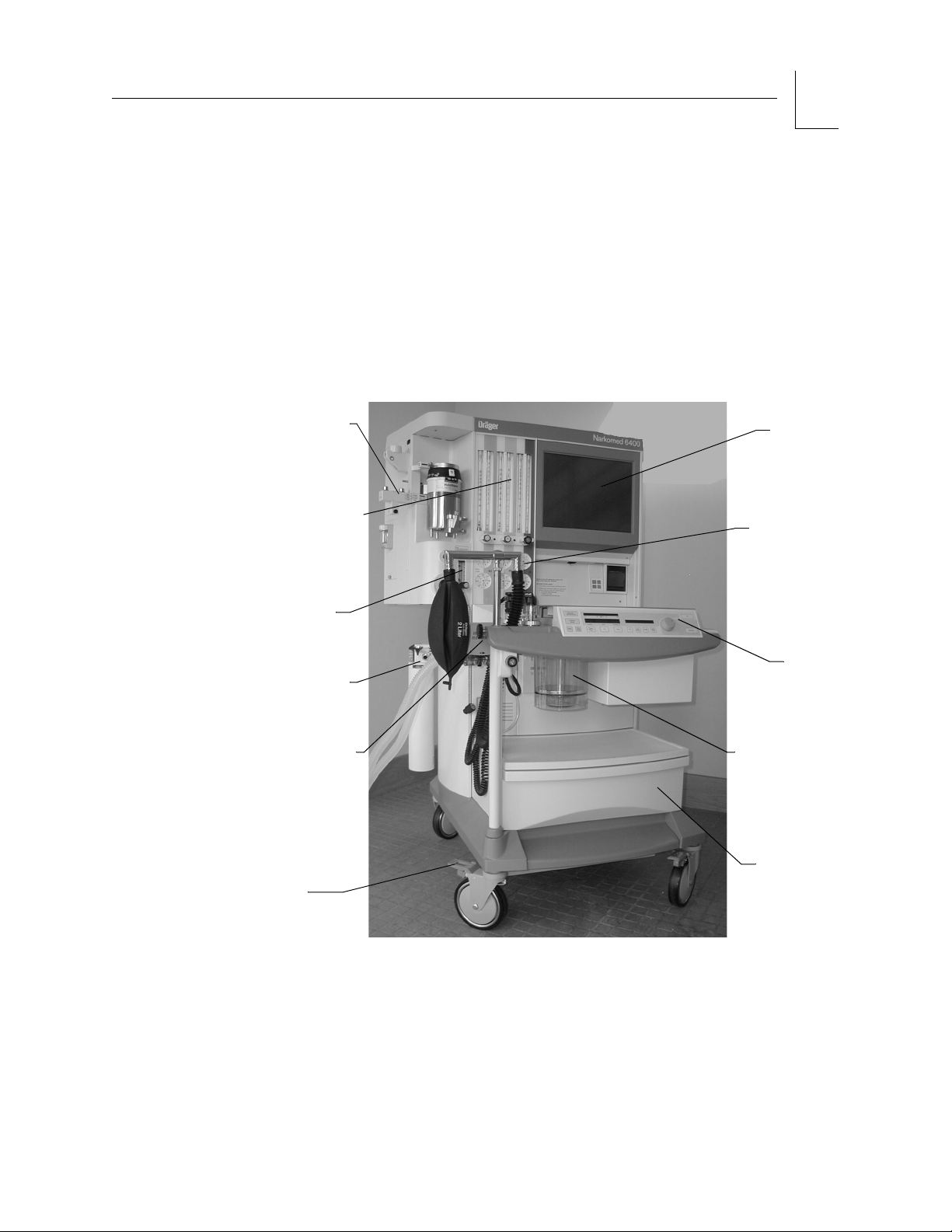
VAPORIZER
MOUNT
FLOWMETERS
SYSTEM
DISPLAY
MONITOR
PRESSURE
GAUGES
2
AUXILIARY
O2
FLOWMETER
SCAVENGER
(OPTIONAL)
ULTRASONIC
FLOW
SENSOR
BRAKE
Figure 2-1. Narkomed 6400 Anesthesia Workstation
Narkomed 6400 operating system components include:
• gas delivery system
• vaporizer mount and interlock system
DIVAN
VENTILATOR
ABSORBENT
CANISTER
STORAGE
DRAWER
• Divan ventilator
• Narkomed ultrasonic flow sensor
Part Number: 4117965-003
Rev: -
Narkomed 6400 Operator’s Manual
2-3
Page 22

2
System Description
RETURN TO THIS MANUAL'S TABLE OF CONTENTS
RETURN TO CD-ROM TABLE OF CONTENTS
• power supply system
• monitoring system
• measurement subsystems
• piping
• open reservoir scavenger or
system (CUSTOMER OPTION)
• strip chart recorder (SCR) (CUSTOMER OPTION)
• patient suction system (CUSTOMER OPTION)
• auxiliary video output (CUSTOMER OPTION)
• surgeon display controller (CUSTOMER OPTION)
• sheet printer interface (CUSTOMER OPTION)
A brief description of the capabilities of each system component follows.
Please see Sections 7 and 8 of this manual for details on Narkomed 6400
operation.
The Narkomed 6400 incorporates three interfaces: a gas delivery interface
in a cockpit-style design, a configurable monitoring interface accessed
through a touch screen, and a ventilator interface for adjustment/display of
programmed parameters.
Gas Delivery System
The Narkomed 6400 can simultaneously deliver up to three gases and one
anesthetic agent. Three pipeline gas inlets connect to central gas delivery
systems, and three yokes connect to cylinder gas supplies.
interface for passive scavenger
2-4
Each gas supply has separate controls and flowmeter indicators. Individual
pressure gauges provide pressure readings. All connectors, valves, gauges,
and flowmeters are labeled and color-coded for the appropriate gas as shown
in the following table.
Gas System Color Coding
Gas Marking USA ISO
Air AIR Yellow Black/White
Checkered
Nitrous Oxide N
Oxygen O
Narkomed 6400 Operator’s Manual
OBlueBlue
2
2
Green White
Part Number: 4117965-003
Rev: -
Page 23
RETURN TO THIS MANUAL'S TABLE OF CONTENTS
RETURN TO CD-ROM TABLE OF CONTENTS
OP00669
O2
CYLINDER
YOKE
AIR
CYLINDER
YOKE
N2O
CYLINDER
YOKE
System Description
CONNECTION
CONNECTION
CONNECTION
2
O2
PIPELINE
AIR
PIPELINE
N20
PIPELINE
Pipeline Gas
Supply to the
Narkomed
6400
Cylinder Gas
Supply
Figure 2-2. Gas Delivery System Connections
The Narkomed 6400 features a controlled gas hookup that reduces the risk
of delivering the wrong gas to a patient. Pipeline gas inlets are indexed for
air, nitrous oxide, and oxygen fittings to be keyed to corresponding outlets of
hospital pipeline gases. The risk of incorrect connection of gas hoses is
thereby minimized. Pipeline gases should be supplied at 50 to 55 psi.
The system design also protects the patient, clinician, and its own systems
from contamination. Each pipeline gas inlet has a check valve that prevents
backflow leakage into the atmosphere when supply hoses are not connected.
Check valves also prevent pipeline flow into the internal gas lines of the
Narkomed 6400 when reserve cylinders are used. In addition, filters in each
pipeline connection prevent foreign material from entering the
Narkomed 6400.
When centrally-supplied gases are not used, the system runs on cylindersupplied gases. The Narkomed 6400 has a standard cylinder yoke
configuration of one yoke for each gas: oxygen, air, and nitrous oxide.
(Field-upgraded machines may have a different yoke configuration).
The controlled gas hookup for cylinders reduces the risk of delivering the
wrong gas to a patient. The cylinder yokes are labeled, color-coded, and
keyed for cylinders containing particular gases. A pin-indexed safety system
prevents incorrect cylinders from being connected to the yoke.
Part Number: 4117965-003
Rev: -
Narkomed 6400 Operator’s Manual
2-5
Page 24
2
System Description
RETURN TO THIS MANUAL'S TABLE OF CONTENTS
RETURN TO CD-ROM TABLE OF CONTENTS
Narkomed 6400 design protects the patient, clinician, and its own systems
from contamination while operating on cylinder gas. A check valve in each
yoke prevents leakage of ambient air into the patient circuit if a cylinder is
not mounted on the yoke. The check valve also prevents movement of gas
from one cylinder to another when two cylinders of the same gas are
attached. In addition, filters in each yoke prevent foreign material from
entering the internal gas system of the Narkomed 6400. Further protection
from contamination is provided by a yoke plug, attached to the yoke.
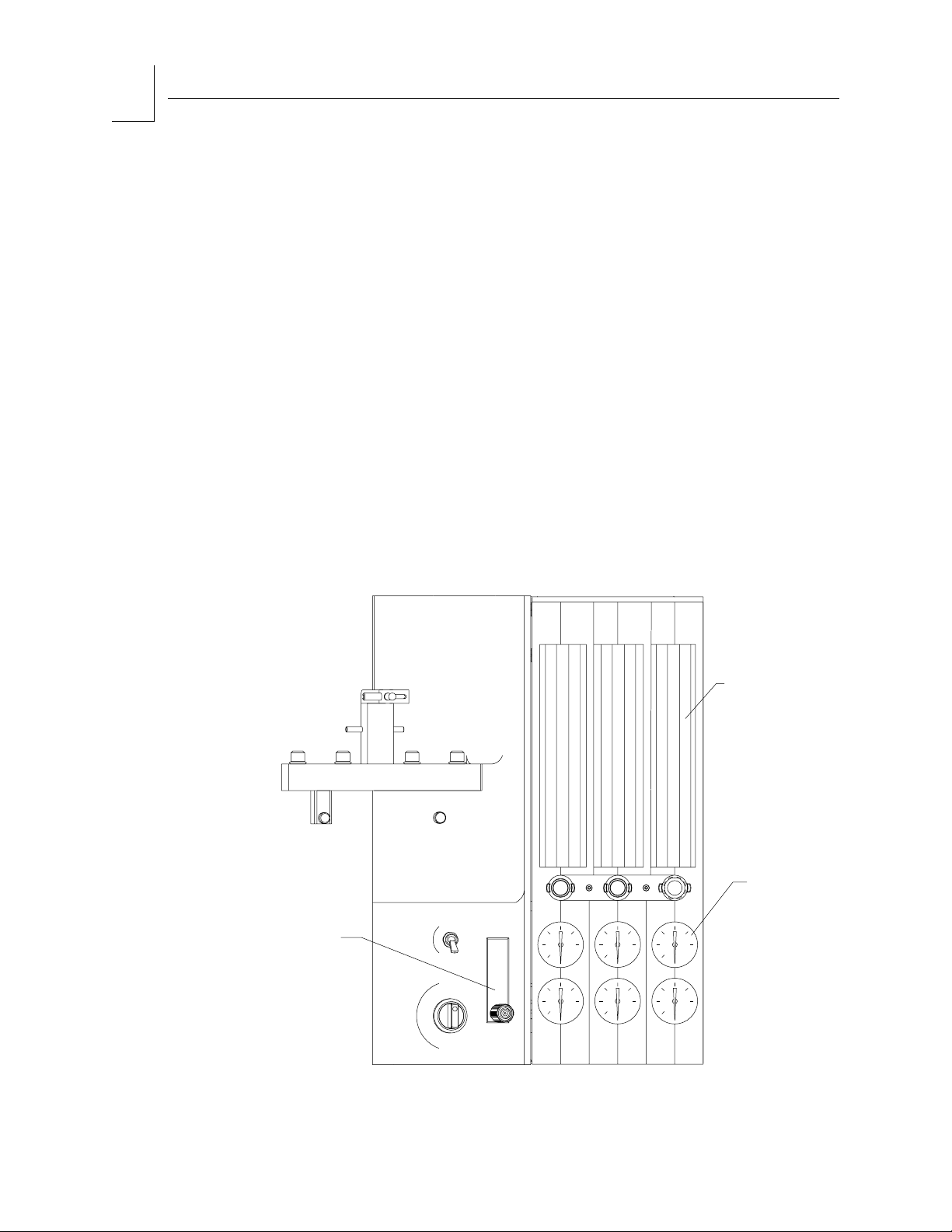
Flowmeter
Bank
Flowmeters
The Narkomed 6400 provides highly visible, easily scanned controls and
indicators for all gases flowing through its systems. The flowmeter bank
houses flowmeters, flow control valves, and pressure gauges for each gas.
There are separate pressure gauges for each gas source — one for each
pipeline gas supply and one for each cylinder gas supply.
The flowmeters are tapered tubes scaled in milliliters per minute (mL/min)
and liters per minute (L/min). Flowmeter scales are backlighted for ease of
observation. A float indicator shows the flow rate of each gas in the fresh
gas mixture as delivered to the Narkomed 6400. The flowmeters are labeled
and color-coded for gas identification.
FLOWMETERS
2-6
AUXILIARY
O2
FLOWMETER
OP00663
Figure 2-3. Flowmeter Bank
Narkomed 6400 Operator’s Manual
PRESSURE
Part Number: 4117965-003
GAUGE
Rev: -
Page 25

RETURN TO THIS MANUAL'S TABLE OF CONTENTS
RETURN TO CD-ROM TABLE OF CONTENTS
Flow Control
Valves
Pipeline
Pressure
Gauges
Cylinder
Pressure
Gauges
System Description
2
Adjustment knobs for the control valves that regulate gas flow are located
below their respective flowmeter tubes. They are labeled and color-coded for
gas lines containing particular gases. The oxygen flow control valve is also
touch-coded with a deeply fluted knob (bezel). Turning the valve adjustment
knob counterclockwise increases gas flow. Turning the knob clockwise
decreases flow. A knob guard prevents accidental adjustments to the gas
flow. A zero-stop prevents damage to the flow control valve seat.
Pipeline pressure gauges are located below their corresponding flow control
valves. The flowmeter panel is labeled and color-coded for pipelines
containing particular gases. Concentric scales in psi and kPa indicate the
pipeline supply pressure.
Below their corresponding pipeline pressure gauges, the cylinder pressure
gauges show remaining cylinder pressure. The flowmeter panel is labeled
and color-coded for cylinder lines containing particular gases. Concentric
scales in psi and kPa indicate the cylinder gas pressure when the cylinder
valve is open.
Electronic
Fresh Gas
Measurement
For nonliquified gases like oxygen and air, the pressure indicates the
proportion of gas in the cylinder. For a liquefied gas like nitrous oxide, the
gauge indicates the vapor pressure of the liquefied gas in the cylinder. This
pressure remains constant until all of the liquid in the cylinder is vaporized.
When the liquid is vaporized, the cylinder pressure decreases proportionally
as gas is removed from the cylinder.
In addition to the flowmeters, the Narkomed 6400 has an electronic flow
measurement system which can display current flow readings for air,
oxygen, and nitrous oxide on the Narkomed 6400 monitor screen. It also has
the capability to export the data via Vitalink to an information management
system. See “Fresh Gas Information” on page 3-45 of this manual for more
information.
Part Number: 4117965-003
Rev: -
Narkomed 6400 Operator’s Manual
2-7
Page 26
2
System Description
RETURN TO THIS MANUAL'S TABLE OF CONTENTS
RETURN TO CD-ROM TABLE OF CONTENTS
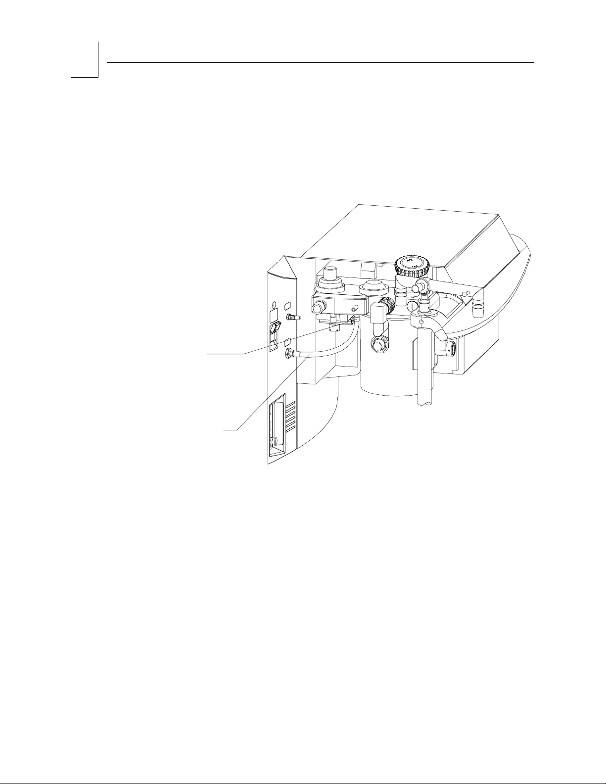
Fresh Gas
Outlet
The fresh gas outlet delivers the fresh gas mixture consisting of the gases
selected and the vapors of a liquid anesthetic agent to the patient breathing
system. It is located below the ventilator on the left front of the machine.
The quick connect fitting used is unique to the Narkomed 6400 and cannot
be replaced by a hose from any other make or model of anesthesia
machine.
UNIQUE
QUICK-CONNECT
FITTING
FRESH GAS
HOSE
Figure 2-4. Fresh Gas Outlet with Quick-Connect Fitting
OP00673
2-8
Narkomed 6400 Operator’s Manual
Part Number: 4117965-003
Rev: -
Page 27
RETURN TO THIS MANUAL'S TABLE OF CONTENTS
RETURN TO CD-ROM TABLE OF CONTENTS
Oxygen Gas Supply Special Features
Auxiliary
Oxygen
Flowmeter
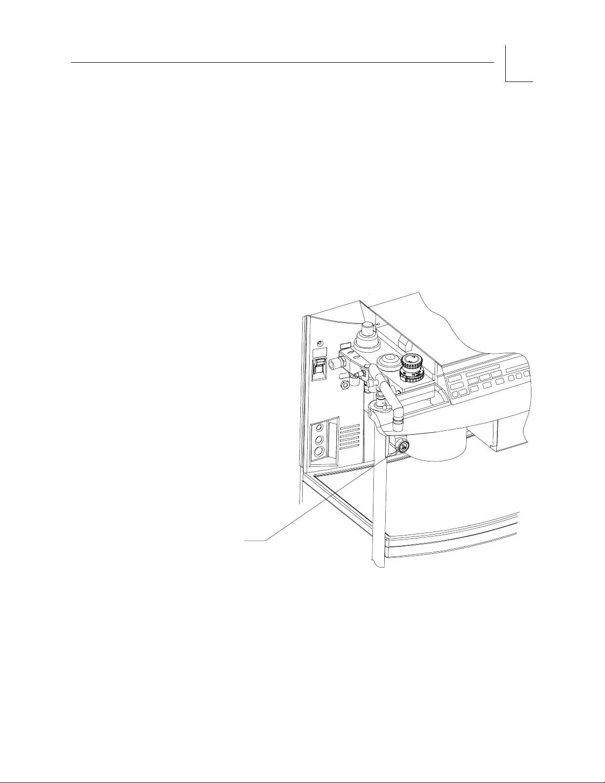
Oxygen
Flush
The auxiliary oxygen flowmeter (see Figure 2-3) delivers a metered flow of
pure oxygen, used, for example, in the delivery of oxygen through a nasal
cannula. Auxiliary oxygen can also be used when the system power switch is
in the STANDBY position.
A manually operated, self-closing, oxygen flush valve is located on the front
left corner of the Narkomed 6400. A bezel is mounted around the
pushbutton to prevent accidental engagement. When actuated, the valve
delivers an unmetered oxygen flow of about 55 L/min directly to the fresh
gas common outlet. The power switch does not have to be on to use the
oxygen flush; it remains operative in STANDBY position.
OP00674
System Description
2
OXYGEN FLUSH
BUTTON
Figure 2-5. Oxygen Flush Button
Part Number: 4117965-003
Rev: -
Narkomed 6400 Operator’s Manual
2-9
Page 28

2
System Description
RETURN TO THIS MANUAL'S TABLE OF CONTENTS
RETURN TO CD-ROM TABLE OF CONTENTS
Oxygen
Supply
Pressure
Failure
Protection
Device
Oxygen Low
Pressure
Alarm
Minimum
Oxygen Flow
The oxygen failure protection device (OFPD) is a pneumatically operated
valve that protects the patient in the event of partial or complete loss of
oxygen pressure. Each gas circuit in the anesthesia machine, except the
oxygen circuit, is controlled by one of these valves. These valves, in turn, are
controlled by the gas pressure in the oxygen supply line. When oxygen
pressure is adequate, the valves remain open for an unrestricted gas flow.
Loss of oxygen pressure causes the valves to close to a degree that is
proportional to the loss. The result is a restriction or shut down of the flow
of all gases except oxygen.
Gas flow reductions are indicated on the flowmeter. When the oxygen
supply from the pipeline or reserve cylinders drops below about 37 psi, a
O2 SUPPLY LOW alarm is activated and, depending on the machine’s
configuration, a 7-second whistle may also sound. However, if only one
source of oxygen supply pressure (either reserve cylinders or pipeline) fails
and the other source maintains proper supply pressure, the OFPD and
oxygen supply low alarm are not activated.
The Narkomed 6400 has an oxygen dispensing system with a calibrated
bypass flow of 150 ±50 mL/min at 50 psi pipeline pressure. This volume of
oxygen is delivered even if the oxygen flow control valve should become fully
closed.
Note: Minimum oxygen flow is disabled in the optional Air-Only Mode. For
more information, see the Operator’s Manual for Air-Only Mode for
the Narkomed 6400 Anesthesia System.
Oxygen Ratio
Controller
The ratio of oxygen to nitrous oxide is controlled by another interlock
system. The oxygen ratio controller (ORC) is designed to maintain a
minimum fresh gas oxygen concentration of 25±4%. It provides independent
control of the oxygen and nitrous oxide flows pneumatically.
The ORC works by proportionally limiting the nitrous oxide flow whenever
the selected oxygen and nitrous oxide flow control valve settings would
otherwise result in a hypoxic fresh gas mixture. For example, if the clinician
opens the nitrous oxide flow control valve wide open without making a
corresponding increase in the oxygen flow control valve setting, the nitrous
oxide flow will not increase. Similarly, if the clinician decreases the oxygen
flow without also decreasing the nitrous oxide flow, the nitrous oxide flow
automatically drops in proportion to the oxygen flow.
2-10
Narkomed 6400 Operator’s Manual
Part Number: 4117965-003
Rev: -
Page 29
RETURN TO THIS MANUAL'S TABLE OF CONTENTS
RETURN TO CD-ROM TABLE OF CONTENTS
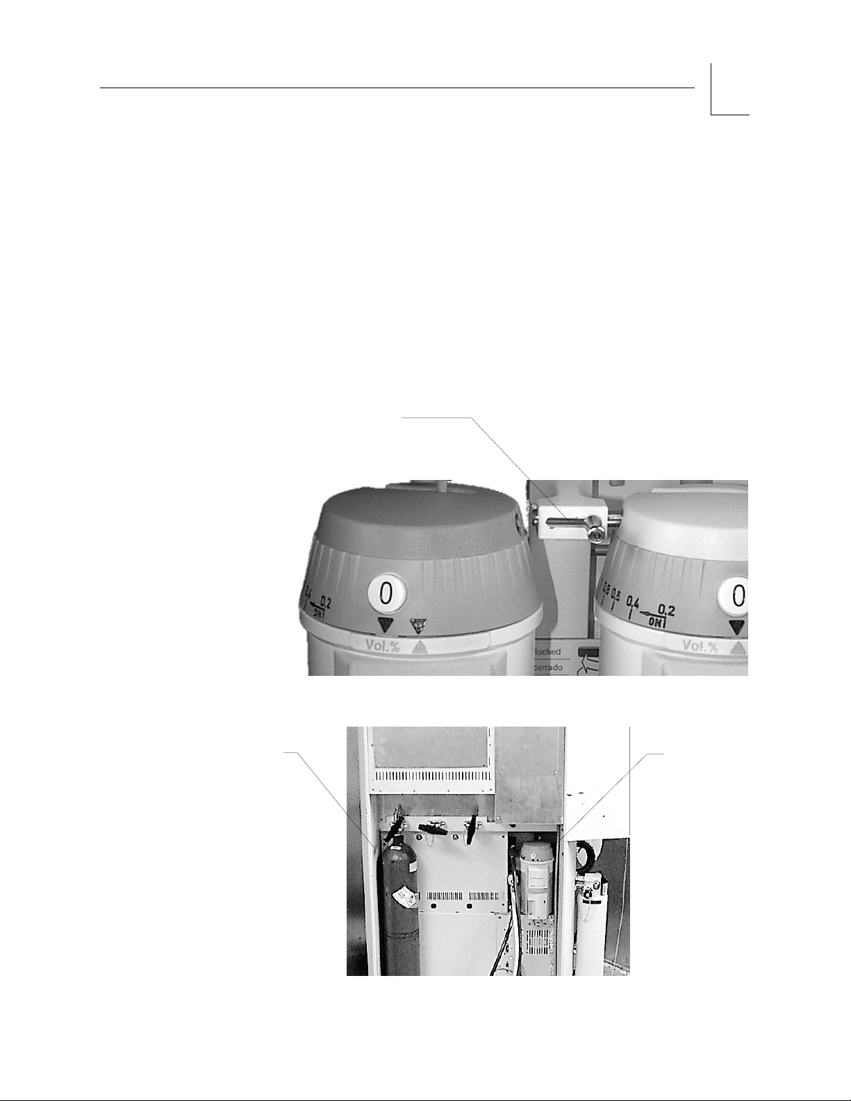
Vaporizer Mounts and Interlock Systems
The Narkomed 6400 provides mounts and an interlock system for either two
vaporizers (standard) or three vaporizers (customer option). With either
configuration, a mounting rack for a spare vaporizer is provided on the back
of the machine as shown in Figure 2-7.
Two
Vaporizer
Mount and
Interlock
System
The two vaporizers are mounted on the left front of the machine and both
are connected to the fresh gas flow. The interlock system allows the clinician
to select which vaporizer can be turned on, which prevents the two
vaporizers from being used simultaneously. To enable the left vaporizer, the
selector lever is moved to the right to lock out the right vaporizer. To enable
the right vaporizer, the selector lever is moved to the left to lock out the left
vaporizer.
VAPORIZER INTERLOCK
System Description
2
OP000179P
Figure 2-6. Two Vaporizer Interlock System
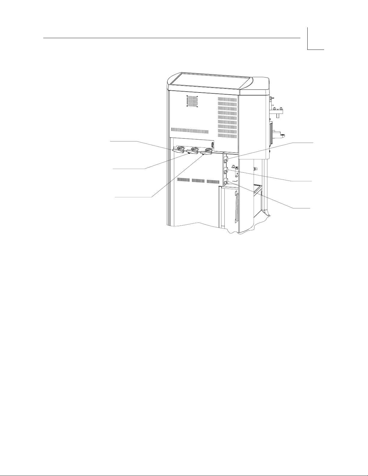
SERIAL
NUMBER
LABEL
Figure 2-7. Narkomed 6400 Rear View
Part Number: 4117965-003
Rev: -
Narkomed 6400 Operator’s Manual
MOUNTING
RACK FOR
SPARE
VAPORIZER
2-11
Page 30
2
System Description
RETURN TO THIS MANUAL'S TABLE OF CONTENTS
RETURN TO CD-ROM TABLE OF CONTENTS
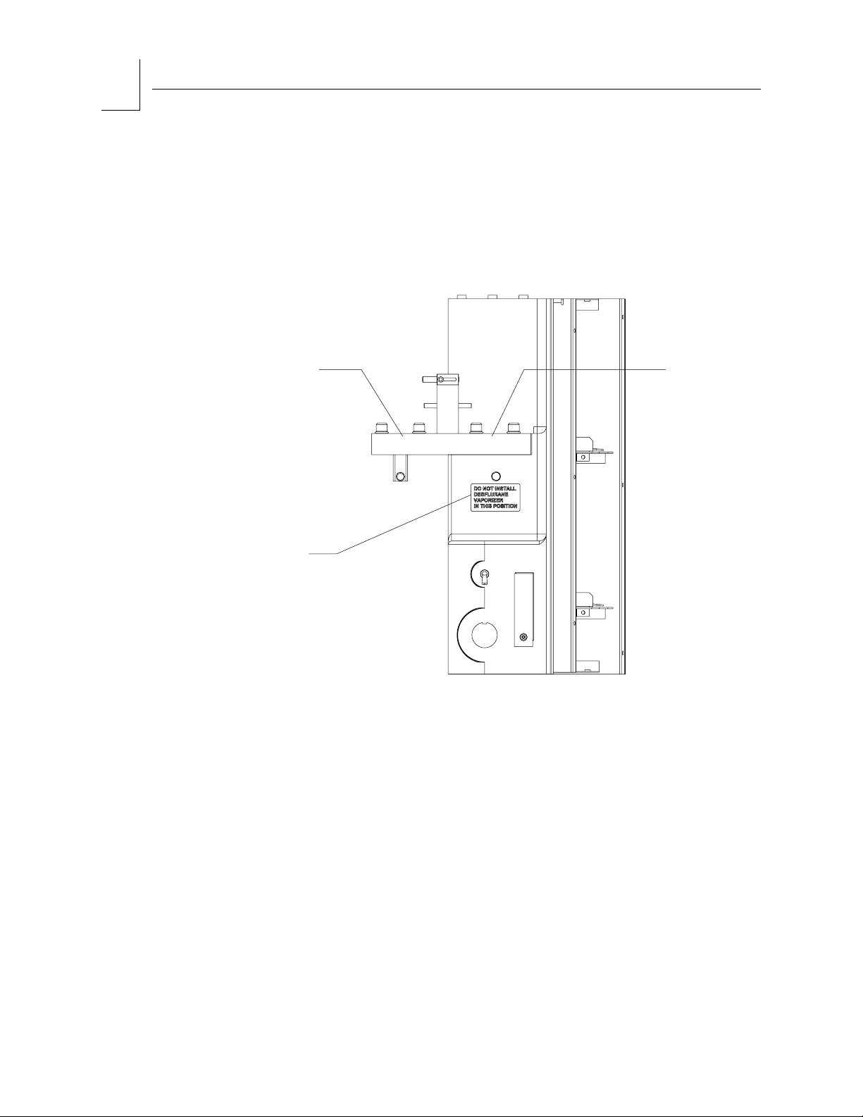
Warning : On machines equipped with the two vaporizer mount and
interlock system, the D-tec desflurane vaporizer must be
installed in the left-hand position. Installing the D-tec
desflurane vaporizer in the right-hand position can lead to
fresh gas and vapor leaks.
LEFT-HAND
VAPORIZER
POSITION
RIGHT-HAND
VAPORIZER
POSITION
WARNING
LABEL
Figure 2-8. Desflurane Warning Label (Two Vaporizer Mount and Interlock System)
OP00643
2-12
Narkomed 6400 Operator’s Manual
Part Number: 4117965-003
Rev: -
Page 31

RETURN TO THIS MANUAL'S TABLE OF CONTENTS
RETURN TO CD-ROM TABLE OF CONTENTS
Three
Vaporizer
Mount and
Interlock
System
(Customer
Option)
System Description
2
With the three vaporizer option, two of the vaporizers are mounted on the
left front of the machine and the third vaporizer is mounted on the left side
of the machine, above the other two vaporizers. All three vaporizers are
connected to the fresh gas flow. The interlock system allows the clinician to
select which vaporizer can be turned on and prevents more than one
vaporizer from being used at the same time. To enable the third (top)
vaporizer, move the selector lever completely up; this locks out the two
bottom vaporizers.
VAPORIZER
INTERLOCK
Figure 2-9. Three Vaporizer Interlock System
Part Number: 4117965-003
Rev: -
Narkomed 6400 Operator’s Manual
2-13
Page 32

2
System Description
RETURN TO THIS MANUAL'S TABLE OF CONTENTS
RETURN TO CD-ROM TABLE OF CONTENTS
Warning : On machines equipped with the three vaporizer mount and
interlock system, the D-tec desflurane vaporizer must be
installed in the upper mounting position. Do not install the
D-tec desflurane vaporizer in the lower mounting positions.
UPPER
MOUNTING
POSITION
RIGHT-HAND
LEFT-HAND
VAPORIZER
VAPORIZER
POSITION
WARNING
LABELS
Figure 2-10. Desflurane Labels (Three Vaporizer Mount and Interlock System)
POSITION
OP00700
2-14
Narkomed 6400 Operator’s Manual
Part Number: 4117965-003
Rev: -
Page 33

Y
RETURN TO THIS MANUAL'S TABLE OF CONTENTS
RETURN TO CD-ROM TABLE OF CONTENTS
System Description
2
Ventilator
Overview The Divan ventilator is an advanced electronic anesthesia ventilator. It has
an integrated compact breathing system and absorber. The operator control
panel is easily accessible.
BAG MOUNT ARM
PISTON
ASSEMBL
OPERATOR
CONTROL PANEL
Figure 2-11. Major Components of Ventilator
Using a circle system, the ventilator supports mechanical and manual
ventilation as well as spontaneous breathing. Ventilator operation may be a
semi-closed to virtually closed system with low flow and minimal flow
techniques.
The clinician may select Manual/Spontaneous Mode on the ventilator to
support spontaneous breathing by the patient or manual ventilation by the
clinician.
Under other conditions the clinician may select the specific mechanical
ventilation parameters for the case. The ventilator supports three
mechanical modes of ventilation:
• Volume Mode (time cycled and volume-controlled)
• Pressure Mode (time-cycled and pressure-controlled)
• Synchronized Intermittent Mandatory Ventilation (SIMV) Mode
(synchronized, time-cycled, and volume-controlled).
Part Number: 4117965-003
Rev: -
Narkomed 6400 Operator’s Manual
2-15
Page 34

2
System Description
RETURN TO THIS MANUAL'S TABLE OF CONTENTS
RETURN TO CD-ROM TABLE OF CONTENTS
The ventilator can control breathing patterns based on the following
electronic settings:
•airway pressure
•tidal volume
•rate
• I:E ratio
• inspiratory pause
• PEEP.
The ventilator makes automatic adjustments to ensure that preset tidal
volumes are delivered to the patient, regardless of the following conditions:
• patient compliance changes
• fresh gas flow changes
• compliance losses in the breathing system, absorber, and
breathing hoses.
The ventilator is designed with special features that enhance performance
while minimizing the cost of inhalation anesthesia delivery.
The ventilator is intended for use as an integrated part of the
Narkomed 6400. It is suitable for adults, children, and neonates.
Integration of the SIMV Mode facilitates weaning of the patient from
mechanical ventilation. See “SIMV Mode” on page 6-10 for discussion.
If the ventilator detects an internal fault which might affect patient safety
during mechanical ventilation, it initiates a safe state in which ventilation
can be continued, as in Manual/Spontaneous Mode. See “Ventilator Safe
State” on page 8-25 for details. A ventilator override switch is provided for
use in the unlikely event of an equipment fault which does not allow the
clinician to ventilate in normal Manual/Spontaneous Mode or safe state. See
“Ventilator Override” on page 8-26 for details.
2-16
Narkomed 6400 Operator’s Manual
Part Number: 4117965-003
Rev: -
Page 35

RETURN TO THIS MANUAL'S TABLE OF CONTENTS
RETURN TO CD-ROM TABLE OF CONTENTS
System Description
2
1
2
3
4
5
6
7 8
109
11
12
Legend
1 quick-release connection for airway
pressure measurement
2 inspiratory valve with mount for O
3 inspiration port 9 release lever and handle of piston
4 expiratory valve 10 piston assembly
5 expiration port with mount for flow sensor 11 absorber
6 adjustable pressure limiter (APL) valve 12 breathing bag hose connection
sensor 8 locking lever for breathing system and
2
7 handle of breathing system
piston assembly
assembly
6
Figure 2-12. Ventilator Component Details
Part Number: 4117965-003
Rev: -
Narkomed 6400 Operator’s Manual
2-17
Page 36

2
System Description
RETURN TO THIS MANUAL'S TABLE OF CONTENTS
RETURN TO CD-ROM TABLE OF CONTENTS
OP00670
INSPIRATORY
VALVE
INSPIRATORY
VALVE HOSE
CONNECTION
BAG HOSE
CONNECTION
EXPIRATORY
VALVE
APL VALVE
BAG
MOUNT
ABSORBENT
CANISTER
Y-PIECE
SENSOR HOSE CONNECTION
Figure 2-13. Compact Breathing System
RESPIRATORY FLOW
The flow of patient gas is directed by the compact breathing system, which
is fully described on page 21 of this section. The system includes:
• inspiratory and expiratory valves with patient hose
connectors
• pneumatic connectors
• absorber
• APL valve (pop-off valve)
• breathing bag with re-usable and sterilizable hose.
Gas control is provided by a mechanically driven piston assembly. Details
may be found on page 27 of this section.
2-18
Narkomed 6400 Operator’s Manual
Part Number: 4117965-003
Rev: -
Page 37

RETURN TO THIS MANUAL'S TABLE OF CONTENTS
RETURN TO CD-ROM TABLE OF CONTENTS
OP00017A
1
Manual/
Spontaneous
Volume
Mode
SIMV
Pres.
Mode
P
max.
P
set
V
T
Rate
I:E P EEP
2 3
Legend
1 Display Windows 4 Selector/Confirmation knob
2 Ventilation Mode Buttons 5 Standby Button
3 Parameter Setting Buttons 6 Test Button
Figure 2-14. Control Panel Functional Groups
The operator control panel provides:
• a bar graph display
• a numeric display
% I.P.
Flow
System Description
SIMV
Rate
4
2
6
Test
Standby
5
Respitone
(Customer
Option)
Power-Up
Diagnostic
Tests
• an alphanumeric display
• a selector/confirmation knob
• 13 functional buttons.
See “Ventilator Control Panel” on page 28 of this section for a full
description of this operator interface.
Respitone is a ventilation sound composed of two distinct tones. One tone
annunciates when the pressure waveform crosses the apnea threshold
(corresponding to inhalation), and another tone annunciates on the rising
edge of a valid CO
breath (corresponding to exhalation). The specific
2
Respitone sound is chosen in the Respitone page of the Ventilator
Information Notebook (see page 3-30).
Power is supplied to the ventilator when the system power switch on the
Narkomed 6400 is turned on. A self-diagnostic test is performed during
power-up to check the ventilator and breathing system status, including
leakage and system compliance. The self-diagnostic test results are
displayed on the operator control panel display. The clinician can bypass the
self-test in emergency situations.
A periodic leak check is automatically performed during ventilation. A
system leak and compliance test can be manually performed while in
Ventilator Standby status.
Part Number: 4117965-003
Rev: -
Narkomed 6400 Operator’s Manual
2-19
Page 38

2
System Description
RETURN TO THIS MANUAL'S TABLE OF CONTENTS
RETURN TO CD-ROM TABLE OF CONTENTS
Mechanical
Ventilation
Modes
Mechanical ventilation is available in three modes:
Mode Function
Volume Mode time-cycled ventilation which controls the tidal volume delivery during
inspiration
Pressure Mode time-cycled ventilation whereby the system controls the pressure
maintained during inspiration
SIMV Mode synchronizes volume-controlled mechanical breaths with the patient’s
own breathing efforts, while ensuring at least a minimum breath rate
During mechanical ventilation the adjustable pressure limiter (APL) valve
is isolated from the breathing system.
The ventilator has a Manual/Spontaneous Mode which bypasses mechanical
ventilation to deliver gas volume via a breathing bag or through the
patient’s spontaneous breaths.
The ventilator also has a Ventilator Standby mode to minimize drive gas
use and permit inspection or repairs when a patient is not being ventilated.
Warning : Assisted ventilation is not possible with the Ventilator in
Ventilator Standby mode.
Tidal Volume
Compensation
Fresh Gas
Decoupling
Due to the compliance of the breathing system, some gas displaced by the
piston will not be delivered to the patient. It remains in the hoses, absorber,
and breathing system of the ventilator. Depending on the ratio of lung
compliance and circuit compliance, this can result in a large deviation
between preset tidal volume and tidal volume delivered to the lung.
The tidal volume compensation feature measures the system compliance
and enables the preset tidal volume to be delivered to the patient’s lungs.
The ventilator makes automatic adjustments to ensure that preset tidal
volumes are delivered to the patient despite any of the following conditions:
• patient compliance changes
• fresh gas flow changes
• compression losses in the breathing system, absorber, and
breathing hoses.
During inspiration, breathing gas flows from the piston assembly to the
patient. Fresh gas is isolated from the patient circuit and accumulates in
the breathing bag. During expiration, the fresh gas flow and breathing bag
are connected to the patient circuit and mix with breathing gas as the piston
retracts and excess gas is discharged to the scavenger.
2-20
Narkomed 6400 Operator’s Manual
Part Number: 4117965-003
Rev: -
Page 39

RETURN TO THIS MANUAL'S TABLE OF CONTENTS
RETURN TO CD-ROM TABLE OF CONTENTS
Low-Flow
Technique
System Description
2
In traditional ventilators, which are not fresh gas decoupled, the delivered
tidal volume is the sum of the volume delivered from the ventilator and the
fresh gas volume. Fresh gas decoupling, a design feature of the Narkomed
6400, allows tidal volumes to be maintained by the ventilator, despite
changes in fresh gas flow.
Integration of ventilator components results in efficient use of anesthetic
gas and offers the choice to reduce fresh gas flow. The low-flow technique
has several advantages:
• lower anesthetic gas and agent consumption
• more effective humidification and heating of inspiratory gas
• lower environmental burden.
The Divan ventilator optimizes low-flow performance by minimizing
problems with excess moisture in the system. The breathing system and
piston assembly were designed to minimize compressible volume. A heater
has been incorporated into the design to minimize the condensation of
moisture when using the low-flow technique.
Leak
Detection
Compact
Breathing
System
By automatically checking for leaks in the breathing system and hoses, the
ventilator helps to ensure minimal airway leakage, particularly important
during low flow anesthesia.
The compact breathing system directs the flow of patient gas using
diaphragm valves automatically opened and closed by a control module. It
contains the remainder of the Narkomed 6400 pneumatic interfaces and a
re-usable absorbent canister. Figure 2-15 presents a simplified diagram of
the ventilator pneumatic component systems and their relationship with
each other. Figure 2-16 shows the location of the breathing system
components. Figure 2-17 shows the connections of the compact breathing
system to the patient hoses and to the Narkomed 6400.
The compact breathing system provides enhanced pediatric and low flow
performance by minimizing the potential for leaks from connections and
reducing total volume. The breathing system is also heated to prevent
condensation of moisture in the system and provide a warm, humidified gas
to the patient.
Part Number: 4117965-003
Rev: -
Narkomed 6400 Operator’s Manual
2-21
Page 40

2
System Description
RETURN TO THIS MANUAL'S TABLE OF CONTENTS
RETURN TO CD-ROM TABLE OF CONTENTS
Fresh gas
Breathing bag
Patient
Pressure Oxygen
Volume
PEEP
MAN/SPONT
toggle switch
(toggle style only)
Legend
Sensor
Pilot-operated diaphragm valve
Variable-resistance valve
Directional valve
Spring-loaded directional valve
Manually actuated two-way valve
Insp.
Exp.
Absorber
Piston pump
APL
OP00051
2-22
Figure 2-15. Simplified Schematic of Breathing System Pneumatic Subsystems
Narkomed 6400 Operator’s Manual
Part Number: 4117965-003
Rev: -
Page 41

RETURN TO THIS MANUAL'S TABLE OF CONTENTS
RETURN TO CD-ROM TABLE OF CONTENTS
System Description
2
EXPIRATORY VALVE APL VALVE
OXYGEN
SENSOR
INSPIRATORY
VALVE
RESPIRATORY
FLOW SENSOR
OP00671
ABSORBENT CANISTER
Figure 2-16. Compact Breathing System Components
PATIENT HOSE
CONNECTION
AIRWAY PRESSURE
MEASUREMENT
CONNECTION
SECONDARY
VACUUM RELIEF
VALVE
FRESH GAS
HOSE
CONNECTIONS
BAG HOSE
CONNECTIONS
BAG CONNECTION
OP00672
Figure 2-17. Compact Breathing System Connections
Part Number: 4117965-003
Rev: -
SCAVENGER
CONNECTION
Narkomed 6400 Operator’s Manual
PATIENT HOSE
CONNECTION
2-23
Page 42

2
System Description
RETURN TO THIS MANUAL'S TABLE OF CONTENTS
RETURN TO CD-ROM TABLE OF CONTENTS
Inspiratory
and Expiratory
Valves
Pneumatic
Connectors
Absorber
The ventilator has two 22 mm connectors for connecting standard
inspiratory and expiratory patient hoses to the ventilator. Other system
components, such as patient airway filters, may be mounted here.
The ventilator has fittings for fresh gas inlet, breathing bag, airway
pressure measurement, and exhaust of excess patient gas to the scavenger.
The absorber is a single canister system for absorbing exhaled carbon
dioxide in the rebreathing circuit. The re-usable absorber canister uses
loose, granular soda lime absorbent. Design of the Narkomed 6400 permits
easy access for inspection or service of the canister from the front of the
machine.
ABSORBER
CANISTER
APL Valve
2-24
Figure 2-18. Location of Absorber Canister on Ventilator
Note: Your Narkomed 6400 may be equipped with either the knob-style or
the toggle-style APL valve. Operational instructions are provided for
both style valves throughout the manual. However, with the
exception of Figure 2-20, all illustrations of the APL valve in this
manual show the knob-style APL valve to avoid duplication of
illustrations.
The APL valve, also known as the pop-off valve, has two functions. It limits
the maximum pressure during manual ventilation. It also exhausts excess
gas into the scavenger system during manual and spontaneous ventilation.
The APL valve is connected to the patient airway through the ventilator. It
functions only when the ventilator is in Manual/Spontaneous Mode, safe
state, or ventilator override condition.
Narkomed 6400 Operator’s Manual
Part Number: 4117965-003
Rev: -
Page 43

RETURN TO THIS MANUAL'S TABLE OF CONTENTS
RETURN TO CD-ROM TABLE OF CONTENTS
System Description
2
Knob-Style APL Valve
The knob-style APL valve has an adjustment knob used to select either
spontaneous or manual modes of ventilation. The adjustment knob is
labeled to indicate approximate pressure settings.
For spontaneous ventilation:
Pressure is released for spontaneous ventilation when the APL valve
adjustment knob is rotated fully counterclockwise to
Spont position (the
index mark on the knob will line up with the index mark on the bottom of
the APL valve). Spontaneous ventilation automatically eliminates
resistance to patient exhalation.
For manual ventilation:
In manual mode (Man position), the APL valve adjustment knob can be
rotated to change the approximate pressure at which gas will flow through
the valve and into the scavenging system. Clockwise rotation of the APL
valve knob increases the pressure, and counterclockwise rotation of the
APL valve knob decreases the pressure. Pulling up on the APL valve knob
will temporarily relieve pressure.
.
Figure 2-19. Ventilator APL Valve (Knob-Style)
APL VALVE
ADJUSTMENT
KNOB
INDEX
MARKS
Part Number: 4117965-003
Rev: -
Narkomed 6400 Operator’s Manual
2-25
Page 44

2
System Description
RETURN TO THIS MANUAL'S TABLE OF CONTENTS
RETURN TO CD-ROM TABLE OF CONTENTS
Toggle-Style APL Valve
The toggle-style APL valve has a toggle switch for selecting between manual
and spontaneous modes of ventilation. When the side of the switch marked
MAN is up, the APL valve sets maximum pressure for manual ventilation.
When the side marked SPONT
is up, pressure is released for spontaneous
ventilation. Depressing the switch while in the MAN position will also
temporarily relieve pressure.
Maximum pressure adjustment is made by rotating the APL valve
adjustment when the toggle switch is in the MAN position to set peak
airway pressure. The adjustment housing is labelled to indicate pressure
settings. Rotating the adjustment counterclockwise reduces the peak
inspiratory pressure and the pressure at which gas is released to the
scavenging system. Rotating the adjustment clockwise increases the peak
inspiratory pressure and the pressure at which gas is released to the
scavenging system.
During spontaneous ventilation resistance to patient exhalation is
automatically eliminated by toggling to the SPONT position, which
eliminates the need to re-adjust backpressure.
.
MAN/SPONT
TOGGLE SWITCH
APL VALVE
ADJUSTMENT
Figure 2-20. Ventilator APL Valve (Toggle-Style)
2-26
Narkomed 6400 Operator’s Manual
Part Number: 4117965-003
Rev: -
Page 45

RETURN TO THIS MANUAL'S TABLE OF CONTENTS
RETURN TO CD-ROM TABLE OF CONTENTS
Bag Mount
Arm
System Description
The bag mount arm rotates to facilitate ergonomic positioning of the
breathing bag in an efficient position. The height of the bag can also be
adjusted and locked in place by tightening the lock knob. For the
convenience of the clinician, a 15 mm plug is provided for occluding the
Y-piece, which is required during the self test or the leak and compliance
test.
15MM PLUG
2
Piston
Assembly
BAG LOOP
RETAINER
ADJUSTABLE
BAG MOUNT ARM
OP00675
Figure 2-21. Bag Mount Arm
The ventilator piston assembly is found by opening the ventilator top cover.
See “Ventilator Component Details” on page 17 of this section for a top view
of the piston assembly. It contains a mechanically driven piston that
controls the amount of gas delivered to the patient during mechanical
ventilation. The piston assembly delivers gas via an electrically-controlled
motor drive, as compared with the gas-driven bellows found in older types of
ventilators. This feature allows for more accurate control of tidal volume
delivery while minimizing compressible volume and waste of drive gas.
Mechanical integrity is maintained with rolling seal diaphragms.
Part Number: 4117965-003
Rev: -
Narkomed 6400 Operator’s Manual
2-27
Page 46

2
System Description
RETURN TO THIS MANUAL'S TABLE OF CONTENTS
RETURN TO CD-ROM TABLE OF CONTENTS
Ventilator
Control Panel
Display
Windows
Bar Graph
Display
Configuration and use of the ventilator is accomplished through the
operator control panel, located on the front of the ventilator. See “Control
Panel Functional Groups” on page 19 of this section for an overview. The
panel provides display windows and control buttons for selecting parameter
settings, ventilation modes, Ventilator Standby, and test operation.
Display windows inform the clinician about piston movement, current
ventilator settings, operator prompts, device status, and errors. The
ventilator does not display any measured patient parameters, which are
available on the Narkomed 6400 monitor screen.
The bar graph, located in the top left corner of the panel, is a indicator of
piston movement during inspiration and expiration. It displays a percent of
the value set for tidal volume. The 0% indication means full exhalation. The
100% indication means full inhalation. The indicator will not reach 100%
during inhalation if the ventilator has not reached the full preset tidal
volume setting.
BAR GRAPH DISPLAY
Manual/
Spontaneous
Test
Volume
Mode
SIMV
Pres.
Mode
P
max.
P
set
V
T
Rate
% I.P.
I:E
Flow
PEEP
SIMV
Rate
0% 100%
Figure 2-22. Location of Piston Movement Indicator (Bar Graph Display)
Standby
OP00018
2-28
Narkomed 6400 Operator’s Manual
Part Number: 4117965-003
Rev: -
Page 47

RETURN TO THIS MANUAL'S TABLE OF CONTENTS
RETURN TO CD-ROM TABLE OF CONTENTS
Numeric
Display
System Description
2
Three numeric displays, located just below the bar graph indicator, show
current settings for maximum allowable pressure (Pmax) or preset airway
pressure (Pset) in cmH
O, tidal volume in milliliters or liters (VT), and
2
breathing rate in breaths per minute (Rate). The numbers displayed
correspond with the settings for the parameter buttons located directly
below them.
Manual/
Spontaneous
Volume
SIMV
Mode
P
P
23
max.
set
Pres.
Mode
V
T
P
max.
P
set
V
T
Rate
12600
Breaths/min.mL[L]cm H2O
Rate
% I.P.
I:E PEEP
Flow
SIMV
Rate
OP00019
Test
Standby
NUMERIC DISPLAY
Figure 2-23. Location of Ventilator Pressure, Volume, and Rate Numeric Displays
Activation of numeric displays depend upon the ventilation mode selected
by the clinician:
• maximum allowable pressure (Pmax) will always be displayed in
Volume Mode or Synchronized Intermittent Mandatory
Ventilation (SIMV) Mode
• preset tidal volume (V
) will always be displayed in Volume
T
Mode or Synchronized Intermittent Mandatory Ventilation
(SIMV) Mode
• preset airway pressure (Pset) will always be displayed in
Pressure Mode
• breathing rate in breaths per minute (Rate) will always be
displayed in Pressure Mode or Volume Mode.
Part Number: 4117965-003
Rev: -
Narkomed 6400 Operator’s Manual
2-29
Page 48

2
System Description
RETURN TO THIS MANUAL'S TABLE OF CONTENTS
RETURN TO CD-ROM TABLE OF CONTENTS
Alphanumeric
Display
An alphanumeric display, capable of holding 16 characters, is located to the
right of the bar graph and numeric displays.
ALPHANUMERIC DISPLAY SELECTION/
CONFIRMATION
KNOB
Manual/
Spontaneous
Volume
SIMV
Mode
Pres.
Mode
CURRENT
P
max.
P
set
NEW
SETTING
SETTING
V
T
Rate
% I.P.
I:E PEEP
Flow
SIMV
Rate
INCREASE
Test
Standby
23 Pmax/cmH2O 23
OP00015
I:E
% I.P.
Flow
PEEP
SIMV
Rate
DECREASE
Selector/
Confirmation
Knob
Figure 2-24. Location of Ventilator Alphanumeric Display
The alphanumeric display provides the following types of messages:
• messages prompting the clinician to set appropriate conditions
and take specific actions during initial self-test and during
normal operation
• messages reporting status and faults
• messages prompting the clinician to confirm changes to
ventilator mode or parameter settings
• error messages, displayed in the event of an abnormal condition.
Rotating the selector/confirmation knob changes a parameter setting after
the parameter has been selected by pressing the appropriate button.
Rotating the knob clockwise increases the setting. Rotating the knob
counterclockwise decreases the setting.
Pressing the selector/confirmation knob confirms changes in mode or
parameter settings and confirms and/or clears prompts. After the clinician
presses the selector/confirmation knob, an audible tone is sounded (if
enabled) to acknowledge the change in settings.
2-30
Narkomed 6400 Operator’s Manual
Part Number: 4117965-003
Rev: -
Page 49

RETURN TO THIS MANUAL'S TABLE OF CONTENTS
RETURN TO CD-ROM TABLE OF CONTENTS
Ventilation
Mode Buttons
System Description
2
The clinician selects the type of ventilation control method by pressing a
ventilation mode button and then confirming the choice. Each button has an
indicator light that energizes when the mode is achieved. The light flashes
when the mode is selected. If the selector/confirmation knob is not pressed
within 10 seconds, the light is extinguished and the ventilator continues in
the previously selected mode.
Manual/
Spontaneous
Volume
Mode
SIMV
Pres.
Mode
P
max.
P
set
V
T
Rate
VENTILATION
MODE BUTTONS
Figure 2-25. Ventilator Mode Buttons
% I.P.
I:E
Flow
PEEP
SIMV
Rate
Test
Standby
OP00016A
Ventilation Mode Button Action When Confirmed
[Manual/Spontaneous]
bypasses mechanical ventilation to deliver gas volume via a
breathing bag or through the patient’s spontaneous breaths
[Volume Mode]
[SIMV]
sets time-cycled, volume-controlled mechanical ventilation
synchronizes mechanical ventilation with patient’s breathing
efforts through Synchronized Intermittent Mandatory
Ventilation (SIMV)
[Pres. Mode]
sets time-cycled, pressure-controlled mechanical ventilation
Part Number: 4117965-003
Rev: -
Narkomed 6400 Operator’s Manual
2-31
Page 50

2
System Description
RETURN TO THIS MANUAL'S TABLE OF CONTENTS
RETURN TO CD-ROM TABLE OF CONTENTS
Parameter
Setting
Buttons
Parameter setting buttons are used with the alphanumeric display and
selector/confirmation knob to change operating parameters for the
ventilator.
Pressing the button once sends the current setting to the alphanumeric
display. Rotating the selector/confirmation knob changes the displayed
setting.
Manual/
Spontaneous
Volume
Mode
P
Pres.
SIMV
Mode
Figure 2-26. Ventilator Parameter Setting Buttons
Parameter
Setting Button
[Pmax/Pset]
max.
P
set
V
T
Rate
% I.P.
I:E
Flow
PEEP
SIMV
Rate
PARAMETER SETTING BUTTONS
Action When Confirmed
sets the maximum allowable breathing pressure in Volume and SIMV
Modes; sets the airway control pressure for Pressure Mode
Standby
OP00016
Test
Ventilator
Standby
Button
Tes t B u tt o n
[Vt]
[Rate]
sets the control tidal volume in Volume and SIMV Modes
sets ventilation frequency as breaths per minute in Volume and Pressure
Modes
[I:E]
sets the ratio of inspiratory to expiratory time in Volume, Pressure, and
SIMV Modes
[% I.P/Flow] sets the ratio of inspiratory pause time to inspiration time in Volume and
SIMV Modes; sets the inspiratory flow rate in Pressure Mode
[PEEP]
[SIMV Rate]
sets the positive end-expiratory pressure in Volume and Pressure Modes
sets minimum ventilation frequency in SIMV Mode
Pressing the [Standby] button and confirming the choice sets the ventilator
to Ventilator Standby, which minimizes drive gas use and allows for
inspection or repairs when a patient is not being ventilated.
Pressing the [Test] button initiates a ventilator test to measure system
compliance and leakage. This test can only be initiated when the ventilator
is in Ventilator Standby status. The Y-piece must be occluded to
successfully complete the test. Fresh gas flow should be adjusted to
minimum.
2-32
Narkomed 6400 Operator’s Manual
Part Number: 4117965-003
Rev: -
Page 51

RETURN TO THIS MANUAL'S TABLE OF CONTENTS
RETURN TO CD-ROM TABLE OF CONTENTS
Ultrasonic
Flow Sensor
System Description
2
An ultrasonic flow sensor measures respiratory flow rate. The velocity and
flow rate of gas through the patient circuit are determined by measuring the
differential time of flight of ultrasonic pulses transmitted upstream and
downstream in the airway flow path. Flow measurements are independent
of gas concentration and yield precise values with all normal anesthetic
gases except Heliox.
The following figure illustrates the flow sensor assembly installed in the
Narkomed 6400. The flow sensor housing connects to the patient circuit at
the expiratory valve fitting. Two transducers (sensors) sense the differential
time of flight. The electronics assembly controls the transducers, processes
the data, and provides output to the Narkomed 6400 through a sensor cable
that connects through the breathing system interface panel. A lever secures
and releases the electronics assembly from the flow housing and
transducers.
EXPIRATORY
VALVE
ELECTRONICS
HOUSING
OP00676
22MM HOSE
TO Y-PIECE
FLOW
SENSOR
CONNECTION
Figure 2-27. Narkomed Ultrasonic Flow Sensor
FLOW HOUSING/
TRANSDUCER
ASSEMBLY
SENSOR CABLE
Flow sensor output is used by the Narkomed 6400 processor to calculate and
display numeric values for tidal volume, minute volume, and rate, as well as
the respiratory volume waveform display.
When the system power switch on the Narkomed 6400 is turned on, power
is supplied to the flow sensor. On power-up, the flow sensor performs a
self-diagnostic test.
Part Number: 4117965-003
Rev: -
Narkomed 6400 Operator’s Manual
2-33
Page 52

2
System Description
RETURN TO THIS MANUAL'S TABLE OF CONTENTS
RETURN TO CD-ROM TABLE OF CONTENTS
Breathing
System
Pressure
Gauge
(CUSTOMER
OPTION)
The Narkomed 6400 can be equipped with a mechanical pressure gauge to
enable quick visual determination of breathing circuit pressure. The gauge
is marked for measurements from -20 to +80 cm H
H
O. This gauge is an option that is available in addition to the standard
2
O in increments of 2 cm
2
software pressure gauge that can be displayed on the Narkomed 6400
screen.
The gauge is mounted on the side of the anesthesia machine and connects to
the breathing system interface panel.
Warning : To prevent leaks, make sure that the T-fitting joining the
breathing pressure pilot line and the pressure gauge hose is
securely connected to the breathing system interface panel.
OP00677
PRESSURE
GAUGE
PRESSURE
GAUGE HOSE
BREATHING
PRESSURE
PILOT LINE
T-FITTING
Figure 2-28. Breathing System Pressure Gauge and Connections
2-34
Narkomed 6400 Operator’s Manual
Part Number: 4117965-003
Rev: -
Page 53

V
RETURN TO THIS MANUAL'S TABLE OF CONTENTS
RETURN TO CD-ROM TABLE OF CONTENTS
Scavenger Systems (CUSTOMER OPTION)
The Narkomed 6400 can be equipped with one of two kinds of scavenger
systems for the best match with the facility’s waste gas disposal system.
Open
Reservoir
Scavenger
The open reservoir scavenger is used with suction (vacuum) waste gas
disposal systems. This scavenger is an “open” system with continually open
relief ports for positive and negative pressure control. The scavenger
flowmeter is easily examined during operation.
ACUUM
DISS HOSE
TERMINAL
System Description
LOCK NUT
VALVE KNOB
2
NEEDLE
THREADED
INPUT
PORT CAP
19MM
SCAVENGER
HOSE TERMINAL
RELIEF
PORT
OP75121
Figure 2-29. Open Reservoir Scavenger
SCAVENGER
HOSE TERMINAL
FLOWMETER
RESERVOIR
19MM
CANISTER
Part Number: 4117965-003
Rev: -
Narkomed 6400 Operator’s Manual
2-35
Page 54

2
System Description
RETURN TO THIS MANUAL'S TABLE OF CONTENTS
RETURN TO CD-ROM TABLE OF CONTENTS
Scavenger
Interface for
Passive
Systems
The scavenger interface for a passive system is used only with
nonrecirculating ventilation (exhaust) systems. This scavenger is a “closed”
system with a spring-loaded valve for positive pressure relief. It is not
meant to be used with suction disposal systems.
SAFETY RELIEF
VALVE, SHOWN
CLOSED
WASTE GAS
INPUT P ORT,
19MM HOSE
TERMINAL
WASTE GAS
INPUT P ORT,
19MM HOSE
TERMINAL
INPUT
PORT CAP
OP76131
Figure 2-30. Scavenger Interface for a Passive System
WASTE GAS EXH AUST PORT,
19MM HOSE TERMINAL
2-36
Narkomed 6400 Operator’s Manual
Part Number: 4117965-003
Rev: -
Page 55

RETURN TO THIS MANUAL'S TABLE OF CONTENTS
RETURN TO CD-ROM TABLE OF CONTENTS
Power Supply System
The Narkomed 6400 has a central power supply for the ventilator, alarm
system, and monitoring system. This design permits operation with only
one AC power cord, a safety feature. No subsystem, including the monitor,
has a separate ON/OFF switch. The following block diagram illustrates
both the power supply and feedback from the monitoring systems.
VENTILATOR
VPO MONITOR
MONITOR
GAS ANALYSIS
SPEAKERS
OP00001P
CENTRAL
PROCESSING
UNIT
POWER SUPPLY
(distributed)
System Description
SERVICE & TEST
CIRCUITS
STANDBY
SYSTEM
POWER
SWITCH
2
ON
System
Power Switch
Figure 2-31. Power Supply and Feedback from Monitoring Systems
The system power switch has two positions — ON and STANDBY. The
following table provides a summary of system components and functions
activated by the ON and STANDBY positions. When the power switch is in
the STANDBY position, this manual also refers to operating status as
System Standby.
Electrical / Pneumatic Circuit
convenience outlet energized energized
Narkomed 6400 warm-up energized energized
flush energized energized
O
2
auxiliary O
battery charging circuit energized energized
reserve power system energized energized
ventilator gas and electric power circuits energized OFF
ventilator control panel energized OFF
2
Power Switch in
ON Position
energized energized
Power Switch in
STANDBY Position
Narkomed 6400 monitor energized OFF
alarms energized OFF
Part Number: 4117965-003
Rev: -
Narkomed 6400 Operator’s Manual
2-37
Page 56

2
System Description
RETURN TO THIS MANUAL'S TABLE OF CONTENTS
RETURN TO CD-ROM TABLE OF CONTENTS
Convenience
Outlet
Circuit
Breakers
Electrical / Pneumatic Circuit
manual ventilation during primary and
reserve power failure
gas supplies (except oxygen) energized OFF
Power Switch in
ON Position
energized OFF
Power Switch in
STANDBY Position
The Narkomed 6400 has one convenience outlet, located on the rear of the
machine. The outlet is active when the Narkomed 6400 is plugged into an
outlet, whether or not the system power switch is turned on. A circuit
breaker protects the outlet. The total current for any device plugged into the
outlet must not exceed 2.5 amps.
The electrical system includes three circuit breakers to protect machine
functions. The circuit breakers are located at the bottom rear of the
machine. The three breakers are labeled as follows:
• AC main
• batteries
• convenience outlet.
When the plunger is flush with the surface of its base, the circuit breaker is
in its normal, closed position. A circuit breaker is open (tripped) when its
plunger extends beyond its base. If a breaker is tripped, the cause must be
found and corrected before using the Narkomed 6400.
Reserve
Power
System
The reserve power system consists of rechargeable batteries and a built-in
battery charging system, along with the interlock system that activates it
during primary power loss. At least 30 minutes of reserve power is
available.
Although most hospitals have emergency generators that provide AC power
when line power fails, a delay may occur before generator power comes
online. The reserve power system automatically provides power during the
period between line power failure and activation of the hospital’s emergency
generator. It also provides power if the power cord is accidentally unplugged
during a case.
When the hospital’s emergency generator comes online (or when a
disconnected power cord is reconnected), the Narkomed 6400 automatically
switches back to AC power and recharges its battery. The battery charging
system charges the battery any time the power cord is connected to an
active AC power source. The charger can recharge a fully discharged battery
in about 12 hours.
If the battery is not fully charged, a
BATTERY LOW alarm will be displayed.
This alarm means that there are about 10 minutes of battery power
remaining when the advisory first appears.
2-38
Narkomed 6400 Operator’s Manual
Part Number: 4117965-003
Rev: -
Page 57

RETURN TO THIS MANUAL'S TABLE OF CONTENTS
RETURN TO CD-ROM TABLE OF CONTENTS
Machine
Functions on
Reserve
Power
System Description
2
If the primary AC power fails, the reserve power system is activated. All
monitoring functions continue for at least 30 minutes when the battery is
fully charged.
AC POWER FAIL advisory will be displayed when the reserve power
An
system is activated. In addition, at any time that the Narkomed 6400
detects an AC power loss, the following dialog box is displayed on the
screen, an audible alarm is sounded, and the system exits Monitor
Standby (if the system was in Monitor Standby at the time of the power
loss). The clinician must touch the
[OK] button to remove the dialog box
from the screen.
Figure 2-32. AC Power Not Applied Dialog Box
When the battery charge is nearly exhausted following an AC power loss, an
AC/BATTERY FAIL caution alarm will occur. This alarm signifies that about
10 minutes of reserve power remains.
When reserve power is cut off, the gas supply system continues to function.
However, mechanical ventilation is not possible. Ventilation must be
performed manually. Once battery charge is exhausted, the Narkomed 6400
cannot provide monitoring or alarm functions until AC power is
restored.
Part Number: 4117965-003
Rev: -
Narkomed 6400 Operator’s Manual
2-39
Page 58

2
System Description
Monitoring System
The monitoring system integrates the functions of ventilation and gas
monitoring into a high-resolution color touch screen display with real-time
data, waveforms, trends, and alarms.
Pressing a finger or other object such as a pen or stylus on a control button or
other target area activates the touch screen to initiate processor response to
the clinician’s input. Usually the system permits change to the selection after
removing the finger from the screen. However, scroll bars and slider controls
change values while the finger is touching the screen. Touching the screen
anywhere while in Monitor Standby activates a dialog box where the
clinician may initiate monitoring a new case, resuming an ongoing case, or
re-selecting Monitor Standby.
Service software performs span and zero calibrations for the airway pressure
monitor, zero calibration of the oxygen monitoring system, and flow
calibration for the gas analysis pod. In addition, the service software
maintains a log of conditions observed by the monitors, including any faults
detected during diagnostics.
RETURN TO THIS MANUAL'S TABLE OF CONTENTS
RETURN TO CD-ROM TABLE OF CONTENTS
Colors in the displays are not configurable by the clinician. Consistent colors
have been programmed to appear on labels, sublabels, units of measure,
alarm limits, numeric value(s), waveforms, and trend graphics for a given
parameter. The color and location for each monitoring parameter are
presented in the following table.
Parameter Color
Pressure yellow top
Volume blue 2nd
Agent/N
identified)
- Halothane/N
- Isoflurane/N
- Desflurane/N
- Enflurane/N
- Sevoflurane/N
Carbon Dioxide (CO
Oxygen (O
O (no agent
2
O
2
O
2
O
2
O
2
O
2
) green bottom
2
peach
red
purple
blue
orange
yellow
) white 4th
2
Parameter Box
Position
3rd
3rd
3rd
3rd
3rd
3rd
2-40
Narkomed 6400 Operator’s Manual
Part Number: 4117965-003
Rev: -
Page 59

T
W
RETURN TO THIS MANUAL'S TABLE OF CONTENTS
RETURN TO CD-ROM TABLE OF CONTENTS
Main Screen
System Description
ITLE BAR
AVEFORM
DISPLAYS
OP00004
Figure 2-33. Main Screen Display Areas and Controls
PARAMETER
BOXES
Monitoring the operation of the Narkomed 6400 takes place on the main
screen, which consists of the following display areas:
2
Display Monitoring Function
Waveforms show four real-time physiological waveforms, or traces, next to their
associated parameter boxes
Parameter boxes display values for physiological data and an alarm icon; during a case
setup or system configuration the clinician accesses a popup
parameter notebook related to the specific display. Because there is
no associated trace, the parameter box for oxygen is located at the
bottom of the column of parameter boxes
Example: The CO
user selected units) analyzed from a patient’s inspiratory and
expiratory samples and an alarm that annunciates at clinician-set
limits.
Title bar shows current date and time (in 24-hour format), displays any active
timers, and indicates template name (if any).
Control buttons (primary or secondary keys) perform specific functions indicated by
the name of the button, located in a taskbar at the bottom of the main
screen. See “Main Control Buttons” on page 3-7 for a complete
listing.
parameter box displays the amount of CO2 (in
2
Part Number: 4117965-003
Rev: -
Narkomed 6400 Operator’s Manual
2-41
Page 60

2
System Description
RETURN TO THIS MANUAL'S TABLE OF CONTENTS
RETURN TO CD-ROM TABLE OF CONTENTS
The text or appearance of some main control buttons changes after
performing an action. The label on main control buttons always reflects the
action that the clinician can make if the button is touched,
not the current
status. Control buttons used to display notebooks or data windows change
to a darker background color when touched and will remain dark as long as
the display is active. Control buttons that perform a momentary function
will appear darker for approximately three seconds after being touched to
acknowledge the clinician’s action.
Monitor
Standby
Templ ate
Setup
Notebook
Press
Gauge
Figure 2-34. Taskbar Showing Main Control Buttons (Primary Keys)
Respi-
®
tone
Figure 2-35. Taskbar Showing Main Control Buttons (Secondary Keys)
Print Trend
Vent Info
Notebook
Low Flow
Wizard
Clear
Trends
Limits
Autoset
Data Log
Utilities
Notebook
Auto
Pressure
Thrshld
Auto
Pressure
Thrshld
O2 Cal
O2 Cal
Alarm
Suspend
Alarm
Suspend
Main
Screen
Main
Screen
To
Secondary
Keys
To Primary
Keys
Additional user-selectable or system response windows may appear on the
main screen during operation:
Display Monitoring Function
Parameter
notebook window
Alarm window lists system status messages, advisories, cautions and warnings
Trend window displays graphic trend information of the waveform data
Data log window displays numeric trend information in a tabular form
displays specific selections available and their current values
Waveform
Displays
2-42
Dialog boxes display messages that may require responses from the clinician
Hint Messages indicate why an expected action cannot be taken
The waveform displays are real-time data gathered from the measurement
subsystems and processed by the Narkomed 6400 processor. Scale labels
and reference lines appear with all waveforms. The agent waveform also
has a parameter label.
The waveform channel is the area in which a waveform is used. Four
channels appear on-screen. Waveforms are not clipped, so a waveform may
appear outside its waveform channel when data beyond the current
waveform scale is recognized. The pressure and volume waveforms adjust
scale automatically as required. The clinician may select the Agent/N
O
2
scale.
Narkomed 6400 Operator’s Manual
Part Number: 4117965-003
Rev: -
Page 61

RETURN TO THIS MANUAL'S TABLE OF CONTENTS
RETURN TO CD-ROM TABLE OF CONTENTS
Parameter
Boxes
System Description
2
When a trend window or parameter notebook is selected, the width of the
waveform area is decreased. They cannot be moved, but are easily closed to
resume viewing the complete waveform display. Under other conditions,
such as the appearance of a dialog box or an alarm window, the waveform
display is partially covered. Dialog boxes require a clinician’s response to
remove them from the screen. The alarm window can be moved or resized
anywhere on the waveform display area. Despite a smaller display area, the
real time data is always visible.
Waveform displays are never slowed down, broken up, or stopped while the
clinician makes changes to settings during a case.
Parameter boxes are the means through which the clinician communicates
with the Narkomed 6400 monitoring systems. They are aligned and to the
right of their respective waveforms. Communication includes:
• identity of the waveform that appears to its left
• real-time numeric data for readings of patient-monitoring
systems
Parameter
Notebooks
• access to the associated notebook for choosing operation
settings
• an alarm bell icon from which the clinician may choose ON, OFF,
or Alarm Standby status
• measurement subsystem status; an
N/A message indicates a
disconnected pod or failed pod parameter
• alarm limits (user-selected)
• display of units of measure (user-selected).
The display in a parameter box changes color, depending upon operating
circumstances. During system configuration and setup, that is, when a
parameter notebook is open, the parameter box displays black text on a grey
background. During normal operation with all parameter notebooks closed,
the parameter box displays colored text on a black background. Data
displays register physiological inputs to the parameter box within
0.4 second.
To open a parameter notebook, the clinician touches any area of the
associated parameter box, except the alarm bell icon. A display resembling a
notebook with pages and tabs appears in the right half of the waveform
area. Each page shows specific selections available and their current values
or status.
Note: If the alarm bell icon in any parameter box is touched, the
Part Number: 4117965-003
notebook will not open. However, the alarm bell icon will indicate
a new status, if applicable.
Rev: -
Narkomed 6400 Operator’s Manual
2-43
Page 62

2
System Description
RETURN TO THIS MANUAL'S TABLE OF CONTENTS
RETURN TO CD-ROM TABLE OF CONTENTS
Example: The following figure shows the oxygen parameter notebook,
accessed by touching the oxygen parameter box in the lower
right-hand corner of the screen.
Parameter
Notebook
Tabs and
Pages
2-44
Figure 2-36. Accessing a Parameter Notebook
Parameter notebooks have six tabs, all touch-sensitive. The notebook opens,
by default, on the Setup page. If the Setup page is inactive, then it opens on
the Alarms page. The clinician touches a specific tab, as if it were a
notebook index, to access other notebook pages:
Notebook Tab / Page Monitoring Function
[Setup]
[Alarms]
[Site-Scale]
[Print] or
[MAC Info]
notebook only)
(agent
[Volume]
[Calc]
Narkomed 6400 Operator’s Manual
sets the primary settings and controls for operating parameters
sets the alarm management settings
sets controls for displaying site and scale
available with a future release
displays Minimum Alveolar Concentration (MAC) information
sets audible alarm volume adjustments
available with a future release
Part Number: 4117965-003
Rev: -
Page 63

RETURN TO THIS MANUAL'S TABLE OF CONTENTS
RETURN TO CD-ROM TABLE OF CONTENTS
Slider Bars
Monitor
Standby
System Description
2
The tab arrangement is the same for each notebook, with the exception of
the agent notebook which has the
[MAC Info] tab in place of the [Print] tab.
Some tabs may not be available if certain settings do not apply. In that
instance, the tab is dimmed gray on the screen and cannot be selected.
Notebooks are closed by touching the associated parameter box, by touching
[Main Screen] control button, or by opening another notebook.
the
Each notebook page provides the means to set parameters and start
programs using control buttons and slider bars.
Slider bars are used to set parameters with a broad range of possible values,
such as alarm settings and volumes. The position of the slider control inside
the slider bar indicates the level between maximum and minimum settings.
Settings are adjusted by dragging the slider bar while continuously
maintaining contact with the screen. The new setting will become effective
when contact with the screen is broken.
When the clinician confirms the selection of Monitor Standby status, the
Narkomed 6400 immediately stops all monitoring functions and suspends
the main screen. All data collection is stopped and alarms are suspended.
The messages
Screen to begin Monitoring
MONITOR STANDBY, ALL ALARMS SUSPENDED and Touch
are posted. Touching the screen anywhere
while in Monitor Standby activates a dialog box where the clinician may
initiate monitoring a new case, resume an ongoing case, or return to
Monitor Standby.
Monitor Standby can only be entered if the DIVAN ventilator is in the
Standby Mode, or if a Ventilator Communication error exists. If the clinician
selects the Monitor Standby Key and the DIVAN is in either Volume,
Pressure, SIMV, or Man/Spont Mode, a hint message will be displayed
stating the following: “DIVAN Ventilator must be in the Standby Mode to
enter Monitor Standby”. If the Narkomed 6400 is in Monitor Standby and
the DIVAN Ventilator is switched from standby to Volume, Pressure, SIMV,
or Man/Spont, the NM6400 will resume the current case.
Since the monitor has no separate on/off switch, a screen saver screen,
dimmed to prevent CRT screen burnout, is displayed during periods of
inactivity during Monitor Standby. The screen saver appears after
Monitor Standby has been active for 20 seconds .
Part Number: 4117965-003
Rev: -
Narkomed 6400 Operator’s Manual
2-45
Page 64

2
System Description
RETURN TO THIS MANUAL'S TABLE OF CONTENTS
RETURN TO CD-ROM TABLE OF CONTENTS
Trend Window
The Narkomed 6400 provides automatic data recording by compressing
real-time data gathered from the waveforms and graphically displaying the
resulting trend in the trend window. Data is sampled every 30 seconds, and
a maximum of 24 hours of data is collected for display. The window is
displayed to the left of the associated waveform and reduces the width of the
waveform area.
The trend window may be partially blocked by the alarm window or the
data log. The trend window will always be on top when it is selected after
the data log. However, the alarm window remains on top.
2-46
Figure 2-37. Trend Window
The colors in the trend graphics are the same as parameter box and
waveform colors, depending upon the parameter displayed. For example,
the pressure waveform and parameter box numbers are yellow; so is the
corresponding trend display.
The lung compliance trend does not have a corresponding parameter box or
waveform. It is displayed at the bottom of the screen in white.
Narkomed 6400 Operator’s Manual
Part Number: 4117965-003
Rev: -
Page 65

RETURN TO THIS MANUAL'S TABLE OF CONTENTS
RETURN TO CD-ROM TABLE OF CONTENTS
Data Log
System Description
2
Additional automatic data recording is provided through the data log
function. When selected, a data log spreadsheet appears on the screen,
partially overlaying the waveform display. Recorded data is collected in
intervals selected by the clinician.
The monitoring measures tracked in the data log are listed in “Data Log” on
page 8-13.
Dialog Box
Alarm
Window
Part Number: 4117965-003
Figure 2-38. Data Log
Dialog boxes are windows that prompt the clinician for confirmation of
inputs, such as requests for clearing trends, monitor standby, oxygen
calibration, or acknowledgment of inverse I:E ratio settings for the
ventilator.
The Narkomed 6400 displays messages concerning all active alarms in the
alarm window. This window appears automatically in the waveform area of
the screen when an alarm condition occurs. The alarm window itself can
never be blocked by dialog boxes.
The window expands to accommodate new messages and condenses as
alarm conditions are resolved. A maximum of fifteen alarms can be
displayed simultaneously. If a sixteenth alarm occurs, the word
MORE
appears in the sixteenth alarm position. If there are no active alarms, the
alarm window is automatically removed from the screen.
Rev: -
Narkomed 6400 Operator’s Manual
2-47
Page 66

2
System Description
RETURN TO THIS MANUAL'S TABLE OF CONTENTS
RETURN TO CD-ROM TABLE OF CONTENTS
Whenever the alarm window reappears, it is located at the position last set
by the clinician. The window may relocate vertically to accommodate new
alarms, but when the alarms are removed, the window will again return to
the position last set by the clinician.
Alarms are organized into three categories based on urgency
cautions, and advisories
. Alarm messages appear in the order of urgency,
− warnings,
each with a different color background. Within each priority, they are listed
in order of occurrence with the most recent message at the top. Three
distinct sound patterns announce the three types of alarm messages. When
more than one alarm condition occurs, only the highest priority alarm
sounds. See Section 9 and Appendix 1 for a complete discussion of audible
alarm patterns.
[ALARM SILENCE] control button appears at the bottom of the alarm
An
window. Touching the
audible alarms for 60 seconds if alarm silence is
seconds if alarm silence
[ALARM SILENCE] control button silences the
not in effect, and for 120
is in effect. A countdown timer appears next to the
button to indicate the number of seconds remaining in the alarm silence
period. If no countdown timer appears, it means that alarm silence is not in
effect.
MINIMIZE/
MAXIMIZE ICON
2-48
TITLE BAR
ALARM
MESSAGES
ALARM
STATUS
Figure 2-39. Alarm Window
OP00610
The alarm window can be moved within the waveform area or its size
changed. The magnifying glass icon in the upper right corner indicates the
window sizing status. When the window is minimized, the system removes
existing advisories and a plus sign overlays the icon. The system will
display all advisories again if any new advisories occur. When the window is
at full size, all alarm categories are displayed and a minus sign overlays the
icon.
Narkomed 6400 Operator’s Manual
Part Number: 4117965-003
Rev: -
Page 67

RETURN TO THIS MANUAL'S TABLE OF CONTENTS
RETURN TO CD-ROM TABLE OF CONTENTS
Hint
Messages
Hint messages are small text boxes that appear when the clinician touches
a key for which there is no response. The message explains why the
clinician’s action cannot be taken. For example, a hint message appears
when the clinician touches the Monitor Standby Key when the DIVAN
ventilator is not in standby.
Measurement Subsystems
Measurement subsystems are modules added to the Narkomed 6400 that
obtain patient data for real-time display on the touch screen monitor. They
are completely integrated with the monitoring systems, so the clinician
need not be concerned with the subsystems. The subsystems used with the
Narkomed 6400 will vary, depending on the configuration selected at the
time of purchase. The basic subsystems provided with all Narkomed 6400
systems are the volume, pressure and oxygen (VPO) monitor and the gas
analysis pod (GAP). The optional Integrated Patient Monitor (IPM) provides
the Narkomed 6400 with additional patient monitoring capabilities. See the
Integrated Patient Monitor Option Operator’s Manual for complete
information.
System Description
2
The VPO monitor evaluates real-time minute volume; tidal volume;
respiratory rate, based on expiratory flow; peak, plateau, mean, and PEEP
pressures; and inspired oxygen concentration.
The gas analysis pod monitors the real-time end tidal and inspiratory
concentrations of:
• carbon dioxide
• nitrous oxide (inspiratory only)
• anesthetic agent
(Halothane, Enflurane, Isoflurane, Desflurane, and Sevoflurane).
• respiratory rate based on CO
fluctuations
2
The gas analysis pod uses a Dräger infrared gas bench to identify the agent
used and notifies the clinician if more than one anesthetic agent is detected.
The gas analysis pod provides data for the agent with the highest
concentration, but warns the clinician that a mix is present.
The gas analysis pod also monitors a patient’s inspiratory and end tidal CO
levels, using infrared analysis, which measures the absorption of infrared
light. The amount of light absorbed varies with the concentration of CO
.
2
The absorption rate is measured and translated into a waveform and
numeric values for mean CO
content (end tidal CO2 and inspired CO2) and
2
respiratory rate.
2
A CO
waveform trace provides a means for a visual check of the patient’s
2
ventilation and of the patency of the patient breathing system. The study of
the shape of the trace (capnography) can also provide diagnostic information
about the patient’s circulation and metabolism.
Part Number: 4117965-003
Rev: -
Narkomed 6400 Operator’s Manual
2-49
Page 68

2
System Description
RETURN TO THIS MANUAL'S TABLE OF CONTENTS
RETURN TO CD-ROM TABLE OF CONTENTS
The VPO monitor evaluates the real time inspiratory oxygen concentration,
expiratory flow, and breathing pressure.
The Narkomed 6400 monitoring system communicates with the gas
analysis pod and VPO monitor simultaneously. If the processor loses
communication with a subsystem, for example, if a sensor cord is
disconnected, then the alarms associated with that subsystem disappear
from the alarm window and only the disconnect message is displayed.
Note: When the oxygen sensor is reconnected, the Narkomed 6400 prompts
the clinician to initiate a calibration, and oxygen alarms remain off
until the calibration is successfully completed.
Measurement
Pod
Replacement
The GAP-2 pod and the optional IPM module can be replaced while the
Narkomed 6400 system is operating. The system will be fully functional
within 60 seconds after the module is installed without any further
intervention by the clinician. For GAP-2 replacement instructions, see
Section 10 of this manual. For IPM module replacement instructions, see
Integrated Patient Monitor Option Operator’s Manual.
the
2-50
Narkomed 6400 Operator’s Manual
Part Number: 4117965-003
Rev: -
Page 69

RETURN TO THIS MANUAL'S TABLE OF CONTENTS
RETURN TO CD-ROM TABLE OF CONTENTS
Breathing System Interface Panel
An interface panel, located on the left side of the Narkomed 6400 below the
ventilator, contains the following hoses and connections:
• fresh gas outlet hose
• oxygen sensor
• flow sensor (respiratory volume sensor)
• breathing pressure pilot line.
VENTILATOR
OVERRIDE
INDICATOR
VENTILATOR
OVERRIDE
SWITCH
System Description
2
OP00678
FRESH GAS HOSE
OXYGEN SENSOR
CONNECTION
FLOW SENSOR
CONNECTION
BREATHING PRESSURE
PILOT LINE CONNECTION
Figure 2-40. Breathing System Interface Panel
Part Number: 4117965-003
Rev: -
Narkomed 6400 Operator’s Manual
2-51
Page 70

2
System Description
Communications Interface Panel
The communications interface panel is located on the back of the machine,
below the pipeline inlets. It contains six Vitalbus ports used to interconnect
various Narkomed 6400 subsystems and one RS-232 Vitalink port used to
export data to an external device.
RS-232
VITALINK
PORT
RETURN TO THIS MANUAL'S TABLE OF CONTENTS
RETURN TO CD-ROM TABLE OF CONTENTS
VITALBUS
PORTS
Figure 2-41. Communications Interface Panel (Standard Configuration)
Advanced Communications Option
The advanced communications option is available to allow the Narkomed
6400 to communicate with multiple external devices. It provides a parallel
printer port and a total of three Vitalink ports, as well as the standard six
Vitalbus ports.
SHEET PRINTER
CONNECTOR
OP00688
THREE
RS-232
VITALINK
PORTS
2-52
VITALBUS
PORTS
Figure 2-42. Advanced Communications Option
Narkomed 6400 Operator’s Manual
OP00689
Part Number: 4117965-003
Rev: -
Page 71

RETURN TO THIS MANUAL'S TABLE OF CONTENTS
RETURN TO CD-ROM TABLE OF CONTENTS
Sheet Printer Interface Option
The sheet printer interface allows the clinician to print selected data log
information to an external sheet printer. The printer connects to a parallel
port located on the rear of the anesthesia machine as shown in Figure 2-43.
Print functions are controlled using the control buttons in the print
notebook. See “Printing Patient Data” on page 3-47 for more information.
For a list of commercially available compatible printer drivers and printers,
see page A-1-19.
REAR VIEW OF NARKOMED 6400
System Description
2
Figure 2-43. Sheet Printer Interface Connection
Part Number: 4117965-003
Rev: -
Narkomed 6400 Operator’s Manual
SHEET PRINTER
CONNECTION
OP00682
2-53
Page 72

RETURN TO THIS MANUAL'S TABLE OF CONTENTS
RETURN TO CD-ROM TABLE OF CONTENTS
2
System Description
Strip Chart Recorder (SCR) (CUSTOMER OPTION)
The strip chart recorder is used to print selected waveform, vital sign, and
data log information.
Printing functions are controlled using the four keys on the front panel of
the strip chart recorder and the control buttons in the print notebook. The
functions of the four keys on the strip chart recorder are described below.
For information on the print notebook, see “Printing Patient Data” on page
3-47.
RECORD
WAVE
PRINT
DATA LOG
STOP
PAPER
ADVAVCE
Pressing the
[RECORD WAVE] key initiates continuous waveform printing
based on configuration settings selected in the Print notebook.
Pressing the
Pressing the
Pressing the
[PRINT DATA LOG] key prints the contents of the Data Log.
[STOP] key stops the current print process.
[PAPER ADVANCE] key advances the recorder paper as long as
the key is pressed.
LATCH
2-54
KEYPAD
OP00286
Narkomed 6400 Operator’s Manual
RECORD
WAVE
STOP
PRINT
DATA LOG
PAPER
ADVANCE
COMPARTMENT
Part Number: 4117965-003
PAPER
Rev: -
Page 73

RETURN TO THIS MANUAL'S TABLE OF CONTENTS
RETURN TO CD-ROM TABLE OF CONTENTS
Surgeon Display Controller (CUSTOMER OPTION)
The surgeon display controller allows the use of an additional, configurable
display that can be placed on top of the Narkomed 6400 or mounted in a
remote location. Likewise, the controller can be mounted to the side of the
anesthesia machine or in a remote location. The controller is connected via a
serial data cable to a Vitalink port located on the back of the anesthesia
machine. A video cable connects the controller to the display.
The surgeon’s display can show selected waveform and numeric
information. The number of waveforms that can be displayed
simultaneously depends on the baud rate and the combination of waveforms
(see “Allowable Waveform Export Tables” on page A-1-18 for more
information).
The display is configured using an adjustment knob on the controller or an
optional, tethered remote control. For complete operating instructions, see
Surgeon Display Controller for the Narkomed 6400 Operator’s Manual.
the
Auxiliary Video Output (CUSTOMER OPTION)
System Description
2
The auxiliary video output option allows the use of an additional display
mounted either on top of the Narkomed 6400 or in other remote locations.
The information presented on the auxiliary display is identical to the
information on the main Narkomed 6400 screen but has no interactive
capability. Up to three displays can be used. Each display requires the use of
an isolation transformer.
Warning : Connection of non-medically approved displays requires use
of a medically certified isolation transformer on the display
power input to prevent Narkomed 6400 leakage currents
from exceeding limits.
The auxiliary display is connected via video cable to one of the three video
connectors located on the back of the anesthesia machine. A power cord
connects the auxiliary display to the isolation transformer. A separate
power cord is used to connect the isolation transformer to AC power.
Warning : Do not plug the isolation transformer AC power cord into the
convenience outlet on the Narkomed 6400.
Any purchased display must meet the specifications provided in the
Specification for Flat Panel Display for Auxiliary Video Output, part
number 4117821. Contact Draeger Medical for complete information.
Part Number: 4117965-003
Rev: -
Narkomed 6400 Operator’s Manual
2-55
Page 74

2
System Description
Patient Suction System
Warning : Do not apply unregulated suction to the patient circuit when
RETURN TO THIS MANUAL'S TABLE OF CONTENTS
RETURN TO CD-ROM TABLE OF CONTENTS
using this device.
Connections
and Switch
Standard Diameter-Indexed Safety System (DISS) vacuum fittings are
provided on the rear and left side of the Narkomed 6400, for mounting and
connecting a patient suction system.
A toggle switch is provided on the front of the Narkomed 6400 to turn
patient suction on and off. When this switch is ON, the vacuum source is
connected to the vacuum regulator and bottle. When the switch is OFF,
then no vacuum is connected to the vacuum regulator and bottle.
PATIENT SUCTION
SWITCH
MAIN POWER
SWITCH
2-56
OP00664
Figure 2-44. Patient Suction Switch
Narkomed 6400 Operator’s Manual
Part Number: 4117965-003
Rev: -
Page 75

RETURN TO THIS MANUAL'S TABLE OF CONTENTS
RETURN TO CD-ROM TABLE OF CONTENTS
Patient
Suction
System
(CUSTOMER
OPTION)
System Description
2
The suction system option on the Narkomed 6400 is designed for aspirating
mucus, blood, and other patient drainage fluids. It consists of a fluid
collection receptacle and a suction regulator that attaches to the vacuum
DISS connector on the side of the Narkomed 6400.
The fluid collection receptacle may be one of two types: disposable plastic
canister or reusable glass canister. Collecting patient fluids locally keeps
them out of the piped vacuum system. The suction regulator consists of a
body with an integral on/off valve, gauge, diaphragm assembly, and inlet/
outlet fittings. The regulating mechanism is the diaphragm assembly which
controls the amount of suction pressure.
Note: A universal suction bottle mounting bracket is provided for a user-
supplied suction bottle.
Note: A local switch on the regulator must be ON for the receptacle to be
filled when the Narkomed 6400 suction switch is in the ON position.
SUCTION
REGULATOR
GAUGE
NARKOMED 6400
VACUUM DISS
CONNECTOR
DIAPHRAGM
ASSEMBLY
INLET FITTING
ACCESSORY
PORT PLUG
BUILT-IN FILTER
ACCESSORY
PORT
PATIENT TUBING
CONNECTION
TUBING HANGER
PATIENT
CONNECTION
PORT CAP
Figure 2-45. Patient Suction System
400
300
200
100
500
600
700
760
VACUUM
PORT CAP
VACUUM PORT
TANDEM
PORT CAP
TANDEM PORT
TUBING POST
DISPOSABLE
PLASTIC
CANISTER
OP08511b
Part Number: 4117965-003
Rev: -
Narkomed 6400 Operator’s Manual
2-57
Page 76

RETURN TO THIS MANUAL'S TABLE OF CONTENTS
RETURN TO CD-ROM TABLE OF CONTENTS
Page 77

RETURN TO THIS MANUAL'S TABLE OF CONTENTS
RETURN TO CD-ROM TABLE OF CONTENTS
3
System Configuration
The Narkomed 6400 monitoring system can be configured to meet the
specific needs of an individual clinician or hospital. This section
begins with initial warm-up of the Narkomed 6400. Following
subsections describe system-wide adjustments to main screen
displays and alarms.
Initial Warm-up .................................................................. 3-2
Start-up Screen ................................................................... 3-2
Ventilator Self-Test .............................................................. 3-4
Emergency Quick-Start ....................................................... 3-6
System Setup ................................................................... 3-7
Main Control Buttons .......................................................... 3-7
Slider Bar ............................................................................ 3-10
System Setup Notebook ..................................................... 3-10
System Setup ...................................................................... 3-12
System Alarm Limits ........................................................... 3-15
Template ............................................................................. 3-19
Traces ................................................................................. 3-27
System Alarm Volume ......................................................... 3-28
About System ...................................................................... 3-29
Ventilator Information Notebook ....................................... 3-30
Low Flow Wizard .............................................................. 3-34
Calculations ...................................................................... 3-36
Timers ............................................................................... 3-37
Alarm Log ......................................................................... 3-39
Software Pressure Gauge ................................................ 3-42
Printing Patient Data ......................................................... 3-47
Alarm Window .................................................................. 3-56
Narkomed 6400 Operator’s Manual
Adjustments ........................................................................ 3-56
Part Number: 4117965-003
Rev: -
Page 78

3
System Configuration
Initial Warm-up
RETURN TO THIS MANUAL'S TABLE OF CONTENTS
RETURN TO CD-ROM TABLE OF CONTENTS
Silencing Audible Alarms ................................................. 3-57
Suspending Alarms .......................................................... 3-57
Canceling Alarm Suspension ........................................... 3-57
Controlling Individual Alarms ......................................... 3-57
Turning the Alarm OFF or ON .......................................... 3-58
Setting Alarm Standby Status .......................................... 3-58
Changing Alarm Limits ..................................................... 3-59
Effects of Ventilator Modes on Alarm Management ....... 3-59
When the Narkomed 6400 is turned ON at the power switch on the front
panel below the vaporizer mounts, a number of actions occur automatically.
The monitor displays a start-up screen; the processor begins a checkout of
all the component systems; and the ventilator warms up and begins its selftest cycle.
Start-up
Screen
During start-up electrical power is supplied to all component operating
systems, as well as pneumatic power to the ventilator.
A cold start-up (i.e. the system power switch has been set to STANDBY for
more than four minutes) initiates extensive self-diagnostics on internal
hardware, requiring approximately five minutes if the full ventilator selftest is executed.
Note: With a warm start-up, where the machine is shut down and then
powered up again within four minutes, the ventilator skips some of
the self-tests.
Note: Diagnostics without the ventilator self-test require about a minute.
Operating the Narkomed 6400 under normal circumstances assumes fully
functional gas analysis pod and volume, pressure, and oxygen (VPO)
monitor and a fully responsive, real-time monitoring screen. During the
diagnostics, each test and its result (
Pass or Fail) appear on the main
screen, showing the status of various components of the system. A complete
table of self-diagnostic tests is provided in “Self-Diagnostic Tests” on page A1-2.
An initialization screen appears on the system monitor within 10 seconds.
At the end of the self-diagnostic tests, the Narkomed 6400's status is posted
in the lower right screen. The monitor displays the results of diagnostic
tests for each component subsystem.
3-2
If the Periodic Manufacturer’s Certification (PMC) due date has passed,
then at the end of diagnostics a Periodic Manufacturer’s Certification Due
message will be displayed.
Narkomed 6400 Operator’s Manual
Part Number: 4117965-003
Rev: -
Page 79

RETURN TO THIS MANUAL'S TABLE OF CONTENTS
RETURN TO CD-ROM TABLE OF CONTENTS
System
Functional
System Configuration
The notation SYSTEM FUNCTIONAL appears in the lower right
initialization screen when every tested component of the machine is in
satisfactory operational order. To continue immediately, the clinician
presses
[Continue]. Otherwise, the SYSTEM FUNCTIONAL screen remains
on the monitor for about five seconds, after which the main screen
monitoring displays appear automatically.
3
System
Conditionally
Functional
Figure 3-1. SYSTEM FUNCTIONAL Screen
The notation SYSTEM CONDITIONALLY FUNCTIONAL appears in the lower
right initialization screen when a nonessential component of the machine is
not functioning properly or if PMC is due. The machine can be used, but an
authorized representative of DrägerService should be notified to correct the
problem. The clinician must acknowledge the indicated failure by pressing
[Continue]. The Narkomed 6400 will not automatically proceed to the main
screen.
Figure 3-2. SYSTEM CONDITIONALLY FUNCTIONAL Screen
Part Number: 4117965-003
Rev: -
Narkomed 6400 Operator’s Manual
3-3
Page 80

3
System Configuration
RETURN TO THIS MANUAL'S TABLE OF CONTENTS
RETURN TO CD-ROM TABLE OF CONTENTS
System NonFunctional
The notation SYSTEM NON-FUNCTIONAL appears in the lower right
initialization screen when an essential component of the machine is
malfunctioning. An interlock prevents access to the monitor touch screen.
A non-functional system permits power to use the ventilator, and the
initialization screen reflects the continued system diagnostics. Do not use
the machine. Notify an authorized representative of DrägerService
immediately to correct the problem.
Figure 3-3. SYSTEM NON-FUNCTIONAL Screen
Ventilator
Self-Test
The ventilator initiates a self-test each time the Narkomed 6400 is powered
on. The clinician does not need to take the time for a complete self-test
before each case and may place the ventilator in Ventilator Standby
status after its self-test has begun. However, Draeger Medical recommends
performing a self-test daily. The monitor records the date and time that the
last valid ventilator self-test was run and registers elapsed time.
If no complete self-test has been conducted after 10 days (240 hours), a
VENT TEST DUE advisory will be displayed in the alarm window. If this
happens during a case, the self-test should be performed at the soonest
opportunity after the case is completed.
Furthermore, if the clinician attempts to bypass the ventilator self-test
more than 10 consecutive times during the warm-up procedure or after a
ventilator equipment fault has been detected, a
COMPLETE TEST message
will be displayed on the ventilator control panel during system diagnostics.
If this should occur, clinician must restart the warm-up process and perform
the complete self-test in order to complete the diagnostic tests and continue
warm-up to access the monitoring screen.
3-4
Narkomed 6400 Operator’s Manual
Part Number: 4117965-003
Rev: -
Page 81

RETURN TO THIS MANUAL'S TABLE OF CONTENTS
RETURN TO CD-ROM TABLE OF CONTENTS
System Reset
and
Calibration
System Configuration
3
For additional information, see “Ventilator Self-Test” on page 7-5 and
“Divan Ventilator Self-Test Flow Chart” on page A-4-1.
Warning : These procedures must not be performed while the ventilator
is attached to a patient.
Note: During the ventilator self-test, minimum O
fresh gas flow is
2
turned OFF.
Diagnostic tests are the means through which the ventilator recalibrates its
controls. It would be unlikely to operate the system continuously, that is,
the main power switch never turned from ON to STANDBY, for days at a
time. However, a dialog box would appear that prompts a system reset and
requires the clinician’s confirmation to continue.
sys_rset.bmp
Figure 3-4. System Reset Prompt
Under normal circumstances the clinician would never see this dialog box.
The recommended daily checkout procedure includes a power-down, system
reset, and ventilator self-test. See “Oxygen Cylinder - High Pressure
System” on page 7-3 for the sequence in which the STANDBY selection is
made.
If the system reset prompt dialog box should appear:
1. Press
[Confirm] to acknowledge the prompt.
2. Reset and recalibrate the system by turning the main power switch from
ON to STANDBY.
Allow the full diagnostic sequence to cycle. Do not attempt to bypass the
ventilator self-test. See “Start-up Screen” on page 2 and “Ventilator SelfTest” on page 4 of this section for a complete description.
Part Number: 4117965-003
Rev: -
Narkomed 6400 Operator’s Manual
3-5
Page 82

3
System Configuration
RETURN TO THIS MANUAL'S TABLE OF CONTENTS
RETURN TO CD-ROM TABLE OF CONTENTS
Automatic
Device
Compliance
Correction
Emergency
Quick-Start
The ventilator automatically corrects for the effect of system compliance in
the tidal volume setting. Compliance is established during the self-test or a
leak and compliance test. The reduction in tidal volume due to system
compliance is then corrected automatically during ventilation so the patient
receives the set tidal volume.
Repeat the leak and compliance test whenever any changes are made to the
hoses. For complete details, see “Ventilator Leak and Compliance Test” on
page 7-19.
The emergency quick-start procedure shortens the self-test when the
ventilator must be operational immediately. This quick-start procedure can
be performed up to 10 times in succession, but only if no fault has occurred
since the last successful full self-test.
1. Any time during the ventilator self-test, press and hold down the
[Standby] button on the ventilator control panel until x Cancel Test
appears on the ventilator alphanumeric display, indicating the number
of times the self -test has been bypassed since the last complete
self-test.
The following dialog box will be displayed if the ventilator self-test has
been bypassed eight times and each time thereafter until the test is run.
Press
[OK] to continue.
3-6
Figure 3-5. Ventilator Self-Test Bypass Dialog Box
2. The ventilator will go into Ventilator Standby status after a bypassed
self-test.
Narkomed 6400 Operator’s Manual
Part Number: 4117965-003
Rev: -
Page 83

RETURN TO THIS MANUAL'S TABLE OF CONTENTS
RETURN TO CD-ROM TABLE OF CONTENTS
System Setup
Main Control
Buttons
System Configuration
3
System-wide settings are made in the system setup notebook and with the
main control buttons that appear at the bottom of the main screen. They are
used to access specific programs for monitoring display configuration, as
well as other tasks.
The main control buttons appear at the bottom of the main screen in a
taskbar.
Note: The text or appearance of some main control buttons changes after
performing an action. The label always reflects the action that will
be taken when the button is touched again, not the current status.
Control buttons used to display notebooks or data windows change to
a darker background color when touched and will remain dark as
long as the display is active. Control buttons that perform a
momentary function will appear darker for approximately three
seconds after being touched to acknowledge the clinician’s action.
Monitor
Standby
Setup
Notebook
Press
Gauge
Print
Trend
Pressing the
[Monitor Standby] button opens a confirmation dialog box,
Enter Monitor Standby, to confirm Monitor Standby status. The NM6400
can only be placed in Monitor Standby when the DIVAN Ventilator is in
Standby.
Pressing the
[Setup Notebook] button displays the system setup notebook
for the Narkomed 6400. It is used in configuring the system for individual
preferences for a case. See “System Setup Notebook” on page 10 later in this
section for details of use.
Pressing the
[Press Gauge] button displays a movable software breathing
pressure gauge on the screen. For complete information, see “Software
Pressure Gauge” on page 42 later in this section.
Pressing the
[Print] button displays the print notebook which contains print
options for the strip chart recorder and/or external sheet printer. If the
machine is not configured with a strip chart recorder or external sheet
printer, this button is grayed out on the screen. For complete information,
see “Printing Patient Data” on page 47 later in this section.
Pressing the
[Trend] button opens and closes the trend window, displayed
on the left third of the main screen, which displays graphic trend data
recorded in 30-second intervals. If a notebook is open when the
[Trend]
button is pressed, it closes and is cleared from the main screen. See “Trend
Window” on page 8-7 for a discussion of automatic data recording during
operation of the Narkomed 6400.
Part Number: 4117965-003
Rev: -
Narkomed 6400 Operator’s Manual
3-7
Page 84

3
System Configuration
Clear
Trends
RETURN TO THIS MANUAL'S TABLE OF CONTENTS
RETURN TO CD-ROM TABLE OF CONTENTS
Pressing the [Clear Trends] button opens a dialog box with two selections;
one cancels the clear trends request, the other clears all recorded case data.
Pressing the
[Clear Trends, Data Log, and Alarm Log] button clears the
graphical trend data, the data log, and the alarm log.
Data Log
Auto
Pressure
Thrshld
O2 Cal
Alarm
Suspend
Pressing the
[Data Log] button displays a data table on the main screen.
Numerical trends are recorded in 1-minute intervals and can be displayed
in the data log at 1, 2, 5, or 10-minute intervals. Pressing the
[Data Log]
button again removes it from the main screen. If a notebook is opened
during data log display, it is displayed over the data log. Pressing
[Data Log]
to display the data log during a notebook display removes the notebook. See
“Data Log” on page 8-13 for a discussion of automatic data recording during
operation of the Narkomed 6400.
Pressing the
[Auto Pressure Thrshld] button automatically sets the apnea
pressure threshold associated with the breathing pressure waveform to
4cmH
setting cannot be lower than 5 or higher than 30 cmH
setting is 12 cmH
O less than the currently displayed peak pressure. The automatic
2
O. The default
2
O. See “Changing the Apnea Pressure Threshold Limit
2
Line” on page 5-4 for details.
Pressing the
Sensor
, to start the oxygen monitoring system calibration procedure. See
[O2 Cal] button opens a confirmation dialog box, Calibrate O2
“Calibrating the Oxygen Monitoring System” on page 5-18 for details. This
button is disabled when the oxygen zero calibration values are invalid.
[Alarm Suspend] button suspends some patient monitoring visual and
The
audio alarms. Its label changes to
processor posts the advisory message
[Cancel Alarm Suspend] and the
ALARMS SUSPEND in the alarm
window. Any other advisory messages remain displayed in the alarm
window.
Main
Screen
To
Secondary
Keys
3-8
Pressing
message, and reinstates the button label as
[Cancel Alarm Suspend] restores all alarms, removes the
[Alarm Suspend]. There is no
change to a notebook display when pressing either button. See “Suspending
Alarms” on page 57 in this section for details and “Alarm Management” on
page 6 of Appendix 1 for complete tables of
Pressing the
[Main Screen] button removes all notebooks and the data log
Alarm Suspend configurations.
from the screen for immediate full viewing of the waveforms. This button
does not close the trend window.
Pressing the
[To Secondary Keys] button toggles the taskbar to provide
additional main control buttons to be used for a second set of tasks.
Narkomed 6400 Operator’s Manual
Part Number: 4117965-003
Rev: -
Page 85

RETURN TO THIS MANUAL'S TABLE OF CONTENTS
RETURN TO CD-ROM TABLE OF CONTENTS
Templ ate
Respi-
®
tone
Vent Info
Notebook
Low Flow
Wizard
Limits
Autoset
System Configuration
3
Pressing the [Template] button opens the Template page of the System
Setup Notebook. For complete information on the use of templates, see
“Template” on page 3-19.
Pressing the
[Respitone] button opens the setup page of the Ventilator
Information notebook. For complete information, see “Ventilator
Information Notebook” on page 3-30.
Pressing the secondary taskbar
[Vent Info Notebook] button opens and
closes the Ventilator Information notebook. For complete information, see
“Ventilator Information Notebook” on page 3-30.
Pressing the
[Low Flow Wizard] button opens and closes the Low Flow
Wizard window, displayed in the lower right corner of the waveform area.
For complete information, see “Low Flow Wizard” on page 3-34.
Pressing the secondary taskbar
confirmation dialog box,
Perform Limits Autoset, that allows the clinician to
[Limits Autoset] button opens a
autoset all system alarm limits at the same time, as defined in the system
setup notebook
[Alarms Limits] tab. See “System Alarm Limits” on page 15
in this section for the sequence in which the control is used.
Utilities
Notebook
To
Primary
Keys
Pressing the secondary taskbar
[Utilities Notebook] button provides access
to the utilities notebook, which contains a calculator page, a timers page, an
alarm log page, a software pressure gauge page, and a fresh gas information
page. Each of these pages is described in detail later in this section of the
manual, beginning on page 3-36.
Pressing the
[To Primary Keys] button toggles all control buttons back to
their primary function.
Part Number: 4117965-003
Rev: -
Narkomed 6400 Operator’s Manual
3-9
Page 86

RETURN TO THIS MANUAL'S TABLE OF CONTENTS
RETURN TO CD-ROM TABLE OF CONTENTS
3
System Configuration
Slider Bar Many notebook pages contain or provide access to a slider bar that allows
the clinician to increase or decrease a particular setting, such as alarm
volume or an alarm limit. Touching the upward-pointing arrow
increases the setting, and touching
OP00009P
[6] decreases it.
FINE ADJUSTMENT (INCREASE)
COARSE ADJUSTMENT (INCREASE)
COARSE ADJUSTMENT (DECREASE)
[5]
System
Setup
Notebook
RAPID
ADJUSTMENT
BAR
Figure 3-6. Slider Bar Adjustment
FINE ADJUSTMENT (DECREASE)
There are three ways to use the slider bar:
Type o f
Adjustment
Fine Touch the up or down arrow buttons at the top or bottom of the slider to
Coarse Touch the area above or below the slider control to change the value by the
Rapid Drag (touch and move) the rapid adjustment bar up or down to the preferred
Action
change the value by the smaller amount available for the specific
parameter.
larger amount available for the specific parameter.
position with a fingertip. This method is most effective for making a significant
change quickly.
Overall system settings are selected in the system setup notebook. To
display the system setup notebook, press
Notebook]
or [Main Screen] control buttons or any parameter box is
[Setup Notebook]. If the [Setup
touched when the system setup notebook is open, the notebook closes
immediately.
3-10
The system setup notebook is the clinician’s main interface for configuring
the Narkomed 6400 system for routine and custom operation. The notebook
allows the clinician to perform the following actions:
• enable/disable the display of units in the parameter boxes
• set the system date and time
• initiate and display the results of a battery test
• initiate a test of the primary and backup speakers
Narkomed 6400 Operator’s Manual
Part Number: 4117965-003
Rev: -
Page 87

RETURN TO THIS MANUAL'S TABLE OF CONTENTS
RETURN TO CD-ROM TABLE OF CONTENTS
System Configuration
3
• view and change all parameter alarm limits from one central
location
• perform template management
• change waveform trace speeds
• adjust audible alarm volume
• view the versions of currently installed system software
The system setup notebook has six tabs:
[Template]
, [Traces], [Volume], and [About].
[Setup], [Alarm Limits],
Colors in the displays are not configurable by the clinician. The parameter
color programmed is the same for the label, sublabels, units of measure,
alarm limits, numeric value(s), waveform (if it has one), and trend graphic,
as follows:
Parameter Display Color
Pressure yellow
Volume blue
Agent/N
- Halothane/N
- Isoflurane/N
- Desflurane/N
- Enflurane/N
- Sevoflurane/N
CO
Oxygen green
O (no agent identified)
2
O
2
O
2
O
2
O
2
O
2
2
peach
red
purple
blue
orange
yellow
white
Note: For display colors of parameters monitored by the Integrated Patient
Monitor, see the
Patient Monitor Option
Operator’s Instruction Manual for the Integrated
.
Part Number: 4117965-003
Rev: -
Narkomed 6400 Operator’s Manual
3-11
Page 88

3
System Configuration
RETURN TO THIS MANUAL'S TABLE OF CONTENTS
RETURN TO CD-ROM TABLE OF CONTENTS
System
Setup
Touch the [Setup] tab to view the system setup page.
Display Units
Figure 3-7. System Setup Page
The system setup page contains control buttons that perform the following
tasks:
• display units
• set date/time
• test battery
• test primary and backup speakers
The clinician may display units of measure in all parameter boxes.
Touch
The associated window switches from
unit of measure, for example cmH
remove units of measure, touch the control button to toggle from
[Display Units] control button until the preferred setting is displayed.
Off to On. The label for appropriate
O, appears in each parameter box. To
2
On to Off.
3-12
Narkomed 6400 Operator’s Manual
Part Number: 4117965-003
Rev: -
Page 89

RETURN TO THIS MANUAL'S TABLE OF CONTENTS
RETURN TO CD-ROM TABLE OF CONTENTS
Set Date/Time
System Configuration
3
The right side of the main screen title bar at the top of the screen shows the
current system date and time. The 24-hour format is used for time.
Touch
Figure 3-8. Date/Time Dialog Box
[Set Date/Time]. A dialog box is displayed.
time_box.bmp
Battery Test
Individual settings for hour, minute, second, year, month, and day appear in
individual fields.
To change a setting, touch the arrow next to the field to increase or decrease
the value shown. Touching
[3] decreases the value. Touching [4]
increases the value.
To approve the new settings, press
[Save]. The dialog box clears and the
new setting appears in the title bar.
If no changes are needed, press
[Quit] to cancel changes made (if any) and
remove the dialog box from the screen.
Note: Changing the system time during a case (i.e., when data is being
recorded) may adversely affect the time displayed in the trend and
data log windows.
Touch [Test Battery] to initiate the system battery test.
The message
Then the results —
Battery Test Requested is displayed in the window below.
Battery Fully Charged or Battery Not Fully Charged —
are displayed. The result clears automatically after 60 seconds.
Note: The message window displays results from both the battery test and
the speaker tests. If a test is performed while a message is in the
message window, the new test results will overwrite the old message.
Note: A battery test is automatically performed during the initial warm-up
Part Number: 4117965-003
period when the Narkomed 6400 is first turned on. The start-up
screen indicates
In Progress. The load test is audible when testing
takes place in the background during the ventilator self-test.
Rev: -
Narkomed 6400 Operator’s Manual
3-13
Page 90

3
System Configuration
RETURN TO THIS MANUAL'S TABLE OF CONTENTS
RETURN TO CD-ROM TABLE OF CONTENTS
Speaker Tests
•Touch [Test Primary Speakers] to initiate a test of both the left
and right speakers. A message —
Speaker Test In Progress— is
displayed in the message window.
If the tests are successful, the alarm advisory tone will sound on both
the left and right speakers. A test result message (
Tests Passed
, Left Speaker Test Failed, Right Speaker Test Failed, or
Primary Speaker
Both Speaker Tests Failed) appears in the message window. The result
clears automatically after 60 seconds.
•Touch
[Test Backup Speaker] to initiate a test of the backup
speaker.
If the test is successful, a beep will sound on the backup speaker only. A
message —
Failed
Backup Speaker Test Passed or Backup Speaker Test
— is displayed in the message window. The result clears
automatically after 60 seconds.
Note: The message window displays results from both the battery test and
the speaker tests. If a test is performed while a message is in the
message window, the new test results will overwrite the old message.
3-14
Narkomed 6400 Operator’s Manual
Part Number: 4117965-003
Rev: -
Page 91

RETURN TO THIS MANUAL'S TABLE OF CONTENTS
RETURN TO CD-ROM TABLE OF CONTENTS
System
Alarm Limits
System Configuration
3
Touch the [Alarm Limits] tab to view the system alarm limit setup page. All
parameters that have user-controllable alarm limits are accessible from this
page for configuration.
Figure 3-9. Alarm Limit Setup Page
The alarm limit setup page lists each parameter with configurable alarm
limits.
To view alarm limits for parameters that are not currently displayed on the
screen, press the
Part Number: 4117965-003
Rev: -
[Next Table] or [Previous Table] buttons.
Narkomed 6400 Operator’s Manual
3-15
Page 92

3
System Configuration
RETURN TO THIS MANUAL'S TABLE OF CONTENTS
RETURN TO CD-ROM TABLE OF CONTENTS
Adjusting High
and Low
Alarm Limits
Figure 3-10. Activated Alarm Limit Setup Page
To change a parameter [High] or [Low] alarm limit:
1. Select the desired alarm limit.
The slider bar is activated on the touch screen.
2. Adjust the alarm limit using the fine, coarse, or rapid adjustment
controls. The values obtained depend upon the specific parameter.
Parameter Coarse Adjustment Fine Adjustment
O
2
CO2 [E] ± 1% ± 0.1%
[I] ± 1% ± 0.1%
CO
2
Press ± 10 cmH
PEEP ± 2 cmH2O± 1 cmH
Min Vol ± 1 liter ± 0.1 liter
Hal, Iso, Enf, Des, or Sev ± 1% ± 0.1%
± 10% ± 1%
O± 1 cmH
2
O
2
O
2
3-16
Narkomed 6400 Operator’s Manual
Part Number: 4117965-003
Rev: -
Page 93

RETURN TO THIS MANUAL'S TABLE OF CONTENTS
RETURN TO CD-ROM TABLE OF CONTENTS
System-Wide
Limits Autoset
Control
System Configuration
3
This page may also be displayed during a case by touching any
user-adjustable active alarm. The selected alarm limit will be highlighted,
and the clinician may adjust the alarm limit as described above.
The clinician can adjust autoset limits for all measured parameters at the
same time. The ranges for control are the same as those available for
specific autoset limits in individual parameter notebooks, described in
Sections 4 and 5.
Autoset Range Action
Narrow
Wide
Off
programs alarm limit to a value different from current value by a narrow
margin, not to exceed a specified value
programs alarm limit to a value different from current value by a wider
margin, not to exceed a specified value
no autoset control of alarms for that parameter;
[Autoset Single Param] button is not activated (it is grayed out)
1. Touch the
touching to cycle through the selections available,
[Autoset] column to select the desired alarm limit. Continue
Narrow, Wide, or Off.
2. Repeat for each desired parameter.
3. Press the
[To Secondary Keys] control button.
The monitoring system replaces the taskbar at the bottom of the main
screen with the additional control buttons.
4. Press the
selected choices. A confirmation dialog box is displayed
Figure 3-11. Limits Autoset Confirmation Dialog Box
[Limits Autoset] control button to adjust all limits using the
:
•Touch [No] to clear the dialog box from the screen without
adjusting the limits.
•Touch
Part Number: 4117965-003
[Yes] to adjust the limits.
Rev: -
Narkomed 6400 Operator’s Manual
3-17
Page 94

3
System Configuration
RETURN TO THIS MANUAL'S TABLE OF CONTENTS
RETURN TO CD-ROM TABLE OF CONTENTS
All parameter alarm limits are now adjusted, based on the autoset
selections made on the Alarm Limits Setup page. The alarm limits for
every enabled parameter will be automatically adjusted to the wide or
narrow level around the current value. Numbers in the appropriate
parameter boxes change to reflect the new settings.
Autoset
Specific Alarm
Limits
1. Touch the single alarm limit parameter to be changed to autoset.
2. Continue touching until
Narrow or Wide appears in the window, as
appropriate.
3. Press the
[Autoset Single Param] button.
Note: The [Autoset Single Param] button cannot be activated (words
change from gray to black) until one specific parameter is
selected by touching. When the parameter alarm autoset has
been set to
Off, the [Autoset Single Param] button is grayed out.
3-18
Narkomed 6400 Operator’s Manual
Part Number: 4117965-003
Rev: -
Page 95

RETURN TO THIS MANUAL'S TABLE OF CONTENTS
RETURN TO CD-ROM TABLE OF CONTENTS
System Configuration
Templa t e Touch the [Template] tab to view the template page.
3
Figure 3-12. Template Page
The Template page allows the clinician to choose preconfigured system
settings from a list of previously configured templates. It is also used to
change existing templates, create new templates, and delete old ones. For a
list of settings that can be stored in a template, see the tables provided in
“Factory Default Settings” on page A-1-3.
The top portion of the template page shows the list of templates stored in
the currently selected folder. The up and down arrows are used to scroll
through the list.
The middle of the template page contains the control buttons used to access
the three folders where all templates are stored:
[User], [Procedure], and
[Phase]. The currently selected folder is indicated by the round button
beneath the folder control button and is also spelled out in the field labeled
Current. The User folder contains a Factory template and a Site template.
The Factory template contains factory default settings and cannot be
modified (the settings in the Factory Template are provided in “Factory
Default Settings” on page A-1-3). The Site template contains the settings
that are used as the power-on defaults. The clinician can change the Site
template settings but cannot change the template name. Each folder can
hold a maximum of 100 templates.
Part Number: 4117965-003
Rev: -
Narkomed 6400 Operator’s Manual
3-19
Page 96

3
System Configuration
RETURN TO THIS MANUAL'S TABLE OF CONTENTS
RETURN TO CD-ROM TABLE OF CONTENTS
The bottom of the template page contains the control buttons used to
perform template operations:
[Invoke], [New], [Delete],
[Save Current Settings], and [Edit Name]. Some operations may be
unavailable for certain types of templates, and in those instances the
control button(s) will be disabled.
Invoke
New
The [Invoke] control button is used to activate a template selected by the
clinician.
To invoke a template:
1. Touch the control button of the folder containing the desired template.
The template list is updated to show the contents of the selected folder.
2. In the template list window, find the desired template, using the up and
down arrow keys if needed. Touch the desired template name.
3. Touch
[Invoke]. All template-controlled settings are updated according
to the selected template, and the name of the selected folder/template is
displayed in the title bar.
The [New] control button is used to create new templates. This button is
disabled if the selected folder already contains 100 templates.
To create a new template:
1. Touch the control button of the folder where the new template is to be
stored.
2. Touch
[New]. The New Template dialog box is displayed:
3-20
Figure 3-13. New Template Dialog Box
Narkomed 6400 Operator’s Manual
Part Number: 4117965-003
Rev: -
Page 97

RETURN TO THIS MANUAL'S TABLE OF CONTENTS
RETURN TO CD-ROM TABLE OF CONTENTS
System Configuration
3
• To create a template based on the existing Site template,
touch the
[Site Defaults] button
• To create a template based on the current machine
settings, touch the
[Current Settings] button
• To clear the dialog box from the screen without creating a
new template, touch
[Cancel]
3. If the clinician selects either [Site Defaults] or [Current Settings], and
those settings have the Full CO
alarm control enabled, a confirmation
2
dialog box is displayed ( Figure 3-14 ), followed by a keyboard to allow
the clinician to enter a template name ( Figure 3-15 ). If Limited CO
2
alarm control is enabled, the clinician is presented directly with the
keyboard ( Figure 3-15 ).
Figure 3-14. Save Template Confirmation Dialog Box (Full CO2 Control Mode)
•Touch [No] to remove the dialog box from the screen
•Touch
Part Number: 4117965-003
without saving the settings
[Yes] to continue; the keyboard window will be
displayed to allow the clinician to enter a template name
Rev: -
Narkomed 6400 Operator’s Manual
3-21
Page 98

3
System Configuration
RETURN TO THIS MANUAL'S TABLE OF CONTENTS
RETURN TO CD-ROM TABLE OF CONTENTS
Figure 3-15. Keyboard Window
4. To enter the template name, touch the appropriate letters, numbers, or
any of the characters displayed on the screen (including the space). As
each key is touched, the character appears in the
Template Name field at
the top. The template name must be unique and cannot be a duplicate of
any other name in any other template folder.
Note: A template name that is the same as an existing template name
in all attributes except case (i.e., one name is lowercase and the
other is uppercase) is considered a duplicate and will not be
accepted.
•Use the
[CAPS LOCK] control button to toggle between
uppercase and lowercase
•Use the
[Backspace] and [Clear] control buttons to
correct mistakes
•Use the
[Cancel] control button to remove the keyboard
window from the screen without creating a template
5. Continue entering characters to complete the name. When finished,
touch the
[OK] control button. If the name is valid, the template is saved
and is added to the list in the template list window.
If the name is a duplicate of any currently existing template in any
folder, the template is not be created and a hint message is displayed
instructing the clinician to select a unique file name. The clinician will
then have to repeat the process.
3-22
Narkomed 6400 Operator’s Manual
Part Number: 4117965-003
Rev: -
Page 99

RETURN TO THIS MANUAL'S TABLE OF CONTENTS
RETURN TO CD-ROM TABLE OF CONTENTS
Delete
System Configuration
3
The [Delete] control button is used to delete templates selected by the
clinician. This control is disabled when the Factory or Site template is
selected.
To delete a template:
1. Touch the control button of the folder containing the template to be
deleted. The template list is updated to show the contents of the selected
folder.
2. In the template list window, find the desired template, using the up and
down arrow keys if needed. Touch the name of the template to be
deleted.
3. Touch
[Delete]. A confirmation dialog is displayed:
Save Current
Settings
Figure 3-16. Delete Template Confirmation Dialog Box
•Touch [No] to remove the dialog box from the screen
without deleting the template
•Touch
[Yes] to continue; the template is deleted and its
name is removed from the template list window
The [Save Current Settings] control button is used to save the current
machine settings to an existing template selected by the clinician.
To save the current settings:
1. Touch the control button of the folder containing the template in which
the current settings are to be saved. The template list is updated to
show the contents of the selected folder.
2. In the template list window, find the desired template, using the up and
down arrow keys if needed. Touch the name of the template where the
current settings are to be saved.
Part Number: 4117965-003
Rev: -
Narkomed 6400 Operator’s Manual
3-23
Page 100

3
System Configuration
RETURN TO THIS MANUAL'S TABLE OF CONTENTS
RETURN TO CD-ROM TABLE OF CONTENTS
3. Touch [Save Current Settings]. One of two confirmation dialog boxes is
displayed. If the current settings have Limited CO
alarm control
2
enabled, the dialog box shown in Figure 3-17 is displayed. If the current
settings have the Full CO
alarm control enabled, the dialog box shown
2
in Figure 3-18 is displayed.
Figure 3-17. Save Current Settings Confirmation Dialog Box (Limited CO2 Control Mode)
Figure 3-18. Save Current Settings Confirmation Dialog Box (Full CO
Control Mode)
2
•Touch [No] to remove the dialog box from the screen
without saving the settings
•Touch
[Yes] to continue; the current settings are saved to
the selected template, replacing the previous contents
3-24
Narkomed 6400 Operator’s Manual
Part Number: 4117965-003
Rev: -
 Loading...