

Page 1

RETURN TO THIS MANUAL'S TABLE OF CONTENTS
DrägerService
RETURN TO CD-ROM TABLE OF CONTENTS
®
Technical
Service
Manual
Part Number: 4111556-001
Date: 20 May 2002
© 2002 Draeger Medical, Inc.
Rev: AB
Narkomed 4
Anesthesia System
Page 2

RETURN TO THIS MANUAL'S TABLE OF CONTENTS
RETURN TO CD-ROM TABLE OF CONTENTS
Page 3

RETURN TO CD-ROM TABLE OF CONTENTS
DrägerService
®
Narkomed 4 Service Manual Table of Contents
Summary of What's New in Rev. AB
DESCRIPTION PAGE
SECTION 1:
Introduction ............................................................... 1-1
SECTION 2:
Diagnostics ............................................................... 2-1
2.1 Main Service Screen ............................................. 2-2
2.2 Service Log Screen .............................................. 2-4
2.3 PMS Criteria Screen ............................................ 2-9
2.4 Monitors .................................................... 2-10
2.5 Peripherals .................................................. 2-17
2.6 O.R. DATA MANAGER Diagnostics ................................ 2-20
2.7 O.R. DATA MANAGER Software Version Window ..................... 2-21
2.8 O.R. DATA MANAGER Printer Configuration ........................ 2-22
SECTION 3:
Troubleshooting ............................................................ 3-1
3.1 Power Supply and Voltage Distribution .............................. 3-1
3.2 Processor Test ................................................. 3-6
3.3 Troubleshooting Guide Flow Charts ................................. 3-6
3.4 O.R. DATA MANAGER Troubleshooting ............................ 3-27
SECTION 4:
Replacement Procedures ..................................................... 4-1
4.1 Cylinder Yoke Assemblies ........................................ 4-2
4.2 Cylinder Pressure Regulators ...................................... 4-5
4.3 Cylinder Cutoff Valves (Canada) ................................... 4-8
4.4 Cylinder and Pipeline Pressure Gauges ............................. 4-11
4.5 Flowmeters .................................................. 4-15
4.6 Flow Control Valves ............................................ 4-19
4.7 Oxygen Supply Failure Protection Device ............................ 4-22
4.8 Oxygen Supply Pressure Alarm Switch (earlier machines) ............... 4-25
4.9 Oxygen Supply Pressure Alarm Whistle (Canada) ..................... 4-28
4.10 Oxygen Ratio Monitor/Controller .................................. 4-30
4.11 Oxygen Ratio Controller (later machines) ............................ 4-34
4.12 Vaporizers ................................................... 4-37
4.13 O
4.14 AV-E Ventilator Controller Assembly ............................... 4-43
4.15 AV-E Ventilator Solenoid Valve ................................... 4-45
4.16 AV-2 and AV2+ Ventilator Controller Assembly ....................... 4-48
4.17 Convenience Outlet AC Power Filter ............................... 4-51
4.18 AV-E Inspiratory Flow Regulator .................................. 4-54
4.19 Ventilator Bellows Valve & Guide Assembly (AV-E Ventilator) ............ 4-56
4.20 Ventilator Bellows Valve & Guide Assembly
Flush Valve ................................................ 4-40
2
with Pressure Limit Control (AV-2 Ventilator) .................. 4-61
Rev. W
i
Page 4

RETURN TO THIS MANUAL'S TABLE OF CONTENTS
RETURN TO CD-ROM TABLE OF CONTENTS
CONTENTS (continued) NM4
DESCRIPTION PAGE
4.21 Alarm Channel (without oxygen supply pressure alarm switch) ...... 4-65
4.22 Alarm Channel and Oxygen Supply Pressure Alarm Switch ......... 4-68
4.23 Caster ................................................. 4-72
4.24 Battery ................................................ 4-74
4.25 Power Supply Circuit Board ................................. 4-76
4.26 Processor Boards ......................................... 4-78
4.27 Serial Interface Assembly .................................. 4-80
4.28 Backplane Circuit Board Assembly ........................... 4-82
4.29 Multispec Analyzer Assembly (Model 4600) ..................... 4-85
4.30 Multispec Analyzer Assembly (Model 4610) ..................... 4-94
4.31 Front Bezel Assembly .................................... 4-103
4.32 Remote Display Assembly (without Datagrip) .................. 4-106
4.33 Remote Display Assembly (with Datagrip) ..................... 4-108
4.34 Datagrip Assembly ....................................... 4-110
4.35 NIBP Pump and Sensor Circuit Assembly ..................... 4-113
4.36 Pulse Oximeter (SpO
) Assembly ............................ 4-117
2
4.37 VPO Assembly .......................................... 4-119
4.38 SPIROMED Respiratory Volume Sensor ...................... 4-122
4.39 Oxygen Sensor .......................................... 4-124
4.40 Manual Sphygmomanometer ............................... 4-125
4.41 Boom Arm Assembly (earlier machines) ....................... 4-127
4.42 Display Arm Assembly (later machines) ....................... 4-130
4.43 Internal Strip Chart Printer ............................... 4-133
4.44 O.R. DATA MANAGER CPU Assembly (earlier machines) ......... 4-135
4.45 O.R. DATA MANAGER Sub-Assembly (later machines) ........... 4-138
4.46 Keyboard .............................................. 4-141
4.47 Auxiliary Oxygen Flowmeter ............................... 4-143
4.48 PEEP Valve Magnet Assembly Replacement ................... 4-145
SECTION 5:
Adjustment and Calibration Procedures ...................................5-1
5.1 Cylinder Pressure Regulator Adjustment (except CO
5.1A CO
Cylinder Pressure Regulator Adjustment ....................5-4
2
) ..............5-2
2
5.2 Oxygen Supply Pressure Alarm Switch Adjustment (earlier machines) . 5-5
5.3 Oxygen Supply Pressure Alarm Switch Adjustment
(later machines with switch on alarm channel) ..............5-8
5.4 Oxygen Ratio Monitor/Controller (ORMC) Adjustment ............. 5-11
5.5 Oxygen Ratio Controller (ORC) Adjustment ..................... 5-15
5.5A Low Flow Oxygen Ratio Controller (ORC) Adjustment ............5-17A
5.6 Boom Arm Tension Adjustments ............................. 5-18
5.7 Display Arm Tension Adjustments ............................ 5-20
5.8 Oxygen Sensor Zero Calibration .............................. 5-22
5.9 Breathing Pressure Monitor Calibration ........................ 5-24
5.10 Respiratory Flow Monitor Calibration ......................... 5-26
5.11 SpO
Monitor Calibration Check - Nellcor ...................... 5-28
2
5.11A SpO2 Monitor Calibration Check - Novametrix .................5-29A
5.12 NIBP Inflation Pressure Calibration Check ..................... 5-30
ii
Rev. Z
Page 5

RETURN TO THIS MANUAL'S TABLE OF CONTENTS
RETURN TO CD-ROM TABLE OF CONTENTS
NM4 CONTENTS (continued)
DESCRIPTION PAGE
5.13 Multispec Span and Line Block Calibration ....................... 5-32
5.14 Vaporizer Interlock Adjustment ................................ 5-43
5.15 Vaporizer Select Switch Adjustment ............................. 5-45
SECTION 6:
PMS Procedures ........................................................ 6-1
6.1 Safety Testing ............................................... 6-2
6.2 Battery Circuit Test .......................................... 6-3
6.3 Manual Sphygmomanometer .................................... 6-4
6.4 Vapor Exclusion System and Agent Indicator Lamp Test .............. 6-5
6.5 High Pressure Leak Test ...................................... 6-6
6.6 Oxygen Supply Failure Protection ................................ 6-8
6.7 Flowmeter Test ............................................. 6-10
6.8 NAD O
Monitor ............................................ 6-12
2
6.9 Oxygen Concentration Tests ................................... 6-14
6.10 Gauges ................................................... 6-16
6.11 Freshgas Leak test .......................................... 6-17
6.12 Absorber System ............................................ 6-18
6.13 Ventilator Test ............................................. 6-24
6.14 Bellows Drive Gas Leak Test .................................. 6-26
6.15 "F" Bellows Test ............................................ 6-26
6.16 Pressure Limit Control Test ................................... 6-27
6.17 Ventilator Relief Valve Test ................................... 6-28
6.18 SPIROMED or Ultrasonic Flow Sensor Test ....................... 6-28
6.19 Alarm Circuit Delay Test ..................................... 6-30
6.20 Apnea Pressure Test ......................................... 6-30
6.21 High Pressure Alarm Test .................................... 6-31
6.22 Sub-Atmospheric Pressure Alarm Test ........................... 6-31
6.23 Continuing Pressure Alarm Test ................................ 6-31
6.24 Oxygen Ratio Monitor Control (ORMC) Test ....................... 6-31
6.24A Oxygen Ratio Control (ORC) Test ............................... 6-33
6.25 SpO
/Pulse - Nellcor ......................................... 6-34
2
6.25A SpO2 Monitor Calibration Check - Novametrix .................... 6-34A
6.26 NIBP Alarm and Pressure Tests ................................ 6-35
6.27 Agent Analyzer Accuracy Test .................................. 6-37
6.28 Open Reservoir Scavenger ..................................... 6-41
6.28A Scavenger Interface, A/C ...................................... 6-43
6.28B Scavenger Interface ......................................... 6-44
6.29 Service Screens ............................................. 6-47
6.30 Oxygen Flush and 100% O
Final Test ........................... 6-48
2
6.31 Final Check ............................................... 6-49
SECTION 7:
Software Update Procedure ................................................ 7-1
7.1 Software Transfer to PC via Modem .............................. 7-2
7.2 Installing NM4 Software from a PC .............................. 7-2
7.3 Installing NM4 Software from the ORDM .......................... 7-4
7.4 Installing NM4 Software from a PC using the SST ................... 7-5
7.5 Installing NM4 Software from the ORDM using the SST .............. 7-6
Rev. K
iii
Page 6

RETURN TO THIS MANUAL'S TABLE OF CONTENTS
RETURN TO CD-ROM TABLE OF CONTENTS
CONTENTS (continued) NM4
SECTION 8:
Spare and Replacement Parts
ASSEMBLY/PART PAGE
Monitor Chassis and related assemblies ............................... 8-2, 8-3
Front Bezel Assembly ............................................. 8-4, 8-5
Serial Interface Assembly, Pulse Oximeter Assembly ...................... 8-6, 8-7
Multispec Analyzer Assembly, Model 4600 ............................. 8-8, 8-9
Multispec Analyzer Assembly, Model 4610 ............................8-10, 8-11
AV-E Ventilator Box Assembly .....................................8-12, 8-13
AV-2 Ventilator Controller Assembly .................................8-14, 8-15
AV-E Ventilator Bellows, Valve Case Assembly .........................8-16, 8-17
AV-2 Ventilator Bellows, Valve Case Assembly and Pressure Limit Control . . . 8-18, 8-19
Boom Arm Assembly .............................................8-20, 8-21
Remote Display, Datagrip .........................................8-22, 8-23
Display Arm Assembly ...........................................8-24, 8-25
Pipeline Inlets ..................................................8-26, 8-27
Failsafe Assemblies, Minimum O
Flow Valve Assembly ..................8-28, 8-29
2
Exclusion System, 3-vapor ...................................... 8-29A, 8-29B
Vapor Select Switches, Vapor Ind. Circuit Board, Gas Selector Switch Assembly 8-30, 8-31
ORMC (Earlier Config.) O
Alarm Switch, Alarm Channel, Alarm Whistle ....8-32, 8-33
2
ORC Assembly .................................................8-34, 8-35
Alarm Channel Assembly with O
Alarm Switch (Later Configurations) ......8-36, 8-37
2
Flowmeter Shields, Knobs, Labels, Gauges ............................8-38, 8-39
Flow Tubes, Flow Control Valves ....................................8-40, 8-41
Cylinder Pressure Regulators, O
Flush Valve ..........................8-42, 8-43
2
Fresh Gas Outlet ............................................. 8-43A, 8-43B
Cylinder Cutoff Valve Assemblies ...................................8-44, 8-45
Canada Fresh Gas Outlet ...................................... 8-45A, 8-45B
Cylinder Yokes and Related Parts ...................................8-46, 8-47
VPO, AC Power, Batteries, Power Supply, Casters ......................8-48, 8-49
O.R. Data Manager, 386 and earlier, Incl. Keyboard .....................8-50, 8-51
Absorber Assembly, Breathing Pressure Hoses, Oxygen Sensor .............8-52, 8-53
Ultrasonic Flow Sensor ........................................ 8-53A, 8-53B
Ultrasonic Flow Sensor Mounting Bracket .......................... 8-53C, 8-53D
Man/Auto Selector Valve ..........................................8-54, 8-55
Man/Auto Selector Valve (Later Design) ..............................8-56, 8-57
Auxiliary O
Flowmeter Assembly ...................................8-58, 8-59
2
Open Reservoir Scavenger .........................................8-60, 8-61
Open Reservoir Scavenger, old style .................................8-62, 8-63
A/C Scavenger ..................................................8-64, 8-65
Suction Scavenger ...............................................8-66, 8-67
iv
Rev. AA
Page 7

RETURN TO THIS MANUAL'S TABLE OF CONTENTS
RETURN TO CD-ROM TABLE OF CONTENTS
Page 8
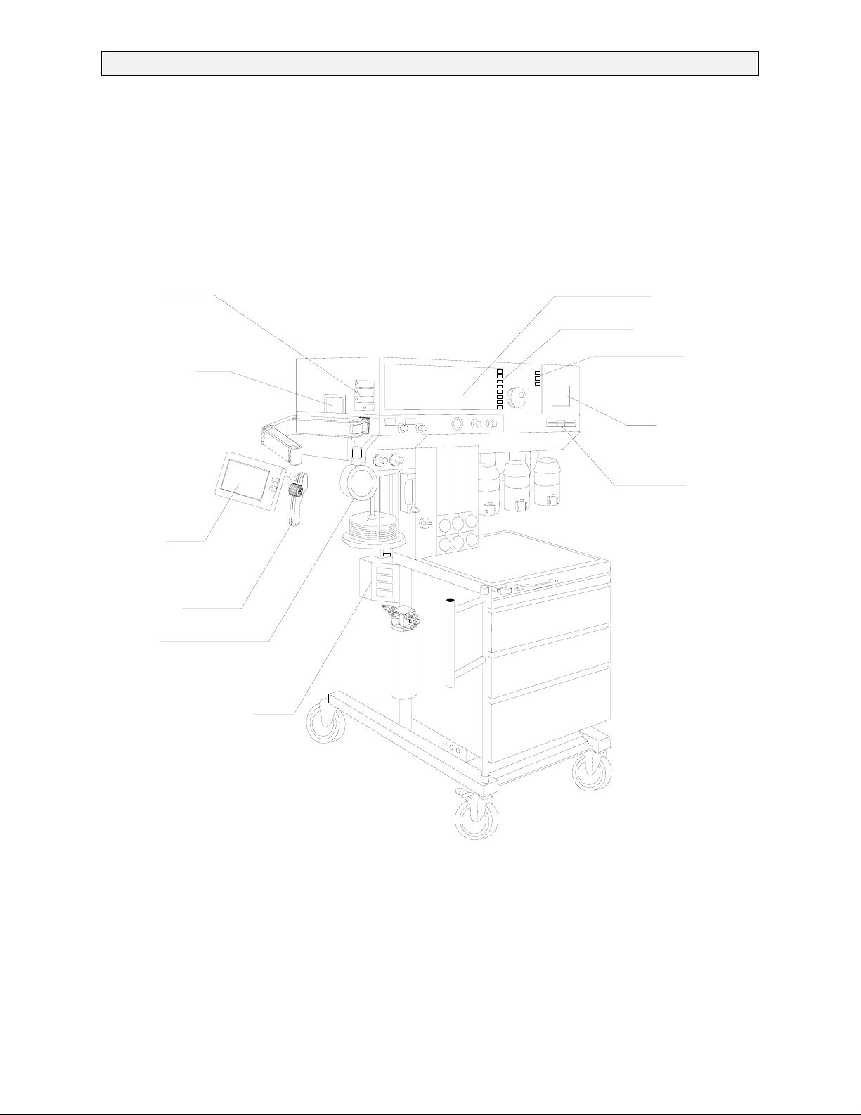
NARKOMED 4 ANESTHESIA SYSTEM
Y
A
R
RETURN TO THIS MANUAL'S TABLE OF CONTENTS
RETURN TO CD-ROM TABLE OF CONTENTS
PATIENT
INTERFACE
PANEL
DISPOSABLE
WATER TRAP
REMOTE
DISPLAY
DATAGRIP
MANUAL
SPHYGMOMANOMETER
MAIN DISPLA
MAIN KEY PANEL
CONTROL
KEY PANEL
STRIP CHART
PRINTER
O.R.DAT
MANAGE
BREATHING SYSTEM
SENSOR INTERFACE PANEL
(VPO ASSEMBLY)
SV45024
1-0 Rev. F
Page 9

RETURN TO THIS MANUAL'S TABLE OF CONTENTS
RETURN TO CD-ROM TABLE OF CONTENTS
NM4 INTRODUCTION
1.0 Recommendations
Because of the sophisticated nature of Draeger Medical, Inc. anesthesia equipment and its critical
importance in the operating room setting, it is highly recommended that only appropriately
trained and experienced professionals be permitted to service and maintain this equipment.
Please contact DrägerService® at (800) 543-5047 for service of this equipment.
Draeger Medical, Inc. also recommends that its anesthesia equipment be serviced at three-month
intervals. Periodic Manufacturer’s Service Agreements are available for equipment manufactured
by Draeger Medical, Inc. For further information concerning these agreements, please contact us
at (800) 543-5047.
Draeger Medical, Inc. products/material in need of factory repair shall be sent to:
DrägerService
3124 Commerce Drive
Telford, PA 18969
(Include RMA Number)
HOW TO USE THIS MANUAL
The manual is divided into several sections. The DIAGNOSTICS section describes self-test and
service diagnostics for checking the system functions. An understanding of the on-board service
capabilities is necessary before any attempt is made to troubleshoot the unit. The
TROUBLESHOOTING section lists error codes and provides troubleshooting guides to assist the
TSR in locating the source of a problem. The REPLACEMENT PROCEDURES section contains
instructions for removal and replacement of the assemblies that are considered field-replaceable.
The ADJUSTMENT AND CALIBRATION PROCEDURES section contains the field procedures
needed to restore original system specifications. The Periodic Manufacturer’s Service (PMS)
PROCEDURE section outlines the steps required to verify the electrical, mechanical and
pneumatic safety of the unit and also identifies components requiring periodic replacement.
GENERAL TROUBLESHOOTING GUIDELINES
Troubleshooting the Narkomed 4 should always begin by communicating withthose who observed
or experienced a problem with the unit. This may eliminate unnecessary troubleshooting steps.
Once a general problem is identified, refer to the troubleshooting flow charts in Section 3 to
determine the proper corrective action to be taken.
After a component has been replaced, verify that the unit is operating properly by running the
appropriate diagnostic procedure. The PMS PROCEDURE in Section 6 must also be performed
after any component has been replaced.
The general arrangement of the Narkomed 4 Anesthesia System is shown on the opposite page.
WARNINGS are used in this manual before procedures which if not performed correctly could
result in personal injury.
CAUTIONS are used in this manual to alert service personnel to the possibility of damage to the
equipment if a procedure is not performed correctly.
Rev. K
1-1
Page 10

RETURN TO THIS MANUAL'S TABLE OF CONTENTS
RETURN TO CD-ROM TABLE OF CONTENTS
INTRODUCTION NM4
Copyright
Copyright © 1999 by Draeger Medical, Inc. All rights reserved. No part of this publication
may be reproduced, transmitted, transcribed, or stored in a retrieval system in any form or
by any means, electronic or mechanical, including photocopying and recording, without the
written permission of Draeger Medical, Inc.
Trademark Notices
CliniDAS, Datagrip, NAD Information Systems, NAD Logo, Narkomed, O.R. Data Manager,
O.R. Link, ORM, PC Prep/View, Quality Service For Life, Vigilance Audit, Vitalert, Vitalink
and Narkomed GS are registered trademarks of Draeger Medical, Inc. All other products or
name brands are trademarks of their respective owners.
Disclaimer
The content of this manual is furnished for informational use only and is subject to change
without notice. Draeger Medical, Inc. assumes no responsibility or liability for any errors or
inaccuracies that may appear in this manual.
1-2
Rev. M
Page 11

RETURN TO THIS MANUAL'S TABLE OF CONTENTS
RETURN TO CD-ROM TABLE OF CONTENTS
NM4 DIAGNOSTICS
2.0 DIAGNOSTICS
The NARKOMED 4 contains a diagnostic system that monitors certain system functions and
records their operational status. A series of tests is performed when the system is powered
up and the results are displayed on the diagnostics screen shown in Figure 2-1. Further
diagnostic functions are available through a series of service screens that can be called up
by a Technical Service Representative at the display panel. The following paragraphs provide
a description of each of the service screens that can be accessed through touch keys on the
display panel. If no display is present upon system power-up, refer to Section 3 of this
manual for troubleshooting assistance.
A PREVENTIVE MAINTENANCE DUE message will appear on the screen if the current
date exceeds the Periodic Manufacturer’s Service due date stored in the machine.
DIAGNOSTICS
VIDEO TEST PASS
FIRMWARE TEST PASS
MEMORY TEST BANK1 PASS
MEMORY TEST BANK2 PASS
TIMER/INTERRUPT TEST PASS
ANALOG TEST PASS
AUDIO TEST -PRIMARY PASS
-BACKUP PASS POWER SUPPLY STATUS:
-SpO2 PASS FULLY FUNCTIONAL
SERIAL I/O TEST PASS
CLOCK TEST PASS
NON-VOLATILE MEMORY TEST PASS
ALTERNATE PROCESSOR TEST PASS
FUNCTIONAL
NARKOMED 4 SYSTEM SOFTWARE
(C) COPYRIGHT 1988-1995, NAD INC.
VERSION: 1.30 97 CF
MONITOR CHECKOUT
Rev. C
Figure 2-1: POWER-UP DIAGNOSTICS SCREEN
2-1
Page 12

RETURN TO THIS MANUAL'S TABLE OF CONTENTS
RETURN TO CD-ROM TABLE OF CONTENTS
DIAGNOSTICS (continued) NM4
2.1 Main Service Screen
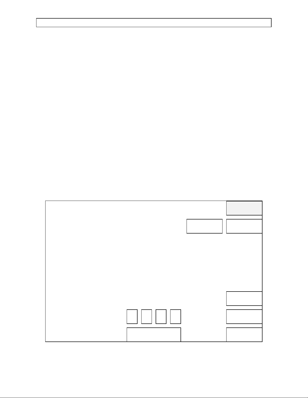
2.1.1 View Mode
To access the Main Service Screen, press and hold the Selection DIAL, and
simultaneously press the MONITOR and SYSTEM CONFIG keys. The View
mode service screen shown in Figure 2-2 will appear, displaying the machine
serial number, last service date and machine hours accumulated. Version
numbers for each software set in the machine are also displayed.
If the MONITORS service screens are accessed in the View mode, current
values will be displayed but the operator will not be able to perform
calibrations. A VIEW entry will not be logged into the Service Log.
MACHINE SERIAL NUMBER : 00124001
LAST SERVICE DATE : 03-14-96
HOURS RUNNING SINCE LAST SERVICE : 97
TOTAL HOURS RUNNING : 5610
SYSTEM SOFTWARE VERSION : 1.40
TOUCH PANEL SOFTWARE VERSION : 1.02
DATAGRIP SOFTWARE VERSION : 1.01
MULTISPEC SOFTWARE VERSION : 1.04
VPO SOFTWARE VERSION : 1.72
POWER SUPPLY SOFTWARE VERSION : 1.01
PURITAN BENNETT SW VERSION : 1.00 0016FF00
CRITICAR 1100 SW VERSION : 1.01 00171900
CRITICAR POET IQ SW VERSION : 1.00 00173D00
TRAM NET SW VERSION : 1.01 00175E00
SPACELAB LOGGER SW VERSION : 1.00 00178600
SERVICE CODE
VIEW
MAIN
SERVICE
LOG
PMS
CRITERIA
MONITORS
PERIPHERALS
Figure 2-2: VIEW MODE SERVICE SCREEN
2-2
Rev. H
Page 13
RETURN TO THIS MANUAL'S TABLE OF CONTENTS
RETURN TO CD-ROM TABLE OF CONTENTS
NM4 DIAGNOSTICS (continued)
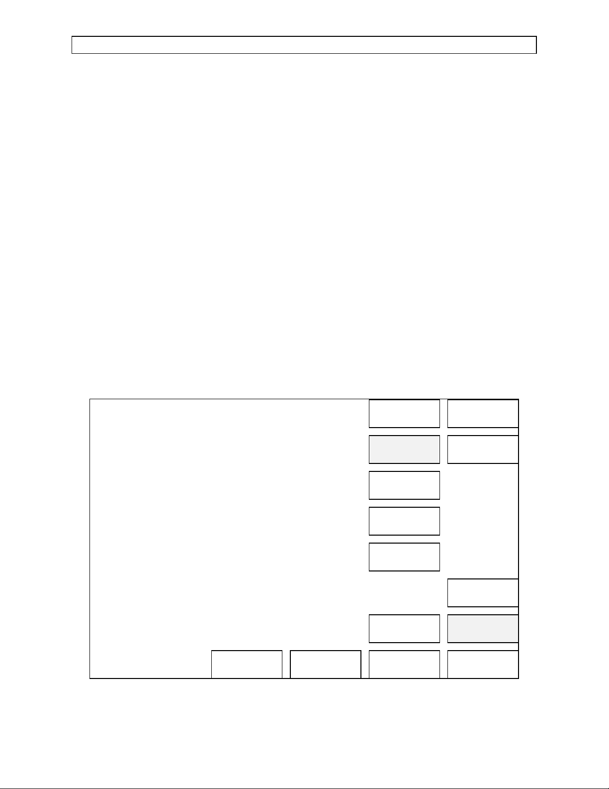
2.1.2 Service Mode
Touch the Service Code box on the screen, then scroll through the following list
of service codes with the Selection DIAL:
PMS: When performing scheduled Periodic Manufacturer’s Service.
INST: For initial installation of the NM4. This selection will establish
the start date for the warranty period.
SRVC: For unscheduled service visits requiring component
replacements or calibrations.
Press the Selection DIAL to enter the service event into the Service Log.
The Technical Service Representative ID boxes will appear on the screen as
shown in Figure 2-3. Touch the first box, scroll to the desired alpha-numeric
with the Selection DIAL, and press the dial to enter the first character of the
ID. Enter the remaining three characters in the same manner.After the ID has
been entered, the RESET key will be displayed.
NOTE: Following any service procedures, return to this screen and touch the
RESET key to enter the current date as the last service date, and to reset the
Hours Running Since Last Service to zero. Touching the RESET key also
places an entry into the service log.
MACHINE SERIAL NUMBER : 00124001
LAST SERVICE DATE : 03-14-96
HOURS RUNNING SINCE LAST SERVICE : 97
TOTAL HOURS RUNNING : 5610
SYSTEM SOFTWARE VERSION : 1.40
TOUCH PANEL SOFTWARE VERSION : 1.02
DATAGRIP SOFTWARE VERSION : 1.01
MULTISPEC SOFTWARE VERSION : 1.04
VPO SOFTWARE VERSION : 1.72
POWER SUPPLY SOFTWARE VERSION : 1.01
PURITAN BENNETT SW VERSION : 1.00 0016FF00
CRITICAR 1100 SW VERSION : 1.01 00171900
CRITICAR POET IQ SW VERSION : 1.00 00173D00
TRAM NET SW VERSION : 1.01 00175E00
SPACELAB LOGGER SW VERSION : 1.00 00178600
RESET
MAIN
SERVICE
LOG
PMS
CRITERIA
TECHNICAL SERVICE
REPRESENTATIVE I.D.
SERVICE CODE
0 0 0 0
SRVC
Figure 2-3: SERVICE MODE SERVICE SCREEN
Rev. H
MONITORS
PERIPHERALS
2-3
Page 14

RETURN TO THIS MANUAL'S TABLE OF CONTENTS
RETURN TO CD-ROM TABLE OF CONTENTS
DIAGNOSTICS (continued) NM4
2.2 Service Log Screen
Touch the SERVICE LOG key to display a list of stored events. Figure 2-4
shows a typical service log screen. The codes displayed are classified as Normal
Events, Failed Events, Error Events, Service Events, and Calibration Events.
These are listed in Tables 2-1 thru 2-6.
Up to 1000 events may be logged. Touching the PREV PAGE key will move the
display backward in time; touching the NEXT PAGE key will move the display
forward in time.
SERVICE LOG
DATE TIME PARAMETER CODE DESCRIPTION
07-14-91 18:10 0000FB64 0000 POWER ON
07-14-91 18:13 JOHN C009 RESP FLOW ZERO
07-14-91 18:19 JOHN C008 RESP FLOW SPAN
PREV
PAGE
NEXT
PAGE
PRINT
SERVICE LOG
MAIN
SERVICE
LOG
PMS
CRITERIA
MONITORS
PERIPHERALS
Figure 2-4: SERVICE LOG SCREEN
2-4
Rev. A
Page 15

RETURN TO THIS MANUAL'S TABLE OF CONTENTS
RETURN TO CD-ROM TABLE OF CONTENTS
NM4 DIAGNOSTICS (continued)
Table 2-1: NM4 SERVICE LOG NORMAL EVENT CODES
Code Description
0000 Power on
Table 2-2: NM4 SERVICE LOG FAILED EVENT CODES
Code Description Recommended Action
F011 QPDM Address Register Error
F012 QPDM Data Register Error
F013 QPDM Vblank Int Timeout Err
F014 QPDM VRAM Memory Error
F021 PROM CRC Test Error
F031 SRAM Memory Test Error
F051 MFP Bus Error
F052 MFP TimerA Error
F053 MFP TimerB Error
F054 MFP TimerC Error
F055 MFP TimerD Error
F056 System Clock Error
F057 FIFO Empty Interrupt Error
F058 ADC Interrupt Error
F059 CNTOVF Interrupt Error
F061 ADC Interrupt Error
F062 12V to -12V Out of Tol Error
Replace Processor
F063 5V to GND Out of Tol Error
F071 Pri Spkr Static Test Error
F072 Pri Spkr Dynamic Test Error
F073 Pri Spkr FIFO Test Error
F074 Pri Spkr No Vol Test Error
Rev. L
2-5
Page 16

RETURN TO THIS MANUAL'S TABLE OF CONTENTS
RETURN TO CD-ROM TABLE OF CONTENTS
DIAGNOSTICS (continued) NM4
Table 2-2 (continued): NM4 SERVICE LOG FAILED EVENT CODES
Code Description Recommended Action
F081 Backup Spkr Dynamic Test Err
F082 Backup Spkr No Vol Test Err
F091 SAO2 Spkr Static Test Error
F092 SAO2 Spkr Dynamic Test Error
F093 SAO2 Spkr No Vol Test Error
F111 Real Time Clock Test Error
F121 Bad File Warning
F122 Bad Files Error
F123 Event Memory Error
F130 Alt Processor Fail
F200 UART1 Internal Init Fail
F201 UART1 Register Readback Fail
F202 UART1 Transmit Interrupt Fail
F203 UART1 Receive Interrupt Fail
F204 UART1 Receive Err Int Fail
F205 UART1 Baud Rate Test 1 Fail
F206 UART1 Baud Rate Test 2 Fail
F207 UART1 Baud Rate Test 3 Fail
F210 UART1 Channel 0 Fail
F211 UART1 Channel 1 Fail
F212 UART1 Channel 2 Fail
F213 UART1 Channel 3 Fail
Replace Processor
2-6
Rev. L
Page 17

RETURN TO THIS MANUAL'S TABLE OF CONTENTS
RETURN TO CD-ROM TABLE OF CONTENTS
NM4 DIAGNOSTICS (continued)
Table 2-2 (continued): NM4 SERVICE LOG FAILED EVENT CODES
Code Description Recommended Action
F214 UART1 Channel 4 Fail
F215 UART1 Channel 5 Fail
F216 UART1 Channel 6 Fail
F217 UART1 Channel 7 Fail
F300 UART2 Internal Init Fail
F301 UART2 Register Readbk Fail
F302 UART2 Transmit Interrupt Fail
F303 UART2 Receive Interrupt Fail
F304 UART2 Receive Err Int Fail
F305 UART2 Baud Rate Test 1 Fail
F306 UART2 Baud Rate Test 2 Fail
F307 UART2 Baud Rate Test 3 Fail
F310 UART2 Channel 0 Fail
F311 UART2 Channel 1 Fail
F312 UART2 Channel 2 Fail
F313 UART2 Channel 3 Fail
F314 UART2 Channel 4 Fail
F315 UART2 Channel 5 Fail
F316 UART2 Channel 6 Fail
F317 UART2 Channel 7 Fail
Replace Processor
Rev. L
2-7
Page 18

RETURN TO THIS MANUAL'S TABLE OF CONTENTS
RETURN TO CD-ROM TABLE OF CONTENTS
DIAGNOSTICS (continued) NM4
Table 2-3: NM4 SERVICE LOG ERROR EVENTS
Touch Panel Events
Code Description Recommended Action
T001 Bad Device Recalibration Clear obstructions. If recurring,
replace touch panel
Head Assembly Events
Code Description Recommended Action
H001 Head Temperature Error Call Tech. Service
A001 Pattern Adjusted None
Power Supply Events
Code Description Recommended Action
P001 AC Fail Restore AC power
P002 AC Good None
P003 Battery Low Recharge battery. If persistent,
replace battery
P004 Battery Good None
P005 Brick Bad Replace Pwr Supply PCB
MSPEC Events
Code Description Recommended Action
M001 Channel Err Active CPU
M002 Channel Err Inactive CPU
M003 Command Retry
M004 Comm Error
M005 System Fault Max
Replace MSPEC
M006 Versiion ID Retry
M007 Span Fail
M008 Solenoid Stuck
M009 Zero Timeout
M010 Zero Fail Max
2-8
Rev. L
Page 19

RETURN TO THIS MANUAL'S TABLE OF CONTENTS
RETURN TO CD-ROM TABLE OF CONTENTS
NM4 DIAGNOSTICS (continued)
Table 2-3 (continued): NM4 SERVICE LOG ERROR EVENTS
MSPEC Events (continued)
Code Description Recommended Action
M011 RX Buffer Overflow Replace MSPEC
M012 No Continuous Data Replace MSPEC
M013 Line Block Diff Clear Blockage
M014 Line Block Less Than Min Clear Blockage
M016 Multispec Shutdown Replace MSPEC
M101 CD Chan Err
M102 Chan Err O2 Info P1
Call Tech. Service
M103 Chan Err O2 Info P2
Datagrip Events
DG00 Datagrip Internal Error
DG01 Datagrip Internal Error
Replace Datagrip
DG02 Datagrip Internal Error
Table 2-3 (continued): NM4 SERVICE LOG ERROR EVENTS
NIBP Events
Code Description Recommended Action
N001 NIBP Mon Error Replace NIBP
N002 NIBP Com Error Replace NIBP
N003 NIBP Bad Data Call Tech. Service
N004 Infl Pres Not GT 30 Check for Leaks
N005 Error Rcvd from NIBP Replace NIBP
N006 NIBP Mode Conflict Replace NIBP
2-8A Rev. L
Page 20

RETURN TO THIS MANUAL'S TABLE OF CONTENTS
RETURN TO CD-ROM TABLE OF CONTENTS
DIAGNOSTICS (continued) NM4
Table 2-4: NM4 SERVICE LOG SERVICE EVENT CODES
Code Description
S001 INST
S002 PMS
S003 SRVC
S004 Secondary Serv Screen Entry
S005 Reset Service Date
S006 Service Log Clear
Table 2-5: NM4 SERVICE LOG CALIBRATION EVENT CODES
Code Description Code Description
C001 O2 Store Zero A C009 Respiratory Flow Store Span
C002 O2 Store Zero B C010 Respiratory Flow Store Zero
C003 Line Block Store Reference C011 Pressure Store Span
C004 Gas Analyzer - Start C012 Pressure Store Zero
C005 Gas Analyzer - Continue C013 NIBP Infl Check
C006 NIBP Inflate C014 NIBP Defl Ck
C007 NIBP Stop C015 NIBP Leak Ck
C008 NIBP Take Reading
Rev. L 2-8B
Page 21

RETURN TO THIS MANUAL'S TABLE OF CONTENTS
RETURN TO CD-ROM TABLE OF CONTENTS
NM4 DIAGNOSTICS (continued)
Table 2-6: NM4 O.R. DATA MANAGER EVENT CODES
Code Description Recommended Action
V001 VTLK Com Error
Replace ORDM if recurring
V002 VTLK Com Lost
V003 VTLK Com Regained None
V010 ORDM Startup Failure
Replace ORDM
V011 ORDM Inact Startup Failure
Table 2-7: NM4 TEMPLATE EVENT CODES
Code Description Recommended Action
TEM0 Template Defaults Loaded
TEM1 Recreating Tmplt Database
TEM2 Templates Reinitalized
None
TEM3 Templates Reinitalized
TEM4 Factory Defaults Installed
2-8C Rev. L
Page 22

RETURN TO THIS MANUAL'S TABLE OF CONTENTS
RETURN TO CD-ROM TABLE OF CONTENTS
DIAGNOSTICS (continued) NM4
Touch the PRINT LOG key to obtain a Service Log Printout from the internal
printer. Figure 2-5 shows the format of the printed service log.
^^^^^^^^^^^^^^^^^^^^^^^^
************************
SERVICE LOG PRINTOUT
-----------------------MMDDYYHHMM PARAM CODE
0/714911819 JOHN C0/0/8
0/714911813 JOHN C0/0/9
0/714911810/0/0/0/0/FB64 0/0/0/0/
************************
Figure 2-5: SERVICE LOG PRINTOUT
Rev. L 2-8D
Page 23

RETURN TO THIS MANUAL'S TABLE OF CONTENTS
RETURN TO CD-ROM TABLE OF CONTENTS
NM4 DIAGNOSTICS (continued)
2.3 PMS Criteria Screen
Touch the PMS CRITERIA key to bring up the screen shown in Figure 2-6.
Touch the Month window, scroll to the next PMS due month with the Selection
DIAL, and press the dial to enter the month in which the PREVENTIVE
MAINTENANCE DUE message will appear on the power-up screen.
SELECT CRITERIA FOR "PREVENTIVE MAINTENANCE" MESSAGE
MONTH : 1991
DEC
MAIN
SERVICE
LOG
PMS
CRITERIA
MONITORS
PERIPHERALS
Figure 2-6: PMS CRITERIA SCREEN
2-9
Page 24

RETURN TO THIS MANUAL'S TABLE OF CONTENTS
RETURN TO CD-ROM TABLE OF CONTENTS
DIAGNOSTICS (continued) NM4
2.4 Monitors
Touch the MONITORS key to bring up a second column of touch keys. These
keys select the calibration screens for the system sensors.
2.4.1 Oxygen Monitor Screen
The Oxygen Monitor Screen displays current oxygen cell readings and
provides a calibration procedure forthe oxygen sensor circuitry. A touch
key allows entry of a new zero value. See Figure 2-7.
CURRENT CELL A: 110
CURRENT CELL B: 108
ZERO CALIBRATION PROCEDURE:
- REMOVE FUEL CELL FROM SENSOR HOUSING.
- LET CURRENT CELL VALUES STABILIZE.
- TOUCH "STORE ZERO" KEY TO ENTER
CURRENT VALUES AS CALIBRATED VALUES.
- DISCONNECT O2 SENSOR HOUSING CABLE
BEFORE RE-INSTALLING FUEL CELL.
- RE-INSTALL FUEL CELL.
- RE-CONNECT CABLE
STORED CELL A ZERO: 3
STORED CELL B ZERO: 6
STORE
ZERO
OXYGEN
PRESSURE
RESPIRATORY
FLOW
SpO2
NIBP
GAS
ANALYZER
LINE BLOCK
CALIBRATION
MAIN
SERVICE
LOG
PMS
CRITERIA
MONITORS
PERIPHERALS
Figure 2-7: OXYGEN MONITOR SCREEN
2-10
Page 25
RETURN TO THIS MANUAL'S TABLE OF CONTENTS
RETURN TO CD-ROM TABLE OF CONTENTS
NM4 DIAGNOSTICS (continued)
2.4.2 Breathing Pressure Monitor Screen
The Breathing Pressure Monitor Screen displays current airway
pressure and provides a calibration procedure for the pressure sensing
circuitry. Touch keys allow entry of new zero and span settings. See
Figure 2-8.
CURRENT PRESSURE VALUE : 205
ZERO CALIBRATION PROCEDURE:
- REMOVE PRESSURE SAMPLE LINE FROM
ABSORBER; EXPOSE TO AIR.
- LET CURRENT VALUE STABILIZE.
- TOUCH "STORE ZERO" KEY TO ENTER THE
CURRENT VALUE AS THE CALIBRATION ZERO.
SPAN CALIBRATION PROCEDURE:
- REMOVE PRESSURE SAMPLE LINE FROM
ABSORBER.
- APPLY 50 CM H2O CONSTANT PRESSURE AT
SAMPLE LINE, VERIFIED BY A KNOWN,
CALIBRATED METER.
- LET CURRENT VALUE STABILIZE.
- TOUCH "STORE SPAN" KEY TO ENTER THE
CURRENT VALUE AS THE CALIBRATION SPAN.
STORED ZERO: 244
STORED SPAN: 540
STORE
SPAN
STORE
ZERO
OXYGEN
PRESSURE
RESPIRATORY
FLOW
SpO2
NIBP
GAS
ANALYZER
LINE BLOCK
CALIBRATION
MAIN
SERVICE
LOG
PMS
CRITERIA
MONITORS
PERIPHERALS
Figure 2-8: BREATHING PRESSURE MONITOR SCREEN
2-11
Page 26

RETURN TO THIS MANUAL'S TABLE OF CONTENTS
RETURN TO CD-ROM TABLE OF CONTENTS
DIAGNOSTICS (continued) NM4
2.4.3 Respiratory Flow Monitor Screen
The Respiratory Flow Monitor Screen displays the current flow reading
and also shows a calibration procedure for the flow sensing circuitry.
Touch keys are provided for entry of new zero and span settings. See
Figure 2-9.
CURRENT FLOW VALUE : 76
ZERO CALIBRATION PROCEDURE:
- REMOVE SPIROMED SENSOR FROM ABSORBER.
- LET CURRENT VALUE STABILIZE.
- TOUCH "STORE ZERO" KEY TO ENTER THE
CURRENT VALUE AS THE CALIBRATION ZERO.
SPAN CALIBRATION PROCEDURE:
- REMOVE SPIROMED SENSOR FROM ABSORBER.
- ATTACH A GAS SUPPLY AT INPUT OF SENSOR,
AND A CALIBRATED FLOWMETER AT OUTPUT.
- PROVIDE A STEADY 10 L/MIN FLOW THROUGH
SPIROMED SENSOR.
- LET CURRENT VALUE STABILIZE.
- TOUCH "STORE SPAN" KEY TO ENTER THE
CURRENT VALUE AS THE CALIBRATION SPAN.
STORED ZERO: 78
STORED SPAN: 161
STORE
SPAN
STORE
ZERO
OXYGEN
PRESSURE
RESPIRATORY
FLOW
SpO2
NIBP
GAS
ANALYZER
LINE BLOCK
CALIBRATION
MAIN
SERVICE
LOG
PMS
CRITERIA
MONITORS
PERIPHERALS
Figure 2-9: RESPIRATORY FLOW MONITOR SCREEN
2-12
Page 27

RETURN TO THIS MANUAL'S TABLE OF CONTENTS
RETURN TO CD-ROM TABLE OF CONTENTS
NM4 DIAGNOSTICS (continued)
2.4.4 SpO2 Monitor Screen
The SpO2Screen displays current values for SpO2, Pulse, SpO2Pleth
and SpO
Bargraph. See Figure 2-10.
2
SpO2 VALUE : 98
PULSE VALUE : 75
PLETH VALUE : 125
BARGRAPH VALUE : 12
OXYGEN
PRESSURE
RESPIRATORY
FLOW
SpO2
NIBP
GAS
ANALYZER
LINE BLOCK
CALIBRATION
MAIN
SERVICE
LOG
PMS
CRITERIA
MONITORS
PERIPHERALS
Figure 2-10: SpO2MONITOR SCREEN
2-13
Page 28

RETURN TO THIS MANUAL'S TABLE OF CONTENTS
RETURN TO CD-ROM TABLE OF CONTENTS
DIAGNOSTICS (continued) NM4
2.4.5 NIBP Monitor Screen
The NIBP Monitor Screen displays Real Time, Systolic, Diastolic and
Mean blood pressure and Pulse.
The TAKE READING touch key will initiate a single NIBP
measurement cycle.
A procedure for checking NIBP cuff inflation pressure against an
external gauge is also displayed, with touch keys to perform the test.
See Figure 2-11.
Refer to Section 6 of this manual for inflation, deflation, and leak
testing procedures.
REAL TIME PRESSURE : 0
SYSTOLIC : 130
DIASTOLIC : 78
MEAN : 98
PULSE : 75
NIBP PRESSURE CALIBRATION VERIFICATION:
- PLACE A "T" IN LINE WITH THE BP CUFF.
- ATTACH A PRESSURE GAUGE AT "T".
- TOUCH THE "INFLATE" KEY.
- NIBP MODULE WILL INFLATE CUFF TO
180 MM Hg.
- VERIFY WITH PRESSURE GAUGE.
- TOUCH THE "STOP" KEY TO END THE TEST.
NIBP INFLATION, DEFLATION, AND LEAK CHECKS:
- REFER TO SERVICE MANUAL FOR PROCEDURES.
INFLATION
CHECK
DEFLATION
CHECK
READING
LEAKAGE
INFLATESTOP
TAKE
CHECK
OXYGEN
PRESSURE
RESPIRATORY
FLOW
SpO2
NIBP
GAS
ANALYZER
LINE BLOCK
CALIBRATION
MAIN
SERVICE
LOG
PMS
CRITERIA
MONITORS
PERIPHERALS
Figure 2-11: NIBP MONITOR SCREEN
2-14
Page 29

RETURN TO THIS MANUAL'S TABLE OF CONTENTS
RETURN TO CD-ROM TABLE OF CONTENTS
NM4 DIAGNOSTICS (continued)
2.4.6 Gas Analyzer Screen
Current values of CO2,N2O and anesthetic agent are displayed on the
Gas Analyzer Screen along with a span calibration procedure. See
Figure 2-12. (The scrubber bottle replacement instruction is not
displayed on machines having a Model 4610 gas analyzer.)
The MODE window on the gas analyzer screen displays the following
messages: INHIBIT during warm-up
READY after 30 minute warm-up
The STATUS window on the gas analyzer screen displays the following
messages: IDLE before starting calibration
ZERO IN PROGRESS during calibration
ZERO COMPLETE during calibration
SPAN IN PROGRESS during calibration
PASSED or FAILED after calibration
The complete calibration procedure is outlined in Section 5.
CURRENT CO2 : *INV* MODE:
CURRENT N2O : 10 STATUS:
CURRENT AGENT : *INV*
SPAN CALIBRATION PROCEDURE:
- WAIT FOR MODE = "READY".
- PERFORM GAS ANALYZER ACCURACY TEST.
- IF TEST FAILS, PERFORM SPAN CAL:
- WITH PATIENT CIRCUIT ENABLED:
- TOUCH "START" KEY,
- WAIT FOR STATUS = "ZERO COMPLETE"
- ATTACH SAMPLE LINE TO CALIBRATION BOTTLE.
- TURN FLOW ON BOTTLE TO 250 ML/MIN
- LET THE CURRENT CELL VALUES STABILIZE
- REMOVE THE SAMPLE LINE FROM THE BOTTLE
- TOUCH "CONTINUE" KEY.
- WAIT FOR STATUS = "PASSED" OR "FAILED"
- REPLACE SCRUBBER BOTTLE ANNUALLY.
OXYGEN
PRESSURE
RESPIRATORY
FLOW
SpO2
NIBP
GAS
ANALYZER
MAIN
SERVICE
LOG
PMS
CRITERIA
MONITORS
Figure 2-12: GAS ANALYZER SCREEN
Rev. C
2-15
STARTCONTINUE
LINE BLOCK
CALIBRATION
PERIPHERALS
Page 30

RETURN TO THIS MANUAL'S TABLE OF CONTENTS
RETURN TO CD-ROM TABLE OF CONTENTS
DIAGNOSTICS (continued) NM4
2.4.7 Line Block Screen
The current sample pressure is displayed on the Line Block screen
along with a calibration procedure and a touch key to enter a setpoint
value. See Figure 2-13. The stored reference value is displayed at the
lower left corner of the screen.
CURRENT SAMPLE PRESSURE: 200
LINE BLOCK CALIBRATION PROCEDURE:
- WITH PATIENT CIRCUIT ENABLED:
- ENSURE THAT SAMPLE LINE IS
CONNECTED AND UNOCCLUDED.
- PLACE A FLOWMETER AT THE SAMPLE
EXHAUST.
- ATTACH FLOW RESTRICTOR, FIX 0336, TO
PATIENT SAMPLE LINE.
- WAIT FOR VALID CURRENT SAMPLE PRESSURE.
- ADJUST RESTRICTION IN ORDER TO
OBTAIN A FLOW OF 100 ML/MIN.
- TOUCH "STORE REFERENCE" KEY.
- FULLY OCCLUDE SAMPLE LINE AND OBSERVE
THAT LINE BLOCK ALARM BECOMES
ACTIVE AFTER AT LEAST 15 SECONDS.
- REMOVE FLOW RESTRICTOR FROM SAMPLE LINE.
STORED REFERENCE : 200
REFERENCE
STORE
OXYGEN
PRESSURE
RESPIRATORY
FLOW
SpO2
NIBP
GAS
ANALYZER
LINE BLOCK
CALIBRATION
MAIN
SERVICE
LOG
PMS
CRITERIA
MONITORS
PERIPHERALS
Figure 2-13: LINE BLOCK CALIBRATION SCREEN
2-16
Page 31

RETURN TO THIS MANUAL'S TABLE OF CONTENTS
RETURN TO CD-ROM TABLE OF CONTENTS
NM4 DIAGNOSTICS (continued)
2.5 Peripherals
Touching the PERIPHERALS key brings up a second column of touch keys
that are used to select additional service screen functions. When
PERIPHERALS is selected, the Relays Status And Control Screen will appear
as shown in Figure 2-14.
2.5.1 Relays Status And Control Screen
Printer Relay:
When the ORDM key is selected, the external printer port is
connected to the O.R. DATA MANAGER. See Paragraph 2.8
Remote Panel Relay:
When the ORDM key is selected, the Remote Display will show
the O.R. DATA MANAGER functions. See Paragraph 2.6. When
the NM4 key is selected, the Remote Display shows the NM4
data and alarms.
RELAYS STATUS AND CONTROL SCREEN
PRINTER RELAY:
REMOTE PANEL RELAY:
ORDM NM4
ORDM NM4
RELAYS
DUMP
MAIN
SERVICE
LOG
PMS
CRITERIA
MONITORS
PERIPHERALS
Figure 2-14: RELAYS STATUS AND CONTROL SCREEN
Rev. A
2-17
Page 32

RETURN TO THIS MANUAL'S TABLE OF CONTENTS
RETURN TO CD-ROM TABLE OF CONTENTS
DIAGNOSTICS (continued) NM4
2.5.2 Service Dump Screen
The DUMP key will bring up the Service Dump Screen shown in Figure
2-15. This screen displays processor address and register debug
information. This screen should be checked whenever the machine is
serviced, and any non-zero codes that appear should be recorded and
reported to the N.A.D. Engineering Department.
Touch the PRINT DUMP key to print out the codes on the strip chart
recorder. Figure 2-16 shows the printed format of the Service Dump.
SERVICE DUMP SCREEN
D0-D3:
D4-D7:
A0-A3:
A4-A7:
SR/FO:
USP:
MSP:
ORVEC:
COUNT:
PSOS:
PSOS:
PSOS:
PSOS:
STACK:
STACK:
STACK:
00000000 00000000 00000000 00000000
00000000 00000000 00000000 00000000
00000000 00000000 00000000 00000000
00000000 00000000 00000000 00000000
00000000
PC:
00000000
00000000
00000000
ISP:
00000000
00000000
00000000
00000000 00000000 00000000 00000000
00000000 00000000 00000000 00000000
00000000 00000000 00000000 00000000
00000000 00000000
00000000 00000000 00000000 00000000
00000000 00000000 00000000 00000000
00000000 00000000 00000000 00000000
PRINT
DUMP
RELAYS
DUMP
MAIN
SERVICE
LOG
PMS
CRITERIA
MONITORS
PERIPHERALS
Figure 2-15: SERVICE DUMP SCREEN
2-18
Page 33

RETURN TO THIS MANUAL'S TABLE OF CONTENTS
RETURN TO CD-ROM TABLE OF CONTENTS
NM4 DIAGNOSTICS (continued)
^^^^^^^^^^^^^^^^^^^^^^^^
************************
SERVICE DUMP
------------------------
D0/-D1: 0/0/0/0/0/0/0/0/0/0/0/0/0/0/0/0/
D2-D3: 0/0/0/0/0/0/0/0/0/0/0/0/0/0/0/0/
D4-D5: 0/0/0/0/0/0/0/0/0/0/0/0/0/0/0/0/
D6-D7: 0/0/0/0/0/0/0/0/0/0/0/0/0/0/0/0/
A0/-A1: 0/0/0/0/0/0/0/0/0/0/0/0/0/0/0/0/
A2-A3: 0/0/0/0/0/0/0/0/0/0/0/0/0/0/0/0/
A4-A5: 0/0/0/0/0/0/0/0/0/0/0/0/0/0/0/0/
A6-A7: 0/0/0/0/0/0/0/0/0/0/0/0/0/0/0/0/
SR/FO: 0/0/0/0/0/0/0/0/
PC: 0/0/0/0/0/0/0/0/
USP: 0/0/0/0/0/0/0/0/
MSP: 0/0/0/0/0/0/0/0/
ISP: 0/0/0/0/0/0/0/0/
ORVEC: 0/0/0/0/0/0/0/0/
COUNT: 0/0/0/0/0/0/0/0/
PSOS: 0/0/0/0/0/0/0/0/0/0/0/0/0/0/0/0/
PSOS: 0/0/0/0/0/0/0/0/0/0/0/0/0/0/0/0/
PSOS: 0/0/0/0/0/0/0/0/0/0/0/0/0/0/0/0/
PSOS: 0/0/0/0/0/0/0/0/0/0/0/0/0/0/0/0/
PSOS: 0/0/0/0/0/0/0/0/0/0/0/0/0/0/0/0/
PSOS: 0/0/0/0/0/0/0/0/0/0/0/0/0/0/0/0/
PSOS: 0/0/0/0/0/0/0/0/0/0/0/0/0/0/0/0/
STACK: 0/0/0/0/0/0/0/0/0/0/0/0/0/0/0/0/
STACK: 0/0/0/0/0/0/0/0/0/0/0/0/0/0/0/0/
STACK: 0/0/0/0/0/0/0/0/0/0/0/0/0/0/0/0/
STACK: 0/0/0/0/0/0/0/0/0/0/0/0/0/0/0/0/
STACK: 0/0/0/0/0/0/0/0/0/0/0/0/0/0/0/0/
STACK: 0/0/0/0/0/0/0/0/0/0/0/0/0/0/0/0/
Figure 2-16: SERVICE DUMP PRINTOUT
2-19
Page 34

RETURN TO THIS MANUAL'S TABLE OF CONTENTS
RETURN TO CD-ROM TABLE OF CONTENTS
DIAGNOSTICS (continued) NM4
2.6 O.R. DATA MANAGER Diagnostics
During Power Up/Initialization and following completion of the NM4 boot
sequence, the O.R. DATA MANAGER performs diagnostic tests on its CPU.
Figures 2-17A and 2-17B show the O.R. DATA MANAGER boot information
that appears on the Remote Display.
Error messages may appear in the display at this time. If the keyboard is not
connected at power-up, a keyboard error message appears as shown in the
illustration. System configuration or set-up errors may also appear in the area
shown in the illustration. If an error message is displayed, the screen display
will freeze with a choice of options at the bottom of the screen. The
Troubleshooting Guides in Section 3 provide additional information that
correlates error messages to recommended hardware replacement.
386 Modular BIOS V 3.10/
Copyright (c) 1984 - 90/ Award Software Inc.
LB/386SX R2.0/ 4 Copyright (c) 1985 - 92 Ampro Computers, Inc.
TESTING INTERRUPT CONTROLLER #1 .............................. PASS
TESTING INTERRUPT CONTROLLER #2 .............................. PASS
TESTING CMOS BATTERY ........................................ PASS
TESTING CMOS CHECKSUM ...................................... PASS
SIZING SYSTEM MEMORY ...................................640/ K FOUND
TESTING SYSTEM MEMORY .................................. 640/ K PASS
TESTING UNEXPECTED INTERRUPTS AND STUCK NMI ................. PASS
TESTING PROTECTED MODE ...................................... PASS
SIZING EXTENDED MEMORY ............................... 0/ 7168K FOUND
TESTING MEMORY IN PROTECTED MODE ......................0/780/ 8K PASS
TESTING PROCESSOR EXCEPTION INTERRUPTS ...................... PASS
BIOS SHADOW RAM ......................................... ENABLED
CONFIGURATION OR SET-UP ERRORS APPEAR HERE
KEYBOARD ERROR OR NO KEYBOARD PRESENT
<PRESS CTRL-ALT-ESC FOR SETUP>
Figure 2-17A: O.R. DATA MANAGER POWER-UP DIAGNOSTICS SCREEN
2-20
Rev. A
Page 35

RETURN TO THIS MANUAL'S TABLE OF CONTENTS
RETURN TO CD-ROM TABLE OF CONTENTS
NM4 DIAGNOSTICS (continued)
Press ESC to abort Hard disk boot
Booting Hard Drive
Loading...
EMM 386 V1.21 /Frame = C0/0/0/ /Kb = 7168 /Bdos = FFFF
DR DOS Release 5.0/
Copyright (c) 1976, 1982, 1988, 1990 Digital Research Inc. All rights reserved.
Ampro Computers, Inc.
Executing runtime.bat on the hard drive.
Executing numoff.com.
Checking the CRC on ordm386.EXE with the CRC saved in the file CRC_ordm.
CRC calculation taking place.
Figure 2-17B: O.R. DATA MANAGER DIAGNOSTICS - SECOND SCREEN
2.7 O.R. DATA MANAGER Software Version Window
After power-up and when the O.R. DATA MANAGER is in its normal display
mode, the software version can be displayed by pressing the ALT and V keys
simultaneously. The window shown in Figure 2-18 will appear at the center of
the display for approximately three seconds. The message in parenthesis
(xxxxH) is an identifier that is unique to the particular software installation.
ORDM S/W Ver x.x (xxxxH)
Rev. A
Figure 2-18: SOFTWARE VERSION WINDOW
2-21
Page 36

RETURN TO THIS MANUAL'S TABLE OF CONTENTS
RETURN TO CD-ROM TABLE OF CONTENTS
DIAGNOSTICS (continued) NM4
2.8 Printer Configuration
The O.R. DATA MANAGER is configured to operate with the Hewlett Packard
LaserJet IIP Printer or the Hewlett Packard LaserJet IIIP Printer in the serial
port configuration. The following paragraphs describe how to runa printer selftest, and illustrate the configuration menus that appear on the self-test
printout page.
2.8.1 Hewlett Packard LaserJet IIP Printer Self-Test:
If the printer ON LINE indicator light is on, press the ON LINE key to
take the printer off-line.
While holding the down the ALT key, press the TEST key. The printer
display window will show 05 SELF TEST.
A few seconds later, 06 PRINT TEST will appear in the display window.
Two pages will print: the self-test printout page and a "cleaning" page.
The self-test printout page lists the settings for both the printer menu
and the configuration menu. The list should read as follows:
PRINTING MENU
COPIES 1
FONT SRC I (Internal)
FONT NUM 0
TRAYS LC ONLY
JOB SIZE LETTER
ORIENT P (Portrait)
LINES OF TXT 60
MAN FEED OFF
SYM SET ROMAN-8
CONFIGURATION MENU:
AUTOCONT ON
I/O SERIAL
BAUDRATE 9600
ROBUST XON ON
DTRPOLAR HI
RAM size: 1536K bytes
Firmware Datecode: 19890523
Internal Font Datecode: 19890213
Font Cartridges Installed: NO
Installed options: LC TRAY (LETTER)
If the self test printout differs from that shown in the illustration (with
the exception of Firmware Datecode and Internal Font Datecode), the
printer’s internal setup must be changed. Refer to the instructions in
the H-P LaserJet IIP Printer User’s Manual, Chapters 3 and 4,
supplied with the printer, for making any changes.
2-22
Page 37

RETURN TO THIS MANUAL'S TABLE OF CONTENTS
RETURN TO CD-ROM TABLE OF CONTENTS
NM4 DIAGNOSTICS (continued)
2.8.2 Hewlett Packard LaserJet IIIP Printer Self-Test:
If the printer ON LINE indicator light is on, press the ON LINE key to
take the printer off-line.
While holding the down the ALT key, press the TEST key. The printer
display window will show 05 SELF TEST.
A few seconds later, 06 PRINT TEST will appear in the display window.
Two pages will print: the self-test printout page and a "cleaning" page.
The self-test printout page lists the settings for both the printer menu
and the configuration menu. The list should read as follows:
PRINTING MENU:
MP SIZE LETTER
COPIES 1
FONT SRC I (Internal)
FONT NUM 0
TRAYS LC ONLY
JOB SIZE LETTER
ORIENT P (Portrait)
LINES OF TXT 60
MAN FEED OFF
SYM SET ROMAN-8
CONFIGURATION MENU:
AUTOCONT ON
I/O SERIAL
BAUDRATE 9600
ROBUST XON ON
DTRPOLAR HI
RET MEDIUM
RAM size: 1024K bytes
Page Count: 6574
Firmware Datecode: 19910523
Internal Font Datecode: 19910213
Font Cartridges Installed: NO
Installed options: LC TRAY (LETTER)
If the self test printout differs from that shown in the illustration (with
the exception of Page Count, Firmware Datecode and Internal Font
Datecode), the printer’s internal setup must be changed. Refer to the
instructions in the H-P LaserJet IIIP Printer User’s Manual,
Chapters2-4,supplied with the printer, for making any changes.
2-23
Page 38

RETURN TO THIS MANUAL'S TABLE OF CONTENTS
RETURN TO CD-ROM TABLE OF CONTENTS
Page 39

RETURN TO THIS MANUAL'S TABLE OF CONTENTS
RETURN TO CD-ROM TABLE OF CONTENTS
NM4 TROUBLESHOOTING GUIDE
3.0 TROUBLESHOOTING
This section contains information to assist the Draeger Medical, Inc. qualified
Technical Service Representative (TSR) in locating electrical faults affecting the
NARKOMED 4 monitoring and display devices. Since most troubleshooting efforts
begin with verifying power supply voltages, the following paragraphs outline the
voltage distribution scheme on the backplane along with power supply and test
connector pin identification.
Also contained in this section are troubleshooting guide flow charts that provide a
method of tracing faults to specific field replaceable assemblies or sub-assemblies in
response to observed failure modes or symptoms.
3.1 Power Supply and Voltage Distribution
3.1.1 In the NARKOMED 4, voltages are distributed to the processor boards
and peripheral devices from the backplane assembly. The TSR should
start the troubleshooting procedure with voltage checks at the
backplane. The wire harnesses originating at the power supply circuit
board are connected to J28, J29, and J30 on the backplane.
3.1.2 These voltages can also be measured at test connector J15 on later
model backplane assemblies. The acceptable voltage levels are listed in
Table 3-1. Figure 3-1 shows the location of these connectors on the
backplane. Refer to the replacement procedures in Section 4 for
instructions on access to the backplane assembly. Be sure to observe all
cautions that are listed.
3.1.3 If all the voltages are present, then ensure that all interconnecting
ribbon cables and wire harnesses between suspected assemblies are
properly seated. If all cables are properly seated, then proceed to the
troubleshooting guides.
3.1.4 If any voltage is missing from backplane connectors J28, J29 or J30,
proceed to the power supply voltage measurements in Paragraph 3.1.5.
Rev. H
3-1
Page 40

RETURN TO THIS MANUAL'S TABLE OF CONTENTS
RETURN TO CD-ROM TABLE OF CONTENTS
TROUBLESHOOTING GUIDE (continued) NM4
TABLE 3-1: BACKPLANE VOLTAGES
LOCATION
VOLTAGE ACCEPTABLE
TEST
CONNECTOR
POWER SUPPLY
CONNECTORS
RANGE
J15-30
J15-32
J15-33
J15-31
J15-17
J15-12
J15-18
J15-23
J15-24
J15-25
J15-27
J15-10
J15-13
J15-20
J15-14
J15-19
J15-21
J28-1
J28-4
J28-5
J28-2,3
J29-1,2
J29-5,6,7
J29-10,11
J29-16
J29-17
J29-18
J29-20
J29-12,13
J30-1,2
J30-5,6
J30-9,10
J30-13,14
J30-3,12
+5SaO2
+15SaO2
-15SaO2
COMMON
+12CRTA
+5VMAIN
+12CRTB
+5VNIBP
0**
+5VNIBP *
+12VPUMP
COMMON
+5VBKUP
+12VPP
+5VXTRA
+12CRTC
COMMON
* Was -12 V on machines with early NIBP assembly.
** Was +12 V on machines with early NIBP assembly.
4.85 to 5.15 VDC
14.25 to 15.75 VDC
-14.25 to -15.75 VDC
11.40 to 12.60 VDC
4.85 to 5.15 VDC
11.40 to 12.60 VDC
4.85 to 5.15 VDC
4.85 to 5.15 VDC
11.40 to 12.60 VDC
4.85 to 5.15 VDC
11.40 to 12.60 VDC
4.85 to 5.15 VDC
11.40 to 12.60 VDC
3-2
Rev. K
Page 41

NARKOMED 4 BACKPLANE CIRCUIT BOARD ASSEMBLY
J15 J28 J29 J30
NARKOMED 4 BACKPLANE CIRCUIT BOARD ASSEMBLY (EARLY MODELS)
SV49031
RETURN TO THIS MANUAL'S TABLE OF CONTENTS
RETURN TO CD-ROM TABLE OF CONTENTS
NM4 TROUBLESHOOTING GUIDE (continued)
Figure 3-1: BACKPLANE CONNECTORS FOR POWER SUPPLY CABLES
Rev. A
3-3
Page 42

RETURN TO THIS MANUAL'S TABLE OF CONTENTS
RETURN TO CD-ROM TABLE OF CONTENTS
TROUBLESHOOTING GUIDE (continued) NM4
3.1.5 The red lamps on the power supply circuit board assembly provide
diagnostic information on the status of the power supply. Figure 3-2
shows the location of these lamps. Refer to the replacement procedures
in Section 4 for instructions on access to the power supply circuit board.
The red LED (DS2) will be lighted if any of the power supply voltages
are out of tolerance. This lamp will also be lighted if the levels of the
two backup batteries differ by more than 1.1 volt. The red LED (DS4)
will be lighted during the power up self-test period, and will be off after
the self-test is completed. This lamp will remain lighted if there is a
powerup self-testfailure of themonitoring andcommunication circuitry
on the power supply board.
The DC-DC converters supplying the 5V bus are protected by
replaceable fuses F1 and F2, and the DC-DC converters supplying the
12V bus are protected by replaceable fuses F3, F4, and F5. Figure 3-2
shows the location of these fuses on the power supply circuit board.
Measure the voltages at connectors J1, J2 and J5 of the Power Supply
Circuit Board assembly. The acceptable voltage levels are listed in
Table 3-2. Figure 3-2 shows the location of these connectors on the
circuit board.
TABLE 3-2: POWER SUPPLY VOLTAGES
LOCATION VOLTAGE ACCEPTABLE RANGE
J1 - 1,2
J1 - 5,6
J1 - 9,10
J1 - 13,14
J1 - 17,18
J1 - 3,4,7,8
J2 - 1,2
J2 - 5,6,7
J2 - 10,11
J2-16
J2-17
*J2-18
J2-20
J2 - 3,4,8,9
+5VBKUP
+12VPP
+5VXTRA
+12CRTC
+12VMGM
COMMON
+12CRTA
+5VMAIN
+12CRTB
+5VNIBP
+12VNIBP
-12VNIBP
+12VPUMP
COMMON
4.85 to 5.15 VDC
11.40 to 12.60 VDC
4.85 to 5.15 VDC
11.40 to 12.60 VDC
11.40 to 12.60 VDC
11.40 to 12.60 VDC
4.85 to 5.15 VDC
11.40 to 12.60 VDC
4.85 to 5.15 VDC
11.40 to 12.60 VDC
-11.40 to -12.60 VDC
11.40 to 12.60 VDC
J5-1
J5-4
J5-5
J5 - 2,3
+5SaO2
+15SaO2
-15SaO2
COMMON
* Not used in later design
3-4
4.85 to 5.15 VDC
14.25 to 15.75 VDC
-14.25 to -15.75 VDC
Rev. C
Page 43

RETURN TO THIS MANUAL'S TABLE OF CONTENTS
RETURN TO CD-ROM TABLE OF CONTENTS
NM4 TROUBLESHOOTING GUIDE (continued)
TO BACKPLANE J23
TO ALARM
CHANNEL J4
DS3 (GREEN)
DS1 (GREEN)
DS4 (RED)
DS2 (RED)
POWER SUPPLY
CIRCUIT BOARD
ASSEMBLY
TO BACKPLANE J30
TO BACKPLANE J29
TO
BACKPLANE
J28
J3
J4
J1 J2
J5
TO MULTISPEC
POWER SUPPLY BOARD J2
F1
F2
F7
F6
J7
J8
F3
F4
F5
F8
J6
FROM BATTERY
AND POWER
TRANSFORMER COMPARTMENT
SV49032
Figure 3-2: POWER SUPPLY CIRCUIT BOARD CONNECTORS, LAMPS AND FUSES
Rev. A
3-5
Page 44

RETURN TO THIS MANUAL'S TABLE OF CONTENTS
RETURN TO CD-ROM TABLE OF CONTENTS
TROUBLESHOOTING GUIDE (continued) NM4
3.2 Processor Test
If a Processor related failure is reported, it will be flagged either as the "Main" or
the "Back-Up" processor board. When the System Power switch is turned ON, the
unit performs extensive self-diagnostics on its internal hardware. As the
diagnostics are performed, each test and its result (PASS - FAIL) appear on the
display. First the "Main" or upper processor board is tested and then the "BackUp" or lower processor board is tested. If the "Back-Up" processor is reported
defective, press the BACKUP key to obtain a more detailed display of what is nonfunctional on that board.
When diagnosing a processor related problem, use the BACKUP key to toggle
between processors. As an additional diagnostic aid, the green lamp on the edge
of each processor board, when lighted, indicates the presence of +5 VDC supplied
to that board. Refer to the replacement procedures Section 4 for instructions on
access to the processor boards.
3.3 Troubleshooting Guide Flow Charts
Table 3-3 lists failure modes that could be detected during the power-up self test
and the service diagnostic tests. Each failure mode is keyed to a troubleshooting
guide flow chart to assist the Technical Service Representative in locating the
problem. These flow charts assume that the machine is plugged into an AC outlet
with the correct voltage, and the machine is not running on its backup battery.
Table 3-3: NARKOMED 4 TROUBLESHOOTING GUIDES
FAILURE MODE CORRECTIVE ACTION
New Patient Alarm Not Displayed
Loss of O2Monitor
Loss of Breathing Pressure Monitor
Loss of GAS Monitor
Loss of Pulse Oximeter Monitor
Loss of Respiratory Volume Monitor
Loss of Blood Pressure Monitor
Touch Screen Failure
No Audio Alarms
DataScan function not Logging Data
Alarm Silence Failure
Vitalink Failure
Incorrect Display
Measure Data Incorrect
No Oxygen Ratio Monitor Alarm
No Oxygen Supply Pressure Alarm
Display Screens Blank upon System Power-Up
Power Supply Voltages Out of Tolerance
No Keypanel or Selection Dial Response
Internal Printer Not Working
GUIDE 1
GUIDE 2
GUIDE 3
GUIDE 4
GUIDE 5
GUIDE 6
GUIDE 7
GUIDE 8
GUIDE 9
GUIDE 10
GUIDE 11
GUIDE 12
GUIDE 13
GUIDE 14
GUIDE 15
GUIDE 16
GUIDE 17
GUIDE 18
GUIDE 19
GUIDE 20
3-6
Rev. A
Page 45

RETURN TO THIS MANUAL'S TABLE OF CONTENTS
RETURN TO CD-ROM TABLE OF CONTENTS
NM4 TROUBLESHOOTING GUIDE (continued)
GUIDE 1: New Patient Alarm Not Displayed
START
PROCESSOR TEST
N
PROCESSOR TEST
INDICATE PROCESSOR
PROCESSOR BOARD
ARE NEW
PATIENT ALARMS
PRESENT ON
CENTRAL ALARM
PANEL?
N
PERFORM
AS OUTLINED IN
PROCEDURE 3.2
DID
PROBLEM?
Y
REPLACE
AS OUTLINED IN
PROCEDURE 4.26
Y
ARE NEW
PATIENT ALARMS
PRESENT ON
CENTRAL ALARM
PANEL?
N
REINSTALL ORIGINAL
BACKPLANE ASSEMBLY
--------------------------------------
REPLACE REMOTE
DISPLAY AS
OUTLINED IN
PROCEDURE 4.32 OR 4.33
ARE NEW
PATIENT ALARMS
PRESENT ON
CENTRAL ALARM
PANEL?
Y
Y
Rev. A
ARE NEW
PATIENT ALARMS
PRESENT ON
CENTRAL ALARM
PANEL?
N
REINSTALL ORIGINAL
PROCESSOR BOARD
---------------------------------REPLACE BACKPLANE
ASSEMBLY AS
OUTLINED IN
PROCEDURE 4.28
Y
REINSTALL ORIGINAL
REMOTE DISPLAY
N
CONTACT NAD
SERVICE DEPT.
N
PERFORM A
COMPLETE PMS
ON THE UNIT
DOES UNIT
PASS PMS?
Y
UNIT IS
FUNCTIONAL
3-7
Page 46

RETURN TO THIS MANUAL'S TABLE OF CONTENTS
RETURN TO CD-ROM TABLE OF CONTENTS
TROUBLESHOOTING GUIDE (continued) NM4
GUIDE 2: Loss of O
START
CONNECT OXYGEN
SENSOR CABLE TO
INTERFACE PANEL
Y
Monitor
2
IS
"O2 MON ERR"
DISPLAYED ON
CENTRAL ALARM
PANEL?
IS
"O2 SENS DISC"
DISPLAYED ON
CENTRAL ALARM
PANEL?
REPLACE
OXYGEN SENSOR
AS OUTLINED IN
PROCEDURE 4.39
N
Y
REINSTALL ORIGINAL
VPO BOARD
----------------------------------
PERFORM PROCESSOR
BOARD TEST
AS OUTLINED IN
PROCEDURE 3.2
N
N
DID
PROCESSOR TEST
INDICATE PROCESSOR
PROBLEM?
IS
"O2 MON ERR"
DISPLAYED ON
CENTRAL ALARM
PANEL?
Y
REINSTALL ORIGINAL
OXYGEN SENSOR
---------------------------------REPLACE VPO BOARD
AS OUTLINED IN
PROCEDURE 4.37
IS
"O2 MON ERR"
DISPLAYED ON
CENTRAL ALARM
PANEL?
Y
Y
N
N
REPLACE
PROCESSOR BOARD
AS OUTLINED IN
PROCEDURE 4.26
IS
"O2 MON ERR"
DISPLAYED ON
CENTRAL ALARM
PANEL?
Y
REINSTALL ORIGINAL
PROCESSOR BOARD
CONTACT NAD
SERVICE DEPT.
N
PERFORM A
COMPLETE PMS
ON THE UNIT
DOES UNIT
PASS PMS?
Y
UNIT IS
FUNCTIONAL
N
3-8
Rev. A
Page 47

RETURN TO THIS MANUAL'S TABLE OF CONTENTS
RETURN TO CD-ROM TABLE OF CONTENTS
NM4 TROUBLESHOOTING GUIDE (continued)
GUIDE 3: Loss of Breathing Pressure Monitor
START
CONNECT
PILOT LINE TO
INTERFACE PANEL
IS "BAROMED
ERROR" PRESENT
ON CENTRAL ALARM
N
LINE CONNECTED
TO INTERFACE
VPO BOARD
AS OUTLINED IN
PROCEDURE 4.37
IS "BAROMED
ERROR" PRESENT
ON CENTRAL ALARM
REINSTALL ORIGINAL
VPO BOARD
----------------------------------
PERFORM PROCESSOR
BOARD TEST
AS OUTLINED IN
PROCEDURE 3.2
PANEL?
IS PILOT
PANEL?
Y
REPLACE
PANEL?
N
Y
REPLACE
PROCESSOR BOARD
AS OUTLINED IN
PROCEDURE 4.26
IS "BAROMED
ERROR" PRESENT
ON CENTRAL ALARM
PANEL?
Y
N
REINSTALL ORIGINAL
PROCESSOR BOARD
Y
CONTACT NAD
SERVICE DEPT.
N
N
PERFORM A
COMPLETE PMS
ON THE UNIT
DOES UNIT
PASS PMS?
Y
UNIT IS
FUNCTIONAL
Rev. A
DID
PROCESSOR TEST
INDICATE PROCESSOR
PROBLEM?
Y
N
3-9
Page 48

RETURN TO THIS MANUAL'S TABLE OF CONTENTS
RETURN TO CD-ROM TABLE OF CONTENTS
TROUBLESHOOTING GUIDE (continued) NM4
GUIDE 4: Loss of GAS Monitor
START
REPLACE OCCLUDED
SAMPLE LINE OR
WATER TRAP
AGT ERR"PRESENT
ON CENTRAL ALARM
Y
LINE BLK" PRESENT
ON CENTRAL ALARM
REPLACE MULTISPEC
ANALYZER ASSEMBLY
AS OUTLINED IN
PROCEDURE 4.29
N
AGT ERR"PRESENT
ON CENTRAL ALARM
IS "CO2/
PANEL?
IS "CO2
PANEL?
OR 4.30
IS "CO2/
PANEL?
N
Y
N
N
IS "CO2/
AGT ERR"PRESENT
ON CENTRAL ALARM
PANEL?
N
REPLACE
PROCESSOR BOARD
AS OUTLINED IN
PROCEDURE 4.26
IS "CO2/
AGT ERR"PRESENT
ON CENTRAL ALARM
PANEL?
Y
REINSTALL ORIGINAL
PROCESSOR BOARD
Y
REPLACE BACKPLANE
ASSEMBLY AS
OUTLINED IN
PROCEDURE 4.28
IS "CO2/
AGT ERR"PRESENT
ON CENTRAL ALARM
PANEL?
Y
REINSTALL ORIGINAL
BACKPLANE ASSEMBLY
N
Y
REINSTALL ORIGINAL
MULTISPEC ANALYZER
----------------------------------
PERFORM PROCESSOR
BOARD TEST
AS OUTLINED IN
PROCEDURE 3.2
3-10
PERFORM A
COMPLETE PMS
ON THE UNIT
DOES UNIT
PASS PMS?
Y
UNIT IS
FUNCTIONAL
N
CONTACT NAD
SERVICE DEPT.
Rev. A
Page 49

RETURN TO THIS MANUAL'S TABLE OF CONTENTS
RETURN TO CD-ROM TABLE OF CONTENTS
NM4 TROUBLESHOOTING GUIDE (continued)
GUIDE 5: Loss of Pulse Oximetry Monitor
START
CHECK
CONNECTIONS
BETWEEN SENSOR
AND SPO2
CABLE
CONNECTOR
CONNECT
SPO2 CABLE TO
INTERFACE PANEL
"OXIMETER ERR"
DISPLAYED ON
CENTRAL ALARM
Y
SENS DISC" PRESENT
ON CENTRAL ALARM
N
CABLE CONNECTED
TO INTERFACE
PULSE OXIMETER
(SPO2) ASSEMBLY
AS OUTLINED IN
PROCEDURE 4.36
IS
PANEL?
IS "OXI
PANEL?
IS SPO2
PANEL?
REPLACE
N
Y
N
N
Y
IS SPO2
MONITOR DISPLAY
PANEL BLANK?
Y
REPLACE
BACKPLANE
ASSEMBLY AS
OUTLINED IN
PROCEDURE 4.28
IS SPO2
MONITOR DISPLAY
PANEL BLANK?
Y
REINSTALL ORIGINAL
BACKPLANE ASSEMBLY
N
REPLACE
PROCESSOR BOARD
AS OUTLINED IN
PROCEDURE 4.26
IS SPO2
MONITOR DISPLAY
PANEL BLANK?
Y
REINSTALL ORIGINAL
PROCESSOR BOARD
N
Rev. A
N
IS SPO2
MONITOR DISPLAY
PANEL BLANK?
REINSTALL ORIGINAL
SPO2 SENSOR
CIRCUIT ASSEMBLY
-----------------------------------PERFORM PROCESSOR
BOARD TEST
AS OUTLINED IN
PROCEDURE 3.2
PERFORM A
Y
COMPLETE PMS
ON THE UNIT
DOES UNIT
PASS PMS
Y
UNIT IS
FUNCTIONAL
N
CONTACT NAD
SERVICE DEPT.
3-11
Page 50

RETURN TO THIS MANUAL'S TABLE OF CONTENTS
RETURN TO CD-ROM TABLE OF CONTENTS
TROUBLESHOOTING GUIDE (continued) NM4
GUIDE 6: Loss of Respiratory Volume Monitor
START
CONNECT
SENSOR CORD TO
INTERFACE PANEL
Y
IS
"SPIROMED ERR"
DISPLAYED ON
CENTRAL ALARM
PANEL?
Y
IS
"VOL SEN DISC"
DISPLAYED ON
RESP. VOLUME
MONITOR?
N
REPLACE
RESPIRATORY
VOLUME SENSOR
AS OUTLINED IN
PROCEDURE 4.38
IS
"SPIROMED ERR"
DISPLAYED ON
CENTRAL ALARM
PANEL?
Y
N
REINSTALL ORIGINAL
VPO BOARD
-------------------------------------REPLACE BACKPLANE
ASSEMBLY AS
OUTLINED IN
PROCEDURE 4.28
IS
"SPIROMED ERR"
DISPLAYED ON
CENTRAL ALARM
PANEL?
Y
N
REINSTALL ORIGINAL
BACKPLANE ASSEMBLY
N
PERFORM A
COMPLETE PMS
ON THE UNIT
REINSTALL ORIGINAL
RESP. VOLUME SENSOR
-------------------------------------REPLACE VPO BOARD
AS OUTLINED IN
PROCEDURE 4.37
IS
"SPIROMED ERR"
DISPLAYED ON
CENTRAL ALARM
PANEL?
Y
CONTACT NAD
SERVICE DEPT.
N
3-12
N
DOES UNIT
PASS PMS?
Y
UNIT IS
FUNCTIONAL
Rev. A
Page 51

RETURN TO THIS MANUAL'S TABLE OF CONTENTS
RETURN TO CD-ROM TABLE OF CONTENTS
NM4 TROUBLESHOOTING GUIDE (continued)
GUIDE 7: Loss of Blood Pressure Monitor
CHECK CUFF
CONNECTION
AT PATIENT
INTERFACE
PANEL
CHECK FOR
LEAKS AT
NIBP CUFF,
REPLACE CUFF
IF NECESSARY
START
Y
Y
IS "NIBP
MON ERROR"
DISPLAYED ON
CENTRAL ALARM
PANEL?
N
IS "NIBP
CUFF DISC"
DISPLAYED ON
CENTRAL ALARM
PANEL?
N
IS "NIBP
CUFF ERROR"
DISPLAYED ON
CENTRAL ALARM
PANEL?
N
PERFORM
PROCESSOR TEST
AS OUTLINED IN
PROCEDURE 3.2
IS "NIBP
MON ERROR"
DISPLAYED ON
CENTRAL ALARM
PANEL?
N
REPLACE
PROCESSOR BOARD
AS OUTLINED IN
PROCEDURE 4.26
IS "NIBP
MON ERROR"
DISPLAYED ON
CENTRAL ALARM
PANEL?
REPLACE NIBP PUMP
AND SENSOR CIRCUIT
Y
REINSTALL ORIGINAL
NIBP PUMP AND SENSOR
CIRCUIT ASSEMBLY
-----------------------------------------REPLACE BACKPLANE
ASSEMBLY AS
OUTLINED IN
PROCEDURE 4.35
IS "NIBP
MON ERROR"
DISPLAYED ON
CENTRAL ALARM
PANEL?
Y
ASSEMBLY AS
OUTLINED IN
PROCEDURE 4.28
IS "NIBP
MON ERROR"
DISPLAYED ON
CENTRAL ALARM
PANEL?
N
NN
Rev. A
REINSTALL ORIGINAL
PROCESSOR BOARD
CONTACT NAD
SERVICE DEPT.
3-13
YY
REINSTALL ORIGINAL
BACKPLANE ASSEMBLY
PERFORM A
COMPLETE PMS
ON THE UNIT
N
DOES UNIT
PASS PMS?
Y
UNIT IS
FUNCTIONAL
Page 52

RETURN TO THIS MANUAL'S TABLE OF CONTENTS
RETURN TO CD-ROM TABLE OF CONTENTS
TROUBLESHOOTING GUIDE (continued) NM4
GUIDE 8: Touch Screen Failure
START
Y
RESPONSIVE?
PROCESSOR TEST
AS OUTLINED IN
PROCEDURE 3.2
RESPONSIVE?
REPLACE FRONT
BEZEL ASSEMBLY
AS OUTLINED IN
PROCEDURE 4.31
IS TOUCH
SCREEN
N
PERFORM
IS TOUCH
SCREEN
N
REINSTALL ORIGINAL
FRONT BEZEL ASSEMBLY
-----------------------------------------REPLACE BACKPLANE
ASSEMBLY AS
OUTLINED IN
PROCEDURE 4.28
IS TOUCH
SCREEN
RESPONSIVE?
Y
REINSTALL ORIGINAL
BACKPLANE ASSEMBLY
REPLACE
PROCESSOR BOARD
AS OUTLINED IN
PROCEDURE 4.26
IS TOUCH
SCREEN
RESPONSIVE?
NN
REINSTALL ORIGINAL
PROCESSOR BOARD
YY
IS TOUCH
SCREEN
RESPONSIVE?
Y
PERFORM A
COMPLETE PMS
ON THE UNIT
N
CONTACT NAD
SERVICE DEPT.
3-14
N
DOES UNIT
PASS PMS?
Y
UNIT IS
FUNCTIONAL
Rev. A
Page 53

RETURN TO THIS MANUAL'S TABLE OF CONTENTS
RETURN TO CD-ROM TABLE OF CONTENTS
NM4 TROUBLESHOOTING GUIDE (continued)
GUIDE 9: No Audio Alarms
START
ARE WARNINGS
AND CAUTIONS AUDIBLY
ANNUNCIATED?
N
CHECK
WIRING HARNESS
FROM SPEAKER
TO BACKPLANE
ARE WARNINGS
AND CAUTIONS AUDIBLY
ANNUNCIATED?
N
REPLACE
SPEAKER
Y
ARE WARNINGS
AND CAUTIONS AUDIBLY
ANNUNCIATED?
N
REPLACE
BACKPLANE PCB
ASM OUTLINED IN
SECTION 4.28
Y
ARE WARNINGS
AND CAUTIONS AUDIBLY
ANNUNCIATED?
N
Y
Y
REPLACE MAIN
PROCESSOR BOARD
AS OUTLINED IN
SECTION 4.26
ARE WARNINGS
AND CAUTIONS AUDIBLY
ANNUNCIATED?
N
Y
Rev. A
ARE WARNINGS
AND CAUTIONS AUDIBLY
ANNUNCIATED?
N
REINSTALL
ORIGINAL SPEAKER
--------------------------------
PERFORM PROCESSOR
BOARD TEST
AS OUTLINED IN
SECTION 3.2
REINSTALL ORIGINAL
BACKPLANE PCB
Y
CONTACT NAD
SERVICE DEPT.
REINSTALL ORIGINAL
PROCESSOR BOARD
PERFORM A
COMPLETE PMS
ON THE UNIT
N
FUNCTIONAL
DOES UNIT
PASS PMS?
Y
UNIT IS
3-15
Page 54

RETURN TO THIS MANUAL'S TABLE OF CONTENTS
RETURN TO CD-ROM TABLE OF CONTENTS
TROUBLESHOOTING GUIDE (continued) NM4
GUIDE 10: DataScan Function not Logging Data
START
ARE
DATASCAN
READINGS PRESENT
ON REMOTE
DISPLAY?
Y
REPLACE
REMOTE DISPLAY
AS OUTLINED IN
PROCEDURE 4.32 OR 4.33
Y
Y
DATASCAN
READINGS PRESENT
ON REMOTE
DISPLAY?
REINSTALL ORIGINAL
REMOTE DISPLAY
------------------------------------REPLACE FRONT
BEZEL ASSEMBLY
AS OUTLINED IN
PROCEDURE 4.31
DATASCAN
READINGS PRESENT
ON REMOTE
DISPLAY?
ARE
ARE
N
N
Y
N
ARE
DATASCAN
READINGS PRESENT
ON REMOTE
DISPLAY?
N
REPLACE
BACKPLANE ASSEMBLY
AS OUTLINED IN
PROCEDURE 4.28
ARE
DATASCAN
READINGS PRESENT
ON REMOTE
DISPLAY?
N
REINSTALL ORIGINAL
BACKPLANE ASSEMBLY
PERFORM A
COMPLETE PMS
ON THE UNIT
Y
REPLACE
PROCESSOR BOARD
AS OUTLINED IN
PROCEDURE 4.26
ARE
DATASCAN
READINGS PRESENT
ON REMOTE
DISPLAY?
N
REINSTALL ORIGINAL
PROCESSOR BOARD
Y
REINSTALL ORIGINAL
FRONT BEZEL ASSEMBLY
------------------------------------
PERFORM PROCESSOR
BOARD TEST
AS OUTLINED IN
PROCEDURE 3.2
DOES UNIT
PASS PMS?
Y
UNIT IS
FUNCTIONAL
3-16
N
CONTACT NAD
SERVICE DEPT.
Rev. A
Page 55

RETURN TO THIS MANUAL'S TABLE OF CONTENTS
RETURN TO CD-ROM TABLE OF CONTENTS
NM4 TROUBLESHOOTING GUIDE (continued)
GUIDE 11: Alarm Silence Failure
START
SILENCE
FUNCTION OK AT
MAIN AND REMOTE
PANELS
Y
N
SILENCE
FUNCTION FAIL AT
MAIN PANEL
ONLY?
CHECK CABLES:
BEZEL ASM TO
BACKPLANE J4;
SWITCH PANEL TO
TOUCH PANEL PCB J3
SILENCE
FUNCTION OK AT
MAIN PANEL ?
REPLACE FRONT
BEZEL ASSEMBLY
AS OUTLINED IN
PROCEDURE 4.31
SILENCE
FUNCTION OK AT
MAIN PANEL ?
N
SILENCE
FUNCTION FAIL AT
REMOTE PANEL
ONLY?
CHECK INTERNAL
CABLE FROM PATIENT
INTERFACE PANEL TO
BACKPLANEJ8
YY
SILENCE
FUNCTION OK AT
REMOTE PANEL ?
REPLACE
REMOTE DISPLAY
AS OUTLINED IN
PROCEDURE 4.32 OR 4.33
YY
SILENCE
FUNCTION OK AT
REMOTE PANEL ?
NN
YY
NN
N
PERFORM
PROCESSOR BOARD
TEST AS OUTLINED
IN SECTION 3.2
SILENCE
FUNCTION OK AT
MAIN AND REMOTE
PANELS
REPLACE MAIN
PROCESSOR BOARD
Y
SILENCE
FUNCTION OK AT
MAIN AND REMOTE
PANELS
REINSTALL ORIGINAL
PROCESSOR BOARD
----------------------------------REPLACE BACKPLANE
AS OUTLINED IN
PROCEDURE 4.28
N
Y
N
Rev. A
UNIT IS
FUNCTIONAL
REINSTALL ORIGINAL
BEZEL ASSEMBLY
PERFORM A
COMPLETE PMS
ON THE UNIT
DOES UNIT
PASS PMS?
3-17
REINSTALL ORIGINAL
REMOTE DISPLAY
NY
Y
FUNCTION OK AT
MAIN AND REMOTE
REINSTALL ORIGINAL
BACKPLANE
CONTACT NAD
SERVICE DEPT.
SILENCE
PANELS
N
Page 56

RETURN TO THIS MANUAL'S TABLE OF CONTENTS
RETURN TO CD-ROM TABLE OF CONTENTS
TROUBLESHOOTING GUIDE (continued) NM4
GUIDE 12: Vitalink Failure
START
CONNECT
PERIPHERAL DEVICE
TO CORRECT SERIAL
INTERFACE PORT
DOES HOST
FAIL TO COMMUNICATE
WITH PERIPHERAL
N
PERIPHERAL
CABLE CONNECTED TO
SERIAL INTERFACE
CHECK PERIPHERAL
DEVICE AND HOST
SERIAL PORT
CONFIGURATION
SETTINGS
DOES HOST
FAIL TO COMMUNICATE
WITH PERIPHERAL
DEVICE?
IS
PORT?
DEVICE?
N
Y
Y
N
Y
REINSTALL ORIGINAL
SERIAL INTERFACE
---------------------------------
BACKPLANE ASSEMBLY
AS OUTLINED IN
PROCEDURE 4.28
N
FAIL TO COMMUNICATE
WITH PERIPHERAL
REINSTALL ORIGINAL
BACKPLANE ASSEMBLY
------------------------------------PROCESSOR BOARD
AS OUTLINED IN
PROCEDURE 4.26
ASSEMBLY
REPLACE
DOES HOST
DEVICE?
Y
REPLACE
REPLACE SERIAL
INTERFACE ASSEMBLY
AS OUTLINED IN
PROCEDURE 4.27
DOES HOST
FAIL TO COMMUNICATE
WITH PERIPHERAL
DEVICE?
Y
DOES HOST
FAIL TO COMMUNICATE
WITH PERIPHERAL
DEVICE?
Y
N
REINSTALL ORIGINAL
PROCESSOR BOARD
CONTACT NAD
SERVICE DEPT.
N
3-18
N
PERFORM A
COMPLETE PMS
ON THE UNIT
DOES UNIT
PASS PMS?
Y
UNIT IS
FUNCTIONAL
Rev. A
Page 57

RETURN TO THIS MANUAL'S TABLE OF CONTENTS
RETURN TO CD-ROM TABLE OF CONTENTS
NM4 TROUBLESHOOTING GUIDE (continued)
GUIDE 13: Incorrect Display
START
IS WRONG
MONITOR SCREEN
DISPLAYED?
Y
REPLACE
BACKPLANE ASSEMBLY
AS OUTLINED IN
PROCEDURE 4.28
IS WRONG
MONITOR SCREEN
DISPLAYED?
Y
REINSTALL ORIGINAL
BACKPLANE ASSEMBLY
N
N
PERFORM A
COMPLETE PMS
ON THE UNIT
DOES UNIT
PASS PMS?
Y
N
Rev. A
CONTACT NAD
SERVICE DEPT.
UNIT IS
FUNCTIONAL
3-19
Page 58

RETURN TO THIS MANUAL'S TABLE OF CONTENTS
RETURN TO CD-ROM TABLE OF CONTENTS
TROUBLESHOOTING GUIDE (continued) NM4
GUIDE 14: Measure Data Incorrect
START
IS MEASURE
DATA INCORRECT?
Y
REPLACE MULTISPEC
ANALYZER ASSEMBLY
AS OUTLINED IN
PROCEDURE 4.29 OR 4.30
IS MEASURE
DATA INCORRECT?
Y
REINSTALL ORIGINAL
MULTISPEC
ANALYZER ASSEMBLY
------------------------------------ENSURE THAT
COOLING FANS
ARE OPERATING
N
N
PERFORM A
COMPLETE PMS
ON THE UNIT
IS MEASURE
DATA INCORRECT?
Y
CONTACT NAD
SERVICE DEPT.
N
3-20
N
DOES UNIT
PASS PMS?
Y
UNIT IS
FUNCTIONAL
Rev. A
Page 59

RETURN TO THIS MANUAL'S TABLE OF CONTENTS
RETURN TO CD-ROM TABLE OF CONTENTS
NM4 TROUBLESHOOTING GUIDE (continued)
GUIDE 15: No Oxygen Ratio Monitor Alarm
START
IS O2/N2O
RATIO ALARM
FUNCTIONAL?
N
REPLACE ALARM
CHANNEL ASSEMBLY
AS OUTLINED IN
PROCEDURE 4.21
IS O2/N2O
RATIO ALARM
FUNCTIONAL?
N
REINSTALL ORIGINAL
ALARM CHANNEL
ASSEMBLY
-------------------------------------CHECK ORMC
ADJUSTMENTS
AS OUTLINED IN
PROCEDURE 5.4
Y
IS O2/N2O
RATIO ALARM
FUNCTIONAL?
N
REPLACE
Y
BACKPLANE ASSEMBLY
AS OUTLINED IN
PROCEDURE 4.28
IS O2/N2O
RATIO ALARM
FUNCTIONAL?
N
REINSTALL ORIGINAL
BACKPLANE ASSEMBLY
Y
Y
PERFORM A
COMPLETE PMS
ON THE UNIT
Rev. A
CONTACT NAD
SERVICE DEPT.
3-21
N
DOES UNIT
PASS PMS?
Y
UNIT IS
FUNCTIONAL
Page 60

RETURN TO THIS MANUAL'S TABLE OF CONTENTS
RETURN TO CD-ROM TABLE OF CONTENTS
TROUBLESHOOTING GUIDE (continued) NM4
GUIDE 16: No Oxygen Supply Pressure Alarm
START
DOES
OXYGEN SUPPLY
PRESSURE ALARM
FUNCTION?
N
CHECK
WIRE HARNESS
FROM ALARM SWITCH
TO ALARM CHANNEL
DOES
OXYGEN SUPPLY
PRESSURE ALARM
FUNCTION?
N
REPLACE OXYGEN
SUPPLY PRESSURE
ALARM SWITCH
AS OUTLINED IN
PROCEDURE 4.8
OR 4.22
Y
REINSTALL
ORIGINAL OXYGEN
SUPPLY PRESSURE
ALARM SWITCH
----------------------------------------REPLACE ALARM
CHANNEL ASSEMBLY
AS OUTLINED IN
PROCEDURE 4.21 OR 4.22
Y
DOES
OXYGEN SUPPLY
PRESSURE ALARM
FUNCTION?
N
REINSTALL ORIGINAL
ALARM CHANNEL
ASSEMBLY
Y
PERFORM A
COMPLETE PMS
ON THE UNIT
DOES
OXYGEN SUPPLY
PRESSURE ALARM
FUNCTION?
N
CONTACT NAD
SERVICE DEPT.
Y
3-22
N
DOES UNIT
PASS PMS?
Y
UNIT IS
FUNCTIONAL
Rev. A
Page 61

RETURN TO THIS MANUAL'S TABLE OF CONTENTS
RETURN TO CD-ROM TABLE OF CONTENTS
NM4 TROUBLESHOOTING GUIDE (continued)
GUIDE 17: Display Screens Blank upon System Power-Up
START
ARE BOTH
DISPLAY PANELS
BLANK ON SYSTEM
POWER UP?
Y
REPLACE
BACKPLANE ASSEMBLY
AS OUTLINED IN
PROCEDURE 4.28
ARE BOTH
DISPLAY PANELS
BLANK ON SYSTEM
POWER UP?
Y
REINSTALL ORIGINAL
BACKPLANE ASSEMBLY
------------------------------------REPLACE FRONT
BEZEL ASSEMBLY
AS OUTLINED IN
PROCEDURE 4.31
N
ARE BOTH
DISPLAY PANELS
BLANK ON SYSTEM
POWER UP
Y
REINSTALL ORIGINAL
N
FRONT BEZEL
ASSEMBLY
CONTACT NAD
SERVICE DEPT.
N
PERFORM A
COMPLETE PMS
ON THE UNIT
N
DOES UNIT
PASS PMS?
Y
UNIT IS
FUNCTIONAL
Rev. A
3-23
Page 62

RETURN TO THIS MANUAL'S TABLE OF CONTENTS
RETURN TO CD-ROM TABLE OF CONTENTS
TROUBLESHOOTING GUIDE (continued) NM4
GUIDE 18: Power Supply Voltages Out of Tolerance
START
ARE
POWER SUPPLY
VOLTAGES OUT OF
TOLERANCE?
Y
REPLACE POWER
SUPPLY CIRCUIT BOARD
AS OUTLINED IN
PROCEDURE 4.25
ARE
POWER SUPPLY
VOLTAGES OUT OF
TOLERANCE?
Y
REINSTALL ORIGINAL
POWER SUPPLY
CIRCUIT BOARD
N
N
COMPLETE PMS
N
PERFORM A
ON THE UNIT
DOES UNIT
PASS PMS?
CONTACT NAD
SERVICE DEPT.
3-24
Y
UNIT IS
FUNCTIONAL
Rev. A
Page 63

RETURN TO THIS MANUAL'S TABLE OF CONTENTS
RETURN TO CD-ROM TABLE OF CONTENTS
NM4 TROUBLESHOOTING GUIDE (continued)
GUIDE 19: No Keypanel or Selection Dial Response
START
ARE KEYPANEL
AND SELECTION DIAL
RESPONSIVE?
N
REPLACE FRONT
BEZEL ASSEMBLY
AS OUTLINED IN
PROCEDURE 4.31
ARE KEYPANEL
AND SELECTION DIAL
RESPONSIVE?
N
REINSTALL ORIGINAL
FRONT BEZEL ASSEMBLY
-----------------------------------REPLACE
BACKPLANE ASSEMBLY
AS OUTLINED IN
PROCEDURE 4.28
Y
ARE KEYPANEL
AND SELECTION DIAL
RESPONSIVE
N
Y
REINSTALL ORIGINAL
BACKPLANE ASSEMBLY
CONTACT NAD
SERVICE DEPT.
Y
PERFORM A
COMPLETE PMS
ON THE UNIT
N
DOES UNIT
PASS PMS?
Y
UNIT IS
FUNCTIONAL
Rev. A
3-25
Page 64

RETURN TO THIS MANUAL'S TABLE OF CONTENTS
RETURN TO CD-ROM TABLE OF CONTENTS
TROUBLESHOOTING GUIDE (continued) NM4
GUIDE 20: Internal Printer Not Working
START
CONNECT PRINTER
CABLE TO
BACKPLANE J1
DOES
INTERNAL PRINTER
FUNCTION?
N
N
IS PRINTER
CABLE
CONNECTED?
Y
REPLACE
INTERNAL PRINTER
AS OUTLINED IN
PROCEDURE 4.43
DOES
INTERNAL PRINTER
FUNCTION?
N
REINSTALL ORIGINAL
INTERNAL PRINTER
------------------------------------REPLACE
BACKPLANE ASSEMBLY
AS OUTLINED IN
PROCEDURE 4.28
Y
DOES
INTERNAL PRINTER
FUNCTION?
N
REINSTALL ORIGINAL
BACKPLANE ASSEMBLY
Y
CONTACT NAD
SERVICE DEPT.
Y
PERFORM A
COMPLETE PMS
ON THE UNIT
N
DOES UNIT
PASS PMS?
Y
UNIT IS
FUNCTIONAL
3-26
Rev. A
Page 65

RETURN TO THIS MANUAL'S TABLE OF CONTENTS
RETURN TO CD-ROM TABLE OF CONTENTS
NM4 TROUBLESHOOTING GUIDE (continued)
3.4 O.R. DATA MANAGER Troubleshooting
Table 3-4 lists failure modes and symptoms for the O.R. DATA MANAGER.
Those that are marked (*) in the table are messages that can appear on the
Remote Display during the power-up self test. Each failure mode or symptom
is keyed to a recommended action to assist the TSR in locating a problem.
Refer to the Replacement Procedures section for instructions on access to the
O.R. DATA MANAGER CPU assembly, cable connections and keyboard.
TABLE 3-4: O. R. DATA MANAGER FAILURE MODES AND SYMPTOM LIST
FAILURE MODE OR SYMPTOM ACTION
Display Blank
*Keyboard Error or Keyboard Not Present
*Internal Diagnostic Failure upon System Power-Up
*Memory Battery Fail
*CMOS Checksum Fail
*Interrupt Controller #1 Fail
*Interrupt Controller #2 Fail
*Memory in Protected Mode Fail
*Protected Mode Fail
*Processor Exception Interrupts Fail
*Sizing System Memory 640K Not Found
*System Memory 640K Fail
*Sizing Extended Memory 00384K Not Found
*Communications Error with Host
*Disk Error
*Disk Full Error
*Disk Invalid Error
*Disk Not Inserted Error
*"B" Drive Error Messages
Printer Inoperative
GUIDE 21
GUIDE 22
GUIDE 23
GUIDE 23
GUIDE 23
GUIDE 23
GUIDE 23
GUIDE 23
GUIDE 23
GUIDE 23
GUIDE 23
GUIDE 23
GUIDE 23
GUIDE 24
GUIDE 25
GUIDE 25
GUIDE 25
GUIDE 25
GUIDE 26
GUIDE 27
Rev. A
3-27
Page 66

RETURN TO THIS MANUAL'S TABLE OF CONTENTS
RETURN TO CD-ROM TABLE OF CONTENTS
TROUBLESHOOTING GUIDE (continued) NM4
GUIDE 21: Display Blank
START
FIRST:
REMOVE AC POWER
-----------------------------CONNECT REMOTE
DISPLAY CABLE TO
INTERFACE PANEL
------------------------------
RESTORE AC POWER
CHECK CABLE
CONNECTIONS:
INTERFACE PANEL
TO BACKPLANE J8
IS REMOTE
DISPLAY BLANK?
N
N
IS REMOTE
DISPLAY
PLUGGED IN?
IS INTERFACE
PANEL CABLE
CONNECTED?
SWITCH REMOTE PANEL
RELAY AS OUTLINED IN
PARAGRAPH 2.4.1
IS REMOTE
DISPLAY BLANK IN BOTH
NM4 AND ORDM
MODES?
N
Y
N
Y
Y
N
IS REMOTE
DISPLAY BLANK
IN ORDM MODE
ONLY?
N
IS REMOTE
DISPLAY BLANK
IN NM4 MODE
ONLY?
Y
SWITCH TO
BACKUP PROCESSOR
Y
CONTACT NAD
SERVICE DEPT.
Y
REPLACE
REMOTE DISPLAY
AS OUTLINED IN
PROCEDURE 4.32 OR 4.33
IS REMOTE
DISPLAY BLANK IN BOTH
NM4 AND ORDM
MODES?
Y
REINSTALL ORIGINAL
REMOTE DISPLAY
3-28
N
YN
REINSTALL ORIGINAL
BACKPLANE ASSEMBLY
IS REMOTE
DISPLAY BLANK IN BOTH
MAIN AND BACKUP
PROCESSORS?
Y
REPLACE
BACKPLANE ASSEMBLY
AS OUTLINED IN
PROCEDURE 4.28
IS REMOTE
DISPLAY BLANK?
FUNCTIONAL
N
UNIT IS
Rev. A
Page 67

RETURN TO THIS MANUAL'S TABLE OF CONTENTS
RETURN TO CD-ROM TABLE OF CONTENTS
NM4 TROUBLESHOOTING GUIDE (continued)
GUIDE 21: Display Blank (continued)
IS REMOTE
DISPLAY BLANK IN
MAIN PROCESSOR
ONLY?
REINSTALL ORIGINAL
REMOTE DISPLAY
-------------------------------------CHECK ORDM VIDEO
CABLE CONNECTIONS:
VIDEO INTERFACE BOARD
J3 TO BACKPLANE J14
(ALSO CHECK POWER
CONNECTIONS TO CPU
ASSEMBLY)
N
IS REMOTE
DISPLAY BLANK?
Y
REPLACE
BACKPLANE ASSEMBLY
AS OUTLINED IN
PROCEDURE4.28
IS REMOTE
DISPLAY BLANK?
Y
REINSTALL ORIGINAL
BACKPLANE ASSEMBLY
------------------------------------REPLACE ORDM
VIDEO CABLE
IS REMOTE
DISPLAY BLANK?
Y
N
N
N
Rev. A
REPLACE MAIN
PROCESSOR BOARD
N
DISPLAY BLANK?
Y
IS REMOTE
Y
REPLACE BACKUP
PROCESSOR BOARD
CONTACT NAD
SERVICE DEPT.
3-29
REINSTALL ORIGINAL
VIDEO CABLE
---------------------------------REPLACE CPU
ASSEMBLY AS
OUTLINED IN
PROCEDURE 4.44
OR 4.45
IS REMOTE
DISPLAY BLANK?
Y
REINSTALL ORIGINAL
CPU ASSEMBLY
N
UNIT IS
FUNCTIONAL
Page 68

RETURN TO THIS MANUAL'S TABLE OF CONTENTS
RETURN TO CD-ROM TABLE OF CONTENTS
TROUBLESHOOTING GUIDE (continued) NM4
GUIDE 22: Keyboard Error or Keyboard Not Present
START
CHECK KEYBOARD
CABLE CONNECTIONS:
INTERNAL KEYBOARD
CABLE TO CPU BOARD J5;
ALSO CHECK FLOATING
KEYBOARD CABLE
CONNECTOR IN
MONITOR BOX
N
IS KEYBOARD
ERROR PRESENT
DURING SYSTEM
POWER-UP?
Y
IS KEYBOARD
CABLE CONNECTED
TO CPU?
Y
REPLACE
KEYBOARD
ASSEMBLY AS
OUTLINED IN
PROCEDURE 4.46
IS KEYBOARD
ERROR PRESENT
DURING SYSTEM
POWER-UP?
N
IS KEYBOARD
ERROR PRESENT
DURING SYSTEM
POWER-UP?
Y
REINSTALL
ORIGINAL CPU
ASSEMBLY
CONTACT NAD
SERVICE DEPT.
N
N
Y
REINSTALL ORIGINAL
KEYBOARD ASSEMBLY
-------------------------------------REPLACE CPU
AS OUTLINED IN
PROCEDURE 4.44 OR 4.45
3-30
UNIT IS
FUNCTIONAL
Rev. A
Page 69

RETURN TO THIS MANUAL'S TABLE OF CONTENTS
RETURN TO CD-ROM TABLE OF CONTENTS
NM4 TROUBLESHOOTING GUIDE (continued)
GUIDE 23: Internal Diagnostic, Interrupt Controller, or Memory Failure
START
DO ANY
POWER-UP DIAGNOSTIC
TESTS FAIL OR SET-UP
ERRORS OCCUR?
Y
REPLACE
CPU ASSEMBLY
AS OUTLINED IN
PROCEDURE 4.44
OR 4.45
DO ANY
POWER-UP DIAGNOSTIC
TESTS FAIL OR SET-UP
ERRORS OCCUR?
Y
N
N
Rev. A
REINSTALL
ORIGINAL CPU
ASSEMBLY
CONTACT NAD
SERVICE DEPT.
UNIT IS
FUNCTIONAL
3-31
Page 70

RETURN TO THIS MANUAL'S TABLE OF CONTENTS
RETURN TO CD-ROM TABLE OF CONTENTS
TROUBLESHOOTING GUIDE (continued) NM4
GUIDE 24: Communications Error with Host
START
IS "ORDM
COM ERROR" PRESENT
ON REMOTE DISPLAY
ADVISORY?
Y
SWITCH REMOTE PANEL
RELAY TO ORDM AS
OUTLINED IN PARA. 2.4.1
----------------------------------------CHECK CONFIG OF ORDM:
REF. SETUP AND
INSTALLATION SECTION OF
NM4 OPERATOR'S MANUAL
--------------------------------------RETURN RELAY TO
NM4 MODE
IS "ORDM
COM ERROR" PRESENT
ON REMOTE DISPLAY
ADVISORY?
Y
SWITCH TO
BACKUP PROCESSOR
IS "ORDM
COM ERROR" PRESENT IN
BOTH MAIN AND BACKUP
PROCESSORS?
Y
N
REPLACE
DATA CABLE
IS "ORDM
COM ERROR" PRESENT
ON REMOTE DISPLAY
ADVISORY?
Y
REINSTALL ORIGINAL
DATA CABLE
N
IS "ORDM
COM ERROR" PRESENT
IN MAIN PROCESSOR
ONLY?
N
PROCESSOR BOARD
Y
REPLACE MAIN
N
REPLACE BACKUP
PROCESSOR BOARD
--------------------------------REPLACE ORDM CPU
AS OUTLINED IN
PROCEDURE 4.44 OR 4.45
IS "ORDM
COM ERROR" PRESENT
ON REMOTE DISPLAY
ADVISORY?
Y
REINSTALL
ORIGINAL CPU
ASSEMBLY
N
N
IS INTERNAL
DATA CABLE
CONNECTED?
N
CHECK DATA CABLE
CONNECTIONS:
CPU BOARD J3
TO BACKPLANE J3
Y
IS "ORDM
COM ERROR" PRESENT
ON REMOTE DISPLAY
ADVISORY?
Y
CONTACT NAD
SERVICE DEPT.
3-32
N
CONTACT NAD
SERVICE DEPT.
UNIT IS
FUNCTIONAL
Rev. A
Page 71

RETURN TO THIS MANUAL'S TABLE OF CONTENTS
RETURN TO CD-ROM TABLE OF CONTENTS
NM4 TROUBLESHOOTING GUIDE (continued)
GUIDE 25: Disk Errors
START
DOES
"DISK ERROR"
FLASH ON REMOTE
DISPLAY?
N
DOES
"DISK NOT INSERTED"
FLASH ON REMOTE
DISPLAY?
N
DOES
"DISK INVALID"
FLASH ON REMOTE
DISPLAY?
REPLACE DISK
WITH A
FORMATTED
3-1/2" HIGH
DENSITY DISK
INSERT FORMATTED
DATA DISK INTO
DISK DRIVE
REPLACE DISK
WITH A
FORMATTED
3-1/2" HIGH
DENSITY DISK
DOES
"DISK ERROR"
FLASH ON REMOTE
DISPLAY?
N
DOES
"DISK NOT INSERTED"
FLASH ON REMOTE
DISPLAY?
N
DOES
"DISK INVALID"
FLASH ON REMOTE
DISPLAY?
NN
YY
YY
YY
DOES
"DISK FULL"
FLASH ON REMOTE
DISPLAY?
N
UNIT IS
FUNCTIONAL
N
"DISK GENERAL ERROR"
FLASH ON REMOTE
REPLACE DISK
WITH A
FORMATTED
3-1/2" HIGH
DENSITY DISK
DOES
DISPLAY?
Y
REINSTALL
ORIGINAL CPU
ASSEMBLY
DOES
"DISK FULL"
FLASH ON REMOTE
DISPLAY?
N
REPLACE
CPU ASSEMBLY
AS OUTLINED IN
PROCEDURE 4.44
OR 4.45
CONTACT NAD
SERVICE DEPT.
YY
Rev. A
3-33
Page 72

RETURN TO THIS MANUAL'S TABLE OF CONTENTS
RETURN TO CD-ROM TABLE OF CONTENTS
TROUBLESHOOTING GUIDE (continued) NM4
GUIDE 26: "B" Drive Error Messages
START
ARE ANY
"B" DRIVE ERRORS
SHOWN ON REMOTE
DISPLAY?
Y
REPLACE MEMORY
BATTERY AS
OUTLINED IN
PROCEDURE 4.44
ARE ANY
"B" DRIVE ERRORS
SHOWN ON REMOTE
DISPLAY?
Y
REPLACE CPU
ASSEMBLY
AS OUTLINED IN
PROCEDURE 4.44
OR 4.45
N
N
ARE ANY
"B" DRIVE ERRORS
SHOWN ON REMOTE
DISPLAY?
Y
REINSTALL
ORIGINAL CPU
ASSEMBLY
CONTACT NAD
SERVICE DEPT.
N
3-34
UNIT IS
FUNCTIONAL
Rev. A
Page 73

RETURN TO THIS MANUAL'S TABLE OF CONTENTS
RETURN TO CD-ROM TABLE OF CONTENTS
NM4 TROUBLESHOOTING GUIDE (continued)
GUIDE 27: Printer Inoperative
START
CONNECT
EXTERNAL PRINTER
CABLE
CONNECT PRINTER
POWER CORD
CHECK
PRINTER CABLE
CONNECTIONS:
CPU BOARD J2 TO
BACKPLANE J13
(ALSO CHECK
SERIAL INTERFACE
BOARD J6 TO
BACKPLANE J2)
DOES
EXTERNAL PRINTER
FUNCTION?
N
N
N
EXT. PRINTER
CABLE CONNECTED
TO PRINTER
PORT?
IS EXTERNAL
PRINTER POWER CORD
CONNECTED?
IS PRINTER
INTERNAL CABLE
CONNECTED?
Y
N
IS
DOES
EXTERNAL PRINTER
FUNCTION?
Y
ORIGINAL CABLE
----------------------------REPLACE ORDM
CPU ASSEMBLY
AS OUTLINED IN
PROCEDURE 4.44
Y
EXTERNAL PRINTER
Y
N
REINSTALL
OR 4.45
DOES
FUNCTION?
N
Y
Y
Rev. A
DOES
EXTERNAL PRINTER
FUNCTION?
N
REPLACE
PRINTER
CABLE
3-35
REINSTALL
ORIGINAL ORDM
Y
CPU ASSEMBLY
CONTACT
NAD SERVICE
DEPARTMENT
UNIT IS
FUNCTIONAL
Page 74

RETURN TO THIS MANUAL'S TABLE OF CONTENTS
RETURN TO CD-ROM TABLE OF CONTENTS
Page 75

RETURN TO THIS MANUAL'S TABLE OF CONTENTS
RETURN TO CD-ROM TABLE OF CONTENTS
NM4 REPLACEMENT PROCEDURES
4.0 REPLACEMENT PROCEDURES
This section outlines removal and replacement procedures for the field-replaceable
assemblies of the NARKOMED 4 Anesthesia System.
These procedures are to be performed only by a Draeger Medical, Inc. qualified
Technical Service Representative (TSR).
The following are the only procedures authorized by Draeger Medical, Inc. to be
performed in the field. All other service procedures shall be referred to Draeger
Medical, Inc.’s Technical Service Department.
NOTE: The PMS PROCEDURE given in Section 6 must be performed
after any replacement, removal, calibration or adjustment
procedure.
Rev. H
4-1
Page 76

RETURN TO THIS MANUAL'S TABLE OF CONTENTS
RETURN TO CD-ROM TABLE OF CONTENTS
REPLACEMENT PROCEDURES (continued) NM4
4.1 Cylinder Yoke Assemblies
Each cylinder yoke contains a replaceable filter and check valve assembly.
Replacement of this assembly requires that the yoke be removed from the
anesthesia machine. Figure 4-1 shows a typical cylinder yoke mounting
arrangement. Access to the yoke mounting screws and gas line connection
requires that the table top be removed from the machine.
4.1.1 Disconnect all pipeline hoses and set the System Power switch to ON.
4.1.2 Close all cylinder valves except the O
valve.
2
4.1.3 Set the oxygen flow to 5 liters per min.
4.1.4 Open the other gas flow control valves to drain pressure from the
system.
4.1.5 Close the O
the O
Flush valve to drain oxygen pressure from the system.
2
cylinder valve, and close the flow control valves. Press
2
4.1.6 Set the System Power switch to STANDBY.
4.1.7 Remove the cylinder where the yoke is to be replaced.
WARNING: Store the cylinder in a safe place and lay it on its side.
4.1.8 Remove the screws holding the table top to the machine and lift out
the table top.
4.1.9 Pull the writing or keyboard tray out to its fully extended position.
4.1.10 Disconnect the gas line fitting at the yoke and remove the two yoke
mounting screws.
4.1.11 Remove the filter and check valve assembly from the yoke and install
a replacement assembly.
If the entire yoke assembly is being replaced, verify that the pin
indexing arrangement and the label are in agreement with the gas
designation stamped on the mounting surface of the yoke. Refer to
the parts list in Section 8.
NOTE: If the yoke spacer is removed from the frame rail of the machine, be
sure to re-install it in its original position.
4-2
Rev. A
Page 77

YOKE
ASSEMBLY
(TYPICAL)
FILTER AND
CHECK VALVE
ASSEMBLY
GAS
LINE
YOKE
SPACER
RETURN TO THIS MANUAL'S TABLE OF CONTENTS
RETURN TO CD-ROM TABLE OF CONTENTS
NM4 REPLACEMENT PROCEDURES (continued)
Figure 4-1: CYLINDER YOKE ASSEMBLY
Rev. H
4-3
Page 78

RETURN TO THIS MANUAL'S TABLE OF CONTENTS
RETURN TO CD-ROM TABLE OF CONTENTS
REPLACEMENT PROCEDURES (continued) NM4
4.1.12 Position the yoke on the spacer, and install the two mounting screws
and lockwashers. Tighten the screws securely. Connect the gas line
fitting to the yoke.
4.1.13 If a new cylinder is being installed, remove the old sealing washer
from the gas inlet of the yoke and install a new washer.
4.1.14 Install the correct cylinder in the yoke, making sure that the index
pins are properly engaged before tightening the handle bolt. The
cylinder should hang vertically after the handle is tight.
4.1.15 Perform the following leak test on the yoke assembly:
4.1.15.1 Open the cylinder valve and check for a pressure
indication on the corresponding gauge at the gas
instrumentation panel.
NOTE: The cylinder used for this test must
containthe following minimum pressure at
70°F (21°C):
O
N
O
CO
: 1000 Psi
2
O : 600 Psi
2
+He : 1000 Psi
2
: 600 Psi
2
AIR : 1000 Psi
4.1.15.2 Close the cylinder valve and remove the cylinder fromthe
yoke.
4.1.15.3 For any gas, the pressure should not drop more than 50
Psi in two minutes.
4.1.16 Re-install the cylinder in the yoke.
4.1.17 Replace the table top and its retaining screws.
4.1.18 Replace the pipeline hoses.
4.1.19 Perform the PMS Procedure given in Section 6.
4-4
Rev. A
Page 79

RETURN TO THIS MANUAL'S TABLE OF CONTENTS
RETURN TO CD-ROM TABLE OF CONTENTS
NM4 REPLACEMENT PROCEDURES (continued)
4.2 Cylinder Pressure Regulators
Access to the cylinder pressure regulators requires that the table top be
removed from the anesthesia machine. Figure 4-2 shows the mounting
arrangement of the regulators and typical connections.
4.2.1 Disconnect all pipeline hoses and set the System Power switch to ON.
4.2.2 Close all cylinder valves except the O
valve.
2
4.2.3 Set the oxygen flow to 5 liters per min.
4.2.4 Open the other gas flow control valves to drain pressure from the
system.
4.2.5 Close the O
the O
Flush valve to drain oxygen pressure from the system.
2
cylinder valve, and close the flow control valves. Press
2
4.2.6 Set the System Power switch to STANDBY.
4.2.7 Remove the cylinder corresponding to the regulator to be replaced.
4.2.8 Remove the screws holding the table top to the machine and lift out
the table top.
4.2.9 Remove the top drawer from the cabinet and pull the writing or
keyboard tray out to its fully extended position.
4.2.10 Disconnect the three compression fittings at the regulator.
4.2.11 Loosen the two setscrews holding the regulator to its mounting
bracket and remove the regulator.
Rev. A
4.2.12 Record the serial number of the regulator that was removed, and
record the serial number of the replacement regulator.
NOTE: If fittings must be installed in the replacement regulator, use Loctite
#271 (red). Refer to the parts list in Section 8.
NOTE: For Canadian machines, verify that the correct relief valve is
installed in the regulator. Refer to the parts list in Section 8 for CSA
items.
4.2.13 Position the replacement regulator in its mounting bracket, and
connect the three compression fittings. Do not tighten the fittings yet.
4-5
Page 80

RETURN TO THIS MANUAL'S TABLE OF CONTENTS
RETURN TO CD-ROM TABLE OF CONTENTS
REPLACEMENT PROCEDURES (continued) NM4
TOP VIEW OF NARKOMED 4
WITH TABLE TOP REMOVED
O CYLINDER
2
PRESSURE
REGULATOR
SET
SCREWS
N O CYLINDER
2
PRESSURE
REGULATOR
AIR OR OPTIONAL
3RD GAS CYLINDER
PRESSURE REGULATOR
TEST GAUGE
CONNECTION
(TYPICAL)
CPR
Figure 4-2: CYLINDER PRESSURE REGULATORS
4-6
SIDE VIEW
ADJUSTMENT
SCREW
ACORN NUT
Rev. H
Page 81

RETURN TO THIS MANUAL'S TABLE OF CONTENTS
RETURN TO CD-ROM TABLE OF CONTENTS
NM4 REPLACEMENT PROCEDURES (continued)
4.2.14 Tighten the regulator mounting setscrews to a torque of 50 to 55 in.
lbs.
4.2.15 Tighten the compression fittings.
4.2.16 Locate the TEE fitting in the ¼ in. diameter regulator output line,
and remove the plug from the TEE fitting.
4.2.17 Set the regulator output pressure in accordance with the Cylinder
Pressure Regulator Adjustment given in Section 5.
4.2.18 Perform the following leak test on the high pressure side of the
regulator:
4.2.18.1 Open the cylinder valve and check for a pressure
indication on the corresponding gauge at the gas
instrumentation panel.
NOTE: The cylinder used for this test must
containthe following minimum pressure at
70°F (21°C):
O
N
O
CO
: 1000 Psi
2
O : 600 Psi
2
+He : 1000 Psi
2
: 600 Psi
2
AIR : 1000 Psi
4.2.18.2 Close the cylinder valve and remove the cylinder fromthe
yoke.
4.2.18.3 For any gas, the pressure should not drop more than 50
Psi in two minutes.
4.2.19 Re-install the cylinder in the yoke.
4.2.20 Replace the table top and its retaining screws.
4.2.21 Replace the top drawer in the cabinet.
4.2.22 Connect the pipeline hoses.
Rev. A
4.2.23 Perform the PMS Procedure given in Section 6.
4-7
Page 82

RETURN TO THIS MANUAL'S TABLE OF CONTENTS
RETURN TO CD-ROM TABLE OF CONTENTS
REPLACEMENT PROCEDURES (continued) NM4
4.3 Cylinder Cutoff Valves (Canada)
Access to the cylinder cutoff valves requires removal of the table top from the
anesthesia machine. Figure 4-3 shows the locations of the O
andN
Ocutoff valve assemblies. The instructions apply toall threeassemblies.
2
, Air or 3rd gas,
2
On earlier machines the tubing arrangement may be slightly different from
that illustrated.
NOTE: Replacement of the O
Cutoff Valve Assembly shall be performed every
2
24 months. Documentation shall be created by the service person and a copy
distributed to the owner institution. Testing of the O
Cutoff Valve shall be
2
performed at each PMS. (Perform the flow test given at the end of the
following procedure)
4.3.1 Disconnect all pipeline hoses and set the System Power switch to ON.
4.3.2 Close all cylinder valves except the O
valve.
2
4.3.3 Set the oxygen flow to 5 liters per min.
4.3.4 Open the other gas flow control valves to drain pressure from the
system.
4.3.5 Close the O
the O
Flush valve to drain oxygen pressure from the system.
2
cylinder valve, and close the flow control valves. Press
2
4.3.6 Set the System Power switch to STANDBY.
4.3.7 Remove the screws holding the table top to the machine and lift out
the table top.
4.3.8 Remove the top drawer from the cabinet and pull the writing or
keyboard tray out to its fully extended position.
4.3.9 Disconnect the compression fittings indicated at points marked C on
the illustration.
4.3.10 Cut the tie-wrap clamp and disconnect the flexible tubing from the
cutoff valve assembly at the point marked A on the illustration.
NOTE: On later machines with assemblies that have brass fittings instead
of nylon, the flex tubing is attached with a press-on hose clamp
instead of a tie strap.
4.3.11 Remove the cylinder cutoff assembly.
4.3.12 Connect the flexible tubing to the replacement cutoff valve assembly
and secure it with a new tie-wrap clamp.
4-8
Rev. D
Page 83

SV50526
O2 CYLINDER
CUTOFF VALVE
ASSEMBLY
AIR OR 3RD GAS
CYLINDER
CUTOFF VALVE
ASSEMBLY
N2O CYLINDER
CUTOFF VALVE
ASSEMBLY
A
C
C
C
A
C
C
C
C
A
RETURN TO THIS MANUAL'S TABLE OF CONTENTS
RETURN TO CD-ROM TABLE OF CONTENTS
NM4 REPLACEMENT PROCEDURES (continued)
Figure 4-3: CYLINDER CUTOFF VALVES (CANADA)
Rev. H
4-9
Page 84

RETURN TO THIS MANUAL'S TABLE OF CONTENTS
RETURN TO CD-ROM TABLE OF CONTENTS
REPLACEMENT PROCEDURES (continued) NM4
4.3.13 Connect and tighten the compression fittings at points marked C on
the illustration.
4.3.14 Perform the following test: --Remove the plug from the test gauge
connection at the Tee fitting in the regulator outlet piping, and install
a test gauge.
NOTE: The cylinders used for this test must contain the following minimum
pressure: O
O
: 1000 PSI AIR : 1000 PSI
2
+He : 1000 PSI N2O : 745 PSI
2
--Set the System Power switch to ON.
--For the O
cutoff valve: open the O2cylinder valve and set the oxygen flow to
2
4 liters per min.
--For the N
O cutoff valve: open the O2cylinder valve and the N2O cylinder
2
valve. Set each flow to 4 liters per min.
--Verify that regulator outlet pressure is between 43 and 49 PSI.
--Connect the pipeline hoses and pressurize to 50 PSI.
--Turn off the pipeline supply and observe the pipeline pressure gauge.
--The cutoff valve shall open when the pipeline pressure drops through the
range of 45 to 40 PSI.
--Close the cylinder valve(s), and close the flow control valve(s).
--Disconnect test pressure gauge and reinstall the plug in the regulator outlet
piping.
4.3.15 Replace the table top and its retaining screws.
4.3.16 Replace the top drawer in the cabinet.
4.3.17 Connect the pipeline hoses.
4.3.18 Perform the PMS Procedure given in Section 6.
O
Flow Test:
2
--Disconnect all pipeline supplies.
--Install a full O2cylinder on the machine, and open the cylinder valve.
--Turn the System Power switch to ON.
--Set the Inspiratory Flow control to maximum high, and turn the ventilator switch to ON.
--Set the oxygen flow to 10 l/min.
--Verify that the oxygen flow does not drop below 8 l/min. while the ventilator is running.
--Press and hold the O2FLUSH button while observing the O2flowmeter, and verify that the
oxygen flow does not drop below 8 l/min.
--If the oxygen flow in either of the above two steps drops below 8 l/min., replace the O2cutoff
valve assembly.
4-10
Rev. D
Page 85

RETURN TO THIS MANUAL'S TABLE OF CONTENTS
RETURN TO CD-ROM TABLE OF CONTENTS
NM4 REPLACEMENT PROCEDURES (continued)
4.4 Cylinder and Pipeline Pressure Gauges
Replacement of the cylinder and pipeline pressure gauges requires that the
plexiglass front cover be removed from the gas instrumentation panel, and also
the rear cover for access to the gauge connections. Figure 4-4 shows
disassembly and mounting details.
4.4.1 Disconnect all pipeline hoses and set the System Power switch to ON.
4.4.2 Close all cylinder valves except the O
valve.
2
4.4.3 Set the oxygen flow to 5 liters per min.
4.4.4 Open the other gas flow control valves to drain pressure from the
system.
4.4.5 Close the O
the O
Flush valve to drain oxygen pressure from the system.
2
cylinder valve, and close the flow control valves. Press
2
4.4.6 Set the System Power switch to STANDBY.
4.4.7 Remove the screws holding the rear cover, and remove the cover.
4.4.8 Remove the screws holding the table top to the machine and lift out
the table top.
4.4.9A Early models: Remove the two screws (from the back) holding the
front plate at the top of the plexiglass cover. Hold the front plate as
the screws are removed from the back.
4.4.9B Later models (without the O
O ratio alarm lamp): Remove the six
2/N2
screws holding the flowmeter shield and vapor box cover panel, and
remove the panel.
Rev. A
4.4.10 Remove the flow control knobs. Each knob has two setscrews.
NOTE: If a knob must be rotated to allow access to a setscrew,
carefully note its position so that it can be re-assembled
in the same position with the "Off Stop" properly set.
4.4.11 Remove the two screws holding the knob guard in place, and remove
the knob guard.
4.4.12 Remove the three screws holding the plexiglass cover over the flow
tubes and gauges, and carefully remove the cover.
4-11
Page 86

RETURN TO THIS MANUAL'S TABLE OF CONTENTS
RETURN TO CD-ROM TABLE OF CONTENTS
REPLACEMENT PROCEDURES (continued) NM4
REAR VIEW OF NARKOMED 4
FLOWMETER HOUSING
WITH REAR COVER REMOVED
FRONT COVER
RETAINER SCREWS
FLEXIBLE TUBING
CONNECTION
(PIPELINE PRESSURE
GAUGES)
COMPRESSION
FITTING
(CYLINDER PRESSURE
GAUGES)
Figure 4-4: CYLINDER AND PIPELINE PRESSURE GAUGES
GAUGE
MOUNTING
NUTS (TYP.)
4-12
Rev. H
Page 87

RETURN TO THIS MANUAL'S TABLE OF CONTENTS
RETURN TO CD-ROM TABLE OF CONTENTS
NM4 REPLACEMENT PROCEDURES (continued)
NOTE: Intermediate assemblies may need to beremoved to allow
access to the gauge connections and mounting hardware.
Be sure to keep a record of the disassembly sequence so
that all tubing can be correctly re-assembled.
4.4.13A For the cylinder pressure gauges:
Disconnect the compression fitting at the back of the gauge.
Remove the gauge mounting nuts, and remove the gauge from
the front of the panel.
Install the replacement gauge in the panel using the flat
washers, lock washers and mounting nuts that were previously
removed.
Connect the gas line to the gauge and tighten the compression
fitting.
4.3.13B For the pipeline pressure gauges:
Locate the flexible tubing connecting the gauge to the pipeline
inlet assembly, cut the tie-wrap tubing clamp at the pipeline
inlet and disconnect the tubing.
NOTE: On later machines that havebrass fittings instead
of nylon, the flex tubing is attached with a presson hose clamp instead of a tie strap.
Remove the gauge mounting nuts, and remove the gauge from
the front of the panel.
Cut the tie-wrap tubing clamp and disconnect the flexible tubing
from the gauge.
Connect a new 7-inch length of tubing (8-inch for the air pipeline
pressure gauge) to the replacement gauge and secure it with a
new tie-wrap clamp.
Place the gauge in the panel and secure it with the flat washers,
lock washers and mounting nuts that were previously removed.
Rev. C
Connect the other end of the flexible tubing to the pipeline inlet
assembly and secure it with a tie-wrap clamp.
4.4.14 If a cylinder pressure gauge was replaced, perform the following leak
test:
4-13
Page 88

RETURN TO THIS MANUAL'S TABLE OF CONTENTS
RETURN TO CD-ROM TABLE OF CONTENTS
REPLACEMENT PROCEDURES (continued) NM4
4.4.14.1 Open the cylinder valve and check for a pressure
indication on the corresponding gauge at the gas
instrumentation panel.
NOTE: The cylinder used for this test must
containthe following minimum pressure at
70°F (21°C):
O
N
O
CO
: 1000 Psi
2
O : 600 Psi
2
+He : 1000 Psi
2
: 600 Psi
2
AIR : 1000 Psi
4.4.14.2 Close the cylinder valve and remove the cylinder fromthe
yoke.
4.4.14.3 For any gas, the pressure should not drop more than 50
Psi in two minutes.
4.4.15 Re-install the cylinder in the yoke.
4.4.16 Place the plexiglass cover over the gauges and flow tubes, and install
the three screws near the top of the cover. Do not over-tighten these
screws as the plexiglass may crack.
4.4.17 Place the knob guard over the flow control valves and install its two
retaining screws.
4.4.18 Install the flow control knobs and tighten their setscrews. If the
knobs are installed properly, their labels will be straight when the
knobs are against their clockwise stops.
4.4.19 Replace the front plate at the top of the plexiglass cover and secure
it with the hardware that was previously removed.
4.4.20 Replace the rear cover and its retaining screws.
4.4.21 Replace the table top and its retaining screws.
4.4.22 Connect the pipeline hoses.
4.4.23 Perform the PMS Procedure given in Section 6.
4-14
Rev. A
Page 89

RETURN TO THIS MANUAL'S TABLE OF CONTENTS
RETURN TO CD-ROM TABLE OF CONTENTS
NM4 REPLACEMENT PROCEDURES (continued)
4.5 Flowmeters
The flowmeter tubes are held by compression in gaskets at the top and bottom
of each tube. Each upper gasket is seated in an adjustable retainer that allows
removal of the tube as shown in Figure 4-5. Access to the flow tubes and their
retainers requires removal of the plexiglass cover on the gas instrumentation
panel.
4.5.1 Disconnect all pipeline hoses and set the System Power switch to ON.
4.5.2 Close all cylinder valves except the O
valve.
2
4.5.3 Set the oxygen flow to 5 liters per min.
4.5.4 Open the other gas flow control valves to drain pressure from the
system.
4.5.5 Close the O
the O
Flush valve to drain oxygen pressure from the system.
2
cylinder valve, and close the flow control valves. Press
2
4.5.6 Set the System Power switch to STANDBY.
4.5.7 Remove the screws holding the table top to the machine and lift out
the table top.
4.5.8 Early models: Remove the rear flowmeter housing cover.
4.5.9A Early models: Remove the two screws (from the back) holding the
front plate at the top of the plexiglass cover. Hold the front plate as
the screws are removed from the back.
4.5.9B Later models (without the O
O ratio alarm lamp): Remove the six
2/N2
screws holding the flowmeter shield and vapor box cover panel, and
remove the panel.
Rev. A
4.5.10 Remove the flow control knobs. Each knob has two setscrews.
NOTE: If a knob must be rotated to allow access to a setscrew,
carefully note its position so that it can be re-assembled
in the same position with the "Off Stop" properly set.
4.5.11 Remove the two screws holding the knob guard in place, and remove
the knob guard.
4.5.12 Remove the three screws holding the plexiglass cover over the flow
tubes and gauges, and carefully remove the cover.
4-15
Page 90

FLOW TUBE
RETAINER SCREW
UPPER FLOW
TUBE RETAINER
FLOW TUBE
LIGHTING CHANNEL
FLOW
RESTRICTOR
SV40605
GASKET
GUIDE RING
RETURN TO THIS MANUAL'S TABLE OF CONTENTS
RETURN TO CD-ROM TABLE OF CONTENTS
REPLACEMENT PROCEDURES (continued) NM4
Figure 4-5: FLOWMETERS
4-16
Rev. H
Page 91

RETURN TO THIS MANUAL'S TABLE OF CONTENTS
RETURN TO CD-ROM TABLE OF CONTENTS
NM4 REPLACEMENT PROCEDURES (continued)
4.5.13 Loosen the screw directly above the flowmeter tube to be replaced.
Turning the screw counter clockwise will raise the upper flow tube
retainer. Raise the retainer far enough to be able to pull the top of
the tube outward, and remove the tube.
NOTE: If the bottom of the tube is seated in a flow restrictor, be
sure that the arrangement of the restrictor and its
gaskets is not disturbed.
4.5.14 Make sure that the replacement flow tube bears the correct markings
and has a ball.
4.5.15 Place the bottom of the flowmeter tube into the guide ring of the
lower gasket seal, and position the top of the flow tube into the center
guide ring of the top gasket seal. It will be easier to hold the tube if
the adjacent lighting channel is pulled forward and temporarily
removed.
CAUTION: The flowmeter tube must be properly centered over the
guide rings or damage to the flowmeter tube may occur.
4.5.16 Ensure that the markings on the flow tube are facing forward, and
turn the upper retainer screw clockwise until the flow tube is firmly
held in place.
CAUTION: Do not over-tighten the screw as the flowmeter tube may
break.
4.5.17 Perform the following leak test on the system:
4.5.17.1 Disconnect the absorber hose from the freshgas outlet.
4.5.17.2 Connect a test gauge and B.P. bulb to the freshgas outlet,
and pressurize the system to 50 cm H
4.5.17.3 The pressure should not drop more than 10 cm H
O.
2
Oin
2
thirty seconds.
4.5.18 Disconnect the test gauge and re-connect the absorber hose to the
freshgas outlet.
Rev. A
4.5.19 Replace any lighting channels that were previously removed.
4-17
Page 92

RETURN TO THIS MANUAL'S TABLE OF CONTENTS
RETURN TO CD-ROM TABLE OF CONTENTS
REPLACEMENT PROCEDURES (continued) NM4
4.5.20 Place the plexiglass cover over the gauges and flow tubes, and install
the three screws near the top of the cover. Do not over-tighten these
screws as the plexiglass may crack.
4.5.21 Place the knob guard over the flow control valves and install its two
retaining screws.
4.5.22 Install the flow control knobs and tighten their setscrews. If the
knobs are installed properly, their labels will be straight when the
knobs are against their clockwise stops.
4.5.23 Replace the front plate at the top of the plexiglass cover and secure
it with the hardware that was previously removed.
4.5.24 If applicable, replace the rear flowmeter housing cover.
4.5.25 Replace the table top and its retaining screws.
4.5.26 Connect the pipeline hoses.
4.5.27 Perform the PMS Procedure given in Section 6.
4-18
Rev. A
Page 93

RETURN TO THIS MANUAL'S TABLE OF CONTENTS
RETURN TO CD-ROM TABLE OF CONTENTS
NM4 REPLACEMENT PROCEDURES (continued)
4.6 Flow Control Valves
The flow control valves have replaceable elements that are removable from the
front of the gas instrumentation panel as shown in Figure 4-6. Each flow
control knob has a clockwise positive stop arrangement that prevents damage
to the valve seat. Whenever a valve cartridge is replaced, the "off stop" must
be set as outlined in the following procedure.
4.6.1 Disconnect all pipeline hoses and set the System Power switch to ON.
4.6.2 Close all cylinder valves except the O
valve.
2
4.6.3 Set the oxygen flow to 5 liters per min.
4.6.4 Open the other gas flow control valves to drain pressure from the
system.
4.6.5 Close the O
Flush valve to drain oxygen pressure from the system.
O
2
cylinder valve and the O2flow control valve. Press the
2
4.6.6 Set the System Power switch to STANDBY.
4.6.7 Remove the flow control knobs.
4.6.8 Remove the two screws holding the knob guard in place, and remove
the knob guard.
4.6.9 Remove the stop pin nut.
4.6.10 Remove the flow control valve by holding it at the wrench flats and
turning it counter-clockwise.
4.6.11 Install the replacement flow control valve in the valve body.
Rev. A
CAUTION: Before tightening the cartridge, rotate the valve shaft
several turns counter-clockwise to prevent bottoming the
valve element into the seat when the cartridge is
tightened.
4.6.12 Replace the stop pin nut.
4.6.13 Replace the knob guard and secure it with the two mounting screws.
4-19
Page 94

VALVE
HOUSING
FLOW CONTROL
VALVE
WRENCH
FLATS
KNOBLABEL
SV20606
STOP PIN
NUT
KNOB GUARD
(NEW STYLE)
KNOB GUARD
(OLD STYLE)
RETURN TO THIS MANUAL'S TABLE OF CONTENTS
RETURN TO CD-ROM TABLE OF CONTENTS
REPLACEMENT PROCEDURES (continued) NM4
Figure 4-6: FLOW CONTROL VALVES
4-20
Rev. H
Page 95

RETURN TO THIS MANUAL'S TABLE OF CONTENTS
RETURN TO CD-ROM TABLE OF CONTENTS
NM4 REPLACEMENT PROCEDURES (continued)
4.6.14 Set the System Power switch to ON.
4.6.15A For the O
flow control valve:
2
Open the oxygen cylinder valve.
Turn the flow control valve clockwise until the flow rate will not
drop any further. (If the machine has been modified to eliminate
the minimum flow feature, turn the valve until the flow rate is
zero.)
4.6.15B For the other gas flow control valves:
Open the oxygen cylinder valve, and open the cylinder valve
corresponding to the flow control valve replacement.
Set the oxygen flow rate to four liters per minute.
Turn the other gas flow control valve clockwise until the flow
rate is zero.
4.6.16 Place the knob on the flow control valve shaft and turn it clockwise
until it engages the stop pin. Tighten one of the knob setscrews.
4.6.17 Turn the knob in both directions and ensure that the flow can be
controlled over its entire range. When the valve is closed, the knob
should be against the clockwise stop. Tighten theremaining setscrew.
4.6.18 If the knob label is not horizontal when the valve is closed, remove
the label and install a new label in the correct position.
4.6.19 Connect the pipeline hoses.
4.6.20 Perform the PMS Procedure given in Section 6.
Rev. A
4-21
Page 96

RETURN TO THIS MANUAL'S TABLE OF CONTENTS
RETURN TO CD-ROM TABLE OF CONTENTS
REPLACEMENT PROCEDURES (continued) NM4
4.7 Oxygen Supply Pressure Failure Protection Device
The oxygen supply failure protection devices (failsafe assemblies) are located
behind the gas instrumentation panel. Access to these assemblies requires
removal of the rear cover. For earlier machines, replacement assemblies are
supplied with all hardware out to the first compression fitting in each line.
On later machines with flowmeter assemblies having an Oxygen Ratio
Controller (ORC), failsafe assemblies have an additional inlet port that allows
both pipeline and cylinder supplies to be connected directly to the failsafe
assemblies. Figure 4-7 shows the arrangement for both types of assemblies.
4.7.1 Disconnect all pipeline hoses and set the System Power switch to ON.
4.7.2 Close all cylinder valves except the O
valve.
2
4.7.3 Set the oxygen flow to 5 liters per min.
4.7.4 Open the other gas flow control valves to drain pressure from the
system.
4.7.5 Close the O
Flush valve to drain oxygen pressure from the system.
O
2
cylinder valve and the O2flow control valve. Press the
2
4.7.6 Set the System Power switch to STANDBY.
4.7.7 Remove the screws holding the rear cover, and remove the cover.
4.7.8 Cut the tie-wrap clamp on the flexible O
control line, and disconnect
2
the flexible tube.
NOTE: On later machines with assemblies that have brass fittings instead
of nylon, the flex tubing is attached with a press-on hose clamp
instead of a tie strap.
4.7.9 Disconnect the compression fittings at the side ports and at the check
valve, and remove the assembly.
NOTE: If fittings must be installed in the replacement block assembly, use
Loctite #271 (red). See parts list in Section 8.
4.7.10 Install the replacement failsafeassembly, and tightenall compression
fittings.
4.7.11 Connect the flexible tubing to the control port, and install a new tiewrap clamp.
4-22
Rev. C
Page 97

SV70101
O2 CONTROL LINE
EARLIER DESIGN SUPPLIED
WITH FITTINGS
OXYGEN SUPPLY
FAILURE PROTECTION
DEVICE (N2O CONTROL
DEVICE ILLUSTRATED)
OUTLET
CYLINDER
INLET
CHECK VALVE
PIPELINE
INLET
O2
CONNECTION
LATER DESIGN OF MACHINES
WITH FLOWMETER ASSEMBLIES
HAVING AN ORC
RETURN TO THIS MANUAL'S TABLE OF CONTENTS
RETURN TO CD-ROM TABLE OF CONTENTS
NM4 REPLACEMENT PROCEDURES (continued)
Figure 4-7: OXYGEN SUPPLY FAILURE PROTECTION DEVICE
Rev. H
4-23
Page 98

RETURN TO THIS MANUAL'S TABLE OF CONTENTS
RETURN TO CD-ROM TABLE OF CONTENTS
REPLACEMENT PROCEDURES (continued) NM4
4.7.12 Perform the following test:
4.7.12.1 Open the cylinder valves.
4.7.12.2 Set the System Power switch to ON.
4.7.12.3 Set the oxygen flow to five liters per minute.
4.7.12.4 Set the other gas flow to five liters per minute.
4.7.12.5 Close the oxygen cylinder valve.
4.7.12.6 As the oxygen flow decreases, the other gas flow should
also decrease proportionally.
4.7.12.7 Set the System Power switch to STANDBY.
4.7.13 Replace the rear cover and its retaining screws.
4.7.14 Connect the pipeline hoses.
4.7.15 Perform the PMS Procedure given in Section 6.
4-24
Rev. A
Page 99

RETURN TO THIS MANUAL'S TABLE OF CONTENTS
RETURN TO CD-ROM TABLE OF CONTENTS
NM4 REPLACEMENT PROCEDURES (continued)
4.8 Oxygen Supply Pressure Alarm Switch (earlier machines)
The oxygen supply pressure alarm switch is located behind the gas
instrumentation panel. Access to the switch requires removal of the flowmeter
housing rear cover. The replacement switch must be tested to ensure that its
operating point is set correctly. Figure 4-8 shows the switch assembly on
earlier machines where the switch is supported by the O
tubing.
2
On later machines with flowmeter assemblies having an Oxygen Ratio
Controller (ORC), the oxygen supply pressure alarm switch is part of the alarm
channel assembly. Refer to the procedure titled "Alarm Channel and Oxygen
Supply Pressure Alarm Switch" for specific replacement instructions.
4.8.1 Disconnect all pipeline hoses and set the System Power switch to ON.
4.8.2 Close all cylinder valves except the O
valve.
2
4.8.3 Set the oxygen flow to 5 liters per min.
4.8.4 Open the other gas flow control valves to drain pressure from the
system.
4.8.5 Close the O
Flush valve to drain oxygen pressure from the system.
O
2
cylinder valve and the O2flow control valve. Press the
2
4.8.6 Set the System Power switch to STANDBY.
4.8.7 Remove the screws holding the rear cover, and remove the cover.
4.8.8 Disconnect the two compression fittings at the TEE.
4.8.9 Note the position of the wires on the switch so that the replacement
unit can be connected in the same manner. Disconnect the wires from
the switch and remove the assembly.
4.8.10 Connect the wires to the replacement assembly; connect and tighten
the compression fittings on the O
lines.
2
Rev. A
4.8.11 Remove the screws holding the table top to the machine and lift out
the table top.
4.8.12 Pull the writing or keyboard tray out to its fully extended position.
4.8.13 Locate the TEE fitting in the ¼ in. diameter output line of the O
regulator and remove the plug from the TEE fitting.
4.8.14 Connect a dedicated O
test gauge to the TEE fitting.
2
4-25
2
Page 100

OXYGEN SUPPLY
PRESSURE
ALARM SWITCH
O LINES
2
ALARM
WIRES
ADJUSTMENT
WHEEL
REAR VIEW, FLOWMETER HOUSING
WITH REAR COVER REMOVED
INCREASE
SETPOINT
RETURN TO THIS MANUAL'S TABLE OF CONTENTS
RETURN TO CD-ROM TABLE OF CONTENTS
REPLACEMENT PROCEDURES (continued) NM4
Figure 4-8: OXYGEN SUPPLY PRESSURE ALARM SWITCH
4-26
OSPAS
Rev. H
 Loading...