

Page 1

RETURN TO SERVICE PROCEDURE TABLE OF CONTENTS
RETURN TO CD-ROM TABLE OF CONTENTS
NM2BANDNM3NETWORKHARDWARE
UPGRADEWITHADJUSTABLEDISPLAYARM
ANDDATAGRIP
INSTALLATIONPROCEDURE
CAUTION: UseproperESDcontrol
during all removal and
installationprocedures.
1. TurntheSystemPowerswitchto
STANDBYandremoveACpower
fromthemachine.
2. Disableallcircuitbreakersby
pullingouteachbuttonwithaknife
orsharpobject.
3. UnplugtheORDMACpowercord
fromtheACconveniencereceptacle
attherearofthemachine.
RefertoFigure1forSteps4thru6
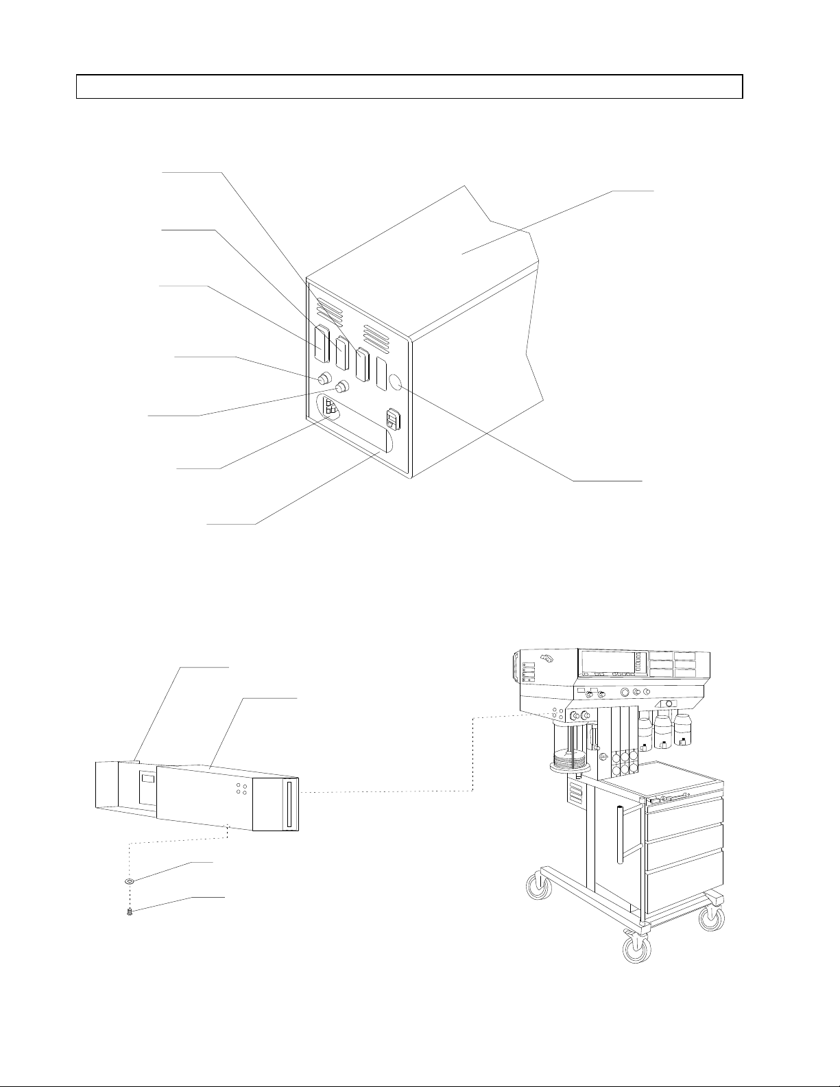
4. UnplugtheACpowercordfromthe
rearoftheORDMCPUassembly.
5. DisconnecttheVitalinkdatacable,
keyboardcableandprintercable(if
applicable)fromtheirportsonthe
rearpaneloftheCPU.
CAUTION: Donotplugorunplugthe
remotedisplaycablewith
powerapplied.
6. Disconnecttheremotedisplaycable
fromitsportontherearpanelof
theCPU.
7. RemovetheCPUretainerscrew
andlockwasherfromtheunderside
oftheCPUhousingasshownin
Figure2.
8. RemovetheCPUassemblyfromthe
housingbygentlyslidingitout
fromtherear.
1
Page 2
RETURN TO SERVICE PROCEDURE TABLE OF CONTENTS
INSTALLATION PROCEDURE (continued)
RETURN TO CD-ROM TABLE OF CONTENTSRETURN TO CD-ROM TABLE OF CONTENTS
PRINTER
PORT
VITALINK
PORT
REMOTE
DISPLAY
PORT
POWER ON
LIGHT
RESET
BUTTON
AC POWER
CONNECTOR
CPU ASSEMBLY
REAR PANEL
SP13201
HOUSING
KEYBOARD
CONNECTOR
Figure 1: 286 CPU REAR PANEL CONNECTIONS
CPU ASSEMBLY
CPU HOUSING
(BOOM ARM
MOUNT NOT SHOWN)
LOCK WASHER
RETAINER
SCREW
SP13202
Figure 2: ORDM CPU HOUSING
2
Page 3
RETURN TO SERVICE PROCEDURE TABLE OF CONTENTS
INSTALLATION PROCEDURE (continued)
RETURN TO CD-ROM TABLE OF CONTENTSRETURN TO CD-ROM TABLE OF CONTENTS
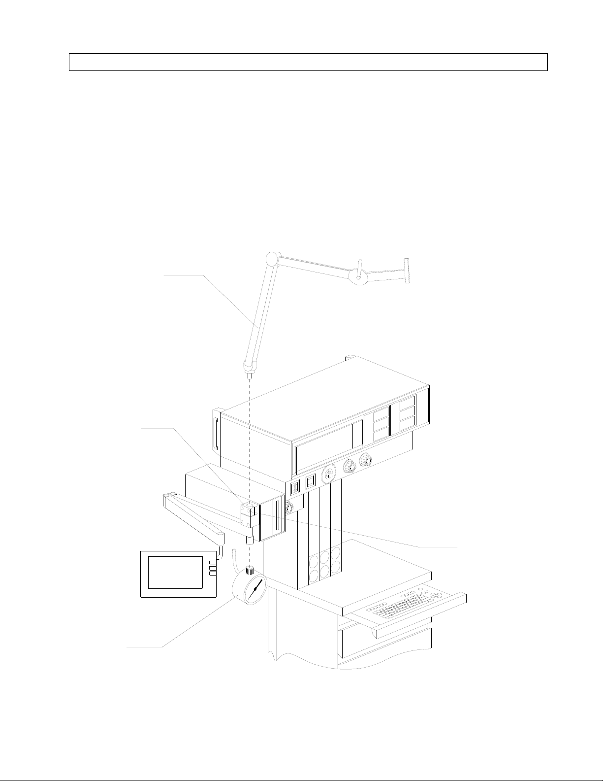
9. If the machine is equipped with a
manual sphygmomanometer,
disconnect the gauge line from the
interface panel. Unscrew the
threaded mounting ring from the
gauge mount and set the gauge
aside.
PATIENT CABLE
BOOM ARM
10. Loosen the clamp screw in the
boom arm mounting block, and
remove the patient cable (upper)
boom arm. See Figure 3.
SP13203
BOOM ARM
MOUNTING
BLOCK
CLAMP SCREW
MANUAL
SPHYGMOMANOMETER
GAUGE
Figure 3: SPHYGMOMANOMETER GAUGE AND UPPER BOOM ARM REMOVAL
3
Page 4
RETURN TO SERVICE PROCEDURE TABLE OF CONTENTS
INSTALLATION PROCEDURE (continued)
RETURN TO CD-ROM TABLE OF CONTENTSRETURN TO CD-ROM TABLE OF CONTENTS
11. Remove the screws securing the
cable clamps to the underside of the
boom arm. Remove the remote
display cable from the clamps.
12. Remove the plastic cap at the end
of the boom arm to expose the
remotedisplaymountingscrew. See
Figure 4.
MOUNTING BLOCK
CLAMP SCREW
1/4-20 x 11/4 in.
MOUNTING BLOCK
SCREWS (3X)
1/4-20 x 1in.
13. While holding the remote display
assembly, loosen the mounting
screw until the assembly separates
from the boom arm. The display
shouldnow be completely separated
from the boom arm.
14. Remove the boom arm assembly
from the ORDM CPU housing by
removing the three boom arm
mounting block screws.
CPU HOUSING
CAP
(DISPLAY
MOUNTING SCREW
RECESS)
SP13204
Figure 4: DISPLAY AND EXISTING BOOM ARM REMOVAL
4
BOOM ARM
MOUNTING BLOCK
DELRIN SPACER
Page 5
RETURN TO SERVICE PROCEDURE TABLE OF CONTENTS
INSTALLATION PROCEDURE (continued)
RETURN TO CD-ROM TABLE OF CONTENTSRETURN TO CD-ROM TABLE OF CONTENTS
15. If the installation includes an
optional patient line boom arm,
remove the existing CPU housing
from the machine and install the
new CPU housing (P/N 4112875).
16. Carefully slide the new 386 CPU
assembly (P/N 4112432) into the
housing and ensure that the disk
drive is correctly aligned with the
front panel opening.
17. Reinstall the retainer screw and
lock washer that was removed in
Step 7.
CAUTION/ SALE
LABEL (P/N 4104294)
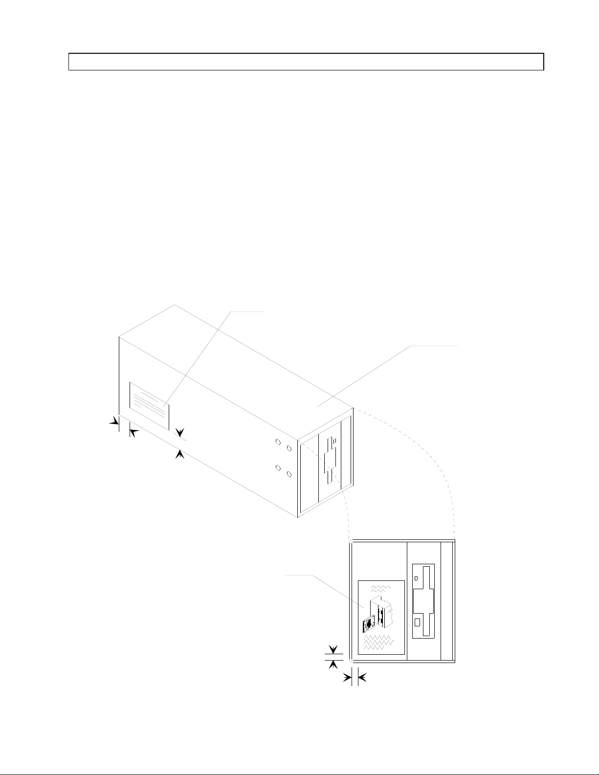
18. Apply the disk insertion label (P/N
4112339) to the front of the CPU
housing, positioned and oriented as
shown in Figure 5. Ensure that the
sticker area is clean, dry and free of
cleaning solution residue.
19. Apply the CAUTION/SALE label
(P/N 4104294) to the side of the
CPU housing as shown in Figure 5.
Ensure that the sticker area is
clean, dry and free of cleaning
solution residue.
CPU HOUSING
1/2 IN.
SP13205
1/2 IN.
DISK INSERTION
LABEL (P/N 4112239)
FRONT VIEW
OF CPU
1/4 IN.
1/4 IN.
Figure 5: PLACEMENT OF LABELS
5
Page 6

RETURN TO SERVICE PROCEDURE TABLE OF CONTENTS
INSTALLATION PROCEDURE (continued)
RETURN TO CD-ROM TABLE OF CONTENTSRETURN TO CD-ROM TABLE OF CONTENTS
NOTE: Steps 21 thru 25 are
performed using the
hardware provided in the
packet supplied with the
adjustable remote arm.
Refer to Figure 6 for these
steps.
19A. If the joint assembly is not pre-
assembled to the display arm,
insert the joint assembly into the
arm and secure it with three 10-32
x in. button head socket screws
(P/N HW09005). See assembly
detail in Figure 6.
20. Install the patient IV line plastic
looms using a 6-32 x in. button
head socket screw (P/N HW09000)
to secure each loom. Apply a small
amount of Loctite #222 (purple) to
the threads of each screw before
installation. (An additional
mounting screw will be installed
through the bottom of each loom
when the Datagrip and display
cables are installed.)
If the patient IV line wire loom block was
pre-assembled to the arm, skip to Step 26.
21. If not already assembled, install a
10-32 x 1 in. socket head cap screw
(wire loom tension adjustment
screw) and 10-32 hex nut in the
wire loom block. Do not tighten the
screw.
Place the ¼ in. flat washer in the
recess in the wire loom block.
22. Insert the block into the arm and
secure it with two 6-32 x in.
button head socket screws through
the bottom of the arm. Apply a
small amount of Loctite #222
(purple) to the threads of each
screw before installation.
23. Insert the patient IV line wire loom
up into the display arm elbow. Turn
the wire loom as needed to align its
tapped hole with the access hole in
the end of the block.
24. Apply a small amount of Loctite
#222 (purple) to the threads of a 632 x ½ in. flat point set screw, and
thread the screw into the hole in
the wire loom until the loom can be
rotated 360° on its axis.
25. Tighten the wire loom tension
adjustment screw until the wire
loom has the desired tension.
6
Page 7

RETURN TO SERVICE PROCEDURE TABLE OF CONTENTS
INSTALLATION PROCEDURE (continued)
ASSEMBLY DETAIL
RETURN TO CD-ROM TABLE OF CONTENTSRETURN TO CD-ROM TABLE OF CONTENTS
JOINT
ASSEMBLY
DISPLAY ARM
PATIENT IV LINE
PLASTIC LOOMS
SET SCREW
WIRE LOOM TENSION
ADJUSTMENT SCREW
PATIENT
IV LINE WIRE LOOM
SP13206
Figure 6: ASSEMBLING THE DISPLAY ARM HARDWARE
7
Page 8
RETURN TO SERVICE PROCEDURE TABLE OF CONTENTS
INSTALLATION PROCEDURE (continued)
RETURN TO CD-ROM TABLE OF CONTENTSRETURN TO CD-ROM TABLE OF CONTENTS
NOTE: Follow Step 26A if the installation
is receiving an optional patient line boom
arm.
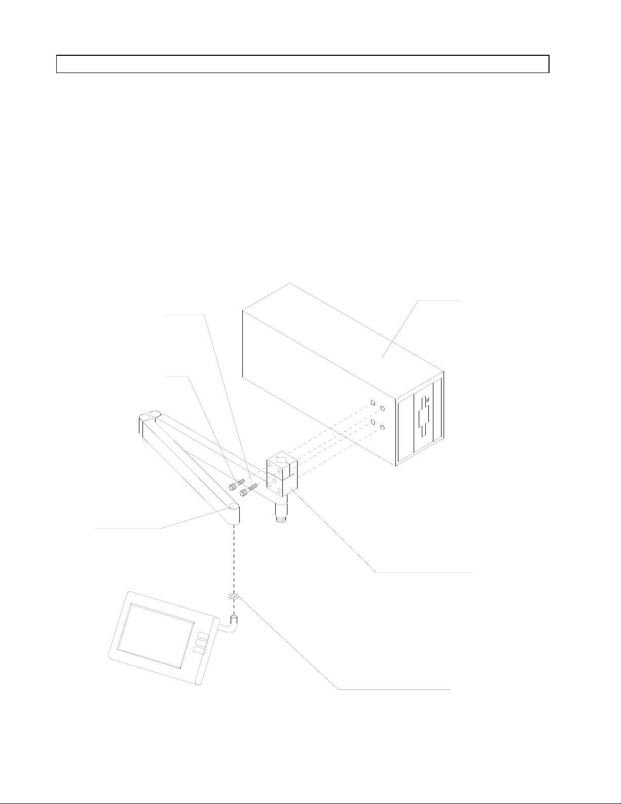
26. If the display arm was not preassembled to the boom arm block,
attach the display arm to the block
with two -24 x 1½ in. socket head
cap screws (P/N HW01101). See
Figure 7.
27. Position the display arm and block
assembly at the left side of the CPU
housing and attach the block to the
housing with three ¼-20 x 1 in.
socket head cap screws (P/N
HW01038).
CPU ASSEMBLY
If the machine is equipped with a
manualsphygmomanometer,attach
the gauge mount to the lower front
corner of the CPU housing with a
¼-20 x 1 in. button head socket
screw.
SP13207
BOOM ARM
BLOCK MOUNTING
SCREWS (3X)
DISPLAY
ARM
Figure 7: DISPLAY ARM INSTALLATION ON OUTBOARD ORDM
CPU HOUSING
THREADED HOLE FOR
CABLE CLAMP SCREW
CPU RETAINER SCREW
AND LOCKWASHER
DISPLAY ARM
MOUNTING SCREWS (2X)
BOOM ARM BLOCK
8
Page 9

RETURN TO SERVICE PROCEDURE TABLE OF CONTENTS
INSTALLATION PROCEDURE (continued)
RETURN TO CD-ROM TABLE OF CONTENTSRETURN TO CD-ROM TABLE OF CONTENTS
26A. If the display arm was not pre-
assembled to the boom arm block,
attach the display arm to the block
with two -24 x 1½ in. socket head
cap screws. See Figure 7A.
27A Position the display arm and block
assembly at the left side of the CPU
housing and attach the block to the
housing with three ¼-20 x 1 in.
socket head cap screws.
CPU ASSEMBLY
If the machine is equipped with a
manualsphygmomanometer,attach
the gauge mount to the lower front
corner of the CPU housing with a
¼-20 x 1 in. button head socket
screw.
BOOM ARM
BLOCK MOUNTING
SCREWS (3X)
DISPLAY
ARM
SP13207A
PATIENT LINE
BOOM ARM
CPU HOUSING
THREADED HOLE FOR
CABLE CLAMP SCREW
CPU RETAINER SCREW
AND LOCKWASHER
DISPLAY ARM
MOUNTING SCREWS (2X)
BOOM ARM BLOCK
Figure 7A: DISPLAY ARM INSTALLATION ON OUTBOARD ORDM WITH OPTIONAL
PATIENT LINE BOOM ARM
9
Page 10

RETURN TO SERVICE PROCEDURE TABLE OF CONTENTS
INSTALLATION PROCEDURE (continued)
RETURN TO CD-ROM TABLE OF CONTENTSRETURN TO CD-ROM TABLE OF CONTENTS
28. Remove the six screws holding the
rear cover of the remote display and
separate the rear cover from the
remote display. Use caution when
separating the cover so that cables
are not pulled from the display.
29. Loosen the remote display clamp
screws. See Figure 8. Remove the
outer retaining ring from the
remote display mounting rod, and
withdraw the rod approx. 3 in. until
the end of the rod clears the first
clamp. Remove the inner retaining
ring and fully withdraw the display
mounting rod.
30. Examine the mounting rod hole in
the remote display cover. If the hole
does not have a notch as shown in
Figure 9, carefully cut or file a in.
wide notch in the cover that will
clear the stop pins on the new
Datagrip display mounting rod.
31. Replace any cracked display
mounting clamps (P/N 4112685-
001) at this time with the extra
clamps provided in the kit.
32. Reinstall the rear cover on the
remote display with the screws that
were previously removed. (Install
the two shorter screws at the
bottom.)
EXISTING
DISPLAY
MOUNTING
ROD (REMOVE)
NOTCH
SP13208
MOUNTING BLOCK (2X)
(P/N 112685-001)
PS1
PS2
J1
J2
J1
J2
CUTAWAY - REAR VIEW OF REMOTE DISPLAY
J3
INNER RETAINING
RING (REMOVE)
OUTER RETAINING
RING (REMOVE)
REAR
COVER
SCREWS (4X)
CLAMP
SCREWS
REAR COVER
SCREWS (2X)
Figure 8: REMOTE DISPLAY DETAILS
10
Page 11

RETURN TO SERVICE PROCEDURE TABLE OF CONTENTS
INSTALLATION PROCEDURE (continued)
RETURN TO CD-ROM TABLE OF CONTENTSRETURN TO CD-ROM TABLE OF CONTENTS
33. Install the Datagrip assembly (P/N
4111907) at the outboard end of the
display arm. See Figure 9. Be sure
the delrin spacer is in place
between the assembly and the
display arm. Tighten the mounting
screw to a torque of 4 foot pounds.
Reinstall the plastic cap at the end
of the arm.
PATIENT IV
LOOM
DETAIL:
CABLES
34. Slide the remote display onto the
Datagrip display mounting rod.
Orient the display with its face
toward the floor so that the stop
pins on the rod will pass through
the slots in the mounting clamps,
and continue sliding the display
into position.
CABLE CLAMP
CAP
(P/N 4111184)
CABLE CLAMPS
(APPROXIMATE
LOCATION)
SP13209
SPACER
(P/N 4110792-064)
REMOTE
DISPLAY
MOUNTING
SCREW
(P/N 4111199-005)
LOCKWASHER
(P/N HW65010)
BEARING
(P/N 4111181)
SPACER
(P/N 4117092-064)
DELRIN SPACER
(P/N 4110792-044)
DATAGRIP
ASSEMBLY
Figure 9: REMOTE DISPLAY/DATAGRIP INSTALLATION
11
Page 12

RETURN TO SERVICE PROCEDURE TABLE OF CONTENTS
INSTALLATION PROCEDURE (continued)
RETURN TO CD-ROM TABLE OF CONTENTSRETURN TO CD-ROM TABLE OF CONTENTS
35. Tighten the mounting clamps
(accessible through clearance holes
in the rear cover) until the remote
display has the desired amount of
friction on the mounting rod.
36. Attach the Datagrip and remote
display cables to the underside of
the arm using three in. plastic
cable clamps and three 6-32 x in.
button head screws as shown in
Figure 9. (The clamps and screws
are included in the hardware kit
supplied with the adjustable arm.)
Slide the cables under the patient
IV line plastic looms (see detail in
Figure 9) and install a 6-32 x in.
button head socket screw through
each loom into the display arm.
37. Attach the cables to the adapter
plate using a in. plastic cable
clamp (P/N 4112300) and 6-32 x
in. button head socket screw (P/N
HW09000). (Ref. Figure 7.)
For installations with a patient line
boom arm, install the cable clamp
screw in the threaded hole in the
CPU housing ref. Figure 7A).
38. Connect the Datagrip and remote
display cables to their ports on the
rear panel of the ORDM CPU
panel. See Figure 10 for port
location and labeling.
39. Pull the release lever on the display
arm and verify that the arm has
full range of motion with no binding
caused by the cables. Position the
cables in their clamps as needed,
and tighten the clamp screws. Coil
excess cable in the bottom loops of
the plastic IV looms.
40. If the machine is equipped with a
manual sphygmomanometer, screw
the threaded mounting ring of the
gauge onto the gauge mount.
REAR VIEW OF
DATAGRIP PORT
REMOTE DISPLAY
PORT
POWER "ON"
INDICATOR
ORDM ON-OFF
SWITCH
AC POWER CONNECTOR
386 ORDM CPU
USE ONLY WITH.ER.FUSES.
250V FUSES.H.ER.FUSES.
DISCONNECT POWER.FUSES.
BEFORE REPLACING FUSES.
100V
120V
220V
240V
Figure 10: 386 ORDM CPU REAR PANEL CONNECTIONS
PRINTER PORT
VITALINK PORT
KEYBOARD
CONNECTOR
NETWORK
CONNECTOR
SP13210
12
Page 13

RETURN TO SERVICE PROCEDURE TABLE OF CONTENTS
INSTALLATION PROCEDURE (continued)
RETURN TO CD-ROM TABLE OF CONTENTSRETURN TO CD-ROM TABLE OF CONTENTS
41. Loosen the friction adjustment
screw on the underside of the
display arm (no more than one
turn). (It may be necessary to raise
or lower the arm to align the screw
with the access hole.) See Figure
11.
42. Raise and release the arm, and
verify that it returns to an
approximately horizontal position.
Lower and release the arm, and
verify that it returns to an
approximately horizontal position.
Contact the NAD Service
Department if the display arm fails
to return to a near-horizontal
position.
43. Slowly re-tighten the friction
adjustment screw until the arm
stays in position when raised or
lowered. (Do not over-tighten the
screw as this will cause the arm to
loose tension in the raised position.)
SP13211
Figure 11: DISPLAY ARM ADJUSTMENT
FRICTION ADJUSTMENT
SCREW ON UNDERSIDE
OF DISPLAY ARM
(USE 7/64 in. HEX WRENCH)
13
Page 14

RETURN TO SERVICE PROCEDURE TABLE OF CONTENTS
INSTALLATION PROCEDURE (continued)
RETURN TO CD-ROM TABLE OF CONTENTSRETURN TO CD-ROM TABLE OF CONTENTS
44. On the rear panel of the ORDM
CPU, check the voltage indicator
window on the AC power connector
assembly and ensure that the unit
is configured for the mains voltage
on which it is to operate. For 100 or
120 volt operation, the index pin
should appear in the 120 V window;
for 220 or 240 volt operation, the
index pin should appear in the 220
V window. See Figure 12.
AC POWER
CONNECTOR
ASSEMBLY
45. If it is necessary to change the
voltageconfiguration, insert asmall
screwdriver at the location shown
in the illustration and pry out the
fuse holder.
46. Remove the jumper card by
grasping it with long nose pliers
and pulling it straight out.
USE ONLY WITH
250V FUSES
DISCONNECT POWER
BEFORE REPLACING FUSES
100V
120V
220V
240V
VOLTAGE
INDICATOR
WINDOWS
PRY OUT
KEY
100/120V
JUMPER
CARD
ORIENTATION
220/240V
INDEX PIN
SP13212
Figure 12: MAINS VOLTAGE SELECTION
14
Page 15

RETURN TO SERVICE PROCEDURE TABLE OF CONTENTS
INSTALLATION PROCEDURE (continued)
RETURN TO CD-ROM TABLE OF CONTENTSRETURN TO CD-ROM TABLE OF CONTENTS
47. Rotate the jumper card so that the
arrow corresponding to the desired
mains voltage (120 for 110 V or 120
V operation, 220 for 220 V or 240 V
operation) is pointing toward the
inside of the AC power connector
assembly. Orient the nylon key so
that it is seated in the notch on the
outside edge of the card with its
index pin facing outward as shown
in Figure 12.
48. Slide the jumper card into the
tracks on the AC power connector
assembly (ensure that the card is
oriented with its markings toward
the left) and press it firmly into its
socket.
49. Ensure that there are two 2.5 A,
250 V fuses in the fuse holder.
50. Install the fuse holder in the AC
power connector assembly. If the
jumper card has been installed
correctly, the index pin on the
nylon key will be visible in the
desired voltage indicator window.
51. Connect the keyboard, Vitalink
data cable and printer cable (if
applicable) to their ports on the
rear of the ORDM CPU panel.
Refer to Figure 10 for port location
and labeling.
52. Plug the AC power cord into the
rear panel of the CPU.
53. Plug the other end of the AC power
cord into the closest AC
convenience receptacle outlet.
54. Plug the system AC power cord into
a live AC receptacle and enable all
circuit breakers.
55. Turn the System Power switch to
ON.
56. Set the ORDM On-Off switch
(located on the rear ORDM CPU
panel) to the ON position.
57. Verify that the green Power "On"
indicator on the rear panel is
lighted, and the self-diagnostics
screen is displayed. Wait until the
ORDM monitor screen is displayed
before proceeding further. If the
screen gets locked into the "Setting
Time to Host" mode, simultaneously
press the CONTROL and D keys on
the keyboard. This will allow the
ORDM to advance to the Monitor
Screen.
15
Page 16

RETURN TO SERVICE PROCEDURE TABLE OF CONTENTS
INSTALLATION PROCEDURE (continued)
RETURN TO CD-ROM TABLE OF CONTENTSRETURN TO CD-ROM TABLE OF CONTENTS
58. Pull out the keyboard and verify
that the EDIT and START/STOP
RECORD keycaps are installed as
shown in Figure 13.
If either of these keycaps are not
present, remove the keyboard cover
and carefully lift off the existing
keycap(s). Press the new keycap(s)
into place. Clean the keyboard
faceplate and install a new
keyboard cover (P/N 4111314).
PATIENT
DRUGS
MONITOR
DATA
1234567890-
QWERT YUIO P
EDIT
CONTROL
SHIFT
ALT
EVENTS NUMERIC GRAPHIC
ASDFGHJKL
ZXCVBNM
CAPS
LOCK
<
,
EDIT KEYCAP
(P/N S010184)
PRINT
RECORD
:
;
>
.
START/
STOP
RECORD
+_)(*&^%$#@!
=
{
[
"
'
?
/
|
\
}
]
SHIFT
START/STOP RECORD
KEYCAP
SELECT
ENTRY
DELETE
ENTRY
BKSPESC
ENTER
STAT
EVENT
ARTIFACTCONFIG
STAT
DRUG
PAGE
(P/N S010183)
SP13213
Figure 13: KEYBOARD LAYOUT WITH CORRECT KEYCAPS
16
Page 17

RETURN TO SERVICE PROCEDURE TABLE OF CONTENTS
RETURN TO CD-ROM TABLE OF CONTENTSRETURN TO CD-ROM TABLE OF CONTENTS
CONFIGURING THE SERIAL I/O PORT TO A NARKOMED 3
1.A Configure the Narkomed 3 serial
port connected to the O.R. Data
Manager (use Port A, B, C or D)
(refer to Narkomed 3 Operator’s
Manual— MONITORING
SYSTEM, Configure Menu)as
follows:
BAUD RATE : 9600
DATA BITS : 8
PARITY : NONE
STOP BITS : 1
PROTOCOL : 03
2.A Press the CONFIG key on the O.R.
Data Manager keyboard to enter the
System Configuration screen on the
remote display. You can also use
the Datagrip to select CONFIG from
the O.R. Data Manager screen
menu.
3.A When the System Configuration
screen is displayed, the cursor will
appear in the first row as shown in
Figure 14A. Press the S key to
select Service functions, or highlight
the choice and press the ENTER
key or the Datagrip trigger.
Figure 14A: SYSTEM CONFIGURATION SCREEN
17
Page 18

RETURN TO SERVICE PROCEDURE TABLE OF CONTENTS
RETURN TO CD-ROM TABLE OF CONTENTSRETURN TO CD-ROM TABLE OF CONTENTS
CONFIGURING THE SERIAL I/O PORT TO A NARKOMED 3 (continued)
4.A Since the Service Functions screen
is intended for NAD service
personnel only, a prompt for the
service password will appear. as
shown in Figure 15A.
Type in the password and press the
ENTER key or the Datagrip trigger.
Figure 15A: PASSWORD SCREEN
18
Page 19

RETURN TO SERVICE PROCEDURE TABLE OF CONTENTS
RETURN TO CD-ROM TABLE OF CONTENTSRETURN TO CD-ROM TABLE OF CONTENTS
CONFIGURING THE SERIAL I/O PORT TO A NARKOMED 3 (continued)
5.A When the NAD Service Functions
screen is displayed, the screen will
display the current
LOCAL/NETWORK configuration
and the current baud rate.
To configure the O.R. Data Manager
as either LOCAL (floppy disk) or
NETWORK, position the cursor on
the Local/Network cell and press the
SELECT ENTRY key or the Datagrip
trigger to bring up a menu that
contains valid choices for this
configuration.
6.A Select the setting by highlighting
the desired choice and pressing the
ENTER key or the Datagrip trigger.
Figure 16A: SERVICE FUNCTIONS SCREEN
19
Page 20

RETURN TO SERVICE PROCEDURE TABLE OF CONTENTS
RETURN TO CD-ROM TABLE OF CONTENTSRETURN TO CD-ROM TABLE OF CONTENTS
CONFIGURING THE SERIAL I/O PORT TO A NARKOMED 3 (continued)
7.A To configure the serial baud rate,
position the cursor on the Serial
Port Baud Rate cell, and press the
SELECT ENTRY key or the Datagrip
trigger to bring up a menu that
contains valid choices for the baud
rate.
8.A Set the serial port baud rate to
9600 by highlighting the choice and
pressing the ENTER key or the
Datagrip trigger.
9.A Press the CONFIG key to return to
the System Configuration screen.
10.A Press the MONITOR key to return
to the monitor screen.
Figure 17A: SERVICE FUNCTIONS SCREEN, BAUD SELECTION
20
Page 21

RETURN TO SERVICE PROCEDURE TABLE OF CONTENTS
RETURN TO CD-ROM TABLE OF CONTENTSRETURN TO CD-ROM TABLE OF CONTENTS
CONFIGURING THE SERIAL I/O PORT TO A NARKOMED 2B
1.B Configure the Narkomed 2B serial
port connected to the O.R. Data
Manager (use Port A only) (refer to
Narkomed 2B Operator’s Manual—
MONITORING SYSTEM, Configure
Menu) as follows:
BAUD RATE : 1200
DATA BITS : 8
PARITY : NONE
STOP BITS : 1
PROTOCOL : VITALINK
2.B Press the CONFIG key on the O.R.
Data Manager keyboard to enter the
System Configuration screen on the
remote display. You can also use
the Datagrip to select CONFIG from
the O.R. Data Manager screen
menu.
3.B When the System Configuration
screen is displayed, the cursor will
appear in the first row as shown in
Figure 14B. Press the S key to
select Service functions, or highlight
the choice and press the ENTER
key or the Datagrip trigger.
Figure 14B: SYSTEM CONFIGURATION SCREEN
21
Page 22

RETURN TO SERVICE PROCEDURE TABLE OF CONTENTS
RETURN TO CD-ROM TABLE OF CONTENTSRETURN TO CD-ROM TABLE OF CONTENTS
CONFIGURING THE SERIAL I/O PORT TO A NARKOMED 2B (continued)
4.B Since the Service Functions screen
is intended for NAD service
personnel only, a prompt for the
service password will appear. as
shown in Figure 15B.
Type in the password and press the
ENTER key or the Datagrip trigger.
Figure 15B: PASSWORD SCREEN
22
Page 23

RETURN TO SERVICE PROCEDURE TABLE OF CONTENTS
RETURN TO CD-ROM TABLE OF CONTENTSRETURN TO CD-ROM TABLE OF CONTENTS
CONFIGURING THE SERIAL I/O PORT TO A NARKOMED 2B (continued)
5.B When the NAD Service Functions
screen is displayed, the screen will
display the current
LOCAL/NETWORK configuration
and the current baud rate.
To configure the O.R. Data Manager
as either LOCAL (floppy disk) or
NETWORK, position the cursor on
the Local/Network cell and press the
SELECT ENTRY key or the Datagrip
trigger to bring up a menu that
contains valid choices for this
configuration.
6.B Select the setting by highlighting
the desired choice and pressing the
ENTER key or the Datagrip trigger.
Figure 16B: SERVICE FUNCTIONS SCREEN
23
Page 24

RETURN TO SERVICE PROCEDURE TABLE OF CONTENTS
RETURN TO CD-ROM TABLE OF CONTENTSRETURN TO CD-ROM TABLE OF CONTENTS
CONFIGURING THE SERIAL I/O PORT TO A NARKOMED 2B (continued)
7.B To configure the serial baud rate,
position the cursor on the Serial
Port Baud Rate cell, and press the
SELECT ENTRY key or the Datagrip
trigger to bring up a menu that
contains valid choices for the baud
rate.
8.B Set the serial port baud rate to
1200 by highlighting the choice and
pressing the ENTER key or the
Datagrip trigger.
9.B Press the CONFIG key to return to
the System Configuration screen.
10.B Press the MONITOR key to return
to the monitor screen.
Figure 17B: SERVICE FUNCTIONS SCREEN, BAUD SELECTION
24
Page 25

ORDM TEST
RETURN TO SERVICE PROCEDURE TABLE OF CONTENTS
RETURN TO CD-ROM TABLE OF CONTENTSRETURN TO CD-ROM TABLE OF CONTENTS
1. On the ORDM keyboard, press and
hold the ALT key, and press the V
key.
The window shown in Figure 18
will appear at the center of the
remote display for approximately
three seconds. The current software
version number shown on the
remote display should agree with
that marked on the program disk or
its accompanying documentation.
2. Verify the operation of the Datagrip
by pulling the trigger and observing
the menu screen. Use the
thumbwheel to move the cursor in
the menu screen.
3. Ensure that an updated copy of the
ORDM Operator’s Manual (P/N
4111342-006 or later) accompanies
the machine.
4. Perform a complete PMS procedure
on the machine.
ORDM S/W Ver x.x (xxxxH)
Figure 18: SOFTWARE VERSION WINDOW
25
Page 26

NORTH
AMERICAN
DRÄGER
Technical Service Department
3122 Commerce Drive
Telford, PA 18969
(215) 721-5402
(800) 543-5047
(215) 723-5935 Fax
RETURN TO SERVICE PROCEDURE TABLE OF CONTENTS
RETURN TO CD-ROM TABLE OF CONTENTSRETURN TO CD-ROM TABLE OF CONTENTS
®
Quality Service for Life
Part Number: SP00132
Rev: E
Date: February 15, 1995
© 1995 N.A.D., Inc.
 Loading...