

Page 1

Nortel WLAN - Security Switch 2300 Series Quick Start Guide
Nortel WLAN—Security Switch 2300 Series
Document number: NN47250-300
Document status: Standard
Document version: 02.01
Part Code: 320655-E
Release Date: October 2007
Page 2

2
Copyright © 2007 Nortel Networks. All rights reserved.
The information in this document is subject to change without notice. The statements, configurations, technical data, and recommendations in this document are believed to be accurate and reliable, but are presented without express or implied warranty.
Users must take full responsibility for their applications of any products specified in this document. The information in this
document is proprietary to Nortel Networks.
Trademarks
*Nortel, Nortel Networks, the Nortel logo, and the Globemark are trademarks of Nortel Networks.
All other products or services may be trademarks, registered trademarks, service marks, or registered service marks of their
respective owners.
The asterisk after a name denotes a trademarked item.
International Regulatory Statements of Conformity for the WSSs
This is to certify that the Nortel WLAN Security Switch 2300 series switches are evaluated to the international regulatory standards for electromagnetic compliance (EMC) and safety and was found to have met the requirements for the following international standards:
• EMC - Electromagnetic Emissions – CISPR 22, Class A
• EMC - Electromagnetic Immunity – CISPR 24
• Electrical Safety – IEC 60950, with CB member national deviations
• Further, the equipment has been certified as compliant with the national standards as detailed below.
National Electromagnetic Compliance (EMC) Statements of Compliance
FCC statement (USA only)
This equipment has been tested and found to comply with the limits for a Class A digital device, pursuant to Part 15
of the Federal Communications Commission (FCC) rules. These limits are designed to provide reasonable protection
against harmful interference when the equipment is operated in a commercial environment. This equipment
generates, uses, and can radiate radio frequency energy. If it is not installed and used in accordance with the
instruction manual, it may cause harmful interference to radio communications. Operation of this equipment in a
residential area is likely to cause harmful interference, in which case users will be required to take whatever measures
may be necessary to correct the interference at their own expense.
ICES statement (Canada only)
Canadian Department of Communications Radio Interference Regulations
This digital apparatus (WLAN Security Switch 2300 series switches) does not exceed the Class A limits for
radio-noise emissions from digital apparatus as set out in the Radio Interference Regulations of the Canadian
Department of Communications.
Règlement sur le brouillage radioélectrique du ministère des
Communications
Cet appareil numérique (WLAN Sécurité Changement 2300 changements de la série) respecte les limites de
bruits radioélectriques visant les appareils numériques de classe A prescrites dans le Règlement sur le brouillage
radioélectrique du ministère des Communications du Canada.
CE marking statement (Europe only)
EN 55022 statements
This is to certify that the Nortel WLAN Security Switch 2300 Series switches are shielded against the
generation of radio interference in accordance with the application of Council Directive 89/336/EEC.
Conformity is declared by the application of EN 55022 Class A (CISPR 22).
War nin g: This is a Class A product. In a domestic environment, this product may cause radio interference,
in which case, the user may be required to take appropriate measures.
Achtung: Dieses ist ein Gerät der Funkstörgrenzwertklasse A. In Wohnbereichen können bei Betrieb
dieses Gerätes Rundfunkstörungen auftreten, in welchen Fällen der Benutzer für entsprechende
Gegenmaßnahmen verantwortlich ist.
NN47250-300 (320655-E Version 02.01)
Page 3
Attention: Ceci est un produit de Classe A. Dans un environnement domestique, ce produit risque de créer
des interférences radioélectriques, il appartiendra alors à l’utilisateur de prendre les mesures spécifiques
appropriées.
EN 55024 statement
This is to certify that the Nortel WLAN Security Switch 2300 Series switches are shielded against the susceptibility to radio interference in accordance with the application of Council Directive 89/336/EEC. Conformity is
declared by the application of EN 55024 (CISPR 24).
European Union and European Free Trade Association (EFTA) notice
All products labeled with the CE marking comply with the Electromagnetic Compliance (EMC) Directive
(89/336/EEC) and the Low Voltage Directive (73/336/EEC) issued by the Commission of the European
Community.
3
equivalent international standards are listed in parenthesis.
• EN 55022 (CISPR 22)–Electromagnetic Interference
• EN 55024 (IEC 61000-4-2, -3, -4, -5, -6, -8, -11)–Electromagnetic Immunity
• EN 61000-3-2 (IEC 610000-3-2)–Power Line Harmonics
• EN 61000-3-3 (IEC 610000-3-3)–Power Line Flicker
Compliance with these directives implies comformity to the following European Norms (ENs). The
VCCI statement (Japan/Nippon only)
This is a Class A product based on the standard of the Voluntary Control Council for Interference (VCCI) for
information technology equipment. If this equipment is used in a domestic environment, radio disturbance may arise.
When such trouble occurs, the user may be required to take corrective actions.
BSMI statement for Nortel WLAN Security Switch 2300 Series switches (Taiwan only)
This is a Class A product based on the standard of the Bureau of Standards, Metrology and Inspection (BSMI) CNS
13438, Class A.
MIC notice (Republic of Korea only)
This device has been approved for use in Business applications only per the Class A requirements of the Republic of
Korea Ministry of Information and Communications (MIC). This device may not be sold for use in a non-business
application.
Observe the Regulatory Marking label on the back or bottom of each switch for specific certification information
pertaining to this model. Each model in the WLAN Security Switch 2300 Series is approved for shipment to/usage in
Korea and is labeled as such, with all appropriate text and the appropriate MIC reference number.
Nortel WLAN - Security Switch 2300 Series Quick Start Guide
Page 4

4
National Safety Statements of Compliance
EN 60950 statement
This is to certify that the Nortel WLAN Security Switch 2300 Series switches are in compliance with the
requirements of EN 60950 in accordance with the Low Voltage Directive. Additional national differences for all
European Union countries have been evaluated for compliance.
NOM statement (Mexico only)
The following information is provided on the devices described in this document in compliance with the safety
requirements of the Norma Oficial Méxicana (NOM):
Exporter: Nortel Networks
4655 Great America Parkway
Santa Clara CA 95054 USA
Importer: Nortel Networks de México, S.A. de C.V.
Avenida Insurgentes Sur #1605
Piso 30, Oficina
Col. San Jose Insurgentes
Deleg-Benito Juarez
México D.F. 03900
Tel: 52 5 480 2100
Fax: 52 5 480 2199
Input Model 2350 (with external power supply)
48V dc, 830mA, 40W
External Power Supply AC Input
100-240V ac, 50-60Hz, 1.0A
Input Model 2360 (single power supply)
100-240V ac, 50-60Hz, 2.0A
Model 2361 (with redundant supply)
100-240V ac, 50-60Hz, 2.0A
Input Model 2380 (single power supply)
100-240V ac, 50-60Hz, 8.0/3.5A
Model 2380 (with redundant supply)
100-240V ac, 50-60Hz, 8.0/3.5A
Input Model 2382 (with redundant supply)
100-240V ac, 50-60Hz, 1.0/0.5A
Información NOM (unicamente para México)
La información siguiente se proporciona en el dispositivo o en los dispositivos descritos en este documento, en
cumplimiento con los requisitos de la Norma Oficial Méxicana (NOM):
Exportador: Nortel Networks
4655 Great America Parkway
Santa Clara, CA 95054 USA
Importador:Nortel Networks de México, S.A. de C.V
NN47250-300 (320655-E Version 02.01)
Page 5
Importador: Nortel Networks de México, S.A. de C.V.
Avenida Insurgentes Sur #1605
Piso 30, Oficina
Col. San Jose Insurgentes
Deleg-Benito Juarez
México D.F. 03900
Tel: 52 5 480 2100
Fax: 52 5 480 2199
Entrada Modele 2350 (con suministro de corriente externo)
48V CC, 830mA, 40W
AC el suministro de Power externo
100-240V CA, 50-60Hz, 1,0A
Entrada Modele 2360 (solo suministro de corriente)
100-240V CA, 50-60Hz, 2,0A
Modele 2361 (con suministro redundante)
100-240V CA, 50-60Hz, 2,0A
Entrada Modele 2380 (solo suministro de corriente)
100-240V CA, 50-60Hz, 8,0/3,5A
Modele 2380 (con suministro redundante)
100-240V CA, 50-60Hz, 8,0/3,5A
5
Entrada Modele 2382 (con suministro redundante)
100-240V CA, 50-60Hz, 1,0/0,5A
Denan Statement (Japan/Nippon only)
Nortel WLAN - Security Switch 2300 Series Quick Start Guide
Page 6

6
NN47250-300 (320655-E Version 02.01)
Page 7

Contents
This document contains the following information:
•
Introduction (page 9)
— Audience (page 9)
— How to get help (page 9)
— Precautions (page 10)
• Preventing electrostatic damage in new cable installations (page 11)
— Planning a WLAN installation (page 13)
— Gathering required information (page 14)
— Preventing electrostatic discharge damage (page 10)
• Quick Start — Physical Installation (page 15)
— Installing the Nortel WLAN Security Switch (page 15)
— Installing a new power supply (page 17)
— Powering on the Nortel WLAN Security Switch (page 17)
— Powering on a 2382 (page 18)
— Connecting to the network (page 19)
• Quick Start — Basic Configuration (page 23)
— WSS startup algorithm (page 23)
— WSS sample network configuration (page 24)
— Configuring the Nortel WLAN Security Switch (page 24)
— Creating a scope on the DHCP server (page 25)
— Accessing the WSS CLI quickstart wizard (page 26)
— Installing and using WMS (page 28)
— Configuring WSS using WMS (page 31)
— Test the solution (page 35)
— Where to go next (page 35)
7
Nortel WLAN - Security Switch 2300 Series Quick Start Guide
Page 8

8
NN47250-300 (320655-E Version 02.01)
Page 9

Introduction
This Quickstart Guide provides basic instructions on how to install the hardware and perform basic configuration of a
Nortel WLAN Security Switch (WSS).
Audience
The Quickstart Guide is intended for experienced installers.
How to get help
This section explains how to get help for Nortel products and services.
Finding the latest updates on the Nortel web site
The content of this documentation was current at the time the product was released. To check for updates or receive
technical support for Nortel products, check the Nortel Technical Support web site:
http://www.nortel.com/support
This site provides quick access to software, documentation, bulletins, and tools to address issues with Nortel
products. From this site, you can:
• download software, documentation, and product bulletins
• search the Technical Support Web site and the Nortel Knowledge Base for answers to technical issues
• sign up for automatic notification of new software and documentation for Nortel equipment
• open and manage technical support cases
Getting help over the phone from a Nortel Solutions Center
9
If you do not find the information you require on the Nortel Technical Support web site, and you have a Nortel
support contract, you can also get help over the phone from a Nortel Solutions Center.
In North America, call 1-800-4NORTEL (1-800-466-7835).
Outside North America, go to the following web site to obtain the phone number for your region:
http://www.nortel.com/callus
Getting help from a specialist by using an Express Routing Code
To access some Nortel Technical Solutions Centers, you can use an Express Routing Code (ERC) to quickly route
your call to a specialist in your Nortel product or service. To locate the ERC for your product or service, go to:
http://www.nortel.com/erc
Getting help through a Nortel distributor or reseller
If you purchased a service contract for your Nortel product from a distributor or authorized reseller, contact the
technical support staff for that distributor or reseller.
Nortel WLAN - Security Switch 2300 Series Quick Start Guide
Page 10
10
Precautions
Protecting cables and connectors
• Support cables in order to prevent any stress on the connectors. If you have a high cable density configuration,
you need to install additional cable management equipment.
• Do not exceed the bend radius recommended for the type of cable installed.
• Fiber optic cables and connectors require special care.
• Protect connectors with rubber safety plugs when cables are not inserted.
• When installing or replacing cables, follow appropriate fiber-cleaning procedures.
• Do not exceed the bend radius recommended for fiber optic cable. The acceptable bend radius for fiber optic
cable is ten times its diameter, or between 2.5 and 5 cm (1 to 2 in.). Anything less than the recommendation can
cause a loss of integrity of data transmission. Loss of integrity because of incorrect bend radius is difficult to
diagnose.
WARNING
Installation must be performed by qualified service personnel only. Read and
follow all warning notices and instructions marked on the product or included
in the documentation. Before installing the product, read Translated caution
statements, warning conventions and warning messages (page 36).
Preventing electrostatic discharge damage
Electrostatic discharge (ESD) is a discharge of stored static electricity that can damage equipment and impair
electrical circuitry. These electrostatic voltages can result from friction, including, but not exclusive to, pulling
cabling through conduits, walking across carpeted areas, and building up of static charge in clothing. ESD damage
occurs when electronic components are improperly handled and can result in complete or intermittent failures.
While networking equipment is commonly designed and tested to withstand common mode ESD events, voltage
sometimes can be discharged to some connector pins but not others, or to some pins before others, which has the
potential to damage the networking equipment.
To protect Nortel equipment against ESD damage, take the following preventive measures before connecting any data
cables to the device:
• Always use anti-static wrist straps. Make sure the strap is adjusted to provide good skin contact.
• Ensure that work surfaces and equipment racks are properly grounded for protection against electrostatic
discharge. The common point must be connected to the building ground wire. In a properly wired building, the
nearest reliable ground is typically at the electrical outlet.
• Avoid contact between equipment and clothing. The wrist or ankle strap only protects the equipment from ESD
voltages on the body; ESD voltages on clothing can still cause damage.
• Avoid touching any connector pins.
• Do not remove the wrist or ankle strap until the installation is complete.
NN47250-300 (320655-E Version 02.01)
Page 11
11
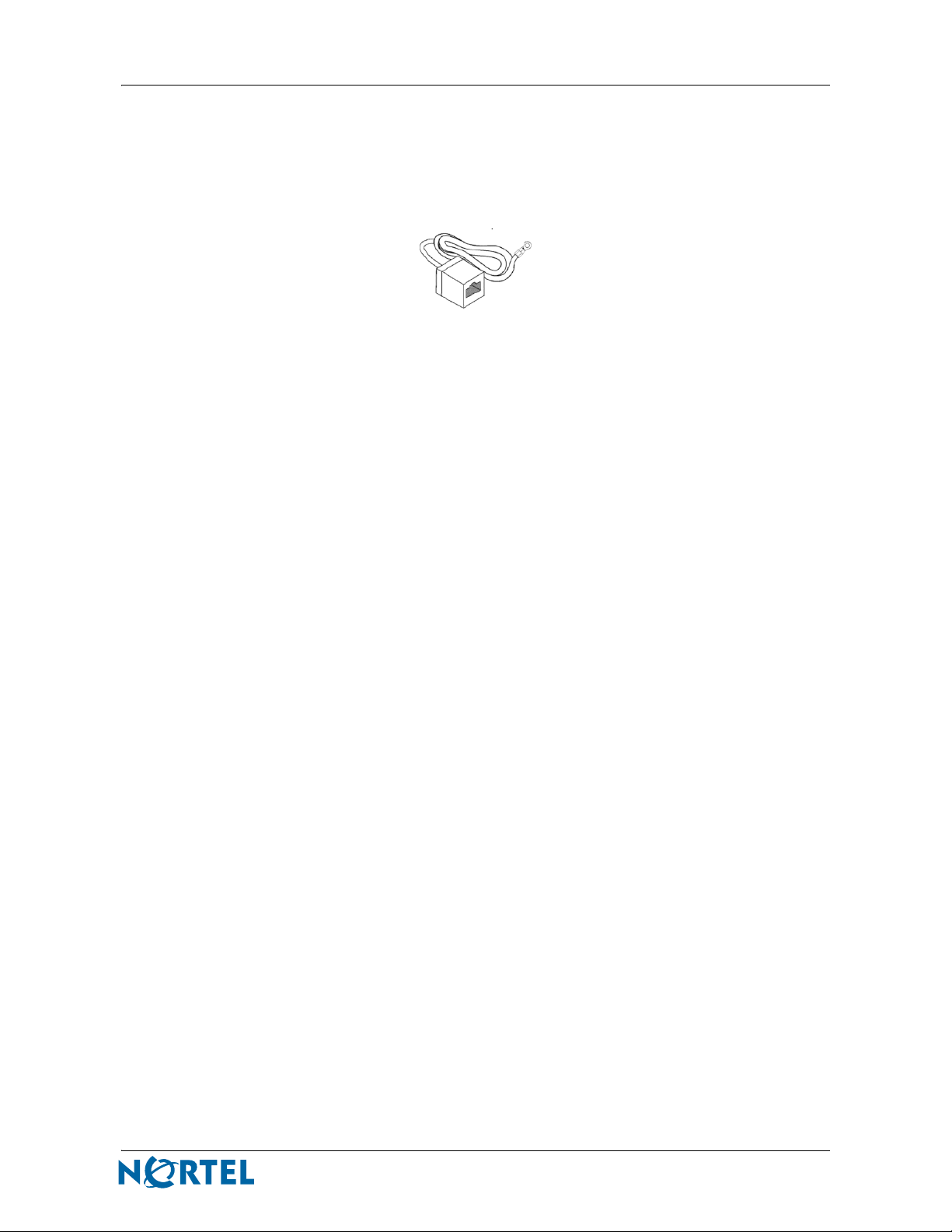
Preventing electrostatic damage in new cable installations
With new cable installations, Nortel recommends to use ESD discharge cable to reduce the potential for damage from
static that can build up in cables. An example of such a cable is illustrated below.
Figure 1: ESD Cable example
Step - Action
1 Connect the ground lug on the ESD discharge cable to a safe and suitable
earth ground.
2 Briefly connect all RJ-45 cable connectors to the female RJ-45 connector of
the ESD discharge cable, and then connect each RJ-45 cable connector to
the switch.
3 Leave cables connected to the networking equipment. Once cables are
connected to networking equipment, the cables do not build up charge.
Nortel WLAN - Security Switch 2300 Series Quick Start Guide
Page 12

12
NN47250-300 (320655-E Version 02.01)
Page 13

Before you begin
Before installing and configuring the WSS, the following basic planning steps must be completed.
Planning a WLAN installation
The WLAN Management Software (WMS) can only be installed on a single computer. You must decide which
computer will be used to manage the WSS, and ensure that computer is accessible during the installation and
configuration process.
The WMS installation CD is distributed with a license certificate to specify the serial number and Nortel Support
email address. An email request must be sent to Nortel Support to receive the WMS license activation key as follows:
• WMS serial number — This serial number is listed on the license certificate included with the WMS CD.
• computer name — The computer name where WMS will be installed.
• company name — The name of your company.
A license activation key is required to use WMS, and must be available before you begin to configure the WSS.
When planning to install a wireless Access Point (AP), be sure to record the model and serial number printed on the
back of the AP. This information is required when configuring WSS ports and Access Points (AP) using WMS. If the
AP is already physically installed in a difficult to access location, the model and serial numbers are also printed on
the box used to deliver the AP.
Some additional basic network information is also required before WMS configuration takes place, as described in
“Gathering required information” on page 14.
13
Nortel WLAN - Security Switch 2300 Series Quick Start Guide
Page 14
14
Gathering required information
Before installing or configuring the WSS, print a copy of this page and ensure that all value fields in Table 1 have
been filled in correctly. Keep this information close by during the configuration process.
Table 1: Required information
Information Description Values
Computer name Each WMS license is limited to a single computer.
WMS serial number The WMS serial number and instructions for
WMS license key The WMS license activation key must be received
IP subnet address The IP subnet address of the WLAN 2300 System.
DNS server IP address The IP address of the DNS server.
Domain name The domain name where the WLAN 2300 System is
AP model number The AP model that is being used in your WLAN
AP serial number Each AP has a unique serial number on the bottom of
obtaining a license key are included on a sheet of
paper inside the WSS box.
from Nortel.
located.
2300 System.
the AP. This serial number is required when
configuring the WSS.
NN47250-300 (320655-E Version 02.01)
Page 15

Quick Start — Physical Installation
This section describes how to physically install a WSS. For more information about physical installation, see Nortel
WLAN—Security Switch 2300 Series Installation and Basic Configuration Guide.
Installing the Nortel WLAN Security Switch
Estimated timing: 10 minutes
A WSS can be installed on either a tabletop surface or in an equipment rack. Tab le 2 outlines which installation
methods are available for each WSS model.
Table 2: Installation methods
WSS model Tabletop Front-mount rack Center-mount rack
2350 X
2360/2361 X X
2380 X X X
2382 X X X
When choosing a location for the WSS, ensure that:
15
• The power outlet is within 1.82 m (6 ft) of the device.
• There is proper heat dissipation from and adequate ventilation around the
switch.
Tabletop Installation
Step Action
1 Ensure that the table surface supports at least 3 kg (6.6 lb).
2 Carefully turn the WSS upside down on a clean work surface with no debris.
3 Wipe the four placement locations for the rubber feet to clear away any oil or dust.
Each location area is marked with an ‘X’.
4 Attach the four rubber adhesive feet over the ‘X’s.
5 Turn the WSS right-side up, and place the switch in position on the table.
Equipment Rack Installation
Step Action
1 Remove the four bracket screws from each side of the WSS.
2 Align a bracket over the screw holes:
• For a front-mount equipment rack, align the bracket so that the bracket flange is
flush with the WSS front panel and away from the switch.
• For a center-mount equipment rack, align the bracket so that the bracket flange
is located near the center screw holes, as shown in Figure 2.
End
Nortel WLAN - Security Switch 2300 Series Quick Start Guide
Page 16

16
Figure 2: 2380 Installation—Center-Mount Equipment Rack
First, attach brackets to chassis.
le
so
on
C
st
R
Console
t
s
R
Then, install chassis into rack.
840-9502-0057
3 Reinsert the screws to secure the brackets to the WSS.
4 Repeat for the other bracket.
CAUTION
Nortel recommends that you ask someone to assist you with the
remaining steps. If you accidentally drop the WSS, you can be injured
and the switch can be damaged.
5 Lift the WSS into position in the equipment rack.
6 Insert the bottom rack-mount screws into the bracket flanges to secure the WSS to the
equipment rack, then insert the top screws.
End
NN47250-300 (320655-E Version 02.01)
Page 17

Installing a new power supply
Estimated timing: 5 minutes
Some WSS models support secondary power supplies. To install a secondary power supply, complete the following
steps:
Step Action
1 Loosen the thumbscrew in an unused slot with a #2 Phillips-head screwdriver, and
remove the cover plate.
2 Remove the new power supply from its packaging and lift the supply by grasping the
front handle with one hand and supporting the supply from the bottom with the other
hand.
3 Insert the power supply into the slot as shown in Figure 3, pushing gently but firmly until
the supply is fully seated and flush with the switch’s front panel.
Figure 3: Inserting a Power Supply in a 2380 Switch
17
4 Tighten the thumbscrew using a #2 Phillips-head screwdriver.
End
Powering on the Nortel WLAN Security Switch
Estimated timing: 5 minutes
Powering on a 2350
Step Action
1 Plug the external power supply input AC cord into an AC pow er source.
2 Attach the external power supply DC output cable to the Power port on the 2350 .
The 2350 begins booting as soon as you plug in the power cord.
3 Ensure that the external power supply LED and the 2350 power LED turn green to
verify that the external power supply is operating normally.
840-9502-0060
End
Nortel WLAN - Security Switch 2300 Series Quick Start Guide
Page 18

18
Powering on a 2360/2361
Step ActionStep
1 Attach the approved AC power cord to each Power port on the 2360 or 2361 (2 power
ports).
2 Plug the power cord (s) into the AC powe r source (s).
The 2360 or 2361 begins booting as soon as you plug in the power cord(s).
3 On the 2360 ensure that the power supply LED turns green to verify that the power
supply is operating normally. On the 2361 observe each power supply. LED to verify
that both power supplies are operating normally.
Powering on a 2380
Step Action
1 Ensure that any removable power supply is fully seated in the 2380.
2 For each power supply that you are using on the 2380, attach a power cord.
3 Plug each power cord into an AC power source.
The 2380 begins booting as soon as you plug in the power cord(s).
4 On each 2380 power supply ensure that the power LED turns green to verify that the
power supply is operating normally. For the 2380 switch, wait a few seconds to verify
that the Mgmt LED is functioning (repeatedly flashing bright green, then fading).
Powering on a 2382
Note: The WSS 2382 runs only on Version 6.0 software and later releases.
Software Versions prior to 6.0 will not run on this hardware.
Step Action
1 Ensure that any removable power supply is fully seated in the 2382.
2 For each power supply that you are using on the 2382, attach a power cord.
3 Plug each power cord into an AC power source.
The 2382 begins booting as soon as you plug in the power cord(s).
4 On each 2382 power supply ensure that the power LED turns green to verify that the
power supply is operating normally. For the 2382 switch, wait a few seconds to verify
that the Mgmt LED is functioning (repeatedly flashing bright green, then fading).
End
End
NN47250-300 (320655-E Version 02.01)
Page 19

Connecting to a Serial Management Console
Estimated timing: 5 minutes
Step Action
1 Insert the serial cable into the PC port.
2 Insert the other end of the cable into the serial console port on the WSS.
3 Start a standard VT100 terminal emulation application on the PC, and configure the
modem settings listed in Table 3.
Table 3: Communication protocol settings
Setting Value
Baud rate 9600 bps
Data bits 8 bits
Stop bits 1 stop
Parity No parity
Flow Control off or disabled
19
4 Open a terminal connection on a serial port.
If the WSS is already powered on, then the terminal connection will request a
password. Leave the password field blank, because the default password is not set.
5 Press Enter until the command prompt appears.
Connecting to the network
Estimated timing: 5 minutes
Connecting Access Points
Use the following procedure to connect a AP to the WSS or to another PoE-capable 10/100 ethernet device. For
information about the physical installation of APs, see Nortel WLAN—Access Point 2330A/2330B Quick Installation
Guide or Nortel WLAN—Series 2332 Access Point Quick Installation Guide.
Step Action
1 Connect an ethernet cable to the AP.
2 Connect the other end of the ethernet cable to the WSS port, or to the ethernet device.
• If connecting the AP to the WSS, the AP will not receive power until PoE is
enabled for that port.
End
Nortel WLAN - Security Switch 2300 Series Quick Start Guide
Page 20

20
• If connecting the AP to an ethernet device other than the WSS, observe the
appearance of the AP LED for the port.
Tab le 4 describes the AP LED appearance and associated meaning.
Table 4: AP LED indicator status
AP LED Appearance Meaning
Solid green For an AP active link, with PoE enabled, the following are
Alternating green and amber AP is booting with an image received from the WSS.
Solid amber PoE is enabled, but the AP is not connected to the network.
Blinking amber AP is unresponsive or there is a PoE problem.
Unlit PoE is disabled.
true:
• AP has booted. AP has received a valid configuration
from the WSS.
• Management link with an AP is operational.
• For an AP’s secondary link, the link is present.
End
Connecting other ethernet network devices
Use the following procedure to connect a WSS to other 10/100 Ethernet devices, or a gigabit Ethernet device.
Step Action
1 Insert a Cat-5 cable with a standard RJ-45 con nector.
• Use a straight-through cable to connect to a router, Access Point (AP), or an end
station such as a PC, printer, or server.
• Use a crossover cable to connect to another switch.
Note: The 10/100 Ethernet por ts on 2360/2361 switches provide au tomatic
MDI/MDX.
2 If the cable is attached to a wired end station that uses AAA through the WSS to
access the network, set the port type for a wired authentication port to activate the link.
NN47250-300 (320655-E Version 02.01)
Page 21

3 Observe the appe arance of the Link LED for the port to determine link status.
Tab le 5 describes the LED appearance, and what each appearance means. If the Link LED is unlit, check the cable
connection and verify that the device at the other end of the link is operating.
Table 5: Link LED indicator status
Link LED Appearance Meaning
Solid green 100-Mbps link is operational.
Solid amber 10-Mbps link is operational.
Blinking green Traffic is active on the 100-Mbps link.
Blinking amber Traffic is active on the 10-Mbps link.
Unlit Link is not operational.
Verify that the device at the other end of the link is operating.
End
Connecting to fiber gigabit devices (WSS 2380 and WSS 2382 only)
You must install a gigabit interface converter (GBIC) to connect the WSS 2380/2382 using 1000BASE-SX or
1000BASE-LX fiber cables. Complete the following procedure to install a GBIC and connect the fiber cable.
21
Step Action
1 Insert the GBIC into a GBIC slot on the front panel until it clicks into place.
2 Remove the protective covering(s) from the port connector(s) and set them aside in a
safe place for later use.
3 Insert the network cable.
Note: For 1000BASE-SX or 1000BASE-LX fiber, make sure you insert the
two cable ends in the proper sides (transmit or receive). Othe rwise, the link
does not work.
4 Observe the uppe r LED to the right of the GBIC port:
• If the LED is green, the 1000-Mbps link is operational.
• If the LED is blinking amber, traffic is active on the 1000-Mbps link.
• If the LED is unlit, the link is not operational. Check the cable and verify that the
device at the other end of the link is operational.
End
Nortel WLAN - Security Switch 2300 Series Quick Start Guide
Page 22

22
Connecting to copper gigabit devices (WSS 2380 and WSS 2382 only)
Complete the following procedure to install a GBIC.
Step Action
1 Insert a Cat-5 cable with a standard RJ-45 connector into the port’s copper interface.
The Cat-5 cable can use straight-through or crossover signa ling.
2 Access the WSS CLI using the serial console port, as described in “Powering on a
2380” on page 18.
3 Enter enable to access the configuration level of the CLI.
The password to gain access to privileged mode is not set. When prompted for the
password, press Enter to continue.
4 Enter set port media-typ e <port-list> rj45 to set the active interface on the port to
RJ-45 (copper).
5 Observe the lower LED to the left of the port:
• If the LED is solid green, the 1000-Mbps link is operational.
• If the LED is blinking green, traffic is active on the 1000-Mbps link.
• If the LED is unlit, the link is not operational. Check the cable and verify that the
device at the other end of the link is operational.
End
NN47250-300 (320655-E Version 02.01)
Page 23

Quick Start — Basic Configuration
This section describes how to configure the WSS. For additional information about configuring your WSS, see the
following documents:
Nortel WLAN—Security Switch 2300 Series Installation and Basic Configuration Guide
Nortel WLAN Security Switch 2300 Series Configuration Guide.
WSS startup algorithm
Figure 4 shows how the WSS Startup Algorithm process is followed when a WSS is powered on.
Figure 4: WSS Startup Algorithm
23
Nortel WLAN - Security Switch 2300 Series Quick Start Guide
Page 24

24
WSS sample network configuration
Figure 5 shows a sample network configuration using a WSS and two APs.
Figure 5: Network diagram
Configuring the Nortel WLAN Security Switch
The steps involved in configuring the solution shown in the diagram can be broken down into the following tasks:
Table 6: Configuration tasks
Task Page
Creating a scope on the DHCP server page 25
Accessing the WSS CLI quickstart wizard page 26
Installing and using WMS page 28
Configuring WSS using WMS page 31
Test the solution page 35
Where to go next page 35
NN47250-300 (320655-E Version 02.01)
Page 25

Creating a scope on the DHCP server
Estimated timing: 10 minutes
If required, create a scope on the DHCP server that will lease addresses to the AP and the mobiles, as shown in
Figure 6.
Figure 6: Creating a DHCP scope
No special scope options need to be configured when the WSS is deployed in layer 2 environments, as the AP will
find the WSS automatically using broadcast.
25
Configuring DHCP for APs
The DHCP option 43 field provides a simple and effective way for APs to find WSSs across an intermediate Layer 3
network. You can use the DHCP option 43 field to provide a list of WSS IP addresses without the need to configure
DNS servers.
To use DHCP option 43, configure the option to contain a comma-separated list of WSS IP addresses or hostnames,
in the following format:
ip:ip-addr1,ip-addr2,...
or
host:hostname1,hostname2,...
Figure 7 shows an example of adding option 43 to a DHCP configuration.
Nortel WLAN - Security Switch 2300 Series Quick Start Guide
Page 26

26
Figure 7: Adding option 43 to the DHCP scope
You can use an IP address list or a hostname list, but not both. If the list contains both types of values, the AP does not
attempt to use the list.
Note: Be sure to removed the default leading period before entering an
ASCII IP address. The DHCP configuration will not work correctly if this
period remains in front of the IP address.
If you use the host option, you must configure the network’s DNS server with address records that map the hostnames
in the list to the WSS IP addresses. Valid characters in hostnames are limited to uppercase and lowercase letters,
numbers, periods (.), and hyphens (–).
After receiving a DHCP, acknowledgement containing a valid string for option 43, a AP sends a unicast message to
the each WSS in the list, to request a software image and configuration. If the AP does not receive a reply to the
request after one minute, the AP starts the boot process over with a new DHCP Discover message, this time from AP
port 2.
No configuration is required on the WSS itself.
Accessing the WSS CLI quickstart wizard
Estimated timing: 10 minutes
Note: The quickstart wizard places the Ethernet port in VLAN 1. If your
requires that the Ethernet port be in a different VLAN or tagged, then you
must manually configure and save those settings using the CLI.
To access the CLI quickstart wizard, use the following procedure:
Step Action
1 Attach a PC to the WSS serial console port, as described in “Powering on a 2382” on
page 18.
2 Enter enable to access the configuration level of the CLI.
The password to gain access to privileged mode is not set. When prompted for the
password, press Enter to continue.
NN47250-300 (320655-E Version 02.01)
Page 27

3 Enter quickstart to access the quickstart wizard.
The quickstart wizard asks a series of questions, as shown in Figure 8 on page 27. You
can enter ? at any time for more help, or press Ctrl+C to quit.
Note: When the script asks: “Do you wish to configure wireless?”, enter n
to skip this process. Wireless configuration will be completed using WMS.
4 Enter save config to save the updated configuration file.
5 Reboot the WSS.
After the switch powers up again, the quickstart configuration changes take effect
immediately.
End
Figure 8: Quickstart configuration example
2360# quickstart
This will erase any existing config. Continue? [n]: y
Answer the following questions. Enter '?' for help. ^C to
break out
27
System Name [2360]:
Country Code [US]: CA
System IP address []: 192.168.248.201
System IP address netmask []: 255.255.255.0
Default route []: 192.168.248.1
Admin username [admin]:
Admin password []: adminpwd
Do you wish to set the time? [y]:
Enter the date (dd/mm/yy) []: 05/04/06
Enter the time (hh:mm:ss) []: 11:38:00
Enter the timezone []: AST
Enter the offset from GMT for 'AST' in hh:mm [0:0]: 4:00
Do you wish to configure wireless? [y]: n
success: created keypair for ssh
success: created keypair for admin
success: created self-signed certificate for admin
success: remember to save this config
2360#
save config
Nortel WLAN - Security Switch 2300 Series Quick Start Guide
Page 28

28
Installing and using WMS
Estimated timing: 15 minutes
WLAN Management Software (WMS) allows users to view and manage WSS configuration settings from a remote
computer.
The installation files for WMS are available from two sources:
• The software CD included with the WSS.
• The Nortel web site (see “Finding the latest updates on the Nortel web site” on page 9)
Installing WMS
To install the WMS, complete the following steps:
Step Action
1 Locate the WMS installation file.
• If using the WMS version included with the WSS, the file is located on the CD.
• If using a WMS version downloaded from the Nortel web site, the file location
was specified during the download process.
2 Double-click on the install.exe file.
The InstallAnywhere application opens, and the Introduction screen appears.
3 Click Next.
The Choose Installation Type screen appears.
4 Select WMS Servi ces.
The WMS Services option installs both the WMS client and associated services on
your machine.
5 Click Next.
The license agreement screen appears.
6 Select I accept the terms of the License Agreement.
7 Click Next.
The Choose Install Folder screen appears.
8 Confirm or change th e location where the WMS software is installed.
• To select a new folder, click Choose and browse for a local folder.
• To reset the default value, click Restore Default Folder.
9 Click Next.
The Pre-Installation Summary screen appears. If the information displayed is incorrect
or needs to be modified before installing the software, click Previous until the
appropriate screen appears to correct the information.
10 Click Install to begin the WMS installation process.
Once the WMS software is installed on your machine, the Select System Ports screen
appears.
11 Click Next to accept the default port values.
The Memory Limits screen appears.
12 Click Next to accept the default values.
A summary screen appears when the installation is complete.
NN47250-300 (320655-E Version 02.01)
Page 29

13 Click Done.
Opening WMS
To open a new installation of WMS for the first time, complete the following steps:
Step Action
1 Double-click the WMS icon on your desktop.
2 Specify the WMS serial number and license key.
3 Click OK.
4 Click OK to close the License Information dialog box.
5 Specify values for the WMS Services Connection fields, as described in Ta bl e 7
Table 7: WMS Services Connection fields
29
End
The License Information dialog appears, asking for the Serial Number and License
key. See “Gathering required information” on page 14 for more information about these
fields.
WMS confirms the serial number and license key, and displays a dialog box to
showing:
• the running software is a licensed copy
• which host(s) the license is valid for
• how many APs can be managed
The WMS Services Connection screen appears.
Field Description
Address Specifies the IP address of the WMS server.
Use the loopback IP address (127.0.0.1) if the client and server are
installed on the same machine.
Port Specifies the connection port used.
Accept the default value.
6 Click Next to generate a certificate using the license key.
The Certificate Check screen appears, and displays the new certificate. Select
Always accept self-signed certificates to skip this certificate check in the future.
Nortel WLAN - Security Switch 2300 Series Quick Start Guide
Page 30

30
7 Click Accept to open the WMS.
Figure 9
shows the WMS configuration screen.
Figure 9: WMS configuration screen
End
Configuring WMS users
Step Action
1 Select Tools > WMS Services Setup from the menu.
The WMS Services Setup dialog box appears.
2 Make the following changes:
• Under Access Control, deselect the Allow all user s option. You are
automatically prompted to create the Administrator user. Specify and confirm a
password, and click OK to continue.
• Under Authorized Users, create additional users with different privileges as
desired.
3 Click Save.
4 Click Close on the WMS Services Setup dialog box.
5 Select File > Exit from the menu to log out of WMS.
NN47250-300 (320655-E Version 02.01)
End
Page 31

Configuring WSS using WMS
Estimated timing: 15 minutes
With WMS installed and configured, it is time to finish the required WSS configuration.
Creating a new network plan
Begin by creating a new network plan using the following steps:
Step Action
1 Double-click the WMS icon on your desktop to open WMS.
The WMS Services Connection dialog box appears, reque stin g a user na me
and password.
2 Log into WMS as before, with the following exceptions:
• Specify the username and password for the Administrator user.
• Check to ensure that Open Network Plan is not selected.
3 Select File > New Network Plan from the menu.
The Create Network Plan dialog box appears.
4 Specify a unique Network Plan Name and the correct Country Code.
5 Click Next.
A progress window appears as the new network plan is created and saved.
The new network plan is then displayed in WMS.
31
End
Uploading the WSS configuration
The WSS configuration that was completed using the quickstart wizard must be uploaded to the network plan using
the following steps:
Step Action
1 Select the Network Plan icon from the navigation tree.
2 Click Other > Upload WSS from the smart menu on the right side.
The Upload Nortel Wireless Security Switch dialog box appears.
3 Specify the WSS IP address.
Note: The Enable password is not set. Leave this field blank when
uploading the WSS configuration.
4 Click Next.
If you did not choose to always accept self-signed certificates earlier, the
Certificate Check dialog box will appear. Accept the certificate to continue.
The Upload WSS Progress dialog box appears.
Nortel WLAN - Security Switch 2300 Series Quick Start Guide
Page 32

32
5 Click Next.
The Verification Progress dialog box appears.
Note: SNMP is not enabled by default, and the Enable password has not
been set in the WSS. Ignore the errors these settings generate during the
verification process for now.
6 Click Finish.
The WSS is now imported into WMS under the selected plan name. This
finishes the initial configuration of WMS.
End
Creating a Service Profile
With the base setup in place, you are now ready to start provisioning. Complete the following steps to create a Service
Profile for the wireless network:
Step Action
1 Select WSS_model > Wireless > Wireless Services from the navigation tree.
2 Click Create > Custom Service Profile from the smart menu.
The Service Profile Identifier screen appears.
3 Specify values for the Service Profile Identifier fields, as described in Ta bl e 8 .
Table 8: Service Profile Identifier fields
Field Description
Name Specifies a unique name for the Service Profile.
SSID Specifies the SSID name.
SSID Type Specifies whether or not the SSID is encrypted.
Select Clear from the list.
4 Click Next.
The Access Types screen appears.
5 Select Open Access from the list of access types.
6 Click Next.
The Open Access VLAN screen appears.
7 Select default from the list of VLANs.
8 Click Finish to complete the Se rvice Profile.
NN47250-300 (320655-E Version 02.01)
End
Page 33

Add the last resort user
To add the last resort user to the local AAA user database, complete the following steps:
Step Action
1 Select WSS_model > AAA > Local User Database from the navigation tree.
2 Click Create > User from the smart menu.
The User Information screen appears.
3 Specify the user settings, as described in Ta bl e 9 .
Table 9: User Information fields
Field Description
Name Specifies the username.
To authenticate correctly, the username for a last resort user must be
defined using the format:
Password Specifies the user password.
This password is only checked for users defined on an external RADIUS
server.
User Group Specifies the group that this user belongs to.
Select
Not Assigned from the list.
last-resort-<SSID>.
33
VLAN Name Specifies the VLAN that this user or group belongs to.
default from the list.
Select
4 Click Next.
The Optional: Authorization Attributes screen appears.
5 Click Finish to create the new user.
End
Adding and enabling Access Points
APs can connect to the WSS directly, or through a distributed network. To configure the connection between the
WSS and an AP, complete the following steps:
Step Action
1 Select WSS_model > Wireless > Access Points from the navigation tree.
2 Click the appropriate option from the smart menu:
• Create > Directly Connected AP — Add an AP that is connected directly to a
port on the WSS.
• Create > Distributed AP — Add an AP that is not connected indirectly, using a
distributed network.
3 Describe how the AP will be loca ted on the network.
• For a directly connected AP, the AP Port Selection screen appears. Select the
WSS port for the AP from the list of available ports.
Nortel WLAN - Security Switch 2300 Series Quick Start Guide
Page 34

34
• For a distributed AP, the AP Identifier screen appears. Complete the AP
Identifier fields, as described in Table 10.
Table 10: AP Identifier fields
Field Description
Name Specifies a unique name for the AP.
AP Number Specifies the unique key for the AP.
Serial Number Specifies the serial number of the AP.
The serial number and fingerprint of an AP are printed on the bottom of
the Access Point.
Fingerprint Specifies the fingerprint of the AP.
The serial number and fingerprint of an AP are printed on the bottom of
the Access Point.
4 Click Next.
The AP Type screen appears.
5 Select the correct AP Model from the list, and specify the AP Radio Type.
6 Click Next.
Depending on the radio type selected previously, either the 802.11g Radio or the
802.11a Radio screen appears. Check to ensure the Enabled checkbox is selected
before continuing.
7 Click Next.
The 802.11a Radio screen appears. Check to ensure the Enabled checkbox is
selected before continuing.
8 Click Finish.
End
Deploying the configuration
The entire configuration done so far is kept locally on the WMS server. To complete the switch configuration, all
local changes must be deployed to the WSS and saved.
Note: You cannot deploy Local Changes if Network Changes also exist.
This occurs when network changes are made directly to the WSS using the
local interface in the interim. Review any Network Changes before deciding
if you want to Accept or Undo them, before deploying Local Changes.
Complete the following steps to deploy the configuration:
Step Action
1 Select WSS_model from the navigation tree.
NN47250-300 (320655-E Version 02.01)
Page 35

2 Click WSS_model Changes > Deploy from the smart menu.
The Deploy Configurations screen appears, and configuration changes are
automatically applies to the WSS.
3 Click Close.
Test the solution
Estimated timing: 10 minutes
Use a wireless NIC card to see if you can obtain an IP address and reach the Internet.
Note: To view the list of pending changes, select Review from the smart
menu before deploying the configuration.
End
Security Alert: This quickstart guide installs and enables the
wireless network, but does not configure any security restrictions.
Any user with wireless access can use the network. See
next” on page 35 to find documents that provide additional information
“Where to go
for securing and configuring the WSS.
35
Where to go next
The basic WSS configuration is completed. Check Nortel WLAN—Security Switch 2300 Series
Installation and Basic Configuration Guide and Nortel WLAN Security Switch 2300 Series Configuration
Guide.
for additional information and a complete listing of related Nortel WLAN Security Switch material.
Nortel WLAN - Security Switch 2300 Series Quick Start Guide
Page 36

36
Translated caution statements, warning conventions and warning messages
Not all of these warnings apply to every Nortel product. The warnings that apply to a specific product appear in the
installation guide for that product. The installation guides containing these warnings are located on the
documentation CD.
Caution statement s
Caution! This device is a Class A product. Operation of this equipment in a residential area is
likely to cause harmful interference, in which case users will be required to take whatever measures
may be necessary to correct the interference at their own expense.
Attention! Le périphérique est un produit de Classe A. Le fonctionnement de cet équipement
dans une zone résidentielle risque de causer des interférences nuisibles, auquel cas l'utilisateur
devra y remédier à ses propres frais.
Achtung! Dies ist ein Gerät der Klasse A. Bei Einsatz des Geräts in Wohngebieten kann es
Störungen des Radio- und Fernsehempfangs verursachen. In diesem Fall muss der Benutzer alle
notwendigen Maßnahmen ergreifen, die möglicherweise nötig sind, um die Störungen auf eigene
Rechnung zu beheben.
Precaución! Este es un producto clase A. El uso de este equipo en áreas residenciales puede
causar interferencias nocivas, en cuyo caso, se requerirá que los usuarios tomen cualquier medida
necesaria para corregir la interferencia por cuenta propia.
Cuidado! Este dispositivo é um produto Classe A. Operar este equipamento em uma área
residencial provavelmente causará interferência prejudicial; neste caso, espera-se que os usuários
tomem as medidas necessárias para corrigir a interferência por sua própria conta.
Attenzione! Questo dispositivo è un prodotto di Classe A. Il funzionamento di questo
apparecchio in aree residenziali potrebbe causare interferenze dannose, nel cui caso agli utenti
verrà richiesto di adottare tutte le misure necessarie per porre rimedio alle interferenze a proprie
spese.
NN47250-300 (320655-E Version 02.01)
Page 37

Lithium Battery Caution
The Nortel Wireless Security Switches contain a lithium battery. If you need to replace the battery, make sure you
dispose of the battery properly according to local regulations and replace the battery only with another comparable
lithium battery.
Caution! Risk of explosion if battery is replaced by an incorrect type. Dispose of used batteries
according to the instructions.
Attention! Risque d'explosion si la batterie est remplacée par un type de batterie incorrect.
Mettez les batteries usagées au rebut conformément aux instructions.
Achtung! Explosionsgefahr bei Ersetzen der Batterie durch falschen Typ. Entsorgung von
gebrauchten Batterien gemäß Anleitung.
Precaución! Existe riesgo de explosión si se reemplaza la batería por un tipo incorrecto.
Deshágase de las baterías usadas siguiendo las instrucciones.
37
Cuidado! Risco de explosão caso a bateria seja substituída pelo tipo incorreto. Descarte as
baterias usadas de acordo com as instruções.
Attenzione! Rischio di esplosioni se si sostituisce una batteria di tipo non corretto. Smaltire le
batterie scariche attenendosi alle istruzioni.
Nortel WLAN - Security Switch 2300 Series Quick Start Guide
Page 38

38
Radio safety advisories for Access Points
Caution! The AP-2330/2330A/2330B and Series 2332 radios are disabled by default and can
be enabled only by a system administrator using the WSS.
Attention! Les communications radios du AP-2330/2330A/2330B and Series 2332 sont
désactivées par défaut et peuvent être activées uniquement par un administrateur système utilisant
le WSS.
Achtung! Die AP-2330/2330A/2330B and Series 2332 Radios sind standardmäßig
ausgeschaltet und können nur durch einen Systemadministrator unter Verwendung des WSS
eingeschaltet werden
Precaución! Las radios AP-2330/2330A/2330B and Series 2332 se desactivan en forma
predeterminada y pueden activarse sólo con un administrador de sistema utilizando el WSS.
Cuidado! Os rádios do AP-2330/2330A/2330B and Series 2332 estão desativados por padrão e
só podem ser ativados por um administrador de sistema usando WSS.
Attenzione! Le radiazioni del dispositivo AP-2330/2330A/2330B and Series 2332 vengono
disattivate per impostazione predefinita e possono essere attivate soltanto da un amministratore di
sistema tramite WSS.
NN47250-300 (320655-E Version 02.01)
Page 39

Warning conventions
Warning! This situation or condition can cause injury.
Avertissement! Cette situation ou condition peut entraîner un risque de blessure.
Warnung! Diese Situation oder dieser Umstand kann zu Verletzungen führen.
Advertencia! Esta situación o condición puede causar lesiones.
Aviso! Esta situação ou condição pode causar ferimentos.
Avviso! Situazione o condizione che può causare ferite.
Warning! High voltage. This situation or condition can cause injury due to electric
shock.
39
Avertissement! T ension élevée. Cette situation ou condition peut entr aîner un risque
de blessure provoquée par un choc électrique.
Warnung! Hochspannung. Diese Situation oder dieser Umstand kann zu Ve rletzungen
durch Stromschläge führen.
Advertencia! Alto voltaje. Esta situación o condición puede causar lesiones debido a
electrocución.
Aviso! Alta tensão. Esta situação ou condição pode causar ferimentos devido a choque
elétrico.
Avviso! Alta tensione. Questa situazione o condizione può causare ferite dovute a
scosse elettriche.
Nortel WLAN - Security Switch 2300 Series Quick Start Guide
Page 40

40
Qualified service personnel warning
Warning! Only qualified service personnel must perform installation. Read and follow
all warning notices and instructions marked on the product or included in the
documentation.
Avertissement! L'installation doit être effectuée exclusivement par un personnel
qualifié. Lisez et conformez-vous à tous les avis et instructions d'avertissement indiqués
sur le produit ou dans la documentation.
Warnung! Nur qualifiziertes Wartungspersonal darf die Installation vornehmen.
Lesen und befolgen Sie die Warnungshinweise und Anweisungen, die auf dem Produkt
gekennzeichnet oder in der Dokumentation enthalten sind.
Advertencia! Sólo el personal de servicio calificado podrá realizar la instalación. Lea
y siga todas las instrucciones y advertencias marcadas en el producto o incluidas en la
documentación.
Aviso! Apenas profissionais de atendimento técnico qualificados devem realizar a
instalação. Leia e siga todos os avisos e instruções destacados no produto ou que façam
parte da documentação.
Avviso! L'installazione deve essere eseguita esclusivamente da personale qualificato.
Leggere e seguire tutti gli avvisi e le istruzioni presenti sul prodotto o inclusi nella
documentazione.
NN47250-300 (320655-E Version 02.01)
Page 41

Laser warning
Warning! The gigabit Ethernet fiber-optic interfaces use Class 1 lasers. To reduce the
risk of eye injury, do not stare into the interface or otherwise direct the laser beam into
your eye.
8769EB
Avertissement! Les interfaces des fibres optiques Ethernet gigabit utilisent des
produits laser de classe 1. Pour réduire le risque de blessure oculaire, ne regardez pas
fixement l'interface ou ne dirigez pas le rayon laser dans votre œil.
Warnung! Die Gigabit-Ethernet-Glasfaseranschlüsse verwenden Laser der Klasse 1.
Um das Risiko einer Augenverletzung zu reduzieren, schauen Sie nicht direkt in den
Anschluss, und lenken Sie den Laserstrahl nicht anderweitig in das Auge.
41
Advertencia! Las interfaces de fibra óptica gigabit Ethernet utilizan láseres de Clase
1. Para reducir el riesgo de sufrir lesiones en los ojos, no mire directamente la interfaz ni
dirija el haz de láser a su ojo.
Aviso! As interfaces de fibra ótica Ethernet em gigabits usam lasers de Classe 1. Para
reduzir o risco de ferimentos nos olhos, não olhe diretamente para a interface ou
direcione o feixe de laser para seus olhos.
Avviso! Le interfacce a fibra ottica Gigabit Ethernet utilizzano raggi laser di Classe 1.
Per ridurre il rischio di danni agli occhi, non soffermare lo sguardo sull'interfaccia
né?dirigere in alcun modo il raggio laser verso gli occhi.
Nortel WLAN - Security Switch 2300 Series Quick Start Guide
Page 42

42
Earth ground warning
Warning! Earth grounding is required for a WSS installed in a rack. If you are relying
on the rack to provide ground, the rack itself must be grounded with a ground strap to
the earth ground. Metal screws attaching the switch to the rack provide ground
attachment to the rack.
Avertissement! La mise à la terre est requise pour l'installation du WSS dans un
support. Si vous comptez sur le support pour relier l'appareil à la terre, le support doit
lui-même être mis à la terre via un conducteur de terre. Le support peut être relié à la
terre à l'aide de vis métalliques fixant le commutateur au support.
Warnung! Erdung ist erforderlich für ein WSS, das in einer Buchse installiert ist.
Wenn Sie die Erdung durch die Buchse gewährleisten, muss die Buchse selbst mit
einem Erdungsband an der Erde geerdet sein. Metallschrauben, mit denen der Schalter
an der Buchse befestigt wird, bieten Bodenkontakt für die Buchse.
Advertencia! Se requiere conexión a tierra para un WSS instalado en un soporte. Si
cuenta el soporte para que le brinde conexión a tierra, el soporte mismo puede
conectarse a tierra con una correa de descarga a tierra. Los tornillos de metal que
adhieren el interruptor al soporte le brindan conexión a tierra al soporte.
Aviso! É necessário o aterramento para um <inserir nome do produto> instalado em
um bastidor. Se você depende do bastidor para o aterramento, o próprio bastidor deve
ser aterrado com um fio-terra ao terminal terr a. Os parafusos de metal que prendem o
switch ao bastidor fornecem aterramento ao bastidor.
Avviso! Per i dispositivi WSS installati su un'intelaiatura è necessario un collegamento
con messa a terra. Per poter fornire la messa a terra, l'intelaiatura deve essere dotata
di una piattina di massa per il collegamento a terra. Le viti metalliche che collegano
l'interruttore all'intelaiatura forniscono il collegamento a terra dell'intelaiatura stessa.
NN47250-300 (320655-E Version 02.01)
Page 43

Overcurrent warning
Warning! The WSS relies on the building’s installation for overcurrent protection.
Ensure that a fuse or circuit breaker no larger than 120 VAC, 15A U.S. (240 VAC, 10 A
international) is used on the phase conductors.
Avertissement! Ce WSS repose sur les installations de protection contre la
surtension du bâtiment. Assurez-vous de ne pas utiliser un fusible ou un disjoncteur de
plus de 120 Vca, 15 A U.S. (240 Vca, 10 A internationaux) sur les conducteurs de phase
Warnung! Die Nutzung dieses WSS setzt einen Überstromschutz am Gebäude
voraus. Stellen Sie sicher, dass eine Sicherung oder ein Trennschalter mit höchstens
120 V Wechselstrom, 15 A USA (240 V Wechselstrom, 10 A international) bei den
Außenleitern verwendet wird.
Advertencia! Este WSS depende de la instalación del edificio en cuanto a la
protección de sobrecorriente. Asegúrese de utilizar un fusible o disyuntor no mayor a
120 V AC, 15 A EE.UU. (240 V AC, 10 A internacional) en los conductores de fase.
43
Aviso! Este WSS depende de o prédio possuir em sua instalação elétrica a proteção
contra corrente excessiva. Certifique-se de que sejam usados um fusível ou interruptor
que não ultrapassem os 120 V AC, 15 A EUA (240 V AC, 10 A em outros países) nos
condutores de fase
Avviso! Questo prodotto fa affidamento sull'installazione all'interno dell'edificio di un
sistema di protezione per gli eccessi di corrente. Accertarsi che un fusibile o un
interruttore di circuito non superiore a 120 V CA, 15 A U.S.A. (240 V CA, 10 A
internazionale) sia utilizzato sui conduttori di fase.
Nortel WLAN - Security Switch 2300 Series Quick Start Guide
Page 44

Nortel WLAN - Security Switch 2300 Series Quick Start Guide
Nortel WLAN—Security Switch 2300 Series
Release 6.0
Document Number: NN47250-300
Document Status: Standard
Document Version: 02.01
Part Code: 320655-E
Release Date: October 2007
Copyright © Nortel Networks Limited 2007 Alll Rights Reserved
The information in this document is subject to change without notice. The statements, configurations, technical data, and recommendations in this document are believed to be accurate and reliable, but are presented without express or implied warranty. Users must take full responsibility for their applications of any
products specified in this document. The information in this document is proprietary to Nortel Networks.
*Nortel, Nortel (Logo), the Globemark, and This is the way, This is Nortel (Design mark) are trademarks of
Nortel Networks.
*Microsoft, MS, MS-DOS, Windows, and Windows NT are registered trademarks of Microsoft Corporation.
All other trademarks and registered trademarks are the property of their respective owners.
To provide feedback, or to report a problem in this document, go to www.nortel.com/documentfeedback.
 Loading...