

Page 1

Mediant™ 2000 & TP-1610 SIP
User’s Manual
Version 4.4
Document #: LTRT-72504
Page 2

Notice
This document describes the AudioCodes Mediant™ 2000 SIP (Session Initialization Protocol)
gateway and the TP-1610 SIP cPCI board.
Information contained in this document is believed to be accurate and reliable at the time of printing.
However, due to ongoing product improvements and revisions, AudioCodes cannot guarantee
accuracy of printed material after the Date Published nor can it accept responsibility for errors or
omissions. Updates to this document and other documents can be viewed by registered Technical
Support customers at www.audiocodes.com under Support / Product Documentation.
© Copyright 2005 AudioCodes Ltd. All rights reserved.
This document is subject to change without notice.
Date Published: Jul-18-2005 Date Printed: Jul-19-2005
Page 3

Mediant 2000 SIP User’s Manual Contents
Table of Contents
1 Overview.....................................................................................................................13
1.1 Available Configurations.................................................................................................................14
1.2 SIP Overview ..................................................................................................................................15
1.3 Mediant 2000 Features...................................................................................................................15
1.3.1 General Features ................................................................................................................15
1.3.2 Hardware Features..............................................................................................................15
1.3.3 PSTN-to-SIP Interworking ...................................................................................................16
1.3.3.1 Supported Interworking Features............................................................................................... 16
1.3.4 Supported SIP Features......................................................................................................16
2 Mediant 2000 Physical Description..........................................................................19
2.1 General ...........................................................................................................................................19
2.2 The Mediant 2000 Chassis.............................................................................................................20
2.2.1 Power Supply ......................................................................................................................20
2.3 The TP-1610 Board ........................................................................................................................20
2.3.1 Board Hot-Swap Support ....................................................................................................21
2.3.1.1 Removing Boards....................................................................................................................... 22
2.3.1.2 Inserting Boards......................................................................................................................... 22
2.3.2 TP-1610 Front Panel LED Indicators ..................................................................................23
2.4 Rear Transition Module ..................................................................................................................24
2.5 Optional CPU Board .......................................................................................................................25
3 Installing the Mediant 2000 .......................................................................................27
3.1 Unpacking.......................................................................................................................................27
3.2 Package Contents ..........................................................................................................................27
3.3 Mounting the Mediant 2000 ............................................................................................................28
3.3.1 Mounting the Mediant 2000 on a Desktop ..........................................................................28
3.3.2 Installing the Mediant 2000 in a 19-inch Rack ....................................................................28
3.4 Cabling the Mediant 2000...............................................................................................................30
3.4.1 Connecting the E1/T1 Trunk Interfaces ..............................................................................31
3.4.2 Installing the Ethernet Connection ......................................................................................32
3.4.3 Connecting the Power Supply.............................................................................................33
3.4.3.1 Connecting the AC Power Supply.............................................................................................. 33
3.4.3.2 Connecting the DC Power Supply.............................................................................................. 33
4 Getting Started...........................................................................................................35
4.1 Assigning the Mediant 2000 IP Address.........................................................................................35
4.1.1 Assigning an IP Address Using HTTP ................................................................................35
4.1.2 Assigning an IP Address Using BootP ................................................................................36
4.2 Restoring Networking Parameters to their Initial State...................................................................36
4.3 Configuring the Mediant 2000 Basic Parameters...........................................................................37
5 Web Management ......................................................................................................39
5.1 Configuration Concepts ..................................................................................................................39
5.2 Overview of the Embedded Web Server ........................................................................................39
5.3 Computer Requirements.................................................................................................................39
5.4 Password Control ...........................................................................................................................40
5.4.1 Embedded Web Server Username & Password.................................................................40
5.5 Configuring the Web Interface via the ini File.................................................................................40
5.5.1 Limiting the Embedded Web Server to Read-Only Mode ...................................................40
5.5.2 Disabling the Embedded Web Server .................................................................................40
5.6 Accessing the Embedded Web Server...........................................................................................41
5.6.1 Using Internet Explorer to Access the Embedded Web Server ..........................................41
5.7 Getting Acquainted with the Web Interface ....................................................................................42
5.7.1 Main Menu Bar ....................................................................................................................42
5.7.2 Saving Changes ..................................................................................................................43
5.7.3 Entering Phone Numbers in Various Tables .......................................................................43
5.8 Protocol Management.....................................................................................................................44
5.8.1 Protocol Definition Parameters............................................................................................44
5.8.1.1 Coders ....................................................................................................................................... 44
5.8.2 Advanced Parameters.........................................................................................................45
5.8.3 Number Manipulation Tables ..............................................................................................45
5.8.3.1 Dialing Plan Notation.................................................................................................................. 47
Version 4.4 3 July 2005
Page 4

Mediant 2000 SIP
5.8.3.2 Numbering Plans and Type of Number...................................................................................... 48
5.8.4 Configuring the Routing Tables...........................................................................................49
5.8.4.1 Tel to IP Routing Table .............................................................................................................. 49
5.8.4.2 IP to Trunk Group Routing Table ............................................................................................... 51
5.8.4.3 Internal DNS Table..................................................................................................................... 53
5.8.4.4 Reasons for Alternative Routing.................................................................................................54
5.8.5 Configuring the Profile Definitions.......................................................................................55
5.8.5.1 Coder Group Settings ................................................................................................................ 55
5.8.5.2 Tel Profile Settings..................................................................................................................... 56
5.8.5.3 IP Profile Settings....................................................................................................................... 57
5.8.6 Configuring the Trunk Group Table.....................................................................................58
5.8.7 Configuring the Trunk Group Settings.................................................................................60
5.9 Advanced Configuration .................................................................................................................62
5.9.1 Configuring the Network Settings........................................................................................62
5.9.1.1 Configuring the SNMP Managers Table..................................................................................... 63
5.9.1.2 Multiple Routers Support............................................................................................................ 63
5.9.1.3 Simple Network Time Protocol Support ..................................................................................... 63
5.9.2 Configuring the Channel Settings........................................................................................65
5.9.3 Configuring the Trunk Settings............................................................................................66
5.9.4 Configuring the TDM Bus Settings......................................................................................68
5.9.5 Restoring and Backing up the Gateway Configuration .......................................................69
5.9.6 Regional Settings ................................................................................................................70
5.9.7 Changing the Mediant 2000 Username and Password ......................................................71
5.10 Status & Diagnostic ........................................................................................................................71
5.10.1 Gateway Statistics ...............................................................................................................71
5.10.1.1 IP Connectivity ........................................................................................................................... 71
5.10.1.2 Call Counters ............................................................................................................................. 73
5.10.2 Monitoring the Mediant 2000 Trunks & Channels ...............................................................75
5.10.3 Activating the Internal Syslog Viewer ..................................................................................76
5.10.4 System Information .............................................................................................................77
5.11 Software Update Menu ...................................................................................................................78
5.11.1 Software Upgrade Wizard ...................................................................................................78
5.11.2 Auxiliary Files ......................................................................................................................82
5.11.3 Updating the Software Upgrade Key...................................................................................83
5.12 Save Configuration .........................................................................................................................84
5.13 Resetting the Mediant 2000............................................................................................................85
6 ini File Configuration of the Mediant 2000...............................................................87
6.1 Secured ini File ...............................................................................................................................87
6.2 Modifying an ini File........................................................................................................................87
6.3 The ini File Content.........................................................................................................................88
6.4 The ini File Structure.......................................................................................................................88
6.4.1 The ini File Structure Rules .................................................................................................88
6.5 The ini File Example .......................................................................................................................89
6.6 Basic, Logging, Web and RADIUS Parameters .............................................................................90
6.7 SNMP Parameters..........................................................................................................................98
6.8 SIP Configuration Parameters......................................................................................................100
6.9 ISDN and CAS Interworking-Related Parameters........................................................................111
6.10 Number Manipulation and Routing Parameters ...........................................................................115
6.11 E1/T1 Configuration Parameters ..................................................................................................122
6.12 Channel Parameters.....................................................................................................................128
6.12.1 Dynamic Jitter Buffer Operation ........................................................................................132
6.13 Configuration Files Parameters ....................................................................................................133
7 Configuration Files..................................................................................................135
7.1 Configuring the Call Progress Tones............................................................................................135
7.1.1 Format of the Call Progress Tones Section in the ini File.................................................135
7.2 Prerecorded Tones (PRT) File......................................................................................................137
7.2.1 PRT File Format ................................................................................................................137
7.3 Voice Prompts File........................................................................................................................137
7.4 CAS Protocol Configuration Files .................................................................................................138
8 Gateway Capabilities Description ..........................................................................139
8.1 Proxy or Registrar Registration Example .....................................................................................139
8.2 Redirect Number and Calling Name (Display)..............................................................................139
8.3 ISDN Overlap Dialing....................................................................................................................140
Mediant 2000 SIP User’s Manual 4 Document #: LTRT-72504
Page 5

Mediant 2000 SIP User’s Manual Contents
8.4 Using ISDN NFAS ........................................................................................................................141
8.4.1 NFAS Interface ID .............................................................................................................141
8.4.2 Working with DMS-100 Switches ......................................................................................142
8.5 Configuring the DTMF Transport Types.......................................................................................143
8.6 Configuring the Gateway’s Alternative Routing (based on Connectivity and QoS)......................146
8.6.1 Alternative Routing Mechanism.........................................................................................146
8.6.2 Determining the Availability of Destination IP Addresses .................................................146
8.6.3 PSTN Fallback as a Special Case of Alternative Routing.................................................146
8.6.4 Relevant Parameters.........................................................................................................147
8.7 Working with Supplementary Services.........................................................................................147
8.7.1 Call Hold and Retrieve Features .......................................................................................147
8.7.2 Call Transfer......................................................................................................................147
8.8 TDM Tunneling .............................................................................................................................149
8.8.1 Implementation..................................................................................................................149
8.9 Call Detail Report..........................................................................................................................151
8.10 Trunk to Trunk Routing Example..................................................................................................152
8.11 SIP Call Flow Example .................................................................................................................153
8.12 SIP Authentication Example .........................................................................................................156
8.13 Nortel IMS SIP2PRI Gateway Specific Features and Configuration ............................................158
8.13.1 SIP to PRI Calls.................................................................................................................158
8.13.2 PRI to SIP Calls.................................................................................................................159
8.13.3 Support for RPI Header.....................................................................................................160
8.13.3.1 Configuration of NPI/TON ........................................................................................................ 160
8.13.4 Transfer .............................................................................................................................161
8.13.5 Other Nortel Specific Parameters......................................................................................161
8.14 Nortel IMS SIP2CAS (Call Pilot) Gateway Specific Features and Configuration .........................162
8.14.1 Supported Features...........................................................................................................162
8.15 DTMF Configuration for Nortel Gateways ....................................................................................163
9 Diagnostics ..............................................................................................................165
9.1 Mediant 2000 Self-Testing............................................................................................................165
9.2 Syslog Support .............................................................................................................................165
9.2.1 Syslog Servers ..................................................................................................................166
9.2.2 Operation...........................................................................................................................166
9.2.2.1 Sending the Syslog Messages................................................................................................. 166
9.2.2.2 Setting the Syslog Server......................................................................................................... 166
9.2.2.3 The ini File Example for Syslog................................................................................................ 166
10 BootP/DHCP Support ..............................................................................................167
10.1 Startup Process ............................................................................................................................167
10.2 DHCP Support ..............................................................................................................................169
10.3 BootP Support ..............................................................................................................................169
10.3.1 Upgrading the Mediant 2000 .............................................................................................169
10.3.2 Vendor Specific Information Field .....................................................................................170
11 SNMP-Based Management......................................................................................171
11.1 About SNMP .................................................................................................................................171
11.1.1 SNMP Message Standard.................................................................................................171
11.1.2 SNMP MIB Objects ...........................................................................................................172
11.1.3 SNMP Extensibility Feature...............................................................................................172
11.2 Carrier Grade Alarm System ........................................................................................................173
11.2.1 Active Alarm Table ............................................................................................................173
11.2.2 Alarm History .....................................................................................................................173
11.3 Cold Start Trap .............................................................................................................................173
11.4 Third-Party Performance Monitoring Measurements ...................................................................174
11.5 TrunkPack-VoP Series Supported MIBs ......................................................................................174
11.6 SNMP Interface Details ................................................................................................................177
11.6.1 SNMP Community Names ................................................................................................177
11.6.1.1 Configuration of Community Strings via the ini File.................................................................. 177
11.6.1.2 Configuration of Community Strings via SNMP........................................................................ 177
11.6.2 Trusted Managers .............................................................................................................178
11.6.2.1 Configuration of Trusted Managers via ini File ......................................................................... 178
11.6.2.2 Configuration of Trusted Managers via SNMP......................................................................... 178
11.6.3 SNMP Ports.......................................................................................................................179
11.6.4 Multiple SNMP Trap Destinations .....................................................................................180
11.6.4.1 Configuration via the ini File ..................................................................................................... 180
Version 4.4 5 July 2005
Page 6

Mediant 2000 SIP
11.6.4.2 Configuration via SNMP........................................................................................................... 181
11.7 SNMP Manager Backward Compatibility......................................................................................182
11.8 AudioCodes’ Element Management System ................................................................................182
12 Selected Technical Specifications .........................................................................183
Appendix A Mediant 2000 SIP Software Kit.................................................................187
Appendix B The BootP/TFTP Configuration Utility ....................................................189
B.1 When to Use the BootP/TFTP ......................................................................................................189
B.2 An Overview of BootP...................................................................................................................189
B.3 Key Features ................................................................................................................................189
B.4 Specifications................................................................................................................................190
B.5 Installation.....................................................................................................................................190
B.6 Loading the cmp File, Booting the Device....................................................................................190
B.7 BootP/TFTP Application User Interface........................................................................................191
B.8 Function Buttons on the Main Screen ..........................................................................................191
B.9 Log Window ..................................................................................................................................192
B.10 Setting the Preferences ................................................................................................................193
B.10.1 BootP Preferences ............................................................................................................193
B.10.2 TFTP Preferences .............................................................................................................194
B.11 Configuring the BootP Clients.......................................................................................................195
B.11.1 Adding Clients ...................................................................................................................195
B.11.2 Deleting Clients .................................................................................................................196
B.11.3 Editing Client Parameters..................................................................................................196
B.11.4 Testing the Client ..............................................................................................................196
B.11.5 Setting Client Parameters .................................................................................................197
B.11.6 Using Command Line Switches ........................................................................................198
B.12 Managing Client Templates ..........................................................................................................199
Appendix C RTP/RTCP Payload Types and Port Allocation......................................201
C.1 Payload Types Defined in RFC 1890 ...........................................................................................201
C.2 Defined Payload Types.................................................................................................................201
C.3 Default RTP/RTCP/T.38 Port Allocation.......................................................................................202
Appendix D Fax and Modem Transport Modes...........................................................203
D.1 Fax/Modem Settings.....................................................................................................................203
D.1.1 Configuring Fax Relay Mode.............................................................................................203
D.1.2 Configuring Fax/Modem ByPass Mode.............................................................................203
D.1.3 Supporting V.34 Faxes......................................................................................................204
Appendix E Mediant 2000 Clock Settings ...................................................................205
Appendix F Customizing the Mediant 2000 Web Interface........................................207
F.1 Replacing the Main Corporate Logo.............................................................................................207
F.1.1 Replacing the Main Corporate Logo with an Image File ...................................................207
F.1.2 Replacing the Main Corporate Logo with a Text String.....................................................209
F.2 Replacing the Background Image File..........................................................................................209
F.3 Customizing the Product Name ....................................................................................................210
F.4 Modifying ini File Parameters via the Web AdminPage ...............................................................211
Appendix G Accessory Programs and Tools..............................................................213
G.1 TrunkPack Downloadable Conversion Utility................................................................................213
G.1.1 Converting a CPT ini File to a Binary dat File ...................................................................214
G.1.2 Creating a Loadable Voice Prompts File...........................................................................215
G.1.3 Encoding / Decoding an ini File.........................................................................................217
G.1.4 Creating a Loadable Prerecorded Tones File ...................................................................218
G.2 PSTN Trace Utility ........................................................................................................................220
G.2.1 Operation...........................................................................................................................220
Appendix H Software Upgrade Key .............................................................................223
H.1 About the Software Upgrade Key .................................................................................................223
H.2 Backing up the Current Software Upgrade Key............................................................................223
H.3 Loading the Software Upgrade Key..............................................................................................223
H.3.1 Loading the Software Upgrade Key Using the Embedded Web Server ...........................224
H.3.2 Loading the Software Upgrade Key Using BootP/TFTP ...................................................225
H.4 Verifying that the Key was Successfully Loaded ..........................................................................225
H.5 Troubleshooting an Unsuccessful Loading of a Key ....................................................................225
H.6 Abort Procedure............................................................................................................................225
Appendix I Release Reason Mapping.........................................................................227
Mediant 2000 SIP User’s Manual 6 Document #: LTRT-72504
Page 7

Mediant 2000 SIP User’s Manual Contents
Appendix J SS7 Tunneling...........................................................................................231
J.1 MTP2 Tunneling Technology........................................................................................................232
J.2 SS7 Characteristics ......................................................................................................................232
J.3 SS7 Parameters ...........................................................................................................................233
J.4 SS7 Table Parameters .................................................................................................................234
J.4.1 SIGTRAN Interface Groups...............................................................................................234
J.4.2 SIGTRAN Interface IDs .....................................................................................................235
J.4.3 SS7 Signaling Link ............................................................................................................236
J.5 SS7 MTP2 Tunneling ini File Example .........................................................................................237
J.6 ini File Parameters in a Table Format ..........................................................................................241
J.6.1 Table Indices .....................................................................................................................242
J.6.2 Table Permissions .............................................................................................................242
J.6.3 Tables of Parameter Value Rules in the ini File Structure ................................................243
J.6.3.1 Tables Structure Rules............................................................................................................. 243
J.6.3.2 Dynamic Tables versus Static Tables ...................................................................................... 244
J.6.3.3 Tables in the Loaded ini File .................................................................................................... 244
Appendix K RADIUS Billing and VXML Calling Card Application.............................245
K.1 Benefits.........................................................................................................................................245
K.2 Features........................................................................................................................................245
K.3 Supported Architecture.................................................................................................................246
K.4 Implementation .............................................................................................................................247
K.4.1 Basic Calling Card IVR Scenario.......................................................................................247
K.4.2 Call Flow Description.........................................................................................................248
K.5 Operation & Configuration ............................................................................................................249
K.6 Configuration Parameters.............................................................................................................249
K.7 Supported RADIUS Attributes ......................................................................................................251
K.8 RADIUS Server Messages ...........................................................................................................253
K.8.1 Authentication....................................................................................................................253
12.1.1 Authorization......................................................................................................................253
12.1.2 Accounting.........................................................................................................................254
K.9 Voice XML Interpreter...................................................................................................................254
K.9.1 Features ............................................................................................................................254
K.10 Supported Elements & Attributes .................................................................................................256
K.11 Provided Calling Card System......................................................................................................260
K.11.1 Voice Prompts ...................................................................................................................260
K.11.2 VXML Flow Chart ..............................................................................................................262
K.12 VXML Script Example ...................................................................................................................266
Appendix L SNMP Traps...............................................................................................271
L.1 Alarm Traps ..................................................................................................................................271
L.1.1 Component: System#0......................................................................................................271
L.1.2 Component: AlarmManager#0 ..........................................................................................275
L.1.3 Component: EthernetLink#0..............................................................................................275
L.1.4 Other Traps .......................................................................................................................276
L.1.5 Trap Varbinds....................................................................................................................276
Appendix M Regulatory Information............................................................................277
Version 4.4 7 July 2005
Page 8

Mediant 2000 SIP
List of Figures
Figure 1-1: Typical Mediant 2000 Gateway Application...................................................................................14
Figure 2-1: Mediant 2000 Front View ...............................................................................................................19
Figure 2-2: Front and Upper View of the TP-1610 cPCI Board........................................................................21
Figure 2-3: Rear Panel with two 50-pin Connectors for 16 Trunks ..................................................................24
Figure 2-4: Rear Panel with 8 RJ-48c Connectors for 8 Trunks ......................................................................25
Figure 3-1: 19-inch Rack & Desktop Accessories ............................................................................................28
Figure 3-2: Mediant 2000 Front View with 19-inch Rack Mount Brackets .......................................................29
Figure 3-3: Mediant 2000 Rear Panel Cabling (16 Trunks, Dual AC Power)...................................................30
Figure 3-4: Mediant 2000 Rear Panel Cabling (8 Trunks, DC Power))............................................................31
Figure 3-5: 50-pin Female Telco Board-Mounted Connector...........................................................................32
Figure 3-6: Pinout of RJ-48c Trunk Connectors...............................................................................................32
Figure 3-7: Pinout of RJ-45 Connectors...........................................................................................................33
Figure 3-8: DC Terminal Block Screw Connector ............................................................................................34
Figure 3-9: DC Terminal Block Crimp Connector.............................................................................................34
Figure 4-1: Mediant 2000 Quick Setup Screen ................................................................................................37
Figure 5-1: Embedded Web Server Login Screen ...........................................................................................41
Figure 5-2: Mediant 2000 Web Interface..........................................................................................................42
Figure 5-3: Coders Screen ...............................................................................................................................44
Figure 5-4: Source Phone Number Manipulation Table for TelIP Calls........................................................46
Figure 5-5: Tel to IP Routing Table Screen......................................................................................................50
Figure 5-6: IP to Trunk Group Routing Table ...................................................................................................52
Figure 5-7: Internal DNS Table Screen ............................................................................................................53
Figure 5-8: Reasons for Alternative Routing Screen........................................................................................54
Figure 5-9: Coder Group Settings Screen........................................................................................................55
Figure 5-10: Tel Profile Settings Screen...........................................................................................................56
Figure 5-11: IP Profile Settings Screen ............................................................................................................57
Figure 5-12: Trunk Group Table Screen...........................................................................................................58
Figure 5-13: Trunk Group Settings Screen.......................................................................................................60
Figure 5-14: Network Settings Screen..............................................................................................................62
Figure 5-15: SNMP Managers Table Screen ...................................................................................................63
Figure 5-16: Channel Settings Screen .............................................................................................................65
Figure 5-17: E1/T1 Trunk Settings Screen.......................................................................................................66
Figure 5-18: TDM Bus Settings Screen............................................................................................................68
Figure 5-19: Configuration File Screen.............................................................................................................69
Figure 5-20: Regional Settings Screen.............................................................................................................70
Figure 5-21: Change Password Screen ...........................................................................................................71
Figure 5-22: IP Connectivity Screen.................................................................................................................72
Figure 5-23: TelIP Call Counters Screen......................................................................................................73
Figure 5-24: Mediant 2000 Trunk & Channel Status Screen............................................................................75
Figure 5-25: Trunk and Channel Status Color Indicator Keys..........................................................................75
Figure 5-26: Channel Status Details Screen ....................................................................................................76
Figure 5-27: Message Log Screen ...................................................................................................................76
Figure 5-28: System Information Screen..........................................................................................................77
Figure 5-29: Start Software Upgrade Screen ...................................................................................................78
Figure 5-30: Load a cmp File Screen ...............................................................................................................79
Figure 5-31: cmp File Successfully Loaded into the Mediant 2000 Notification...............................................79
Figure 5-32: Load an ini File Screen ................................................................................................................80
Figure 5-33: Load a CPT File Screen...............................................................................................................81
Figure 5-34: FINISH Screen .............................................................................................................................81
Figure 5-35: ‘End Process’ Screen...................................................................................................................82
Figure 5-36: Auxiliary Files Screen...................................................................................................................83
Figure 5-37: Save Configuration Screen ..........................................................................................................84
Figure 5-38: Reset Screen ...............................................................................................................................85
Figure 6-1: ini File Structure .............................................................................................................................88
Figure 6-2: SIP ini File Example .......................................................................................................................89
Figure 7-1: Call Progress Tone Types............................................................................................................136
Figure 7-2: Defining a Dial Tone Example .....................................................................................................136
Figure 8-1: ini File Example for TDM Tunneling (Originating Side)................................................................150
Figure 8-2: ini File Example for TDM Tunneling (Terminating Side)..............................................................150
Mediant 2000 SIP User’s Manual 8 Document #: LTRT-72504
Page 9

Mediant 2000 SIP User’s Manual Contents
Figure 8-3: SIP Call Flow Example.................................................................................................................153
Figure 5-2: IP to Trunk Group Routing Table .................................................................................................159
Figure 9-1: Setting the Syslog Server IP Address..........................................................................................166
Figure 9-2: The ini File Example for Syslog....................................................................................................166
Figure 10-1: Mediant 2000 Startup Process...................................................................................................168
Figure 11-1: Example of Entries in a Device ini file Regarding SNMP...........................................................181
Figure B-1: Main Screen.................................................................................................................................191
Figure B-2: Reset Screen ...............................................................................................................................191
Figure B-3: Preferences Screen .....................................................................................................................193
Figure B-4: Client Configuration Screen.........................................................................................................195
Figure B-5: Templates Screen........................................................................................................................199
Figure F-1: User-Customizable Web Interface Title Bar ................................................................................207
Figure F-2: Customized Web Interface Title Bar ............................................................................................207
Figure F-3: Image Download Screen..............................................................................................................208
Figure F-4: INI Parameters Screen ................................................................................................................211
Figure G-1: TrunkPack Downloadable Conversion Utility Opening Screen...................................................213
Figure G-2: Call Progress Tones Conversion Screen ....................................................................................214
Figure G-3: Voice Prompts Screen.................................................................................................................215
Figure G-4: File Data Window ........................................................................................................................216
Figure G-5: Encode/Decode ini File(s) Screen...............................................................................................217
Figure G-6: Prerecorded Tones Screen .........................................................................................................218
Figure G-7: File Data Window ........................................................................................................................219
Figure H-8: Trunk Traces ...............................................................................................................................221
Figure H-9: UDP2File Utility ...........................................................................................................................221
Figure H-1: Software Upgrade Key Screen....................................................................................................224
Figure H-2: Example of a Software Upgrade Key File Containing Multiple S/N Lines...................................225
Figure J-1: M2UA Architecture .......................................................................................................................231
Figure J-2: M2TN Architecture .......................................................................................................................231
Figure J-3: Protocol Architecture for MTP2 Tunneling ...................................................................................232
Figure J-4: SS7 MTP2 Tunneling ini File Example - MGC.............................................................................238
Figure J-5: SS7 MTP2 Tunneling ini File Example - SG ................................................................................240
Figure J-6: Structure of a Table in an ini File .................................................................................................243
Figure K-1: Mediant 2000 Supported Architecture.........................................................................................246
Figure K-2: Basic Call Scenario......................................................................................................................247
Figure K-3: Basic ini File VXML Parameters ..................................................................................................248
Figure K-4: Authentication Example...............................................................................................................253
Figure K-5: Authorization Example.................................................................................................................253
Figure K-6: Accounting Example....................................................................................................................254
Figure K-7: VXML Script Opening Menu ........................................................................................................262
Figure K-8: VXML Script Option 1, Make a Call .............................................................................................263
Figure K-9: VXML Script, Call Transfer Procedure ........................................................................................264
Figure K-10: VXML Script, Options 2, 3 and 4 ...............................................................................................265
Figure K-11: VXML Script, Call Termination...................................................................................................265
Figure K-12: VXML Script Example (continues on pages 261 to 265)...........................................................266
Version 4.4 9 July 2005
Page 10

Mediant 2000 SIP
List of Tables
Table 2-1: Mediant 2000 Front View Component Descriptions........................................................................19
Table 2-2: Chassis LED Indicators ...................................................................................................................20
Table 2-3: Front and Upper View of the TP-1610 cPCI Board Component Descriptions ................................21
Table 2-4: Status LED Indicators......................................................................................................................23
Table 2-5: E1/T1 Trunk Status LED Indicators.................................................................................................23
Table 2-6: Ethernet LED Indicators ..................................................................................................................23
Table 2-7: cPCI LED Indicators ........................................................................................................................23
Table 2-8: Rear Panel with two 50-pin Connectors for 16 Trunks Component Descriptions...........................24
Table 2-9: Rear Panel with 8 RJ-48c Connectors for 8 Trunks Component Descriptions...............................25
Table 3-1: Mediant 2000 Rear Panel Cabling (16 Trunks, Dual AC Power) Component Descriptions ...........30
Table 3-2: Mediant 2000 Rear Panel Cabling (8 Trunks, DC Power) Component Descriptions......................31
Table 3-3: E1/T1 Connections on each 50-pin Telco Connector .....................................................................32
Table 4-1: Mediant 2000 Default Networking Parameters ...............................................................................35
Table 5-1: Number Manipulation Parameters ..................................................................................................46
Table 5-2: NPI/TON Values for ISDN ETSI......................................................................................................48
Table 5-3: Tel to IP Routing Table....................................................................................................................50
Table 5-4: IP to Trunk Group Routing Table ....................................................................................................52
Table 5-5: Trunk Group Table ..........................................................................................................................59
Table 5-6: Channel Select Modes ....................................................................................................................61
Table 5-7: Trunks Status Color Indicator Keys.................................................................................................67
Table 5-8: IP Connectivity Parameters.............................................................................................................72
Table 5-9: Call Counters Description (continues on pages 73 to 74)...............................................................73
Table 5-10: Auxiliary Files Descriptions ...........................................................................................................82
Table 6-1: Basic, Logging, Web and RADIUS Parameters (continues on pages 91 to 98) .............................90
Table 6-2: SNMP Parameter (continues on pages 99 to 100) .........................................................................98
Table 6-3: SIP Configuration Parameters (continues on pages 101 to 111)..................................................100
Table 6-4: ISDN and CAS Interworking-Related Parameters (continues on pages 112 to 115) ...................111
Table 6-5: Number Manipulation and Routing Parameters (continues on pages 116 to 122).......................115
Table 6-6: E1/T1/J1 Configuration Parameters (continues on pages 123 to 128).........................................122
Table 6-7: Channel Parameters (continues on pages 129 to 132) ................................................................128
Table 6-8: Configuration File Parameters.......................................................................................................133
Table 8-1: Calling Name (Display)..................................................................................................................139
Table 8-2: Redirect Number ...........................................................................................................................139
Table 8-3: Summary of DTMF Configuration Parameters (continues on pages 145 to 146).........................144
Table 8-4: Supported CDR Fields ..................................................................................................................151
Table 10-1: Vendor Specific Information Field ...............................................................................................170
Table 10-2: Structure of the Vendor Specific Information Field .....................................................................170
Table 12-1: Mediant 2000 Selected Technical Specifications (continues on pages 178 to 180)...................183
Table A-1: Mediant 2000 SIP Supplied Software Kit......................................................................................187
Table B-1: Command Line Switch Descriptions .............................................................................................198
Table C-1: Packet Types Defined in RFC 1890 .............................................................................................201
Table C-2: Defined Payload Types (continues on pages 196 to 197)............................................................201
Table C-3: Default RTP/RTCP/T.38 Port Allocation.......................................................................................202
Table F-1: Customizable Logo ini File Parameters ........................................................................................209
Table F-2: Web Appearance Customizable ini File Parameters ....................................................................209
Table F-3: Customizable Logo ini File Parameters ........................................................................................210
Table F-4: Web Appearance Customizable ini File Parameters ....................................................................210
Table I-1: Mapping of ISDN Release Reason to SIP Response (continues on pages 222 to 223) ...............227
Table I-2: Mapping of SIP Response to ISDN Release Reason ....................................................................229
Table J-1: SS7 Parameters (continues on pages 228 to 229) .......................................................................233
Table J-2: SIGTRAN Interface Groups (continues on pages 229 to 230)......................................................234
Table J-3: SIGTRAN Interface IDs .................................................................................................................235
Table J-4: SS7 Signaling Link (continues on pages 231 to 232) ...................................................................236
Table J-5: Table of Parameter Values Example - Remote Management Connections .................................242
Table J-6: Table of Parameter Values Example - Port-to-Port Connections..................................................242
Table K-1: General Mediant 2000 Parameters...............................................................................................249
Table K-2: VoiceXML Related Parameters.....................................................................................................250
Table K-3: Supported RADIUS Attributes (continues on pages 246 to 247)..................................................251
Table K-4: VoiceXML Supported Elements & Attributes (continues on pages 251 to 255) ...........................256
Mediant 2000 SIP User’s Manual 10 Document #: LTRT-72504
Page 11

Mediant 2000 SIP User’s Manual Contents
Table K-5: VoiceXML Supported Properties ..................................................................................................260
Table L-1: acBoardFatalError Alarm Trap ......................................................................................................271
Table L-2: acBoardConfigurationError Alarm Trap.........................................................................................271
Table L-3: acBoardTemperatureAlarm Alarm Trap ........................................................................................272
Table L-4: acBoardEvResettingBoard Alarm Trap.........................................................................................272
Table L-5: acFeatureKeyError Alarm Trap .....................................................................................................272
Table L-6: acBoardCallResourcesAlarm Alarm Trap .....................................................................................273
Table L-7: acBoardControllerFailureAlarm Alarm Trap..................................................................................273
Table L-8: acBoardOverloadAlarm Alarm Trap ..............................................................................................273
Table L-9: acActiveAlarmTableOverflow Alarm Trap .....................................................................................275
Table L-10: acBoardEthernetLinkAlarm Alarm Trap ......................................................................................275
Table L-11: coldStart Trap..............................................................................................................................276
Table L-12: authenticationFailure Trap...........................................................................................................276
Table L-13: acBoardEvBoardStarted Trap .....................................................................................................276
Version 4.4 11 July 2005
Page 12
Mediant 2000 SIP
Tip: When viewing this manual on CD, Web site or on any other electronic copy,
Note: This User’s Manual describes the Mediant 2000 SIP media gateway and the
Trademarks
AC logo, Ardito, AudioCoded, AudioCodes, AudioCodes logo, IPmedia, Mediant, MediaPack, MP-
MLQ, NetCoder, Stretto, TrunkPack, VoicePacketizer and VoIPerfect, are trademarks or
registered trademarks of AudioCodes Limited. All other products or trademarks are property of
their respective owners.
Customer Support
Customer technical support and service are provided by AudioCodes’ Distributors, Partners, and
Resellers from whom the product was purchased. For Customer support for products purchased
directly from AudioCodes, contact support@audiocodes.com
all cross-references are hyperlinked. Click on the page or section numbers
(shown in blue) to reach the individual cross-referenced item directly. To
return back to the point from where you accessed the cross-reference, press
the ALT and ← keys.
the TP-1610 SIP board.
.
Abbreviations and Terminology
Each abbreviation, unless widely used, is spelled out in full when first used. Only industry-
standard terms are used throughout this manual. Hexadecimal notation is indicated by 0x
preceding the number.
Related Documentation
Document # Manual Name
LTRT-690xx (e.g., LTRT-69001) Mediant 2000 SIP Release Notes
LTRT-701xx Mediant 2000 Fast Track Installation Guide
Warning: The Mediant 2000 is supplied as a sealed unit and must only be
Note: Where “network” appears in this manual, it means Local Area Network (LAN),
serviced by qualified service personnel.
Wide Area Network (WAN), etc. accessed via the gateway’s Ethernet
interface.
Mediant 2000 SIP User’s Manual 12 Document #: LTRT-72504
Page 13

Mediant 2000 SIP User’s Manual 1. Overview
1 Overview
The Mediant 2000 SIP Voice over IP (VoIP) gateway enables voice, fax, and data traffic to be sent
over the same IP network. The Mediant 2000 provides excellent voice quality and optimized
packet voice streaming over IP networks.
The Mediant 2000 uses the award-winning, field-proven Digital Signal Processing (DSP) voice
compression technology used in other TrunkPack
The Mediant 2000 incorporates 1, 2, 4, 8 or 16 E1 or T1 spans for connection, directly to Public
Switched Telephone Network (PSTN) / Private Branch Exchange (PBX) telephony trunks, and
includes one or two 10/100 Base-TX Ethernet ports for connection to the network.
The Mediant 2000 supports up to 480 simultaneous VoIP or Fax over IP (FoIP) calls, supporting
various Integrated Services Digital Network (ISDN) Primary Rate Interface (PRI) protocols such
as EuroISDN, North American NI2, Lucent™ 4/5ESS, Nortel
supports different variants of Channel Associated Signaling (CAS) protocols for E1 and T1 spans,
including MFC R2, E&M immediate start, E&M delay dial/start, loop start and ground start.
The Mediant 2000 gateway, best suited for large and medium-sized VoIP applications, is a
compact device, comprising a 19-inch 1U chassis with optional dual AC or single DC power
supplies.
The deployment architecture can include several Mediant 2000 gateways in branch or
departmental offices, connected to local PBXs. Call routing is performed by the gateways
themselves or by SIP Proxy(s).
The Mediant 2000 gateway enables Users to make low cost long distance or international
telephone/fax calls between distributed company offices, using their existing telephones/fax.
These calls are routed over the existing network ensuring that voice traffic uses minimum
bandwidth.
The Mediant 2000 can also route calls over the network using SIP signaling protocol, enabling the
deployment of "Voice over Packet" solutions in environments where access is enabled to PSTN
subscribers by using a trunking media gateway. This provides the ability to transmit voice and
telephony signals between a packet network and a TDM network. Routing of the calls from the
PSTN to a SIP service node (e.g., Call Center) is performed by the Mediant 2000 internal routing
feature or by a SIP Proxy.
TM
series products.
™
DMS100 and others. In addition, it
Version 4.4 13 July 2005
Page 14
Mediant 2000 SIP
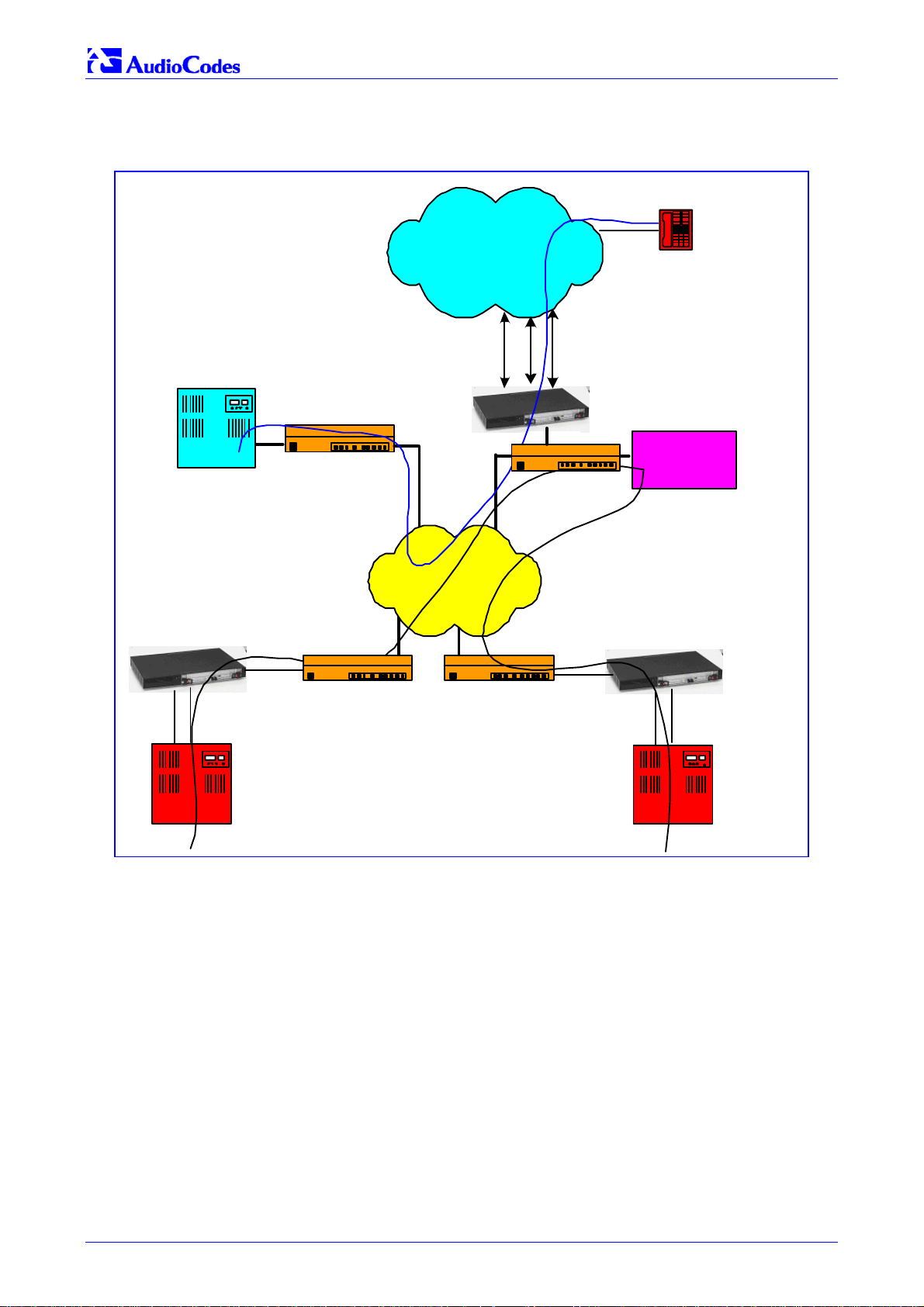
Figure 1-1 below illustrates typical Mediant 2000 gateway applications over VoIP Network.
SIP
Service
Node
Figure
1-1: Typical Mediant 2000 Gateway Application
Telephone
SIP Proxy
Router
LAN
PSTN
LAN
IP Network
E1/T1 PRI/CAS
Mediant 2000
Router
Mediant 2000
LAN
Router
E1/T1 PRI/CAS
PBX - Branch A
Router
1.1 Available Configurations
The Mediant 2000 is provided in the following configurations:
E1 Available Configurations:
• 30 Channels on 1 E1 span with gateway-1 only
• 60 Channels on 2 E1 spans with gateway-1 only
• 120 Channels on 4 E1 spans with gateway-1 only
Mediant 2000
LAN
E1/T1 PRI/CAS
PBX - Br an ch B
• 240 Channels on 8 E1 spans with gateway-1 only
• 480 Channels on 16 E1 spans with gateway-1 and gateway-2
T1 Available Configurations:
• 24 Channels on 1 T1 span with gateway-1 only
Mediant 2000 SIP User’s Manual 14 Document #: LTRT-72504
Page 15

Mediant 2000 SIP User’s Manual 1. Overview
• 48 Channels on 2 T1 spans with gateway-1 only
• 96 Channels on 4 T1 spans with gateway-1 only
• 192 Channels on 8 T1 spans with gateway-1 only
• 384 Channels on 16 T1 spans with gateway-1 and gateway-2
1.2 SIP Overview
SIP is an application-layer control (signaling) protocol used on the Mediant 2000 for creating,
modifying, and terminating sessions with one or more participants. These sessions can include
Internet telephone calls, media announcements and conferences.
SIP invitations are used to create sessions and carry session descriptions that enable participants
to agree on a set of compatible media types. SIP uses elements called proxy servers to help
route requests to the user's current location, authenticate and authorize users for services,
implement provider call-routing policies and provide features to users.
SIP also provides a registration function that enables users to upload their current locations for
use by proxy servers. SIP, on the Mediant 2000, complies with the IETF (Internet Engineering
Task Force) RFC 3261 (refer to http://www.ietf.org
).
1.3 Mediant 2000 Features
This section provides a high-level overview of some of the many Mediant 2000 supported
features.
1.3.1 General Features
• Superior, high quality SIP PSTN gateway for Voice and fax over IP calls.
• Up to 16 E1/T1/J1 digital spans supporting various PRI and CAS protocols.
• Compliant with SIP (RFC 3261).
• Coders include: G.711, G.723.1, G.726, G.729A and NetCoder at 6.4 to 8.8 kbps, negotiable
per channel.
• T.38 fax with superior performance (handling a round-trip delay of up to nine seconds).
• Echo Canceler with up to 128 msec tail length.
• Silence suppression with Comfort Noise Generation.
• Web management for easy configuration and installation.
• Simple Network Management Protocol (SNMP) and Syslog support.
• Simple Network Time Protocol (SNTP) support, the time-of-day can be obtained from a
standard SNTP server.
1.3.2 Hardware Features
• Two 10/100 Base-TX Ethernet interface connections to the network, providing network
redundancy.
• Compact, rugged 19-inch rack mount unit, one U high (1.75" or 44.5 mm), with two
compactPCI
• Optional cPCI slot for third-party CPU board.
• TP-1610/H.323 hot-swap cPCI board.
• Optional dual redundant AC or a single DC power supply.
Version 4.4 15 July 2005
™
(cPCI) slots.
Page 16

Mediant 2000 SIP
1.3.3 PSTN-to-SIP Interworking
The Mediant 2000 gateway performs interworking between ISDN and CAS via E1/T1/J1 digital
spans and SIP IETF signaling protocol. 16 E1, T1 or J1 spans are supported (480 channels) in a
two modules gateway.
The Mediant 2000 gateway supports various ISDN PRI protocols such as EuroISDN, North
American NI2, Lucent 4/5ESS, Nortel DMS100, Meridian 1 DMS100, Japan J1, as well as QSIG
(basic call). PRI support includes User Termination or Network Termination side. ISDN-PRI
protocols can be defined on an E1/T1 basis (i.e., different variants of PRI are allowed on different
E1/T1 spans).
In addition, it supports numerous variants of CAS protocols for E1 and T1 spans, including MFC
R2, E&M wink start, E&M immediate start, E&M delay dial/start, loop-start, and ground start. CAS
protocols can be defined on an E1/T1 basis (i.e., different variants of CAS are allowed on
different E1/T1 spans).
PSTN to SIP and SIP to PSTN Called number can be optionally modified according to rules that
are defined in gateway ini file.
1.3.3.1 Supported Interworking Features
• Definition and use of Trunk Groups for routing IPPSTN calls.
• B-channel negotiation for PRI spans.
• ISDN Non Facility Associated Signaling (NFAS).
• PRI to SIP interworking according to draft-ietf-sipping-qsig2sip-04.txt.
• PRI to SIP Interworking of Q.931 Display (Calling name) information element.
• PRI (NI-2) to SIP interworking of Calling Name using Facility IE in Setup and Facility
messages.
• Configuration of Numbering Plan and Type for IPISDN calls
• Interworking of PSTN to SIP release causes
• Interworking of ISDN redirect number to SIP diversion header (according to IETF draft-levy-
sip-diversion-05.txt).
• Optional change of redirect number to called number for ISDN IP calls.
• Interworking of ISDN calling line Presentation & Screening indicators using RPID header
<draft-ietf-sip-privacy-04.txt>.
• Interworking of Q.931 Called and Calling Number Type and Number Plan values using the
RPID header.
• Supports ISDN en-block or overlap dialing for incoming TelIP calls.
• Supports routing of IPTel calls to predefined trunk groups.
• Supports a configurable channel select mode per trunk group.
• Supports various number manipulation rules for IPTel and TelIP, called and calling
numbers.
• Option to configure ISDN Transfer Capability (per Gateway).
1.3.4 Supported SIP Features
The Mediant 2000 SIP main features are:
• Reliable User Datagram Protocol (UDP) transport, with retransmissions.
• T.38 real time fax (using SIP).
Note: If the remote side includes the fax maximum rate parameter in the SDP body of the
Invite message, the gateway returns the same rate in the response SDP.
Mediant 2000 SIP User’s Manual 16 Document #: LTRT-72504
Page 17

Mediant 2000 SIP User’s Manual 1. Overview
• Works with Proxy or without Proxy, using an internal routing table.
• Fallback to internal routing table if Proxy is not responding.
• Supports up to four Proxy servers. If the primary Proxy fails, the Mediant 2000 automatically
switches to a redundant Proxy.
• Supports Proxy server discovery using Domain Name Server (DNS) SRV records.
• Proxy and Registrar Authentication (handling 401 and 407 responses) using Basic or Digest
methods.
• Supported methods: INVITE, CANCEL, BYE, ACK, REGISTER, OPTIONS, INFO, REFER,
UPDATE, NOTIFY, PRACK and SUBSCRIBE.
• Modifying connection parameters for an already established call (re-INVITE).
• Working with a Redirect server and handling 3xx responses.
• Early Media (supporting 183 Session Progress).
• PRACK reliable provisional responses <RFC 3262>.
• Call Hold and Transfer Supplementary services using REFER, Refer-To, Referred-By,
Replaces and NOTIFY messages.
• Supports RFC 3327 – Adding “Path” to Supported header.
• Supports RFC 3581 – Symmetric Response Routing.
• Session Timer <draft-ietf-sip-session-timer-10.txt>.
• RFC 2833 Relay for Dual Tone Multi Frequency (DTMF) digits, including payload type
negotiation.
• DTMF out-of-band transfer using:
INFO method <draft-choudhuri-sip-info-digit-00.txt>
INFO method, compatible with Cisco gateways
NOTIFY method <draft-mahy-sipping-signaled-digits-01.txt>.DTMF out-of-band transfer
using INFO method (draft-choudhuri-sip-info-digit-00.txt)
• Can negotiate coder from a list of given coders.
• Supported coders:
G.711 A-law 64 kbps (10, 20, 30, 40, 50, 60, 80, 100, 120 msec)
G.711 µ-law 64 kbps (10, 20, 30, 40, 50, 60, 80, 100, 120 msec)
G.723.1 5.3, 6.3 kbps (30, 60, 90, 120 msec)
G.726 32 kbps (10, 20, 30, 40, 50, 60, 80, 100, 120 msec)
G.729A 8 kbps (10, 20, 30, 40, 50, 60, 80, 100 msec)
G.729B is supported if Silence Suppression is enabled.
NetCoder 6.4, 7.2, 8.0 and 8.8 kbps (20, 40, 60, 80, 100, 120 msec).
EVRC* 8, 4, 1 kbps (20, 40, 60, 80, 100, 120 msec)
AMR* 4.75, 5.15, 5.90, 6.70, 7.40, 7.95, 10.2, 12.2 kbps (20 msec)
Transparent (20, 40, 60, 80, 100, 120 msec)
* When EVRC (Enhanced Variable Rate Codec) and AMR (Adaptive Multi-Rate) are used, the
number of available gateway channels is reduced (refer to the documentation of the parameter
’CoderName’ in Table
For more updated information on the gateway’s supported features, refer to the latest Mediant
2000 & TP-1610 SIP Release Notes.
Version 4.4 17 July 2005
6-3).
Page 18

Mediant 2000 SIP
Reader’s Notes
Mediant 2000 SIP User’s Manual 18 Document #: LTRT-72504
Page 19
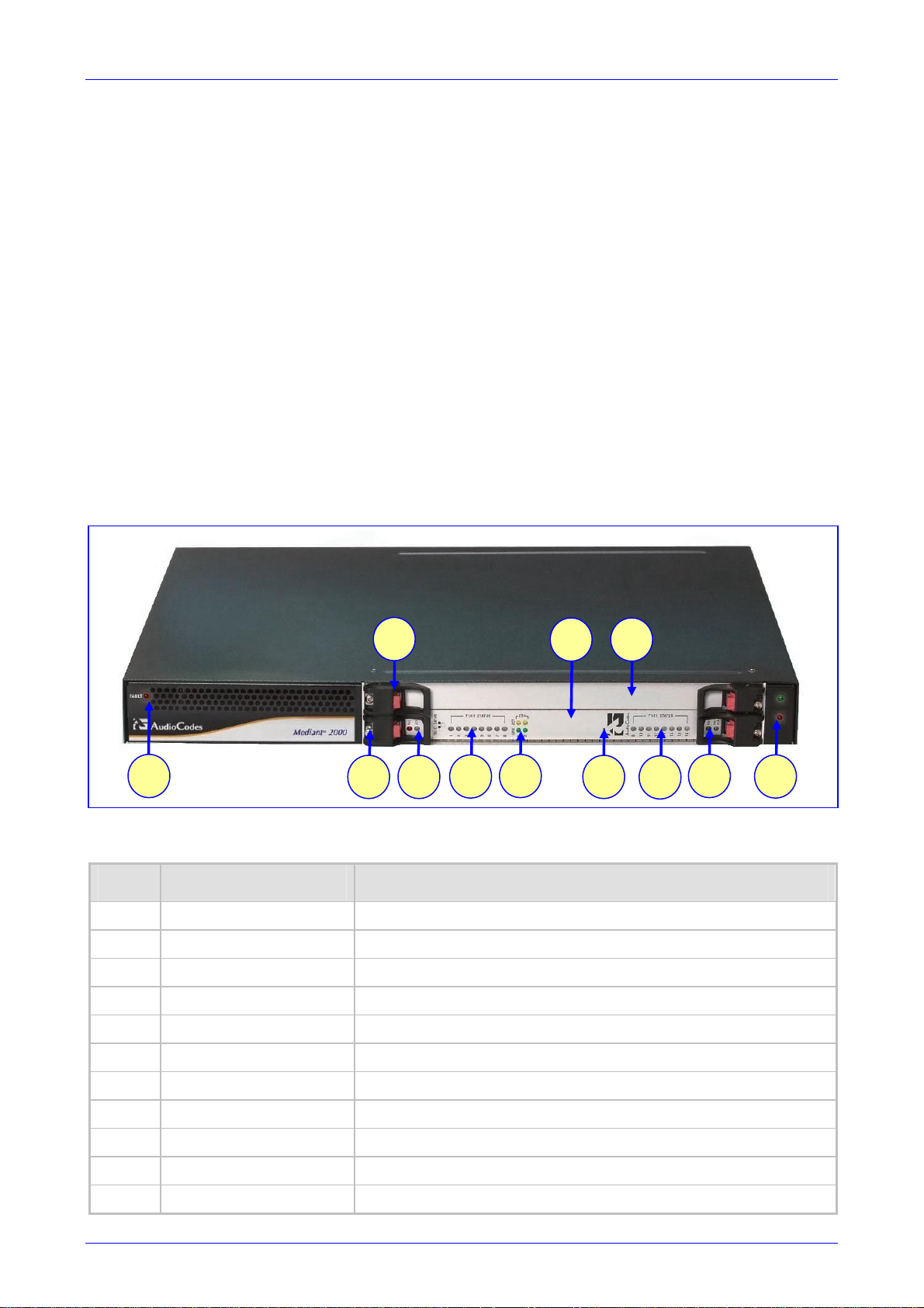
Mediant 2000 SIP User’s Manual 2. Mediant 2000 Physical Description
2 Mediant 2000 Physical Description
This section provides detailed information on the Mediant 2000 hardware components, the
location and functionality of the LEDs, buttons and connectors on the front and rear panels.
2.1 General
The Mediant 2000 gateway comprises the following hardware components:
• A 19-inch 1U high rack mount chassis (refer to Section
• A single compactPCI™ TP-1610 board (refer to Section
• A single TP-1610 Rear Transition Module (RTM) (refer to Section
• A single available cPCI slot for an optional third-party CPU board (refer to Section
page 25).
Figure
1 7
2-1 shows the front view of the Mediant 2000 media gateway.
Figure
2-1: Mediant 2000 Front View
3
2
5
6
2.2 on page 20).
2.3 on page 20).
2.4 on page 24).
4
11
8
6
9
2.5 on
10
2-1: Mediant 2000 Front View Component Descriptions
Table
Item # Label Component Description
1 FAULT Dual AC Power LED.
2 cPCI board locking screws.
3 cPCI latches.
4 TP-1610 cPCI board, 16-trunk configuration.
5 Status LED Indicators.
6 T1/E1 STATUS E1/T1 Trunk Status LED Indicators.
7 ETH Ethernet LED Indicators.
8 Reset button.
9 cPCI LED Indicators.
10 Power and Fan LEDs
11 An available cPCI slot for an optional third-party CPU board.
Version 4.4 19 July 2005
Page 20

Mediant 2000 SIP
2.2 The Mediant 2000 Chassis
The Mediant 2000 chassis is an industrial platform, 19” wide, 1U high and 12” deep that houses
the TP-1610 board in its front cage, slot #1 (the lower slot) and the TP-1610 RTM in its rear cage,
slot #1 (the lower slot).
Slot # 2 in the Mediant 2000 chassis’ front and rear cages can optionally be used by customers
for a CPU board.
Refer to Table
Location Color Function
Right side of front panel Green
Right side of front panel Red
Left side of front panel Red
2-2 for detailed description of the chassis’ LED indicators.
Table
2-2: Chassis LED Indicators
The power is on.
Fan failure - indicates that any of the internal fans has significantly
reduced its speed or has frozen.
Power supply failure - indicates that one of the two AC redundant
power supplies is faulty or disconnected from the AC/mains outlet.
(This LED is only relevant for the dual AC power supply).
2.2.1 Power Supply
The Mediant 2000 power supply is available in three configuration options:
• Single universal 100-240 VAC 1 A max, 50-60 Hz.
• Dual-redundant 100-240 VAC 1.5 A max, 50-60 Hz.
• -48 VDC power supply suitable for field wiring applications.
2.3 The TP-1610 Board
The Mediant 2000 is populated by a single compactPCI™ board, the TP-1610 (shown in Figure
2-2). The TP-1610 is a high-density, hot-swappable, cPCI resource board with a capacity of up to
480 ports, supporting all necessary functions for voice, data and fax streaming over IP networks.
The TP-1610 is composed of one or two identical media gateways modules: Gateway-1 and
Gateway-2, each containing 240 DSP channels. These media gateways are fully independent,
each gateway having its own MAC (Media Access Control) and IP addresses and LED indicators.
The TP-1610 board is supplied with a rear I/O configuration in which both PSTN trunks and
Ethernet interface are located on a passive rear I/O module (for information on the RTM, refer to
Section
2.4 on page 24).
Mediant 2000 SIP User’s Manual 20 Document #: LTRT-72504
Page 21
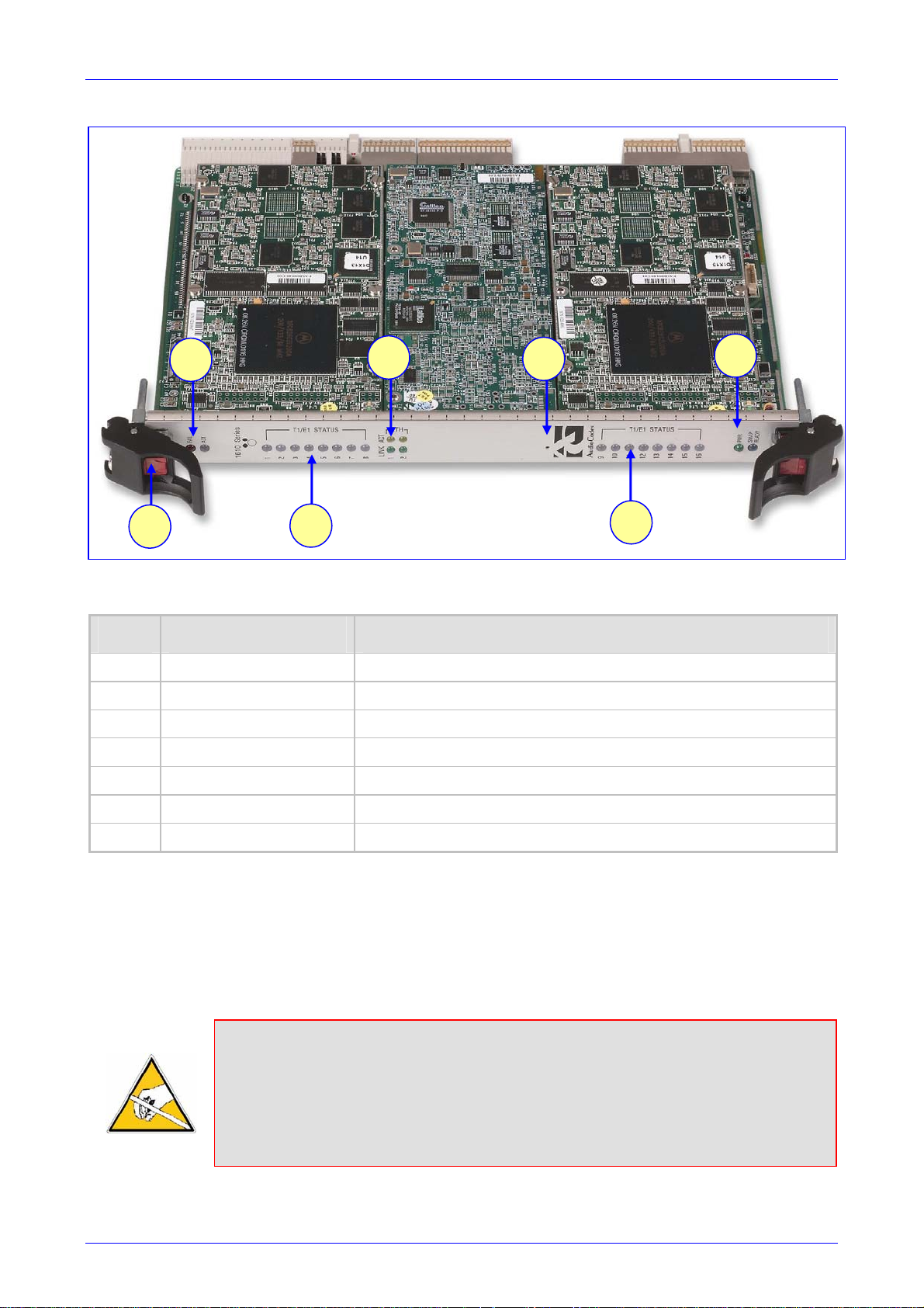
Mediant 2000 SIP User’s Manual 2. Mediant 2000 Physical Description
Figure 2-2: Front and Upper View of the TP-1610 cPCI Board
1
5
2-3: Front and Upper View of the TP-1610 cPCI Board Component Descriptions
Table
Item # Label Component Description
1 Status LEDs
2 ETH Ethernet LEDs
3 Reset button
4 cPCI LEDs
5 cPCI Latch
6
2
3
7
4
6 T1 / E1 STATUS T1/E1 Trunk Status LEDs (for each of trunks 1 to 8)
7 T1 / E1 STATUS T1/E1 Trunk Status LEDs (for each of trunks 9 to 16)
2.3.1 Board Hot-Swap Support
The TP-1610 cPCI board is hot-swappable and can therefore be removed from a slot (and
inserted into a slot) while the Mediant 2000 is under power. It is recommended though that you
power down the chassis and read the notes below before replacing the components.
For details on removing/inserting the optional CPU board, refer to the directions accompanying it.
Electrical Component Sensitivity
Electronic components on printed circuit boards are extremely sensitive to static
electricity. Normal amounts of static electricity generated by clothing can damage
electronic equipment. To reduce the risk of damage due to electrostatic discharge when
installing or servicing electronic equipment, it is recommended that anti-static earthing
straps and mats be used.
Version 4.4 21 July 2005
Page 22

Mediant 2000 SIP
Note 1: Before removing or inserting boards from / to the chassis, attach a wrist strap
for electrostatic discharge (ESD) and connect it to the rack frame using an
alligator clip.
Note 2: Do not set components down without protecting them with a static bag.
2.3.1.1 Removing Boards
To remove the TP-1610 board from the chassis, take these 3 steps:
1. Unfasten the screws on the plate of the board.
2. Press the red ejector buttons on the two black ejector/injector latches on both ends and wait
for the hot-swap blue LED to light, indicating that the board can be removed.
3. Pull on the two ejector/injector latches and ease out the board from the slot.
To remove the TP-1610 RTM from the chassis, take these 4 steps:
1. Remove the cables attached to the RTM.
2. Unfasten the screws on the brackets at both ends of the panel that secure the RTM to the
chassis.
3. Press the red ejector buttons on the two black ejector/injector latches on both ends.
4. Grasp the panel and ease the RTM board out of the slot.
2.3.1.2 Inserting Boards
To insert the TP-1610 board into the chassis, take these 6 steps:
1. Hold the board horizontally.
2. With the black ejector/injector latches in the open (pulled out) position, insert the board in the
slot, aligning the board with the grooves on each end.
3. Ease the board all the way into the slot until the ejector/injector latches touch the chassis.
The Blue hot-swap LED is lit.
4. Press the two black ejector/injector latches on both ends inward, toward the middle, until you
hear a click.
5. Wait for the hot-swap blue LED to turn off.
6. Fasten the screws on the front panel of the board to secure the board to the chassis and to
ensure that the board has a chassis earthing connection.
To insert the TP-1610 RTM into the chassis, take these 6 steps:
1. Hold the board horizontally.
2. With the black ejector/injector latches in the open (pulled out) position, insert the board in the
slot, aligning the board with the grooves on each end.
3. Ease the board all the way into the slot until the ejector/injector latches touch the chassis.
4. Press the two black ejector/injector latches on both ends inward, toward the middle until you
hear a click.
5. Fasten the screws on the front panel of the board to secure the board to the chassis and to
ensure that the board has a chassis earthing connection.
6. Reattach the cables (refer to Section
Mediant 2000 SIP User’s Manual 22 Document #: LTRT-72504
3.4 on page 30).
Page 23
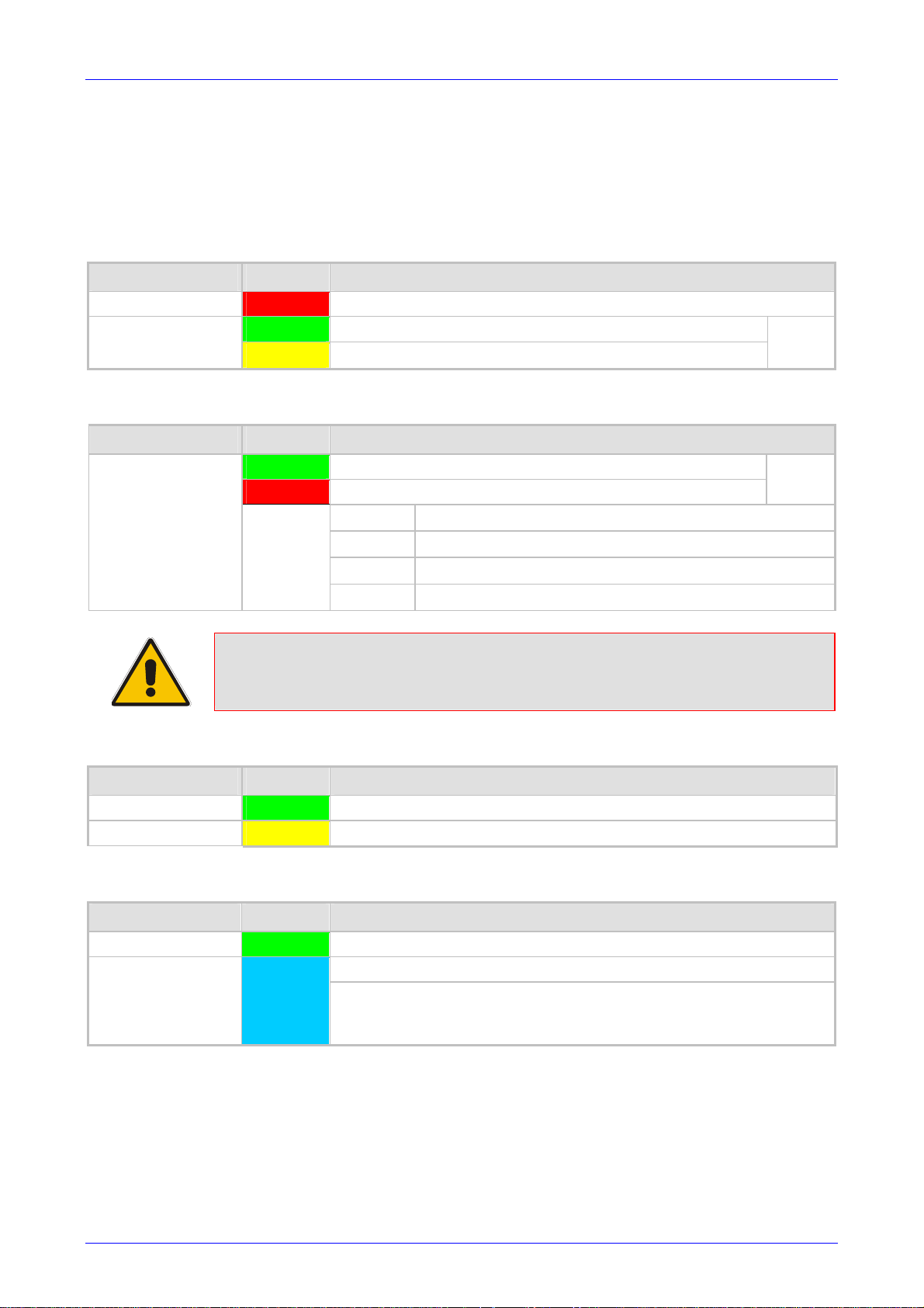
Mediant 2000 SIP User’s Manual 2. Mediant 2000 Physical Description
2.3.2 TP-1610 Front Panel LED Indicators
The functionality of the front panel LEDs for the TP-1610 is described in the following four tables
and illustrated in Figure
the number of channels.
Label LED Color LED Function
2-2 on page 21. Note that there is a choice of front panels according to
Table
2-4: Status LED Indicators
FAIL Red
ACT
Label LED Color Signal Description
T1/E1 Status 1 to 8
and
T1/E1 Status 9 to 16
Normally OFF; Red indicates gateway failure (fatal error)
Green
Yellow
Green
Red
Note: On the front panel 16 LEDs are provided for 16-span units and 8 LEDs are
provided for 1-span, 2-span, 4-span, and 8-span units. In the case of 1-span,
2-span and 4-span units, the extra LEDs are unused.
Gateway initialization sequence terminated OK
N/A
Table 2-5: E1/T1 Trunk Status LED Indicators
Trunk is synchronized (normal operation)
Loss due to any of the following 4 signals:
LOS
LFA
AIS
RAI
Table 2-6: Ethernet LED Indicators
Loss of Signal
Loss of Frame Alignment
Alarm Indication Signal (the Blue Alarm)
Remote Alarm Indication (the Yellow Alarm)
Bi-color
LED
Bi-color
LED
Label LED Color LED Function
LINK Green
ACT Yellow
Label LED Color LED Function
PWR Green
SWAP READY Blue
During correct Mediant 2000 operation, the ACT LED is lit green, the FAIL LED is off. Changing
of the FAIL LED to red indicates a failure.
Link all OK
Transmit / receive activity
Table 2-7: cPCI LED Indicators
Power is supplied to the board
The cPCI board can now be removed.
The cPCI board was inserted successfully.
For detailed information on the Swap-Ready LED, refer to Section
2.3.1 on page 21.
Version 4.4 23 July 2005
Page 24
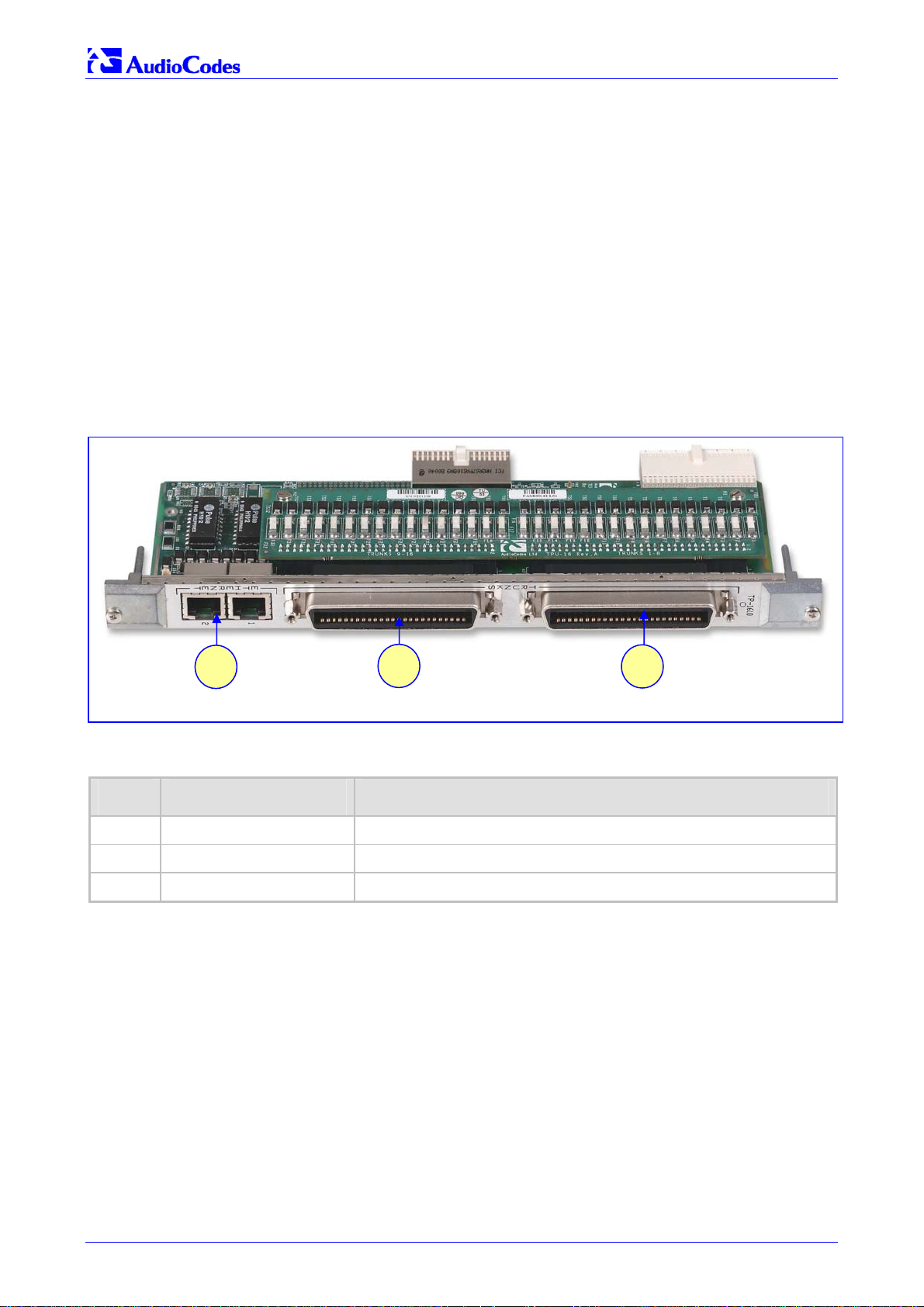
Mediant 2000 SIP
2.4 Rear Transition Module
The Mediant 2000 RTM includes a PSTN trunks and an Ethernet interfaces.
The Ethernet interface features dual 10/100 Base-TX, RJ-45 shielded connectors for (an active /
standby) redundancy scheme providing protection against the event of a failure.
The PSTN interface is provided with a choice of rear panels (1-span, 2-span, 4-span, 8-span or
16-span).
Rear panel with two 50-pin female Telco connectors (DDK 57AE-40500-21D) (shown in Figure
2-3) is required for a gateway equipped with up to 16 E1/T1 spans. Rear panel with RJ-48c
connectors (shown in Figure
spans. The physical difference between the 1-Span, 2-Span and 4-Span RTMs, and the 8-span
RTM is that the RJ-48c ports are depopulated correspondingly.
2-4) is required for a gateway equipped with 1, 2, 4, or 8 E1/T1
Figure
1
2-8: Rear Panel with two 50-pin Connectors for 16 Trunks Componen t Descriptions
Table
Item # Label Component Description
1 ETHERNET 2 Ethernet Ports. 2 RJ-45 network connectors.
2 TRUNKS E1/T1 trunks 9 to 16. 50-pin male Telco connector.
2-3: Rear Panel with two 50-pin Connectors for 16 Trunks
2
3
3 TRUNKS E1/T1 trunks 1 to 8. 50-pin male Telco connector.
Mediant 2000 SIP User’s Manual 24 Document #: LTRT-72504
Page 25

Mediant 2000 SIP User’s Manual 2. Mediant 2000 Physical Description
Figure 2-4: Rear Panel with 8 RJ-48c Connectors for 8 Trunks
1
2-9: Rear Panel with 8 RJ-48c Connectors for 8 Trunks Component Descriptions
Table
Item # Label Component Description
1 ETHERNET 2 Ethernet Ports. 2 RJ-45 network connectors
2 TRUNKS 8 E1/T-1 Spans. 8 RJ-48c trunk connectors
2
2.5 Optional CPU Board
The Mediant 2000 provides an optional second cPCI slot that can be optionally used for
customer’s CPU board. This CPU board can be used for general applications such as a
Gatekeeper, Softswitch, Application Server or other. The following CPU boards were tested for
compliancy with the Mediant 2000 chassis:
• Sun™: CP2080 + PMC-233 (Ramix™ disk on board) + Rear Transition Module (RTM).
• Intel™ ZT5515B-1A with 40GB on-board disk plus RTM (ZT4807).
Version 4.4 25 July 2005
Page 26

Mediant 2000 SIP
Reader’s Notes
Mediant 2000 SIP User’s Manual 26 Document #: LTRT-72504
Page 27

Mediant 2000 SIP User’s Manual 3. Installing the Mediant 2000
3 Installing the Mediant 2000
This section describes the hardware installation procedures for the Mediant 2000. For information
on how to start using the gateway, refer to Section
Mediant 2000 connectors, LEDs and buttons, refer to Section
Caution Electrical Shock
The equipment must only be installed or serviced by qualified service personnel.
To install the Mediant 2000, take these 4 steps:
1. Unpack the Mediant 2000 (refer to Section 3.1 below).
4 on page 35. For detailed information on the
2 on page 19.
2. Check the package contents (refer to Section
3. Mount the Mediant 2000 (refer to Section
4. Cable the Mediant 2000 (refer to Section
After powering-up the Mediant 2000, the Ready and LAN LEDs on the front panel turn to green
(after a self-testing period of about 3 minutes). Any malfunction changes the Ready LED to red
(refer to Section
When you have completed the above relevant sections you are then ready to start configuring the
gateway (Section
2.3.2 on page 23 for details on the Mediant 2000 LEDs).
4 on page 35).
3.1 Unpacking
To unpack the Mediant 2000, take these 6 steps:
1. Open the carton and remove packing materials.
2. Remove the Mediant 2000 gateway from the carton.
3. Check that there is no equipment damage.
4. Check, retain and process any documents.
5. Notify AudioCodes or your local supplier of any damage or discrepancies.
6. Retain any diskettes or CDs.
3.2 below).
3.3 on page 28).
3.4 on page 30).
3.2 Package Contents
Ensure that in addition to the Mediant 2000, the package contains:
• For the dual AC power supply version two AC power cables are supplied; for the single AC
power supply version one AC power cable is supplied.
• For the DC power supply version, one connectorized DC power cable (crimp connection
type) and one DC adaptor (screw connection type) connected to the rear panel of the
Mediant 2000 are supplied; use only one type.
• CD (software and documentation).
• Small plastic bag containing (refer to Figure
Two brackets and four bracket-to-device screws for 19-inch rack installation option.
Four anti-slide bumpers for desktop / shelf installation option.
• The Mediant 2000 Fast Track Installation Guide.
Version 4.4 27 July 2005
3-1):
Page 28

Mediant 2000 SIP
Figure 3-1: 19-inch Rack & Desktop Accessories
3.3 Mounting the Mediant 2000
The Mediant 2000 can be mounted on a desktop, or installed in a standard 19-inch rack. Refer to
Section
3.4 on page 30 for cabling the Mediant 2000.
3.3.1 Mounting the Mediant 2000 on a Desktop
No brackets are required. Optionally, attach the four (supplied) anti-slide bumpers to the base of
the Mediant 2000 and place it on the desktop in the position you require.
3.3.2 Installing the Mediant 2000 in a 19-inch Rack
Users can install the device in a standard 19-inch rack either by placing the device on a shelf
preinstalled in the rack (preferred method), or by attaching the device directly to the rack’s frame
via integral brackets.
Before rack mounting the chassis, attach the two (supplied) brackets to the front sides of the
device (refer to Figure
To attach the two front side brackets, take these 3 steps:
1. Remove the 2 screws nearest the front panel on either side of the device.
2. Align a bracket over 2 holes on one side (so that the bracket’s larger holes face front) and
with the 2 supplied replacement screws, screw in the bracket.
3. Perform the same procedure on the other side.
3-2).
Mediant 2000 SIP User’s Manual 28 Document #: LTRT-72504
Page 29
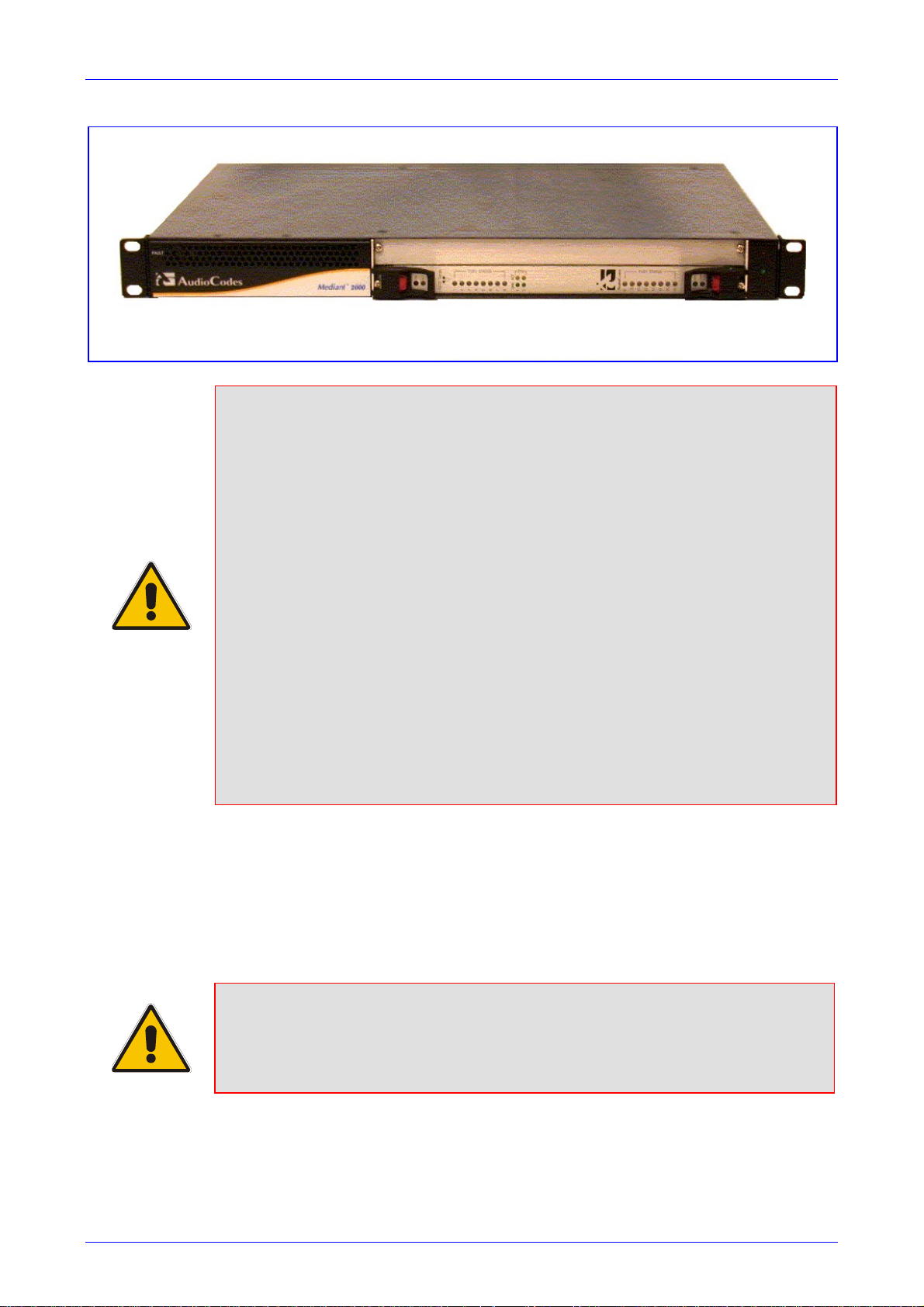
Mediant 2000 SIP User’s Manual 3. Installing the Mediant 2000
Figure 3-2: Mediant 2000 Front View with 19-inch Rack Mount Brack ets
Rack Mount Safety Instructions (UL)
When installing the chassis in a rack, be sure to implement the following Safety
instructions recommended by Underwriters Laboratories:
• Elevated Operating Ambient - If installed in a closed or multi-unit rack
assembly, the operating ambient temperature of the rack environment may be
greater than room ambient. Therefore, consideration should be given to
installing the equipment in an environment compatible with the maximum
ambient temperature (Tma) specified by the manufacturer.
• Reduced Air Flow - Installation of the equipment in a rack should be such that
the amount of air flow required for safe operation on the equipment is not
compromised.
• Mechanical Loading - Mounting of the equipment in the rack should be such
that a hazardous condition is not achieved due to uneven mechanical loading.
• Circuit Overloading - Consideration should be given to the connection of the
equipment to the supply circuit and the effect that overloading of the circuits
might have on overcurrent protection and supply wiring. Appropriate
consideration of equipment nameplate ratings should be used when addressing
this concern.
• Reliable Earthing - Reliable earthing of rack-mounted equipment should be
maintained. Particular attention should be given to supply connections other
than direct connections to the branch circuit (e.g., use of power strips.)
To attach the device to a 19-inch rack, take these 2 steps:
1. Position the device in your 19-inch rack and align the left-hand and right-hand bracket holes
to holes (of your choosing) in the vertical tracks of the 19-inch rack.
2. Use standard 19-inch rack bolts (not provided) to fasten the device to the frame of the rack.
AudioCodes recommends using two additional (not supplied) rear mounting brackets to provide
added support.
Note: Users assembling the rear brackets by themselves should note the following:
• The distance between the screws on each bracket is 26.5 mm.
• To attach the brackets, use 4-40 screws with a maximal box penetration length
of 3.5 mm.
To place the device on a 19-inch rack’s shelf, take these 2 steps:
1. Place the device on the preinstalled shelf.
Version 4.4 29 July 2005
Page 30
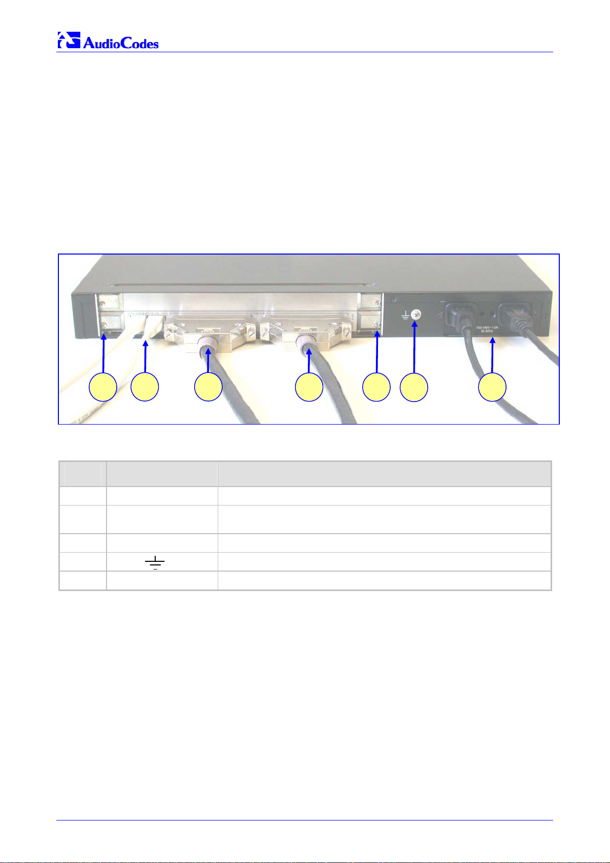
Mediant 2000 SIP
2. You’re now recommended to take the optional steps of fastening the device to the frame of
the rack (as described above) while it is placed on the shelf, so preventing it from sliding
when inserting cables into connectors on the rear panel.
3.4 Cabling the Mediant 2000
Refer to Section 2 on page 19 for detailed information on the Mediant 2000 rear panel connectors
and LEDs.
Note that the Mediant 2000 is available in many configurations, i.e., AC or DC, in the 16-trunk, 8trunk, 4-trunk, 2-trunk or 1-trunk device. The 16-trunk dual AC (Figure
(Figure
3-4) configurations are illustrated here as representative products.
3-3) and the 8-trunk DC
Figure
3-1: Mediant 2000 Rear Panel Cabling (16 Trunks, Dual AC Power) Component Descriptions
Table
Item # Label Component Description
1 RTM locking screws.
2
3-3: Mediant 2000 Rear Panel Cabling (16 Trunks, Dual AC Power)
2
ETHERNET
3
Two Category 5 network cables, connected to the 2 Ethernet RJ-45
ports.
21 1
4
5
3 TRUNKS Two 50-pin Telco connector cables, each supporting 8 trunks.
4
5 100-240~1.5A Dual AC power cables.
Mediant 2000 SIP User’s Manual 30 Document #: LTRT-72504
Protective earthing screw.
Page 31

Mediant 2000 SIP User’s Manual 3. Installing the Mediant 2000
Figure 3-4: Mediant 2000 Rear Panel Cabling (8 Trunks, DC Power))
1 13
3-2: Mediant 2000 Rear Panel Cabling (8 Trunks, DC Power) Component Descriptions
Table
Item # Label Component Description
1 RTM latches.
2 ETH A Category 5 network cable, connected to the Ethernet 1 RJ-45 port.
3 PSTN 8 RJ-48c ports, each supporting a trunk.
4
5 48V 4A max 2-pin connector for DC.
2
3
Protective earthing screw.
4
5
Electrical Earthing
The unit must be permanently connected to earth via the screw provided at the back on
the unit. Use 14-16 AWG wire and a proper ring terminal for the earthing.
To cable the Mediant 2000, take these 4 steps:
1. Permanently connect the device to a suitable earth with the protective earthing screw on the
rear connector panel, using 14-16 AWG wire.
2. Connect the E1/T1 trunk interfaces (refer to Section
3. Install the Ethernet connection (refer to Section
4. Connect the power supply (refer to Section
3.4.3 on page 33).
3.4.1 below).
3.4.2 on page 32).
3.4.1 Connecting the E1/T1 Trunk Interfaces
Connect the Mediant 2000 E1/T1 Trunk Interfaces using either Telco or RJ-48 connectors:
With 50-pin Telco connectors (16-trunk device), take these 3 steps:
1. Attach the Trunk cable with a 50-pin male Telco connector to the 50-pin female Telco
connector labeled “Trunks 18” on the Rear Transition Module (RTM).
2. Connect the other end of the Trunk cable to the PBX/PSTN switch.
Version 4.4 31 July 2005
Page 32

Mediant 2000 SIP
3. Repeat steps 1 and 2 for the other Trunk cable but this time connect it to the connector
labeled “Trunks 916”.
The 50-pin male Telco cable connector must be wired according to the pinout in Table
and to mate with the female connector illustrated in Figure
Figure
3-5: 50-pin Female Telco Board-Mounted Connector
Pin Numbers
50
3-5.
125
26
3-3 below,
Table 3-3: E1/T1 Connections on each 50-pin Telco Connector
E1/T1 Number
Tx Pins (Tip/Ring) Rx Pins (Tip/Ring)
1 to 8 9 to 16
1 9 27/2 26/1
2 10 29/4 28/3
3 11 31/6 30/5
4 12 33/8 32/7
5 13 35/10 34/9
6 14 37/12 36/11
7 15 39/14 38/13
8 16 41/16 40/15
With RJ-48c Connectors, take these 2 steps:
1. Connect the E1/T1 trunk cables to the ports labeled “Trunks 1 to 8” (in the case of the 8-
trunk device) on the Mediant 2000 RTM.
2. Connect the other ends of the Trunk cables to the PBX/PSTN switch.
RJ-48c trunk connectors are wired according to Figure
Figure
3-6: Pinout of RJ-48c Trunk Connectors
RJ-48c Connector and Pinout
1 2 3 4 5 6 7 8
1 = Rx Ring
2 = Rx Tip
4 = Tx Ring
5 = Tx Tip
3.4.2 Installing the Ethernet Connection
Connect a standard Category 5 network cable to the Ethernet RJ-45 port (and the other as
optional redundancy/backup). Connect the other end of the Category 5 network cables to your IP
network. The Ethernet connectors (labeled Ethernet 1 and Ethernet 2) are wired according to
Figure
3-7.
3-6 below.
3, 6, 7, 8
not connected
body = shield
Note that for redundant operation it is recommended to connect each of the Ethernet connectors
to a different Switch.
When assigning an IP address to the Mediant 2000 using HTTP (under Step
1 in Section 4.1.1),
you may be required to disconnect this cable and re-cable it differently.
Mediant 2000 SIP User’s Manual 32 Document #: LTRT-72504
Page 33

Mediant 2000 SIP User’s Manual 3. Installing the Mediant 2000
Figure 3-7: Pinout of RJ-45 Connectors
RJ-45 LAN Connector and Pinout
1 2 3 4 5 6 7 8
1 = Tx+
2 = Tx3 = Rx+
6 = Rx-
4, 5, 7, 8
not connected
3.4.3 Connecting the Power Supply
Connect the Mediant 2000 to the power supply using one of the following methods:
3.4.3.1 Connecting the AC Power Supply
When using a single AC power cable:
Attach one end of the supplied 100/240 VAC power cable to the rear AC socket and connect the
other end to the correct earthed AC power supply.
When using a dual AC power cable:
Attach one end of the supplied 100/240 VAC power cables to the rear AC sockets and connect
the other end to a separate earthed mains circuits (for power source redundancy).
Note: For the dual AC power supply note the following:
• The LED on the left side of the chassis is only connected when the dual AC is
used. It is not relevant to the single AC power connection.
• If only a single socket is connected to the AC power, (while the other plug is left
unconnected) the chassis’ LED (on the left side) is lit Red, indicating that one
of the dual power inlets is disconnected.
• When both the AC power cables are connected, one of the plugs can be
disconnected under power without affecting operation, in which case the
chassis’ left LED is lit Red.
• UPS can be connected to either (or both) of the AC connections.
• The dual AC connections operate in a 1 + 1 configuration and provide load-
sharing redundancy.
• Each of the dual power cables can be connected to different AC power phases.
3.4.3.2 Connecting the DC Power Supply
To connect the Mediant 2000 to a DC power supply use one of these two options:
• DC Terminal block with a screw connection type.
• DC Terminal block with a crimp connection type.
When using a DC terminal block screw connector, take these 3 steps:
1. Create a DC cable by inserting two 14-16 AWG insulated wires into the supplied adaptor
(refer to Figure
2. Connect the two insulated wires to the correct DC power supply. Ensure that the connections
to the DC power supply maintain the correct polarity.
3. Insert the terminal block into the DC inlet located on the Mediant 2000.
Version 4.4 33 July 2005
3-8) and fasten the two screws, each one located directly above each wire.
Page 34

Mediant 2000 SIP
Figure 3-8: DC Terminal Block Screw Connector
When using a DC terminal block crimp connector, take these 3 steps:
1. Remove the DC adaptor (screw connection type) that is attached to the Mediant 2000 rear
panel.
2. Connect the two insulated wires to the correct DC power supply. Ensure that the connections
to the DC power supply maintain the correct polarity (refer to Figure
3-9).
3. Insert the terminal block into the DC inlet located on the Mediant 2000.
Figure
2 screws for
connecting the
crimp terminal
block to the
Mediant 2000 rear
panel
3-9: DC Terminal Block Crimp Connector
Mediant 2000 SIP User’s Manual 34 Document #: LTRT-72504
Page 35

Mediant 2000 SIP User’s Manual 4. Getting Started
4 Getting Started
The Mediant 2000 is supplied with application software already resident in its flash memory (with
factory default parameters).
Section
on page 35 describes how to set up the Mediant 2000 with basic parameters using a standard
Web browser (such as Microsoft
For detailed information on how to fully configure the gateway, refer to the Web Interface,
described in Section
4.1 below describes how to assign IP addresses to the Mediant 2000, while Section 4.1.2
TM
Internet Explorer).
5 on page 39.
4.1 Assigning the Mediant 2000 IP Address
The Mediant 2000 is composed of one or two identical media gateway modules. These media
gateways are fully independent, each gateway having its own MAC and IP addresses (Table
shows the default IP addresses of the Mediant 2000). To assign an IP address to each of the
Mediant 2000 modules use one of the following methods:
• HTTP using a Web browser (refer to Section
• BootP (refer to Section
• Dynamic Host Control Protocol (DHCP) (refer to Section
You can use the ‘Reset’ button to restore the Mediant 2000 networking parameters to their factory
default values (refer to Section
Table
4-1: Mediant 2000 Default Networking Parameters
4.1.2 on page 36).
4.2 on page 36).
4.1.1 below).
10.2 on page 169).
4-1
Mediant 2000 Version Default Value
Single module (up to 8 Trunks) 10.1.10.10
Double module (up to 16 Trunks) 10.1.10.10 (Trunks 1-8) and 10.1.10.11 (Trunks 9-16)
Default subnet mask is 255.255.0.0, default gateway IP address is 0.0.0.0
4.1.1 Assigning an IP Address Using HTTP
To assign an IP address using HTTP, take these 9 steps:
1. Disconnect the Mediant 2000 from the network and reconnect it to your PC using one of the
following two methods:
Use a standard Ethernet cable to connect the network interface on your PC to a port on
a network hub / switch. Use a second standard Ethernet cable to connect the Mediant
2000 to another port on the same network hub / switch.
Use an Ethernet cross-over cable to directly connect the network interface on your PC
to the Mediant 2000.
2. Change your PC’s IP address and subnet mask to correspond with the Mediant 2000 factory
default IP address and subnet mask, shown in Table
address and subnet mask of your PC, refer to Windows™ Online Help (Start>Help).
3. Access the Mediant 2000 first module’s Embedded Web Server (refer to Section
41).
4-1. For details on changing the IP
5.6 on page
4. In the ‘Quick Setup’ screen (shown in Figure
‘Subnet Mask’ and ‘Default Gateway IP Address’ fields under ‘IP Configuration’ to
Version 4.4 35 July 2005
4-1), set the Mediant 2000 ‘IP Address’,
Page 36

Mediant 2000 SIP
correspond with your network IP settings. If your network doesn’t feature a default gateway,
enter a dummy value in the ‘Default Gateway IP Address’ field.
5. Click the Reset button and click OK in the prompt; The Mediant 2000 applies the changes
and restarts. This takes approximately 3 minutes to complete. When the Mediant 2000 has
finished restarting, the Ready and LAN LEDs on the front panel are lit green.
Tip: Record and retain the IP address and subnet mask you assign the Mediant
2000. Do the same when defining new username or password. If the
Embedded Web Server is unavailable (for example, if you’ve lost your
username and password), use the BootP/TFTP (Trivial File Transfer Protocol)
configuration utility to access the device, “reflash” the load and reset the
6. Repeat steps 3 to 5 for the Mediant 2000 second module (if used).
7. Disconnect your PC from the Mediant 2000 or from the hub / switch (depending on the
connection method you used in step Error! Reference source not found.).
8. Reconnect the Mediant 2000 and your PC (if necessary) to the network.
9. Restore your PC’s IP address and subnet mask to what they originally were. If necessary,
restart your PC and re-access the Mediant 2000 via the Embedded Web Server with its new
assigned IP address.
password (refer to Appendix B on page 189 for detailed information on using
a BootP/TFTP configuration utility to access the device).
4.1.2 Assigning an IP Address Using BootP
Note: BootP procedure can also be performed using any standard compatible
BootP server.
Tip: You can also use BootP to load the auxiliary files to the Mediant 2000 (refer
to Section 6.12.1 on page 132).
To assign an IP address using BootP, take these 4 steps:
1. Open the BootP application (supplied with the Mediant 2000 software package).
2. Add client configuration for the gateway that you want to initialize, refer to Section
page 195.
3. Reset the gateway physically causing it to use BootP; the Mediant 2000 changes its network
parameters to the values provided by the BootP.
4. Repeat steps 2 and 3 for the Mediant 2000 second module (if used).
B.11.1 on
4.2 Restoring Networking Parameters to their Initial State
You can use the ‘Reset’ button to restore the Mediant 2000 networking parameters to their factory
default values (described in Table
Note that the Mediant 2000 returns to the software version burned in flash. This process also
restores the Mediant 2000 parameters to their factory settings, therefore you must load your
previously backed-up ini file, or the default ini file (received with the software kit) to set them to
their correct values.
Mediant 2000 SIP User’s Manual 36 Document #: LTRT-72504
4-1) and to reset the username and password.
Page 37

Mediant 2000 SIP User’s Manual 4. Getting Started
This option is currently supported on one media gateway module (trunks 1-8) only.
To restore networking parameters to their initial state, take these 6
steps:
1. Disconnect the Mediant 2000 from the power and network cables.
2. Reconnect the power cable; the gateway is powered up. After approximately 45 seconds the
ACT LED blinks for about 4 seconds.
3. While the ACT LED is blinking, press shortly on the reset button (located on the front panel);
the gateway resets a second time and is restored with factory default parameters (username:
“Admin”, password: “Admin”).
4. Reconnect the network cable.
5. Assign the Mediant 2000 IP address (refer to Section
6. Load your previously backed-up ini file, or the default ini file (received with the software kit).
To load the ini file via the Embedded Web Server, refer to Section
4.1 on page 35).
5.9.5 on page 69.
4.3 Configuring the Mediant 2000 Basic Parameters
To configure the Mediant 2000 basic parameters use the Embedded Web Server’s ‘Quick Setup’
screen (shown in Figure
the ‘Quick Setup’ screen.
4-1 below). Refer to Section 5.6 on page 41 for information on accessing
Figure
4-1: Mediant 2000 Quick Setup Screen
To configure basic SIP parameters, take these 10 steps:
1. If the Mediant 2000 is connected to a router with NAT (Network Address Translation)
enabled, perform the following procedure. If it isn’t, leave the ‘NAT IP Address’ field
undefined.
Determine the “public” IP address assigned to the router (by using, for instance, router
Web management). Enter this public IP address in the ‘NAT IP Address’ field.
Version 4.4 37 July 2005
Page 38

Mediant 2000 SIP
Enable the DMZ (Demilitarized Zone) configuration on the residential router for the LAN
port where the Mediant 2000 gateway is connected. This enables unknown packets to
be routed to the DMZ port.
2. Under ‘SIP Parameters’, enter the Mediant 2000 domain name in the field ‘Gateway Name’.
If the field is not specified, the Mediant 2000 IP address is used instead (default).
3. When working with a Proxy server, set ‘Working with Proxy’ field to ‘Yes’ and enter the IP
address of the primary Proxy server in the field ‘Proxy IP address’. When no Proxy is used,
the internal routing table is used to route the calls.
4. Enter the Proxy name in the field ‘Proxy Name’. If Proxy name is used, it replaces the Proxy
IP address in all SIP messages. This means that messages is still sent to the physical Proxy
IP address but the SIP URI contains the Proxy name instead.
5. Configure ‘Enable Registration’ to ‘Yes’ or ‘No’:
‘No’ = the Mediant 2000 does not register to a Proxy server/Registrar (default).
‘Yes’ = the Mediant 2000 registers to a Proxy server/Registrar at power up and every
‘Registration Time’ seconds. For detailed information on the parameter ‘Registration Time’,
refer to Table
6. Select the coder (i.e., vocoder) that best suits your VoIP system requirements. The default
coder is: G.7231 30 msec. To program the entire list of coders you want the Mediant 2000 to
use, click the button on the left side of the ‘1st Coder’ field; the drop-down lists for the 2nd to
5th coders appear. Select coders according to your system requirements. Note that coders
higher on the list are preferred and take precedence over coders lower on the list.
6-3 on page 100.
Note: The preferred coder is the coder that the Mediant 2000 uses as a first choice
for all connections. If the far end gateway does not use this coder, the
Mediant 2000 negotiates with the far end gateway to select a coder that both
sides can use.
7. To program the Tel to IP Routing Table, press the arrow button next to ‘Tel to IP Routing
Table’. For information on how to configure the Tel to IP Routing Table, refer to Section
5.8.4.1 on page 49.
8. To program the E1/T1 B-channels, press the arrow button next to ‘Trunk Group Table’. For
information on how to configure the Trunk Group Table, refer to Section
9. Click the Reset button and click OK in the prompt; The Mediant 2000 applies the changes
and restarts, taking approximately 3 minutes to complete. When the Mediant 2000 has
finished restarting, the Ready and LAN LEDs on the front panel are lit green.
10. After the gateway was reset, access the Advanced Configuration>Trunk Settings page, and
select the gateway’s E1/T1 protocol type and Framing method that best suits your system
requirements. Note that for E1 spans, the framing method must always be set to ‘Extended
Super Frame’. For information on how to configure the Trunk Settings, refer to Section
on page 66.
You are now ready to start using the gateway. To prevent unauthorized access to the Mediant
2000, it is recommended that you change the username and password that are used to access
the Web Interface. Refer to Section
and password.
5.9.7 on page 71 for details on how to change the username
5.8.6 on page 58.
5.9.3
Tip: Once the gateway is configured correctly back up your settings by making a
copy of the VoIP gateway configuration (ini file) and store it in a directory on
your PC. This saved file can be used to restore configuration settings at a
future time. For information on backing up and restoring the gateway’s
configuration, refer to Section 5.9.5 on page 69.
Mediant 2000 SIP User’s Manual 38 Document #: LTRT-72504
Page 39

Mediant 2000 SIP User’s Manual 5. Web Management
5 Web Management
5.1 Configuration Concepts
Users can utilize the Mediant 2000 in a wide variety of applications, enabled by its parameters
and configuration files (e.g., Call Progress Tones (CPT), etc.). The parameters can be configured
and configuration files can be loaded using:
• A standard Web Browser (described and explained in this section).
• A configuration file referred to as the ini file. For information on how to use the ini file, refer to
Section
6 on page 87.
• An SNMP browser software (refer to Section
• AudioCodes’ Element Management System (EMS) (refer to Section
AudioCodes’ EMS User’s Manual or EMS Product Description).
To upgrade the Mediant 2000 (load new software or configuration files onto the gateway) use the
Software Upgrade wizard, available through the Web Interface (refer to Section
78), or alternatively use the BootP/TFTP configuration utility (refer to Section
169).
For information on the configuration files, refer to Section
11 on page 171).
11.8 on page 182 and to
7 on page 135.
5.2 Overview of the Embedded Web Server
The Embedded Web Server is used both for gateway configuration, including loading of
configuration files, and for run-time monitoring. The Embedded Web Server can be accessed
from a standard Web browser, such as Microsoft™ Internet Explorer, Netscape™ Navigator, etc.
Specifically, Users can employ this facility to set up the gateway configuration parameters. Users
also have the option to remotely reset the gateway and to permanently apply the new set of
parameters.
5.3 Computer Requirements
To use the Web Interface, the following is needed:
5.11.1 on page
10.3.1 on page
• A computer capable of running your Web browser.
• A network connection to the VoIP gateway.
• One of the following compatible Web browsers:
Microsoft™ Internet Explorer™ (version 6.0 and higher).
Netscape™ Navigator™ (version 7.0 and higher).
Note: Some Java-script applications are not supported in Netscape.
Version 4.4 39 July 2005
Page 40

Mediant 2000 SIP
5.4 Password Control
The Embedded Web Server is protected by a unique username and password combination. The
first time a browser request is made, the User is requested to provide his username and
password to obtain access. Subsequent requests are negotiated by the browser on behalf of the
User, so that the User doesn’t have to re-enter the username and password for each request, but
the request is still authenticated (the Embedded Web Server uses the MD5 authentication
method supported by the HTTP 1.1 protocol).
An additional level of protection is obtained by a restriction that no more than three IP addresses
can access the Embedded Web Server concurrently. With this approach, a fourth User is told that
the server is busy, even if the correct username and password were provided.
5.4.1 Embedded Web Server Username & Password
The default username and password for all gateways are:
• Username = “Admin” (case-sensitive)
• Password = “Admin” (case-sensitive)
For details on changing the username and password, refer to Section
the password and username can be a maximum of 7 case-sensitive characters.
5.9.7 on page 71. Note that
The User can reset the Web username and password (to the default values) by enabling an ini
file parameter called ‘ResetWebPassword’. The Web password is automatically the default
password.
5.5 Configuring the Web Interface via the ini File
Two additional security preferences can be configured using ini file parameters. These security
levels provide protection against unauthorized access (such as Internet hacker attacks),
particularly to Users without a firewall. For information on the ini file, refer to Section
87.
5.5.1 Limiting the Embedded Web Server to Read-Only Mode
Users can limit the Web Interface to read-only mode by changing the ini file parameter
‘DisableWebConfig’ to 1. In this mode all Web screens are read-only and cannot be modified. In
addition, the following screens cannot be accessed: ‘Quick Setup’, ‘Change Password’, ’Reset‘,
‘Save Configuration‘, ‘Software Upgrade Wizard’, ‘Load Auxiliary Files’, ‘Configuration File’ and
‘Regional Settings’.
5.5.2 Disabling the Embedded Web Server
To deny access to the gateway through HTTP protocol, the User can disable the Embedded Web
Server task. To disable the Web task, use the ini file parameter ‘DisableWebTask = 1’. The
default is to Web task enabled.
6 on page
Mediant 2000 SIP User’s Manual 40 Document #: LTRT-72504
Page 41

Mediant 2000 SIP User’s Manual 5. Web Management
5.6 Accessing the Embedded Web Server
To access the Embedded Web Server, take these 4 steps:
1. Open a standard Web-browsing application such as Microsoft™ Internet Explorer™ (Version
6.0 and higher) or Netscape™ Navigator™ (Version 7.0 and higher).
2. In the Uniform Resource Locator (URL) field, specify the IP address of the Mediant 2000
(e.g., http://10.1.10.10); the Embedded Web Server’s ‘Enter Network Password’ screen
appears, shown in Figure
5-1.
Figure
3. In the ‘User Name’ and ‘Password’ fields, enter the username (default: “Admin”) and
password (default: “Admin”). Note that the username and password are case-sensitive.
4. Click the OK button; the ‘Quick Setup’ screen is accessed (shown in Figure
5-1: Embedded Web Server Login Screen
4-1).
5.6.1 Using Internet Explorer to Access the Embedded Web Server
Internet explorer’s security settings may block access to the gateway’s Web browser if they’re
configured incorrectly. In this case, the following message is displayed:
Unauthorized
Correct authorization is required for this area. Either your browser does not perform
authorization or your authorization has failed. RomPager server.
To troubleshoot blocked access to Internet Explorer, take these 2
steps:
1. Delete all cookies from the Temporary Internet files. If this does not clear up the problem, the
security settings may need to be altered (refer to Step 2).
2. In Internet Explorer, Tools, Internet Options select the Security tab, and then select Custom
Level. Scroll down until the Logon options are displayed and change the setting to Prompt
for username and password and then restart the browser. This fixes any issues related to
domain use logon policy.
Version 4.4 41 July 2005
Page 42

Mediant 2000 SIP
r
g
r
5.7 Getting Acquainted with the Web Interface
Figure 5-2 shows the general layout of the Web Interface screen.
Main Menu
Ba
Submenu
Ba
Corporate
Lo
Control
Protocol
Figure
o
5-2: Mediant 2000 Web Interface
MG Module
Title Bar
Main Action
Frame
The Web Interface screen features the following components:
• Title bar - contains three configurable elements: corporate logo, a background image and
the product’s name. For information on how to modify these elements, refer to
on page 207.
• Main menu bar - always appears on the left of every screen to quickly access parameters,
submenus, submenu options, functions and operations.
• Submenu bar - appears on the top of screens and contains submenu options.
• Main action frame - the main area of the screen in which information is viewed and
configured.
• Corporate logo – AudioCodes’ corporate logo. For information on how to remove this logo,
refer to
• Control Protocol – the Mediant 2000 control protocol.
• MG Module – the Mediant 2000 media gateway module (Module 1 or Module 2).
Appendix F on page 207.
5.7.1 Main Menu Bar
The main menu bar of the Web Interface is divided into the following 7 menus:
• Quick Setup – Use this menu to configure the gateway’s basic settings; for the full list of
configurable parameters go directly to ‘Protocol Management’ and ‘Advanced Configuration’
menus. An example of the Quick Setup configuration is described in Section
Appendix F
4.2 on page 36.
• Protocol Management – Use this menu to configure the gateway’s control protocol
parameters and tables (refer to Section
Mediant 2000 SIP User’s Manual 42 Document #: LTRT-72504
5.8 on page 44).
Page 43

Mediant 2000 SIP User’s Manual 5. Web Management
• Advanced Configuration – Use this menu to set the gateway’s advanced configuration
parameters (for advanced users only) (refer to Section
• Status & Diagnostics – Use this menu to view and monitor the gateway’s channels, Syslog
messages, hardware / software product information, and to assess the gateway’s statistics
and IP connectivity information (refer to Section
• Software Update – Use this menu when you want to load new software or configuration files
onto the gateway (refer to Section
• Save Configuration – Use this menu to save configuration changes to the non-volatile flash
memory (refer to Section
• Reset – Use this menu to remotely reset the gateway. Note that you can choose to save the
gateway configuration to flash memory before reset (refer to Section
When positioning your curser over a parameter name (or a table) for more than 1 second, a short
description of this parameter is displayed. Note that those parameters that are preceded with an
exclamation mark (!) are Not changeable on-the-fly and require reset.
5.12 on page 84).
5.11 on page 78).
5.9 on page 62).
5.10 on page 71).
5.12 on page 84).
5.7.2 Saving Changes
To save changes to the volatile memory (RAM) press the Submit button (changes to parameters
with on-the-fly capabilities are immediately available, other parameter are updated only after a
gateway reset). Parameters that are only saved to the volatile memory revert to their previous
settings after hardware reset. When performing a software reset (i.e., via Web or SNMP) you can
choose to save the changes to the non-volatile memory. To save changes so they are available
after a power fail, you must save the changes to the non-volatile memory (flash). When Save
Configuration is performed, all parameters are saved to the flash memory.
To save the changes to flash, take these 2 steps:
1. Click the Save Configuration button; the ‘Save Configuration to Flash Memory’ screen
appears.
2. Click the Save Configuration button in the middle of the screen; a confirmation message
appears when the save is complete.
Note: When you reset the Mediant 2000 from the Web Interface, you can choose to save the
configuration to flash memory.
5.7.3 Entering Phone Numbers in Various Tables
Phone numbers entered into various tables on the gateway, such as the Tel to IP routing table,
must be entered without any formatting characters. For example, if you wish to enter the phone
number 555-1212, it must be entered as 5551212 without the hyphen (-). If the hyphen is entered,
the entry does not work. The hyphen character is used in number entry only, as part of a range
definition. For example, the entry [20-29] means “all numbers in the range 20 to 29”.
Version 4.4 43 July 2005
Page 44

Mediant 2000 SIP
5.8 Protocol Management
Use this menu to configure the gateway’s SIP parameters and tables.
5.8.1 Protocol Definition Parameters
Use this submenu to configure the following gateway’s specific SIP protocol parameters:
• General Parameters
• Proxy & Registration Parameters
• Coders (refer to Section
• DTMF & Dialing Parameters
5.8.1.1 Coders
From the Coders screen you can configure the first to fifth preferred coders (and their
corresponding ptimes) for the gateway. The first coder is the highest priority coder and is used by
the gateway whenever possible. If the far end gateway cannot use the coder assigned as the first
coder, the gateway attempts to use the next coder and so forth.
To configure the gateway’s coders, take these 6 steps:
1. Open the ‘Coders’ screen (Protocol Management menu > Protocol Definition submenu >
Coders option); the ‘Coders’ screen is displayed.
5.8.1.1 below)
Figure
5-3: Coders Screen
2. From the coder drop-down list, select the coder you want to use. For the full list of available
coders and their corresponding ptimes, refer to the ini file parameter ‘CoderName’
(described in Table
Note: Each coder can appear only once.
3. From the drop-down list to the right of the coder list, select the size of the Voice Packet
(ptime) used with this coder in milliseconds. Selecting the size of the packet determines how
many coder payloads are combined into one RTP (Real-Time Transport Protocol) (voice)
packet.
Note 1: The ptime packetization period depends on the selected coder name.
Note 2: If not specified, the ptime gets a default value.
Note 3: The ptime specifies the maximum packetization time the gateway can receive.
4. Repeat steps 2 and 3 for the second to fifth coders (optional).
5. Click the Submit button to save your changes.
6. To save the changes so they are available after a power fail, refer to Section
84.
Note: Only the ptime of the first coder in the defined coder list is declared in
6-3).
5.12 on page
Invite/200 OK SDP, even if multiple coders are defined.
Mediant 2000 SIP User’s Manual 44 Document #: LTRT-72504
Page 45

Mediant 2000 SIP User’s Manual 5. Web Management
5.8.2 Advanced Parameters
Use this submenu to configure the following gateway’s advanced control protocol parameters.
• Disconnect and Answer Supervision
• CDR and Debug
• Miscellaneous Parameters
• Supplementary Services
5.8.3 Number Manipulation Tables
The VoIP gateway provides four Number Manipulation tables for incoming and outgoing calls.
These tables are used to modify the destination and source telephone numbers so that the calls
can be routed correctly.
The Manipulation Tables are:
• Destination Phone Number Manipulation Table for IPTel calls
• Destination Phone Number Manipulation Table for TelIP call
• Source Phone Number Manipulation Table for IPTel calls
• Source Phone Number Manipulation Table for TelIP calls
Note: Number manipulation can be performed either before or after a routing
decision is made. For example, you can route a call to a specific trunk group
according to its original number, and then you can remove/add a prefix to that
number before it is routed. To control when number manipulation is done, set
Possible uses for number manipulation can be as follows:
• To strip/add dialing plan digits from/to the number. For example, a user could dial 9 in front
of each number to indicate an external line. This number (9) can be removed here before
(after) the call is setup.
• Assignment of NPI/TON to IPTel calls. The VoIP gateway can use a single global setting
for NPI/TON classification or it can use the setting in this table on a call by call basis. Control
for this is done using “Protocol Management>Protocol Definition>Destination/Source
Number Encoding Type”.
• Allow / disallow Caller ID information to be sent according to destination / source prefixes.
the ‘RouteModeIP2Tel’ and the ‘RouteModeTel2IP’ parameters. For
information on these parameters, refer to Table 6-5 on page 115.
To configure the Number Manipulation tables, take these 5 steps:
1. Open the Number Manipulation screen you want to configure (Protocol Management menu
> Manipulation Tables submenu); the relevant Manipulation table screen is displayed.
Figure
5-4 shows the ‘Source Phone Number Manipulation Table for TelIP calls’.
Version 4.4 45 July 2005
Page 46

Mediant 2000 SIP
Figure 5-4: Source Phone Number Manipulation Table for TelIP Calls
2. In the ‘Table Index’ drop-down list, select the range of entries that you want to edit (up to 20
entries can be configured for Source Number Manipulation and 50 entries for Destination
Number Manipulation).
3. Configure the Number Manipulation table according to Table
5-1.
4. Click the Submit button to save your changes.
5. To save the changes so they are available after a power fail, refer to Section
5.12 on page
84.
Table
5-1: Number Manipulation Parameters
Parameter Description
Destination Prefix Each entry in the Destination Prefix fields represents a destination telephone number
prefix. An asterisk (*) represents any number.
Source Prefix Each entry in the Source Prefix fields represents a source telephone number prefix.
An asterisk (*) represents any number.
Source IP Each entry in the Source IP fields represents the source IP address of the call
(obtained from the Contact header in the Invite message).
This column only applies to the ‘Destination Phone Number Manipulation Table for IP
to Tel’.
Note: The source IP address can include the “x” wildcard to represent single
For example: 10.8.8.xx represents all the addresses between 10.8.8.10 to 10.8.8.99.
The manipulation rules are applied to any incoming call whose:
• Destination number prefix matches the prefix defined in the ‘Destination Number’ field.
• Source number prefix matches the prefix defined in the ‘Source Prefix’ field.
• Source IP address matches the IP address defined in the ‘Source IP’ field (if applicable).
Note that number manipulation can be performed using a combination of each of the above criteria, or using each
criterion independently.
Note: For available notations that represent multiple numbers, refer to Section 5.8.3.1 on page 47.
Num of stripped digits
• Enter the number of digits that you want to remove from the left of the telephone
number prefix. For example, if you enter 3 and the phone number is 5551234, the
new phone number is 1234.
• Enter the number of digits (in brackets) that you want to remove from the right of
the telephone number prefix.
Note: A combination of the two options is allowed (e.g., 2(3)).
digits.
Mediant 2000 SIP User’s Manual 46 Document #: LTRT-72504
Page 47

Mediant 2000 SIP User’s Manual 5. Web Management
Table 5-1: Number Manipulation Parameters
Parameter Description
Prefix / Suffix to add
Number of digits to leave Enter the number of digits that you want to leave from the right.
Note: The manipulation rules are executed in the following order:
1. Num of stripped digits
• Prefix - Enter the number / string you want to add to the front of the phone
number. For example, if you enter 9 and the phone number is 1234, the new
number is 91234.
• Suffix - Enter the number / string (in brackets) you want to add to the end of the
phone number. For example, if you enter (00) and the phone number is 1234, the
new number is 123400.
Note: You can enter a prefix and a suffix in the same field (e.g., 9(00)).
2. Number of digits to leave
3. Prefix / suffix to add
Figure 5-4 on the previous page exemplifies the use of these manipulation rules in the ‘Source Phone Number
Manipulation Table for TelIP Calls’:
• When destination number equals 035000 and source number equals 20155, the source number is changed to
97220155.
• When source number equals 1001876, it is changed to 587623.
• Source number 1234510012001 is changed to 20018.
• Source number 3122 is changed to 2312.
NPI Select the Number Plan assigned to this entry.
You can select Unknown [0], Private [9] or E.164 Public [1].
The default is Unknown.
For a detailed list of the available NPI/TON values, refer to Section 5.8.3.2 on page
48.
TON Select the Number Type assigned to this entry.
• If you selected Unknown as the Number Plan, you can select Unknown [0].
• If you selected Private as the Number Plan, you can select Unknown [0], Level 2
Regional [1], Level 1 Regional [2], PSTN Specific [3] or Level 0 Regional (Local)
[4].
• If you selected E.164 Public as the Number Plan, you can select Unknown [0],
International [1], National [2], Network Specific [3], Subscriber [4] or Abbreviated
[6].
The default is Unknown.
Presentation Select ‘Allowed’ to send Caller ID information when a call is made using these
destination / source prefixes.
Select ‘Restricted’ if you want to restrict Caller ID information for these prefixes.
5.8.3.1 Dialing Plan Notation
The dialing plan notation applies, in addition to the four Manipulation tables, also to TelIP
Routing table and to IPTrunk Group Routing table.
When entering a number in the destination and source ‘Prefix’ columns, you can create an entry
that represents multiple numbers using the following notation:
• [n-m] represents a range of numbers
• [n,m] represents multiple numbers. Note that this notation only supports single digit numbers.
• x represents any single digit
• # (that terminates the number) represents the end of a number
• A single asterisk (*) represents any number
For example:
• [5551200-5551300]# represents all numbers from 5551200 to 5551300
Version 4.4 47 July 2005
Page 48

Mediant 2000 SIP
• [2,3,4]xxx# represents four-digit numbers that start with 2, 3 or 4
• 54324 represents any number that starts with 54324
• 54324xx# represents a 7 digit number that starts with 54324
• 123[100-200]# represents all numbers from 123100 to 123200.
The VoIP gateway matches the rules starting at the top of the table. For this reason, enter more
specific rules above more generic rules. For example, if you enter 551 in entry 1 and 55 in entry
2, the VoIP gateway applies rule 1 to numbers that starts with 551 and applies rule 2 to numbers
that start with 550, 552, 553, 554, 555, 556, 557, 558 and 559. However if you enter 55 in entry 1
and 551 in entry 2, the VoIP gateway applies rule 1 to all numbers that start with 55 including
numbers that start with 551.
5.8.3.2 Numbering Plans and Type of Number
Numbers are classified by their Numbering Plan Indication (NPI) and their Type of Number
(TON). The Mediant 2000 supports all NPI/TON classifications used in the standard. The list of
ISDN ETSI NPI/TON values is shown as follows:
Table
5-2: NPI/TON Values for ISDN ETSI
NPI TON Description
Unknown [0] Unknown [0]
International [1]
E.164 Public [1]
Subscriber [4]
Private [9]
Level 2 Regional [1]
Level 1 Regional [2] A private number with a location. For example: 3932200
PISN Specific [3]
Level 0 Regional (local) [4] A private local extension number. For example: 2200
For NI-2 and DMS-100 ISDN variants the valid combinations of TON and NPI for calling and
called numbers are (Plan/Type):
• 0/0 - Unknown/Unknown
• 1/1 - International number in ISDN/Telephony numbering plan
Unknown [0]
National [2]
Unknown [0]
A valid classification, but one that has no information about the
numbering plan.
A public number in E.164 format, but no information on what
kind of E.164 number.
A public number in complete international E.164 format. For
example: 16135551234
A public number in complete national E.164 format. For
example: 6135551234
A public number in complete E.164 format representing a local
subscriber. For example: 5551234
A private number, but with no further information about the
numbering plan
• 1/2 - National number in ISDN/Telephony numbering plan
• 1/4 - Subscriber (local) number in ISDN/Telephony numbering plan
• 9/4 - Subscriber (local) number in Private numbering plan
Mediant 2000 SIP User’s Manual 48 Document #: LTRT-72504
Page 49

Mediant 2000 SIP User’s Manual 5. Web Management
5.8.4 Configuring the Routing Tables
Use this submenu to configure the gateway’s IPTel and TelIP routing tables and their
associated parameters.
5.8.4.1 Tel to IP Routing Table
The Tel to IP Routing Table is used to route incoming Tel calls to IP addresses. This routing table
associates a called / calling telephone number’s prefixes with a destination IP address or with an
FQDN (Fully Qualified Domain Name). When a call is routed through the VoIP gateway (Proxy
isn’t used), the called and calling numbers are compared to the list of prefixes on the IP Routing
Table (up to 50 prefixes can be configured); Calls that match these prefixes are sent to the
corresponding IP address. If the number dialed does not match these prefixes, the call is not
made.
When using a Proxy server, you do not need to configure the Telephone to IP Routing Table.
However, if you want to use fallback routing when communication with Proxy is lost, or to use the
‘Filter Calls to IP’ and IP Security features, or to obtain different SIP URI host names (per called
number), you need to configure the IP Routing Table.
Note that for the Tel to IP Routing table to take precedence over a Proxy for routing calls, set the
parameter ‘PreferRouteTable’ to 1. The gateway checks the 'Destination IP Address' field in the
'Tel to IP Routing' table for a match with the outgoing call. Only if a match is not found, a Proxy is
used.
Possible uses for Telephone to IP Routing can be as follows:
• Can fallback to internal routing table if there is no communication with the Proxy.
• Call Restriction – (when Proxy isn’t used), reject all outgoing TelIP calls that are
associated with the destination IP address: 0.0.0.0.
• IP Security – When the IP Security feature is enabled (SecureCallFromIP = 1), the VoIP
gateway accepts only those IPTel calls with a source IP address identical to one of the IP
addresses entered in the Telephone to IP Routing Table.
• Filter Calls to IP – When a Proxy is used, the gateway checks the TelIP routing table
before a telephone number is routed to the Proxy. If the number is not allowed (number isn’t
listed or a Call Restriction routing rule was applied), the call is released.
• Always Use Routing Table – When this feature is enabled (AlwaysUseRouteTable = 1), even
if a Proxy server is used, the SIP URI host name in the sent INVITE message is obtained
from this table. Using this feature users are able to assign a different SIP URI host name for
different called and/or calling numbers.
• Assign Profiles to destination address (also when a Proxy is used).
• Alternative Routing – (When Proxy isn’t used) an alternative IP destination for telephone
number prefixes is available. To associate an alternative IP address to called telephone
number prefix, assign it with an additional entry (with a different IP address), or use an
FQDN that resolves to two IP addresses. Call is sent to the alternative destination when one
of the following occurs:
No ping to the initial destination is available, or when poor Quality of Service (QoS)
(delay or packet loss, calculated according to previous calls) is detected, or when a
DNS host name is not resolved. For detailed information on Alternative Routing, refer to
Section
8.6 on page 146.
When a release reason that is defined in the ‘Reasons for Alternative Tel to IP Routing’
table is received. For detailed information on the ‘Reasons for Alternative Routing
Tables’, refer to Section
Alternative routing (using this table) is commonly implemented when there is no response to
an Invite message (after Invite retransmissions). The gateway then issues an internal 408
‘No Response’ implicit release reason. If this reason is included in the ‘Reasons for
Version 4.4 49 July 2005
5.8.4.4 on page 54.
Page 50

Mediant 2000 SIP
Alternative Routing’ table, the gateway immediately initiates a call to the redundant
destination using the next matched entry in the ‘Tel to IP Routing’ table. Note that if a domain
name in this table is resolved to two IP addresses, the timeout for Invite retransmissions can
be reduced by using the parameter ‘Number of RTX Before Hotswap’.
Note: If the alternative routing destination is the gateway itself, the call can be configured to
be routed back to PSTN. This feature is referred to as "PSTN Fallback", meaning that if
sufficient voice quality is not available over the IP network, the call is routed through legacy
telephony system (PSTN).
Tip: Tel to IP routing can be performed either before or after applying the number
manipulation rules. To control when number manipulation is done, set the
RouteModeTel2IP parameter. For information on this parameter, refer to refer
To configure the Tel to IP Routing table, take these 6 steps:
1. Open the ‘Tel to IP Routing’ screen (Protocol Management menu > Routing Tables
submenu > Tel to IP Routing option); the ‘Tel to IP Routing’ screen is displayed (shown in
Figure
to Table 6-5 on page 115.
5-5).
2. In the ‘Tel to IP Routing Mode’ field, select the Tel to IP routing mode (refer to Table
3. In the ‘Routing Index' drop-down list, select the range of entries that you want to edit.
4. Configure the Tel to IP Routing table according to Table
5. Click the Submit button to save your changes.
6. To save the changes so they are available after a power fail, refer to Section
84.
Figure
5-5: Tel to IP Routing Table Screen
5-3.
5.12 on page
6-5).
5-3: Tel to IP Routing Table
Table
Parameter Description
Destination Phone Prefix Each entry in the Destination Phone Prefix fields represents a called telephone
number prefix. The prefix can be 1 to 19 digits long. An asterisk (*) represents all
numbers.
Source Phone Prefix Each entry in the Source Phone Prefix fields represents a calling telephone number
prefix. The prefix can be 1 to 19 digits long. An asterisk (*) represents all numbers.
Mediant 2000 SIP User’s Manual 50 Document #: LTRT-72504
Page 51

Mediant 2000 SIP User’s Manual 5. Web Management
Table 5-3: Tel to IP Routing Table
Parameter Description
Any telephone number whose destination number matches the prefix defined in the ‘Destination Phone Prefix’ field and
its source number matches the prefix defined in the adjacent ‘Source Phone Prefix‘ field, is sent to the IP address
entered in the ‘IP Address’ field.
Note that Tel to IP routing can be performed according to a combination of source and destination phone prefixes, or
using each independently.
Note 1: An additional entry of the same prefixes can be assigned to enable alternative routing.
Note 2: For available notations that represent multiple numbers, refer to Section 5.8.3.1 on page 47.
Destination IP Address In each of the IP Address fields, enter the IP address that is assigned to these
prefixes. Domain names, such as domain.com, can be used instead of IP addresses.
To discard outgoing IP calls, enter 0.0.0.0 in this field.
Note: When using domain names, you must enter a DNS server IP address, or
alternatively define these names in the ‘Internal DNS Table’.
Profile ID Enter the number of the IP profile that is assigned to the destination IP address
defined in the ‘Destination IP Address’ field.
Status A read only field representing the quality of service of the destination IP address.
N/A = Alternative Routing feature is disabled.
OK = IP route is available
Ping Error = No ping to IP destination, route is not available
QoS Low = Bad QoS of IP destination, route is not available
DNS Error = No DNS resolution (only when domain name is used instead of an IP
address).
5.8.4.2 IP to Trunk Group Routing Table
The IP to Trunk Group Routing Table is used to route incoming IP calls to groups of E1/T1
B-channels called trunk groups. Calls are assigned to trunk groups according to any combination
of the following three options (or using each independently):
• Destination phone prefix
• Source phone prefix
• Source IP address
The call is then sent to the VoIP gateway channels assigned to that trunk group. The specific
channel, within a trunk group, that is assigned to accept the call is determined according to the
trunk group’s channel selection mode which is defined in the Trunk Group Settings table
(Section
Table
Note: When a release reason that is defined in the ‘Reasons for Alternative IP to Tel Routing’
table is received for a specific IPTel call, an alternative trunk group for that call is available. To
associate an alternative trunk group to an incoming IP call, assign it with an additional entry in the
‘IP to Trunk Group Routing’ table (repeat the same routing rules with a different trunk group ID).
For detailed information on the ‘Reasons for Alternative Routing Tables’, refer to Section
on page 54.
To use trunk groups you must also do the following:
5.8.7 on page 60), or according to the global parameter ‘ChannelSelectMode’ (refer to
6-5 on page 115).
5.8.4.4
• You must assign a trunk group ID to the VoIP gateway E1/T1 B-channels on the Trunk
Group Table. For information on how to assign a trunk group ID to a B-channel, refer to
Section
5.8.6 on page 58.
Version 4.4 51 July 2005
Page 52

Mediant 2000 SIP
• You can configure the Trunk Group Settings table to determine the method in which new
calls are assigned to channels within the trunk groups (a different method for each trunk
group can be configured). For information on how to enable this option, refer to Section
on page 60. If a Channel Select Mode for a specific trunk group isn’t specified, then the
global ‘Channel Select Mode’ parameter (defined in ‘General Parameters’ screen under
‘Advanced Parameters’) applies.
To configure the IP to Trunk Group Routing table, take these 6 steps:
1. Open the ‘IP to Trunk Group Routing’ screen (Protocol Management menu > Routing
Tables submenu > IP to Trunk Group Routing option); the ‘IP to Trunk Group Routing’
table screen is displayed.
5.8.7
Figure
2. In the ‘IP to Tel Routing Mode’ field, select the IP to Tel routing mode (refer to Table
page 115).
3. In the ‘Routing Index’ drop-down list, select the range of entries that you want to edit (up to
24 entries can be configured).
5-6: IP to Trunk Group Routing Table
6-5 on
4. Configure the IP to Trunk Group Routing table according to Table
5. Click the Submit button to save your changes.
6. To save the changes so they are available after a power fail, refer to Section
84.
Table
5-4: IP to Trunk Group Routing Table
Parameter Description
Destination Phone Prefix Each entry in the Destination Phone Prefix fields represents a called
telephone number prefix. The prefix can be 1 to 49 digits long. An asterisk
(*) represents all numbers.
Source Phone Prefix Each entry in the Source Phone Prefix fields represents a calling
telephone number prefix. The prefix can be 1 to 49 digits long. An asterisk
(*) represents all numbers.
Source IP Address Each entry in the Source IP Address fields represents the source IP
address of an IPTel call (obtained from the Contact header in the Invite
message).
Note: The source IP address can include the “x” wildcard to represent
single
digits. For example: 10.8.8.xx represents all the addresses between
10.8.8.10 to 10.8.8.99.
Mediant 2000 SIP User’s Manual 52 Document #: LTRT-72504
5-4.
5.12 on page
Page 53

Mediant 2000 SIP User’s Manual 5. Web Management
Table 5-4: IP to Trunk Group Routing Table
Parameter Description
Any SIP incoming call whose destination number matches the prefix defined in the ‘Destination Phone Prefix’ field and
its source number matches the prefix defined in the adjacent ‘Source Phone Prefix‘ field and its source IP address
matches the address defined in the ‘Source IP Address’ field, is assigned to the trunk group entered in the field to the
right of these fields.
Note that IP to trunk group routing can be performed according to any combination of source / destination phone
prefixes and source IP address, or using each independently.
Note: For available notations that represent multiple numbers (used in the prefix columns), refer to Section 5.8.3.1 on
page 47.
Trunk Group ID In each of the Trunk Group ID fields, enter the trunk group ID to which
calls that match these prefixes are assigned.
Profile ID Enter the number of the IP profile that is assigned to the routing rule.
5.8.4.3 Internal DNS Table
The internal DNS table, similar to a DNS resolution, translates hostnames into IP addresses. This
table is used when hostname translation is required (e.g., ‘Tel to IP Routing’ table, etc.). Two
different IP addresses can be assigned to the same hostname. If the hostname isn’t found in this
table, the gateway communicates with an external DNS server.
Assigning two IP addresses to hostname can be used for alternative routing (using the ‘Tel to IP
Routing’ table).
To configure the internal DNS table, take these 7 steps:
1. Open the ‘Internal DNS Table’ screen (Protocol Management menu > Routing Tables
submenu > Internal DNS Table option); the ‘Internal DNS Table’ screen is displayed.
Figure
2. In the ‘DNS Name’ field, enter the hostname to be translated. You can enter a string up to 31
characters long.
3. In the ‘First IP Address’ field, enter the first IP address that the hostname is translated to.
4. In the ‘Second IP Address’ field, enter the second IP address that the hostname is translated
to.
5-7: Internal DNS Table Screen
5. Repeat steps 2 to 4, for each Internal DNS Table entry.
6. Click the Submit button to save your changes.
7. To save the changes so they are available after a power fail, refer to Section
5.12 on page
84.
Version 4.4 53 July 2005
Page 54

Mediant 2000 SIP
5.8.4.4 Reasons for Alternative Routing
The Reasons for Alternative Routing screen includes two tables (TelIP and IPTel). Each table
enables you to define up to 4 different release reasons. If a call is released as a result of one of
these reasons, the gateway tries to find an alternative route to that call. The release reason for
IPTel calls is provided in Q.931 notation. The release reason for TelIP calls is provided in SIP
4xx, 5xx and 6xx response codes. For TelIP calls an alternative IP address, for IPTel calls an
alternative trunk group.
Refer to ‘Tel to IP Routing Table’ on page 49 for information on defining an alternative IP
address. Refer to the ‘IP to Trunk Group Routing Table’ on page 51 for information on defining an
alternative trunk group.
You can use this table for example:
For TelIP calls, when there is no response to an Invite message (after Invite retransmissions),
and the gateway then issues an internal 408 ‘No Response’ implicit release reason.
For IPTel calls, when the destination is busy, and release reason #17 is issued or for other call
releases that issue the default release reason (#3). Refer to ‘DefaultReleaseCause’ in Table
Note: The reasons for alternative routing option for TelIP calls only applies when Proxy isn’t
used.
6-3.
To configure the reasons for alternative routing, take these 5 steps:
1. Open the ‘Reasons for Alternative Routing’ screen (Protocol Man agement menu > Routing
Tables submenu > Reasons for Alternative Routing option); the ‘Reasons for Alternative
Routing’ screen is displayed.
Figure
5-8: Reasons for Alternative Routing Screen
2. In the ‘IP to Tel Reasons’ table, from the drop-down list select up to 4 different call failure
reasons that invoke an alternative IP to Tel routing.
3. In the ‘Tel to IP Reasons’ table, from the drop-down list select up to 4 different call failure
reasons that invoke an alternative Tel to IP routing.
4. Click the Submit button to save your changes.
5. To save the changes so they are available after a power fail, refer to Section
84.
Mediant 2000 SIP User’s Manual 54 Document #: LTRT-72504
5.12 on page
Page 55

Mediant 2000 SIP User’s Manual 5. Web Management
5.8.5 Configuring the Profile Definitions
Utilizing the Profiles feature, the Mediant 2000 provides high-level adaptation when connected to
a variety of equipment (from both Tel and IP sides) and protocols, each of which require a
different system behavior. Using Profiles, users can assign different Profiles (behavior) on a percall basis, using the Tel to IP and IP to Trunk Group Routing tables, or associate different Profiles
to the gateway’s B-channels(s). The Profiles contain parameters such as Coders, T.38 Relay,
Voice and DTMF Gains, Silence Suppression, Echo Canceler, RTP DiffServ and more. The
Profiles feature allows users to tune these parameters or turn them on or off, per source or
destination routing and/or the specific gateway or its ports. For example, specific E1/T! spans can
be designated for to have a profile which always uses G.711.
Each call can be associated with one or two Profiles, Tel Profile and (or) IP Profile. If both IP and
Tel profiles apply to the same call, the coders and other common parameters of the preferred
Profile (determined by the Preference option) are applied to that call. If the Preference of the Tel
and IP Profiles is identical, the Tel Profile parameters are applied.
Note: The default values of the parameters in the Tel and IP Profiles are identical to
the Web/ini file parameter values. If a value of a parameter is changed in the
Web/ini file, it is automatically updated in the Profiles correspondingly. After
any parameter in the Profile is modified by the user, modifications to
parameters in the Web/ini file no longer impact that Profile.
5.8.5.1 Coder Group Settings
Use the Coders Group Settings screen to define up to four different coder groups. These coder
groups are used in the Tel and IP Profile Settings screens to assign different coders to Profiles.
To configure the coder group settings, take these 8 steps:
1. Open the ‘Coder Group Settings’ screen (Protocol Management menu > Profile
Definitions submenu > Coder Group Settings option); the ‘Coder Group Settings’ screen is
displayed.
Figure
2. In the ‘Coder Group ID’ drop-down list, select the coder group you want to edit (up to four
coder groups can be configured).
5-9: Coder Group Settings Screen
3. From the coder drop-down list, select the coder you want to use. For the full list of available
coders and their corresponding ptimes, refer to the ini file parameter ‘CoderName_ID’
(described in Table
Note: Each coder can appear only once.
4. From the drop-down list to the right of the coder list, select the size of the Voice Packet
(ptime) used with this coder in milliseconds. Selecting the size of the packet determines how
many coder payloads are combined into one RTP (voice) packet.
Note 1: The ptime packetization period depends on the selected coder name.
Version 4.4 55 July 2005
6-3).
Page 56

Mediant 2000 SIP
Note 2: If not specified, the ptime gets a default value.
Note 3: The ptime specifies the maximum packetization time the gateway can receive.
5. Repeat steps 3 and 4 for the second to fifth coders (optional).
6. Repeat steps 2 to 5 for the second to forth coder groups (optional).
7. Click the Submit button to save your changes.
8. To save the changes so they are available after a power fail, refer to Section
84.
Note: In the current version, only the ptime of the first coder is sent in the SDP
section of the Invite message.
5.8.5.2 Tel Profile Settings
Use the Tel Profile Settings screen to define up to four different Tel Profiles. These Profiles are
used in the ‘Trunk Group’ table to associate different Profiles to gateway’s B-channels, thereby
applying different behavior to different Mediant 2000 B-channels.
To configure the Tel Profile settings, take these 8 steps:
1. Open the ‘Tel Profile Settings’ screen (Protocol Management menu > Profile Definitions
submenu > Tel Profile Settings option); the ‘Tel Profile Settings’ screen is displayed.
Figure
5.12 on page
5-10: Tel Profile Settings Screen
2. In the ‘Profile ID’ drop-down list, select the Tel Profile you want to edit (up to four Tel Profiles
can be configured).
Mediant 2000 SIP User’s Manual 56 Document #: LTRT-72504
Page 57

Mediant 2000 SIP User’s Manual 5. Web Management
3. In the ‘Profile Preference’ drop-down list, select the preference (1-10) of the current Profile.
The preference option is used to determine the priority of the Profile. If both IP and Tel
profiles apply to the same call, the coders and other common parameters of the preferred
Profile are applied to that call. If the Preference of the Tel and IP Profiles is identical, the Tel
Profile parameters are applied.
Note: If the coder lists of both IP and Tel Profiles apply to the same call, an intersection of
the coders is performed (i.e., only common coders remain). The order of the coders is
determined by the preference.
4. Configure the Profile’s parameters according to your requirements. For detailed information
on each parameter refer to the description of the screen in which it is configured as an
individual parameter.
5. In the ‘Coder Group’ drop-down list, select the coder group you want to assign to that Profile.
You can select the gateway’s default coders (refer to Section
the coder groups you defined in the Coder Group Settings screen (refer to Section
page 55).
6. Repeat steps 2 to 6 for the second to fifth Tel Profiles (optional).
7. Click the Submit button to save your changes.
5.8.1.1 on page 44) or one of
5.8.5.1 on
8. To save the changes so they are available after a power fail, refer to Section
84.
5.8.5.3 IP Profile Settings
Use the IP Profile Settings screen to define up to four different IP Profiles. These Profiles are
used in the Tel to IP and IP to Trunk Group Routing tables to associate different Profiles to
routing rules. IP Profiles can also be used when working with Proxy server (set
‘AlwaysUseRouteTable’ to 1).
To configure the IP Profile settings, take these 8 steps:
1. Open the ‘IP Profile Settings’ screen (Protocol Management menu > Profile Definitions
submenu > IP Profile Settings option); the ‘IP Profile Settings’ screen is displayed.
Figure
5.12 on page
5-11: IP Profile Settings Screen
Version 4.4 57 July 2005
Page 58

Mediant 2000 SIP
2. In the ‘Profile ID’ drop-down list, select the IP Profile you want to edit (up to four IP Profiles
can be configured).
3. In the ‘Profile Preference’ drop-down list, select the preference (1-10) of the current Profile.
The preference option is used to determine the priority of the Profile. If both IP and Tel
profiles apply to the same call, the coders and other common parameters of the preferred
Profile are applied to that call. If the Preference of the Tel and IP Profiles is identical, the Tel
Profile parameters are applied.
Note: If the coder lists of both IP and Tel Profiles apply to the same call, an intersection of
the coders is performed (i.e., only common coders remain). The order of the coders is
determined by the preference.
4. Configure the Profile’s parameters according to your requirements. For detailed information
on each parameter refer to the description of the screen in which it is configured as an
individual parameter.
5. In the ‘Coder Group’ drop-down list, select the coder group you want to assign to that Profile.
You can select the gateway’s default coders (refer to Section
the coder groups you defined in the Coder Group Settings screen (refer to Section
page 55).
6. Repeat steps 2 to 6 for the second to fifth IP Profiles (optional).
7. Click the Submit button to save your changes.
5.8.1.1 on page 44) or one of
5.8.5.1 on
8. To save the changes so they are available after a power fail, refer to Section
84.
5.8.6 Configuring the Trunk Group Table
Use the Trunk Group table to assign trunk groups, profiles and logical telephone numbers to the
gateway's E1/T1 B-channels. Trunk Groups are used for routing IPTel calls with common rules.
Channels that are not defined are disabled.
To configure the Trunk Group table, take these 4 steps:
1. Open the ‘Trunk Group Table’ screen (Protocol Management menu > Trunk Group); the
‘Trunk Group Table’ screen is displayed.
Figure
5-12: Trunk Group Table Screen
5.12 on page
2. Configure the Trunk Group according to Table
3. Click the Submit button to save your changes.
4. To save the changes so they are available after a power fail, refer to Section
84.
Mediant 2000 SIP User’s Manual 58 Document #: LTRT-72504
5-5
5.12 on page
Page 59

Mediant 2000 SIP User’s Manual 5. Web Management
Table 5-5: Trunk Group Table
Parameter Description
Trunk ID The numbers (1-8) in the Trunk ID drop-down list represent the physical trunks on the back of
the VoIP gateway.
Channels
Phone Number In each of the Phone Number fields, enter the first number in an ordered sequence that is
Trunk Group ID In each of the Trunk Group ID fields, enter the trunk group ID (1-99) assigned to the channels.
Profile ID Enter the number of the Tel profile that is assigned to the B-channels defined in the
To enable the trunk’s B-channels, you must enter their number in this field.
[n-m] represents a range of channels.
For example, enter [1-24] to specify the channels from 1 to 24.
Note: The number of defined channels must not exceed the number of the trunk’s B-channels
(1-24 for T1 spans and 1-30 for E1 spans).
assigned to the range of channels defined in the adjacent ‘Channels’ field.
Note: This field is optional. The logical numbers defined in this field are used when an
incoming PSTN / PBX call doesn’t contain the calling number or called number (the latter
being determined by the parameter ‘ReplaceEmptyDstWithPortNumber’), these numbers are
used to replace them.
These logical numbers are also used for B-channel allocation for IP to Tel calls, if the trunk
group’s ‘Channel Select Mode’ is set to ‘By Phone Number’.
The same trunk group ID can be used for more than one group of channels.
Trunk group ID is used to define a group of common behavior channels that are used for
routing IP to Tel calls. If an IP to Tel call is assigned to a trunk group, the call is routed to the
channel or channels that correspond to the trunk group ID.
You can configure the Trunk Group Settings table to determine the method in which new calls
are assigned to channels within the trunk groups (refer to Section
Note: You must configure the IP to Trunk Group Routing Table (assigns incoming IP calls to
the appropriate trunk group). If you do not configure the IP to Trunk Group Routing Table,
calls do not complete.
For information on how to configure this table, refer to Section
‘Channels’ field.
5.8.7 on page 60).
5.8.4.2 on page 51.
Version 4.4 59 July 2005
Page 60

Mediant 2000 SIP
5.8.7 Configuring the Trunk Group Settings
The Trunk Group Settings Table is used to determine the method in which new calls are assigned
to B-channels within each trunk group. If such a rule doesn’t exist (for a specific Trunk group), the
global rule, defined by the Channel Select Mode parameter (Protocol Definition > General
Parameters), applies.
To configure the Trunk Group Settings table, take these 7 steps:
1. Open the ‘Trunk Group Settings’ screen (Protocol Management menu > Trunk Group
Settings); the ‘Trunk Group Settings’ screen is displayed.
Figure
2. In the Routing Index drop-down list, select the range of entries that you want to edit (up to
24 entries can be configured).
5-13: Trunk Group Settings Screen
3. In the Trunk Group ID field, enter the Trunk Group ID number.
4. In the Channel Select Mode drop-down list, select the Channel Select Mode that
determines the method in which new calls are assigned to B-channels within the Trunk
groups entered in the field to the right of this field. For information on available Channel
Select Modes, refer to Table
5. Repeat steps 4 and 5, for each defined Trunk group.
6. Click the Submit button to save your changes.
7. To save the changes so they are available after a power fail, refer to Section
84.
Mediant 2000 SIP User’s Manual 60 Document #: LTRT-72504
5-6.
5.12 on page
Page 61

Mediant 2000 SIP User’s Manual 5. Web Management
Table 5-6: Channel Select Modes
Mode Description
By phone number Select the gateway port according to the called number (refer to the note
below).
Cyclic Ascending Select the next available channel in an ascending cycle order. Always select
the next higher channel number in the Trunk Group. When the gateway
reaches the highest channel number in the Trunk Group, it selects the lowest
channel number in the Trunk Group and then starts ascending again (default).
Ascending Select the lowest available channel. Always start at the lowest channel
number in the Trunk Group and if that channel is not available, select the next
higher channel.
Cyclic Descending Select the next available channel in descending cycle order. Always select the
next lower channel number in the Trunk Group. When the gateway reaches
the lowest channel number in the Trunk Group, it selects the highest channel
number in the Trunk Group and then start descending again.
Descending Select the highest available channel. Always start at the highest channel
number in the Trunk Group and if that channel is not available, select the next
lower channel.
Number + Cyclic Ascending First select the gateway port according to the called number (refer to the note
below). If the called number isn’t found, then select the next available channel
in ascending cyclic order. Note that if the called number is found, but the port
associated with this number is busy, the call is released.
Note: The internal numbers of the gateway’s B-channels are defined in the ‘Trunk
Group Table’ under the ‘Phone Number’ column. For detailed information on
the ‘Trunk Group Table’, refer to Section 5.8.6 on page 58).
Version 4.4 61 July 2005
Page 62

Mediant 2000 SIP
5.9 Advanced Configuration
Use this menu to set the gateway’s advanced configuration parameters (for advanced users
only).
5.9.1 Configuring the Network Settings
From the Network Settings page you can define:
• IP settings.
• NTP settings.
• Syslog settings.
• SNMP settings.
• RTP settings.
• Ethernet Ports Information (read-only).
To configure the Network Settings parameters, take these 4 steps:
1. Open the ‘Network Settings’ screen (Advanced Configuration menu > Network Settings);
the ‘Network Settings’ screen is displayed.
2. Configure the Network Settings parameters.
3. Click the Submit button to save your changes.
4. To save the changes so they are available after a power fail, refer to Section
84.
Figure
5-14: Network Settings Screen
5.12 on page
Note that the default RTP Base UDP Port is 6000.
Mediant 2000 SIP User’s Manual 62 Document #: LTRT-72504
Page 63

Mediant 2000 SIP User’s Manual 5. Web Management
5.9.1.1 Configuring the SNMP Managers Table
The SNMP Managers table allows you to configure the attributes of up to five SNMP managers.
To configure the SNMP Managers Table, take these 6 steps:
1. Access the ‘Network Settings’ screen (Advanced Configuration menu > Network
Settings); the ‘Network Settings’ screen is displayed (Figure
2. Open the SNMP Managers Table screen by clicking the arrow sign (-->) to the right of the
SNMP Managers Table label; the SNMP Managers Table screen is displayed (Figure
3. Configure the SNMP managers parameters.
4. Click the Submit button to save your changes.
5. Click the Close Window button.
5-14).
5-15).
6. To save the changes so they are available after a power fail, refer to Section
84.
Figure
Note: If you clear a checkbox and click Submit, all settings in the same row revert
to their defaults.
5-15: SNMP Managers Table Screen
5.9.1.2 Multiple Routers Support
5.12 on page
Multiple routers support is designed to assist the media gateway when it operates in a multiple
routers network. The gateway learns the network topology by responding to ICMP redirections
and caches them as routing rules (with expiration time).
When a set of routers operating within the same subnet serve as gateways to that network and
intercommunicate using a dynamic routing protocol (such as OSPF, etc.), the routers can
determine the shortest path to a certain destination and signal the remote host the existence of
the better route. Using multiple router support the media gateway can utilize these router
messages to change its next hop and establish the best path.
Note: Multiple Routers support is an integral feature that doesn’t require configuration.
5.9.1.3 Simple Network Time Protocol Support
The Simple Network Time Protocol (SNTP) client functionality generates requests and reacts to
the resulting responses using the NTP version 3 protocol definitions (according to RFC 1305).
Through these requests and responses, the NTP client is able to synchronize the system time to
a time source within the network, thereby eliminating any potential issues should the local system
clock 'drift' during operation. By synchronizing time to a network time source, traffic handling,
Version 4.4 63 July 2005
Page 64

Mediant 2000 SIP
maintenance, and debugging actions become simplified for the network administrator.
The NTP client follows a simple process in managing system time; the NTP client requests an
NTP update, receives an NTP response, and updates the local system clock based on a
configured NTP server within the network.
The client requests a time update from a specified NTP server at a specified update interval. In
most situations this update interval should be every 24 hours based on when the system was
restarted. The NTP server identity (as an IP address) and the update interval are configurable
parameters that can be specified either in the ini file (NTPServerIP, NTPUpdateInterval
respectively) or via an SNMP MIB object.
When the client receives a response to its request from the identified NTP server it must be
interpreted based on time zone, or location, offset that the system is to a standard point of
reference called the Universal Time Coordinate (UTC). The time offset that the NTP client should
use is a configurable parameter that can be specified either in the ini file (NTPServerUTCOffset)
or via an SNMP MIB object.
If required, the clock update is performed by the client as the final step of the update process.
The update is done in such a way as to be transparent to the end users. For instance, the
response of the server may indicate that the clock is running too fast on the client. The client
slowly robs bits from the clock counter in order to to update the clock to the correct time. If the
clock is running too slow, then in an effort to catch the clock up, bits are added to the counter,
causing the clock to update quicker and catch up to the correct time. The advantage of this
method is that it does not introduce any disparity in the system time, that is noticeable to an end
user, or that could corrupt call timeouts and timestamps.
Mediant 2000 SIP User’s Manual 64 Document #: LTRT-72504
Page 65

Mediant 2000 SIP User’s Manual 5. Web Management
5.9.2 Configuring the Channel Settings
The Channels Settings screen enables you to set the VoIP gateway channel parameters, such as
Input and Output voice gain, Jitter buffer characteristics, Modem, Fax and DTMF transport
modes. These parameters are applied to all Mediant 2000 channels.
Note that several Channels Settings parameters can be configured per call using profiles (refer to
Section
To configure the Channel Settings parameters, take these 4 steps:
1. Open the ‘Channel Settings’ screen (Advanced Configuration menu > Channe l Settings);
2. Configure the Channel Settings parameters.
3. Click the Submit button to save your changes.
4. To save the changes so they are available after a power fail, refer to Section 5.12 on page
5.8.5 on page 55).
Note: Channel parameters are changeable on-the-fly. Changes take effect from
next call.
the ‘Channel Settings’ screen is displayed.
84.
Figure
5-16: Channel Settings Screen
Note 1: The parameters ‘MF Transport Type’ and the 5 Answer Detector parameters
are not applicable to the Mediant 2000.
Note 2: The parameters ‘DTMF Transport Type’ and ‘Fax Transport Mode’ are
Version 4.4 65 July 2005
overridden by the parameters ‘IsDTMFUsed’ and ‘IsFaxUsed’ respectively.
Page 66

Mediant 2000 SIP
5.9.3 Configuring the Trunk Settings
To configure the Trunk Settings, take these 9 steps:
1. Open the ‘Trunk Settings’ screen (Advanced Configuration menu > Trunk Settings); the
‘Trunk Settings’ screen is displayed.
Initially, the screen appears with the parameters fields grayed (indicating read-only). The
Stop Trunk button appears at the bottom of the screen.
The Trunk Status indicators appear colored. Table
their descriptions.
5-7 shows the possible indicators and
Figure
5-17: E1/T1 Trunk Settings Screen
2. To configure the parameters of a specific trunk, from the trunks displayed on the top, select
the trunk you want to configure by clicking the Trunk’s Status indicator. The first parameter
named ‘Trunk ID’ changes according to the trunk you click. The parameters displayed are for
the selected trunk only.
Mediant 2000 SIP User’s Manual 66 Document #: LTRT-72504
Page 67

Mediant 2000 SIP User’s Manual 5. Web Management
Table 5-7: Trunks Status Color Indicator Keys
Indicator Color Description
Gray Disabled
Green Active-OK
Yellow RAI Alarm
Red LOS Alarm
Blue AIS Alarm
Orange D-channel Alarm
(ISDN only)
3. To modify the selected trunk’s parameters, click the Stop Trunk button; the trunk is stopped,
the status of the parameter ‘Trunk Configuration State’ changes to ‘Non Active’, the
parameters are no longer grayed and can be modified and the Apply Trunk Settings button
appears at the bottom of the screen.
When all trunks are stopped, the Apply to all Trunks button also appears at the bottom of
the screen.
Note: If the trunk can’t be stopped because it provides the gateway’s clock
(assuming the Mediant 2000 is synchronized with the E1/T1 clock), assign a
different E1/T1 trunk to provide the gateway’s clock or enable ‘TDM Bus
PSTN Auto Clock’ on the TDM Bus Settings screen.
To assign a different E1/T1 trunk that provides the gateway’s clock, access
the ‘TDM Bus Setting’ screen and change the ‘TDM Bus Local Reference’
number to any other trunk number (this operation can be performed on-thefly).
4. Select the ‘Protocol Type’ you use. Note that different trunks can be defined with different
protocols (CAS or ISDN variants) on the same gateway (subject to the constraints in the
Mediant 2000 Release Notes).
Note: When modifying the ‘Protocol Type’ field, the menu is automatically updated
according to the selected protocol (ISDN, CAS or Transparent). Additional
parameters are appropriate to the selected protocol type.
5. Modify the relevant trunk configuration parameters according to your requirements.
6. To configure the different behavior bits: either enter the exact hexadecimal value of the bits
in the field to the right of the relevant behavior parameter, or directly configure each bit field
by completing the following steps:
Click the arrow button (-->) to the right of the relevant behavior parameter; a new
window appears.
Modify each bit field according to your requirements.
Click the Submit button to save your changes.
Version 4.4 67 July 2005
Page 68

Mediant 2000 SIP
Click the Close Window button.
7. After modifying the parameters:
To apply the changes to the selected trunk only, click the Apply Trunk Settings button.
To apply the changes to all the trunks, click the Apply to all Trunks button.
The screen is refreshed, parameters become read-only (indicated by being grayed). The
Stop Trunk button appears at the bottom of the screen.
8. To save the changes so they are available after a power fail, refer to Section
84.
Note: Some parameter configuration options require a device reset; when this is the
case, the Web Interface prompts the user.
9. To reset the Mediant 2000, refer to Section 5.12 on page 84.
5.9.4 Configuring the TDM Bus Settings
To configure the TDM Bus Settings parameters, take these 5 steps:
1. Open the ‘TDM Bus Settings’ screen (Advanced Configuration menu > TDM Bus
Settings); the ‘TDM Bus Settings’ screen is displayed.
2. Configure the TDM Bus Settings parameters.
3. Click the Submit button to save your changes.
4. To save the changes so they are available after a power fail, refer to Section
84.
5. A device reset is required to activate the TDM Bus Settings parameters. To reset the
Mediant 2000, refer to Section
5.12 on page 84.
5.12 on page
5.12 on page
Figure
Note: Usually the ‘PCM Law Select’ parameter is set to A-law for E1 trunks and to
µ-law for T1 trunks.
5-18: TDM Bus Settings Screen
Refer to Appendix E on page 205 for information on configuring the ‘TDM Bus Clock Source’,
‘TDM Bus Enable Fallback’ and ‘TDM Bus PSTN Auto Clock’ parameters.
Mediant 2000 SIP User’s Manual 68 Document #: LTRT-72504
Page 69

Mediant 2000 SIP User’s Manual 5. Web Management
5.9.5 Restoring and Backing up the Gateway Configuration
The Configuration File screen enables you to restore (load a new ini file to the gateway) or to
back up (make a copy of the VoIP gateway ini file and store it in a directory on your computer) the
current configuration the gateway is using.
Back up your configuration if you want to protect your VoIP gateway programming. The backup
ini file includes only those parameters that were modified and contain other than default values.
Restore your configuration if the VoIP gateway has been replaced or has lost its programming
information, you can restore the VoIP gateway configuration from a previous backup or from a
newly created ini file. To restore the VoIP gateway configuration from a previous backup you
must have a backup of the VoIP gateway information stored on your computer.
To restore or back up the ini file:
• Open the ‘Configuration File’ screen (Advanced Configuration menu > Configuration
File); the ‘Configuration File’ screen is displayed.
Figure
5-19: Configuration File Screen
To back up the ini file, take these 4 steps:
1. Click the Get ini File button; the ‘File Download’ window opens.
2. Click the Save button; the ‘Save As’ window opens.
3. Navigate to the folder where you want to save the ini file.
4. Click the Save button; the VoIP gateway copies the ini file into the folder you selected.
To restore the ini file, take these 4 steps:
1. Click the Browse button.
2. Navigate to the folder that contains the ini file you want to load.
3. Click the file and click the Open button; the name and path of the file appear in the field
beside the Browse button.
4. Click the Send ini File button, and click OK in the prompt; the gateway is automatically reset
(from the cmp version stored on the flash memory).
Version 4.4 69 July 2005
Page 70

Mediant 2000 SIP
5.9.6 Regional Settings
The ‘Regional Settings’ screen enables you to set and view the gateway’s internal date and time
and to load to the gateway the following configuration files: Call Progress Tones, CAS and Voice
Prompts. For detailed information on the configuration files, refer to Section
To configure the date and time of the Mediant 2000, take these 3 steps:
1. Open the ‘Regional Settings’ screen (Advanced Configuration menu > Regional
Settings); the ‘Regional Settings' screen is displayed.
7 on page 135.
Figure
2. Enter the time and date where the gateway is installed.
3. Click the Set Date & Time button; the date and time are automatically updated.
Note that after performing a hardware reset, the date and time are returned to their defaults and
should be updated.
5-20: Regional Settings Screen
To load a configuration file to the VoIP gatew ay, take these 8 steps:
1. Open the ‘Regional Settings’ screen (Advanced Configuration menu > Regional
Settings); the ‘Regional Settings’ screen is displayed (shown in Figure
2. Click the Browse button adjacent to the file you want to load.
3. Navigate to the folder that contains the file you want to load.
4. Click the file and click the Open button; the name and path of the file appear in the field
beside the Browse button.
5. Click the Send File button that is next to the field that contains the name of the file you want
to load. An exclamation mark in the screen section indicates that the file’s loading doesn’t
take effect on-the-fly (e.g., CPT file).
6. Repeat steps 2 to 5 for each file you want to load.
Note 1: Saving a configuration file to flash memory may disrupt traffic on the Mediant
2000. To avoid this, disable all traffic on the device before saving to flash
memory.
Note 2: A device reset is required to activate a loaded CPT file.
Mediant 2000 SIP User’s Manual 70 Document #: LTRT-72504
5-20).
Page 71

Mediant 2000 SIP User’s Manual 5. Web Management
7. To save the loaded auxiliary files so they are available after a power fail, refer to Section
5.12 on page 84.
8. To reset the Mediant 2000, refer to Section
5.12 on page 84.
5.9.7 Changing the Mediant 2000 Username and Password
To prevent unauthorized access to the Mediant 2000, it is recommended that you change the
username and password (both are case-sensitive) that are used to access the Web Interface.
To change the username and password, take these 5 steps:
1. Open the ‘Change Password’ screen (Advanced Configuration menu > Change
Password); the ‘Change Password’ screen is displayed.
Figure
2. In the ‘User Name’ and ‘Password’ fields, enter the new username and the new password
respectively. Note that the username and password can be a maximum of 7 case-sensitive
characters.
5-21: Change Password Screen
3. In the ‘Confirm Password’ field, reenter the new password.
4. Click the Change Password button; the new username and password are applied and the
‘Enter Network Password’ screen appears, shown in Figure
5. Enter the updated username and password in the ‘Enter Network Password’ screen.
5.10 Status & Diagnostic
Use this menu to view and monitor the gateway’s channels, Syslog messages, hardware /
software product information, and to assess the gateway’s statistics and IP connectivity
information.
5.10.1 Gateway Statistics
Use the screens under Gateway Statistics to monitor real-time activity such as IP Connectivity
information, call details and call statistics, including the number of call attempts, failed calls, fax
calls, etc.
Note: The Gateway Statistics screens doesn’t refresh automatically. To view updated information
re-access the screen you require.
5.10.1.1 IP Connectivity
The IP Connectivity screen provides you with an online read-only network diagnostic connectivity
information on all destination IP addresses configured in the Tel to IP Routing table.
5-1 on page 41.
Note: This information is available only if the parameter ‘AltRoutingTel2IPEnable’ (described in
Table
6-5) is set to 1 (Enable) or 2 (Status Only).
Version 4.4 71 July 2005
Page 72

Mediant 2000 SIP
Note: The information in columns ‘Quality Status’ and ‘Quality Info.’ (per IP address)
is reset if two minutes elapse without a call to that destination.
To view the IP connectivity information, take these 2 steps:
1. Set ‘AltRoutingTel2IPEnable’ to 1 or 2.
2. Open the ‘IP Connectivity’ screen (Status & Diagnostics menu > Gateway Statistics
submenu > IP Connectivity); the ‘IP Connectivity’ screen is displayed (Figure
5-22).
Column Name Description
IP Address
Host Name
Connectivity Method
Connectivity Status
Quality Status
IP address defined in the destination IP address field in the Tel to IP Routing table.
or
IP address that is resolved from the host name defined in the destination IP address field in the
Tel to IP Routing table.
Host name (or IP address) defined in the destination IP address field in the Tel to IP Routing
table.
The method according to which the destination IP address is queried periodically (currently
only by ping).
Displays the status of the IP address’ connectivity according to the method in the ‘Connectivity
Method’ field.
Can be one of the following:
• OK = Remote side responds to periodic connectivity queries.
• Lost = Remote side didn’t respond for a short period.
• Fail = Remote side doesn’t respond.
• Init = Connectivity queries not started (e.g., IP address not resolved).
• Disable = The connectivity option is disabled (‘AltRoutingTel2IPMode’ equals 0 or 2).
Determines the QoS (according to packet loss and delay) of the IP address.
Can be one of the following:
• Unknown = Recent quality information isn’t available.
• OK
• Poor
Note 1: This field is applicable only if the parameter ‘AltRoutingTel2IPMode’ is set to 2 or 3.
Note 2: This field is reset if no QoS information is received for 2 minutes.
Figure
Table
5-22: IP Connectivity Screen
5-8: IP Connectivity Parameters
Mediant 2000 SIP User’s Manual 72 Document #: LTRT-72504
Page 73

Mediant 2000 SIP User’s Manual 5. Web Management
Table 5-8: IP Connectivity Parameters
Column Name Description
Quality Info.
DNS Status
Displays QoS information: delay and packet loss, calculated according to previous calls.
Note 1: This field is applicable only if the parameter ‘AltRoutingTel2IPMode’ is set to 2 or 3.
Note 2: This field is reset if no QoS information is received for 2 minutes.
Can be one of the following:
• DNS Disable
• DNS Resolved
• DNS Unresolved
5.10.1.2 Call Counters
The Call Counters screens provide you with statistic information on incoming (IPTel) and
outgoing (TelIP) calls. The statistic information is updated according to the release reason that
is received after a call is terminated (during the same time as the end-of-call CDR message is
sent). The release reason can be viewed in the Termination Reason field in the CDR message.
For detailed information on each counter, refer to Table
You can reset this information by clicking the Reset Counters button.
To view the IPTel and TelIP Call Counters information:
• Open the Call Counters screen you want to view (Status & Diagnostics menu > Gateway
Statistics submenu); the relevant Call Counters screen is displayed. Figure
‘TelIP Call Counters’ screen.
5-9 on page 73.
5-23 shows the
Table
Counter Description
Number of Attempted
Calls
Figure
5-23: TelIP Call Counters Screen
5-9: Call Counters Description (continues on pages 73 to 74)
This counter indicates the number of attempted calls.
It is composed of established and failed calls. The number of established calls is
represented by the ‘Number of Established Calls’ counter. The number of failed
calls is represented by the five failed-call counters. Only one of the established /
failed call counters is incremented every time.
Version 4.4 73 July 2005
Page 74

Table 5-9: Call Counters Description (continues on pages 73 to 74)
Counter Description
Number of Established
Calls
Number of Failed Calls
due to a Busy Line
Number of Failed Calls
due to No Answer
Number of Failed Calls
due to No Route
Number of Failed Calls
due to No Matched
Capabilities
Number of Failed Calls
due to Other Failures
Percentage of
Successful Calls
Average Call Duration
[sec]
Attempted Fax Calls
Counter
Successful Fax Calls
Counter
Mediant 2000 SIP
This counter indicates the number of established calls. It is incremented as a result
of one of the following release reasons, if the duration of the call is bigger then zero:
GWAPP_REASON_NOT_RELEVANT (0)
GWAPP_NORMAL_CALL_CLEAR (16)
GWAPP_NORMAL_UNSPECIFIED (31)
And the internal reasons:
RELEASE_BECAUSE_UNKNOWN_REASON
RELEASE_BECAUSE_REMOTE_CANCEL_CALL
RELEASE_BECAUSE_MANUAL_DISC
RELEASE_BECAUSE_SILENCE_DISC
RELEASE_BECAUSE_DISCONNECT_CODE
Note: When the duration of the call is zero, the release reason
GWAPP_NORMAL_CALL_CLEAR increments the ‘Number of Failed Calls due to
No Answer’ counter. The rest of the release reasons increment the ‘Number of
Failed Calls due to Other Failures’ counter.
This counter indicates the number of calls that failed as a result of a busy line. It is
incremented as a result of the following release reason:
GWAPP_USER_BUSY (17)
This counter indicates the number of calls that weren’t answered. It is incremented
as a result of one of the following release reasons:
GWAPP_NO_USER_RESPONDING (18)
GWAPP_NO_ANSWER_FROM_USER_ALERTED (19)
And (when the call duration is zero) as a result of the following:
GWAPP_NORMAL_CALL_CLEAR (16)
RELEASE_BECAUSE_NORMAL_CALL_DROP (internal)
This counter indicates the number of calls whose destinations weren’t found. It is
incremented as a result of one of the following release reasons:
GWAPP_UNASSIGNED_NUMBER (1)
GWAPP_NO_ROUTE_TO_DESTINATION (3)
This counter indicates the number of calls that failed due to mismatched gateway
capabilities. It is incremented as a result of an internal identification of capability
mismatch. This mismatch is reflected to CDR via the value of the parameter
‘DefaultReleaseReason’ (default is GWAPP_NO_ROUTE_TO_DESTINATION (3)),
or by the GWAPP_SERVICE_NOT_IMPLEMENTED_UNSPECIFIED(79) reason.
This counter is incremented as a result of calls that fail due to reasons not covered
by the other counters.
The percentage of established calls from attempted calls.
The average call duration of established calls.
This counter indicates the number of attempted fax calls.
This counter indicates the number of successful fax calls.
Mediant 2000 SIP User’s Manual 74 Document #: LTRT-72504
Page 75

Mediant 2000 SIP User’s Manual 5. Web Management
5.10.2 Monitoring the Mediant 2000 Trunks & Channels
The Trunk & Channel Status screen provides real time monitoring on the current status of the
Mediant 2000 trunks & channels.
To monitor the status of the trunks and B-channels take this step:
• Open the ‘Trunk & Channel Status’ screen (Status & Diagnostics menu > Channel
Status); the ‘Trunk & Channel Status’ screen is displayed.
Figure
The number of trunks and channels that appear on the screen depends on the system
configuration. The example above depicts a system with 8 T1 spans.
5-24: Mediant 2000 Trunk & Channel Status Screen
The trunk and channel status indicators appear colored. Figure
indicators and their descriptions.
Figure
5-25: Trunk and Channel Status Color Indicator Keys
5-25 shows the possible
To monitor the details of a specific channel, take these 2 steps:
1. Click the numbered icon of the specific channel whose detailed status you need to
check/monitor; the channel-specific Channel Status screen appears, shown in Figure
5-26.
Version 4.4 75 July 2005
Page 76

Mediant 2000 SIP
2. Click the submenu links to check/view a specific channel’s parameter settings.
Figure
5-26: Channel Status Details Screen
5.10.3 Activating the Internal Syslog Viewer
The Message Log screen displays Syslog debug messages sent by the gateway.
Note that it is not recommended to keep a ‘Message Log’ session open for a prolonged period
(refer to the Note below). For prolong debugging use an external Syslog server, refer to Section
9.2 on page 165.
Refer to the Debug Level parameter ‘GwDebugLevel’ (described in Table
Syslog logging level.
To activate the Message Log, take these 4 steps:
1. In the General Parameters screen under Advanced Parameters submenu (accessed from
the Protocol Management menu), set the parameter ‘Debug Level’ to 5. This parameter
determines the Syslog logging level, in the range 0 to 5, where 5 is the highest level.
2. Open the ‘Message Log’ screen (Status & Diagnostics menu > Message Log); the
‘Message Log’ screen is displayed.
Figure
5-27: Message Log Screen
6-1) to determine the
Mediant 2000 SIP User’s Manual 76 Document #: LTRT-72504
Page 77

Mediant 2000 SIP User’s Manual 5. Web Management
3. Select the messages, copy them and paste them into a text editor such as Notepad. Send
this txt file to our Technical Support for diagnosis and troubleshooting.
4. To clear the screen of messages, click on the submenu Message Log; the screen is cleared
and new messages begin appearing.
Tip: Do not keep the ‘Message Log’ screen minimized for a prolonged period as a
prolonged session may cause the Mediant 2000 to overload. As long as the
screen is open (even if minimized), a session is in progress and messages
are sent. Closing the screen (and accessing another) stops the messages
and terminates the session.
5.10.4 System Information
The System Information screen displays specific hardware and software product information. This
information can help you to expedite any troubleshooting process. Capture the screen and email
it to ‘our’ Technical Support personnel to ensure quick diagnosis and effective corrective action.
From this screen you can also view and remove any loaded auxiliary files used by the Mediant
2000 (stored in the RAM).
To access the System Information screen:
• Open the ‘System Information’ screen (Status & Diagnostics menu > System
Information); the ‘System Information’ screen is displayed.
Figure
5-28: System Information Screen
To delete any of the loaded auxiliary files, take these 3 steps:
1. Press the Delete button to the right of the files you want to delete. Deleting a file takes effect
only
after the Mediant 2000 is reset.
2. Click the Reset button on the main menu bar; the Reset screen is displayed.
3. Select the Burn option and click the Reset button. The Mediant 2000 is reset and the
auxiliary files you chose to delete are discarded.
Version 4.4 77 July 2005
Page 78

Mediant 2000 SIP
5.11 Software Update Menu
The ‘Software Update’ menu enables users to upgrade the Mediant 2000 software by loading a
new cmp file along with the ini and a suite of auxiliary files, or to update the existing auxiliary files.
The ‘Software Update’ menu comprises two submenus:
• Software Update Wizard (refer to Section
• Auxiliary Files (refer to Section
Note: When upgrading the Mediant 2000 software you must load the new cmp file
with all other related configuration files
5.11.2 on page 82).
5.11.1 Software Upgrade Wizard
The Software Upgrade Wizard guides users through the process of software upgrade: selecting
files and loading them to the gateway. The wizard also enables users to upgrade software while
maintaining the existing configuration. Using the wizard obligates users to load a cmp file. Users
can choose to also use the Wizard to load the ini and auxiliary files (e.g., Call Progress Tones)
but this option cannot be pursued without loading the cmp file. For the ini and each auxiliary file
type, users can choose to reload an existing file, load a new file or not load a file at all.
Warning 1: The Software Upgrade Wizard requires the Mediant 2000 to be reset at
the end of the process, disrupting any of its traffic. To avoid disruption,
disable all traffic on the Mediant 2000 before initiating the Wizard.
Warning 2: Verify, prior to clicking the Start Software Upgrade button that no traffic is
running on the device. After clicking this button a device reset is
mandatory. Even if you choose to cancel the process in the middle, the
device resets itself and the previous configuration burned to flash is
reloaded.
5.11.1 below).
To use the Software Upgrade Wizard, take these 9 steps:
1. Stop all traffic on the Mediant 2000 (refer to the note above).
2. Open the ‘Software Upgrade Wizard’ (Software Update menu > Software Upgrade
Wizard); the ‘Start Software Upgrade’ screen appears.
Figure
5-29: Start Software Upgrade Screen
Mediant 2000 SIP User’s Manual 78 Document #: LTRT-72504
Page 79

Mediant 2000 SIP User’s Manual 5. Web Management
Note: At this point, the process can be canceled with no consequence to the Mediant
2000 (click the Cancel button). If you continue the process (by clicking the
Start Software Upgrade button, the process must be followed through and
completed with a Mediant 2000 reset at the end. If you click the Cancel button
3. Click the Start Software Upgrade button; the ‘Load a cmp file’ screen appears (Figure
in any of the subsequent screens, the Mediant 2000 is automatically reset with
the configuration that was previously burned in flash memory.
5-30).
Note: When in the Wizard process, the rest of the Web application is unavailable and
the background Web screen is disabled. After the process is completed,
access to the full Web application is restored.
Figure 5-30: Load a cmp File Screen
4. Click the Browse button, navigate to the cmp file and click the button Send File; the cmp file
is loaded to the Mediant 2000 and you’re notified as to a successful loading (refer to Figure
5-31).
Figure
5. Note that the four action buttons (Cancel, Reset, Back, and Next) are now activated
5-31: cmp File Successfully Loaded into the Mediant 2000 No tification
(following cmp file loading).
You can now choose to either:
Click Reset; the Mediant 2000 resets, utilizing the new cmp you loaded and utilizing the
current configuration files.
Version 4.4 79 July 2005
Page 80

Mediant 2000 SIP
Click Cancel; the Mediant 2000 resets utilizing the cmp, ini and all other configuration
files that were previously stored in flash memory. Note that these are NOT the files you
loaded in the previous Wizard steps.
Click Back; the ‘Load a cmp File’ screen is reverted to; refer to Figure
Click Next; the ‘Load an ini File’ screen opens; refer to Figure
file or any other auxiliary file listed in the Wizard is optional.
Note that as you progress, the file type list on the left indicates which file type loading is in
process by illuminating green (until ‘FINISH’).
Figure
5-32: Load an ini File Screen
5-32. Loading a new ini
5-30.
6. In the ‘Load an ini File’ screen, you can now choose to either:
Click Browse and navigate to the ini file; the check box ‘Use existing configuration’, by
default checked, becomes unchecked. Click Send File; the ini file is loaded to the
Mediant 2000 and you’re notified as to a successful loading.
Ignore the Browse button (its field remains undefined and the check box ‘Use existing
configuration’ remains checked by default).
Ignore the Browse button and uncheck the ‘Use existing configuration’ check box; no ini
file is loaded, the Mediant 2000 uses its factory-preconfigured values.
You can now choose to either:
Click Cancel; the Mediant 2000 resets utilizing the cmp, ini and all other configuration
files that were previously stored in flash memory. Note that these are NOT the files you
loaded in the previous Wizard steps.
Click Reset; the Mediant 2000 resets, utilizing the new cmp and ini file you loaded up to
now as well as utilizing the other configuration files.
Click Back; the ‘Load a cmp file’ screen is reverted to; refer to Figure
Click Next; the ‘Load a CPT File’ screen opens, refer to Figure
CPT file or any other auxiliary file listed in the Wizard is optional.
5-30.
5-33; Loading a new
Mediant 2000 SIP User’s Manual 80 Document #: LTRT-72504
Page 81

Mediant 2000 SIP User’s Manual 5. Web Management
t
Figure 5-33: Load a CPT File Screen
7. Follow the same procedure you followed when loading the ini file (refer to Step
procedure applies to the ‘Load a VP file’ (not applicable to the Mediant 2000 gateway)
screen and ‘Load a coefficient file’ screen.
8. In the ‘FINISH’ screen (refer to Figure
upgrade process by clicking Reset or Cancel.
Button Result
Reset
Cancel
The Mediant 2000 ‘burns’ the newly loaded files to flash memory. The ‘Burning files to flash
memory’ screen appears. Wait for the ‘burn’ to finish. When it finishes, the ‘End Process’
screen appears displaying the burned configuration files (refer to Figure
The Mediant 2000 resets, utilizing the files previously stored in flash memory. (Note tha
these are NOT the files you loaded in the previous Wizard steps).
6). The same
5-34), the Next button is disabled. Complete the
5-35).
Figure 5-34: FINISH Screen
Version 4.4 81 July 2005
Page 82

Mediant 2000 SIP
9. Click the End Process button; the ‘Quick Setup’ screen appears and the full Web application
is reactivated.
5.11.2 Auxiliary Files
Figure 5-35: ‘End Process’ Screen
The ‘Auxiliary Files’ screen enables you to load to the gateway the following files: CAS, Call
Progress Tones, Voice Prompts and Prerecorded Tones (PRT). For detailed information on these
files, refer to Section
2000, refer to Section
Table
5-10 presents a brief description of each auxiliary file.
File Type Description
CAS Up to 8 different CAS files containing specific CAS protocol definitions.
Voice Prompts The voice announcement file contains a set of Voice Prompts to be played by the
Call Progress Tones This is a region-specific, telephone exchange-dependent file that contains the
Prerecorded Tones
7 on page 135. For information on deleting these files from the Mediant
5.10.4 on page 77.
Table
5-10: Auxiliary Files Descriptions
These files are provided to support various types of CAS signaling.
Mediant 2000 during operation.
Applicable only to the VXML application.
Call Progress Tones levels and frequencies that the VoIP gateway uses. The
default CPT file is: U.S.A.
The dat PRT file enhances the gateway’s capabilities of playing a wide range of
telephone exchange tones that cannot be defined in the Call Progress Tones file.
To load an auxiliary file to the gateway, take these 8 steps:
1. Open the ‘Auxiliary Files’ screen (Software Upgrade menu > Load Auxiliary Files); the
‘Auxiliary Files’ screen is displayed.
Mediant 2000 SIP User’s Manual 82 Document #: LTRT-72504
Page 83

Mediant 2000 SIP User’s Manual 5. Web Management
Figure 5-36: Auxiliary Files Screen
2. Click the Browse button that is in the field for the type of file you want to load.
3. Navigate to the folder that contains the file you want to load.
4. Click the file and click the Open button; the name and path of the file appear in the field
beside the Browse button.
5. Click the Send File button that is next to the field that contains the name of the file you want
to load. An exclamation mark in the screen section indicates that the file’s loading doesn’t
take effect on-the-fly (e.g., CPT file).
6. Repeat steps 2 to 5 for each file you want to load.
Note 1: Saving an auxiliary file to flash memory may disrupt traffic on the Mediant
2000. To avoid this, disable all traffic on the device before saving to flash
memory.
Note 2: A device reset is required to activate a loaded CPT file, and may be required
for the activation of certain ini file parameters.
7. To save the loaded auxiliary files so they are available after a power fail, refer to Section
5.12 on page 84.
8. To reset the Mediant 2000, refer to Section
5.12 on page 83.
5.11.3 Updating the Software Upgrade Key
Mediant 2000 gateways are supplied with a Software Upgrade Key already pre-configured for
each of its TrunkPack Modules (TPM).
Users can later upgrade their Mediant 2000 features, capabilities and quantity of available
resources by specifying what upgrades they require, and purchasing a new key to match their
specification.
The Software Upgrade Key is sent as a string in a text file, to be loaded into the Mediant 2000.
Stored in the device’s non-volatile flash memory, the string defines the features and capabilities
allowed by the specific key purchased by the user. The device allows users to utilize only these
features and capabilities. A new key overwrites a previously installed key.
For detailed information on the Software Upgrade Key, refer to
Version 4.4 83 July 2005
Appendix H on page 223.
Page 84

Mediant 2000 SIP
5.12 Save Configuration
The Save Configuration screen enables users to save the current parameter configuration and
the loaded auxiliary files to the non-volatile memory so they are available after a power fail.
Parameters that are only saved to the volatile memory revert to their previous settings after
hardware reset.
Note that when performing a software reset (i.e., via Web or SNMP) you can choose to save the
changes to the non-volatile memory. Therefore, there is no need to use the Save Configuration
screen.
Note: Saving changes to the non-volatile memory may disrupt traffic on the gateway.
To avoid this, disable all traffic before saving.
To save the changes to the non-volatile, take these 2 steps:
1. Click the Save Configuration button on the main menu bar; the ‘Save Configuration’ screen
is displayed.
Figure
2. Click the Save Configuration button in the middle of the screen; a confirmation message
appears when the save is complete.
5-37: Save Configuration Screen
Mediant 2000 SIP User’s Manual 84 Document #: LTRT-72504
Page 85

Mediant 2000 SIP User’s Manual 5. Web Management
5.13 Resetting the Mediant 2000
The Reset screen enables you to remotely reset the gateway. Before reset you can choose to
save the gateway configuration to flash memory.
To reset the Mediant 2000, take these 3 steps:
1. Click the Reset button on the main menu bar; the Reset screen is displayed.
Figure
2. Select one of the following options:
Burn - (default) the current configuration is burned to flash prior to reset.
Don’t Burn - resets the device without burning the current configuration to flash
(discards all modifications to the configuration).
3. Click the Reset button. If the Burn option is selected, all configuration changes are saved to
flash memory. If the Don’t Burn option is selected, all configuration changes are discarded.
The device is shut down and re-activated. A message about the waiting period is displayed.
The screen is refreshed.
5-38: Reset Screen
Note: When Gatekeeper is used, the gateway issues an Unregister request before it
is reset (either from the Embedded Web Server, SNMP or BootP).
Version 4.4 85 July 2005
Page 86

Mediant 2000 SIP
Reader’s Notes
Mediant 2000 SIP User’s Manual 86 Document #: LTRT-72504
Page 87

Mediant 2000 SIP User’s Manual 6. ini File Configuration of the Mediant 2000
6 ini File Configuration of the Mediant 2000
As an alternative to configuring the VoIP gateway using the Web Interface (refer to Section 5 on
page 39), it can be configured by loading the ini file containing Customer-configured parameters.
The ini file is loaded via the BootP/TFTP utility (refer to
standard TFTP server. It can also be loaded through the Web Interface (refer to Section
page 69).
The ini file configuration parameters are stored in the Mediant 2000 non-volatile memory after the
file is loaded. When a parameter is missing from the ini file, a default value is assigned to that
parameter (according to the cmp file loaded on the Mediant 2000) and stored in the non-volatile
memory (thereby overriding the value previously defined for that parameter). Therefore, to restore
the default configuration parameters, use the ini file without any valid parameters or with a
semicolon (;) preceding all lines in the file.
Some of the Mediant 2000 parameters are configurable through the ini file only (and not via the
Web). These parameters usually determine a low-level functionality and are seldom changed for
a specific application.
6.1 Secured ini File
The ini file contains sensitive information that is required for the functioning of the Mediant 2000.
It is loaded to, or retrieved from, the device via TFTP or HTTP. These protocols are unsecured
and vulnerable to potential hackers. Therefore an encoded ini file significantly reduces these
threats.
You can choose to load an encoded ini file to the Mediant 2000. When you load an encoded ini
file, the retrieved ini file is also encoded. Use the ‘TrunkPack Downloadable Conversion Utility’ to
encode or decode the ini file before you load it to, or retrieve it from, the device. Note that the
encoded ini file’s loading procedure is identical to the regular ini file’s loading procedure. For
information on encoding / decoding an ini file, refer to Section
Appendix B on page 189) or via any
5.9.5 on
G.1.3 on page 217.
6.2 Modifying an ini File
To modify the ini file, take these 3 steps:
1. Get the ini file from the gateway using the Embedded Web Server (refer to Section 5.9.5 on
page 69).
2. Open the file (the file opens in Notepad or a Customer-defined text file editor) and modify the
ini file parameters according to your requirements. Save and close the file.
3. Load the modified ini file to the gateway (using either the BootP/TFTP utility or the
Embedded Web Server).
This method preserves the programming that already exists in the device, including special
default values that were preconfigured when the unit was manufactured.
Tip: Before loading the ini file to the gateway, verify that the extension of the ini
file saved on your PC is correct: Verify that the check box ‘Hide file extension
for known file types’ (My computer>Tools>Folder Options>View) is
unchecked. Then, confirm that the ini file name extension is xxx.ini and NOT
erroneously xxx.ini.ini or xxx~.ini.
Version 4.4 87 July 2005
Page 88

Mediant 2000 SIP
6.3 The ini File Content
The ini file contains the following SIP gateway information:
• Basic, Logging, Web and RADIUS parameters shown in Table
• SNMP parameters shown in Table
• SIP Configuration parameters shown in Table
• ISDN and CAS Interworking-Related Parameters shown in Table
• Number Manipulation and Routing parameters shown in Table
• E1/T1 Configuration Parameters shown in Table
• Channel Parameters shown in Table
• Configuration Files parameters shown in Section
6.4 The ini File Structure
The ini file can contain any number of parameters. The parameters are divided into groups by
their functionality. The general form of the ini file is shown in Figure
Figure
[Sub Section Name]
Parameter_Name = Parameter_Value
Parameter_Name = Parameter_Value
; REMARK
[Sub Section Name]
6-1: ini File Structure
6-1 on page 90.
6-2 on page 98.
6-3 on page 100.
6-4 on page 111.
6-5 on page 115.
6-6 on page 122.
6-7 on page 128.
6.12.1 on page 132.
6-1 below.
6.4.1 The ini File Structure Rules
• Lines beginning with a semi-colon ‘;’ (as the first character) are ignored.
• A Carriage Return must be the final character of each line.
• The number of spaces before and after "=" is not relevant.
• If there is a syntax error in the parameter name, the value is ignored.
• Syntax errors in the parameter value field can cause unexpected errors (because
parameters may be set to the wrong values).
• Sub-section names are optional.
• String parameters, representing file names, for example CallProgressTonesFileName, must
be placed between two inverted commas (‘…’).
• The parameter name is NOT case-sensitive; the parameter value is NOT case-sensitive
except for coder names.
• The ini file should be ended with one or more carriage returns.
Mediant 2000 SIP User’s Manual 88 Document #: LTRT-72504
Page 89

Mediant 2000 SIP User’s Manual 6. ini File Configuration of the Mediant 2000
6.5 The ini File Example
Figure 6-2 shows an example of an ini file for the VoIP gateway.
Figure
PCMLawSelect = 1
ProtocolType = 1
TerminationSide = 0
FramingMethod = 0
LineCode = 2
TDMBusClockSource = 4
ClockMaster = 0
;Channel Params
DJBufferMinDelay = 75
RTPRedundancyDepth = 1
IsProxyUsed = 1
ProxyIP = 192.168.122.179
CoderName = g7231,90
;List of serial B-channel numbers
TrunkGroup_1 = 0/1-24,1000
TrunkGroup_2 = 1/1-24,2000
TrunkGroup_3 = 2/1-24,3000
TrunkGroup_4 = 3/1-24,4000
EnableSyslog = 1
SyslogServerIP = 10.2.2.1
CallProgressTonesFilename = 'CPUSA.dat'
;CASFileName = ‘E_M_WinkTable.dat’
SaveConfiguration = 1
6-2: SIP ini File Example
Version 4.4 89 July 2005
Page 90

Mediant 2000 SIP
6.6 Basic, Logging, Web and RADIUS Parameters
Note: In Table 6-1, parameters in brackets are the format in the Embedded Web
Server *.
Table 6-1: Basic, Logging, Web and RADIUS Parameters (continues on pages 90 to 97)
ini File Field Name
Web Parameter Name*
EthernetPhyConfiguration
DHCPEnable
[Enable DHCP]
EnableDiagnostics
EnableLanWatchDog
[Enable LAN Watchdog]
DNSPriServerIP
[DNS Primary Server IP]
DNSSecServerIP
[DNS Secondary Server IP]
Valid Range and Description
0 = 10 Base-T half-duplex
1 = 10 Base-T full-duplex
2 = 100 Base-TX half-duplex
3 = 100 Base-TX full-duplex
4 = auto-negotiate (Default)
Auto-negotiate falls back to half-duplex mode (HD) when the opposite port is not in
auto-negotiate, but the speed (10 Base-T, 100 Base -TX) in this mode is always
configured correctly.
0 = Disable DHCP support on the gateway (default).
1 = Enable DHCP support on the gateway.
After the gateway is powered up, it attempts to communicate with a BootP server. If a
BootP server is not responding and if DHCP is enabled, then the gateway attempts to
get its IP address and other network parameters from the DHCP server.
Web Note: After you enable the DHCP Server (from the Web browser) follow this
procedure:
• Click the Submit button.
• Save the configuration using the ‘Save Configuration’ button (before you reset
the gateway). For information on how to save the configuration, refer to Section
5.12 on page 84.
• Reset the gateway directly (Web reset doesn’t trigger the BootP/DHCP
procedure and the parameter DHCPEnable reverts to ‘0’).
Note that throughout the DHCP procedure the BootP/TFTP application must be
deactivated. Otherwise, the gateway receives a response from the BootP server
instead of the DHCP server.
Note: The DHCPEnable is a special "Hidden" parameter. Once defined and saved in
flash memory, its assigned value doesn’t revert to its default even if the parameter
doesn't appear in the ini file.
0 = No diagnostics (default)
1 = Perform diagnostics
0 = Disable LAN Watch-Dog (default).
1 = Enable LAN Watch-Dog.
If LAN Watch-Dog is enabled, the gateway restarts when a network failure is
detected.
IP address of the primary DNS server in dotted format notation.
IP address of the secondary DNS server in dotted format notation.
Mediant 2000 SIP User’s Manual 90 Document #: LTRT-72504
Page 91

Mediant 2000 SIP User’s Manual 6. ini File Configuration of the Mediant 2000
Table 6-1: Basic, Logging, Web and RADIUS Parameters (continues on pages 90 to 97)
ini File Field Name
Web Parameter Name*
DNS2IP
[Internal DNS Table]
GWAppDelayTime
[Delay After Reset [sec]]
DisableNAT
EnableIPAddrTranslation
EnableUDPPortTranslation
StaticNATIP
[NAT IP Address]
SyslogServerIP
[Syslog Server IP Address]
EnableSyslog
[Enable Syslog]
Valid Range and Description
Internal DNS table, used to resolve host names to IP addresses. Two different IP
addresses (in dotted format notation) can be assigned to a hostname.
DNS2IP = <Hostname>, <first IP address>, <second IP address>
Note 1: If the internal DNS table is configured, the gateway first tries to resolve a
domain name using this table. If the domain name isn’t found, the gateway performs
a DNS resolution using an external DNS server.
Note 2: This parameter can appear up to 10 times.
Defines the amount of time (in seconds) the gateway’s operation is delayed after a
reset cycle.
The valid range is 0 to 600. The default value is 5 seconds.
Note: This feature helps to overcome connection problems caused by some LAN
routers or IP configuration parameters change by a DHCP Server.
Enables / disables the Network Address Translation (NAT) mechanism.
0 = Enabled.
1 = Disabled (default).
Note: The compare operation that is performed on the IP address is enabled by
default and is controlled by the parameter ‘EnableIPAddrTranslation’. The compare
operation that is performed on the UDP port is disabled by default and is controlled
by the parameter ‘EnableUDPPortTranslation’.
0 = Disable IP address translation.
1 = Enable IP address translation (default).
When enabled, the gateway compares the source IP address of the first incoming
packet, to the remote IP address stated in the opening of the channel. If the two IP
addresses don’t match, the NAT mechanism is activated. Consequently, the remote
IP address of the outgoing stream is replaced by the source IP address of the first
incoming packet.
Note: The NAT mechanism must be enabled for this parameter to take effect
(DisableNAT = 0).
0 = Disable UDP port translation (default).
1 = Enable UDP port translation.
When enabled, the gateway compares the source UDP port of the first incoming
packet, to the remote UDP port stated in the opening of the channel. If the two UDP
ports don’t match, the NAT mechanism is activated. Consequently, the remote UDP
port of the outgoing stream is replaced by the source UDP port of the first incoming
packet.
Note: The NAT mechanism and the IP address translation must be enabled for this
parameter to take effect (DisableNAT = 0, EnableIpAddrTranslation = 1).
Static NAT IP address.
Global gateway IP address. Define if static Network Address Translation (NAT)
device is located between the gateway and the Internet.
IP address (in dotted format notation) of the computer you are using to run the Syslog
Server.
The Syslog Server is an application designed to collect the logs and error messages
generated by the VoIP gateway.
Note: The default UDP Syslog port is 514.
For information on the Syslog server, refer to Section
1 = Send the logs and error message generated by the gateway to the Syslog Server.
If you select 1, you must enter an IP address in the parameter SyslogServerIP.
0 = Logs and errors are not sent to the Syslog Server (default).
Note 1: Syslog messages may increase the network traffic.
Note 2: To configure the Syslog logging levels use the parameter ‘GwDebugLevel’.
9.2 on page 165.
Version 4.4 91 July 2005
Page 92

Mediant 2000 SIP
Table 6-1: Basic, Logging, Web and RADIUS Parameters (continues on pages 90 to 97)
ini File Field Name
Web Parameter Name*
BaseUDPport
[RTP Base UDP Port]
IPDiffServ
[RTP IP Diff. Serv]
IPPrecedence
[RTP IP Precedence]
IPTOS
[RTP IP TOS]
MaxEchoCancellerLength
and
EchoCancellerLength
Note: Both parameters must be
set to the same value.
ECHybridLoss
Valid Range and Description
Lower boundary of UDP port used for RTP, RTCP (Real-Time Control Protocol) (RTP
port + 1) and T.38 (RTP port + 2). The upper boundary is the Base UDP Port + 10 *
(number of gateway’s channels).
The range of possible UDP ports is 4000 to 64000.
The default base UDP port is 6000.
For example:
If the Base UDP Port is set to 6000 (the default) then:
The first channel uses the following ports: RTP 6000, RTCP 6001 and T.38 6002,
the second channel uses: RTP 6010, RTCP 6011 and T.38 6012, etc.
Note: If RTP Base UDP Port is not a factor of 10, the following message is
generated: "invalid local RTP port".
For detailed information on the default RTP/RTCP/T.38 port allocation, refer to
Section C.3 on page 202.
Diff Serv Code Point (DSCP) value that is assigned to the RTP packets. The DSCP
value is used by DiffServ compatible routers to prioritize how packets are sent. By
prioritizing packets, the DiffServ routers can minimize the transmission delays for
time sensitive packets such as VoIP packets.
The valid range is 0 to 63. The default value is 0.
Note: The parameter IPDiffServ mustn’t be used simultaneously with the parameters
IPTOS and IPPrecedence.
Value that is assigned to IP Type Of Service (TOS) field in the IP header for all RTP
packets sent by the VoIP gateway.
The valid range is 0 to 15. The default value is 0.
Note: The parameters IPTOS and IPPrecedence mustn’t be used simultaneously
with the parameter IPDiffServ.
Value that is assigned to the IP Precedence field in the IP header for all RTP
packets sent by the VoIP gateway.
The valid range is 0 to 7. The default value is 0.
Note: The parameters IPTOS and IPPrecedence mustn’t be used
simultaneously with the parameter IPDiffServ.
Maximum Echo Canceler Length in msec:
0 = Internal decision to keep max channel capacity (currently 32 msec)
4 = 32 msec
11 = 64 msec
22 = 128 msec
The default value is 0.
Note 1: When set to 64 msec or more, the number of available gateway channels is
reduced (by a factor of 5/6).
For example:
Gateway with 8 E1 spans capacity is reduced to 6 spans (180 channels), while
gateway with 8 T1 spans capacity remains the same (192 channels).
Note 2: The gateway must be reset after the value of ‘MaxEchoCancellerLength’ is
changed.
Sets the four wire to two wire worst case Hybrid loss, the ratio between the signal
level sent to the hybrid and the echo level returning from the hybrid.
0 = 6 dB (default)
1 = 9 dB
2 = 0 dB
3 = 3 dB
Mediant 2000 SIP User’s Manual 92 Document #: LTRT-72504
Page 93

Mediant 2000 SIP User’s Manual 6. ini File Configuration of the Mediant 2000
Table 6-1: Basic, Logging, Web and RADIUS Parameters (continues on pages 90 to 97)
ini File Field Name
Web Parameter Name*
GwDebugLevel
[Debug Level]
CDRReportLevel
[CDR Report Level]
CDRSyslogServerIP
[CDR Server IP Address]
HeartBeatDestIP
HeartBeatDestPort
HeartBeatIntervalmsec
NTPServerIP
[NTP Server IP Address]
NTPServerUTCOffset
[NTP UTC Offset]
NTPUpdateInterval
[NTP Update Interval]
EnableRAI
RAIHighThreshold
Valid Range and Description
Defines the Syslog logging level (usually set to 5 if debug traces are needed).
0 = Debug is disabled (default)
1 = Flow debugging is enabled
2 = Flow and board interface debugging are enabled
3 = Flow, board interface and stack interface debugging are enabled
4 = Flow, board interface, stack interface and session manager debugging are
enabled
5 = Flow, board interface, stack interface, session manager and board interface
expanded debugging are enabled
0 = CDR is not used
1 = Call Detail Record is sent to the Syslog server at the end of each call.
2 = CDR report is send to Syslog at start and at the end of each call
The CDR Syslog message complies with RFC 3161 and is identified by:
Facility = 17 (local1) and Severity = 6 (Informational)
Note: this parameter replaces the previous “EnableCDR” parameter
Defines the destination IP address for CDR logs.
The default value is a null string that causes the CDR messages to be sent with all
Syslog messages.
Note: The CDR messages are sent to UDP port 514 (default Syslog port).
Destination IP address (in dotted format notation) to which the gateway sends
proprietary UDP ‘ping’ packets.
The default IP address is 0.0.0.0.
Destination UDP port to which the heartbeat packets are sent.
The range is 0 to 64000.
The default is 0.
Delay (in msec) between consecutive heartbeat packets.
10 = 100000.
-1 = disabled (default).
IP address (in dotted format notation) of the NTP server.
The default IP address is 0.0.0.0 (the internal NTP client is disabled).
For information on NTP support, refer to Section
Defines the UTC (Universal Time Coordinate) offset (in seconds) from the NTP
server.
The default offset is 0. The offset range is –43200 to 43200 seconds.
Defines the time interval (in seconds) the NTP client requests for a time update.
The default interval is 86400 seconds (24 hours). The range is 0 to 214783647
seconds.
Note: It isn’t recommended to be set beyond one month (2592000 seconds).
0 = Disable RAI (Resource Available Indication) service (default).
1 = Enable RAI service.
If RAI is enabled, an SNMP ‘acBoardCallResourcesAlarm’ Alarm Trap is sent if
gateway resources fall below a predefined (configurable) threshold.
High Threshold (in percentage) that defines the gateway‘s busy endpoints.
The range is 0 to 100.
The default value is 90%.
When the percentage of the gateway‘s busy endpoints exceeds the value configured
in High Threshold, the gateway sends an SNMP ‘acBoardCallResourcesAlarm’
Alarm Trap with a ‘major’ Alarm Status.
Note: The gateway’s available Resources are calculated by dividing the number of
busy endpoints by the total number of available gateway endpoints.
5.9.1.3 on page 63.
Version 4.4 93 July 2005
Page 94

Mediant 2000 SIP
Table 6-1: Basic, Logging, Web and RADIUS Parameters (continues on pages 90 to 97)
ini File Field Name
Web Parameter Name*
RAILowThreshold
RAILoopTime
Disconnect Supervision Parameters
DisconnectOnBrokenConnect
ion
[Disconnect on Broken
Connection]
BrokenConnectionEventTime
out
[Broken Connection Timeout]
EnableSilenceDisconnect
[Disconnect Call on Silence
Detection]
FarEndDisconnectSilencePeri
od
[Silence Detection Period]
FarEndDisconnectSilenceMet
hod
[Silence Detection Method]
FarEndDisconnectSilenceThr
eshold
Web-Related Parameters
DisableWebTask
Low Threshold (in percentage) that defines the gateway‘s busy endpoints.
The range is 0 to 100.
The default value is 90%.
When the percentage of the gateway’s busy endpoints falls below the value defined
in Low Threshold, the gateway sends an SNMP ‘acBoardCallResourcesAlarm’ Alarm
Trap with a ‘cleared’ Alarm Status.
Time interval (in seconds) that the gateway checks for resource availability.
The default is 10 seconds.
0 = Don’t release the call.
1 = Call is released If RTP packets are not received for a predefined timeout
(default).
Note 1: If enabled, the timeout is set by the parameter
‘BrokenConnectionEventTimeout’, in 100 msec resolution. The default timeout is 10
seconds: (BrokenConnectionEventTimeout =100).
Note 2: This feature is applicable only if RTP session is used without Silence
Compression. If Silence Compression is enabled, the Gateway doesn’t detect that
the RTP connection is broken.
Note 3: During a call, if the source IP address (from where the RTP packets were
sent) is changed without notifying the Gateway, the Gateway will filter these RTP
packets. To overcome this issue, set ‘DisconnectOnBrokenConnection=0’; the
Gateway doesn’t detect RTP packets arriving from the original source IP address,
and will switch (after 300 msec) to the RTP packets arriving from the new source IP
address.
The amount of time (in 100 msec units) an RTP packets isn’t received, after which a
call is disconnected.
The valid range is 1 to 1000. The default value is 100 (10 seconds).
Note 1: Applicable only if ‘DisconnectOnBrokenConnection = 1’.
Note 2: Currently this feature works only if Silence Suppression is disabled.
1 = The gateway disconnect calls in which silence occurs in both (call) directions for
more than 120 seconds.
0 = Call is not disconnected when silence is detected (default).
The silence duration can be set by the ‘FarEndDisconnectSilencePeriod’ parameter
(default 120).
Note: To activate this feature set: ‘EnableSilenceCompression’ to 1 and
‘FarEndDisconnectSilenceMethod’ to 1.
Duration of silence period (in seconds) prior to call disconnection.
The range is 10 to 28800 (8 hours). The default is 120 seconds.
Applicable to gateways, that use DSP templates 2 or 3.
Silence detection method.
0 (None) = Silence detection option is disabled.
1 (Packets Count) = According to packet count.
2 (Voice/Energy Detectors) = N/A.
3 (All) = N/A.
Threshold of the packet count (in percents), below which is considered silence by the
media gateway.
The valid range is 1 to 100. The default is 8%.
Note: Applicable only if silence is detected according to packet count
(FarEndDisconnectSilenceMethod = 1).
0 = Enable Web management (default)
1 = Disable Web management
Valid Range and Description
Mediant 2000 SIP User’s Manual 94 Document #: LTRT-72504
Page 95

Mediant 2000 SIP User’s Manual 6. ini File Configuration of the Mediant 2000
Table 6-1: Basic, Logging, Web and RADIUS Parameters (continues on pages 90 to 97)
ini File Field Name
Valid Range and Description
Web Parameter Name*
ResetWebPassword
DisableWebConfig
HTTPport
Customizing the Web Appearance Parameters
For detailed information on customizing the Web Interface, refer to Appendix F on page 207.
UseProductName
UserProductName
UseWebLogo
WebLogoText
LogoWidth
LogoFileName
BkgImageFileName
RADIUS-Related Parameters
For detailed information on the supported RADIUS attributes, refer to Section K.7 on page 251.
EnableRADIUS
[Enable RADIUS]
AAAIndications
[AAA Indications]
MaxRADIUSSessions
[Max. RADIUS Sessions]
SharedSecret
[Shared Secret]
RADIUSRetransmission
[RADIUS Max.
Retransmissions]
RadiusTO
RADIUSAuthServerIP
[RADIUS Authentication Server
IP Address]
Allows resetting to default of Web password to:
Username: “Admin”
Password: “Admin”
0 = Enable changing parameters from Web (default)
1 = Operate Web Server in “read only” mode
HTTP port used for Web management (default = 80)
0 = Disabled (default).
1 = Enabled.
If enabled, the ‘UserProductNane’ text string is displayed instead of the default
product name.
Text string that replaces the product name.
The default is “Mediant 2000”.
The string can be up to 29 characters.
0 = Logo image is used (default).
1 = Text string is used instead of a logo image.
If enabled, AudioCodes’ default logo (or any other logo defined by the
‘LogoFileName’ parameter) is replaced with a text string defined by the
‘WebLogoText’ parameter.
Text string that replaces the logo image.
The string can be up to 15 characters.
Width (in pixels) of the logo image.
Note: The optimal setting depends on the resolution settings.
The default value is 441, which is the width of AudioCodes’ displayed logo.
Name of the image file containing the user’s logo.
File name can be up to 47 characters.
The logo file name can be used to replace AudioCodes’ default Web logo with a User
defined logo.
Use a gif, jpeg or jpg image file.
Name of the file containing the user’s background image.
File name can be up to 47 characters.
The background file can be used to replace AudioCodes’ default background image
with a User defined background.
Use a gif, jpeg or jpg image file.
0 = RADIUS application is disabled (default).
1 = RADIUS application is enabled.
0 = No indications (default).
3 = Accounting only
Number of concurrent calls that can communicate with the RADIUS server (optional).
The valid range is 0 to 240.
The default value is 240.
“Secret” used to authenticate the gateway to the RADIUS server. It should be a
cryptographically strong password.
Number of retransmission retries.
The valid range is 1 to 10.
The default value is 3.
The interval between each retry (measured in seconds).
The valid range is 1 to 30.
The default value is 10.
IP address of Authentication and Authorization server.
Version 4.4 95 July 2005
Page 96

Mediant 2000 SIP
Table 6-1: Basic, Logging, Web and RADIUS Parameters (continues on pages 90 to 97)
ini File Field Name
Valid Range and Description
Web Parameter Name*
RADIUSAuthPort
[RADIUS Authentication Port]
RADIUSAccServerIP
[RADIUS Accounting Server IP
Address]
RADIUSAccPort
[RADIUS Accounting Port]
RadiusAccountingType
[RADIUS Accounting Type]
BootP and TFTP Parameters
IniFileURL
CmpFileURL
The BootP parameters are special "Hidden" parameters. Once defined and saved in the flash memory, they are used
even if they don't appear in the ini file.
BootPRetries
BootPSelectiveEnable
Port number of Authentication and Authorization server.
The default value is 1645.
IP address of accounting server.
Port number of Radius accounting server.
The default value is 1646.
Determines when a RADIUS accounting report is issued.
0 = At the Release of the call only (default).
1 = At the Connect and Release of the call.
2 = At the Setup and Release of the call.
Specifies the name of the ini file and the location of the TFTP server from which the
gateway loads the ini and configuration files.
For example:
tftp://192.168.0.1/filename
tftp://192.10.77.13/config<MAC>
Note: The optional string “<MAC>” is replaced with the gateway’s MAC address.
Therefore, the gateway requests an ini file name that contains its MAC address. This
option enables loading different configurations for specific gateways.
Specifies the name of the cmp file and the location of the TFTP server from which the
gateway loads a new cmp file and updates itself.
For example: tftp://192.168.0.1/filename
Note 1: When this parameter is set in the ini file, the gateway always
file after it is reset.
Note 2: The version of the loaded cmp file isn’t checked.
BootP retries. Sets the number of BootP requests the device sends during start-up.
The device stops sending BootP requests when either BootP reply is received or
Number of Retries is reached.
1 = 1 BootP retry, 1 second.
2 = 2 BootP retries, 3 second.
3 = 3 BootP retries, 6 second (default).
4 = 10 BootP retries, 30 second.
5 = 20 BootP retries, 60 second.
6 = 40 BootP retries, 120 second.
7 = 100 BootP retries, 300 second.
15 = BootP retries indefinitely.
Note: This parameter only takes effect from the next reset of the device.
Enables the Selective BootP mechanism.
1 = Enabled.
0 = Disabled (default).
The Selective BootP mechanism enables the gateway’s integral BootP client to filter
unsolicited BootP/DHCP replies (accepts only BootP replies that contain the text
“AUDC" in the vendor specific information field). This option is useful in environments
where enterprise BootP/DHCP servers provide undesired responses to the gateway’s
BootP requests.
Note: When working with DHCP (EnableDHCP=1) the selective BootP feature must
be disabled.
loads the cmp
Mediant 2000 SIP User’s Manual 96 Document #: LTRT-72504
Page 97

Mediant 2000 SIP User’s Manual 6. ini File Configuration of the Mediant 2000
Table 6-1: Basic, Logging, Web and RADIUS Parameters (continues on pages 90 to 97)
ini File Field Name
Web Parameter Name*
BootPDelay
ExtBootPReqEnable
Valid Range and Description
The interval between the device’s startup and the first BootP/DHCP request that is
issued by the device.
1 = 1 second (default).
2 = 3 second.
3 = 6 second.
4 = 30 second.
5 = 60 second.
Note: This parameter only takes effect from the next reset of the device.
0 = Disable (default).
1 = Enable extended information to be sent in BootP request.
If enabled, the device uses the vendor specific information field in the BootP request
to provide device-related initial startup information such as board type, current IP
address, software version, etc. For a full list of the vendor specific Information fields,
refer to Section
The BootP/TFTP configuration utility displays this information in the ‘Client Info’
column (refer to Figure B-1).
Note: This option is not available on DHCP servers.
10.3 on page 169.
Version 4.4 97 July 2005
Page 98

Mediant 2000 SIP
6.7 SNMP Parameters
Note: In Table 6-2, parameters in brackets are the format in the Embedded Web
Server *.
Table 6-2: SNMP Parameter (continues on pages 98 to 99)
ini File Field Name
Web Parameter Name*
DisableSNMP
[Enable SNMP]
SNMPPort
SNMPTrustedMGR_x
SNMP Trap Parameters
SNMPManagerTableIP_x
[SNMP Managers Table]
SNMPManagerTrapPort_x
[SNMP Managers Table]
SNMPManagerIsUsed_x
[SNMP Managers Table]
SNMPManagerTrapSendingEnable_x
[SNMP Managers Table]
SNMPManagerIP
Note: Obsolete parameter, use
SNMPManagerTableIP_x instead.
SNMP Community String Parameters
SNMPReadOnlyCommunityString_x
SNMPReadWriteCommunityString_x
SNMPTrapCommunityString_x
Valid Range and Description
0 = SNMP is enabled (default).
1 = SNMP is disabled and no traps are sent.
The device’s local UDP port used for SNMP Get/Set commands.
The range is 100 to 3999.
The default port is 161.
Up to five IP addresses of remote trusted SNMP managers from which the
SNMP agent accepts and processes get and set requests.
Note 1: If no values are assigned to these parameters any manager can
access the device.
Note 2: Trusted managers can work with all community strings.
Up to five IP addresses of remote hosts that are used as SNMP Managers. The
device sends SNMP traps to these IP addresses.
Enter the IP address in dotted format notation, for example 108.10.1.255.
Note: The first entry (out of the five) replaces the obsolete parameter
SNMPManagerIP.
Up to five parameters used to define the Port numbers of the remote SNMP
Managers. The device sends SNMP traps to these ports.
Note: The first entry (out of the five) replaces the obsolete parameter
SNMPTrapPort.
The default SNMP trap port is 162
The SNMP trap port must be between 100 to 4000.
Up to five parameters, each determines the validity of the parameters (IP
address and port number) of the corresponding SNMP Manager used to
receive SNMP traps.
0 = Disabled (default)
1 = Enabled
Up to five parameters, each determines the activation/deactivation of sending
traps to the corresponding SNMP Manager.
0 = Sending is disabled
1 = Sending is enabled (default)
IP address (in dotted format notation) for the computer that is used as the first
SNMP Manager. The SNMP Manager is a device that is used for receiving
SNMP Traps.
Note 1: To enable the device to send SNMP Traps, set the ini file parameter
SNMPManagerIsUsed to 1.
Note 2: If you want to use more than one SNMP manger, ignore this parameter
and use the parameters ‘SNMPManagerTableIP_x’ instead.
Read-only community string (up to 19 chars).
The default string is “public”.
Read-write community string (up to 19 chars).
The default string is “private”.
Community string used in traps (up to 19 chars).
The default string is “trapuser”.
Mediant 2000 SIP User’s Manual 98 Document #: LTRT-72504
Page 99

Mediant 2000 SIP User’s Manual 6. ini File Configuration of the Mediant 2000
Table 6-2: SNMP Parameter (continues on pages 98 to 99)
ini File Field Name
Web Parameter Name*
SetCommunityString
Note: Obsolete parameter, use
SNMPReadWriteCommunityString_x
instead.
Valid Range and Description
SNMP community string (up to 19 chars).
Default community string for read “public”, for set & get “private”.
Version 4.4 99 July 2005
Page 100

Mediant 2000 SIP
6.8 SIP Configuration Parameters
Note: In Table 6-3, parameters in brackets are the format in the Embedded Web
Server *.
Table 6-3: SIP Configuration Parameters (continues on pages 100 to 110)
ini File Field Name
Web Parameter Name*
ControlIPDiffServ
[Signaling DiffServ]
SIPGatewayName
[Gateway Name]
IsProxyUsed
[Enable Proxy]
ProxyIP
[Proxy IP Address]
ProxyIP
ProxyIP
ProxyIP
[Redundant Proxy IP
Address]
ProxyName
[Proxy Name]
Valid Range and Description
Defines the value of the 'DiffServ' field in the IP header for SIP messages.
The valid range is 0 to 63. The default value is 0.
Use this parameter to assign a name to the device (For example: ‘gateway1.com’).
Ensure that the name you choose is the one that the Proxy is configured with to identify
your media gateway.
Note: If specified, the gateway Name is used as the host part of the SIP URL, in the
‘From’ header. If not specified, the gateway IP address is used instead (default).
0 = Proxy isn’t used, the internal routing table is used instead (default).
1 = Proxy is used.
IP address (and optionally port number) of the primary Proxy server you are using.
Enter the IP address as FQDN or in dotted format notation (for example 201.10.8.1).
You can also specify the selected port in the format: <IP Address>:<port>.
This parameter is applicable only if you select ‘Yes’ in the ‘Is Proxy Used’ field.
If you enable Proxy Redundancy (by setting EnableProxyKeepAlive=1), the gateway
can function with up to three Proxy servers. If there is no response from the primary
Proxy, the gateway tries to communicate with the redundant Proxies. When a
redundant Proxy is found, the gateway either continues working with it until the next
failure occurs or reverts to the primary Proxy (refer to the ‘Redundancy Mode’
parameter). If none of the Proxy servers respond, the gateway goes over the list again.
The gateway also provides real time switching (hotswap mode), between the primary
and redundant proxies (‘IsProxyHotSwap=1’). If the first Proxy doesn’t respond to Invite
message, the same Invite message is immediately sent to the second Proxy.
Note 1: If ‘EnableProxyKeepAlive=1’, the gateway monitors the connection with the
Proxies by using keep-alive messages ("OPTIONS").
Note 2: To use Proxy Redundancy, you must specify one or more redundant Proxies
using multiple ’ProxyIP= <IP address>’ definitions.
Note 3: When port number is specified (e.g., domain.com:5080), DNS SRV queries
aren’t performed, even if ‘EnableProxySRVQuery’ is set to 1.
IP addresses of the redundant Proxies you are using.
Enter the IP address as FQDN or in dotted format notation (for example 192.10.1.255).
You can also specify the selected port in the format: <IP Address>:<port>.
Note 1: This parameter is available only if you select “Yes” in the ‘Is Proxy Used’ field.
Note 2: When port number is specified, DNS SRV queries aren’t performed, even if
‘EnableProxySRVQuery’ is set to 1.
ini file note: The IP addresses of the redundant Proxies are defined by the second,
third and forth repetition of the ini file parameter ‘ProxyIP’.
Home Proxy Domain Name. If specified, the name is used as Request-URI in
REGISTER, INVITE and other SIP messages.
If the proxy name isn’t specified, the Proxy IP address is used instead.
Mediant 2000 SIP User’s Manual 100 Document #: LTRT-72504
 Loading...