

Page 1

Nortel Communication Server 1000
Main Office Configuration Guide
for SRG 50
NN43001-307
.
Page 2

Document status: Standard
Document version: 02.02
Document date: 3 December 2007
Copyright © 2005-2007, Nortel Networks
All Rights Reserved.
Sourced in Canada.
The information in this document is subject to change without notice. The statements, configuration, technical
data, and recommendations in this document are believed to be accurate and reliable, but are presented without
express or implied warranty. Users must take full responsibility for their applications of any products specified in this
document. The information in this document is proprietary to Nortel Networks.
Nortel, Nortel (Logo), the Globemark, SL-1, Meridian 1, and Succession are trademarks of Nortel Networks.
All other trademarks are the property of their respective owners.
Page 3

Revision history
December 2007
Standard 02.02. This document is up-issued to support CS 1000 Release
5.0 for SRG 50 Release 3.0. This document includes
configuration at the main office.
August 2007
Standard 02.01. This document is up-issued to support CS 1000 Release
5.0 for SRG 50 Release 3.0.
June 2007
Standard 01.02. This document is up-issued to remove the Nortel Networks
Confidential statement.
May 2007
Standard 01.01. This document is up-issued to support Communication
Server 1000 Release 5.0. This document contains information previously
contained in the following legacy document, now retired: (553-3001-207).
This document is up-issued to include updated information due to CR
Q01587820. See "Codec negotiation" (page 95).
3
SIP Trunks
October 2006
Standard 3.00. This document is up-issued to support SRG 50 Release
2.0 for CS 1000 Release 4.5.
January 2006
Standard 2.00. This document is up-issued for CR Q01202736, with
information on reconfiguring Call Server alarm notification levels if
necessary when configuring Adaptive Network Bandwidth Management.
August 2005
Standard 1.00. This document is a new document to support
Communication Server 1000 Release 4.5.
Copyright © 2005-2007, Nortel Networks
.
Nortel Communication Server 1000
Main Office Configuration Guide for SRG 50
NN43001-307 02.02 Standard
Release 5.0 3 December 2007
Page 4

4 Revision history
Copyright © 2005-2007, Nortel Networks
.
Nortel Communication Server 1000
Main Office Configuration Guide for SRG 50
NN43001-307 02.02 Standard
Release 5.0 3 December 2007
Page 5

Contents
New in this release 9
Other 9
Subject 9
Intended audiences 9
Related information 9
Description 11
Contents 11
Survivable Remote Gateway 11
Main office hardware description 14
Main office requirements 17
Optional features to enhance SRG functionality 18
Normal Mode and Local Mode overview 19
Bandwidth Management Overview 24
Capacity 26
Branch office dialing plan 27
Branch office and SRG 50 terminology 28
Limitations 29
5
NTPs 10
Online 10
CD-ROM 10
Normal Mode 19
Time of Day 24
SRG IP Phone to local PSTN calls 25
IP Phone to analog (500/2500-type) telephone calls 25
Setting up the main office 31
Contents 31
Introduction 31
SRG information required by the main office 31
Main office information required by the SRG 32
Zone parameters 34
Branch office IP Phone configuration at the main office 38
SIP IP Trunks configuration at the main office 40
Copyright © 2005-2007, Nortel Networks
.
Nortel Communication Server 1000
Main Office Configuration Guide for SRG 50
NN43001-307 02.02 Standard
Release 5.0 3 December 2007
Page 6

6 Contents
Dialing Plan configuration 43
Contents 43
Overview 43
On-net dialing plan 43
Off-net dialing plan 45
Routing calls 45
SIP/H.323 zones 45
Zone-based digit manipulation 46
Configuring the dialing plan for PSTN access to SRG users in Normal Mode 48
Dialing plan examples 65
Bandwidth Management 95
Contents 95
Introduction 95
Codec negotiation 95
Configuring Bandwidth Management parameters 101
Adaptive Network Bandwidth Management 110
Tandem Bandwidth Management overview 129
Dialing Plan Overview 130
Network using Uniform Dialing Plan 132
Network using Coordinated Dialing Plan 154
Alternative Call Routing for Network Bandwidth Management159
Contents 159
Description 159
Operating parameters 174
Feature interactions 175
Feature packaging 176
Feature implementation using Command Line Interface 176
Feature implementation using Element Manager 178
Diagnostics 180
Maintenance 184
Feature operation 187
Emergency Services configuration 189
Contents 189
Overview 189
Emergency Services Access 190
Emergency Services for Virtual Office 200
On-Site Notification 201
Configuring the NRS for ESA SPN 201
Testing the ESDN number 202
Configuring ESA using Element Manager 202
Emergency Service using Special Numbers (SPN) 202
Copyright © 2005-2007, Nortel Networks
.
Nortel Communication Server 1000
Main Office Configuration Guide for SRG 50
NN43001-307 02.02 Standard
Release 5.0 3 December 2007
Page 7

Contents 7
Enhanced UNIStim Firmware Download 205
Contents 205
Description 205
Firmware upgrade 206
Appendix A Media Redirection Scenarios 209
List of terms 213
Index 218
Procedures
Procedure 1 Configuring ESN and SRG zones 34
Procedure 2 Configuring branch office IP Phones at the main office using
LD 11 39
Procedure Configuring SIP IP Trunks 40
Procedure 3 Configuring the main office 49
Procedure 4 Configuring the NRS database 57
Procedure 5 Configuring the branch office 60
Procedure 6 Testing PSTN access using an SRG IP Phone 64
Procedure 7 Printing intrazone and interzone statistics for a zone 106
Procedure 8 Displaying CAC parameters for one or more zones 124
Procedure 9 Provisioning Tandem Bandwidth Management 145
Procedure 10 Accessing the Zones web page 178
Procedure 11 Printing zone ALTPrefix 181
Procedure 12 Show Status 183
Procedure 13 Enabling behavior at a zone 185
Procedure 14 Suppress Alternative Call Routing for NBWM alarms 187
Procedure 15 Configuring the main office 195
Procedure 16 Configuring the branch office zone 200
Procedure 17 Testing ESDN using an SRG telephone 202
Procedure 18 Upgrading firmware 207
Copyright © 2005-2007, Nortel Networks
.
Nortel Communication Server 1000
Main Office Configuration Guide for SRG 50
NN43001-307 02.02 Standard
Release 5.0 3 December 2007
Page 8

8 Contents
Copyright © 2005-2007, Nortel Networks
.
Nortel Communication Server 1000
Main Office Configuration Guide for SRG 50
NN43001-307 02.02 Standard
Release 5.0 3 December 2007
Page 9

New in this release
The CS 1000 Main Office Configuration for SRG50 (NN43001-307) for CS
1000 Release 5.0 includes support for SRG 50 Release 3.0.
The following sections detail what is new in CS 1000 Main Office
Configuration for SRG50 (NN43001-307) for CS 1000 Release 5.0 .
Other
CS 1000 Main Office Configuration for SRG50 (NN43001-307) includes
the following changes:
•
Replaced instances of OTM 2.2 with TM 3.1.
•
Updated Element Manager with enhancements.
•
Added support for new IP Phones.
•
Removed instances of CS 1000S and Small Systems.
•
Removed instances of Terminal Numbers (TN) in "c u" format. Only TN
in "l s c u" format are supported.
9
Subject
This document describes the CS 1000 Main Office Configuration for
SRG50 (NN43001-307) for software Release 3.0 for CS 1000 Release 5.0.
Information in this document complements information found in documents
in the Communication Server 1000 documentation suite. For information
about how to configure the SRG 50, see SRG50 Configuration Guide
(NN40140-500) at w
Documentation > Communication Servers > BCM.
Intended audiences
This document is intended for individuals responsible for configuring the
main office for Survivable Remote Gateway for organizations using CS
1000 systems.
Related information
This section lists information sources that relate to this document.
Copyright © 2005-2007, Nortel Networks
.
ww.nortel.com. Select Support & Training > Technical
Nortel Communication Server 1000
Main Office Configuration Guide for SRG 50
NN43001-307 02.02 Standard
Release 5.0 3 December 2007
Page 10

10 New in this release
NTPs
The following NTPs are referenced in this document:
•
•
•
•
•
•
•
•
•
•
• IP Line Fundamentals (NN43100-500)
•
Converging the Data Network with VoIP (NN43001-260)
Electronic Switched Network Reference—Signaling and Transmission
(NN43001-280)
Dialing Plans Reference (NN43001-283)
Signaling Server Installation and Commissioning (NN43001-312)
IP Peer Networking Installation and Commissioning (NN43001-313)
Branch Office Installation and Commissioning (NN43001-314)
Telephony Manager 3.1 System Administration (NN43050-601)
Software Input Output Administration (NN43001-611)
Emergency Services Access Fundamentals (NN43001-613)
Element Manager System Reference Administration (NN43001-632)
ISDN Primary Rate Interface Fundamentals (NN43001-569)
Online
CD-ROM
•
Basic Network Feature Fundamentals (NN43001-579)
• Communication Server 1000M and Meridian 1 Small System Planning
and Engineering (NN43011-220)
•
Communication Server 1000M and Meridian 1 Large System Planning
and Engineering (NN43021-220)
•
CommunicationServer 1000E Planning and Engineering (NN43041-220)
•
Software Input Output Reference—Maintenance (NN43001-711)
•
SRG50 Configuration Guide (NN40140-500)
To access Nortel documentation online, click the Technical Documentation
link under Support & Training on the Nortel home page:
w
ww.nortel.com
To obtain Nortel documentation on CD-ROM, contact your Nortel customer
representative.
Copyright © 2005-2007, Nortel Networks
.
Nortel Communication Server 1000
Main Office Configuration Guide for SRG 50
NN43001-307 02.02 Standard
Release 5.0 3 December 2007
Page 11

Description
Contents
This section contains information about the following topics:
•
"Survivable Remote Gateway" (page 11)
•
"Main office hardware description" (page 14)
•
"Main office requirements" (page 17)
•
"Optional features to enhance SRG functionality" (page 18)
•
"Normal Mode and Local Mode overview" (page 19)
•
"Capacity" (page 26)
•
"Branch office dialing plan" (page 27)
•
"Branch office and SRG 50 terminology" (page 28)
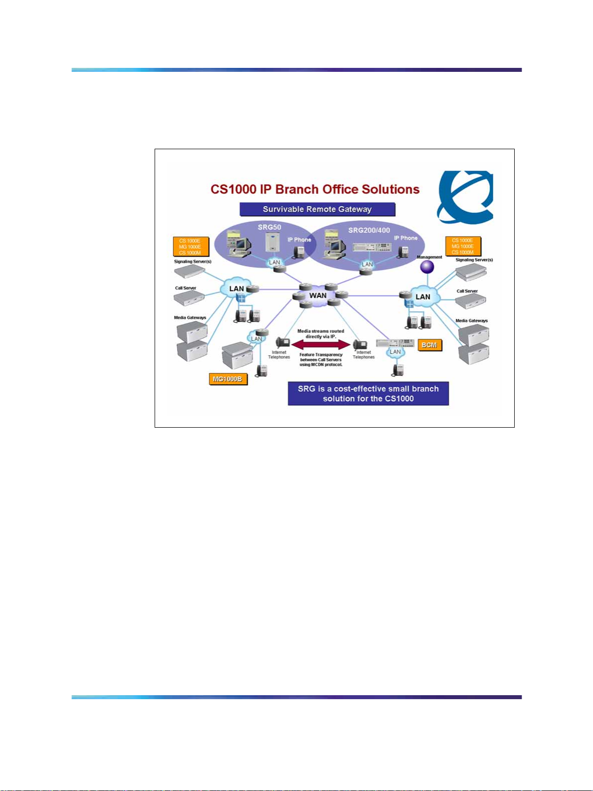
Survivable Remote Gateway
The Survivable Remote Gateway (SRG) extends the desktop feature and
user interface of the CS 1000 to remote IP branch office users and gives
them full access to the same applications as the main site. CallPilot, Contact
Center Management Server (CCMS), and other central applications are
shared by remote users to deliver state-of-the-art features and functionality
to small remote offices.
11
SRG 50 Release 2.0 provides the following:
•
extends the supported number of survivable IP users from 32 to 80
•
extends support for the IP Phone 1120E, IP Phone 1140E, IP Audio
Conference Phone 2033, and WLAN 2212
See "Supported IP Phones" (page 16) for a complete list of supported
IP Phones.
•
supports H.323 and SIP Trunking to the CS 1000 main office
•
supports analog devices, such as fax machines and terminals but are
limited in number and limited to basic access
Copyright © 2005-2007, Nortel Networks
.
Nortel Communication Server 1000
Main Office Configuration Guide for SRG 50
NN43001-307 02.02 Standard
Release 5.0 3 December 2007
Page 12

12 Description
SRG 50 Release 3.0 provides the following:
•
extends support for the IP Phone 1110
See "Supported IP Phones" (page 16) for a complete list of supported
IP Phones.
•
evolves the SIP trunk to support a standard SIP Trunk interface
•
supports On-site Notification
Table 1
Supported software at the branch office
IP branch office
solution
SRG 1.0
SRG 50 Release 1.0
SRG200/400 Release
1.5
SRG 50 Release 2.0
Survivable
users
up to 90
up to 32
up to 90
up to 80
Server
support
Succession 3.0
CS 1000
Release 4.0
CS 1000
Release 4.5
Succession 3.0
CS 1000
Release 4.0
CS 1000
Release 4.5
Succession 3.0
CS 1000
Release 4.0
CS 1000
Release 4.5
CS 1000
Release 5.0
Succession 3.0
CS 1000
Release 4.0
CS 1000
Release 4.5
CS 1000
Release 5.0
Feature description
VoIP and Application Gateway
Local Mode = Basic telephony
features
VoIP and Application Gateway
Local Mode = Basic telephony
features
A more cost effective small branch
office solution.
Provides H.323 trunking.
For more information, see CS
1000 Main Office Configuration
Guide for SRG 50 (553-3001-207).
VoIP and Application Gateway
Local Mode = Basic telephony
features
Feature Parity with SRG 50,
new OS, and extended IP Phone
support.
Provides H.323 trunking.
For more information, see Main
Office Configuration Guide for
SRG 200/400 Release 1.5
(NN43001-308).
VoIP and Application Gateway
Local Mode = Basic telephony
features
Extends IP Phone support and
survivable IP users from 32 to 80.
Provides H.323 and SIP trunking.
For more information, see CS
1000 Main Office Configuration
Guide for SRG 50 (553-3001-207).
Copyright © 2005-2007, Nortel Networks
.
Nortel Communication Server 1000
Main Office Configuration Guide for SRG 50
NN43001-307 02.02 Standard
Release 5.0 3 December 2007
Page 13

Survivable Remote Gateway 13
IP branch office
solution
SRG 50 Release 3.0
MG 1000B
MG 1000E
The SRG is implemented on a BCM 50 platform and is connected to a CS
1000 at the main office through Virtual Trunks over a reliable IP WANaccess
facility. This configuration allows the call processing for the IP Phones at
the SRG site to be centralized at the main office. The Call Server at the
main office provides the call processing for the IP Phones registered to
both the main office and branch offices. The SRG provides call processing
functionality to phones in local mode and local analog devices. The SRG
supports business continuity and call failover through digital and analog
trunk access to the local Public Switched Telephone Network (PSTN).
Survivable
users
up to 80
up to 400
up to 400
Server
support
CS 1000
Release 5.0
Succession 3.0
CS 1000
Release 4.0
CS 1000
Release 4.5
CS 1000
Release 5.0
CS 1000
Release 5.0
Feature description
VoIP and Application Gateway
Local Mode = Basic telephony
features
Extends IP Phone support to
include the IP Phone 1110.
Supports On Site Notification for
E-911 calls.
Provides H.323 and SIP trunking.
100% CS 1000 feature and
application redundancy in
survivable mode. Designed and
positioned for larger IP branch
offices.
Provides H.323 and SIP trunking.
Provides survivability with the
addition of Call Processor Pentium
Mobile (CP PM).
In order for devices in the CS 1000 network to access analog devices at
the SRG or to access the PSTN at the SRG, virtual trunks are used over
the LAN/WAN.
If the main office fails to function, or if there is a network/WAN outage, the
SRG automatically switches to Local mode and provides basic telephony
service to the phones located at the branch office. This enables the IP
Phones to survive the outage between the branch office and the main office.
To ensure proper operation of the SRG solution it must be configured to
support a common dialing plan with the CS 1000 main office. Any other
configuration is not guaranteed to work reliably. Since the Call Server and
the SRG handle dialing slightly differently, ensure that any settings you use
for the main office that need to interact with the SRG, can be accommodated
by the SRG call processing.
Copyright © 2005-2007, Nortel Networks
.
Nortel Communication Server 1000
Main Office Configuration Guide for SRG 50
NN43001-307 02.02 Standard
Release 5.0 3 December 2007
Page 14
14 Description
Figure 1 "SRG network" (page 14) shows the networking among the main
office, SRG, and IP Phones.
Figure 1
SRG network
Main office hardware description
The main office must be one of the following systems:
•
CS 1000E
•
CS 1000M Cabinet
•
CS 1000M Chassis
•
CS 1000M HG
•
CS 1000M SG
•
CS 1000M MG
Throughout this document, references to CS 1000 systems encompass
all CS 1000 system types.
The diagrams throughout this documentation show a CS 1000E main
office. All of the systems appearing in the list perform identical main office
functions as far as the SRG is concerned. For information about the SRG,
see SRG50 Configuration Guide (NN40140-500).
Nortel Communication Server 1000
Main Office Configuration Guide for SRG 50
NN43001-307 02.02 Standard
Copyright © 2005-2007, Nortel Networks
.
Release 5.0 3 December 2007
Page 15

Signaling Server
The following Signaling Servers are available for CS 1000 Release 5.0 :
•
ISP1100
•
HP-DL320-G4
•
IBM-X306m
•
Common Processor Pentium Mobile (CP PM)
The Signaling Server is required at the main office only. It provides the
following functions:
•
Terminal Proxy Server (TPS)
The TPS provides a connection from the IP Phones to the Call Server
and a connection from a Virtual Trunk to the Call Server.
•
H.323 Gateway (Virtual Trunk)
•
SIP Gateway (Virtual Trunk)
•
CS 1000 Element Manager Web Server and Network Routing Service
(NRS)
Main office hardware description 15
•
NRS, consisting of:
— SIP Redirect Server NRS
— H.323 Gatekeeper
— Network Connection Service (NCS)
•
Personal Directory
A second Signaling Server can be used to provide redundancy in the case
of a failure in the primary Signaling Server at the main office.
A similar function to the Signaling Server is used at the SRG when the
phones are in local mode.
The Signaling Server supports en bloc signaling which is standard on the
Signaling Server.
For more information about the Signaling Server, see Signaling Server
Installation and Commissioning (NN43001-312). For more information
about H.323 and overlap signaling, see IP Peer Networking Installation
and Commissioning (NN43001-313).
Network Routing Services
•
The Network Routing Service (NRS) application provides network-based
routing, combining the following into a single application:
Copyright © 2005-2007, Nortel Networks
.
Nortel Communication Server 1000
Main Office Configuration Guide for SRG 50
NN43001-307 02.02 Standard
Release 5.0 3 December 2007
Page 16

16 Description
•
H.323 Gatekeeper— provides central dialing plan management and
routing for H.323-based endpoints and gateways.
•
SIP Redirect Server NRS — provides central dialing plan management
and routing for SIP-based endpoints and gateways. SIP Trunks are
used for Voice packet traffic alone.
• NRS Database— stores the central dialing plan in XML format for the
H.323 Gatekeeper, and the SIP Redirect Server. The H.323 Gatekeeper
and the SIP Redirect Server accesses this common endpoint and
gateway database.
•
Network Connect Server (NCS) — used only for Media Gateway
Controller (MGC) based MG 1000B, SRG, Geographic Redundancy,
and Network-wide Virtual Office solutions. The NCS allows the Line
TPS (LTPS) to query the NRS.
•
NRS Manager web interface— the NRS provides its own web interface
to configure the H.323 Gatekeeper, SIP Redirect Server, and the NCS.
The NRS application provides routing services to H.323 devices and
SIP-compliant devices. The H.323 Gatekeeper can be configured to
support H.323 routing services, while the SIP Redirect Server NRS can be
configured to support SIP routing services. The H.323 Gatekeeper and the
SIP Redirect Server NRS can reside on the same Signaling Server.
Each system in an IP Peer network must register to the NRS. The NRS
software identifies the IP addresses of systems based on the network-wide
numbering plan. NRS registration eliminates the need for manual
configuration of IP addresses and numbering plan information at every site.
When configuring the NRS it is necessary to enable the NCS. Ensure that
the check box “Network Connection Server enabled” is checked in the NRS
configuration window of CS 1000 Element Manager.
For information about configuring the NRS, see IP Peer Networking
Installation and Commissioning (NN43001-313).
Supported IP Phones
Table 2 "IP Phone support " (page 16) shows the supported IP Phones
for each software release.
Table 2
IP Phone support
IP Phone Release 1.0 Release 2.0 Release 3.0
IP Phone 2001 Supported Supported Supported
Copyright © 2005-2007, Nortel Networks
.
Nortel Communication Server 1000
Main Office Configuration Guide for SRG 50
NN43001-307 02.02 Standard
Release 5.0 3 December 2007
Page 17

Main office requirements 17
IP Phone 2002 Supported Supported Supported
IP Phone 2004 Supported Supported Supported
IP Phone 2007 Supported Supported Supported
IP Audio Conference Phone 2033 Supported Supported Supported
IP Softphone 2050 Supported Supported Supported
IP Phone 1110 Not supported Not supported Supported
IP Phone 1120E Not supported Supported Supported
IP Phone 1140E Not supported Supported Supported
IP Phone 1150E Not supported Not supported Not supported
Mobile Voice Client (MVC) 2050 Supported Supported Supported
Analog (500/2500-type) telephones Supported Supported Supported
WLAN Handset 2210 Supported Supported Supported
WLAN Handset 2211 Supported Supported Supported
WLAN Handset 2212 Not supported Supported Supported
WLAN Handset 6120 Not supported Not supported Not supported
WLAN Handset 6140 Not supported Not supported Not supported
Throughout this document, the IP Phones are referred to collectively as
IP Phones.
Main office requirements
The branch office running SRG Release 3.0 requires the following at the
main office:
•
CS 1000 hardware, running CS 1000 Release 4.0, CS 1000 Release
4.5, orCS 1000 Release 5.0 .
•
Configure at least one of the following packages for IP Peer Networking:
— H.323 Virtual Trunk (H323_VTRK) package 399
— SIP Gateway and Converged Desktop Package (SIP) package 406
•
The main office must have a software Service Level of 2 or higher to
work with the branch office.
•
Ensure that you have ordered enough IP user and Virtual Trunk licenses
at the main office to support the SRG 50 or the capacity of your branch
office.
The two different IP user licenses at the main office are:
— Basic IP License for the IP Phone 2001, IP Audio Conference Phone
2033, and IP Phone 1110
Copyright © 2005-2007, Nortel Networks
.
Nortel Communication Server 1000
Main Office Configuration Guide for SRG 50
NN43001-307 02.02 Standard
Release 5.0 3 December 2007
Page 18

18 Description
— IP User License for the IP Phone 2002, IP Phone 2004, IP Phone
2007, IP Phone 1120E, IP Phone 1140E, IP Softphone 2050, Mobile
Voice Client (MVC) 2050, WLAN Handset 2210, WLAN Handset
2211, and WLAN Handset 2212
The main office requires the following software packages to support
the specified Basic Network features. See Basic Network Feature
Fundamentals (NN43001-579) for more information about these features.
•
Network Call Back Queuing (MCBQ) package 38. This package is
required for SRG IP Phones to invoke any queuing feature or ringback
when free.
•
Network Speed Call (NSC) package 39. This package is required for
SRG IP Phones to invoke the Network Speed Call feature.
The main office requires the following software packages to support the
specified ISDN Primary Rate Interface features. See ISDN Primary Rate
Interface Fundamentals (NN43001-569) for more information about these
features.
•
Network Attendant Service (NAS) package 159. This package is
required for analog (500/2500-type) telephones in the branch office
to access attendant services when the attendant is configured on the
main office.
•
Network Message Services (NMS) package 175. This package is
required for analog (500/2500-type) telephones in the branch office to
share the voice mail system in the main office. For any configurations
using centralized CallPilot on the main office with one or more branch
offices in separate time zones, the NMS package is required at the main
office for the branch IP Phones.
Optional features to enhance SRG functionality
•
Network Alternate Route Selection (NARS) package 58. See Basic
Network Feature Fundamentals (NN43001-579).
•
Overlap Signaling (OVLP) package 184. This package is optional; it is
required for overlap signaling. It is packaged with H.323 Virtual Trunk
(H323_VTRK) package 399.
•
Emergency Services Access (ESA) package 329. This package is
optional; it is required only to receive 911/ESA features in North
American and some Caribbean and Latin American (CALA) markets.
See Emergency Services Access Fundamentals (NN43001-613).
•
Virtual Office (VIRTUAL_OFFICE) package 382. This package is
optional; it is required only for Virtual Office functionality.
Copyright © 2005-2007, Nortel Networks
.
Nortel Communication Server 1000
Main Office Configuration Guide for SRG 50
NN43001-307 02.02 Standard
Release 5.0 3 December 2007
Page 19

Normal Mode and Local Mode overview 19
•
Network Signaling (NSIG) package 37. This package is optional for
SRG IP Phones to access set-based Network Class of Service (NCOS)
features.
•
Adaptive Network Bandwidth Management package 407.
• Alternative Call Routing for Network Bandwidth Management.
Forsoftware and hardware requirements for SRG, see SRG50 Configuration
Guide (NN40140-500).
Normal Mode and Local Mode overview
Normal Mode and Local Mode overview provides a description of the
following sections:
•
Normal Mode
•
Local Mode
•
Survivability
•
Recovery to Normal Mode
• Local Mode operation
•
Virtual trunks
Normal Mode
IP Phones that are physically located at the SRG but are registered with the
main office are operating in Normal Mode. In Normal Mode, the main office
provides centralized call processing to all applications transparently to all
IP Phones at the Branch Office. All IP Phones at the Branch, in Normal
Mode, are registered to the main office TPS and are controlled by the Call
Server at the main office.
Users of the SRG IP Phones receive the features, applications, key
layout, and tones of the main office Call Server. This provides feature and
application transparency between the branch office and the main office.
Local Mode
Users at the branch office may be in Local Mode, or survivable mode for
two different reasons:
1. IP Phone has just booted up.
2. IP Phone cannot communicate to the main office because of a WAN
failure or a failure of the main office components.
Copyright © 2005-2007, Nortel Networks
.
Nortel Communication Server 1000
Main Office Configuration Guide for SRG 50
NN43001-307 02.02 Standard
Release 5.0 3 December 2007
Page 20

20 Description
ATTENTION
When a telephone or trunk in the main office calls an SRG IP Phone that has
switched to Local Mode due to WAN failure, the call is treated according to the
main office call redirection configuration (such as forwarding to voice mail or
continuous ringback).
In the event that the IP Phones at the branch office lose the connection to
the main office CS 1000 call server for any reason (WAN failure, main office
call server failure, main office Signaling Server failure), the SRG 50 reverts
to Local Mode automatically. Essentially, when VoIP connectivity is lost,
each IP Phone loses its Reliable UDP (RUDP) connection with the main
office Terminal Proxy Server (TPS). The IP Phones at the branch office
reboot and reregister to the SRG 50, placing them in Local Mode.
After this occurs, the IP Phones displays an indication on the display area
that the set is in Local Mode of operation. This display is configurable by
installers to meet local language and usage norms.
In Local Mode, the IP users connected at the branch office are under the
control of the SRG 50 call services. As such, the normal main office call
server features are not available. The SRG 50 offers a basic feature set
when in Local Mode which allows IP Phones to continue to make and
receive calls internally within the branch office and over the provisioned
local PSTN interfaces. Basic services, such as transfer, last number redial,
and single key access through the PSTN to a centralized voice messaging
system are supported. Local PSTN access and local Emergency Services
access is also supported. No local applications or Business Communication
Manager features are supported in Local Mode operation.
Analog devices continue to be under the control of the SRG 50 system. It
is the intent of Local Mode to provide continued access to the PSTN for
critical calls and emergency services.
In Local Mode, since the SRG 50 handles all call processing, calls
between two IP phones at the SRG 50 are handled locally as a simple
station-to-station call. When an IP Phone initiates a local PSTN call, the
SRG 50 routes the call to a trunk that is connected to the local PSTN.
Incoming DID calls are also handled by the SRG 50 and terminated on
the appropriate IP Phone.
In the event of a WAN failure, in Local Mode, the IP Phones do not have
access to the main office network over the VoIP trunks. If the appropriate
alternate routes are configured, calls will be routed to the main office or
other branch offices using the available PSTN trunks.
Copyright © 2005-2007, Nortel Networks
.
Nortel Communication Server 1000
Main Office Configuration Guide for SRG 50
NN43001-307 02.02 Standard
Release 5.0 3 December 2007
Page 21

Normal Mode and Local Mode overview 21
While in Local Mode, the SRG 50 system continues to monitor for a main
office CS 1000 heartbeat signal, and once detected, automatically redirects
phones on an individual basis back to Normal Mode of operation. If a
call is active, the SRG waits until the call is completed before redirecting
the phones; calls in progress are not interrupted. This switch-over occurs
almost immediately once the SRG determines that an individual phone
can be redirected. This reinstates the CS 1000 normal user interface and
feature set for the IP Phone user, on a user by user basis.
The SRG 50 system implements the same interface used by the MG 1000B
system to interact with the main office CS 1000 system. This allows the
main office to identify attached clients and the local PSTN as branch office
entities, enabling proper operation of dial plans and E911 access.
In Local Mode, devices that are physically located at the branch office, that
are controlled by the local system and receive a basic telephony feature
set, provide business continuity for the branch office during the WAN or
system failure. The SRG supports a main office heartbeat or reliable UDP
signaling which automatically reregisters users once WAN or system failure
has recovered.
For information about the features supported in Local Mode, see SRG50
Configuration Guide (NN40140-500).
Survivability
SRG is specifically designed to provide automatic survivability against WAN
failure, main office Call Server failure, main office Signaling Server failure,
and Gatekeeper failure.
SRG supports the Geographic Redundancy feature. For further information
about Geographic Redundancy, see System Redundancy Fundamentals
(NN43001-507).
In the event of a WAN failure, the SRG IP Phones lose communication
with the main office. This causes the SRG IP Phones to reset and register
with the SRG. The IP Phones then operate in Local Mode, providing
basic telephony services delivered by the local SRG system. For further
information about services and features supported on the SRG, see SRG50
Configuration Guide (NN40140-500).
If the main office Call Server fails and call processing services are provided
by an Alternate Call Server, the SRG IP Phones reset and reregister with
the Alternate Call Server and receive call processing services from it. If no
Alternate Call Server is available, the SRG IP Phones go to Local Mode
while the SRG attempts to find an Alternate Call Server by way of the NCS.
Copyright © 2005-2007, Nortel Networks
.
Nortel Communication Server 1000
Main Office Configuration Guide for SRG 50
NN43001-307 02.02 Standard
Release 5.0 3 December 2007
Page 22

22 Description
If the main office Signaling Server fails and an Alternate Signaling Server
is available, the SRG IP Phones reset and reregister with the SRG. The
SRG will then query the NCS for the Alternate Signaling Server IP address.
The SRG will redirect the IP Phone to the Alternate Signaling Server and
continue to receive call processing services from the main office Call Server.
If no Alternate Signaling Server is available, the SRG IP Phones reset and
register with the SRG in Local Mode.
When an IP Phone at the SRG first boots up, the IP Phone attempts
to communicate with the SRG. After communication with the SRG is
established, the SRG redirects the IP Phone to the main office. When
the SRG IP Phone attempts to register with the main office, the SRG first
queries the Primary NCS for the main office Virtual Trunk node IP address
to redirect the IP Phone. If the Primary NCS is down or unreachable, the
SRG queries the Alternate NRS (H.323 Gatekeeper/SIP Redirect Server),
if one is specified. If it receives a positive response, the SRG IP Phone is
redirected to the specified main office. Otherwise, if neither a Primary or
an Alternate NRS (H.323 Gatekeeper/SIP Redirect Server) is available,
the SRG IP Phone remains in Local Mode, and receives call processing
services from the SRG until communication can be reestablished.
SRG IP Phones in Normal Mode remain registered with the main office
if the Primary NCS fails and no Alternate NCS is available. They can
call any main office telephone or IP Phones in Normal Mode in other
branch offices. However, they cannot call any SRG analog (500/2500-type)
telephones or any external numbers through the SRG trunks because an
H.323 Gatekeeper/SIP proxy server, which could route call properly in case
of an NRS failure, is not available.
Recovery to Normal Mode
After communication is reestablished with the main office call server, all IP
Phones at the branch office that are in Local Mode automatically redirect
and reregister to the main office and return to Normal Mode operation.
IP Phones that were busy at the time communication was reestablished
complete the call in Local Mode, and then reregister with the main office
after the call is complete.
Local Mode operation
When an SRG IP Phone is in Local Mode, the user has full access to
the services configured at the SRG (analog devices or analog or digital
trunks) and to other IP Phones registered to the SRG. In Local Mode,
the IP Phones can make local calls to other IP Phones and other analog
(500/2500-type) telephones at the branch office. They can also be used to
make outgoing PSTN calls and receive incoming calls as usual. SRG IP
Phones can access the main office IP Phones or other branches by routing
through the local PSTN.
Copyright © 2005-2007, Nortel Networks
.
Nortel Communication Server 1000
Main Office Configuration Guide for SRG 50
NN43001-307 02.02 Standard
Release 5.0 3 December 2007
Page 23

Testing the phone in Local Mode
From Normal Mode, the branch user has the option of going to Local Mode
manually using the Test Local Mode feature, or when the telephone is
power-cycled. The test can be performed by the user at any time and
does not require a password. This test is invoked from any IP Phone at
the branch office.
Nortel recommends testing Local Mode operation after changing the
provisioning for a telephone on the SRG.
To ensure that users do not forget to resume Normal Mode operation, the
SRG redirects the telephone to the main office to return the telephone to
Normal mode. This occurs if the telephone remains registered to the SRG
in Test Local Mode for ten minutes (default setting). Alternatively, the user
can press the Quit key on the phone to return to Normal Mode.
For further information about Local Mode functionality for SRG, see SRG50
Configuration Guide (NN40140-500).
Virtual Trunks
In order for endpoints in the CS 1000 network to access endpoints in local
mode at the SRG or to access the PSTN at the SRG, Virtual Trunks are
used over the LAN/WAN.
Normal Mode and Local Mode overview 23
Virtual Trunks are software components that provide the trunking features
of the Meridian Customer-Defined Network (MCDN) feature set. Access
to PSTN digital or analog trunks at the branch office occurs through the
MCDN Virtual Trunk.
Virtual Trunks are sometimes referred to as SIP or H.323 Virtual Trunks. In
the SRG50 Configuration Guide (NN40140-500), Virtual Trunks are referred
to as IP Trunks.
For more information about Virtual Trunks, see IP Peer Networking
Installation and Commissioning (NN43001-313).
IP Phone calls
When an IP Phone calls another IP Phone, each telephone receives the
address of the other to exchange media directly between the telephones.
When in Normal Mode, an SRG IP Phone calling a main office IP Phone
does not require any trunking to set up the call. However, LAN/WAN
bandwidth is used to provide a media path for the call. For more information
on Direct IP media path functionality, see IP Peer Networking Installation
and Commissioning (NN43001-313).
Copyright © 2005-2007, Nortel Networks
.
Nortel Communication Server 1000
Main Office Configuration Guide for SRG 50
NN43001-307 02.02 Standard
Release 5.0 3 December 2007
Page 24

24 Description
Bandwidth Management Overview
For a complete overview of Bandwidth Management, see the Converging
the Data Network with VoIP (NN43001-260) and for details on configuration,
see "Bandwidth Management" (page 95).
Network Bandwidth Management
Network Bandwidth Management allows for a limit to be placed on the
amount of interzone bandwidth allowed between IP Phones in Normal Mode
at the SRG and the rest of the CS 1000 network.
As well, it allows for the selection of interzone bandwidth codecs for calls
between the IP Phones in Normal Mode and the rest of the CS 1000
network.
Adaptive Network Bandwidth Management
Adaptive Network Bandwidth Management allows the system to dynamically
react to Quality of Service (QoS) degradation and take corrective action.
Network Bandwidth Management Zones
A zone is a collection of IP Phones that:
•
share similar IP bandwidth restrictions
•
are geographically close to one another
•
are all in the same time zone
•
are all in the same PSTN dialing plan
The Network Bandwidth Management Zone is made up of the VPNI and
the zone. The VPNI of the main office and all the SRG associated with it
must be the same.
Each SRG must have its own unique zone number and configured in the
main office Call Server and the SRG.
Throughout this document, the term zone is defined as a Bandwidth Management
Zone, not an NRS (H.323 Gatekeeper) Zone. See "Bandwidth Management"
(page 95).
Time of Day
Because the SRG IP Phones, in Normal Mode, receive their clock
information from the main office, which may be located in a different time
zone, the main office must be able to provide a different time of day for
these phones.
ATTENTION
Copyright © 2005-2007, Nortel Networks
.
Nortel Communication Server 1000
Main Office Configuration Guide for SRG 50
NN43001-307 02.02 Standard
Release 5.0 3 December 2007
Page 25

The time zone of the SRG is configured with the SRG zone at the main
office. The time zone adjusts the main office time for display at the SRG.
SRG phones then display the correct time of the SRG, rather than that of
the main office. For any configurations using centralized Call Pilot on the
main office with one or more branch offices in separate time zones, the
NMS package is required at the main office for the branch IP Phones.
SRG IP Phone to local PSTN calls
When an SRG IP Phone in Normal Mode dials a local PSTN number, the
call is processed by the main office Call Server. The dialed digits are
modified according to the dialing plan information configured in the zone for
the SRG IP Phone.
The call is configured to be routed over the Virtual Trunk to the branch
office. The SRG then tandems the call to the local PSTN. Likewise, long
distance calls can also be configured.
If you use one Access Code for both local and long distance calls, and that
Access Code is associated with a branch office zone, all calls (local and
long distance) are routed through the SRG
Bandwidth Management Overview 25
IP Phone to analog (500/2500-type) telephone calls
When an IP Phone in Normal Mode at the SRG calls an analog
(500/2500-type) telephone of the same SRG, the call is processed at the
main office Call Server. A Virtual Trunk route is selected according to the
digits dialed. The call is routed over a Virtual Trunk to the branch office. The
SRG processes the incoming Virtual Trunk call and terminates it to the
local analog (500/2500-type) telephone. Since this is a call between IP and
circuit-switched devices, a DSP resource on a Media Card is allocated and
connected to the analog (500/2500-type) telephone. The IP address of the
DSP resource is returned to the main office Call Server so a direct media
path between the IP Phone and the DSP resource can be set up when the
call is established. See IP Peer Networking Installation and Commissioning
(NN43001-313) for details.
Conference calls
When an SRG user initiates a conference call, the conference facilities of
the main office are used. This means that in a conference among three
SRG users, the LAN/WAN bandwidth of three media paths is used. The
calls are controlled by the main office, except in Local Mode. In Local Mode,
SRG users do not have access to conferencing.
Networking consideration
A fault condition can occur if IP Phones use a different route to the main
office than that used by the SRG.
Copyright © 2005-2007, Nortel Networks
.
Nortel Communication Server 1000
Main Office Configuration Guide for SRG 50
NN43001-307 02.02 Standard
Release 5.0 3 December 2007
Page 26

26 Description
Capacity
CAUTION
Service Interruption
If the network is planned so that IP Phones use a different route
to the main office than that used by the SRG, a fault condition
can occur. When the SRG can reach the main office but the IP
Phone cannot ping the main office due to a network outage, an
IP Phone registration can force the telephone into a cycle of
registering locally, being redirected to the main office, rebooting,
and then registering locally again. When this cycle occurs, further
diagnose the network outage.
Each CS 1000 main office can support up to 255 branch offices, which can
be made up of any combination SRG and MGC based MG 1000B. SRG 50
Release 2.0 and later supports up to 80 survivable IP users. However,
since all IP Phones register with the main office, the governing factor is the
maximum number of IP Phones that can be supported at the main office.
This means the total number of IP Phones in all offices can be no greater
than the capacity of the main office. See one of the following documents to
determine the total number of phones your system can support:
•
CommunicationServer 1000E Planning and Engineering (NN43041-220)
• Communication Server 1000M and Meridian 1 Large System Planning
and Engineering (NN43021-220)
Virtual Trunks capacity
The SRG capacity to support a number of simultaneous calls depends on
the specific codec type used and the available bandwidth.
If both the intrazone and interzone codes are configured as Best Quality
(G.711), the SRG supports up to 24 Virtual Trunks (H.323 or SIP),
otherwise, only 15 Virtual Trunks (H.323 or SIP) are supported.
In Normal Mode, the codec selection used is controlled by specific
programming of the CS 1000.
In Local Mode, if the WAN has failed, Virtual Trunks between the SRG
and CS 1000 cannot be established. However, the SRG will continue to
convert calls from IP terminals for communication through the PSTN. Nortel
recommends you use G.711 codec.
Copyright © 2005-2007, Nortel Networks
.
Nortel Communication Server 1000
Main Office Configuration Guide for SRG 50
NN43001-307 02.02 Standard
Release 5.0 3 December 2007
Page 27

Branch office dialing plan
Since IP Phone users can be located at a branch office equipped with an
SRG, the routing of calls to the local gateway is important (especially when
toll charges apply to calls made from the central Call Server that controls
the telephone). The administrator can configure digit manipulation through
zone attributes for IP Phones to select a main office or branch office that
provides PSTN access local to the destination of the call.
Calls from the PSTN to users within the network can be routed with the
various ESN numbering plan configurations.
To access local PSTN resources, outgoing calls can be routed using ESN
as well as zone parameters that enable digit insertion. The zone parameters
force calls made by an SRG user to be routed to the desired local PSTN
facilities.
Outgoing calls can include local and, optionally, long distance calls.
Branch office dialing plan 27
ATTENTION
Nortel recommends that the Branch User ID (BUID) be the same at the
branch office as the DN at the main office. A BUID has a maximum of 15
digits. Under the recommended Coordinated Dialing Plan (CDP), the BUID
can be an extension (for example, 4567). Under the Uniform Dialing Plan
(UDP), the BUID is the user main office DN, the Location Code (LOC), plus
the Access Code (for example, 6 343-5555). The main office DN must be
an ESN compliant DN. See "ESN Access Codes" (page 27).
The SRG only supports only one dialing plan option at a time. CDP and
UDP dialing plan options cannot be configured at the same time in the
same system.
For more information about dialing plans and configuration, see "Dialing
Plan configuration" (page 43). For more information about the branch
office dialing plan, see CS 1000 Main Office Configuration for SRG50
(NN43001-307).
ESN Access Codes
ESN data is configured with two Access Codes, called AC1 and AC2.
AC1 normally applies to long distance calls, whether placed on or off the
customer’s private network (for example, dialing 6). AC2 normally applies to
local calls (for example, 9). For more information, see Electronic Switched
Network Reference—Signaling and Transmission (NN43001-280).
Copyright © 2005-2007, Nortel Networks
.
Nortel Communication Server 1000
Main Office Configuration Guide for SRG 50
NN43001-307 02.02 Standard
Release 5.0 3 December 2007
Page 28

28 Description
Music on Hold
For SRG users in Normal Mode, the main office provides music to the user
if Music on Hold is provisioned. The use of the G.729A/AB codec between
the main office and the branch office can impact the music quality.
ATTENTION
G.723 codec is not supported on SRG 50.
Branch office and SRG 50 terminology
Table 3 "Branch office and SRG 50 terminology" (page 28) lists
configuration-related terms and contexts where branch office and SRG
50 terminology differ.
Table 3
Branch office and SRG 50 terminology
Term or context Branch office
dialing plan on-net/off-net dialing Private/Public network dialing
routing distant steering codes (DSC),
Trunk steering codes (TSC), Local
steering codes (LSC)
Digit manipulation table dial-out digits (routing)
alternate routing
selection
Type of number CDP/UDP/TNDN CDP/UDP/no equivalent
Numbering Plan ID ISDN/Telephony
User ID BUID BUID
Trunks public exchange PSTN
access codes (SRG 50:
destination codes)
Facility Restriction Level (FRL) scheduled call routing
(E.164),Private, Telephony
(E.163), Telex, (F.69), Data
(X.121), National Standard
bandwidth management zone Zone ID
virtual trunk IP trunk
7 = system trunk access
SRG 50
call routing, destination codes, line
pool access codes
Private
7 = not assigned
8 = Basic Alternate Route Selection
(BARS)/Network Alternate Route
Selection (NARS)
9 = public exchange access
Copyright © 2005-2007, Nortel Networks
.
8 = not assigned
9 = line pool A access code
Nortel Communication Server 1000
Main Office Configuration Guide for SRG 50
NN43001-307 02.02 Standard
Release 5.0 3 December 2007
Page 29

Limitations 29
Term or context Branch office
Network Class of Service (NCOS)
telephone numbers
(internal, not PSTN)
DN DN
Limitations
The following is a list of limitations for SRG 50 Release 3.0:
•
When an IP Phone is in Local Mode, the SRG 50 does not provide all
the features as those provided by the CS 1000 main office. In Local
Mode, the SRG provides basic features, basic call handling, and basic
routing capabilities only.
•
When an IP Phone is in Local Mode, the SRG 50 does not support IP
Phone Key Expansion Module or Expansion Module for IP Phone 1100
Series.
•
You cannot configure the BUID and MOTN using the IP Phone.
Configure the BUID and MOTN using SRG Element Manager.
•
The SRG and the CS 1000 are configured separately. There is no
single management paradigm or application to update both the CS 1000
and the SRG. Use Element Manager to configure the SRG, and use
standard configuration tools to configure the CS 1000.
SRG 50
•
Virtual Office Login is not supported in Local Mode.
• Language, Volume, and Contrast settings in the SRG are not
synchronized with the CS 1000 settings which causes a potential
mismatch in settings between Normal Mode and Local Mode.
•
Language options available on the CS 1000 may not be available on
the SRG.
•
For the CS 1000 Release 5.0 Alternate Routing for Network Bandwidth
Management feature, the SRG does not support an automatic
redirection of IP trunk calls through the PSTN when such calls are
blocked by the CS 1000 due to bandwidth availability.
•
Multiple ESDN is not supported.
•
VLAN tagging is not supported. However, VLAN tagging is achieved
by using an external router.
•
Active Call Failover is not supported.
•
SIP trunks are used only for voice packet traffic alone. H.323 trunking
is used for main office and Gatekeeper/NRS discovery, polling of WAN
link, as well as voice traffic.
Copyright © 2005-2007, Nortel Networks
.
Nortel Communication Server 1000
Main Office Configuration Guide for SRG 50
NN43001-307 02.02 Standard
Release 5.0 3 December 2007
Page 30

30 Description
Copyright © 2005-2007, Nortel Networks
.
Nortel Communication Server 1000
Main Office Configuration Guide for SRG 50
NN43001-307 02.02 Standard
Release 5.0 3 December 2007
Page 31

Setting up the main office
Contents
This section contains the following topics:
•
"Introduction" (page 31)
•
"SRG information required by the main office" (page 31)
•
"Main office information required by the SRG" (page 32)
•
"Zone parameters" (page 34)
•
"Branch office IP Phone configuration at the main office" (page 38)
•
"SIP IP Trunks configuration at the main office" (page 40)
Introduction
This section describes the following information required to configure the
main office:
•
SRG information required by the main office
31
•
Main office information required by the SRG
•
Zone parameters
•
IP Phone passwords and parameters
•
Branch office IP Phone configuration
For more information on main office configuration, see IP Peer Networking
Installation and Commissioning (NN43001-313).
SRG information required by the main office
The main office administrator must gather information about the SRG
system. The following information is required:
•
an inventory of IP Phones that will be installed on the SRG so the
administrator knows what type of telephone to assign to each main
office terminal record
Nortel Communication Server 1000
Main Office Configuration Guide for SRG 50
NN43001-307 02.02 Standard
Copyright © 2005-2007, Nortel Networks
.
Release 5.0 3 December 2007
Page 32

32 Setting up the main office
•
information which allows the administrator to create an NCS (H.323
Gatekeeper or SIP Redirect Server) entry for the SRG
•
if using advanced routing, such as tandem dialing between systems,
local PSTN number for the SRG and the internal SRG routing codes
that will allow the main office to connect to the SRG and to tandem over
the SRG PSTN lines, is required
Use Table 4 "SRG information required for the main office configuration"
(page 32) to record the information before setting up the SRG on the main
office server.
Table 4
SRG information required for the main office configuration
SRG parameters
SRG public IP address
H.323 ID (required for requests to NCS)
Each H.323 ID in the node should match SIP endpoint name
for this system in pure SIP environment.
List of types and number of IP Phones
Telephone types are hard-coded to the Terminal Numbers
(TN) and the main office. Therefore, install the same type of IP
Phones to the coordinating record on the SRG.
PSTN number to dial into the SRG (in local mode)
Destination codes (steering codes) to route the main office calls
to the SRG and out through the SRG PSTN lines
IP Ports that affect SRG traffic with the main office and have
been assigned firewall filters
For further information on port configuration, see Converging
the Data Network with VoIP (NN43001-260) or SRG50
Configuration Guide (NN40140-500).
Main office information required by the SRG
The main office administrator must supply numerous main office settings to
the SRG installer so that the SRG can be efficiently configured. In addition,
the main office administrator needs to supply the following information:
•
a list of the terminal record numbers (TN)
•
a list of BUID (Prime DN)
•
if using advanced routing, such as tandem dialing between systems,
main office routing (steering) codes, are required
Copyright © 2005-2007, Nortel Networks
.
Nortel Communication Server 1000
Main Office Configuration Guide for SRG 50
NN43001-307 02.02 Standard
Release 5.0 3 December 2007
Page 33

Main office information required by the SRG 33
Use Table 5 "Main office interoperation information" (page 33) to record
main office information required by the SRG.
Table 5
Main office interoperation information
Main office components Information about this system
Main office IP network information:
Main office call server type S1000 (default)
Primary network connect server address
Alternate network connect server
Network Connect server port
Trunk/telephony preferred codecs and jitter
buffers listed in order of preference
NRS (H.323 Gatekeeper/SIP Redirect Server)
requirements
Indicate if the SRG needs to manually assign
ports with firewall filters.
Telephony programming:
DN length, DN (TN) range
Numbering plan ID Private (default)
Type of number
SRG 50 only supports CDP and UDP dialing
plans. Nortel recommends that the SRG use
CDP.
The SRG supports only one dialing plan option
at a time. CDP and UDP dialing plan options
cannot be configured at the same time in the
same system.
Node ID
When the SRG is down the phones use S2
settings to register with the main office.
Virtual Private Network ID (VPNI)
Zone ID and dialing string information
requirements
Main office dial-up number (for PSTN calls to the
main office in Local Mode)
Access code to reach the main office PSTN
through VoIP trunks
Nortel Communication Server 1000
Main Office Configuration Guide for SRG 50
NN43001-307 02.02 Standard
Copyright © 2005-2007, Nortel Networks
.
Release 5.0 3 December 2007
Page 34

34 Setting up the main office
Main office components Information about this system
Zone dialing:
•
ZDP appended to SRG IP Phone PSTN
dialing strings to redirect the call to SRG
PSTN
•
Any steering codes (destination codes) that
must be mirrored by SRG programming
IP Phone configuration:
MOTN/BUID list, including which type of IP
Phone is assigned to each number.
Make note of the leading number, as SRG uses
this as the DN range for CDP dialing. If the DCP
access code is more than one digit, the second
digit number must also be used to further define
the DN range.
Current IP Phone firmware version
Is a VLAN configured on the network?
Zone parameters
Zone parameters must be configured at both the main office Call Server
and the SRG. The main office procedure is similar to an IP Peer Network
configuration with the branch office-specific configuration outlined in this
chapter.
Zone parameters are defined at the main office in LD 117 and are applied to
IP Phones in LD 11.
Use Procedure 1 "Configuring ESN and SRG zones" (page 34) to configure
ESN and SRG zones.
Procedure 1
Configuring ESN and SRG zones
Step Action
Before and after an upgrade, perform a data dump (using LD 43 EDD or through
Element Manager) on the Call Serve or on the MGC to back up existing data.
1
ATTENTION
Configure the Home Location Code (HLOC) and the Virtual Private
Network Identifier (VPNI).
Copyright © 2005-2007, Nortel Networks
.
Nortel Communication Server 1000
Main Office Configuration Guide for SRG 50
NN43001-307 02.02 Standard
Release 5.0 3 December 2007
Page 35

Zone parameters 35
Table 6
Configure Customer Data Home Location Code and Virtual Private Network Identifier
Prompt Response Description
REQ: CHG
TYPE: NET
CUST
0-99
…… …
CLID YES
-ENTRY xx
--HLOC 100-9999999
ISDN YES
-VPNI (0)-16383
Changing existing data
ISDN and ESN Networking options
Customer number
Range for Large Systems
Allow Calling Line Identification option
CLID entry to be configured
Home Location code (ESN) (3-7 digits)
Integrated Services Digital Network
Virtual Private Network Identifier for Bandwidth
Management feature
X = Disables feature
1-16383 = Enables feature
<cr> = No Change
2
Configure the zone properties for IP Telephony bandwidth
management. Use LD 117 or Element Manager. See IP Peer
Networking Installation and Commissioning (NN43001-313).
The branch office zone number and zone bandwidth management
parameters at the main office must match the corresponding branch
office zone number and zone bandwidth management parameters
at the branch office.
ATTENTION
Zone 0, the default zone, must not be configured as a branch office zone.
Network Bandwidth Management does not support zone 0. If zone 0 is
configured as an branch office zone, the Bandwidth Management feature
is not activated.
3
Define the zone parameters for the branch office. Use LD 117
or Element Manager. See IP Peer Networking Installation and
Commissioning (NN43001-313).
LD 117 Define zone parameters for the branch office
Command
CHG ZBRN <Zone> <yes|no>
Copyright © 2005-2007, Nortel Networks
.
Description
Nortel Communication Server 1000
Main Office Configuration Guide for SRG 50
NN43001-307 02.02 Standard
Release 5.0 3 December 2007
Page 36

36 Setting up the main office
Command
Description
Define a zone as a branch office zone.
CHG ZDST <Zone> <yes|no> <StartMonth> <StartWeek> <StartDay> <StartHour> <EndMonth>
<EndWeek> <EndDay> <EndHour>
If the branch office observes Daylight Savings Time (DST), these parameters
specify the start and end of DST. During DST, the clock automatically advances
one hour forward.
CHG ZTDF <Zone> <TimeDifferencefromMainOffice>
Specified in minutes, the time difference between main office and branch office
when both are not in DST.
CHG ZDES <Zone> <ZoneDescription
A name to render data display more meaningful.
4
Enable the features for the branch office zone in LD 11.
LD 117 Enable features for an SRG zone
Command
Description
ENL ZBR <zone> ALL Enables features for branch office <zone>.
—End—
Configuring zone parameters using CS 1000 Element Manager
Use Element Manager to configure the branch office specific zone
properties and time difference.
1. Select IP Network > Zones in Element Manager navigator.
The Zones window opens. See Figure 2 "Zone List web page" (page
36). The zone list is the main window used for zone configuration.
Figure 2
Zone List web page
Copyright © 2005-2007, Nortel Networks
.
Nortel Communication Server 1000
Main Office Configuration Guide for SRG 50
NN43001-307 02.02 Standard
Release 5.0 3 December 2007
Page 37

Zone parameters 37
2. Select the zone to be configured and configure the following properties.
•
Basic Property and Bandwidth Management (see Figure 3 "Zone
Basic Property and Bandwidth Management web page" (page 37))
•
Time Difference and Daylight Saving Time Property (see Figure 4
"Zone Time Difference and Time web page" (page 38))
Figure 3
Zone Basic Property and Bandwidth Management web page
Copyright © 2005-2007, Nortel Networks
.
Nortel Communication Server 1000
Main Office Configuration Guide for SRG 50
NN43001-307 02.02 Standard
Release 5.0 3 December 2007
Page 38

38 Setting up the main office
Figure 4
Zone Time Difference and Time web page
Zone parameters must be configured on the main office and the branch
office. For information on configuring zones, see "Bandwidth Management"
(page 95).
Branch office IP Phone configuration at the main office
After the branch office zones and passwords are provisioned, provision the
branch office IP Phones at the main office. These can be provisioned using
Telephony Manager 3.1. See "Branch office IP Phone configuration using
Telephony Manager 3.1" (page 38)or LD 11. See Procedure 2 "Configuring
branch office IP Phones at the main office using LD 11" (page 39).
ATTENTION
There is no automatic data synchronization between the main office Call Server
and SRG. The technician must provision the telephone on both the Call Server
and the SRG.
Branch office IP Phone configuration using Telephony Manager 3.1
At the main office, Telephony Manager 3.1 can be used to configure branch
office IP Phones. Use Telephone Pages to configure the telephones to
include the following:
•
Terminal Type
•
TN
Copyright © 2005-2007, Nortel Networks
.
Nortel Communication Server 1000
Main Office Configuration Guide for SRG 50
NN43001-307 02.02 Standard
Release 5.0 3 December 2007
Page 39

Branch office IP Phone configuration at the main office 39
•
Customer Number
•
Branch Office Zone
•
Prime DN corresponding to the BUID
See Telephony Manager 3.1 System Administration (NN43050-601) for
details.
Branch office IP Phone configuration using LD 11
Use Procedure 2 "Configuring branch office IP Phones at the main office
using LD 11" (page 39) at the main office to configure branch office IP
Phones.
Procedure 2
Configuring branch office IP Phones at the main office using LD 11
Step Action
1 Configure the branch office zones and dialing plan. See Procedure
1 "Configuring ESN and SRG zones" (page 34).
2
LD 11 Provision Branch User and SCPW at the main office
Prompt Response Description
REQ: NEW CHG
TYPE: a…a
CUST xx
ZONE 0-255
Configure the following telephone data in LD 11:
•
Terminal type
•
Customer Number
•
TN
•
Zone
•
Prime DN to correspond to BUID
Add new data, or change existing data.
Terminal type.
Type ? for a list of possible responses.
Customer number as defined in LD 15.
Zone number to which the IP Phone belongs.
The zone prompt applies only when the TYPE is 2001P2,
2002P1, 2002P2, 2004P1, 2004P2, 2050PC, 2007, 1110,
1120, 1140, 2210, 2211, 2212
Zone number is not checked against LD 117.
Copyright © 2005-2007, Nortel Networks
.
Nortel Communication Server 1000
Main Office Configuration Guide for SRG 50
NN43001-307 02.02 Standard
Release 5.0 3 December 2007
Page 40

40 Setting up the main office
Prompt Response Description
…… …
SCPW xxxx
Station Control Password
Must equal Station Control Password Length (SCPL) as
defined in LD 15. Not prompted if SCPL = 0. Precede with
X to delete.
—End—
SIP IP Trunks configuration at the main office
In order for the SRG 50 to act as a SIP endpoint and to use the SIP Trunks
for call signaling with the CS 1000, you must configure SIP Trunks between
the SRG 50 branch office and the CS 1000 Release 5.5 main office.
Configuring SIP IP Trunks
Step Action
1
From the Element Manager navigator, click IP Network > Nodes:
Servers, Media Cards.
The Node Configuration window appears.
2
3
4
Click the Edit button associated with the node to be updated.
Click the plus (+) sign beside Signaling Server Properties.
From the Enable IP Peer Gateway (Virtual Trunks TPS) list, select
SIP only.
5
Enter the CS 1000 domain name in the SIP Domain Name field.
6 Enter the SIP Port number in the Local SIP TCP UDP Port to
Listen to field.
7
Enter the Signaling Server name in the SIP Gateway Endpoint
Name field. See Figure 5 "SIP Trunk configuration in Element
Manager" (page 41).
Copyright © 2005-2007, Nortel Networks
.
Nortel Communication Server 1000
Main Office Configuration Guide for SRG 50
NN43001-307 02.02 Standard
Release 5.0 3 December 2007
Page 41

SIP IP Trunks configuration at the main office 41
Figure 5
SIP Trunk configuration in Element Manager
8
9
10
11
12
13
Click Save and Transfer.
The Save and Transfer window appears.
Click OK.
Log on to Network Routing Service (NRS) Manager.
Select the Configuration tab.
From the H.323 Support list, select H.323 not supported.
Select the Network Connection Server enabled check box. See
Figure 6 "SIP Trunk configuration in NRS" (page 41).
Figure 6
SIP Trunk configuration in NRS
14 Select Save.
15
Copyright © 2005-2007, Nortel Networks
.
Select Configuration > Gateway Endpoints.
Nortel Communication Server 1000
Main Office Configuration Guide for SRG 50
NN43001-307 02.02 Standard
Release 5.0 3 December 2007
Page 42

42 Setting up the main office
The Gateways Endpoints window appears.
The SRG registers as a static SIP endpoint. See Figure 7 "Gateways
Endpoints window in NRS" (page 42).
Figure 7
Gateways Endpoints window in NRS
—End—
Copyright © 2005-2007, Nortel Networks
.
Nortel Communication Server 1000
Main Office Configuration Guide for SRG 50
NN43001-307 02.02 Standard
Release 5.0 3 December 2007
Page 43

Dialing Plan configuration
Contents
This section contains the following topics:
•
"Overview" (page 43)
•
"On-net dialing plan" (page 43)
•
"Off-net dialing plan" (page 45)
•
"Routing calls" (page 45)
•
"SIP/H.323 zones" (page 45)
•
"Zone-based digit manipulation" (page 46)
•
"Configuring the dialing plan for PSTN access to SRG users in Normal
Mode" (page 48)
•
"Dialing plan examples" (page 65)
43
Overview
This section provides an overview of dialing plan programming on the SRG
and the main office.
When a number is dialed, the Call Server determines whether the called
number is internal or external to the branch office. If internal or off-net, the
system terminates the call on the appropriate terminal. If external or on-net,
the system routes the call using one of the supported dialing plans.
On-net dialing plan
The SRG only supports only one dialing plan option at a time. CDP and
UDP dialing plan options cannot be configured at the same time in the
same system.
The SRG supports the following dialing plans:
•
Coordinated Dialing Plan (CDP) – BUID is the same as the Directory
Number (DN)
Copyright © 2005-2007, Nortel Networks
.
Nortel Communication Server 1000
Main Office Configuration Guide for SRG 50
NN43001-307 02.02 Standard
Release 5.0 3 December 2007
Page 44

44 Dialing Plan configuration
•
Uniform Dialing Plan (UDP) – Location code is added to the DN for
the BUID
Nortel recommends that the SRG use CDP.
CDP Terminal Numbers (TN) can be activated on the other systems if the
user moves and wants to retain their phone number. SRG does not support
Transferable Directory Numbers (TNDN) due to differences in dialing plans
and the small range of DN available on the SRG.
For specific examples for CDP and UDP dialing plans, see "Dialing plan
examples" (page 65).
Once the call is sent over the IP network, the call is routed to the SRG,
which uses the NRS (H.323 Gatekeeper/SIP Redirect Server) to route the
call. The NRS (H.323 Gatekeeper/SIP Redirect Server) translates the
address form a telephone number to an IP address, and authorizes the call.
Specific dialing plan configuration is required for IP Phones to properly
select a main office or a branch office that provides access to the PSTN for
the originating IP Phone. A common configuration might be:
ATTENTION
•
SRG users select the SRG PSTN for local calls.
•
Main office users select the main office PSTN for local calls.
•
All users select either the main office or SRG PSTN for long-distance
calls to minimize toll charges.
•
calls configured to minimize toll charges.
However, this configuration represents only one way that the dialing plan
could be configured. PSTN calls can be routed according to the point of
origin (main office or branch office) and/or the desired destination, and
can select trunks at the main office, branch office, or other branch offices
as required. Therefore, the user can route calls to gateways that minimize
long-distance costs, minimize bandwidth usage, or meet other criteria.
Nortel recommends that customers use Coordinated Dialing Plan (CDP)
between the main office and its branch offices since it enables all users,
at the main office or the branch office, to call each other using just an
extension number. CDP enables consistent dialing between the main office
and SRG IP Phones and devices.
For more information, see Dialing Plans Reference (NN43001-283).
Copyright © 2005-2007, Nortel Networks
.
Nortel Communication Server 1000
Main Office Configuration Guide for SRG 50
NN43001-307 02.02 Standard
Release 5.0 3 December 2007
Page 45

Off-net dialing plan
When dialing to the PSTN, the Call Server determines that the call
destination is off-net by analyzing the digits that must be preconfigured at
major Call Servers in the network.
If routed over a Virtual Trunk, a request is sent to the NRS to determine
the location of public E.164 numbers. The NRS is configured with a list
of potential alternate routes that can be used to reach a certain dialed
number. Each route is configured with a unique route cost to determine
the least-cost route.
The NRS replies with the address information for E.164 numbers. It also
provides a list of alternative SIP or H.323 endpoints, sorted by cost. If a
terminating endpoint resource is busy when a call attempt is made, the
originating endpoint tries the next alternative. If no alternative is available
over the IP network, the originating endpoint steps to the next entry on its
route list, which could be a TIE or PSTN alternate route.
Routing calls
SRG user call to an SRG PSTN
The SRG user telephone is registered at the main office. The SRG user
telephones are physically located at the branch office, so routing of local
PSTN calls back to the branch office is essential, even if they are registered
with the main office.
SIP/H.323 zones 45
Branch office behavior of the SRG user telephones at the main office is
configured by setting branch office zone characteristics through LD 117 at
the main office.
SRG PSTN to an SRG telephone (DID call)
If the DN is valid and can terminate, call termination at the branch office is
treated differently for IP Phones and non-IP Phones, as follows:
•
•
SIP/H.323 zones
In a SIP/H.323 network, each NRS controls one SIP/H.323 zone. Each
zone can consist of many SIP/H.323 endpoints. If a call terminates beyond
the call originator zone, the SIP Redirect Server or H.323 Gatekeeper of the
called party zone provides the endpoint information to set up the connection.
IP Phones—If the telephone is registered to the SRG (Local Mode),
the call is terminated locally. If the telephone is not registered to the
SRG (Normal Mode), the call is routed through a Virtual Trunk to the
main office.
Non-IP Phones—Calls are terminated locally (within the branch office).
Copyright © 2005-2007, Nortel Networks
.
Nortel Communication Server 1000
Main Office Configuration Guide for SRG 50
NN43001-307 02.02 Standard
Release 5.0 3 December 2007
Page 46

46 Dialing Plan configuration
It is possible to divide a system into several zones. It is also possible to
divide a customer within a system into different zones. It is more common to
assign one zone to one system and one customer.
Zone-based digit manipulation
For SRG users in Normal Mode, it may be desirable to provide routing that
is different from that provided to main office users. For example, it may be
desirable to route certain calls directly to the SRG PSTN trunk, rather than
receive the same routing as non-SRG users in the main office.
To achieve this, the Zone Access Code Behavior (ZACB) and Zone Digit
Prefix (ZDP) properties of the branch office zone are used to add digits to the
digits dialed by the SRG user. The resulting digit string is then used to route
the call. The net effect of this is that an SRG user’s and a main office user’s
call can be routed differently, even though the dialed digits were the same.
For example, if 1 87654321 is dialed, where 1 is the Access Code, then:
•
for a main office user, the call is routed based on the dialed digits.
•
for an SRG user, the digits undergo zone-based digit manipulation (such
as inserting 101), and the call is routed based on the new manipulated
digit string (in this example 1 101 87654321).
By performing this zone-based digit manipulation, calls from main office
users and SRG users undergo different routing. Some applications are:
•
routing all SRG user calls to the SRG PSTN trunk
•
routing SRG user local calls to the SRG PSTN trunk
•
routing all SRG user calls to the main office PSTN trunk
•
routing SRG user long-distance calls to the main office PSTN trunk
Special considerations apply in the case where a single Access Code
is used for both on-net and off-net calls, especially when UDP is used.
Routing of on-net and off-net calls is normally different. The Call Server
ESN Special Number provisioning and Gatekeeper Numbering Plan Entry
provisioning should be used to provide this different routing.
In the case where a single Access Code is not shared, that is, where
one Access Code is exclusively used for UDP on-net dialing, standard
procedures should be used. See Dialing Plans Reference (NN43001-283).
For a given branch office, there may be more than one zone defined at the
main office. Therefore, different SRG users may receive different routing
treatments.
Copyright © 2005-2007, Nortel Networks
.
Nortel Communication Server 1000
Main Office Configuration Guide for SRG 50
NN43001-307 02.02 Standard
Release 5.0 3 December 2007
Page 47

The combination of zone-based digit manipulation and CS 1000 routing
capabilities can be used to achieve many other routing outcomes for SRG
user calls.
Calling Line ID composition
Digital manipulation is commonly used for digit insertion and deletion. It
is also used for call type conversion before out-pulsing the digits to the
Virtual Trunk.
The IP Special Number (ISPN) parameter in the ESN data block ensures the
Calling Line ID (CLID) is formed correctly when a call-type is converted from
its original type (such as International, National, or SPN) to CDP/UDP/SPN
format. Conversion to CDP/UDP/SPN format ensures that the call-type
stays in the Private/Special Number domain.
The ISPN parameter is configured in LD 86. By default, it is set to NO.
If ISPN is NO, the CLID is formed based on the CTYP parameter of the DMI
data block, and INST digits are inserted.
If ISPN is YES, the CLID is formed based on the call-type before digit
manipulation. INST digits are inserted, and the CLID is considered an IP
Special Number. The call-type before digit manipulation is determined as
follows:
Zone-based digit manipulation 47
•
If the call-type before digit manipulation is SPN (Special Number), it
is converted to a value corresponding to the CLTP parameter in the
Special Number Translations data block, as shown in Table 7 "Mapping
between from CLTP parameter in SPN block to call-type before digit
manipulation" (page 47).
Table 7
Mapping between from CLTP parameter in SPN block to call-type before
digit manipulation
CLTP parameter Call-type before digit manipulation
LOCL Local PSTN
NATL National PSTN
INTL International PSTN
•
If the call-type before digit manipulation is not SPN (Special Number), it
is not changed.
CLID verification
Use the CLIDVER prompt in LD 20 to verify that the CLID has been properly
composed and configured. This command simulates a call, without actually
making the call, and generates a report of the properties of the call.
Copyright © 2005-2007, Nortel Networks
.
Nortel Communication Server 1000
Main Office Configuration Guide for SRG 50
NN43001-307 02.02 Standard
Release 5.0 3 December 2007
Page 48

48 Dialing Plan configuration
Configuring the dialing plan for PSTN access to SRG users in
Normal Mode
Preparing to configure the dialing plan
Before configuring the dialing plan for PSTN access to SRG users in Normal
Mode, you must complete the following steps:
•
At the main office, configure the Virtual Trunk to enable calls originating
on SRG IP Phones in Normal Mode to reach the branch office. See
IP Peer Networking Installation and Commissioning (NN43001-313)
for details.
• At the main office, configure trunks for access to the PSTN.
•
At the branch office, configure the Virtual Trunk to enable calls originating
on SRG IP Phones in Normal Mode to reach the branch office. See
IP Peer Networking Installation and Commissioning (NN43001-313)
for details.
•
At the branch office, configure trunks for access to the PSTN.
•
At the main office, configure the branch office zone properties in LD
117, excluding the ZACB and ZDP properties. See IP Peer Networking
Installation and Commissioning (NN43001-313) for details.
•
At the main office, configure the routing for PSTN access.
•
At the branch office, configure the routing to enable calls made from
TDM or IP Phones in Local Mode to access the PSTN.
•
Configure IP Phones with the same zone number at both the main office
and the branch office. Nortel also recommends that the Prime DN be
the same at both the main and the branch offices. If different DN are
configured, the dial-in numbers change when the branch office is in
Local Mode.
•
Assign unique individual DN as Branch User Identities (BUID) to
Automatic Call Distribution (ACD) telephones.
Configuring the dialing plan
The steps to configure the dialing plan for SRG PSTN access are:
•
At the main office—see Procedure 3 "Configuring the main office" (page
49).
1. Configure the ZACB property for the branch office zone.
2. Configure the ZDP property for the branch office zone.
3. Configure the Route List Index.
4. Configure the ESN Special Number and Digit Manipulation.
Copyright © 2005-2007, Nortel Networks
.
Nortel Communication Server 1000
Main Office Configuration Guide for SRG 50
NN43001-307 02.02 Standard
Release 5.0 3 December 2007
Page 49

Configuring the dialing plan for PSTN access to SRG users in Normal Mode 49
•
Configure the NRS—see Procedure 4 "Configuring the NRS database"
(page 57).
1. Access NRS Manager.
2. Select an endpoint.
3. Configure the Numbering Plan Entry for the branch office.
•
At the branch office—see Procedure 5 "Configuring the branch office"
(page 60).
1. Configure the Route List Index.
2. Configure ESN.
These steps can be done using overlays, as described in this section, or in
Element Manager and NRS Manager. See IP Peer Networking Installation
and Commissioning (NN43001-313) for more details.
Procedure 3
Configuring the main office
Step Action
1
LD 117 Define the zone Access Code handling for the branch office zone
Command
CHG ZACB <zone> [ALL]|[<AC1|AC2> <AC1|AC2>]
Configure the ZACB property for the branch office zone.
Description
Define the Access Codes used to modify local or long-distance
calls in the branch office to force all branch office calls to be
routed to the MG 1000B PSTN.
The ZACB and ZDP properties are used to configure the digit
manipulation behavior of the branch office zone (see step 2).
The ZACB property specifies which calls undergo digit manipulation.
The attribute can be configured in the following ways:
•
CHG ZACB <zone>
In this configuration, dialing AC1 or AC2 does not trigger digit
manipulation. SRG user calls are treated exactly the same as
those for main office users.
•
CHG ZACB <zone> ALL
In this configuration, calls dialed with AC1 and calls dialed with
AC2 undergo zone-based digit manipulation. All SRG user calls
can then be routed to the SRG PSTN.
Copyright © 2005-2007, Nortel Networks
.
Nortel Communication Server 1000
Main Office Configuration Guide for SRG 50
NN43001-307 02.02 Standard
Release 5.0 3 December 2007
Page 50

50 Dialing Plan configuration
•
• CHG ZACB <zone> AC2 AC2
For example, assume that AC1 = 1, AC2 = 2, and ZDP = 101.
If an SRG user dials 1 87654321, ZDP is inserted in the dialed
digits to form a digit string of 1 101 87654321. If an SRG user
dials 2 87654321, ZDP is inserted in the dialed digits to form a
digit string of 2 101 87654321.
CHG ZACB <zone> AC1 AC2
In this configuration, only calls dialed with AC1 undergo
zone-based digit manipulation. All SRG user calls dialed with
AC1 can then be routed to the SRG PSTN.
For example, assume that AC1 = 1, AC2 = 2, and ZDP = 101.
If an SRG user dials 1 87654321, ZDP is inserted in the dialed
digits to form a digit string of 2 101 87654321. If an SRG user
dials 2 87654321, zone-based digit manipulation does not occur
and the digit string remains unchanged.
In this configuration, only calls dialed with AC2 undergo
zone-based digit manipulation. All SRG user calls dialed with
AC2 can then be routed to the SRG PSTN.
For example, assume that AC1 = 1, AC2 = 2, and ZDP = 101. If
an SRG user dials 1 87654321, zone-based digit manipulation
does not occur and the digit string remains unchanged. If an
SRG user dials 2 87654321, ZDP is inserted in the dialed digits
to form a digit string of 2 101 87654321.
As part of the ZACB configuration, you can also change the dialed
Access Code, so if you dial AC2 it can be changed to AC1, or
vice versa. This provides more flexibility in the main office NARS
configurations. Normally, you do not need to change the Access
Code.
The Access Code dialed by the user is used internally by the Call
Server. It is not sent as part of the outpulsed digits (to the NRS or
to the trunks).
If a specified Access Code is used for both local and long-distance
dialing, then both types of calls will receive the specified routing.
2
Configure the ZDB property for the branch office zone in the main
office. See IP Peer Networking Installation and Commissioning
(NN43001-313).
Copyright © 2005-2007, Nortel Networks
.
Nortel Communication Server 1000
Main Office Configuration Guide for SRG 50
NN43001-307 02.02 Standard
Release 5.0 3 December 2007
Page 51

Configuring the dialing plan for PSTN access to SRG users in Normal Mode 51
LD 117 Define the zone digit manipulation for the branch office zone at the main office
Command
CHG ZDP <zone> <DialingCode1> <DialingCode2> <DialingCode3>
Description
Define the dialing plan for the branch office zone, where
DialingCode1, DialingCode2, and DialingCode3 are inserted into
the dialed digits between the Access Code and the remainder of
the dialed number.
The ZDP and ZACB (step 1) properties are used to configure the
digit manipulation behavior of the branch office zone.
The ZDP property is inserted between the Access Code specified
in the ZACB command and the dialed digits. This zone-based digit
manipulation allows the main office Call Server and the network
NRS to distinguish the SRG user calls from the main office user
calls, and route them accordingly. The digit manipulation occurs
before any digit processing in the main office Call Server or NRS.
ATTENTION
If DialingCode1, DialingCode2, or DialingCode3 are already present in
the dialed digits, then they will not be re-inserted.
Nortel recommends that the ZDP attribute for each branch office
zone be set to a unique non-dialable number within the dialing plan
(for example 1019 or 999). This unique non-dialable number can
then be used, when configuring the main office ESN Special Number
(step 4 of Procedure 3 "Configuring the main office" (page 49))
and the NRS (H.323 Gatekeeper) (Procedure 4 "Configuring the
NRS database" (page 57)), to route the calls to the branch office for
connection to the local PSTN.
For example, assume AC1 = 1, AC2 = 2, ZACB = AC1 AC1, and
ZDP = 101.
If an branch office user dials 1 87654321, zone digit manipulation
occurs because AC1 was dialed and ZACB = AC1 AC1. ZDP is
inserted in the dialed digits to form a digit string of 1 101 87654321.
The call is routed differently than with the digits 1 87654321. ESN
configuration at the main office Call Server (step 4) routes the call
to the NRS because it recognizes 101 87654321 after the Access
Code rather than 87654321. The Access Code (1) is not included
in the digit string that is sent to the NRS. The NRS recognizes 101
at the front of the digit string and routes the call to the destination
SRG. At the branch office, the ESN Special Number is configured
(step 2) to remove 101 from the digit string and route the call based
on the digits 87654321.
Copyright © 2005-2007, Nortel Networks
.
Nortel Communication Server 1000
Main Office Configuration Guide for SRG 50
NN43001-307 02.02 Standard
Release 5.0 3 December 2007
Page 52

52 Dialing Plan configuration
Nortel recommends that the ZDP attribute for each branch office
zone be set to a unique non-dialable number within the dialing plan
(for example 1019 or 999). This unique non-dialable number can
then be used, when configuring the main office ESN Special Number
(step 4 of Procedure 3 "Configuring the main office" (page 49)) and
the NRS (H.323 Gatekeeper/SIP Redirect Server) (Procedure 4
"Configuring the NRS database" (page 57)), to route the calls to the
branch office for connection to the local PSTN.
For example, assume AC1 = 1, AC2 = 2, ZACB = AC1 AC1, and
ZDP = 101.
If an branch office user dials 1 87654321, zone digit manipulation
occurs because AC1 was dialed and ZACB = AC1 AC1. ZDP is
inserted in the dialed digits to form a digit string of 1 101 87654321.
The call is routed differently than with the digits 1 87654321. ESN
configuration at the main office Call Server (step 4) routes the call
to the NRS because it recognizes 101 87654321 after the Access
Code rather than 87654321. The Access Code (1) is not included
in the digit string that is sent to the NRS. The NRS recognizes 101
at the front of the digit string and routes the call to the destination
SRG. At the branch office, the ESN Special Number is configured
(step 2) to remove 101 from the digit string and route the call based
on the digits 87654321.
If an branch office user dials 2 87654321, zone-based digit
manipulation does not occur because AC2 was dialed and ZACB =
AC1 AC1. The digit string remains unchanged 2 101 87654321. The
main office routes the call using ESN configuration and the dialed
digits.
3
Configure the Route List Index at the main office.
After configuring zone-based digit manipulation, a specialized route
for the call must be configured. To select a trunk to route calls, a
Route List Index (RLI) must be configured in the Route List Block
(RLB). The RLI uses the route number for the Virtual Trunk to route
calls to the NRS. A Digit Manipulation Index (DMI) is associated with
the RLI to allow manipulation of the digits to be outpulsed. For this
application, at the main office, the DMI is used to update the call
type of the off-net calls to the Special Number (SPN) to make sure
the number stays in the Private/Special Number domain.
a. Configure the DMI in LD 86 with the DGT feature.
LD 86 Configure the Digit Manipulation Index at the main office
Prompt Response Description
REQ NEW
Add new data.
Copyright © 2005-2007, Nortel Networks
.
Nortel Communication Server 1000
Main Office Configuration Guide for SRG 50
NN43001-307 02.02 Standard
Release 5.0 3 December 2007
Page 53

Configuring the dialing plan for PSTN access to SRG users in Normal Mode 53
Prompt Response Description
CUST xx
FEAT DGT
DMI 1-999
Customer number as defined in LD 15.
Digit manipulation data block
Digit Manipulation Index numbers
The maximum number of Digit Manipulation tables is defined at
the MXDM prompt in LD 86.
DEL (0)-19
Number of leading digits to be deleted, usually 0 at the main
office.
INST x…x
Insert. Up to 31 leading digits can be inserted, usually none at
the main office. Default is none.
ISPN
IP Special Number
(YES) For off-net calls
NO For on-net calls
CTYP
Call type to be used by the call. This call type must be
recognized by the NRS and far-end switch. This is critical for
correct CLID behavior.
If ISPN=NO, the CLID is based on this field. If ISPN=YES, the
CLID is based on the call type before digit manipulation.
SPN For off-net calls (ISPN=YES)
LOC For on-net calls (ISPN=NO)
b. Configure the RLI in LD 86 with the RLB feature.
LD 86 Configure Route List Index.
Prompt Response Description
REQ NEW
CUST xx
FEAT RLB
RLI
0-127 CDP and BARS
0-255 NARS
0-999 FNP
ENTR
0-63
X
LTER NO
ROUT
Add new data.
Customer number as defined in LD 15.
Route List data block
Route List Index to be accessed
Entry number for NARS/BARS Route List
Precede with x to remove
Local Termination entry
Route number of the Virtual Trunk as provisioned in LD 16.
Copyright © 2005-2007, Nortel Networks
.
Nortel Communication Server 1000
Main Office Configuration Guide for SRG 50
NN43001-307 02.02 Standard
Release 5.0 3 December 2007
Page 54

54 Dialing Plan configuration
Prompt Response Description
0-511
0-127
Range for Large Systems
Range for MG 1000B
…
DMI 1-999
Digit Manipulation Index number as defined in LD 86, FEAT =
DGT (see step a).
For example, assume that the Virtual Trunk is on route 10, and
the Customer number is 0:
>LD 86
REQ NEW
CUST 0
FEAT DGT
DMI 10
DEL
INST
ISPN YES
CTYP NATL
REQ NEW
CUST 0
FEAT RLB
RLI 10
ENTR 0
LTER NO
ROUT 10
...
DMI
...
4
Configure ESN Special Number and Digit Manipulation.
LD 90 Configure ESN Special Number and Digit Manipulation
Prompt Response Description
REQ NEW
CUST xx
FEAT NET
TRAN
Add new data.
Customer number as defined in LD 15
Network translation tables
Translator
AC1 Access Code 1 (NARS/BARS)
AC2 Access Code 2 (NARS)
TYPE SPN
Copyright © 2005-2007, Nortel Networks
.
Special code translation data block
Nortel Communication Server 1000
Main Office Configuration Guide for SRG 50
NN43001-307 02.02 Standard
Release 5.0 3 December 2007
Page 55

Configuring the dialing plan for PSTN access to SRG users in Normal Mode 55
Prompt Response Description
SPN x…x
FLEN (0)-24
…
- RLI 0-999
- CLTP
LOCL
NATL
INTL
Special Number translation
Enter the SPN digits in groups of 3 or 4 digits, separated by a
space (for example, xxxx xxx xxxx). The SPN can be up to 19
digits long.
The maximum number of groups allowed is 5.
Flexible Length
The number of digits the system expects to receive before
accessing a trunk and outpulsing these digits.
Route List Index configured in LD 86 (see step 3)
Type of call that is defined by the special number.
Local PSTN
National PSTN
International PSTN
—End—
After configuring the zone-based digit manipulation (step 1 and step 2)
and specialized route (step 3), the route must be associated with the ESN
Special Number. The main office ESN Special Number configuration is
based on new digits inserted by zone-based digit manipulation. The digits
are processed based on the Access Code, AC1 or AC2, that was dialed.
For off-net calls the following should be considered:
•
If all calls that have undergone Zone-based digit manipulation are to be
routed by the NRS, one SPN must be provisioned for each call type to
route calls to the NRS based on the ZDP.
• If some calls are to be routed by the NRS, and others by the main office
Call Server, multiple SPN should be provisioned to route calls based on
the ZDP value and one or more dialed digits. Each SPN can then use
a different RLI if required.
For example, assume ZDP = 101. It is possible to provision multiple
SPN (1011, 1012, 1013, 1014, 1015, 1016, 1017, 1018, 1019, and
1010) to route calls based on the ZDP value plus the first dialed digit.
However, it may not be necessary to provision all SPN combinations.
For example, if calls dialed with a first digit of 3 after the Access Code
are invalid, then SPN 1013 does not need to be provisioned.
Copyright © 2005-2007, Nortel Networks
.
Nortel Communication Server 1000
Main Office Configuration Guide for SRG 50
NN43001-307 02.02 Standard
Release 5.0 3 December 2007
Page 56

56 Dialing Plan configuration
•
Be careful when choosing how many dialed digits to include in the
SPN. If one of the dialed digits is included in the SPN (that is, ZDP +
one dialed digit), a maximum of ten SPN must be configured for each
branch office. Similarly if two dialed digits are included in the SPN (ZDP
+ two dialed digits), a maximum of 100 SPN must be configured for each
branch office. For each additional dialed digit included in the SPN, the
maximum number of SPN that must be provisioned for each branch
office is increased by a factor of ten.
If a single Access Code that undergoes Zone-based digit manipulation is
used for both on-net and off-net calls, then separate DMI and SPN must be
provisioned to correctly route these calls. The SPN must correctly identify
the routing to be used, and its CLTP field must set the call type correctly. A
DMI, associated with this SPN, is used to make sure the number stays in
the Private/Special Number domain.
ESN Special Numbers are configured in LD 90. Respond to the prompts as
follows:
•
TRAN — Enter the Access Code.
•
TYPE — Enter SPN for this configuration, as the ZDP value configured
in step 3 is usually a unique non-dialable number.
•
SPN — Enter the ZDP value plus enough digits to distinguish the type
of number, such as national, international, or local. There must be
enough SPN entries to route all valid dialed numbers (see the example
in this section).
•
FLEN — Enter the number of digits that are expected for the call type.
•
RLI — Enter the RLI configured in LD 86 in step b. The RLI routes the
call to the NRS with the correct type of number.
•
CLTP — Enter the type of call defined by this Special Number: local
(LOCL), national (NATL), or international (INTL).
•
For example, assume the following:
AC1 = 1, ZACB = AC1 AC1, and ZDP = 101
Customer number = 0
Long-distance calls start with 1, have 11 digits, and use RLI = 10 and
DMI = 10.
Local calls start with 5 or 6, are seven digits long, and use RLI = 30
and DMI = 30.
ATTENTION
RLI and DMI values do not have to be the same, but for clarity, it may be
useful to set them the same.
Copyright © 2005-2007, Nortel Networks
.
Nortel Communication Server 1000
Main Office Configuration Guide for SRG 50
NN43001-307 02.02 Standard
Release 5.0 3 December 2007
Page 57

Configuring the dialing plan for PSTN access to SRG users in Normal Mode 57
>LD 90
REQ NEW
CUST 0
FEAT NET
TRAN AC1
TYPE SPN
SPN 1011
FLEN 14 11 digits for long-distance + 3 digits for ZDP
…
RLI 10
CLTP NATL
…
SPN 1015
FLEN 10 7 digits for long-distance + 3 digits for ZDP
…
RLI 30
CLTP LOCL
…
SPN 1016
FLEN 10 7 digits for long-distance + 3 digits for ZDP
RLI 30
CLTP LOCL
…
After configuring main office routing to the NRS, the NRS database must
be provisioned to identify the desired endpoint for the calls. This procedure
configures the NRS database with the inserted digits specified by the
zone-based digit manipulation configuration.
Instead of configuring the NRS database, you can configure a route in the
main office to directly route the call (see step 4).
This procedure provides information specific to the configuration of the
NRS database for this application. See IP Peer Networking Installation and
Commissioning (NN43001-313) for complete details on configuring the NRS.
Procedure 4
Configuring the NRS database
Step Action
1
2
Click the Configuration tab in NRS.
Click set Standby DB view to work in the standby (inactive)
database.
3
Select Routing entries from the navigation menu on the left-hand
side of the Network Routing Service window.
Copyright © 2005-2007, Nortel Networks
.
Nortel Communication Server 1000
Main Office Configuration Guide for SRG 50
NN43001-307 02.02 Standard
Release 5.0 3 December 2007
Page 58

58 Dialing Plan configuration
The Routing Entries window opens, as shown in Figure 8 "NRS
Routing Entries window with no endpoint selected" (page 58).
Figure 8
NRS Routing Entries window with no endpoint selected
4
Choose the appropriate Service Domain, L1 Domain, and L0
Domain from the corresponding drop-down menus.
5
Click on Look up to open a window with a lookup path for gateway
endpoints.
6
Click Search to display a list of gateway endpoints (see Figure 9
"NRS Lookup path for gateway endpoints" (page 58)), and click on
the endpoint at the branch office.
The Routing Entries window then displays a list of routing entries
corresponding to that endpoint, if any. See Figure 10 "NRS Routing
Entries window for selected endpoint" (page 59).
Figure 9
NRS Lookup path for gateway endpoints
Copyright © 2005-2007, Nortel Networks
.
Nortel Communication Server 1000
Main Office Configuration Guide for SRG 50
NN43001-307 02.02 Standard
Release 5.0 3 December 2007
Page 59

Configuring the dialing plan for PSTN access to SRG users in Normal Mode 59
Figure 10
NRS Routing Entries window for selected endpoint
7
Click Add in the Routing Entries window to add a routing entry.
The Add Routing Entry window opens, as shown in Figure 11 "Add
Routing Entry" (page 59).
Figure 11
Add Routing Entry
8
Configure the numbering plan entries for the branch office. This
is usually set to the unique non-dialable number that identifies the
branch office, as configured in the ZDP property of the branch office
zone in LD 117 at the main office (see step 2).
The type of number configured in the NRS should be set to match
the type of number as configured in the main office.
If some calls are to be routed differently from others, it is possible to
provision the multiple Numbering Plan Entries in the NRS to achieve
this.
Copyright © 2005-2007, Nortel Networks
.
Nortel Communication Server 1000
Main Office Configuration Guide for SRG 50
NN43001-307 02.02 Standard
Release 5.0 3 December 2007
Page 60

60 Dialing Plan configuration
For example, if ZDP = 101, it is possible to provision multiple
Numbering Plan Entries (101, 1011, and so on) to route calls based
on the ZDP value or the ZDP value plus some of the dialed digits.
Unlike on the Call Server, if the ZDP plus additional digits are
used to identify routing it is not necessary to provision all of the
combinations. For example, if calls with digit strings starting with
1011 are to be routed differently from those starting with 101x
(where x is a digit other than 1), then only 101 and 1011 need to be
provisioned as numbering plan entries on the NRS.
Procedure 5
Configuring the branch office
Step Action
—End—
1
Configure the Route List Index at the branch office.
After the call arrives at the branch office, a route must be provisioned
to handle the call. In order to be able to select a trunk to route calls,
a Route List Index (RLI) must be configured in the Route List Block
(RLB). The RLI uses the route number for PSTN trunk to route calls
to the PSTN. A Digit Manipulation Index (DMI) can be associated
with the RLI to allow manipulation of the digits to be outpulsed. For
this application, the DMI is used to remove the ZDP digits that were
inserted in the dialed digits at the main office. The DMI is also used
to convert the call type back correctly according to the incoming
SPN pattern.
a. Configure the DMI in LD 86 with the DGT feature.
LD 86 Configure Digit Manipulation Index at the branch office
Prompt Response Description
REQ NEW
CUST xx
FEAT DGT
DMI 1-999
DEL (0)-19
Add new data.
Customer number as defined in LD 15
Digit manipulation data block
Digit Manipulation Index numbers
The maximum number of Digit Manipulation tables is defined by
prompt MXDM in LD 86.
Number of leading digits to be deleted.
This would normally be configured to remove the unique
non-dialable number that identifies the branch office, configured
in the ZDP property of the branch office zone in LD 117 at the
main office (step 2).
Copyright © 2005-2007, Nortel Networks
.
Nortel Communication Server 1000
Main Office Configuration Guide for SRG 50
NN43001-307 02.02 Standard
Release 5.0 3 December 2007
Page 61

Configuring the dialing plan for PSTN access to SRG users in Normal Mode 61
Prompt Response Description
ISPN NO
INST x…x
CTYP
IP Special Number
Insert. Up to 31 leading digits can be inserted.
Call type used by the call. The far-end switch must recognize
this call type.
INTL International
NPA National
NXX UDP
LOC Local PSTN
SPN Special Number
b. Configure the RLI in LD 86 with the RLB feature.
LD 86 Configure Route List Index
Prompt Response Description
REQ
CUST xx
FEAT
RLI
NEW Add new data.
Customer number as defined in LD 15
RLB Route List data block
Route List Index to be accessed
0-127 CDP and BARS
0-255 NARS
0-999 FNP
ENTR 0-63
X
LTER NO
ROUT
0-511
0-127
…
DMI 1-999
Entry number for NARS/BARS Route List
Precede with x to remove.
Local Termination entry
Route number of the Virtual Trunk as provisioned in LD 16.
Range for Large Systems
Range for MB 1000B
Digit Manipulation Index number as defined in LD 86, FEAT =
DGT (step a).
For example, assume that the PSTN trunk is on route 18 and the
Customer number = 0.
Copyright © 2005-2007, Nortel Networks
.
Nortel Communication Server 1000
Main Office Configuration Guide for SRG 50
NN43001-307 02.02 Standard
Release 5.0 3 December 2007
Page 62

62 Dialing Plan configuration
>LD 86
REQ NEW
CUST 0
FEAT DGT
DMI 18
DEL 3
Set to remove ZDP added in the main office
INST
CTYP LOC Set according to associated SPN pattern
REQ NEW
CUST 0
FEAT RLB
RLI 18
ENTR 0
LTER NO
ROUT 18
...
DMI 18
...
2
Configure ESN Special Number and Digit Manipulation.
LD 90 Configure ESN Special Number and Digit Manipulation
Prompt Response Description
REQ NEW
CUST xx
FEAT NET
TRAN
Add new data.
Customer number as defined in LD 15.
Network translation tables
Translator – Access Code 1 (NARS/BARS)
Because the call is incoming to the branch office, AC1 is
triggered if INAC = YES in the Route Data Block for the Virtual
Trunk in LD 16 and the INTL call type is associated with AC1 in
NET_DATA of the Customer Data Block in LD 15.
AC1
TYPE SPN
x…x
Special code translation data block
Special Number translation
Enter the SPN digits in groups of 3 or 4 digits, separated by a
space (for example, xxxx xxx xxxx). The SPN can be up to 19
digits long.
The maximum number of groups allowed is 5.
- FLEN (0)-24
Flexible Length
Copyright © 2005-2007, Nortel Networks
.
The number of digits the system expects to receive before
accessing a trunk and outpulsing these digits.
Nortel Communication Server 1000
Main Office Configuration Guide for SRG 50
NN43001-307 02.02 Standard
Release 5.0 3 December 2007
Page 63

Configuring the dialing plan for PSTN access to SRG users in Normal Mode 63
Prompt Response Description
…
- RLI 0-999
Route List Index configured in LD 86 (see step 1)
After configuring the specialized route for calls that have been routed
to the branch office by the NRS, the route must be associated with
the ESN Special Number.
The branch office receives the manipulated number as an incoming
call, indicating that the ZDP value added at the main office is at the
beginning of the number. The branch office ESN configuration must
ensure that the extra digits (the ZDP value) are deleted by using a
proper DMI. The call then terminates at the PSTN connection.
The DMI configured in LD 86 in step 1 is used to remove the digits that
were inserted in the dialed number at the main office.
For example, assume ZDP at the main office = 101, Customer
number = 0, and the RLI for the PSTN trunk = 18.
LD > 90
REQ NEW
CUST 0
FEAT NET
TRAN AC1
TYPE SPN
SPN 1011
FLEN 0
…
RLI 18
ATTENTION
Configuring the dialing plan using CS 1000 Element Manager
From Element Manager, configure the branch office–specific zone dialing
plan and Access Codes. From the navigator, select IP Network >
Zones. From the Zones window in Element Manager, select the Branch
Office Dialing Plan and Access Codes option, and enter the necessary
information. See Figure 12 "Zone Dialing Plan and Access Codes" (page
64).
Copyright © 2005-2007, Nortel Networks
.
—End—
Nortel Communication Server 1000
Main Office Configuration Guide for SRG 50
NN43001-307 02.02 Standard
Release 5.0 3 December 2007
Page 64

64 Dialing Plan configuration
Figure 12
Zone Dialing Plan and Access Codes
Testing PSTN access using an SRG IP Phone
Use Procedure 6 "Testing PSTN access using an SRG IP Phone" (page
64) to test that PSTN access is working correctly.
Procedure 6
Testing PSTN access using an SRG IP Phone
Step Action
1
From an SRG IP Phone in Local Mode:
a. Make a local PSTN call.
b. Make a long-distance call.
The calls must be routed according to the branch office ESN
configuration.
2
From an SRG IP Phone in Normal Mode:
a. Make a call to the local PSTN.
b. Make a long-distance call.
—End—
The calls must be routed according to the ESN configuration that was
configured in Procedure 3 "Configuring the main office" (page 49).
Copyright © 2005-2007, Nortel Networks
.
Nortel Communication Server 1000
Main Office Configuration Guide for SRG 50
NN43001-307 02.02 Standard
Release 5.0 3 December 2007
Page 65

For calls that tandem over the Virtual Trunk to the branch office and go
out to the PSTN trunk(s) in the branch office, the following configuration
problems can occur:
•
The call can receive overflow tones. Use L D 96 to view the digits sent
to the Virtual Trunk (ENL MSGO {dch#}).
•
If the digits look correct at the main office, the NRS might not be
properly configured. If the NRS rejects the call, a diagnostic message
is displayed on the Signaling Server console.
•
If the call makes it to the correct branch office (check that it is not going
to the wrong node if the NRS is configured incorrectly) the branch office
is probably rejecting it because it does not know the digit string. Use
LD 96 to view the digits (ENL MSGI {dch#}).
Dialing plan examples
This section describes the following dialing plans:
• Coordinated Dialing Plan (CDP)
•
Uniform Dialing Plan (UDP)
Dialing plan examples 65
Coordinated Dialing Plan
The following section provides three options for creating a CDP dialing
configuration.
Overview
Dialing plans between the SRG and the main office need to be coordinated
to ensure seamless dialing between the systems. The option you choose will
determine how the user dials the other system or the SRG IP telephones.
•
Option 1: DN ranges in the main office and SRG are unique, and DNs
for SRG IP Phones are the same in both Normal and Local mode. This
is the recommended configuration to support seamless dialing on both
systems. See "Option 1" (page 70).
•
Option 2: DN ranges in the main office and SRG overlap, and DNs for
SRG IP Phones are the same in both Normal and Local mode. See
"Option 2" (page 75).
•
Option 3: DN of SRG IP Phones and DN in the main office overlap in
Normal Mode, but are unique in Local Mode. See "Option 3" (page 81).
Call scenarios
Call scenarios fall into the following categories:
•
Common call scenarios occur in all CDP calls, regardless of which
option is used.
• Unique call scenarios occur only within certain CDP options.
Copyright © 2005-2007, Nortel Networks
.
Nortel Communication Server 1000
Main Office Configuration Guide for SRG 50
NN43001-307 02.02 Standard
Release 5.0 3 December 2007
Page 66

66 Dialing Plan configuration
This section describes the common call scenarios. The unique call
scenarios are described with the configuration of the corresponding option,
starting with"Option 1" (page 70).
Normal Mode: Main office telephone calls an analog phone at the
SRG The call is routed through the NRS and handled by the SRG. Figure
13 "Normal Mode: Main office telephone calls an analog phone at the SRG"
(page 66) shows how the call proceeds.
Figure 13
Normal Mode: Main office telephone calls an analog phone at the SRG
Normal Mode: Main office telephone calls a branch IP Phone The call
is recognized as a main office number, and the call is directed to the SRG
IP telephone using internal routing at the main office.
Copyright © 2005-2007, Nortel Networks
.
Nortel Communication Server 1000
Main Office Configuration Guide for SRG 50
NN43001-307 02.02 Standard
Release 5.0 3 December 2007
Page 67

Dialing plan examples 67
Normal Mode: Main office telephone makes a call over the PSTN
through the SRG Routing is configured so the destination code of the
PSTN through the SRG is at the start of the dialing string. Figure 14
"Normal Mode: Main office telephone makes a call over the PSTN through
the SRG" (page 67) shows how the call proceeds.
Figure 14
Normal Mode: Main office telephone makes a call over the PSTN through
the SRG
Normal Mode: SRG IP Phone makes a call over the PSTN Zone
management at the main office recognizes that an SRG IP Phone in Normal
Mode is dialing the PSTN. Figure 15 "Normal Mode: SRG IP Phone makes
a call over the PSTN" (page 68) shows how the call proceeds.
Copyright © 2005-2007, Nortel Networks
.
Nortel Communication Server 1000
Main Office Configuration Guide for SRG 50
NN43001-307 02.02 Standard
Release 5.0 3 December 2007
Page 68

68 Dialing Plan configuration
Figure 15
Normal Mode: SRG IP Phone makes a call over the PSTN
A telephone registered to the SRG calls another telephone registered
to the SRG The SRG routes the call internally.
Local Mode: SRG telephone calls an SRG IP Phone The call is handled
by the SRG and is sent directly to the SRG IP Phone.
Local Mode: SRG telephone calls a main office telephone In this case,
the WAN or NRS is not accessible. Figure 16 "Local Mode: SRG telephone
calls a main office telephone" (page 69) shows how the call proceeds.
Copyright © 2005-2007, Nortel Networks
.
Nortel Communication Server 1000
Main Office Configuration Guide for SRG 50
NN43001-307 02.02 Standard
Release 5.0 3 December 2007
Page 69

Dialing plan examples 69
The user must have configured the fallback route appropriately. See the
SRG50 Configuration Guide (NN40140-500) for further information.
Figure 16
Local Mode: SRG telephone calls a main office telephone
Local Mode: Main office telephone calls an SRG IP Phone The
call is treated according to main office redirection configuration, such as
forwarding to voice mail or continuous ringback.
Copyright © 2005-2007, Nortel Networks
.
Nortel Communication Server 1000
Main Office Configuration Guide for SRG 50
NN43001-307 02.02 Standard
Release 5.0 3 December 2007
Page 70

70 Dialing Plan configuration
Option 1
DN ranges in the main office and SRG are unique; DNs for SRG IP
Phone are the same in Normal and Local Mode
This is the recommended CDP configuration to offer seamless dialing.
In this configuration, the user dials the same DN for SRG IP Phones in
either Normal or Local Mode. The DN for SRG IP Phones are configured to
be the same on both the SRG and main office. This allows seamless dialing
from both the SRG and main office. However, in this configuration, the DN
range for telephones registered at the SRG is unique from the DN range for
telephones registered at the main office.
The advantage of this configuration is that the system manages the routing
for the SRG IP Phones, so users in the SRG and main office do not have to
be aware of whether the SRG is in Normal Mode.
See Figure 17 "CDP Option 1" (page 70).
Figure 17
CDP Option 1
Call scenarios Common call scenarios for this CDP option are listed
in "Call scenarios" (page 65). The following additional call scenarios are
unique to this CDP option:
•
An SRG analog telephone registered to the SRG calls a telephone
registered at the main office that can also be an SRG IP Phone in
Normal Mode.
Copyright © 2005-2007, Nortel Networks
.
Nortel Communication Server 1000
Main Office Configuration Guide for SRG 50
NN43001-307 02.02 Standard
Release 5.0 3 December 2007
Page 71

Dialing plan examples 71
Figure 18 "Calls to an SRG IP Phone and a main office IP Phone
registered to the main office " (page 72) shows the WAN is up. An
SRG analog phone calls an SRG IP Phone and a main office IP Phone
registered to the main office (Normal Mode).
Figure 19 "Calls to an SRG analog phone, SRG IP Phone, and a main
office IP Phone " (page 73) shows the WAN is down. An SRG analog
phone calls an SRG IP Phone and a main office IP Phone registered
to the SRG (Local Mode).
Copyright © 2005-2007, Nortel Networks
.
Nortel Communication Server 1000
Main Office Configuration Guide for SRG 50
NN43001-307 02.02 Standard
Release 5.0 3 December 2007
Page 72

72 Dialing Plan configuration
Figure 18
Calls to an SRG IP Phone and a main office IP Phone registered to the main
office
Copyright © 2005-2007, Nortel Networks
.
Nortel Communication Server 1000
Main Office Configuration Guide for SRG 50
NN43001-307 02.02 Standard
Release 5.0 3 December 2007
Page 73

Dialing plan examples 73
Figure 19
Calls to an SRG analog phone, SRG IP Phone, and a main office IP Phone
Configuration To configure the main office:
•
Configure the ESN Control Block for CDP in LD 86.
>LD 86
REQ NEW
CUST 0
Copyright © 2005-2007, Nortel Networks
.
Nortel Communication Server 1000
Main Office Configuration Guide for SRG 50
NN43001-307 02.02 Standard
Release 5.0 3 December 2007
Page 74

74 Dialing Plan configuration
FEAT ESN
CDP YES
MXSC 50
NCDP 4
DLTN YES
•
Configure the CDP Distant Steering Code (DSC) in LD 87.
>LD87
REQ NEW
CUST 0
FEAT CDP
TYPE DSC
DSC 50
FLEN 4
RLI 12
To configure the NRS (H.323 Gatekeeper/SIP Redirect Server):
•
Create CDP Domain: MO_BO_CDP.
•
Create H.323/SIP endpoints: MO, BO.
•
Create Numbering Plan entries in CDP Domain:
— Add 40 for endpoint BO.
— Add 30 for endpoint MO.
— Add 42 for endpoint MO.
For information about configuring H.323/SIP Redirect Server, see IP Peer
Networking Installation and Commissioning (NN43001-313).
To configure the SRG:
• Configure DN and BUID as the same number on each of the redirected
IP Phones. For example, DN/BUID = 42XX.
•
Set the main office VoIP Trunk Access code to 3. For example, main
office VoIP trunk access code = 3.
•
Set the destination code for the VoIP trunk to 30 (retain all digits) or 34
(remove first digit). For example, BUID dialout = 342XX.
The VoIP route destination codes 30 (no digits dropped) and 34 (1 digit
dropped) route any call that starts with 30 or 34 out of the system over
the VoIP trunk to the main office.
The main office access code length is still 0.
•
Assign the telephones registered to the SRG (IP Phones or analog
[500/2500-type]) telephones to a different range, such as 40XX. See the
NRS configuration above.
Copyright © 2005-2007, Nortel Networks
.
Nortel Communication Server 1000
Main Office Configuration Guide for SRG 50
NN43001-307 02.02 Standard
Release 5.0 3 December 2007
Page 75

Dialing plan examples 75
The users in both the main office and the SRG dial only the DN for all
telephones in the main office and the SRG in both Normal Mode and
Local Mode.
For more information on configuring the main office and NRS, see Branch
Office Installation and Commissioning (NN43001-314) and IP Peer
Networking Installation and Commissioning (NN43001-313). For more
information on configuring the SRG, see SRG50 Configuration Guide
(NN40140-500).
Option 2
DN ranges in the main office and SRG overlap; DNs for SRG IP Phones
are the same in Normal and Local Mode
In this configuration, the SRG DN overlap with the main office DN. However,
since SRG does not support Vacant Number Routing (VNR), a user
registered to the SRG must dial a destination code before the main office
DN to call a main office telephone.
To call an SRG IP Phone in either Normal or Local Mode, SRG and main
office users need to dial only the DN for the SRG IP Phone. SRG IP Phone
calls are forwarded with the main office Private Network ID/destination code
appended to the BUID, which allows the call to flow to the VoIP trunks for
the main office.
This configuration is not a true CDP dialing plan. A destination code is
added by the system to properly direct the SRG IP Phone calls, since the
start digits of the DN are not unique for SRG and main office users. Users
dialing a telephone registered at the main office must dial a destination code
before the main office DN. This plan allows all systems on the network to
appear to be available within a range of numbers.
Since the SRG DN range is limited to about 200 DN, this configuration
only works if SRG dialing to the main office is limited to the redirected IP
Phones and to a small number of main office telephones, such as to a
central attendant and voice mail lines.
See Figure 20 "CDP Option 2" (page 76) shows this CDP option.
Copyright © 2005-2007, Nortel Networks
.
Nortel Communication Server 1000
Main Office Configuration Guide for SRG 50
NN43001-307 02.02 Standard
Release 5.0 3 December 2007
Page 76

76 Dialing Plan configuration
Figure 20
CDP Option 2
Call scenarios Common call scenarios for this CDP option are listed
in "Call scenarios" (page 65). The following additional call scenarios are
unique to this CDP option:
•
Normal Mode: An SRG analog phone calls an SRG IP Phone and a
main office IP Phone registered to the main office.
The WAN is up. SRG analog phone calls an SRG IP Phone and a main
office IP Phone registered to the main Office (Normal Mode). SeeFigure
21 "SRG analog phone calls an SRG IP Phone and a main office IP
Phone registered to the main office" (page 77).
Copyright © 2005-2007, Nortel Networks
.
Nortel Communication Server 1000
Main Office Configuration Guide for SRG 50
NN43001-307 02.02 Standard
Release 5.0 3 December 2007
Page 77

Dialing plan examples 77
Figure 21
SRG analog phone calls an SRG IP Phone and a main office IP Phone
registered to the main office
•
Local Mode: SRG IP Phones are registered to the SRG.
Copyright © 2005-2007, Nortel Networks
.
Nortel Communication Server 1000
Main Office Configuration Guide for SRG 50
NN43001-307 02.02 Standard
Release 5.0 3 December 2007
Page 78

78 Dialing Plan configuration
In this scenario, the WAN and the NCS are working. However, the
SRG IP Phones are redirected to the SRG and are in Local Mode (Call
Forward All Calls is inactive). The following occur:
— Telephones registered at the SRG dial local DNs (see the common
call scenarios given in "Call scenarios" (page 65)).
— SRG calls to the main office use VoIP routing. The WAN is down.
SRG analog phone calls an SRG IP Phone and a main office IP
Phone registered to the SRG (Local Mode) See Figure 22 "SRG
analog phone calls an SRG IP Phone and a main office IP Phone "
(page 79).
— Main office calls to SRG IP Phones in Local Mode cannot complete
because the NRS cannot resolve the numbering.
Copyright © 2005-2007, Nortel Networks
.
Nortel Communication Server 1000
Main Office Configuration Guide for SRG 50
NN43001-307 02.02 Standard
Release 5.0 3 December 2007
Page 79

Dialing plan examples 79
Figure 22
SRG analog phone calls an SRG IP Phone and a main office IP Phone
Configuration To configure the main office:
•
Configure the ESN Control Block for CDP in LD 86.
>LD86
REQ NEW
Copyright © 2005-2007, Nortel Networks
.
Nortel Communication Server 1000
Main Office Configuration Guide for SRG 50
NN43001-307 02.02 Standard
Release 5.0 3 December 2007
Page 80

80 Dialing Plan configuration
CUST 0
FEAT ESN
CDP YES
MXSC 50
NCDP 4
DLTN YES
•
Configure the CDP Distant Steering Code (DSC) in LD 87.
>LD87
REQ NEW
CUST 0
FEAT CDP
TYPE DSC
DSC 50
FLEN 4
RLI 12
To configure the NRS (H.323 Gatekeeper/SIP Redirect Server):
•
Create CDP Domain: MO_BO_CDP.
•
Create H.323 and SIP endpoints: MO, BO.
•
Create Numbering Plan entries in CDP Domain:
— Add 30 for endpoint BO.
— Add 32 for endpoint MO.
For information about configuring H.323 Gatekeeper/SIP Redirect Server,
see IP Peer Networking Installation and Commissioning (NN43001-313).
To configure the SRG:
•
Configure DN and BUID as the same number on each of the redirected
IP Phones. For example, DN/BUID = 32XX.
•
Set the main office VoIP Trunk Access code to 6. For example, main
office VoIP trunk access code = 6.
• Set the destination code for the VoIP trunk to 6, the same value as the
access code. For example, BUID dialout = 632XX.
The main office access code length is still 0.
•
Assign the telephones registered to the SRG (IP Phones or analog
[500/2500-type] telephones) to a different range, such as 30XX, than
the telephones registered to the main office.
SRG users must dial the destination code before the DN when making
a call to a telephone in the main office, whether they are in Normal or
Local Mode. When calling another IP Phone in the SRG, SRG users dial
only the DN, whether they are in Normal or Local Mode. The main office
uses VNR to route SRG DN to the SRG in both Normal and Local Mode.
Copyright © 2005-2007, Nortel Networks
.
Nortel Communication Server 1000
Main Office Configuration Guide for SRG 50
NN43001-307 02.02 Standard
Release 5.0 3 December 2007
Page 81

Dialing plan examples 81
For more information on configuring the main office and NRS, see Branch
Office Installation and Commissioning (NN43001-314) and IP Peer
Networking Installation and Commissioning (NN43001-313). For more
information on configuring the SRG, see SRG50 Configuration Guide
(NN40140-500).
Option 3
DNs of SRG IP Phones and DNs in the main office overlap in Normal
Mode, but are unique in Local Mode
In this CDP configuration, each node on the network has unique leading
digits that is included in the DN range. The unique leading digits indicate
the private network code for the system.
This configuration allows seamless dialing for users registered at the SRG,
but main office users must dial a different DN to call SRG IP Phones in
Normal and Local mode. Therefore, SRG IP Phones have DNs and BUIDS
that do not match.
In Figure 23 "CDP Option 3 " (page 82), the SRG IP Phones have a DN
starting with 4 on the SRG to accommodate the SRG Private Network Code.
On the main office, the SRG IP Phones are given a DN (BUID) starting
with 3, the main office Private Network Code. The NRS is programmed
to recognize that 3X numbers go to the main office and that 4X numbers
go to the SRG.
In Normal mode, when a call is directed into the SRG, or from a telephone
registered at the SRG, to the SRG IP Phone in Normal mode, the SRG
system translates the SRG IP telephone DN (4XXX) to the main office BUID
(3XXX) so that the call can route correctly through the main office VoIP
trunk. Users registered at the main office dial the main office DN (3XXX) for
the SRG IP Phone.
In Local mode, the users registered to the SRG still dial the SRG IP Phone
DN (4XXX). The main office users can not call the SRG IP Phone by dialing
the main office DN for the telephone (3XXX) because the NRS cannot route
the call to the SRG. If the main office user dials the SRG IP Phone DN
(4XXX), the call goes through.
Copyright © 2005-2007, Nortel Networks
.
Nortel Communication Server 1000
Main Office Configuration Guide for SRG 50
NN43001-307 02.02 Standard
Release 5.0 3 December 2007
Page 82

82 Dialing Plan configuration
Figure 23
CDP Option 3
Call scenarios Common call scenarios for this CDP option are listed
in "Call scenarios" (page 65). The following additional call scenarios are
unique to this CDP option:
•
Normal Mode: An SRG analog phone calls an SRG IP Phone and a
main office IP Phone registered to the main office.
In this scenario, the telephone registered to the SRG can either dial the
SRG DN or the main office DN for the SRG IP Phone. In Local Mode,
the SRG IP telephone is reached only with the SRG DN.
In Normal Mode, the display on the IP Phone displays the main office
DN (3xxx) for the IP Phone. In Local Mode, the SRG DN (4xxx) is
displayed. The WAN is up: SRG analog phone calls an SRG IP Phone
and a main office IP Phone registered to the main office (Normal Mode).
Figure 24 "SRG analog phone calls an SRG IP Phone and a main office
IP Phone registered to the main office" (page 83) shows this scenario.
Copyright © 2005-2007, Nortel Networks
.
Nortel Communication Server 1000
Main Office Configuration Guide for SRG 50
NN43001-307 02.02 Standard
Release 5.0 3 December 2007
Page 83

Dialing plan examples 83
Figure 24
SRG analog phone calls an SRG IP Phone and a main office IP Phone
registered to the main office
• Local Mode: SRG IP Phones are registered at the SRG.
Copyright © 2005-2007, Nortel Networks
.
Nortel Communication Server 1000
Main Office Configuration Guide for SRG 50
NN43001-307 02.02 Standard
Release 5.0 3 December 2007
Page 84

84 Dialing Plan configuration
In this scenario, the WAN and the NCS are working. If the main office user
dials the SRG DN (42xx) to call the IP Phone, the call goes through.
Configuration To configure the main office:
•
Configure the ESN Control Block for CDP in LD 86.
>LD86
REQ NEW
CUST 0
FEAT ESN
CDP YES
MXSC 50
NCDP 4
DLTN YES
•
Configure the CDP Distant Steering Code (DSC) in LD 87.
>LD87
REQ NEW
CUST 0
FEAT CDP
TYPE DSC
DSC 4
FLEN 4
RLI 12
To configure the NRS (H.323 Gatekeeper/SIP Redirect Server):
• Create CDP Domain: MO_BO_CDP.
•
Create H.323/SIP endpoints: MO, BO.
•
Create Numbering Plan entries in CDP Domain:
— Add 4 for endpoint BO.
— Add 30 for endpoint MO.
For information about configuring H.323 Gatekeeper/SIP Redirect Server,
see IP Peer Networking Installation and Commissioning (NN43001-313).
To configure the SRG:
• Set the BUID to the same number that was assigned for the TN by the
main office.
•
Set the main office VoIP Trunk Access code to 0.
•
Do not assign a value to the main office trunk access code field.
Copyright © 2005-2007, Nortel Networks
.
Nortel Communication Server 1000
Main Office Configuration Guide for SRG 50
NN43001-307 02.02 Standard
Release 5.0 3 December 2007
Page 85

For more information on configuring the main office and NRS, see Branch
Office Installation and Commissioning (NN43001-314) and IP Peer
Networking Installation and Commissioning (NN43001-313). For more
information on configuring the SRG, see SRG50 Configuration Guide
(NN40140-500).
Uniform Dialing Plan
Overview
Figure 25 "UDP using location codes" (page 85) shows an example of a
Uniform Dialing Plan (UDP) using location codes (Access Code + LOC
+ DN) configuration.
In this type of dialing plan, the DNs on the SRG do not need to be different
from the BUID, since the location code (LOC) defines the unique node
characteristic. Therefore, in this example:
•
The SRG IP Phone has DN 3002 and BUID 3002. (The system adds
the routing code and LOC code to the BUID).
•
The local telephone has a DN of 3101.
•
The main office has a telephone configured as TN 3001.
Dialing plan examples 85
•
On the main office, the AC1 steering code for the SRG is 6 and the
LOC is 504.
•
On the SRG, the destination code for the main is 6 and the LOC is 501.
Figure 25
UDP using location codes
Copyright © 2005-2007, Nortel Networks
.
Nortel Communication Server 1000
Main Office Configuration Guide for SRG 50
NN43001-307 02.02 Standard
Release 5.0 3 December 2007
Page 86

86 Dialing Plan configuration
Call scenarios
This section describes how calls interact between the SRG and main office
with UDP.
Calling from main office to the SRG and SRG PSTN, in Normal
mode In this scenario, a telephone registered at the main office calls a
telephone registered to the SRG, or makes a call over the PSTN through the
SRG. Figure 26 "Calling from the main office to the SRG and SRG PSTN,
in Normal Mode" (page 86) shows this scenario.
Figure 26
Calling from the main office to the SRG and SRG PSTN, in Normal Mode
Copyright © 2005-2007, Nortel Networks
.
Nortel Communication Server 1000
Main Office Configuration Guide for SRG 50
NN43001-307 02.02 Standard
Release 5.0 3 December 2007
Page 87

Dialing plan examples 87
Calling from the SRG to the main office, in Normal Mode In this
scenario, a telephone registered at the SRG calls an SRG IP Phone and a
main office IP Phone registered to the main office. The WAN is up. SRG
analog phone calls an SRG IP Phone and a main office IP Phone registered
to the main office (Normal Mode). Figure 27 "SRG analog phone calls an
SRG IP Phone and a main office IP Phone registered to the main office"
(page 88)shows this scenario.
Copyright © 2005-2007, Nortel Networks
.
Nortel Communication Server 1000
Main Office Configuration Guide for SRG 50
NN43001-307 02.02 Standard
Release 5.0 3 December 2007
Page 88

88 Dialing Plan configuration
Figure 27
SRG analog phone calls an SRG IP Phone and a main office IP Phone
registered to the main office
Copyright © 2005-2007, Nortel Networks
.
Nortel Communication Server 1000
Main Office Configuration Guide for SRG 50
NN43001-307 02.02 Standard
Release 5.0 3 December 2007
Page 89

Dialing plan examples 89
Calling in Local Mode In this scenario, the IP Phones at the SRG
are in Local Mode because the WAN is down. The SRG IP telephones
are reregistered to the SRG and call forward BUID is inactive on these
telephones. These IP Phones are registered at the SRG, and call forward
BUID is inactive on these telephones.
The inset shows a main office call to SRG telephones. The user must dial
the SRG DN for the IP telephone (6002 instead of 3002). In this case, the
user dialing is different in the following ways:
•
DN 3001 can call DN 3002 by dialing 65043002, instead of 3002.
•
DN 3101 can call DN 3002 by dialing 3002, instead of 65013002 dialed
in Normal Mode.
•
DN 3002 can call DN 3001 by dialing 65013001, instead of 3001 dialed
in Normal Mode.
•
DN 3002 can call DN 3101 by dialing 3101 instead of 65043101 dialed
in Normal Mode.
The WAN is down. SRG analog phone calls an IP Phone and a main office
IP Phone registered to the SRG (Local Mode). Figure 28 "SRG analog
phone calls an IP Phone and a main office IP Phone registered to the SRG "
(page 90) shows a call from the SRG to an SRG IP Phone and a main
office IP Phone registered at the SRG.
Copyright © 2005-2007, Nortel Networks
.
Nortel Communication Server 1000
Main Office Configuration Guide for SRG 50
NN43001-307 02.02 Standard
Release 5.0 3 December 2007
Page 90

90 Dialing Plan configuration
Figure 28
SRG analog phone calls an IP Phone and a main office IP Phone registered
to the SRG
Configuration examples
The following configurations are based on the examples provided in
this section. For further information, see Branch Office Installation and
Commissioning (NN43001-314).
Copyright © 2005-2007, Nortel Networks
.
Nortel Communication Server 1000
Main Office Configuration Guide for SRG 50
NN43001-307 02.02 Standard
Release 5.0 3 December 2007
Page 91

To configure the main office:
•
Configure the ESN Control Block for UDP in LD 86.
>LD86
REQ NEW
CUST 0
FEAT ESN
AC1 16
• Configure Digit Manipulation (DGT) in LD 86.
>LD86
REQ NEW
FEAT DGT
DMI 6
DEL 3
•
Configure the UDP Location Code (LOC) in LD 90.
>LD90
REQ NEW
FEAT NET
TRAN AC1
TYPE LOC
LOC 504
FLEN 7
RLI 12
LDN 0
Dialing plan examples 91
•
Configure the UDP HLOC in LD 90.
FEAT NET
TRAN AC1
TYPE HLOC
HLOC 501
DMI 6
•
Configure the HLOC in the Customer Data Block in LD 15.
>LD15
REQ CHG
TYPE CDB
NET_DATA YES
ISDN YES
CLID YES
ENTRY <xx>
HLOC 501
•
Configure the Virtual Trunk route in LD 16.
>LD16
REQ NEW
Copyright © 2005-2007, Nortel Networks
.
Nortel Communication Server 1000
Main Office Configuration Guide for SRG 50
NN43001-307 02.02 Standard
Release 5.0 3 December 2007
Page 92

92 Dialing Plan configuration
TYPE RDB
CUST 00
ROUT 120
DES VTRKNODE51
TKTP TIE
VTRK YES
ZONE 101
NODE 51
PCID H323
ISDN YES
MODE ISLD
DCH 12
IFC SL1
INAC YES
To configure the NRS (H.323 Gatekeeper/SIP Redirect Server):
•
Create H.323/SIP endpoints: MO, BO.
•
Create Numbering Plan entries:
— Choose type UDP-LOC.
— Add 504 for endpoint BO.
— Add 501 for endpoint MO.
For information about configuring H.323 Gatekeeper/SIP Redirect Server,
see IP Peer Networking Installation and Commissioning (NN43001-313).
To configure the SRG:
•
Create route and destination code to main office.
•
In the main office screen:
— Set the type of number to ESN LOC.
— The VoIP trunk access code field is empty.
— Set the main office Access Code Length to 1.
You can also include the LOC as the dial out when you configure the
route for the VoIP line pool. This allows users to dial fewer numbers. For
example, if 501 is configured as the dialout, and 6 is the destination
code, the user could dial 6+<main office DN>. Once the system
identifies the route (VoIP trunks) and drops the 6, it adds the LOC in
front of the DN and dials <LOC>+<DN>. In the case of redirected IP
Phones, the BUID is <destination code>+DN. The main office Access
code length, in this circumstance, is set to 1.
•
Dialing plan:
— Set Type to UDP.
Copyright © 2005-2007, Nortel Networks
.
Nortel Communication Server 1000
Main Office Configuration Guide for SRG 50
NN43001-307 02.02 Standard
Release 5.0 3 December 2007
Page 93

Dialing plan examples 93
— Set LOC to 504.
•
Set the BUID on the IP Phones to <VoIP trunk destination code> +
<LOC> + <DN>.
For more information on configuring the main office and NRS, see Branch
Office Installation and Commissioning (NN43001-314) and IP Peer
Networking Installation and Commissioning (NN43001-313). For more
information on configuring the SRG, see SRG50 Configuration Guide
(NN40140-500).
Copyright © 2005-2007, Nortel Networks
.
Nortel Communication Server 1000
Main Office Configuration Guide for SRG 50
NN43001-307 02.02 Standard
Release 5.0 3 December 2007
Page 94

94 Dialing Plan configuration
Copyright © 2005-2007, Nortel Networks
.
Nortel Communication Server 1000
Main Office Configuration Guide for SRG 50
NN43001-307 02.02 Standard
Release 5.0 3 December 2007
Page 95

Bandwidth Management
Contents
This section contains information on the following topics:
•
"Introduction" (page 95)
•
"Codec negotiation" (page 95)
•
"Interoperability between CS 1000 and SRG" (page 101)
•
"Adaptive Network Bandwidth Management" (page 110)
•
"Tandem Bandwidth Management overview" (page 129)
•
"Dialing Plan Overview" (page 130)
•
"Network using Uniform Dialing Plan" (page 132)
•
"Network using Coordinated Dialing Plan" (page 154)
Introduction
CS 1000 supports Bandwidth Management on a network-wide basis so that
voice quality can be managed between multiple Call Servers.
95
Bandwidth management allows for codec selection and bandwidth
limitations to be placed on calls, depending on whether the calls are
intrazone or interzone.
Adaptive Network Bandwidth Management is an enhancement of Bandwidth
Management in which Quality of Service (QoS) metrics are used to
automatically lower available bandwidth.
Once all bandwidth is used, any additional calls are blocked or rerouted.
Keep this in mind when designing and implementing Network Bandwidth
Management
Codec negotiation
Codec refers to the voice coding and compression algorithm used by DSP.
Each codec has different QoS and compression properties.
Copyright © 2005-2007, Nortel Networks
.
Nortel Communication Server 1000
Main Office Configuration Guide for SRG 50
NN43001-307 02.02 Standard
Release 5.0 3 December 2007
Page 96

96 Bandwidth Management
IP Peer Networking supports the per-call selection of codec standards,
based on the type of call (interzone or intrazone). IP Peer Networking
supports the following codecs (with supported payload sizes in parentheses,
with the default value in bold):
•
G.711 A/mu-law (10 ms, 20 ms, and 30 ms)
•
G.729 A (10 ms, 20 ms, 30 ms, 40 ms, and 50 ms)
•
G.729 AB (10 ms, 20 ms, 30 ms, 40 ms, and 50 ms)
•
G.723.1 (30 ms) (though it can limit the number of DSP channels
available)
SRG 50 does not support G.723 codec.
•
T.38 for fax
The G.XXX series of codecs are standards defined by the International
Telecommunications Union (ITU).
By default, the G.711 codec must be supported at both ends of a call.
Codec configuration is performed for each node and is independent of the
signaling gateway that is used on the node.
ATTENTION
The payload size on the CS 1000 must be set to 30 msec in order to work
with the SRG.
IP Peer Networking performs codec negotiation by providing a list of codecs
that the devices can support. Use CS 1000 Element Manager to configure
the list of codec capabilities. See IP Peer Networking Installation and
Commissioning (NN43001-313) for instructions on configuring codecs.
The codec preference sequence sent over SIP/H.323 depends on the
bandwidth policy selected for the Virtual Trunk zone and the involved
telephones. For “Best Quality”, the list is sorted from best to worst voice
quality. For Best Bandwidth, the list is sorted from best to worst bandwidth
usage.
The G.711 codec delivers “toll quality” audio at 64 kbit/s. This codec is
optimal for speech quality, as it has the smallest delay and is resilient to
channel errors. However, the G.711 codec uses the largest bandwidth.
The G.729A codec provides near toll quality voice at a low delay. The
G.729A codec uses compression at 8 kbit/s. The G.729AB codec also
uses compression at 8 kbit/s.
The G.723.1 codec provides the greatest compression.
Copyright © 2005-2007, Nortel Networks
.
Nortel Communication Server 1000
Main Office Configuration Guide for SRG 50
NN43001-307 02.02 Standard
Release 5.0 3 December 2007
Page 97

Codec negotiation 97
SRG 50 does not support G.723 codec.
ATTENTION
If the payload sizes are set higher than the default values (for example, to support
a third-party gateway), then the local IP calls are affected by higher latency.
This is because the codec configuration applies to both IP Peer calls and local
IP (IP Line) calls.
G.711 A-law and mu-law interworking
In case the far end uses a different Pulse Code Modulation (PCM) encoding
law for its G.711 codec, systems that are configured as G.711 A-law also
include G.711 mu-law on their codec preferences list. Systems configured
as G.711 mu-law include G.711 A-law as their last choice. Therefore,
encoding law conversion is performed between systems with different laws.
Bandwidth management and codecs
Bandwidth management defines which codecs are used for intrazone calls
and interzone calls.
Bandwidth management enables administrators to define codec preferences
for IP Phone to IP Phone calls controlled by the same CS 1000 system in
the same zone. These calls are known as intrazone calls. This is different
than the codec preferences for calls between an IP Phone on the CS 1000
system to a Virtual Trunk (potentially an IP Phone on another CS 1000
system) or calls to IP Phones in another zone. These calls are known as
interzone calls.
For example, you may prefer high quality speech (G.711) over high
bandwidth within one system, and lower quality speech (G.729AB plus
Voice Activity Detection [VAD]) over lower bandwidth to a Virtual Trunk.
Such a mechanism can be useful when a system is on the same LAN as
the IP Phones it controls, but the other systems are on a different LAN
(connected through a WAN).
The Virtual Trunk usage of bandwidth zones is different than IP Phone
bandwidth usage. For Virtual Trunks, a zone number is configured in the
Route Data Block (RDB) (LD 16). The zone number determines codec
selection for interzone and intrazone calls (that is, Best Bandwidth or
Best Quality). See IP Peer Networking Installation and Commissioning
(NN43001-313) for information on configuring the RDB zone.
Bandwidth usage for Virtual Trunks is accumulated in its zone in order
to block calls that exceed the bandwidth availability in a specific zone.
However, the amount of bandwidth that is required to complete a given
Copyright © 2005-2007, Nortel Networks
.
Nortel Communication Server 1000
Main Office Configuration Guide for SRG 50
NN43001-307 02.02 Standard
Release 5.0 3 December 2007
Page 98

98 Bandwidth Management
call is not known until both call endpoints have negotiated which codec to
use. The bandwidth used for calculating the usage of a Virtual Trunk call
is determined by the preferred codec of the device that connects to the
Virtual Trunk. If the device is an IP Phone, the bandwidth calculations use
the preferred codec of the IP Phone, based on the codec policy defined for
the zones involved (that is, Best Bandwidth or Best Quality). Likewise, the
bandwidth calculations use the preferred codec of the Voice Gateway Media
Card for connections between a circuit-switched device (for example, a PRI
trunk) and a Virtual Trunk.
Codec selection
For every Virtual Trunk call, a codec must be selected before the media
path can be opened. When a call is set up or modified (that is, media
redirection), one of two processes occurs:
•
The terminating node selects a common codec and sends the selected
codec to the originating node.
•
The codec selection occurs on both nodes.
Each node has two codec lists: its own list and the far end’s list. In order to
select the same codec on both nodes, it is essential to use the same codec
selection algorithm on both nodes. Before the codec selection occurs, the
following conditions are met:
• Each codec list contains more than one payload size for a given codec
type (it depends on the codec configuration). Payload size must be set
to 30 msec for proper functionality between the CS 1000 and the SRG.
•
Each codec list is sorted by order of preference (the first codec in the
near end’s list is the near end’s most preferred codec, the first codec in
the far end’s list is the far end’s preferred codec).
Codec selection algorithms
When the codec lists meet the above conditions, one of the following codec
selection algorithms selects the codec to be used:
•
H.323 Master/Slave algorithm
•
SIP Offer/Answer model
•
Best Bandwidth codec selection algorithm
H.323 Master/Slave algorithm
In the case of a Virtual Trunk call between Nortel and third-party equipment,
the H.323 Master/Slave algorithm is used.
The codec selection algorithm proposed by the H.323 standard involves a
Master/Slave negotiation. This is initiated each time two nodes exchange
their capabilities (TCS message). The Master/Slave information decides
Copyright © 2005-2007, Nortel Networks
.
Nortel Communication Server 1000
Main Office Configuration Guide for SRG 50
NN43001-307 02.02 Standard
Release 5.0 3 December 2007
Page 99

Codec negotiation 99
that one node is Master and the other node is Slave. The outcome of the
Master/Slave negotiation is not known in advance; it is a random result. One
node could be Master then Slave (or vice versa) during the same call.
Algorithm details The H.323 Master/Slave algorithm operates in the
following manner:
•
The Master node uses its own codec list as the preferred one and finds
a common codec in the far end’s list. In other words, the Master gets the
first codec in its list (for example, C1), checks in the far end’s list if it is a
common codec; if it is, C1 is the selected codec. Otherwise, it gets the
second codec in its list and verifies it against the far end, and so on.
•
The Slave node uses the far end’s list as the preferred one and finds
in its own list the common codec.
Issues caused by the H.323 Master/Slave algorithm The issues
caused by the Master/Slave algorithm are due to the random nature of the
Master/Slave information. In other words, one cannot predetermine the
codec that is used during a Virtual Trunk call.
The following are the issues associated with the H.323 Master/Slave
algorithm:
•
After an on-hold and off-hold scenario (which triggers Master/Slave
negotiation), the codec used for the restored call might be different than
the one used before on-hold, because the Master/Slave information
could have been changed.
•
When using Fast Start codec selection, a call from Telephone 1 (node1)
to Telephone 2 (node2) can use a different codec than a call from
Telephone 2 (node2) to Telephone 1 (node1), because the terminating
end is always Master.
•
For tandem calls, the Master/Slave information is not relevant. The
Master/Slave information is designed for use between two nodes only,
not between three or more nodes. It makes the codec selection for
tandem calls more complex and inefficient.
To solve the issues, another codec selection algorithm, not based on the
unpredictable Master/Slave information, is needed. Since any change to the
Master/Slave algorithm implies a change to the H.323 standard, the new
codec algorithm is used for Virtual Trunk calls between Nortel equipment.
SIP Offer/Answer model
The SIP codec negotiation is based on the Offer/Answer model with Session
Description Protocol (SDP).
Copyright © 2005-2007, Nortel Networks
.
Nortel Communication Server 1000
Main Office Configuration Guide for SRG 50
NN43001-307 02.02 Standard
Release 5.0 3 December 2007
Page 100

100 Bandwidth Management
The following three cases of codec negotiation are supported:
•
The calling user agent sends an SDP offer with its codec list in the
INVITE message with a sendrecv attribute. In this case, the called user
agent selects one codec and sends the selected codec in an SDP
answer. The SDP answer is included in the 200 OK message (which is
the response to the INVITE) with the sendrecv attribute.
This is the preferred method of operation.
•
The calling user agent sends an SDP offer with its codec list in the
INVITE message with a sendrecv attribute. The called user agent
returns more than one codec in the SDP answer. In the case that many
codecs are included in the response, the calling user agent picks the
first compatible codec from the called user agent’s list, and sends a new
SDP offer with a single codec to lock it in.
• If the SDP of the calling user agent is not present in the INVITE
message, then the called user agent sends its codec list in an SDP
offer in the 200 OK message, with the sendrecv attribute. The calling
user agent selects one codec and sends the selected codec in an SDP
answer inside the ACK message, with sendrecv attribute.
Table 8
Codec types
For more information on this algorithm, refer to RFC 3264 – An
Offer/Answer Model with the Session Description Protocol (SDP).
Best Bandwidth codec selection algorithm
The “Best Bandwidth” codec selection algorithm solves the issues caused
by the H.323 Master/Slave algorithm. The “Best Bandwidth” algorithm
selects one common codec based on two codec lists. Every time the
selection is done with the same two lists, the selected codec is the same.
The “Best Bandwidth” codec decision is based on the codec type only,
it does not take into account the fact that some codecs, while generally
using less bandwidth, can consume more bandwidth than others at certain
payload sizes.
Algorithm details The selected codec is the type considered as the
best bandwidth codec type. To know whether one codec type has better
bandwidth than another, see the rule as summarized in Table 8 "Codec
types" (page 100).
G.711 A-law G.711 mu-law G.729 A G. 729 AB G. 723.1
G.711 A-law
G.711 mu-law
G.729 A
Copyright © 2005-2007, Nortel Networks
.
G.711 A-law G.711 mu-law G.729 A G. 729 AB G. 723.1
G.711 mu-law G.711 mu-law G.729 A G. 729 AB G. 723.1
G.729 A G.729 A G.729 A G. 729 AB G.729 A
Nortel Communication Server 1000
Main Office Configuration Guide for SRG 50
NN43001-307 02.02 Standard
Release 5.0 3 December 2007
 Loading...