

Page 1

Nortel CallPilot
600r Server Hardware Installation
NN44200-307
.
Page 2

Document status: Standard
Document version: 01.03
Document date: 14 May 2008
Copyright © 2007-2008, Nortel Networks
All Rights Reserved.
Sourced in Canada
The information in this document is subject to change without notice. The statements, configurations, technical
data, and recommendations in this document are believed to be accurate and reliable, but are presented without
express or implied warranty. Users must take full responsibility for their applications of any products specified in this
document. The information in this document is proprietary to Nortel Networks.
The process of transmitting data and call messaging between the CallPilot server and the switch or system is
proprietary to Nortel Networks. Any other use of the data and the transmission process is a violation of the user
license unless specifically authorized in writing by Nortel Networks prior to such use. Violations of the license by
alternative usage of any portion of this process or the related hardware constitutes grounds for an immediate
termination of the license and Nortel Networks reserves the right to seek all allowable remedies for such breach.
Trademarks
*Nortel, the Nortel logo,the Globemark, and Unified Networks, BNR, CallPilot, DMS, DMS-100, DMS-250, DMS-MTX,
DMS-SCP, DPN, Dualmode, Helmsman, IVR, MAP, Meridian, Meridian 1, Meridian Link, Meridian Mail, Norstar, SL-1,
SL-100, Communication Server, Supernode, Symposium, Telesis, and Unity are trademarks of Nortel Networks.
3COM is a trademark of 3Com Corporation.
ADOBE is a trademark of Adobe Systems Incorporated.
ATLAS is a trademark of Quantum Corporation.
BLACKBERRY is a trademark of Research in Motion Limited.
CRYSTAL REPORTS is a trademark of Seagate Software Inc.
EUDORA is a trademark of Qualcomm.
eTrust and InoculateIT are trademarks of Computer Associates Think Inc.
DIRECTX, EXCHANGE.NET, FRONTPAGE, INTERNET EXPLORER, LINKEXCHANGE, MICROSOFT,
MICROSOFT EXCHANGE SERVER, MS-DOS, NETMEETING, OUTLOOK, POWERPOINT, VISUAL STUDIO,
WINDOWS, WINDOWS MEDIA, and WINDOWS NT are trademarks of Microsoft Corporation.
GROUPWISE and NOVELL are trademarks of Novell Inc.
LOGITECH is a trademark of Logitech, Inc.
McAfee and NETSHIELD are trademarks of McAfee Associates, Inc.
MYLEX is a trademark of Mylex Corporation.
NETSCAPE COMMUNICATOR is a trademark of Netscape Communications Corporation.
NOTES is a trademark of Lotus Development Corporation.
NORTON ANTIVIRUS and PCANYWHERE are trademarks of Symantec Corporation.
QUICKTIME is a trademark of Apple Computer, In.
Page 3
RADISYS is a trademark of Radisys Corporation.
SLR4, SLR5, and TANDBERG are trademarks of Tandberg Data ASA.
SYBASE is a trademark of Sybase, Inc.
TEAC is a trademark of TEAC Corporation
US ROBOTICS, the US ROBOTICS logo, and SPORTSTER are trademarks of US Robotics.
WINZIP is a trademark of Nico Mark Computing, Inc.
XEON is a trademark of Intel, Inc.
All other trademarks and registered trademarks are the property of their respective owners.
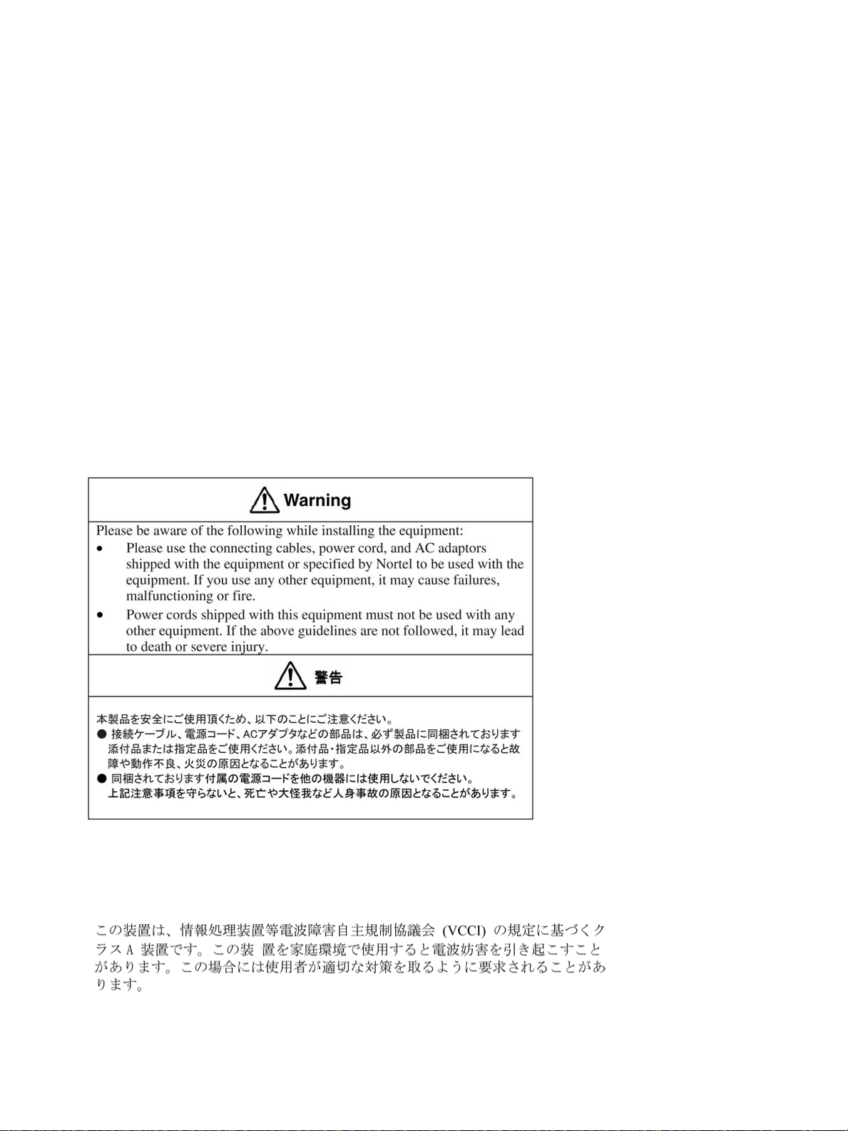
Information for Japan
Japan Denan statement
The following applies to server models 703t, 1002rp, 1005r and 600r:
Japan VCCI statement
The following applies to server models 703t, 201i, 1002rp, 1005r and 600r:
This is a Class A product based on the standard of the Voluntary Control Council for Interference by Information
Technology Equipment (VCCI). If this equipment is used in a domestic environment, radio disturbance may occur, in
which case, the user may be required to take corrective action.
Page 4

Page 5

Publication History
May 2008
CallPilot 5.0, Standard 01.03 of the CallPilot 600r Server Hardware
Installation guide is issued for GA.
May 2007
CallPilot 5.0, Standard 01.02 of the CallPilot 600r Server Hardware
Installation guide is issued for GA.
March 2007
CallPilot 5.0, Standard 01.01 of the CallPilot 600r Server Hardware
Installation guide is issued for GA.
5
Copyright © 2007-2008, Nortel Networks
.
600r Server Hardware Installation
Nortel CallPilot
NN44200-307 01.03 Standard
5.0 14 May 2008
Page 6

6 Publication History
Copyright © 2007-2008, Nortel Networks
.
600r Server Hardware Installation
Nortel CallPilot
NN44200-307 01.03 Standard
5.0 14 May 2008
Page 7

Contents
Chapter 1 How to get help 9
Chapter 2 600r server description 11
Conventions for Warnings 11
Server features 12
PCI riser assembly 16
Network connectivity 16
Supported peripheral devices 19
Reference documents 20
Chapter 3 Preparing for installation 21
Installation overview 21
Unpacking the 600r server 23
Inspecting the interior of server 24
Chapter 4 Installing the server and peripheral devices 27
Installing the server 27
Connecting peripherals to the server 28
Connecting the server to the ELAN subnet 32
Connecting the server to the Nortel server subnet (optional) 33
Installing the Nortel software feature dongle 34
7
Chapter 5 Connecting the server to power 39
Safety precautions 39
Locating the power supply modules 39
Connecting the server to power 40
Chapter 6 EMC emission level protection for the 600r server 45
Index 47
Copyright © 2007-2008, Nortel Networks
.
600r Server Hardware Installation
Nortel CallPilot
NN44200-307 01.03 Standard
5.0 14 May 2008
Page 8

8 Contents
Copyright © 2007-2008, Nortel Networks
.
600r Server Hardware Installation
Nortel CallPilot
NN44200-307 01.03 Standard
5.0 14 May 2008
Page 9

Chapter 1
How to get help
This section explains how to get help for Nortel products and services.
Getting help from the Nortel Web site
The best way to get technical support for Nortel products is from the Nortel
Technical Support Web site:
w
ww.nortel.com/support
This site provides quick access to software, documentation, bulletins, and
tools to address issues with Nortel products. More specifically, the site
enables you to:
• download software, documentation, and product bulletins
•
search the Technical Support Web site and the Nortel Knowledge Base
for answers to technical issues
9
•
sign up for automatic notification of new software and documentation
for Nortel equipment
•
open and manage technical support cases
Getting help over the phone from a Nortel Solutions Center
If you do not find the information you require on the Nortel Technical Support
Web site, and have a Nortel support contract, you can also get help over the
phone from a Nortel Solutions Center.
In North America, call 1-800-4NORTEL (1-800-466-7835).
Outside North America, go to the following Web site to obtain the phone
number for your region:
w
ww.nortel.com/callus
600r Server Hardware Installation
NN44200-307 01.03 Standard
Copyright © 2007-2008, Nortel Networks
.
Nortel CallPilot
5.0 14 May 2008
Page 10

10 Chapter 1 How to get help
Getting help from a specialist by using an Express Routing Code
To access some NortelTechnical Solutions Centers, you can use an Express
Routing Code (ERC) to quickly route your call to a specialist in your Nortel
product or service. To locate the ERC for your product or service, go to:
w
ww.nortel.com/erc
Getting help through a Nortel distributor or reseller
If you purchased a service contract for your Nortel product from a distributor
or authorized reseller, contact the technical support staff for that distributor
or reseller.
Copyright © 2007-2008, Nortel Networks
.
600r Server Hardware Installation
Nortel CallPilot
NN44200-307 01.03 Standard
5.0 14 May 2008
Page 11
Chapter 2
600r server description
In this chapter
"Conventions for Warnings" (page 11)
"Server features" (page 12)
"PCI riser assembly" (page 16)
"Network connectivity" (page 16)
"Supported peripheral devices" (page 19)
"Reference documents" (page 20)
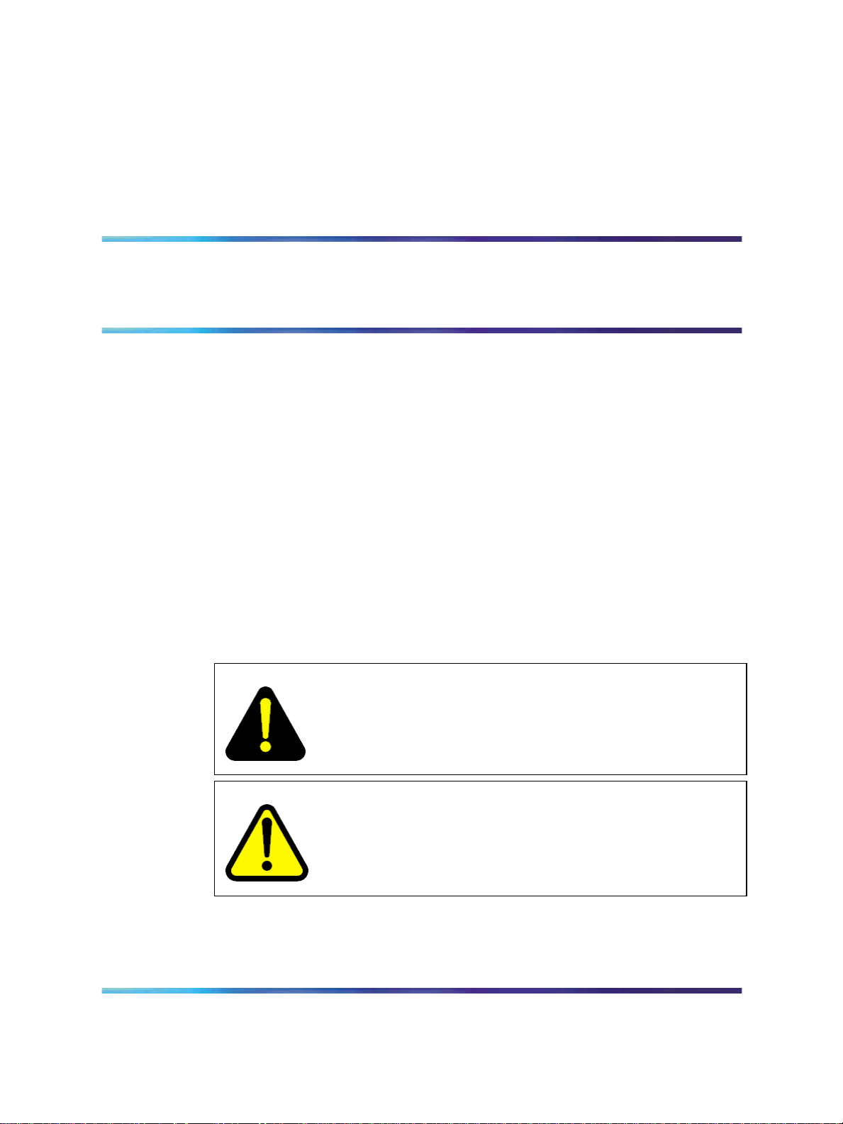
Conventions for Warnings
You can encounter the following types of warnings in this guide. Do not
ignore them.
11
Copyright © 2007-2008, Nortel Networks
.
DANGER
Risk of electric shock
Warns you of an immediate electrical hazard, which, if not avoided,
results in shock, serious injury, or death.
WARNING
Warns you of a situation in which you can be injured if instructions
are not followed exactly as stated.
Nortel CallPilot
600r Server Hardware Installation
NN44200-307 01.03 Standard
5.0 14 May 2008
Page 12

12 Chapter 2 600r server description
CAUTION
Alerts you to situations where data can be lost or damaged,
equipment can be damaged, actions can result in service
interruption, and productive time can be lost.
Provides information that is essential to the completion of a task.
Server features
This section provides a general overview of the 600r server.
The 600r CallPilot server is a long-life industrial computer server in a
standard rack-mount 1U form factor. The 600r utilizes current Intel P4
hyper-threading technology and proven, reliable SCSI hard-drive technology.
Before you install your 600r server, Nortel recommends that you read this
guide completely through. Ensure that CallPilot has the latest antivirus
software. Do not install third-party antivirus software unless approved by
Nortel. For information about the antivirus software packages that are
approved by Nortel for CallPilot, see
: CallPilot Support for Anti-Virus Applications. Also, ensure your CallPilot
application resides behind your network firewall.
ATTENTION
Product Bulletin P-2007-0101-Global
If you have any questions about installing your 600r, contact a Nortel
representative.
Ensure a single-point ground reference is available for all the power outlets
serving the CallPilot server and its peripherals. Before the CallPilot server
installation, a qualified electrician must implement the single-point ground
reference requirement between the power outlets of the CallPilot server
and the power outlets of the switch.
Server dimensions
Height 1.75 inches (44.4 mm)
Width 17.5 inches (444.3 mm)
Depth (distance from front to back) 20 inches (507.8 mm)
Copyright © 2007-2008, Nortel Networks
.
600r Server Hardware Installation
Nortel CallPilot
NN44200-307 01.03 Standard
5.0 14 May 2008
Page 13

Clearance
Server features 13
•
front: 2 inches (50.8 mm)
• rear: 3.6 inches (92 mm)
•
side: 1 inch (25 mm)
Weight of fully loaded system with:
•
SCSI hard drive
•
MPB96 board
•
DVD/CD/CDRW drive
Environmental specifications
Environmental condition
Operating temperature
Non-operating (storage) temperature
Non-operating humidity
Altitude <6000 ft. (1829 m)
approximately 10 kg (23 lbs)
Specification
C to +35C (41Fto95
+5
Maximum rate of change must not
exceed 10
-40
95% @ 23-40
C (50F) per hour.
C to +70C (-40F to +158F)
C
F)
Electrostatic discharge <= 15 kV
Acoustic noise < 55 dBA
Operating shock No errors with a half sine wave shock
Handling drop 2g 11 mS
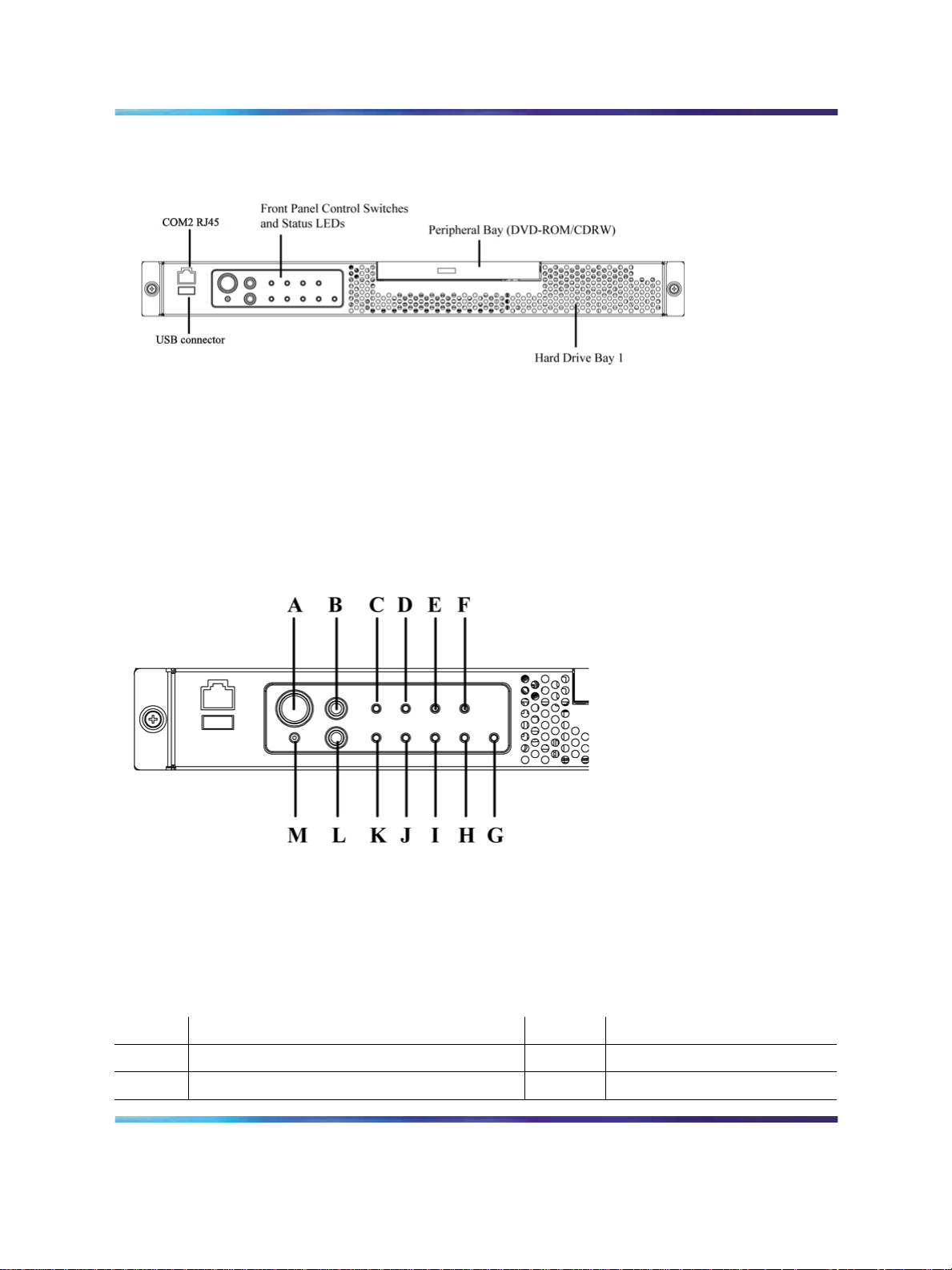
Front panel features
The following diagram shows the front view of the server chassis with the
bezel cover in place. When the bezel cover is removed, Drive Bay 1 is
accessible.
Copyright © 2007-2008, Nortel Networks
.
of 2G (with 1 millisecond duration)
18" free-fall when packaged
Nortel CallPilot
600r Server Hardware Installation
NN44200-307 01.03 Standard
5.0 14 May 2008
Page 14
14 Chapter 2 600r server description
Figure 1 Front panel
The following diagram shows the front panel controls and status LEDs.
For more information about the front panel controls and status LEDs, see
CallPilot 600r Server Maintenance and Diagnostics (NN44200-703.)
Figure 2 Front panel control switches and status LEDs
Note: The faults described in the following table are hardware faults and
are independent of CallPilot application faults.
Table 1 Front panel
Label Description Label Description
A Power button M NMI button (not used)
B Reset button L ID button
600r Server Hardware Installation
NN44200-307 01.03 Standard
Copyright © 2007-2008, Nortel Networks
.
Nortel CallPilot
5.0 14 May 2008
Page 15
Server features 15
Label Description Label Description
C Critical fault LED K System ID LED (white)
D Major fault LED J NIC activity LED (green)
E Minor fault LED I Main power LED (green)
F Power LED H not used
G Disk 0 Activity/Fault LED (green/amber)
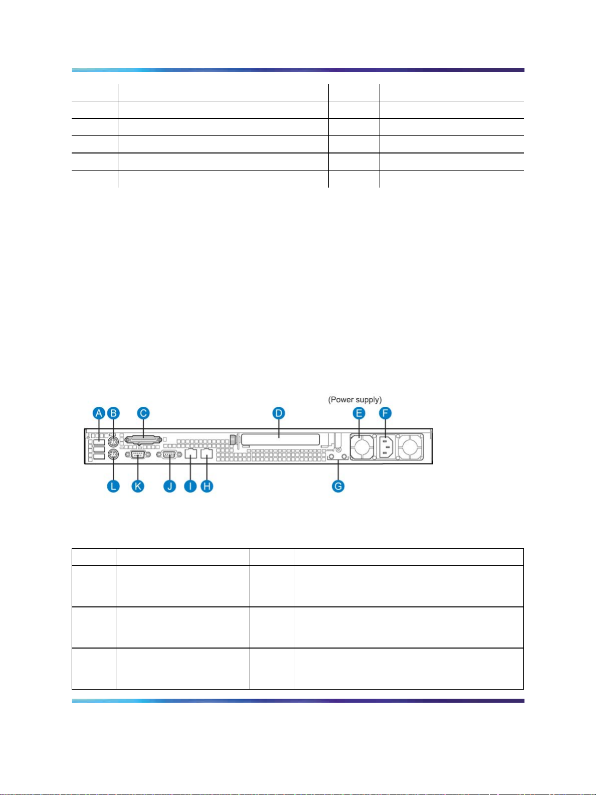
Rear panel controls and features
The following diagram shows the back panel controls and features. On the
right is the AC power supply bank. The PCI card bracket is in the middle
of the back panel, while the connectors and ports are along the bottom
and the left side.
Note: Nortel provides only AC power supply. The server works with a
DC-to-AC converter, however, you must ensure converter meets AC
requirements as specified on label of power supply cover. To access the
power supply cover, remove server cover. For more information about
the server cover, see "To remove the server cover" (page 24).
Figure 3 Rear panel
Table 2 Rear panel
Label Description Label Description
A USB 0, USB 1, USB 2
(labelled 0, 1, 2 on the
server)
B PS/2 Mouse H RJ45 NIC 2 Embedded Local Area Network
G Ground studs (used with system with DC input
power supply)
(ELAN) connector for the ELAN subnet (engraved
2 on server)
C SCSI port I RJ45 NIC 1 Customer Local Area Network
(CLAN) connector for Nortel server subnet
(engraved 1 on server)
600r Server Hardware Installation
NN44200-307 01.03 Standard
Copyright © 2007-2008, Nortel Networks
.
Nortel CallPilot
5.0 14 May 2008
Page 16
16 Chapter 2 600r server description
Label Description Label Description
D PCI card bracket
(full-height) for MPB96
E Power supply K COM1 DB-9 serial port
F AC power input L PS/2 Keyboard connector
J Video connector
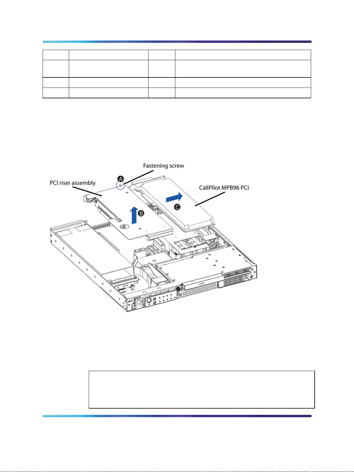
PCI riser assembly
The PCI riser assembly holds the MPB96 voice-processing card. The
following diagram shows the PCI riser assembly above the server.
Figure 4 PCI riser assembly
Network connectivity
This section describes how the 600r server can be integrated into
your network. The 600r can connect to legacy Meridian 1 (M1) and
Communication Server 1000 (CS 1000) systems.
To secure the CallPilot server from unauthorized access, ensure that the CallPilot
network resides behind your network firewall.
Copyright © 2007-2008, Nortel Networks
.
ATTENTION
Nortel CallPilot
600r Server Hardware Installation
NN44200-307 01.03 Standard
5.0 14 May 2008
Page 17

Sample network setup: Meridian 1
The Meridian 1 switch can be one of the following:
•
Option 11C or Option 11C Mini using fiber connections
•
Option 51C
•
Option 61C
•
Options 81 and 81C
The following diagram shows a CallPilot 600r server network setup with
a Meridian 1 switch.
Figure 5 Sample network setup with Meridian 1
Network connectivity 17
Sample network setup: Communication Server 1000
The following diagram shows a CallPilot 600r server network setup with a
CS 1000 system:
Figure 6 Sample network setup with Communication Server 1000
Copyright © 2007-2008, Nortel Networks
.
600r Server Hardware Installation
Nortel CallPilot
NN44200-307 01.03 Standard
5.0 14 May 2008
Page 18

18 Chapter 2 600r server description
In the previous diagram, the telephony LAN (TLAN) subnet provides
IP connectivity between the CS 1000 system and the IP Phones.
The connection between the Call Server and Media Gateway can be
point-to-point, or it can be through the LAN, if the system is installed in
a distributed data network.
For information about the CS 1000 system and IP Phone bandwidth and
network requirements, see the planning and installation documentation
for the CS 1000 (NN430xx).
Switch connectivity
For more details about how the connection between the 600r server and
the switch is established, refer to the switch and server setup document
for your switch.
•
Communication Server 1000 and CallPilot Server Configuration
(NN44200-312)
•
Meridian 1 and CallPilot Server Configuration (NN44200-302)
LAN connectivity
The 600r server contains two Ethernet controllers on the motherboard that
provide the following:
•
10/100Base-T Ethernet network connectivity to the ELAN subnet
ELAN subnet is a network connection from the switch to the CallPilot
server. The ELAN subnet is an Ethernet LAN that enables signaling
and administration access to applications related to the Meridian 1
switch or CS 1000 system. The ELAN subnet is an isolated 10BaseT
subnet required for management traffic and intra-system signaling traffic
between the system call server and any devices requiring call server
processing. A number of configurations are available, depending on
whether the switch has an address on the Nortel server subnet.
For information about the ELAN subnet’s purpose and requirements,
see the Planning and Engineering Guide (NN44200-200).
•
10/100/1000Base-T Ethernet connectivity to the Nortel server subnet
Nortel server subnet is a network set up by a customer for its data
network. The Nortel server subnet is an optional connection that
provides data connectivity among desktop and Web messaging clients,
administrative PCs, and the CallPilot server. Typically, a Nortel server
subnet already exists before CallPilot is installed at a customer site.
Nortel recommends that the customer separate the Nortel server subnet
from the rest of the enterprise IP network by a Layer 3 switch. The Nortel
server subnet connects to the CLAN port on the 600r CallPilot server.
Copyright © 2007-2008, Nortel Networks
.
600r Server Hardware Installation
Nortel CallPilot
NN44200-307 01.03 Standard
5.0 14 May 2008
Page 19

For information about how to identify the location of the network interface
connectors, see "Rear panel controls and features" (page 15).
Network requirements
Appropriate networking equipment must be available for the ELAN subnet
and the optional Nortel server subnet, if it is used.
The ELAN subnet (and the optional Nortel server subnet, if used) must
be properly configured for correct CallPilot operation. To ensure correct
configuration, Nortel recommends that you consult a network specialist.
Remote access connectivity
Use the USB connection on the rear of the 600r server to connect to an
external dial-up modem. With the modem, administrators and technical
support personnel can administer the 600r server from a remote location.
You can also access the 600r server from a remote location directly over the
network, without the use of a modem.
Supported peripheral devices
This section identifies external devices that are supported by the 600r
server.
Supported peripheral devices 19
Table 3 Supported peripheral devices
Device Description
Modem Use a 56 Kb/s external modem to provide remote access to the 600r server.
The modem connects to a USB connector (USB 2, the top connector) on
the rear of the server.
Ethernet switch or
hub
Monitor, keyboard,
and mouse
External tape drive Tandberg SLR75 (optional)
Nortel software
feature dongle
A 10Base-T compliant Ethernet switch or hub provides the ELAN connection
between the 600r server and the Meridian 1 switch or CS 1000 system. The
customer can supply a Ethernet switch or hub from third-party vendors or from
Nortel. Because the Ethernet switch or hub is an external device, the Ethernet
switch or hub requires an AC power source.
•
Monitor: (customer supplied). Because the monitor is an external device,
it requires its own AC power source.
•
Keyboard: (customer supplied)
• Mouse: (customer supplied)
The software feature dongle or key is a security device that stores the unique
serial number of the server. The dongle plugs into a USB connector (USB 0,
the bottom connector) on the rear panel.
Copyright © 2007-2008, Nortel Networks
.
600r Server Hardware Installation
Nortel CallPilot
NN44200-307 01.03 Standard
5.0 14 May 2008
Page 20

20 Chapter 2 600r server description
Reference documents
For a list of all CallPilot documents, see the following CallPilot Customer
Documentation Map.
Copyright © 2007-2008, Nortel Networks
.
600r Server Hardware Installation
Nortel CallPilot
NN44200-307 01.03 Standard
5.0 14 May 2008
Page 21

Chapter 3
Preparing for installation
In this Chapter
"Installation overview" (page 21)
"Unpacking the 600r server" (page 23)
"Inspecting the interior of server" (page 24)
Installation overview
Introduction
This section provides an overview of the steps required to install the 600r
server and peripheral devices. For detailed instructions, see Chapter 4
"Installing the server and peripheral devices" (page 27)
21
When you are finished, continue with the switch and server setup as
described in the documentation for your switch:
•
Communication Server 1000 and CallPilot Server Configuration
(NN44200-312)
•
Meridian 1 and CallPilot Server Configuration (NN44200-302)
Installation checklist
Step
1
Copyright © 2007-2008, Nortel Networks
.
Description
Review the "Installing the CallPilot server" section in the
Installation and Configuration Task List (NN44200-306),
and complete stage 1 of the Installation checklist.
Check
__
Nortel CallPilot
600r Server Hardware Installation
NN44200-307 01.03 Standard
5.0 14 May 2008
Page 22

22 Chapter 3 Preparing for installation
Step
2
3
4
5
6
Description
Unpack the server and ensure you have all the items you
need (see "Unpacking the 600r server" (page 23)).
Complete the following checklists that are provided in the
Installation and Configuration Task List (NN44200-306):
• CallPilot software media and documentation checklist
•
CallPilot server hardware checklist
Remove the top cover and inspect the interior (see
"Inspecting the interior of server" (page 24)).
Replace the top cover.
Place the 600r server in the chosen location and connect
the SCSI terminator (see "Installing the server" (page 27)).
Connect the 600r server and devices as follows:
•
Connect the monitor, keyboard, and mouse (see "To
connect the mouse, keyboard, and monitor to the
server" (page 29)).
•
Connect the modem (see "To connect the modem to
the server" (page 30)).
•
Connect the 600r server to the ELAN Ethernet switch
or hub (see "To connect the server to the ELAN subnet
(Meridian 1 or CS 1000 only)" (page 32)).
Check
__
__
__
__
__
__
__
__
Note: If you are connecting the optional Nortel server
subnet, do not connect until you ensure that CallPilot has
the latest antivirus software. Do not install third-party
antivirus software unless approved by Nortel. For
information about the antivirus software packages that
are approved by Nortel for CallPilot, see Product Bulletin
P-2007-0101-Global : CallPilot Support for Anti-Virus
Applications. Also, ensure your CallPilot application
resides behind your network firewall.
•
Connect the 600r server to the CLAN Ethernet switch
__
or hub (optional); (see "Connecting the server to the
Nortel server subnet (optional)" (page 33)).
•
Install the software feature dongle (see "Installing the
__
Nortel software feature dongle" (page 34)).
•
Connect the power cords for all peripheral devices, and
__
then power them up (see "Connecting the server to
power" (page 40) for power requirements).
7
Start the 600r server (see "What is next?" (page 43)).
__
Copyright © 2007-2008, Nortel Networks
.
600r Server Hardware Installation
Nortel CallPilot
NN44200-307 01.03 Standard
5.0 14 May 2008
Page 23

Unpacking the 600r server
Introduction
Follow this procedure to unpack the server and peripherals.
WARNING
Risk of personal injury
The 600r CallPilot server weighs approximately 10 kg (23 lbs) as
shipped from manufacturing. If necessary, and to prevent personal
injury,ask someone to help you unpack and position the server.
To unpack the equipment
As you unpack each item, check it off against the packing list, as well as against
the following checklists provided in the
(NN44200-306):
• CallPilot software media and documentation checklist
•
CallPilot server hardware checklist
Unpacking the 600r server 23
ATTENTION
Installation and Configuration Task List
Step Action
1 Carefully open the cardboard carton containing the server.
2
3
4
5
What is next?
Remove the top cover to inspect the interior of the server. For information
about how to inspect the interior of the server, see "Inspecting the interior
of server" (page 24).
Remove the server from the carton and place on a secure surface.
Carefully open the cartons containing the monitor, keyboard, mouse,
modem, and ELAN Ethernet switch or hub (if supplied), and set the
peripherals aside.
Put all manuals, DVD/CD/CDRWs, operating system disks, and any
disks for peripherals in a safe place.
Save all packing materials and cartons in case you must return any
equipment to the carrier.
—End—
Copyright © 2007-2008, Nortel Networks
.
600r Server Hardware Installation
Nortel CallPilot
NN44200-307 01.03 Standard
5.0 14 May 2008
Page 24

24 Chapter 3 Preparing for installation
Inspecting the interior of server
Introduction
To inspect the interior of your 600r server, you must remove the servercover.
Note: If the server is powered down, proceed with the next step. If
the server if powered up, see the chapter, "Starting up and shutting
down the CallPilot server", in Installation and Configuration Task List
(NN44200-306) for proper shutdown procedures before you remove
the server cover.
To remove the server cover
Step Action
1
2
Attach the ESD strap to your wrist.
While holding in the blue button at the top of the chassis, slide the
top cover back until it stops.
3
4
5
6
Lift the cover straight up to remove it from the platform.
Ensure the CallPilot PCI riser card is secure.
Inspect the interior for any cables that are not seated properly.
Take note of any physical signs of damage. For example, check for
loose piece parts and screws in the corners of the chassis.
7
If you notice damage to any of the parts in your server, contact your
Nortel representative immediately.
—End—
To replace the server cover
When you finish inspecting the interior of your server, replace the server
cover.
Step Action
1
Attach the ESD strap to your wrist and attach the other end to a
known grounded connection.
2
Place the cover on the server and align the cover with the chassis
tab guides.
3
Copyright © 2007-2008, Nortel Networks
.
Slide the top cover back until it stops.
—End—
Nortel CallPilot
600r Server Hardware Installation
NN44200-307 01.03 Standard
5.0 14 May 2008
Page 25

Inspecting the interior of server 25
What is next?
Continue with the hardware installation, Chapter 4 "Installing the server and
peripheral devices" (page 27). Or, for more information, see "Installation
overview" (page 21).
Copyright © 2007-2008, Nortel Networks
.
600r Server Hardware Installation
Nortel CallPilot
NN44200-307 01.03 Standard
5.0 14 May 2008
Page 26

26 Chapter 3 Preparing for installation
Copyright © 2007-2008, Nortel Networks
.
600r Server Hardware Installation
Nortel CallPilot
NN44200-307 01.03 Standard
5.0 14 May 2008
Page 27

Chapter 4
Installing the server and peripheral
devices
In this chapter
"Installing the server" (page 27)
"Connecting peripherals to the server" (page 28)
"Connecting the server to the ELAN subnet" (page 32)
"Connecting the server to the Nortel server subnet (optional)" (page 33)
"Installing the Nortel software feature dongle" (page 34)
27
Installing the server
Before you install the 600r server, ensure that the chosen location meets
the requirements identified in the Site inspection checklist provided in the
Installation and Configuration Task List (NN44200-306).
Note: The 600r server is supplied with industry standard 48.3 cm (19
in.) rack rails that can accommodate racks with a maximum depth of 61
cm (24 in.) between the mounting posts. Check the rack you are using
and ensure that the Nortel supplied server rack rails are suitable for your
specific installation requirements. For depths greater than 61 cm (24
in.), Nortel recommends that you purchase a third-party rack shelf that
can safely hold up to 23 kg (50 lb.)
Copyright © 2007-2008, Nortel Networks
.
600r Server Hardware Installation
Nortel CallPilot
NN44200-307 01.03 Standard
5.0 14 May 2008
Page 28

28 Chapter 4 Installing the server and peripheral devices
To install the server
Step Action
1
Place the 600r server in its chosen location. If you are installing
the server in a rack cabinet, follow the instructions provided with
the slide rails.
Note: The DS30X cable that connects the NTRH40AA MPB96
board to the MGate cards is 20 m (60 feet) long. With this cable,
you can place the server in a different room from the Meridian
1 switch or CS 1000 system.
The DS30 cables that connect the NTRH40CA MPB96 board to
the NTRB18DA MGate cards can be up to 600 m (
1968 feet)
long. With this cable you can place the server in a different
building from the Meridian 1 switch or CS 1000 system.
2
Locate the external SCSI terminator (included loose within the
server shipping carton). Connect the terminator to the rear SCSI
port labeled C in Figure 7 "Rear panel" (page 29). For an illustration
of the SCSI terminator, see the item labeled Server terminator in
Figure 8 "SCSI tape drive with terminator" (page 31).
CAUTION
It is imperative that you install the terminator to ensure reliable
server operation. Failure to do so will result in an inability to load
the operating system.
3
Connect peripheral devices as described in this chapter.
What is next?
Connect peripheral devices as described in this chapter.
Connecting peripherals to the server
Rear panel connectors
The following diagram shows the connectors on the rear panel of the 600r.
600r Server Hardware Installation
NN44200-307 01.03 Standard
Copyright © 2007-2008, Nortel Networks
.
Nortel CallPilot
5.0 14 May 2008
—End—
Page 29

Figure 7 Rear panel
Table 4 Rear panel connectors
Label Description Label Description
Connecting peripherals to the server 29
A USB 0, USB 1, USB 2
(labelled 0, 1, 2 on server)
B PS/2 Mouse H RJ45 NIC 2 ELAN connector (labelled 2 on
C SCSI port I RJ45 NIC 1 CLAN connector (labelled 1 on
D PCIcardbracket(full-height)
for MPB96
E Power supply K COM1 DB-9 serial port
F AC power input L PS/2 Keyboard connector
G Ground studs (used with system with DC input
power supply)
server)
server)
J Video connector
To connect the mouse, keyboard, and monitor to the server
Step Action
1
2
Place the monitor, keyboard, and mouse in the same location as
the server.
Plug the keyboard and mouse into the appropriate PS/2 connectors
on the chassis rear panel. See labels L and B, respectively, on the
diagram.
3
Plug in the monitor connector (see diagram, label J). Tighten the
screws on the connector.
4 Connect the power cord to the monitor and plug the other end into
a wall receptacle or power bar.
5
Copyright © 2007-2008, Nortel Networks
.
Turn on the monitor.
—End—
Nortel CallPilot
600r Server Hardware Installation
NN44200-307 01.03 Standard
5.0 14 May 2008
Page 30

30 Chapter 4 Installing the server and peripheral devices
To connect the modem to the server
You require a modem to support remote dial-up access to the CallPilot
server. With a modem, Nortel technical support can connect to your
CallPilot server for troubleshooting purposes. Nortel connects to your server
only when you request technical assistance.
Windows automatically recognizes your modem after you connect it and
power it on. The power light (PWR LED) does not illuminate until the
Windows device driver successfully loads and recognizes the hardware.
To install the modem, you need the following equipment:
•
USB modem
•
RJ-11 analog phone cord
• USB cable (supplied with the modem)
•
an analog line jack
Serial port modems with RS-232 connections are not supported on the 600r.
Step Action
1
2
3
Connect one end of the USB cable into the modem.
Connect the other end of the USB cable into USB 2 on the rear panel.
Connect one end of the telephone cable to the modem RJ-11 jack
labeled LINE.
4
Connect the other end of the telephone cable to the RJ-11 jack in
the wall.
—End—
To connect the external SCSI tape drive
When you connect an external SCSI tape drive, the device must be
terminated. Your tape drive comes with a terminator. (See Tape drive
terminator in Figure 8 "SCSI tape drive with terminator" (page 31).) The
600r server also comes with a server terminator, a VHDCI (Very High
Density Connection Interface) Ultra320 SCSI terminator. (See Server
terminator in Figure 8 "SCSI tape drive with terminator" (page 31).) In a
previous procedure, you are instructed to connect the server terminator to
the SCSI port. Before you connect an external tape drive to the 600r, you
must remove the server terminator.
Note: If you do not connect a SCSI device to the server, do not remove
the server terminator from the SCSI port.
Copyright © 2007-2008, Nortel Networks
.
600r Server Hardware Installation
Nortel CallPilot
NN44200-307 01.03 Standard
5.0 14 May 2008
Page 31

Step Action
Connecting peripherals to the server 31
WARNING
The terminator is not a hot-plug device. If you replace the
terminator, or if you add an external SCSI peripheral, the server
must be powered off. If you replace the terminator or add a SCSI
peripheral when the system is on, the system can crash.
1
Power off the server and the tape drive.
Note: For the proper shutdown procedure, see the chapter,
"Starting up and shutting down the CallPilot server"in Installation
and Configuration Task List (NN44200-306).
2
Set the SCSI ID push button switch, located on the back of the tape
drive, to 6.
3
Connect the external SCSI tape drive to the SCSI port in the rear
panel, Label C on the rear panel diagram, as shown in Figure 7
"Rear panel" (page 29).
Note: You must remove the server terminator before you
connect the tape drive to the server. Keep the server terminator
in a safe place, as you may need the server terminator when
you want to use the server, and the tape drive is not available to
terminate the SCSI bus.
Figure 8 SCSI tape drive with terminator
Copyright © 2007-2008, Nortel Networks
.
600r Server Hardware Installation
Nortel CallPilot
NN44200-307 01.03 Standard
5.0 14 May 2008
Page 32

32 Chapter 4 Installing the server and peripheral devices
4
5
6
What is next?
Connect the server to the ELAN subnet and Nortel server subnet (if
applicable).
Install the SCSI tape drive terminator to the back of the SCSI tape
drive, as shown in Figure 8, under the label Tape drive terminator.
Note: Nortel does not recommend connecting older SCSI
protocol terminators, as this can affect server performance.
Plug the tape drive into the same single point ground and A/C power
as the rest of the system.
Power on the tape drive.
Note: Your 600r comes with the tape drive drivers preinstalled.
During the loading of Windows, the system automatically detects
the tape drive and loads the driversthat are necessary to operate
the tape drive. When system startup is complete, the tape drive
is ready for use.
—End—
Note: Before you connect to the network, ensure that CallPilot has the
latest antivirus software. Do not install third-party antivirus software
unless approved by Nortel. For information about the antivirus software
packages that are approved by Nortel for CallPilot, see Product Bulletin
P-2007-0101-Global : CallPilot Support for Anti-Virus Applications. Also,
ensure your CallPilot application resides behind your network firewall.
Connecting the server to the ELAN subnet
Connect the CallPilot server to the Meridian 1 switch or CS 1000 system
using the ELAN subnet.
ATTENTION
For important considerations about using the ELAN subnet in your network, see
the Planning and Engineering Guide (NN44200-200).
To connect the server to the ELAN subnet (Meridian 1 or CS 1000 only)
Step Action
1
On the back of the server, locate the ELAN Ethernet connector.
Copyright © 2007-2008, Nortel Networks
.
600r Server Hardware Installation
Nortel CallPilot
NN44200-307 01.03 Standard
5.0 14 May 2008
Page 33

Connecting the server to the Nortel server subnet (optional) 33
Note: The ELAN connector is labeled 2 on the rear panel of the
server. For the connector location, refer to diagram Figure 12
"Rear panel" (page 40), label H on the diagram.
2
What is next?
If the server Then
is connected to a Nortel server
subnet
is not connected to a Nortel server
subnet
Connect an RJ-45 network cable from the ELAN Ethernet switch or
hub to the server’s ELAN connector.
Note: The ELAN Ethernet switch or hub is optional if you
use a crossover network cable to make a direct point-to-point
connection from the server to the switch. However, if you choose
to establish a direct point-to-point ELAN connection, no other
device can connect to the ELAN subnet. For specific connection
details, see the CS 1000 network documentation.
—End—
continue with "Connecting the server to the
Nortel server subnet (optional)" (page 33).
continue with installing the software feature
dongle. See "Installing the Nortel software
feature dongle" (page 34).
Connecting the server to the Nortel server subnet (optional)
This section provides instructions to connect the server to the Nortel server
subnet.
Note: The CLAN connection is optional. However, connection to
a Nortel server subnet is required for support of desktop and Web
messaging users, or administration by means of a Web-enabled PC.
Ensure that CallPilot has the latest antivirus software. Do not install
third-party antivirus software unless approved by Nortel. For information
about the antivirus software packages that are approved by Nortel for
CallPilot, see Product Bulletin P-2007-0101-Global : CallPilot Support
for Anti-Virus Applications.
Media Access Control address
The Media Access Control (MAC) address is a unique number assigned to
network cards and controllers. You can find the MAC address bar code label
located on top of the chassis, directly above the front main push-button
600r Server Hardware Installation
NN44200-307 01.03 Standard
Copyright © 2007-2008, Nortel Networks
.
Nortel CallPilot
5.0 14 May 2008
Page 34

34 Chapter 4 Installing the server and peripheral devices
power switch. Two MAC addresses are shown on the label. The CLAN
MAC address is the top MAC address, labeled MAC1, while the ELAN MAC
address is labelled MAC2.
To connect the server to the Nortel server subnet
Step Action
1
2
What is next?
Continue with "Installing the Nortel software feature dongle" (page 34).
On the back of the server, locate the CLAN connector.
Note: The CLAN connector is labeled 1 on the rear panel of the
600r. For the connector location, see the diagram on Figure 7
"Rear panel" (page 29), Label I.
Connect an RJ-45 network cable from the CLAN Ethernet switch
or hub to the CLAN connector.
Note: When connecting the optional Nortel server subnet, do
not connect to the network until you ensure that CallPilot has
the latest antivirus software. Do not install third-party antivirus
software unless approved by Nortel. For information about the
antivirus software packages that are approved by Nortel for
CallPilot, see
Product Bulletin P-2007-0101-Global : CallPilot
Support for Anti-Virus Applications. Also, ensure your CallPilot
application resides behind your network firewall.
—End—
Installing the Nortel software feature dongle
The software feature key is a security device that stores the unique serial
number of the server. The feature key is embedded in the Nortel software
feature dongle that plugs in to a USB port on the rear panel.
The following diagram shows the dongle plugged in to the back panel of
the server:
600r Server Hardware Installation
NN44200-307 01.03 Standard
Copyright © 2007-2008, Nortel Networks
.
Nortel CallPilot
5.0 14 May 2008
Page 35

Figure 9 Dongle plugged in to server
Installing the Nortel software feature dongle 35
To install the software feature dongle
Step Action
1
2 If the software feature key is not preinstalled in the dongle, insert the
Copyright © 2007-2008, Nortel Networks
.
On the rear panel, ensure that there is nothing plugged in to USB 0,
the bottom USB connector.
key in to the software feature slot in the dongle.
600r Server Hardware Installation
Nortel CallPilot
NN44200-307 01.03 Standard
5.0 14 May 2008
Page 36

36 Chapter 4 Installing the server and peripheral devices
Figure 10 Dongle without feature key
a. Toopen the dongle to insert the software feature key, gently push
back the clip on side of the dongle using a very small screwdriver
and pull back on the access door.
b. Insert the software feature key with the data contact facing down
and away from the embossed i. (For more information about
installing the software feature key, see Figure 11 "Installing the
software feature key" (page 36).
Figure 11 Installing the software feature key
3
Copyright © 2007-2008, Nortel Networks
.
Remove the front protection cover from the dongle.
600r Server Hardware Installation
Nortel CallPilot
NN44200-307 01.03 Standard
5.0 14 May 2008
Page 37

Installing the Nortel software feature dongle 37
4
What is next?
Continue with Chapter 5 "Connecting the server to power" (page 39).
Plug the dongle in to USB port 0, the bottom USB connector, on the
rear panel of the server.
Note: Due to system driver allocations, the dongle must be
installed in USB port 0.
—End—
Copyright © 2007-2008, Nortel Networks
.
600r Server Hardware Installation
Nortel CallPilot
NN44200-307 01.03 Standard
5.0 14 May 2008
Page 38

38 Chapter 4 Installing the server and peripheral devices
Copyright © 2007-2008, Nortel Networks
.
600r Server Hardware Installation
Nortel CallPilot
NN44200-307 01.03 Standard
5.0 14 May 2008
Page 39

Chapter 5
Connecting the server to power
In this chapter
"Safety precautions" (page 39)
"Locating the power supply modules" (page 39)
"Connecting the server to power" (page 40)
Safety precautions
Equipment handling guidelines
External power equipment, such as an Uninterruptible Power Supply
(UPS), is usually very heavy. This equipment requires special handling
procedures and additional personnel for unloading and installation. Be
aware of weight distribution, and prevent the equipment room floor from
being overly stressed.
39
Safety information
DANGER
Procedures involving electrical connections must be performed
only by qualified personnel. Ensure that you obey all displayed
warning notices on power equipment and connections.
Locating the power supply modules
Introduction
The AC power supply module is shipped installed. The following diagram
shows the location of the power supply module in the back panel (E).
Note: Nortel provides only AC power supply. The server works with a
DC-to-AC converter, however, you must ensure the converter meets
600r Server Hardware Installation
NN44200-307 01.03 Standard
Copyright © 2007-2008, Nortel Networks
.
Nortel CallPilot
5.0 14 May 2008
Page 40

40 Chapter 5 Connecting the server to power
AC requirements as specified on the label of the power supply cover.
To access the power supply cover, remove the server cover. For more
information about how to remove the server cover, see "To remove the
server cover" (page 24).
Figure 12 Rear panel
About the power supply module
After the server is powered up, the power supply module LED indicates its
status.
A green LED on the power supply module indicates that the module is
working properly. If the LED is not lit or red, the module has failed to power
up. A problem with a power supply module is also indicated if the PWR or
MJR LED light on the front of the server is red.
Rack power and grounding
To ensure a complete power and grounding installation:
•
In rack-mount server installations, ensure the CallPilot server chassis
and equipment racks are isolated from other foreign sources of ground.
Acceptable isolation methods include: isolation pads, grommeted
washers, chassis side-rail strips, and non-conducting washers (not
included.)
•
In rack-mount server installations where other equipment is also
installed in the same rack, ensure that all equipment derives ground
from the same service panel as CallPilot and the switch.
Connecting the server to power
Before you begin
Ensure that proper power and grounding are available for all the power
outlets serving the CallPilot server and its associated peripherals. Power
for these devices must be wired and fused independently of all other
receptacles and referenced to the same ground as the PBX system.
Copyright © 2007-2008, Nortel Networks
.
600r Server Hardware Installation
Nortel CallPilot
NN44200-307 01.03 Standard
5.0 14 May 2008
Page 41

Connecting the server to power 41
A qualified electrician must implement the single-point ground reference as
required among the power outlets of the CallPilot server, its associated
peripherals, and the power outlets of the switch.
Provide a sufficient number of properly grounded power outlets or power
bars for all equipment.
The single-point ground (SPG) required by the system can be an isolated
ground (IG) bus or AC equipment ground (ACEG) bus in the service
panel or transformer. The system must be connected to safety ground or
protective earth in accordance with NEC requirements. For international
use, the system must be connected to safety ground or protective earth in
accordance with Paragraph 2.5 of EN60950/IEC950.
Note: For a complete description of approved ground sources and
methods, seeCommunication Server 1000M and Meridian 1: Large
System Planning and Engineering (NN43021-220). Insulated ground
wire must be used for system grounding.
Before you connect the server to the power source, review the following
diagram and the warning that follows to ensure that all peripheral hardware
devices are in place.
Copyright © 2007-2008, Nortel Networks
.
600r Server Hardware Installation
Nortel CallPilot
NN44200-307 01.03 Standard
5.0 14 May 2008
Page 42

42 Chapter 5 Connecting the server to power
Figure 13 Example setup of 600r with peripherals
To connect the 600r server to power
Copyright © 2007-2008, Nortel Networks
.
WARNING
Risk of personal injury and risk of hardware failure
You must connect the power outlets that are used by the CallPilot
server and its peripheral devices to the same single-point ground
reference as the one used by the switch with MGate cards
connected to the CallPilot server.
If this requirement is not met, power transients can cause
personal injury, hardware failure, or both. For more information
about single-point grounding requirements, seeInstallation and
Configuration Task List (NN44200-306).
Nortel CallPilot
600r Server Hardware Installation
NN44200-307 01.03 Standard
5.0 14 May 2008
Page 43

Connecting the server to power 43
Note: When the 600r server is plugged into an AC outlet with power,
the server automatically powers on. If there is a power outage and the
600r server loses power, the server automatically powers up after power
is restored.
Step Action
1
2
Plug the server AC power cord into the server rear panel.
Plug the other end into an approved wall receptacle or power bar.
—End—
What is next?
Proceed to the Installation and Configuration Task List (NN44200-306) for
details.
Copyright © 2007-2008, Nortel Networks
.
600r Server Hardware Installation
Nortel CallPilot
NN44200-307 01.03 Standard
5.0 14 May 2008
Page 44

44 Chapter 5 Connecting the server to power
Copyright © 2007-2008, Nortel Networks
.
600r Server Hardware Installation
Nortel CallPilot
NN44200-307 01.03 Standard
5.0 14 May 2008
Page 45

Chapter 6
EMC emission level protection for the
600r server
To lower the EMC emission level, ferrite cores are installed with one loop on
the following external cables:
• Ferrite Core (TDK and part number ZCAT3035-1330) for the triple
DS30X I/O cable (Nortel and part number NTRH2014E6), at each end
of the cable.
CAUTION
The ferrite cores are preinstalled on the provided cable. It is not
your responsibility to attach these ferrite cores to these cables.
However, you must ensure that these ferrites are in place to keep
the EMC emission levels low.
45
Copyright © 2007-2008, Nortel Networks
.
600r Server Hardware Installation
Nortel CallPilot
NN44200-307 01.03 Standard
5.0 14 May 2008
Page 46

46 Chapter 6 EMC emission level protection for the 600r server
Figure 14 Ferrite cores secured to an external cable
Ferrites
Connectors for the
MGate cards
The ferrite cores are secured to the appropriate cable with plastic enclosure
clips. Tie wraps are added to the cable loop.
Copyright © 2007-2008, Nortel Networks
.
Connector for the
MPB96 board
G101786
Nortel CallPilot
600r Server Hardware Installation
NN44200-307 01.03 Standard
5.0 14 May 2008
Page 47

Index
47
Symbols/Numerics
600r server
connections
establishing 37
power 37
dimensions 12
ELAN
connection, establishing 32
environmental specifications 13
front panel, description 13
installing 28
Nortel server subnet
connection, establishing 34
peripheral devices, connecting 28
power connection, establishing 42
rear panel, description 28
server cover
replacing 24
unpacking 23
600r server cover
removing 24
replacing 24
A
adapter, software feature key 35
C
checklist, installation 21
COM1 connection, description 19
Communication Server 1000, CallPilot
network setup 17
connectivity
ELAN 18
Nortel server subnet 18
remote access 19
Customer LAN
CLAN 33
D
DC power input 29
devices, peripheral 19
diagrams
CallPilot network connections
Communication Server 1000 17
Meridian 1 17
front panel 13
rear panel 15, 28
server cover
replacing 24
software feature key adapter 35
TLAN subnet (Communication Server
1000) 17
dimensions, 600r server 12
dongle 34
E
ELAN subnet
connecting server to 32
Embedded LAN
ELAN 32
environmentalspecifications,600rserver 13
F
fax modem
required equipment 30
front bezel
Copyright © 2007-2008, Nortel Networks
.
600r Server Hardware Installation
Nortel CallPilot
NN44200-307 01.03 Standard
5.0 14 May 2008
Page 48

48 Index
replacing 24
front panel, description 13
K
keyboard
connecting to the server 29
L
LAN connections, description 18
M
Meridian 1, CallPilot server network
setup 17
modem
connecting to the server 30
required equipment 30
monitor
connecting to the server 29
mouse
connecting to the server 29
N
network
controllers 18
protocols 18
setup, CallPilot
Communication Server 1000 17
Meridian 1 17
Nortel server subnet
connecting server to 34
P
peripheral devices 19
connecting to the server 28
power
connecting server to 42
grounding, requirement 42
protocols, supported network 18
S
serial number 34
server 24
connections
establishing 37
power 37
cover
removing 24
dimensions 12
ELAN
connection, establishing 32
environmental specifications 13
front panel, description 13
installing 28
Nortel server subnet
connection, establishing 34
peripheral devices, connecting 28
power connection establishing 42
rear panel, description 28
replacing 24
serial number 34
unpacking 23
server cover
removing 24
replacing 24, 24
single-point grounding, power
requirement 42
slot locations 15
software feature key 34
software feature key adapter
description 35
installing 35
specifications, environmental 13
T
telephony LAN
TLAN subnet 18
TLAN subnet, diagram 17
top cover
replacing 24
R
rear panel, description 15, 28
remote access connectivity 19
Copyright © 2007-2008, Nortel Networks
.
U
unpacking 23
USB connection 19
Nortel CallPilot
600r Server Hardware Installation
NN44200-307 01.03 Standard
5.0 14 May 2008
Page 49

W
warnings, conventions 11
Index 49
Copyright © 2007-2008, Nortel Networks
.
600r Server Hardware Installation
Nortel CallPilot
NN44200-307 01.03 Standard
5.0 14 May 2008
Page 50

50 Index
Copyright © 2007-2008, Nortel Networks
.
600r Server Hardware Installation
Nortel CallPilot
NN44200-307 01.03 Standard
5.0 14 May 2008
Page 51

Page 52

Nortel CallPilot
600r Server Hardware Installation
Copyright © 2007-2008, Nortel Networks
All Rights Reserved.
Publication: NN44200-307
Document status: Standard
Document version: 01.03
Document date: 14 May 2008
To provide feedback or report a problem in this document, go to w
Sourced in Canada
The information in this document is subject to change without notice. The statements, configurations, technical data, and
recommendations in this document are believed to be accurate and reliable, but are presented without express or implied
warranty. Users must take full responsibility for their applications of any products specified in this document. The information in
this document is proprietary to Nortel Networks.
*Nortel, the Nortel logo, and the Globemark are trademarks of Nortel Networks.
*Microsoft, MS, MS-DOS, Windows, and Windows NT are registered trademarks of Microsoft Corporation.
All other trademarks and registered trademarks are the property of their respective owners.
ww.nortel.com/documentfeedback.
 Loading...