

Page 1

Meridian 1
Option 11C Mini
Planning and Installation Guide
Document Number: 553-3021-209
Document Release: Standard 3.00
Date: April 2000
Year Publish FC C TM
Copyright © 1999–2000 Nortel Networks
All Rights Reserved
Printed in C an ad a
Information is subject to change without notice. Nortel Networks reserves the right to make changes in design
or components as progress in engineering and manufacturing may warrant. This equipment has been tested
and found to comply with the limits for a Class A digital device pursuant to Part 15 of the FCC rules, and the
radio interference regulations of Industry Canada. These limits ar e designed to provide reaso nable pro tection
against harmful interference when the equipment is operated in a commercial environment. This equipment
generates, uses and can radiate radio frequency energy, and if not installed and used in accordance with the
instruction manual, may cause h armful i nterference to radio communications. Oper ation of this equipment in a
residential area is likely to cau s e harmfu l interference i n which case the user will be required to correct the
interference at their own expense.
SL-1 and Meridian 1 are trademarks of Nortel Networks.
Option 11C Mini Planning and Installati on G uide
Page 2

Page 3

4
Page 3 of 332
Revision history
April 2000
Issue 3.00, Standard. This is a global document and is up-issued for X11
Release 25.0x.
September 1999
Issue 2.00, Standard. Updated to include Option 11C Mini Phase II content.
“Appendix A: General information for the United Kingdom” was removed
from this guide. For UK-specific information, refer to the
for the UK (553-3001-110)
Also, “Appendix B: Additional information for installations in Germany”
was removed from this guide. Refer to “Chapter 5 — Regulatory
information” on page 83 for European regulatory informat ion.
.
Meridian 1 Gui de
July 1999
Issue 1.00, Standard.
Option 11C Mini Planning and Installation Guide
Page 4

Page 4 o f 332
553-3021-209 Standard 3.00 April 2000
Page 5

12
Page 5 of 332
Contents
About this guide . . . . . . . . . . . . . . . . . . . . . . . . . . . 13
Who should read this guide . . . . . . . . . . . . . . . . . . . . . . . . . . . . . . . . . 13
How this guide is organized . . . . . . . . . . . . . . . . . . . . . . . . . . . . . . . . . 13
Terminology used in this guide . . . . . . . . . . . . . . . . . . . . . . . . . . . . . . 14
Related documents . . . . . . . . . . . . . . . . . . . . . . . . . . . . . . . . . . . . . . . . 15
Chapter 1 — Introducing the Option 11C Mini . . . 17
Option 11C Mini system description . . . . . . . . . . . . . . . . . . . . . . . . . . 17
Installing software and configuring data . . . . . . . . . . . . . . . . . . . . . 19
Supported applications . . . . . . . . . . . . . . . . . . . . . . . . . . . . . . . . . . 21
System specifications . . . . . . . . . . . . . . . . . . . . . . . . . . . . . . . . . . . 22
Data backup and restore methods . . . . . . . . . . . . . . . . . . . . . . . . . . 24
Repair facilities . . . . . . . . . . . . . . . . . . . . . . . . . . . . . . . . . . . . . . . . . . 25
Asia Pacific, Ca ribbean and Latin Americ a, and North America . . 25
Europe . . . . . . . . . . . . . . . . . . . . . . . . . . . . . . . . . . . . . . . . . . . . . . . 25
Chapter 2 — Identifying the Option 11C
Mini equipment . . . . . . . . . . . . . . . . . . . . . . . . . . . . 27
Main components of the Option 11C Mini . . . . . . . . . . . . . . . . . . . . . 27
NTDK91 Main Chassis
NTDK92 Chassis Expander . . . . . . . . . . . . . . . . . . . . . . . . . . . . . . 27
Power supply . . . . . . . . . . . . . . . . . . . . . . . . . . . . . . . . . . . . . . . . . . 31
Reserve power supply . . . . . . . . . . . . . . . . . . . . . . . . . . . . . . . . . . . 35
Circuit cards . . . . . . . . . . . . . . . . . . . . . . . . . . . . . . . . . . . . . . . . . . . 35
Telephones and Attendant Consoles . . . . . . . . . . . . . . . . . . . . . . . . 36
Cables and wires . . . . . . . . . . . . . . . . . . . . . . . . . . . . . . . . . . . . . . . 37
Option 11C Mini Planning and Installation Guide
Page 6

Page 6 o f 332 Contents
Miscellaneous items for installation . . . . . . . . . . . . . . . . . . . . . . . . 40
Differences bet ween Option 11C Mini and Option 11C . . . . . . . . . . . 41
Chapter 3 — System and site requirements . . . . 45
Environmental requirements . . . . . . . . . . . . . . . . . . . . . . . . . . . . . . . . 45
Earthquake bracing requirements for chassis installed on a
wall in a vertical position . . . . . . . . . . . . . . . . . . . . . . . . . . . . . . . . . . 46
Grounding requirements . . . . . . . . . . . . . . . . . . . . . . . . . . . . . . . . . . . 47
Grounding method . . . . . . . . . . . . . . . . . . . . . . . . . . . . . . . . . . . . . 53
Conduit requirements . . . . . . . . . . . . . . . . . . . . . . . . . . . . . . . . . . . 54
Commercial power requirements . . . . . . . . . . . . . . . . . . . . . . . . . . . . . 55
AC power installation for systems install ed on a wall or table . . . . 55
AC power installation for systems installed in a rack/cabinet . . . . 55
Alternative AC-powered installation . . . . . . . . . . . . . . . . . . . . . . . 58
Power consumption works heets for the Option 11C Mini system . 64
Auxiliary equipment power . . . . . . . . . . . . . . . . . . . . . . . . . . . . . . . . . 66
Modem requirements . . . . . . . . . . . . . . . . . . . . . . . . . . . . . . . . . . . . . . 66
Maintenance and administration terminals . . . . . . . . . . . . . . . . . . . . . 67
On-site access . . . . . . . . . . . . . . . . . . . . . . . . . . . . . . . . . . . . . . . . . 67
Remote access . . . . . . . . . . . . . . . . . . . . . . . . . . . . . . . . . . . . . . . . . 67
Meridian Administration Tools . . . . . . . . . . . . . . . . . . . . . . . . . . . . 68
Cross-connect terminal requirements . . . . . . . . . . . . . . . . . . . . . . . . . 68
Chapter 4 — Creating an equipment
layout plan and a card slot assignment plan . . . . 69
Equipment layout plan . . . . . . . . . . . . . . . . . . . . . . . . . . . . . . . . . . . . . 69
General layout guidelines . . . . . . . . . . . . . . . . . . . . . . . . . . . . . . . . 69
Equipment layout plan for installing the chassis on a wall
horizontally and vertically . . . . . . . . . . . . . . . . . . . . . . . . . . . . . . . 70
Equipment layout plan for install ing the chassis on a table . . . . . . 73
Equipment layout plan for installing the chassis in a rack/cabinet . 75
Card slot assignments . . . . . . . . . . . . . . . . . . . . . . . . . . . . . . . . . . . . . 77
Chapter 5 — Regulatory information . . . . . . . . . . 83
System approval . . . . . . . . . . . . . . . . . . . . . . . . . . . . . . . . . . . . . . . . . . 83
Notice for United States installations . . . . . . . . . . . . . . . . . . . . . . . . . 83
553-3021-209 Standard 3.00 April 2000
Page 7

Contents Page 7 of 332
Importance of Ringer Equivalence Number . . . . . . . . . . . . . . . . . . 83
Hearing aid compatibility . . . . . . . . . . . . . . . . . . . . . . . . . . . . . . . . 84
Notice for Canadian installations . . . . . . . . . . . . . . . . . . . . . . . . . . . . . 84
Notice for international installations . . . . . . . . . . . . . . . . . . . . . . . . . . 85
European compliance information . . . . . . . . . . . . . . . . . . . . . . . . . 86
Canadian and United States Network connections . . . . . . . . . . . . . . . 86
FCC compliance: registered equipment for Di rec t Inward Dial
(DID) calls . . . . . . . . . . . . . . . . . . . . . . . . . . . . . . . . . . . . . . . . . . . . 87
Radio and TV interference . . . . . . . . . . . . . . . . . . . . . . . . . . . . . . . . . . 87
Information for the United States . . . . . . . . . . . . . . . . . . . . . . . . . . 87
Information for Canada . . . . . . . . . . . . . . . . . . . . . . . . . . . . . . . . . . 89
Chapter 6 — Installing the Option 11C Mini . . . . . 91
Tools checklist . . . . . . . . . . . . . . . . . . . . . . . . . . . . . . . . . . . . . . . . . . . 91
Readiness checklist . . . . . . . . . . . . . . . . . . . . . . . . . . . . . . . . . . . . . . . 92
Summary of installation procedures . . . . . . . . . . . . . . . . . . . . . . . . . . . 92
Chapter 7 — Important safety instructions . . . . . . 101
Symbols you must recogni ze . . . . . . . . . . . . . . . . . . . . . . . . . . . . . . . . 101
Safety instru ctions when installi ng telephone equipment . . . . . . . . . . 102
Safety instructions when using telephone equipment . . . . . . . . . . . . . 102
Chapter 8 — Bracing the Option 11C Mini
against earthquakes . . . . . . . . . . . . . . . . . . . . . . . . 105
Method for earthquake bracing . . . . . . . . . . . . . . . . . . . . . . . . . . . . 105
Chapter 9 — Installing the chassis . . . . . . . . . . . . 115
Installing the chassis on a wall in a vertical position . . . . . . . . . . . . . . 116
Items required . . . . . . . . . . . . . . . . . . . . . . . . . . . . . . . . . . . . . . . . . 116
Installi ng the chassis on a wall in a horizontal position . . . . . . . . . . . . 121
Items required . . . . . . . . . . . . . . . . . . . . . . . . . . . . . . . . . . . . . . . . . 121
Installing the chassis on a table . . . . . . . . . . . . . . . . . . . . . . . . . . . . . . 126
Items required . . . . . . . . . . . . . . . . . . . . . . . . . . . . . . . . . . . . . . . . . 126
Installing the chassis in a 19 inch rack/cabinet . . . . . . . . . . . . . . . . . . 129
Items required . . . . . . . . . . . . . . . . . . . . . . . . . . . . . . . . . . . . . . . . . 129
Option 11C Mini Planning and Installation Guide
Page 8

Page 8 o f 332 Contents
Chapter 10 — Connecting the Chassis
Expander to the Main Chassis . . . . . . . . . . . . . . . 135
Chapter 11 – Installing the system ground . . . . . 139
Chassis powered by the same service panel . . . . . . . . . . . . . . . . . . 139
Chassis powered by different service panels . . . . . . . . . . . . . . . . . 140
Chassis grounding instructions . . . . . . . . . . . . . . . . . . . . . . . . . . . . . . 141
Grounding multiple pieces of equipment in a rack/cabinet . . . . . . 144
Chapter 12 — Installing the circuit cards . . . . . . . 147
Circuit cards required for the Option 11C Mini . . . . . . . . . . . . . . . . . 151
NTDK97 Mini System Controller (MSC) card . . . . . . . . . . . . . . . . 151
NTDK16 48-port Digital Line Card . . . . . . . . . . . . . . . . . . . . . . . . 155
Optional circuit cards . . . . . . . . . . . . . . . . . . . . . . . . . . . . . . . . . . . . . . 156
NT8D14 Universal Trunk card . . . . . . . . . . . . . . . . . . . . . . . . . . . . 156
NT8D15 E&M Trunk card . . . . . . . . . . . . . . . . . . . . . . . . . . . . . . . 157
NT8D02 Digital Line Card . . . . . . . . . . . . . . . . . . . . . . . . . . . . . . . 158
NTAK02 SDI/DCH card . . . . . . . . . . . . . . . . . . . . . . . . . . . . . . . . . 158
NTAK03 TDS/DTR card . . . . . . . . . . . . . . . . . . . . . . . . . . . . . . . . 161
NTAG26 XMFR card . . . . . . . . . . . . . . . . . . . . . . . . . . . . . . . . . . . 162
NT5K21 XMFC card . . . . . . . . . . . . . . . . . . . . . . . . . . . . . . . . . . . 163
NT1R20 Off-Premise Station (OPS) analog line card . . . . . . . . . . 164
Digital Trunk cards . . . . . . . . . . . . . . . . . . . . . . . . . . . . . . . . . . . . . 167
Chapter 13 — Installing and connecting the
cross-connect terminal . . . . . . . . . . . . . . . . . . . . . 169
Terminal block requirements . . . . . . . . . . . . . . . . . . . . . . . . . . . . . . . . 170
Installing the BIX cross-connect terminal . . . . . . . . . . . . . . . . . . . . . . 171
Installing the Reichle Masari cross-connect terminal (Germany) . . . . 172
Installing the Krone Test Jack Frame for the UK . . . . . . . . . . . . . . . . 174
Connecting the cables . . . . . . . . . . . . . . . . . . . . . . . . . . . . . . . . . . . . . 178
Chapter 14 — Installing Power Failure
Transfer Units . . . . . . . . . . . . . . . . . . . . . . . . . . . . . 185
Installing the PFTU . . . . . . . . . . . . . . . . . . . . . . . . . . . . . . . . . . . . . . . 185
PFTU control lead signals . . . . . . . . . . . . . . . . . . . . . . . . . . . . . . . . 189
553-3021-209 Standard 3.00 April 2000
Page 9

Contents Page 9 of 332
Chapter 15 — Installing and connecting SDI and
Ethernet ports . . . . . . . . . . . . . . . . . . . . . . . . . . . . . 191
Modem setup requirements . . . . . . . . . . . . . . . . . . . . . . . . . . . . . . . . . 192
Installing and connecting SDI ports . . . . . . . . . . . . . . . . . . . . . . . . . . . 193
NTAK02 SDI/DCH card . . . . . . . . . . . . . . . . . . . . . . . . . . . . . . . . . 196
NTAK03 TDS/DTR card . . . . . . . . . . . . . . . . . . . . . . . . . . . . . . . . 199
Terminal setup . . . . . . . . . . . . . . . . . . . . . . . . . . . . . . . . . . . . . . . . . 201
Installing and connecting an ethernet cable . . . . . . . . . . . . . . . . . . . . . 206
Chapter 16 — Starting the Option 11C Mini and
installing software . . . . . . . . . . . . . . . . . . . . . . . . . . 209
Starting the Option 11C Mini . . . . . . . . . . . . . . . . . . . . . . . . . . . . . . . . 209
Start-up procedures . . . . . . . . . . . . . . . . . . . . . . . . . . . . . . . . . . . . . 210
Software Installation Program . . . . . . . . . . . . . . . . . . . . . . . . . . . . . . . 211
Starting the program . . . . . . . . . . . . . . . . . . . . . . . . . . . . . . . . . . . . 212
Function selection . . . . . . . . . . . . . . . . . . . . . . . . . . . . . . . . . . . . . . 212
Keycodes . . . . . . . . . . . . . . . . . . . . . . . . . . . . . . . . . . . . . . . . . . . . . 213
Feature set and ISM parameters . . . . . . . . . . . . . . . . . . . . . . . . . . . 214
Security Device . . . . . . . . . . . . . . . . . . . . . . . . . . . . . . . . . . . . . . . . 214
AUX ID . . . . . . . . . . . . . . . . . . . . . . . . . . . . . . . . . . . . . . . . . . . . . . 214
Customer database . . . . . . . . . . . . . . . . . . . . . . . . . . . . . . . . . . . . . . 214
Installing software in a new system . . . . . . . . . . . . . . . . . . . . . . . . . . . 215
Summary of steps . . . . . . . . . . . . . . . . . . . . . . . . . . . . . . . . . . . . . . 215
Chapter 17 — Connecting the telephones . . . . . . 229
Cross connecting telephones . . . . . . . . . . . . . . . . . . . . . . . . . . . . . . . . 230
Connecting telephones without a P FTU . . . . . . . . . . . . . . . . . . . . . . . . 234
Connecting analog (500/2500-type) telephones with a PFTU . . . . . . . 234
Connecting off-p remis e telephones . . . . . . . . . . . . . . . . . . . . . . . . . . . 235
Connecting an Attendant Console . . . . . . . . . . . . . . . . . . . . . . . . . . . . 236
Cross-connecting terminal Digital Subscriber Loops . . . . . . . . . . . . . 244
Activating te lephones . . . . . . . . . . . . . . . . . . . . . . . . . . . . . . . . . . . . . . 244
Activating a default model with a character display . . . . . . . . . . . . 246
Activating a default model without a character display . . . . . . . . . 248
Activating a customized model with a character display . . . . . . . . 249
Activating a cus tomized model without a character display . . . . . . 250
Option 11C Mini Planning and Installation Guide
Page 10

Page 10 of 332 Contents
Activating terminals on a DSL . . . . . . . . . . . . . . . . . . . . . . . . . . . . 251
Chapter 18 — Connecting the trunks . . . . . . . . . . 253
Connecting trunks without a PFTU . . . . . . . . . . . . . . . . . . . . . . . . . . . 254
Connecting trunks with a PFTU . . . . . . . . . . . . . . . . . . . . . . . . . . . . . 254
Trunk connections . . . . . . . . . . . . . . . . . . . . . . . . . . . . . . . . . . . . . . . . 256
NT8D14 Universal trunk card . . . . . . . . . . . . . . . . . . . . . . . . . . . . . 256
NT8D15 E&M Trunk card . . . . . . . . . . . . . . . . . . . . . . . . . . . . . . . 258
NT6D70 SILC and NT6D71 UILC cards . . . . . . . . . . . . . . . . . . . . 259
Trunk connections (Europe) . . . . . . . . . . . . . . . . . . . . . . . . . . . . . . . . 259
E&M TIE trunk card (2-Wire) . . . . . . . . . . . . . . . . . . . . . . . . . . . . 259
E&M TIE trunk card (4-Wire) . . . . . . . . . . . . . . . . . . . . . . . . . . . . 261
E&M TIE trunk card (2280Hz) . . . . . . . . . . . . . . . . . . . . . . . . . . . . 263
E&M TIE trunk card (RAN) . . . . . . . . . . . . . . . . . . . . . . . . . . . . . . 264
E&M TIE trunk card (MUS) . . . . . . . . . . . . . . . . . . . . . . . . . . . . . . 264
CO & DID trunk card . . . . . . . . . . . . . . . . . . . . . . . . . . . . . . . . . . . 265
Central Office trunk card . . . . . . . . . . . . . . . . . . . . . . . . . . . . . . . . 266
Trunk connections (UK) . . . . . . . . . . . . . . . . . . . . . . . . . . . . . . . . . . . 267
NT5K17 Direct Inward Dial card terminations . . . . . . . . . . . . . . . 267
NT5K18 Exchange line trunk card terminations . . . . . . . . . . . . . . 268
NT5K19 Analog TIE line trunk card terminations . . . . . . . . . . . . . 270
Activating a default model trunk . . . . . . . . . . . . . . . . . . . . . . . . . . . . . 274
Activating a selected model trunk . . . . . . . . . . . . . . . . . . . . . . . . . . . . 276
Chapter 19 — Connecting an external alarm . . . . 279
Alarm port assigned in software . . . . . . . . . . . . . . . . . . . . . . . . . . . . . 279
Alarm through a QUA6 PFTU . . . . . . . . . . . . . . . . . . . . . . . . . . . . . . . 280
Appendix A – Preprogrammed data . . . . . . . . . . . 285
Passwords and codes . . . . . . . . . . . . . . . . . . . . . . . . . . . . . . . . . . . . . . 286
Default numbering plan . . . . . . . . . . . . . . . . . . . . . . . . . . . . . . . . . . . . 286
First digits . . . . . . . . . . . . . . . . . . . . . . . . . . . . . . . . . . . . . . . . . . . . 287
Important extension numbers . . . . . . . . . . . . . . . . . . . . . . . . . . . . . 288
Extensions assigned to card slots . . . . . . . . . . . . . . . . . . . . . . . . . . 289
Flexible Feature Codes . . . . . . . . . . . . . . . . . . . . . . . . . . . . . . . . . . . . 290
SDI ports . . . . . . . . . . . . . . . . . . . . . . . . . . . . . . . . . . . . . . . . . . . . . . . 291
553-3021-209 Standard 3.00 April 2000
Page 11

Contents Page 11 of 332
ESDI settings . . . . . . . . . . . . . . . . . . . . . . . . . . . . . . . . . . . . . . . . . . 292
Telephone tones . . . . . . . . . . . . . . . . . . . . . . . . . . . . . . . . . . . . . . . . 292
Trunk routes . . . . . . . . . . . . . . . . . . . . . . . . . . . . . . . . . . . . . . . . . . . . . 293
Trunk models . . . . . . . . . . . . . . . . . . . . . . . . . . . . . . . . . . . . . . . . . . . . 294
Model telephones . . . . . . . . . . . . . . . . . . . . . . . . . . . . . . . . . . . . . . . . . 297
Administration telephone models . . . . . . . . . . . . . . . . . . . . . . . . . . 300
Central Answering P osition (CAP) telephone models . . . . . . . . . . 302
Analog (500/2500-type) telephone models . . . . . . . . . . . . . . . . . . . 303
Appendix B – Changing preprogrammed data . . . 315
General information . . . . . . . . . . . . . . . . . . . . . . . . . . . . . . . . . . . . . . . 315
Changing the default numbering plan . . . . . . . . . . . . . . . . . . . . . . . . . 316
Extensions assigned are different from the default numbering plan 316
Changing the firs t num ber in the numbering plan . . . . . . . . . . . . . . 316
Determining new extension numbers . . . . . . . . . . . . . . . . . . . . . . . 317
Using the Meridian Mail Mini Auto-configure feature . . . . . . . . . . 318
Shifting the numbering plan to a new card slot . . . . . . . . . . . . . . . . . . 319
Removing numbering plan conflicts . . . . . . . . . . . . . . . . . . . . . . . . . . 320
Conflicts with Meridian Mail Mini data . . . . . . . . . . . . . . . . . . . . . 320
Conflicts with ACD queues . . . . . . . . . . . . . . . . . . . . . . . . . . . . . . . 321
Conflicts with Call Park extension numbers . . . . . . . . . . . . . . . . . . 322
Conflicts with SDI ports . . . . . . . . . . . . . . . . . . . . . . . . . . . . . . . . . 322
Conflicts with the SPRE code . . . . . . . . . . . . . . . . . . . . . . . . . . . . . 322
Conflicts with the attendant extension number . . . . . . . . . . . . . . . . 323
Changing or removing the preprogrammed night number . . . . . . . 323
Conflicts with Flexible Feature Codes . . . . . . . . . . . . . . . . . . . . . . 324
Creating, changing, and removing model telephones . . . . . . . . . . . . . 325
Creating analog telephone mod els . . . . . . . . . . . . . . . . . . . . . . . . . . . . 326
Modifying analog model telephones . . . . . . . . . . . . . . . . . . . . . . . . 326
Creatin g digital model telephones . . . . . . . . . . . . . . . . . . . . . . . . . . . . 327
Modifying digital model telephones . . . . . . . . . . . . . . . . . . . . . . . . 327
Printing model information . . . . . . . . . . . . . . . . . . . . . . . . . . . . . . . . . 328
Analog telephones . . . . . . . . . . . . . . . . . . . . . . . . . . . . . . . . . . . . . . 328
Digital telephones . . . . . . . . . . . . . . . . . . . . . . . . . . . . . . . . . . . . . . 328
Removing model telephones . . . . . . . . . . . . . . . . . . . . . . . . . . . . . . . . 328
Creating model trunks and changing rout e ac cess codes . . . . . . . . . . . 329
Option 11C Mini Planning and Installation Guide
Page 12

Page 12 of 332 Contents
Creating model trunks . . . . . . . . . . . . . . . . . . . . . . . . . . . . . . . . . . . . . 329
Modifying model trunks . . . . . . . . . . . . . . . . . . . . . . . . . . . . . . . . . 330
Removing model trunks . . . . . . . . . . . . . . . . . . . . . . . . . . . . . . . . . 330
Printing model information . . . . . . . . . . . . . . . . . . . . . . . . . . . . . . . . . 330
Changing a route access code . . . . . . . . . . . . . . . . . . . . . . . . . . . . . . . 331
553-3021-209 Standard 3.00 April 2000
Page 13

16
About this guide
Who should read this guide
The
Option 11C Mini Planning and Install ation Guide
responsible for planning and installing the Option 11C Mini system.
Use this guide as a reference tool for Option 11C Mini installations. The
planning chapters describe the general design, features, limits, and site
requirements of the Option 11C Mini system. The instal lation chapters
provide complete ins tallation inst ructions for installing a new Option 11C
Mini system.
How this guide is organized
The
Option 11C Mini Planning and Installation Gu ide
and two appendixe s. The f irs t part of the guide (Chapte r s 1 through 5)
contains inform ation about planning for the installation of your Option 11C
Mini system. The second part of the guide (Chapte r s 6 through 19) contains
procedures for ins talling your Opti on 11C Mini system. The appendix es at the
end of this guide provide information about pr eprogrammed data.
Page 13 of 332
is for persons
includes 19 chapters
Option 11C Mini Planning and Installation Guide
Page 14

Page 14 of 332 About this guide
Terminology used in this guide
The
Option 11C Mini Planning and Installation Guide
This guide conta ins some terms which are not common in the UK. The
following is a list of these terms and their equivalent in the UK.
North American term UK term or meaning
analog (500/2500-type) set Analog rotary dial/MF4 telephone
Central O ffice (CO) Local Public Exchange
cross-connect wire Jumper wire
Direct Inw ard Dialing (DID) Direct Dialing In (DDI)
E1 2.0 Mbit, 32 channel d igi tal carrier
Grounding Earthing
Set Telephone
Station Extension telephone
TIE trunks Private circuits
is a global documen t.
(Megastream)
Toll trunks Exchange lines
T1 1.5 Mbit, 24 channel digital carrier (North
WATS, FEX (FX1 and FX2),
CSA
553-3021-209 Standard 3.00 April 2000
American equivalent to Megastream)
Alternative public vendor network services
(used only in North America)
Page 15

Relate d do cu m en ts
Refer to the follo wing documents for additional information:
• Option 11C and 11C Mini Upgrade Procedures Guide (553-3021-250)
• Option 11C and 11C Mini Technical Reference Guide (553-3011-100)
• Option 11C and 11C Mini Fault Clearing Guide (553-3011-500)
• Option 11C Central Answering Pos ition Guide (553-3011-320)
• Option 11C Customer Configuration Backup and Control Guide
(553-3011-330)
About this guide Page 15 of 332
• X11 Software Administration Guide (553-3001-311)
• X11 Software Maintenance Guide (553-3001-511)
• X11 Software Administration and Mai ntenance Guide (553-3001-400)
(North Americ a)
• X11 Software System Messages Guide (553-3001-411)
• 1.5 Mbit DTI / PRI Guide (553-3011-310)
• 2.0 Mbit DTI / PRI Guide (553-3011-315)
• ISDN BRI Administration and Mainte nance Guide (553-3011-311)
• BIX In-Building Cross-Connect System Material Description
(631-4511-100)
• BIX In-Building Cross-Connect System Material Installation and
Servicing (631-4511-200)
• Intelligent Peripheral Equipment Ci rc uit Card Supplements
• Meridian Administration Tools User Guides
• Meridian Mail Enhanced Card Option Installation and Maintenance
Guide (555-7071-210)
•
Meridian 1 Set-Based Administration Guide
•
Meridian 1 Telephone and Attendant Console Installation
(553-3001-215)
(553-3001-303)
(International)
(International)
•
Meridian 1 European Digital Telephones
Option 11C Mini Planning and Installation Guide
(553-3001-114)
Page 16

Page 16 of 332 About this guide
•
M3900 Series Meridian Di gital Telephone Des criptio n, Installat ion, a nd
Administration
• Meridian 1 Guide for the UK (553-3001-110)
(553-3001-216)
553-3021-209 Standard 3.00 April 2000
Page 17

26
Page 17 of 332
Chapter 1 — Introducing the Option 11C Mini
This chapter provi des an overview of the Option 11C Mini syste m.
Option 11C Mini system description
The Option 11C Mini is a small communications syste m based on existing
Option 11C technology. The system provides full Meridian 1 feature
functionality. The Option 11C Mini uses X11 global software which other
Meridian 1 systems also use.
In an Option 11C Mini system, the Main Chassis can connect to a Chassis
Expander. This increases line size to 144 lines. Two copper cables connect
the Chassis Expander to the Main Chassis.
The Main Chassis a nd Chas sis Expander each pro vide four Intelligent
Peripheral Equipm ent (IPE) card slots. These card slots support line cards,
trunk cards, and application cards used in other Meridian 1 systems. The
Option 11C Mini introduces a 48-port Digital Line Card (NTDK16). You
must insert the 48-port Digital Line Card in a dedicated slot (Slo t4) of the
Main Chassis. The Ma in Chassis a lso provi des a de dicated sl ot (slot 0) for the
Mini System Controller (MSC) card.
A processor located on the Mini System Controlle r (MS C) ca rd in the Main
Chassis handles call processing, serial ports, and network traffic. Call
processing on the MSC card is equivalent to that on the Option 11C Small
System Controller (SSC) c ard. Use the MSC card for configurations with up
to 144 lines.
The power suppl y fo r t he Opti on 11 C Mini i s in st alle d in t he chassi s before it
is sent t o the cus tomer si te. You do not ha ve to ins tall t he power s upply durin g
system installation .
Option 11C Mini Planning and Installation Guide
Page 18

Page 18 of 332 Chapter 1 — Introducing the Option 11C Mini
You can configure the Option 11C Mini as a non-blocking system. You do
not have to provis ion the Option 11C Mini for speech pat hs or time slots.
The Option 11C Mini provides four chassis installation options. Install the
Option 11C Mini chassis in the following positions:
• on a wal l in a ve r ti c a l p ositio n
• on a wall in a horizontal position
• in a 19 inch rack/cabinet
•on a table
Figure 1 shows the Option 11C Mini Main Chassis.
Figure 1
Option 11C Mini chassis
553-3021-209 Standard 3.00 April 2000
Page 19

Chapter 1 — Introducing the Option 11C Mini Page 19 of 332
Installing software and configuring data
The Option 11C Mini support s a minimum of X11 Release 24.24 software.
Everything from gene ral business features to ad vanced applications are
available. The software cont ains all of the components rel ated to a relea se of
software. These components include software patches, preconfigured
customer database, feature sets, and other re lated databases and software.
When you perform an inst alla tion for th e fir st time , use the MSC ca rd for the
installation. When you upgrade to a new softwar e rel ea se, use a Software
Delivery card (PCMCIA card).
Flash Drives
Two Flash Drives, located on the MSC card, perform Meridian software
operation and cu st omer data storage.
The first flash device is the Primary Flash Drive. The Primary Flash Drive
contains Meri dian syst em d ata and the firs t copy of cust omer d ata r equire d t o
load and run th e switch. T he Primary Fl ash Drive i s programmed wit h system
software before it is shipped to the customer.
The second Flash Drive is the Backup Flash Drive. The Backup Flas h Drive
stores fi les th at t he u ser can ch ange. Exampl es of t hese fil es are co nfigu rat ion
data and the second copy of the customer database . If the Primary Flash Drive
fails, you can retrieve a backup set of customer da ta. After the backup set of
customer data is retrieved, you can load it into the system’s active database.
Software Installation Program
The Software Installation Program starts during initial installations of the
Option 11C Mini system. This program is menu driven.The Software
Installation Program installs the software and puts the Option 11C Mini into
operation.
Software Delivery Card
The Option 11C Mini uses a Software Del ivery card (PCMCIA) card to
upgrade system software and provide storage for a ba ckup copy of cust omer
data. The Option 11C Mini uses the same Software Delive ry card that the
Option 11C uses.
Insert the Software Delivery card in the socket (slot A) located on the
faceplate of the MSC card. When ins erted, you can load software and
customer databases from the Softwar e Delivery card to the MSC card.
Option 11C Mini Planning and Installation Guide
Page 20

Page 20 of 332 Chapter 1 — Introducing the Option 11C Mini
Security Device
A Security Device comes with each new Option 11C Mini system. Attach the
Security Device to th e component s ide of the MSC c ard at the tim e of initial
installa ti on. The S ecurit y Devi ce remains on the MSC card for the li fe of the
system. The Security Device is used for system identification. This device
allows the activation of features ass igned to the system, t hrough the use of a
series of keycodes. The system uses keycodes for vali dation purposes.
Configuring data
The Option 11C Mini provides several options for m aking data configurat ion
easier.
Preprogr a m m ed data
When you first install an Option 11C Mini system, you mu st enter customer
data into the overla y program s. Tele phones , for example , must have fea tures
assigned to their keys, in order for them to function correc tly. Data can be
preprogrammed. If you load preprogrammed data during the installation
process, the system automatically configures some overlay entries on the
telephones.
If the preprog rammed da ta doe s not a pply to users at on e o f th e sites, you can
revise the data on-site with a TTY. You can also revise the preprogrammed
data remotely over a modem connection. You can start with a basic
configuration. A basic configuration is the least possible amount of data
required for init ial sof tware progr amming. You must perform this step while
you are working in the Softwa re Ins tallation Program.
Model telepho ne s
You can select many different preprogrammed mode l telephone layouts.
Technicians can perform some basic steps at installation to activate multiple
telephones, using telephone layouts or templates.
Administration telephones
If you use default model layouts for telephones and trunk routes, use an
administrat ive telephone to make adjustments to items, such as numbering
plans and access codes. You do not need a TTY input terminal for
programming the Option 11C Mini unless you require a custom layout.
You can use the M2616 and M2008 digital telephones for admini st rative
functions. The administrative te lephone can double as a user’s working
telephone.
553-3021-209 Standard 3.00 April 2000
Page 21

Chapter 1 — Introducing the Option 11C Mini Page 21 of 332
Set-Based Administration
The Set-Based Administration feature makes system installation and
administration easier. With Set-Based Administration, you can use a
telephone se t to perform s everal ad ministr at ive and maintena nce pr ocedure s.
Use the Set-Bas ed Adminis trat ion fea ture to perf orm tasks, such as changi ng
data for specific feature s related to sets or changing Calling Party Name
Display on a set.
For more information about Set-Based Administration, refer to the
Meridian 1 Set-Based Administration Guide
(553-3001-303).
Database Archive feature
The Software Installation program allows the archiving of databases which
you can use to load a customer site. This feature allows you to configure
multiple databases in an off-site lab environment. The Databas e Arch ive
feature also allows you t o save data base s on a Software Delive ry (PCMCIA)
card until the databases are required. You can loa d the database into the
system using the Software Delivery card.
The off-site programming of databases is subject to all security keycode
restri ct ions . The of f-s ite syst em mus t e ith er us e th e Sec urit y Dev ice that wi ll
be installed in the Option 11C Mini at the customer si te, or must have its own
keycodes for the feature se t.
Refer to the
(553-3021-250)
Option 11C and 11C Mini Upgrade Procedures Guide
for additional information.
Supported applications
The Option 11C Mini supports Meridian 1 applications, including the
following:
•Call Pilot
• Meridian Mail Mini
• Meridian Administration Tools (MAT)
• Meridian Mobility (CT2, CT2+, PCI, and DECT)
• Meridian Integrated RAN (MIRAN)
• Meridian Int egrated Conference Bridge (MICB)
• Meridian Home Office
• Meridian Call Center
Option 11C Mini Planning and Installation Guide
Page 22

Page 22 of 332 Chapter 1 — Introducing the Option 11C Mini
•Meridian MAX
• Meridian Link / CCR
• Symposium Call Center
• Symposium Call Center Express
• Symposium Desktop Applicati ons
Meridian Admini st rat i on To ol s
The Option 11C Mini in te rfaces wi th Meri dia n Admini stratio n T ools (MAT)
Release 6.5 and later. MAT is an integra ted suite of system manage me nt
tools. You can use MAT to configure, control, and manage your Option 11C
Mini system. MAT operates on a platform that is comp ati ble with a standard
IBM PC.
Refer to the
requirements, and how to install it for the Option 11C Mini system.
Meridia n Mail Mini
The Option 11C Mini supports Meridian Mail Release 12.13 and later.
Meridian Mail Mini provides up to 12 voice mail ports on an Option 11C
Mini system. This application supports all optional features and capaci ty
expansion.
The NT6R16AA Meridian Mail double-width card contains four physical
voice ports. To increase the capacity to a maxi mum of 12 ports, add up to two
Digital Signal ing P r ocessor (DSP) daughterboards to the card.
The NT6R16AA card contains a SCSI conne ctor. Use the SCSI connec tor to
connect an extern al tape drive.
For more information about Meridian Mail Mini, refer to the
Enhanced Ca rd Opt ion Insta llati on a nd Main ten ance Guide (555-707 1-210) .
MAT User Guides
System specifica tio ns
Number of card slots
The NTDK91 Option 11C Mini Main Chassis can hold a maximum of five
cards. Slot 0 is dedica ted to the NTDK97 MSC card; the fourth slot is
dedicated to the NTDK16 48-port Digital Line Card. Program the NTDK16
in software as slots 4, 5, and 6. Slots 1-3 support existing IPE and CE cards
(for example, PRI, PRI2, DTI, DTI2, MISP, and SDI/DCH).
for informatio n about the MAT application, its
Meridian Mail
553-3021-209 Standard 3.00 April 2000
Page 23

Chapter 1 — Introducing the Option 11C Mini Page 23 of 332
The Chassis Expande r provides four card slots. The Chassis Expander
supports Mer idian Mail Mini in Slot 10 only. You can place any IPE card in
slots 7, 8, 9, and 10. The CE-MUX bus extends to slot 10 for Meridian Mail
only.
An Option 11C Mini system, including a Main Chass is and a Chassis
Expander, supports eight physical and ten logical card slots.
The following is an example of a common Main Chassis configuration:
•one MSC card in slot 0
• one analog line card in slot 1, 2, or 3
• one digital trunk card in slot 1, 2, or 3
• one analog trunk card in slot 1, 2, or 3
• one NTDK16, 48-port Digital Line Car d in Slot4
The following is an example of a common Chassis Expander configuration:
• A line card in slots 7, 8, and 9
• Meridian Mail Mini in slot 10
Trunk capacity
It is diff i cu lt to estimat e system ca pacitie s , as ev er y in s t al lation var i es
depending on end-user needs. In a moderate to busy work environment,
however, a common ratio of users to trunks normally falls between four and
six users to ea ch tr u nk.
Software Generic
The Option 11C Mini supports X11 Rele ase 24.24 and later soft ware.
Conference channels
The MSC card supports 16 conference channels.
Power suppl y
The universal power supply unit is installed inside the chassis before the
system is se nt to the cus tomer. T he powe r supp ly u nit re quir es no in stal la tion
by the customer. The power supply operates on standard line voltages of
100-240 VAC. Total out put power is 363 Watts.
The Option 11C Mini system does not support DC power input.
Note:
Option 11C Mini Planning and Installation Guide
Page 24

Page 24 of 332 Chapter 1 — Introducing the Option 11C Mini
Backup / reserve power
You can configure reserve power using an Uninterruptible Power Supply
(UPS). The Option 11C Mini sys tem does not include the UPS. The
Option 11C Mini does not support battery backup.
Power failure t ransfer occ urs wh en the ma in power t o the Opti on 11C Mini i s
cut off. When t his power in terruption o ccurs, the Powe r Failure T ransfer Unit
(PFTU) connects pre-determined analog telephones directly to the Central
Office (CO) trunks. The PFTU is capable of supporting a maximum of five
or eight telephones, depending on the PFTU used.
Data backup and restore methods
The Option 11C Mini provides several methods of backing up
customer-configured data. These methods are in one of the following
categories:
• on-site backup
• remote backup over a modem connection
On-site bac kup
You can perform three different types of on-site backup using Overlay 143.
You can backup customer data from the database in use to one of the
following:
• Primary Flash Drive
• Backup Flash Drive
• external Software Delivery card (PCMCIA)
Remote backup
You can perform remote backup in Overlay 143 by using the Customer
Configur ation Backup and Restore (CCBR) f eature. The CCBR feature
allows you to backup cust omer-configured data to an external IBM-type PC
or a Macintosh computer over a modem connection. For more information
about the re mote backu p feature, re fer to the
and Restore Guide
You can perform both the on-site and remote methods of backup during
normal system operation.
553-3021-209 Standard 3.00 April 2000
(553-3011-330).
Customer Configur ation Backup
Page 25

Restorin g dat a
If data becomes corrupt or inoperable, you can restore backup data to the
main database and Primary Flash Drive from one of the following:
• External PCMCIA Drive
• Backup Flash Drive
• a computer over a modem connection
Repair facilities
The following are t he a ddresse s for globa l repair faci li ties fo r t he Opt ion 11C
Mini:
Asia Pacifi c, Caribbean and Latin A merica, and No rth Amer ica
Nortel Networks
640 Massman Drive
Nashville, Tennessee
37210
USA
Europe
Nortel Networks (Ireland) Lim ite d
Mervue Business Park
Mervue, Galway
Ireland
Chapter 1 — Introducing the Option 11C Mini Page 25 of 332
Option 11C Mini Planning and Installation Guide
Page 26

Page 26 of 332 Chapter 1 — Introducing the Option 11C Mini
553-3021-209 Standard 3.00 April 2000
Page 27

44
Page 27 of 332
Chapter 2 — Identifying the Option 11C Mini equipment
This chapter describes the main compone nts used to install the Option 11C
Mini. This chapt er also describes t h e d i fferences bet we en the Opti o n 1 1 C
Mini and Opti on 11C systems.
Main components of the Option 11C Mini
NTDK91 Main Chassis
NTDK92 Chassis Expander
The Main Chassis for the Option 11C Mini system is the NTDK91. The
NTDK92 is th e Chassis Expander. You can connect the Main Chass i s to the
Chassis Expande r to increase the line ca pacity of your system.
The Main Chassis supports the following:
• NTDK97 Mini System Controller (MSC) installed in Slot 0
• any IPE or CE card in Slots 1, 2, and 3
• a dedicated 48-port Digital Line Card (NTDK16) in Slot 4
The Chassis Expander supports the following:
• Meridian Mail Mini in Slot 10 only
• With Meridian Mail Mini in Slot 10, you can insert any IPE card in
Slots 7, 8, and 9.
Option 11C Mini Planning and Installation Guide
Page 28

Page 28 of 332 Chapter 2 — Identifying the Option 11C Mini equipment
Chassis installation options
You can install the Main Chassis and Chassis Expander in the following
positions:
•on a wall
— vertically on a wall
— horizontally on a wall
• in a r a ck /cabin et
•on a table
The following chas sis installation kits are available:
• NTTK08AA: for vertical, wall installation
• N TTK09AA: for ra ck / cabinet inst al la ti o n
• NTTK10AA: for table-top installation
• NTTK11AA: for horizontal, wall installation
Cable connectors
25-pair cables connect cards to the cross-connect terminal. Connectors for
these cables are on the back of the Main Chassis and the Chassis Expander.
See Figure 2 on page 29.
553-3021-209 Standard 3.00 April 2000
Page 29
Chapter 2 — Identifying the Option 11C Mini equipment Page 29 of 332
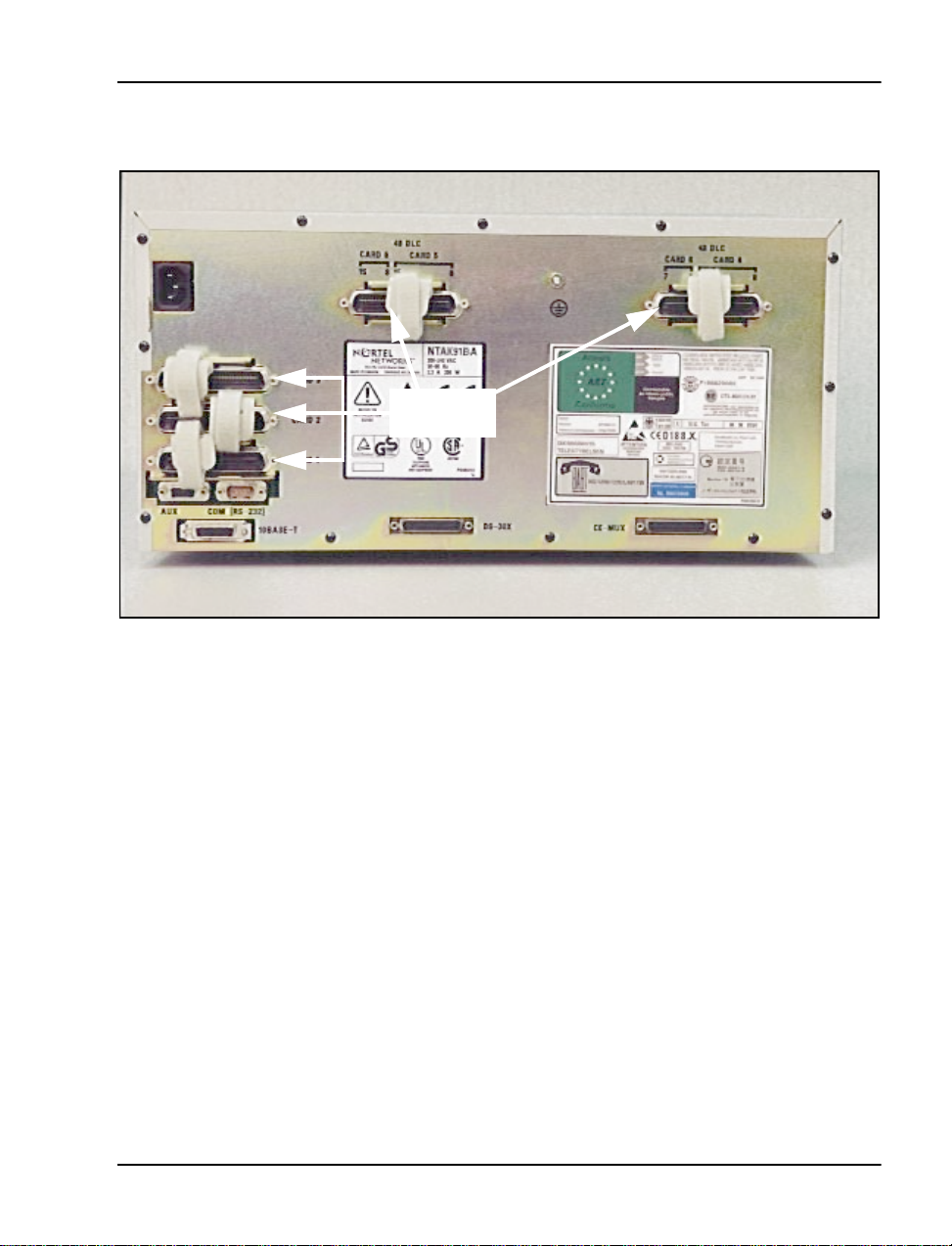
Figure 2
25-pair cable conne ctors on the back of the Main Chassis
25-pair
connectors
The Auxiliary (AUX), Serial Data Inte rface (SDI), and Ethernet connectors
are on the back left-hand side of the Main Chassi s. See Figure 3.
The AUX port connects auxiliary equipment, such as a Power Failure
Transfer Unit (PFT U), to the Option 11C Mini. The SDI connector in the
Main Chassis interfaces three SDI ports using a three-port SDI cable. The
Ethernet conne ctor in the Main Chassi s provide s a 10 Mbit Eth ernet port. The
Ethernet port accepts an industry-standard Medium Acce ss Unit (MAU).
Insert the Ethernet cable into this MAU.
The back of the Main Chassis also contains connec tors for connecting the
Main Chassis and the Chassis Expander. These connectors are for the
DS-30X and CE-MUX connections. See Fi gure 3.
The power connect or is at th e back o f the chass is on th e upper l eft-han d side .
See Figu r e 3. S e cu r e th e po w er co r d with a c ab l e ti e.
Option 11C Mini Planning and Installation Guide
Page 30
Page 30 of 332 Chapter 2 — Identifying the Option 11C Mini equipment
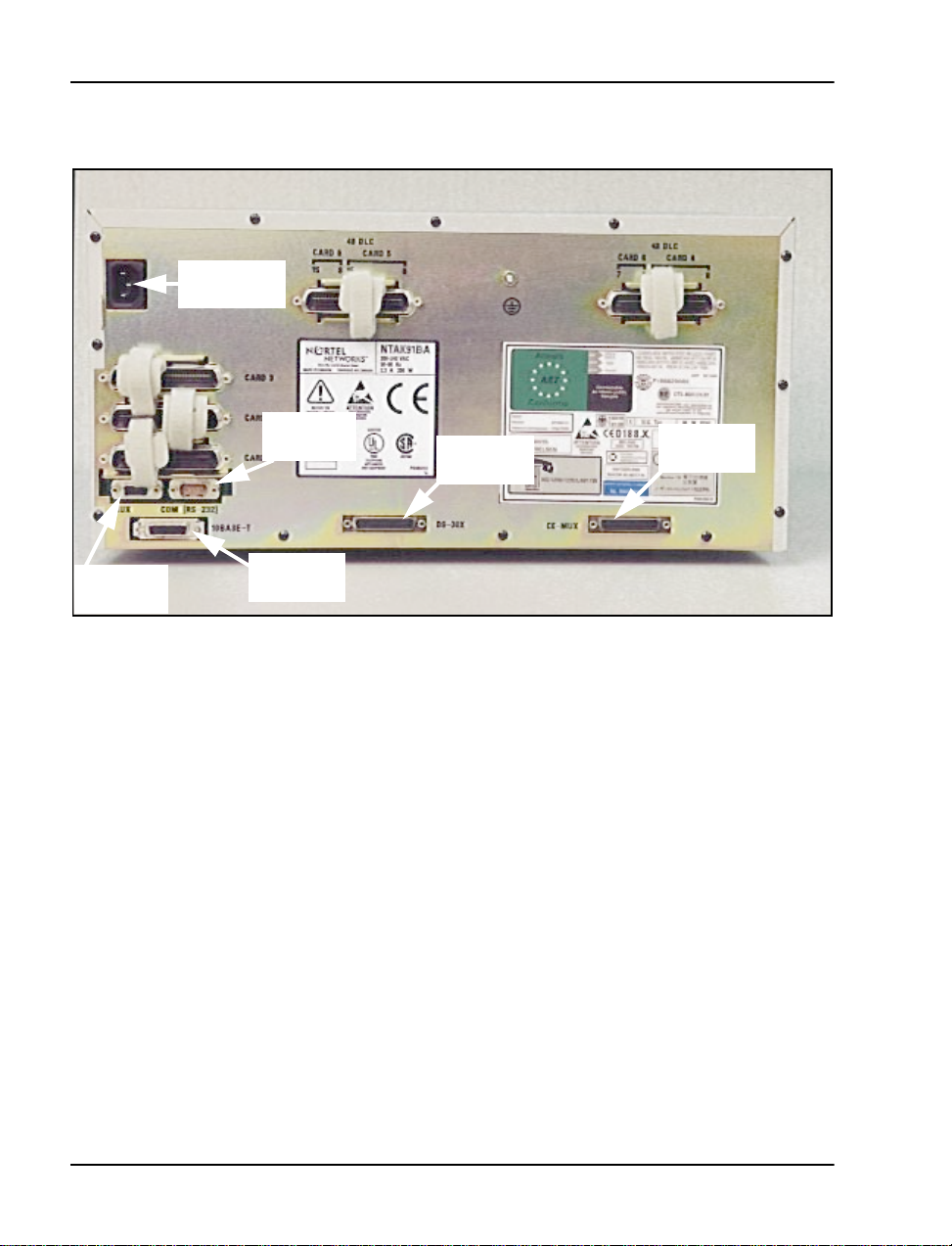
Figure 3
Connectors on the back of the Main Chassis
Power cord
connector
Auxiliary
connector
SDI
connector
Ethernet
connector
DS-30X
connector
CE-MUX
connector
553-3021-209 Standard 3.00 April 2000
Page 31

Chapter 2 — Identifying the Option 11C Mini equipment Page 31 of 332
Figure 4 shows the connectors on the back of the Chassis Expander.
Figure 4
Connectors on the back of the Chassis Expander
Power cord
connector
Cooling
The NTDK91 Main Cha ssis and t he NTDK92 Chass is Expa nder ha ve force d
air cooling. As a result, you can install the chassis in a horizontal or vertical
position. The fa n inside the chas sis is controlled by heat. It runs at a reduced
speed at room temp erature.
Power supply
The Option 11C Mini univers al power supply uses AC input. The power
supply is factory installed in the chassi s. The power supply is not cust ome r
replaceable. The Option 11C Mini system does n ot s upport DC input.
25-pair
connectors
Do not block chassis ventilation.
DS-30X
connector
CAUTION
CE-MUX
connector
Option 11C Mini Planning and Installation Guide
Page 32

Page 32 of 332 Chapter 2 — Identifying the Option 11C Mini equipment
Power switch
There is a p o w er switch on the front of the NTDK91 Main Ch assis and th e
NTDK92 Chassis Expander. Use this switch to turn the Option 11C Mini
power on and off. See Figure 5 on page 34.
Power status indicator
There is a power status indicato r (LED) on the fron t cove r (top left-hand
corner) of th e M ai n Ch assis and th e Ch a s si s E x pa n d er . Wh en th e LED is
green, the power i s in operation . When the LED is off, there is a power failure
of one of the power outputs. See Figure 5 on page 34.
Power supply DIP switch settings
Use a DIP switch to set ringing voltages, ringing frequencies, and message
waiting voltages. See Table 2 and Figure 5 on page 34 for all DIP switch
setting opt ions. Typical settings are shown for the following regions:
• “Asia Pacific/Cala power supply DIP switch settings” on page 33
• “Europe power supply DIP switch settings” on page 33
• “North American power supply DIP switch settings” on page 34
Table 1
Power supply DIP switch settings
Ringing Frequency (Hz) Ringing Amplitude (Vrms) Message Waiting Lamp (VDC)
Switch
Setting
1 ON OFF ON 3 OFF ON ON ON 6 NOT USED
2 ON ON OFF 4 OFF OFF ON ON 7 OFF OFF ON
20 25 50
Switch
Setting
5 OFF OFF OFF ON 8 OFF ON X
70 75 80 86
Switch
Setting
-120 -150 Disable
553-3021-209 Standard 3.00 April 2000
Page 33

Chapter 2 — Identifying the Option 11C Mini equipment Page 33 of 332
Table 2
Asia Pacifi c/Cala power supply DIP switch settings
In the Asia Pacific/ Cala region, usage of the high voltage Message Waiting
Lamp is optional. The following ta ble shows the settings for 25Hz, 75V and
-150V for the Message Waiting Lamp.
Ringing Frequency (Hz) Ringing Amplitude (Vrms) Message Waiting Lamp (VDC)
Switch
Setting
1 OFF 3 ON 6 NOT USED
2 ON 4 OFF 7 OFF
20 25 50
Switch
Setting
5 OFF 8 ON
70 75 80 86
Switch
Setting
-120 -150 Disable
Table 3
Europe power supply DIP switch settings
In Europe, usage of the high voltage Message Waiting Lamp is not allowed.
The following table shows the settings for 25Hz , 75V and the Message
Waiting Lamp is Disabled.
Ringing Frequency (Hz) Ringing Amplitude (Vrms) Message Waiting Lamp (VDC)
Switch
Setting
1 OFF 3 ON 6 NOT USED
2 ON 4 OFF 7 ON
20 25 50
Switch
Setting
5 OFF 8 ON
70 75 80 86
Switch
Setting
-120 -150 Disable
Option 11C Mini Planning and Installation Guide
Page 34

Page 34 of 332 Chapter 2 — Identifying the Option 11C Mini equipment
Table 4
North American power supply DIP switch settings
In North America, usage of the high voltage Message Waiting L amp is
optional and requires -150V when enable d. The following table shows the
settings for 20Hz, 86V and the Message Waiting Lamp is disabled.
Ringing Frequency (Hz) Ringing Amplitude (Vrms) Message Waiting Lamp (VDC)
Switch
Setting
1 ON 3 ON 6 NOT USED
2 ON 4 ON 7 ON
20 25 50
Switch
Setting
5 ON 8 ON
Set the dip switches before the system powers up.
Note:
70 75 80 86
Switch
Setting
-120 -150 Disable
Figure 5 shows the power s witch, power status indicator, and DIP switch
settings.
Figure 5
Front of chassis
Power status
indicator
Power
switch
DIP switch
settings
553-3021-209 Standard 3.00 April 2000
Page 35

Chapter 2 — Identifying the Option 11C Mini equipment Page 35 of 332
Reserve power supply
You can use an Uninterruptible Power Supply (UPS) to provide a backup
power supply for the NTDK91 and the NTDK92 chassis . A UPS provides a
continuous AC powe r supply. Install the UPS unit according to the
manufacturer’s instruct ions. Refer to “Power consumption worksheets for the
Option 11C Mini system” on page 64. This section contains worksheets to
help you determine the power draw for the UPS.
Circuit cards
The Option 11C Mini intr oduces the NTDK97 Mini System Contro ller
(MSC) card and the NTDK16 48-port Digital Line Card. This section
provides a short overview of these two cards. For more inform ation about
these cards and the other circuit cards supported on the Option 11C Mini,
refer to “Chapter 12 — Insta lling the circuit cards ” on page 147.
NTDK97 Mini System Controller card
The NTDK97 Mini System Controller (MSC) card is based on the
Option 11C NTDK20 Small System Controller (SSC) card. The MSC card
includes a Central Processing Unit (CPU) which handles call processing for
the system. The MSC card also i n cludes an Etherne t controller, storage for
system and customer da ta, and syste m mem ory.
The MSC card stores system and customer data. This ca rd is programmed
with system s oftware before it is shipped to the c ustomer. Ad ditional memory
on the MSC card temporarily stores and processes automated routines and
user-programmed commands. The MSC card also keeps a copy of customer
files in the event of data loss on the Backup Flash Drive.
You must install the MSC card in Slot 0 of the Mai n Ch assis.
Security Device
The MSC card is equipp ed with a socket. This socket ho ld s the Secu r i ty
Device. Each new Option 11C Mini system comes with a Security Device.
You must attach the Security Device to the MSC card during initial
installation.
PCMCIA interface
The NTDK97 MSC ca rd ha s a 2-sl ot PCMCIA inte rface soc ket l ocate d o n its
faceplate. You can insert a S of tware Delivery card into the socket. Use the
Software Delivery card for software upgrades on an existing Option 11C
Mini system. You can also use this socket for creating an external backup
copy of the customer database.
Option 11C Mini Planning and Installation Guide
Page 36

Page 36 of 332 Chapter 2 — Identifying the Option 11C Mini equipment
NTDK16 48-port Digital Line Card
The NTDK16 48-port Digit al Lin e Card prov ides an inte rface t o a maximum
of 48 digital integrated voice and 48 data ports. The NTDK16 Digital Line
Card is functionally equivalent to three NT8D02 Digital Line Cards.
Note 1:
Chassis.
Note 2:
Option 11C Mini system to operate.
Only place th e NTDK16 Dig ita l Lin e Card i n slot 4 of the Mai n
The NTDK16 Digital Line Card is not required for the
Telephones and Attendant Consoles
The following i s a list of t he telep hones and Atten dant Consol es supporte d by
the Option 11C Mini:
• Analog (500/2500 type) telephones, with or without message waiting
lamps
• Meridian Digital Tele phon es (M2006 , M2008, M2 009, M2018, M2112 ,
M2216, M2616, and M3000)
• Meridian Digital Telepho nes (M3110, M3310, and M3820)
The M3110, M3310, and M3820 Meridi an Digital Telephon es are
Note:
available in Europe only.
• Meridian Digital Telepho nes (M3901, M3902, M3903, M3904, and
M3905)
Only the M3901 an d th e M3 905 Merid ian Digi ta l Te lephone s are
Note:
supported in Europe.
• M2616 or M2216 Cent ral Answering Position (CAP). These telephone s
must have an ACD LCD display installed to functi on as a CAP
telephone.
• Meridian 2250 (TCM) Attendant Consoles
553-3021-209 Standard 3.00 April 2000
Page 37

Chapter 2 — Identifying the Option 11C Mini equipment Page 37 of 332
Cables and wires
Table 5 lists the Option 11C Mini cable kits and their contents.
Table 5
Option 11C Mini cable ki ts
Cable or wire Purpose/description
NTDK88 Main cable kit
NTBK48 three-port SDI cable The NTBK48 connects e quipment, s uch as
NTAK1104 AUX cable The NTAK 1104 connects a PFTU to a
A0601396 F-M DCE to DTE
converter
A0601397 F-F DCE to DTE
converter
A037683 Ferrite filter
NTDK89 Chassis Expander cable kit
NTDK95 CE-MUX/DS-30X bus
cable
NTTK15 cable kit f or Australia/New Zealand
A0386023 power cord for
Australia and New Zealand
A0376837 Ferrite filter
NTTK22 cable kit f or Denmark
A0386026 power cord for
Denmark
A0376837 Ferrite fil ter
TTYs and mod ems to t he Opti on 1 1C Mini.
Use the NTBK48 with the NTDK97 MSC
card.
system chassis.
You can use the A0601396 when
connecting SDI ports to equipment, such
as TTYs and modems.
You can use the A0501397 when
connecting SDI ports to equipment such
as TTYs and modems.
The NTDK95 connects the Main Chassi s
to the Chassis Expander. You need two of
these cables to connect the Main Chassis
and the Chassis Expander.
Length: 2 ft (610 mm)
The A0386023 connects a system chass is
to a 220 V AC commercial power source.
Length: 8 ft (2438 mm)
The A0386026 connects a system chass is
to a 220 V AC commercial power source.
Length: 8 ft (2438 mm)
Option 11C Mini Planning and Installation Guide
Page 38

Page 38 of 332 Chapter 2 — Identifying the Option 11C Mini equipment
Table 5
Option 11C Mini cable kits (Continued)
Cable or wire Purpose/description
NTTK16 cable kit f or Europe
A0381307 power cord for
Europe
A0376837 Ferrite filter
NTTK14 cable kit for North America
A0317094 power cord The A0317094 connects a system chass is
NTTK17 cable kit f or Switzerland
A0386024 power cord for
Switzerland
A0376837 Ferrite filter
NTTK18 cable kit f or the UK
A0381306 power cord for the UKThe A0381306 connects a system chass is
The A0381307 connects a system chass is
to a 220 V AC commercial power source.
Length: 8 ft (2438 mm)
to a 110 V AC commercial power source.
Length: 9 ft 10 in. (3000 mm)
The A0386024 connects a system chass is
to a 220 V AC commercial power source.
Length: 8 ft (2438 mm)
to a 220 V AC commercial power source.
Length: 8 ft (2438 mm)
Table 6 lists miscellaneou s c ables and wires used with the Option 11C Mini.
Table 6
Option 11C Mini miscellaneous cables and wires
Cable and wire Purpose / description
A0379411 powe r cord
(International )
NE-A25B 25-pair cab le The NE-A25B connect s Peripheral
NTAK19FA/FB cable The NTAK19FA/FB i s a four-port SDI
553-3021-209 Standard 3.00 April 2000
The A0379411 connects the chassis
to a 220 V AC commercial power
source
Length: 8 ft. 2 in. (2492 m m)
Equipment cards to the cross-c onnect
terminal. NE-A25B con nectors are on
the back of each chassis.
cable used with the NTAK02 circuit
card (see Note 1).
Page 39

Chapter 2 — Identifying the Option 11C Mini equipment Page 39 of 332
Table 6
Option 11C Mini miscellaneous cables and wires (Continued)
Cable and wire Purpose / description
NTAK19EC cable The NTAK19EC is a two-port SDI
cable used with the NTAK03 circuit
card.
NTAK1108/1118 9-to-25 pin
RS232 converter cab le
A0378652 F-F DCE to DTE
conv erter, or A0381016 F-M
DCE to DTE converter
NTBK04 1.5 Mbit DTI/PRI
carrier cable (A0394216)
The NTAK1108/1118 connects SDI
ports and terminals (see Note 1).
The A0378652 connects SDI ports to
equipment, such as TTYs and
modems.
The NTBK04 connects the NTAK09
1.5 Mbit DTI/PRI card to the Chann el
Service Unit (CSU). The NTBK04
carries Tx and Rx pairs to a standard
5-pin connector.
NTBK05AA/DA 2.0 Mbit
DTI/PRI carrier cable A0394217
The NTBK05AA/DA carries Tx and Rx
pairs to a standa rd 120-Ohm
D-connector (see Note 1).
NT8D7205 DTI/PRI carrier cable
NTBK05CA coaxial cable
NTBK05DA twist ed pair cable
NTAK10 2.0 Mbit DTI cable
NTAK79 2.0 Mbit PRI cable
These cables provide DTI/PRI
connections. The cables carry Tx and
Rx pairs to a standard 5-pin connector
(see Note 2).
NTAK50 2.0 Mbit PRI cable
25-pair inside wiring cables
equipped with amphenol-type
connectors
25-pair i nside wi ring cab les extend the
Peripheral Equipment connections
from the system chassis to the
cross-connect terminal, and connect
PFTUs.
#6 AWG (#40 Metric Wire
Gauge) insulat ed ground wire
2
10 mm
(#6 A WG) insula ted
ground wire (UK)
Option 11C Mini Planning and Installation Guide
The #6 A WG (#40 Met ric Wire Gaug e)
connects a system chassis to a
buildi ng ground source.
The 10 mm2 (#6 AWG) i nsulated
ground wire connects a system
chassis to a bui lding ground source.
Page 40

Page 40 of 332 Chapter 2 — Identifying the Option 11C Mini equipment
Table 6
Option 11C Mini miscellaneous cables and wires (Continued)
Cable and wire Purpose / description
#6 AWG (20 mm2) insulated
ground wire (Europe)
#8 AWG (10 mm
ground wire (Germany )
Cross-connect wire The cro ss-connect wire makes cross
Note 1:
specifications.
Note 2:
This cable is available in different versions, depending on local EMC
These ca bles are not supported under E M C specifications VL43.140P.
2
) insulated
The #6 AWG (20 mm2) insulated
ground wire connect s a chassis to a
buildi ng ground source.
The #8 AWG (10 mm2) connects a
chassis to a bui lding ground source.
connections at the cross-connect
terminal.
Miscellaneous items for installation
The following is a list of miscellaneous items that you can use as part of
Option 11C Mini system installation. Quantities needed depend on the site
and customer requirements:
• QUA6 Power Failure Transfer Units (PFTU) to transfer lines during a
power or system failure
• NTBK80 grounding block
• modems or Data Communication Equi pment (DCE) fo r remote access to
the system
• on-site Data Terminating Equipment (DTE) or TTY terminal for
accessing the system
• connecting blocks for the cross-connect terminal
• transformers and centralize d power supplies for items such as digit
displays on telephones
• optional equipment such as music sources, RAN machines, paging
equipment, and CDR devices
• NTAK92 Off-Premise Protection Module for connecting up to four
off-premise analog telephones
553-3021-209 Standard 3.00 April 2000
Page 41

Chapter 2 — Identifying the Option 11C Mini equipment Page 41 of 332
• additional Modem Eliminator (NULL Modem without hardware
handshakin g). The A0601 397 c onverte r may be requi red to i nte rface th e
DTE to the syst em.
• industry-standard Ethernet Medium Access Unit (MAU)
Differences between Option 11C Mini and Option 11C
Refer to Table 7 for a comparison of the Option 11C Mini and Option 11C
systems.
Table 7
Comparison of Option 11C Mini and Option 11C
Item Option 11C Mini Option 11C
Physical packaging Main Chassis NTDK91
Chassis Expander NTDK92
Two copper cabl es connect the
Main Chassis to the Chassis
Expander.
Capacity Main Chassis:
• 4 physical slots
• logical slots (slots 1-6)
Chassis Expander
• 4 physical slots
slots (slots 7-10)
Supports up to 144 lines Supports up to 700 lines
Chassis in stallation Four chassis in stallation options:
• vertically on a wall
• horizontally on a wall
• rack/cabinet
•table
Cooling Forced air, t hermall y controlled
cooling
(F an installed inside chassis)
Main cabinet NTAK11
Fiber-optic cable connects the
Main Cabinet to the Expansion
Cabinet (u pgraded systems may
still have copper cabl e
connection) .
Main Cabinet:
• 10 physical slots
(slots 1- 1 0)
Expansion Cabinet
• Up to 4 additional NTAK11
cabinets can be connect ed
with fiber-optic cable
(slots 20-50)
Two chassis installation options:
•wall
• floor
conv ection cooling
Option 11C Mini Planning and Installation Guide
Page 42

Page 42 of 332 Chapter 2 — Identifying the Option 11C Mini equipment
Table 7
Comparison of Option 11C Mini and Option 11C (Continued)
Item Option 11C Mini Option 11C
Power • AC power only
• universal power supply
factory ins talled in chassis
• not field replaceable
• power swit ch on chassis
Reserve power UPS only UPS and battery backup
Cables New NTDK95 cable in troduced
(Two NTDK95 cables connect the
Main Chassis to the Chassis
Expander)
Auxi li ary cable used only for
PFTU.
Ethernet • standard 15-pin AUI on
chassis
• NTDK27 ethernet adapter
cable n ot requ ired
• no jumper settings
required
CPU NTDK97 Mini System Controller
(MSC)
• PCMCIA interface
•3 SDI ports
• 30 channels TDS
• 8 units DTR or XTD
• 4 units of MFC,
MFE/MFK5/MFK6/MFR or
8 DTR/XTD units
• AC or DC power
• NTDK78/NTDK75/
NTAK04/NTAK05
• field replaceable
Auxili ary cabl e u sed f or PFTU o r t o
provide power for Attendant
Console.
• NTDK27 ethernet adapter
cable required
• May need to set J7 jumper
NTDK20 Small System Controller
(SSC)
• PCMCIA interface
•3 SDI ports
• 30 channels TDS
• 8 units DTR or XTD
• 4 units of MFC,
MFE/MFK5/MFK6/MFR or
8 DTR/XTD units
• Maximum 16 conference
channels
553-3021-209 Standard 3.00 April 2000
• 32 channels on SSC
• 16 channels per fiber-optic
daughterboard
Page 43

Chapter 2 — Identifying the Option 11C Mini equipment Page 43 of 332
Table 7
Comparison of Option 11C Mini and Option 11C (Continued)
Item Option 11C Mini Option 11C
• C: drive on NTDK97 is 16
Mbytes
• Z: drive on NTDK97 is 1.5
Mbytes
• NTDK97 program store is
32 Mby te s
• DRAM on NTDK97 is 16
Mbytes
Daughterboards None • NTDK21/NTDK81
Software X11 Release 24.24 and later X11 Release 22 and later
Software
Installa ti on
Software is preprogrammed on
MSC card.
Option 11C Mini uses the sam e
feature sets, ISM paramet ers, and
key code format as the Option 11C.
• C: drive on
NTDK21/NTDK81 is 8
Mbytes
• Z: drive on NTDK20 is 1.5
Mbytes
• NTDK21 program store is
24 Mbytes
• NTDK81 program store is
32 Mbytes
• DRAM - 8 or 16 Mbytes
SIMM
Software Daughterboard
• NTDK22, NTDK24,
NTDK79, NTDK84, and
NTDK85, Fiber-opti c
Expansion Daughter boards
Software is preprogrammed on
Software Daughterboard.
Software upgrades Per form software upgrades using
the same PCMCIA card as the
Option 11C.
IPE and CE cards The Option 11C Mini supports the
same IPE and CE cards as the
Option 11C
The supported CE cards are: PRI,
DTI, PRI2, DTI2, SDI/DCH,
TDS/DTR, MISP
Only slots 1-3 in t he Main Ch assi s
support CE cards.
Option 11C Mini Planning and Installation Guide
Per form Software upgr ades using
a PCMC IA ca rd.
Only slots 1-9 in the Main Cabinet
support CE cards.
Page 44

Page 44 of 332 Chapter 2 — Identifying the Option 11C Mini equipment
Table 7
Comparison of Option 11C Mini and Option 11C (Continued)
Item Option 11C Mini Option 11C
48-port Digital Line
Card
Only the Option 11C Mini system
supports the NTDK16 48- port
DLC.
• only install th is ca r d in slo t
4 of the Main Chassis
• configured as slots 4, 5,
and 6
The NTDK16 Digital Line Card
Note:
is not required for the Option 11C Mini
system to operate.
Meridian Mail Only slot 10 in the Chassis
Expander supports Meridian Mail
Mini.
NTDK16 not supp o rt ed
Slot 10 in the Main Cabinet
supports Meridian Mail Card
Option and Meridian Mail
Enhanced Card Opt ion.
553-3021-209 Standard 3.00 April 2000
Page 45

68
Page 45 of 332
Chapter 3 — System and site requirements
Before you ins tall the Opti on 11C Mi ni syst em, mak e sure that t he sit e meets
all environmental, grounding, power, and cross-connect terminal
requirements.
Environmental requirements
The environment in which the Meridia n 1 Option 11C Mini sys tem operates
must meet the following general conditions:
• Make sure that the room is cl ean and well ventilated. Ea ch ch assis can
dissipate up to 370 Watts of power. There must be enough vent ilati on in
the equ ip ment room t o maintain th e temperature at an acceptable level.
• For installed chassi s, ma intain the temperature between 0° and 45° C
(32° and 113° F).
• Maintain the humidity between 5% and 95% non-condensing.
• Select a location for installing the equipment that is not subject to
constant vi bration.
• Locate the equipment at least 12 ft (3660 mm) away from sources of
electrostatic, electromagnetic, or radio frequency interference. These
sources can include:
— power tools
— appliances (such as vacuum cleane rs)
— office business machines ( such as copying mac h ines)
— all electric motors
— electrical transf or mers
Option 11C Mini Planning and Installation Guide
Page 46

Page 46 of 332 Chapter 3 — System and site requiremen ts
Earthqua ke bracing requireme nts for chass is insta lled on a wall in a vertical position
IMPORTANT
The following earthquake bracing guidelines meet the requirement s
for the state of California specifications in the United States. Other
areas or countries can have different requirements.
CAUTION
For earthquake bracing, you must install the Option 11C Mini chas sis
on a wall in a vertical position.
The earthquake brac ing method for the Opti on 11C Mini does not
Note:
guarantee th at the system will continue to operate during or after an
earthquake.
To earthquake brace your system, use a piece of 3/4 in. (20 mm) plywood as
a backboard. Fasten the plywood to the wall wi th a minimum of six fa steners.
(Refer to Table 9 on page 47 for a description of the appropriate fasteners.)
Fasten the chassis to the ba ckboard.
Table 8 identifies the maximum acceptable wall height for different types of
stud wall construction in areas prone to earthquakes.
Table 8
Minimum wall requir ements – stud construction
Wall Studs
2 in. x 4 in. wooden studs 16 in. or 24 in. 10 ft
2 in. x 6 in. wooden studs 16 in. or 24 in. 16 ft
3 5/8 in. 20 gauge metal studs 16 in. or 24 in. 12 f t
3 5/8 in. 18 gauge metal studs 16 in. or 24 in. 16 f t
553-3021-209 Standard 3.00 April 2000
Spacing off
center
Maximum Height of
Wall
Page 47

Chapter 3 — System and site re quirements Page 47 of 332
Table 9
Minimum fastener requirements
T ype of wal l Fasteners
Wooden studs #10 wood screws Embedded a minimum of 1
in. in wood studs
Metal studs # 14 sheet metal
Concrete
(2000 PSI)
Masonry 1/4 in . R amset
Fasten the mounting bracket for e ach chassis to the piece of pl ywood with the
five, 1 in. #14 screws supplied with the bracket.
“Chapter 8 — Bracing the Option 11C Mini agains t earthquakes” on
page 105 of this guide contains a detailed procedure for earthquake bracing
Grounding requirements
Failure to follow grounding recommendations can result in a system
installation that is:
• unsafe for personnel working on, or using the equipm ent
• not protected correctly from lightning or power transients
Embedded a minimum of 1
screws
1/4 in. HILTI KB-II Embedded a minimum of
Redhead Dynabolt
sleeve anchor
in. in metal studs
1 1/8 in.
WARNING
.
• subject to s ervice interruptions
Before you install an Option 11C Mini and before you apply AC power,
measure the impedanc e of the building ground refere nce. An ECOS 1023
POW-R-MATE, or another meter like the POW-R-MATE, is acceptable for
this purpose. If the ground path connected to th e Option 11C Mini has an
impedance of 5 Ohms or more, make better grounding arrangements. Make
any improvement s to the grounding s ystem before you install the Opti on 11C
Mini.
Option 11C Mini Planning and Installation Guide
Page 48

Page 48 of 332 Chapter 3 — System and site requiremen ts
The following are addi tional grounding requirements:
CAUTION
Never connect the single point ground conduc tor from the Option 11C
Mini system to structural steel members or electrical conduit. Never
tie this conductor to a ground source or grounded electrode that is not
hard-wired to the building reference conductor.
• Ground conductors for the Option 11C Mini system:
— must not be smaller than #6 AWG (#40 metric) at any point (see
Table 10 on page 49. This table provides a list of grounding wire
requirements spec ific to som e areas)
— must be routed through the same condui t as the phase conductors
that serve the system
— must not be smaller than any phase conductor in the same conduit
— do not carry current under normal operating conditions
• All ground conductors in the building:
— must be isolated from the neutral bus exc ept at the service entrance
to the bu ilding
— must be hardwired to the main ground refere nce
• Avoid spliced conduc tors. Continuous conductors have lower
impedance, and they are more reliable than spliced conductors.
553-3021-209 Standard 3.00 April 2000
Page 49

Chapter 3 — System and site re quirements Page 49 of 332
• All conductors must terminate in a permanent way. Make sure all
terminations are easily visible and ava ilable for maintenan ce pur poses.
• Tag ground connections with a clear message such as “CRIT ICAL
CONNECTION: DO NOT REMOVE OR DISCONNECT”.
Table 10
Area-specific grounding wire requirements
Area Grounding wire requirements
Germany #8 AWG (10 mm
Other areas in Europ e not smaller th an #6 AWG (16 mm
point
UK two green/y ellow wires no th inner than two
10 mm
2
2
) green/yel l ow w i re
2
) at any
CAUTION
For an installe d Option 11C Mini, the impedance of the link between
the ground post of the Main Chassis and the single point ground to
which it connects must be less tha n 0.25 Ohms.
CAUTION
Trans ients in supply conduct ors and ground systems can damage
integr ated circuits. This da mage can result in unreliable Option 11C
Mini operation. Damage caused by transients is not always
immediately apparent. Degradation ca n occur over a period of time .
Option 11C Mini Planning and Installation Guide
Page 50

Page 50 of 332 Chapter 3 — System and site requiremen ts
Ground bus isolation (Canada and the United States)
According to the ex ce ption to article 384-20 in the United States Natio nal
Electrical Code (NEC), a panel’s ground bus can be isolated from the
housing. Thi s e xception applies provided that the panel is not at the ma in
service e ntranc e. This exc eptio n applies to some C anadian lo catio ns also . For
more information about ground bus isolation, refer to local electrical codes.
CAUTION
Do not isolate the ground bus from the housing unles s permitted by
local electrical codes. Do not perform work inside electrical panels
unless you are a qua lified electrician. Do not try to remove bonding
conductors without approval from qualified personnel.
CAUTION
Route ground conductors, between supply panels, through the same
conduit as the supply conductors. This safety requirement is part of
both the National Electrical Code (NEC) an d the Ca nadian Electrical
Code (CEC).
Single Point Grounding (SPG)
Correct grounding of communications systems is necessary for protecting
equipment from th e hazards of surge a nd noise int erference. The Sing le Point
Grounding (SPG) method of protecting communications equipment is the
Nortel Networks standard for Meridian 1 systems.
The requirements for Single Point Grounding are in the following major
categories: Safety, Protection, EMC, Installation and Maintenance,
Powering, and Advances in Tech nology.
Safety
For a safe working environm ent, your grounding system must be abl e to
dissipate unwanted surge energies, suc h as lighting on the outside plant. The
grounding sys tem must be desi gned so that fu se or breakers ope rate to di srupt
the excessive current f lo w caused by a power fault.
553-3021-209 Standard 3.00 April 2000
Page 51

Chapter 3 — System and site re quirements Page 51 of 332
Protection
Correct grounding is a necessary component of the protection system for
equipment. T his groundi ng include s grounding for outs ide plan t cable shields
and protecto rs , and the grounds for fr am ework, battery, and logic references.
EMC
To make sure that there is good e mission and susceptibility performance of
the equipment , yo u must c onside r the E lect romagne tic C ompati bilit y (E MC)
grounding requirements.
Installation and Maintenance
A grounding syst em is c ost eff ectiv e to insta ll and mai nta in when it is pa rt of
the initial electrical installation for the customer’s premises. If you try to
correct violations of national codes af ter the initia l installation, it is both
difficult and costly.
Powering
The grounding syst em must consider the power options for the equipment.
The grounding syst em must consider if the equipment is backed up with an
Uninterruptible Power Supply (UPS ). Consider the grounding and powering
of all equipment that is part of the telecommunications system as one large
system. Perform the installation taking this information into consideration.
Advances in Technology
The component density on circuit cards continues to increase be cause of the
miniaturization and multi-layering of printed circui t boards. The operating
speeds of the integrated circuits are ever increasing. Grounding provides
protection for these components, and is very im portant.
The SPG of a system is the point at which telecommunications equipment
bonds to the ground. A copper busbar normally acts as the system SPG.
Option 11C Mini Planning and Installation Guide
Page 52

Page 52 of 332 Chapter 3 — System and site requiremen ts
You can use any of the following busbars as a system SPG:
• building principal ground, normally in building with one floor
• floor ground bar, normally in buildi ngs with m ore than one floor
• dedicated SPG bar bonded to the building grounding system
• a section of the battery return bar of the power plant
You can configure subsystems of a telecommu nications syste m, suc h as
groups of frames or equipm ent, as separate single poi nt ground entities
connected in a star configuration to the system SPG.
Figure 6
Single point gr ounding
Various Communication Subsystems
553-3021-209 Standard 3.00 April 2000
SPG
553-9479
Page 53

Chapter 3 — System and site re quirements Page 53 of 332
Grounding method
To prevent ground loops, power all chassis from the same dedicated
power panel. Ground all Main Chassis to the power pane l through the
grounding block. Ground the Chassis Expander to the Main Chassis.
The method of grounding used for the Opt ion 11C Mini d epends on whether
the same service panel powers all chassis.
The following three grounding scenarios ar e possible:
A system with one chassis
1
A syst em wi th mor e th an o ne chas si s, p ow ere d b y th e sa me serv ic e p ane l
2
A system w ith more than one chassis, powered b y di fferent service
3
panels
A system with one chassis or multiple chassis powered by one
service panel
For each Main Chassi s, conne ct a # 6 AWG (#40 Metri c Wire Gauge) grou nd
wire from the chassis to the NTBK80 grounding block. See Table 10 on
page 49 for grounding wire requi remen ts spec ific to some a reas . Connect th e
grounding blo ck to a ground s ource (t he ground bus in th e AC powe r service
panel).
CAUTION
Consider the Main Chassis and the Chassis Expander as the same ground.
Jumper the ground wire from the Chassis Expa nder to the Main Chassis and
then back to the grounding block.
Option 11C Mini Planning and Installation Guide
Page 54

Page 54 of 332 Chapter 3 — System and site requiremen ts
Chassis powered by different service panels
For each Main Chassi s, conne ct a # 6 AWG (#40 Metri c Wire Gauge) grou nd
wire from the chassis to the NTBK80 grounding block. See Table 10 on
page 49 for grounding wire requirements specific to s ome areas. If any
chassis cannot be powered from the same service panel, gr ound it separately
from the other chassis back to the service panel that supplies it. Power each
Main Chassis and Chassis Expander pair from the same service panel.
Note 3:
method that you use for a system with one chassis.
Note 4:
to an NTBK80 grounding block or through a Krone Test Jack Frame.
Grounding multiple pieces of equip ment in a rack/ca binet
You must ground each piece of equipment in a rack/cabinet. If a piece of
equipment does not have a ground lug, then ground the whole rack/cabinet.
If a chassis req uires a separa te ground, ground it usi ng the same
In the UK, you can conn ect the gro unding wire from the chassis
Conduit req uir em ent s
Conductive conduit linking panel s and equipment are legal for use as a
grounding network in most countries. For all sy st em ground paths for the
Option 11C Mini, us e the correct size of insula ted copper conductors routed
inside conduit when possible. A ground link that depends on conduit ca n
defeat the improvements made by installing de dicated panels and
transformers . The following are the reasons why:
• Personnel who service diff ere nt equi pment can s eparate co nduit li nks. If
this separation occurs between the Option 11C Mini system and the
building grou nd reference, the conduit cannot provide a ground path.
This situation is a hazardous.
• Metal conduit often corrodes, especially at threaded connections.
Corrosion increa ses resi stan c e. This pro ble m becomes worse when
multiple li nks are involved. If you apply paint over the conduit, it is
possib l e th a t th e co r r o s i on pr o cess wi ll occur mo re quickly.
• Always fasten conduit to secure surfaces. Often, condui t is bolted to
structura l st ee l me mb ers, which can function as ground conductors to
noisy equipment (for example, compressors and motors). The co upling
of these noisy si gnals into the Option 11C Mini grounding system can
damage its performance. The resulting intermittent malfunctions can be
difficult to trace.
553-3021-209 Standard 3.00 April 2000
Page 55

Chapter 3 — System and site re quirements Page 55 of 332
Commercia l po w e r requir ement s
The Option 11C Mini system is available with AC-power only.
The optimal installation of the AC-power ed Option 11C Mini system
includes a di rect c onne ction t o th e ele ctric al syst em in t he b uilding , pr ovided
some requirement s a re met. Refer to AC-powered insta llation later in thi s
chapter for detai led information. The Main Chassi s and Chassis Expander can
share the same electrical breaker .
You can use an approved isolation transformer for AC-powered systems
when meeting the optimum requirements is not possible or is too expensive.
See “Alternative AC-powered installation” on page 58.
Refer to “Power consumption worksheets for the Option 11C Mini system”
on page 64 to determine the power consumpt ion of the Option 11C Mini.
AC power installation for systems installed on a wall or table
Use a dedicated AC ser v ice panel with the Option 11C Mini system. Do not
connect equi pme nt that is not related to the Option 11C Mini to this panel.
Keep all light ing, fans, motors, air conditioning equipment, and the like, as
“electrica lly separate” from the Option 11C Mini system as possible. The
Main Chassis and Chassis Expander can share the same AC breaker.
AC power installation for systems installed in a rack/cabinet
If other data communications equipment is in the same rack/cabinet as the
Option 11C Mini, power each piece of equipment from an isolated ground
outlet. The same service panel must service all outlets.
Power from each outlet mus t meet the input requirement s of at least one
Option 11C Mini power supply, as listed in Tables 11 through 13. Check
power requirement s for ot her s ystem equipment. Install additional outl ets if
you need to.
Option 11C Mini Planning and Installation Guide
Page 56

Page 56 of 332 Chapter 3 — System and site requiremen ts
Table 11
AC input requi rements for each NTDK91 and NTDK92 (North America)
Recommended: 100-120 v olts
Voltage
Maximum limits: 90 and 132 volts
Single phase
Frequency
Power
50-60 Hz
550 VA maximum
(I/P max)
Outlet Type
120 volt, 15 Amp supply
Table 12
AC input requi rements for each NTDK91 and NTDK92 (Europe and UK)
Recommended: 208/220 v olts
Voltage
Maximum limits: 180 and 250 volts
Single phase
Frequency
50-60 Hz
Power
550 VA maximum
(I/P max)
Outlet Type
Note 1:
planni ng your power requireme nts.
Note 2:
must have a sy st em gro un d cond uctor.
As local power specification s vary, see a qualified local electrician when
The Supplied power must be sing le-phase 240 or three-phase 208 Y, and
208/240 volt, 15 Amp supply
553-3021-209 Standard 3.00 April 2000
Page 57

Chapter 3 — System and site re quirements Page 57 of 332
Table 13
AC input requi rements for each NTDK91 and NTDK92 (Germany)
Recommended: 230 vol ts
Voltage
Frequency
Power
(I/P max)
Fuse
Maximum limits: 180 and 250 volts
Single phase
50 Hz
550 VA maximum
16A
Outlet Type
Receptacles by DIN regulation
Site requirements
The following is a list of required site features f or an optimal Option 11C
Mini AC-powered system installation.
If a dedicated panel cannot provide the conditions listed below, use an
Isolation Transf ormer. Refer to “Alternative AC-powered installation” on
page 58.
• Dedicated circuit breaker panel
A dedicated circ uit breaker panel provide s power only to th e Option 11C
Mini system and its rela ted hardware, such as TTYs and printers
You can not always power a complete system from a singl e
Note:
circuit-breaker panel. For example, when chassis are located remotely.
• Insula ted copper ground condu ctor
Insulated copper ground conductor connects the ground bus in the
dedicated panel to the main service panel ground or building ground
reference. Route the insulated copper ground conductor through the
same conduit as the sup p ly conductors that feed the panel.
• Isol ated-ground receptacles
All outlets connected to the dedicated panel must be of the isola ted
ground type. Use a separa te circuit for each devic e con nected to the
panel. Outl ets that provi de servic e to the c hassis must be close enough s o
that the power cord can reach the chassis power supply.
• Isolated ground bus in the electrical panel, where permitted by local
codes
Option 11C Mini Planning and Installation Guide
Page 58

Page 58 of 332 Chapter 3 — System and site requiremen ts
Location of po we r ou t lets
The maximum distance between a power outlet a nd the system chassis
depends on the lengt h of the powe r cord. In North America, the power cord
is 9 ft 10 in. (3000 mm). In countries outsid e North America , the power cord
is 8 ft 2 in. (2490 mm).
Alternative AC-powered installation
If a dedicated panel c annot provide optimal conditions, use an Isolation
Transformer with the following characteristics:
• 120/208/240 VAC input, over-current protected at primary
• 120/208/240 VAC available at s econdary outputs, each
circuit breaker-protected
• Completely isolate primary and secondary windings from one another
• Approved for use locally as a stand-alone use r product (CSA, UL, or
other locally recognized clear markings)
• Capable of providing power to all Option 11C Mini system equipment
operating at the same ti me at full load
• Equipment not related to the Option 11C Mini system must not be
powered from a transformer that provides service the Option 11C Mini
system.
Uninterruptible Powe r Su ppl y
For backup AC power, you can use an Uninterruptible Power Supply (UPS)
to feed the Opti on 11C Mini . The power requ irement for a UPS is 550 VA per
system. The maximum power requirement for a Main Chassis and a Chassis
Expander on the same breaker is 1100 VA. Ins tall the UPS according to the
manufacturer’s instruct ions.
Isolation tr a nsf o rm e r ground
The transfor mer gr ound m ust have the following characteristics:
• Separate grounds for primary and seconda ry windings, rather than a
common ground
• A “clean” and permanent SPG re ference at the transfor mer secondary f or
the Option 11C Mini system
Make sure that the ground conductors inside the transformer are sized
correctly.
553-3021-209 Standard 3.00 April 2000
Page 59

Chapter 3 — System and site re quirements Page 59 of 332
Receptacles
Receptacle requirements are as follows:
• When installed on the wall, i nstall re cept acles wit hin rea ch of the cha ssis
power cords.
• All receptacles served by the secondary must be of the isolated ground
type
• The ground prong of each outlet must be connec ted by an insulated
conductor to the system SPG
If the trans former has an isolated secondary ground lug, use it as the SPG. If
it does not, use the chassis ground of the transformer as the Single Point
Ground.
Installing an Isolation Transformer
Transfor me rs wi t h pl ug ga b le po we r co rds:
Connect the power cords of all Option 11C Mini system equipment to the
1
outlets on the transformer secondary.
Secure an insulat ed conductor between the ground lug on the Main
2
Chassis of the Option 11C Mini and the SPG lug on the transformer.
Place a “DO NOT DISCONNECT” tag on it.
Do not fasten or ti e th is co nductor t o the power ca ble feedi ng the Option
11C Mini.
Power all equipment related with the Option 11C Mini from the
Note:
secondary of the tra ns f orm er only. Ground all equipment to the
secondary isolated ground lug. Do not conn ect equipment that is not
related to the Option 11C Mini system to the isolation transformer that
powers it.
Option 11C Mini Planning and Installation Guide
Page 60

Page 60 of 332 Chapter 3 — System and site requiremen ts
Power the tr ansfor mer p rimary t hrough a de dicat ed c ircuit . If the p rimary has
a pluggable cord, make an additional ground connection between the
Option 11C Mini SPG and a known building ground reference. This
connection is very important for safe and reliable operation.
CAUTION
Do not connect any system ground lines of the Option 11C Mini to
structural steel or water pipes, or other unreliable ground paths. Use a
ground point known to be “clean” and perma nent. Place a “DO NOT
DISCONNECT” tag on it. Figure 7 on page 61 shows the pluggable
cord connections.
553-3021-209 Standard 3.00 April 2000
Page 61

Chapter 3 — System and site re quirements Page 61 of 332
Figure 7
Typical pluggable cord Isolation Transformer wiring plan
Note 1
Shared
Panel
Neutral Bus
Gnd Bus
Note 3
Note 5
Note 9
•
Isolation
Transformer
••
•
••
Note 7
Note 8
Note 2
Note 6
Option 11
Cabinet
•
Gnd Lug
Notes:
1
Power source is site dependent. It may be from a shared panel or transformer. Wiring may vary
accordingly. Wiring to panel must be housed in conduit.
2
Make SPG at the transformer secondary. If the transformer secondary has no isolated secondary
ground lug, make SPG by connecting all system ground lines to the chassis lug on the transformer
case. An insulated ground connection must be made between the SPG and a known building ground
reference, as per Note 3.
3
Terminate the Option 11 SPG insulated ground conductor as near as possible to the main building
ground reference. Isolate the ground bus from panel housing if permitted by local codes. Conductor
should be minimum AWG #6 (metric #40) at all points.
Note 4
120V IG
Receptacle
240V IG
Receptacle
4
Wiring to receptacles must be in conduit unless they are mounted on the transformer case.
5
Connection can be made by metallic conduit. Additional copper conductor recommended.
6
Minimum AWG #6 (metric #40) insulated copper conductor connected to FGND lug on the Option 11
cabinet. Route separately from AC power cable.
7
Separate breaker required for each Option 11 Main cabinet. Breakers must be mounted on transformer
if the receptacles are. If they are in a panel served by the transformer secondary, all connections
between the receptacles and transformer must be in conduit. The Main Chassis and the Chassis
Expander can coexist on the same breaker.
8
Connect secondary neutral (X0) to system SPG.
9
Conduit required.
Option 11C Mini Planning and Installation Guide
553-8322.EPS
Page 62

Page 62 of 332 Chapter 3 — System and site requiremen ts
Transformers without pluggable power cords
If the transformer does not have a pluggable cord, hardwire the transformer
to an electrica l panel. Route all wires (including grounds) through a single
conduit.
Some electri cal c odes permit t he use of conduit as the only gr ound c ond uctor
between pieces of equipment.
Run a separate insulated ground con ductor through the c onduit to hold cha ssis
grounds together. Such a conductor maint ains the safety ground co nnection
in the event that the conduit becomes corroded or disconnected.
Run all ground lines thr ough the same conduit as the phase conductors that
serve the equipment . Figure 8 on page 63 shows the Isolation transformer
connections.
553-3021-209 Standard 3.00 April 2000
Page 63

Chapter 3 — System and site re quirements Page 63 of 332
Figure 8
Typical hardwired Isolation Transformer wiring plan
Note 1
Neutral Bus
Gnd Bus
Note 3
Shared
Panel
Note 5
Note 4
•
Isolation
Transformer
• •
•
••
Note 7
Note 8
Note 2
Note 6
Option 11
Cabinet
•
Notes:
1
Power source is site dependent. It may be from a shared panel or transformer. Wiring may vary
accordingly. Wiring to panel must be housed in conduit.
2
Make SPG at the transformer secondary. If the transformer secondary has no isolated secondary
ground lug, make SPG by connecting all system ground lines to the chassis lug on the transformer
case. An insulated ground connection must be made between the SPG and a known building ground
reference, as per Note 3.
3
Terminate the Option 11 SPG insulated ground conductor as near as possible to the main building
ground reference. Isolate the ground bus from panel housing if permitted by local codes. Conductor
should be minimum AWG #6 (metric #40) at all points.
Note 4
120V IG
Receptacle
240V IG
Receptacle
Gnd Lug
4
Transformer primary wires must be in conduit. Wiring to receptacles must be in conduit unless they are
mounted on the transformer case.
5
Connection can be made by metallic conduit. Additional copper conductor recommended.
6
Minimum AWG #6 (metric #40) insulated copper conductor connected to FGND lug on the Option 11
cabinet. Route separately from AC power cable.
7
Separate breaker required for each Option 11 Main cabinet. Breakers must be mounted on transformer
if the receptacles are. If they are in a panel served by the transformer secondary, all connections
between the receptacles and transformer must be in conduit. The Main Chassis and the Chassis
Expander can coexist on the same breaker.
8
Connect secondary neutral (X0) to system SPG.
Option 11C Mini Planning and Installation Guide
553-8323.EPS
Page 64

Page 64 of 332 Chapter 3 — System and site requiremen ts
Power consumption worksheets for the Option 11C Mini
system
Use the worksheets (Tables15 to 17) in this section to determine the power
consumption for the Option 11C Mini system. Refer to Ta ble14 for the
circuit card power consumption.
Table 14
Circuit card power consumption
Circuit card Type
NT6R16 Meri dian Mail Mini steady state 35W
NT5K02 Flexible analog line card 50% 26W
NT8D02 Digital line card 100% 25W
NT8D03 Analog line card 50% 26W
NT9D09 Message-waiting line card 50% 26W
NT8D14 U n iv ers a l tru n k car d DID-enabled 28W
NT8D15 E&M trunk card N/A 29W
NTDK16 48-port Digital Line Card 100% 75w
NTDK97 Mini System Controller N/A 15 w
NT AK02 SDI/DCH card N/A 10W
NT AK03 TDS/DTR card N/A 8W
NT AK09 1.5Mb DTI/PRI card N/A 10W
NT AK10 2.0 Mb DTI card N/A 12 W
NT AK79 2.0 Mb PRI card N/A 12 W
% active sets
(off-hook)
Power
consumption
NTBK50 2.0 Mb PRI card N/ A 12 W
NTBK22 MISP card N/A 12 W
553-3021-209 Standard 3.00 April 2000
Page 65

Chapter 3 — System and site re quirements Page 65 of 332
Table 15
Option 11C Mini power consumption: Main Chassi s
Slot Circuit card Type
1 NTDK97 MSC 15 w
2
3
4, 5, 6 NTDK16 48 port DLC 75w
Total
Table 16
Option 11C Mini powe r consum ption: Chassis Expander
Slot Circuit card Type
consumption
from Table 14
consumption
from Table 14
Power
Power
7
8
9
10
Total
Table 17
Total Option 11C Mini system power consumption
P
out
Main (total for slots 1-6 in main chassis)
P
out
Expan (total for slots 7-10 in the chassis
expander)
Total
Option 11C Mini Planning and Installation Guide
Page 66

Page 66 of 332 Chapter 3 — System and site requiremen ts
Auxiliary equipment power
Terminals, printers, modems, and other data units used with the Option 11C
Mini require special wiring considerations.
Power for system equipment in the switch room must:
• be powered from the same panel or transformer as the Option 11C Mini
• be grounded to the same panel or transform er as the Option 11C Mini
• be labe led at the pane l to pr e vent interru p tion that is not au th o r ized
• not be contro lled by a switch between the breaker and the equipment
Service receptacles for Option 11C Mini AC systems and related equipment
must be:
• of the isolated ground type, such as NEMA IG5-15
• rated for 120 or 240 V, 15 or 20A, 50-60 Hz, 3-pole, 3-wire, grounded
• grounded to the same location so as to form a Single Point Ground
Modem requirements
Equip th e system wi th a m o de m to al low remo t e access. R e fer to “Mo d em
setup requirem ents” on page 192 for information about setting up the
modems recommended for use with the Option 11C Mini system.
In the UK, British Telecom RACE modems require a Modem
Note:
Eliminator (NULL Modem without ha rdware handshaking) A0378652
F-F converter or A0381016 M-F converter.
With or without Meridian Mail
The minimum requirement is a 1200 bps auto-answer modem.
If an error-correcting modem is connected to the Option 11C Mini, all
flow-control and e rror-correcting functi onality of the modem must be
disabled to ensure correct operation. Refer to the modem manufacturer’s
instructions for information.
553-3021-209 Standard 3.00 April 2000
Page 67

Chapter 3 — System and site re quirements Page 67 of 332
Maintenance and administration terminals
Refer to “Terminal setup” on page 201 for information about setting up
terminals recom mended for use with the Option 11C Mini system.
Under some conditions, you require a Modem Eliminator (NULL Modem
without hardware handshaking) A0601397 F-F converter or A0601396 M-F
to interface the TTY to the system.
The following describes the minimum requirements for a TTY device :
Without Meri dian Ma i l
When the system does not have Meridian Mail ins talled, and i t will not have
Meridian Mail installed in the future, the minimum requirement is a VT100
compatible device.
With Meridian Mail
With Me r id i an M ai l in s t al led, use a VT220 co m patible de vi ce.
On-site access
Equip each system with an M2616 or M2008 telephone with display. These
telephones act as maintenance te lephones.
You can use many different TTY terminals to access the Option 11C Mini.
However, a VT220 te rmina l is recommended as an on-s ite termi nal. You can
use this terminal to perform service cha nges, maintenanc e and diagnostic
functions, and Meridian Mail administration activities.
Remote access
Although you can use s everal types of modems to access the system, a 2400
baud auto-an swer modem is th e reco mmended modem. A 1200 baud modem
is the minimum requirement. You can use th e modem to perform service
changes, maintenance and diagnostic functions, and Meridian Mail
administration activities from a remote location.
Note:
remote access on the Option 11C Mini. For additional infor mation, refer
to the
553-3011-330).
(
You can perform additiona l maintenance functions through
Customer Configuration Backup and Restore Guide
Option 11C Mini Planning and Installation Guide
Page 68

Page 68 of 332 Chapter 3 — System and site requiremen ts
Meridian Administration Tools
The Option 11C Mini supports the Meridian Administration Tools (MAT)
application. For information about MAT requirements and installing MAT
for the Option 11C Mini, refer to the
MAT User Guides
Cross-connect terminal requirements
Allow for future expansion and equipment changes at the cros s-connect
terminal.
The cross-conne ct t ermina l must ha ve eno ugh spa ce fo r conne cting bloc ks t o
terminate the following wires:
• five 25-pair cables from each M ain Chassis
• four 25-pair cables from the Chassis Expander
• four conductors for the AUX cable from the Main Chassis
• one 25-pair cable from each QUA6 PFTU
• wiring from telephone sets and trunks
The BIX cros s- co nne ct sy stem is recommende d for use with the Option 11C
Mini system. However, us e of this system is not mandatory. You can use
some other cross-connect systems (for example, the Krone Test Jack Frame
for the UK and the Reichle Masari cr oss-connect terminal for Germany).
.
Only allow authorize d personnel to access the Krone Test Jack Frame. Install
the Krone Test Jack Frame in a locked room or in an environment that
prevents free access to the equipment. The Krone Test Jack Frame must meet
this safety requireme n t to receive approval.
You can find information about the BIX cross-connect sy st em in the
following documents:
•
BIX In-Building Cross-Connect System Material Description
(631-4511-100)
•
BIX In-Building Cross-Connect System Material Installation and
Servicing
Refer to “Chapter 13 — Insta lling and connecti ng the cross-connect terminal”
on page 169 for additional information about the BIX, Krone Test Jack
Frame, and Reichle Masari cross-connect terminals.
553-3021-209 Standard 3.00 April 2000
(631-4511-200)
Page 69

82
Page 69 of 332
Chapter 4 — Creating an equipment layout plan and a card slot assignment plan
Take some time to plan the installation of the Option 11C Mini. This
preparation helps to make sure tha t the sys tem perf orms corre ctly. Develo p a
layout plan for the equipment to determine where you will position each
system compone nt.
Give con sider ation to the len gths of th e differe nt cabl es, so that y ou make the
best use of availabl e space. Refer to Table 5 on page 37 of this guide for a
description of Option 11C Mini cable and wire specifications.
Preparation of t he s ite accord ing to th e pla n i s very i mportant . M ake sure that
the s ite i s re ady t o a cc ept t he eq uipm en t. Ma ke sur e th at it em s, s uch as po we r
outlets and backboar ds, are installed correc tly.
Equipment layout plan
General layout guidelines
Make sure that the mounting surface can support at least 100 lb
(45 kg).
The following are the installation options for the Option 11C Mini chassis:
• w all ins ta ll a t io n
CAUTION
Option 11C Mini Planning and Installation Guide
Page 70

Page 70 of 332 Chapter 4 — Creating an equipment layou t plan and a card sl ot as si gnment pl an
— vertically on a wall
— horizontally on a wall
• in a ra ck / cabinet
•on a table
Each Option 11C Mini chass is measures 8.4 in. (213 mm) high by 17.2 in.
(437 mm) wide by 12.8 in. (325 mm) deep.
Equipment layout plan for installing the chassis on a wall
horizontally and vertically
Figure 9 on page 71 shows a typical wall layout, usi ng BIX cros s-connect
equipment, for installing the chassis on a wall in a horizontal position.
Figure 10 on page 72 shows a typical wall layout, using BIX cross-connect
equipment, for installing the chassis on a wall in a vertical position. Use of
other types of terminal blocks and equipment can change the layout. As a
result, if required, adju st the height at which you pla ce the chassis in rel ation
to other equipment. If required, also adjust the distances between the power
outlets and the backboard.
Use the followin g guidelines to position the sy s tem equipment on a wall.
• It is recommended that you fasten a 3/4 in. (20 mm) plywood (or other
material like plywood) backboard to the surface of the wall. Fas ten the
Option 11C Mini equipm ent to this backboar d.
• When planning for a system with DTI/PRI capability, allow space on the
backboard for the channel service unit (CSU).
• Leave at least 6 in. (155 mm) above the mounting bracket and any
obstruction (such as a pipe or conduit) so that there is room to lift the
chassis on and off the bracke t.
• Leave at least 12 in. (305 mm) between the top of a chassis and the
ceiling to make sure that there is enough ventilation for the system.
• Leave 10 in. (255 mm) between the bottom of the lowe r chassis and the
floor to prevent water da mage.
• If you use the NTAK92 Off-premises protection module, allow for
correct installation (according to local practices).
• M ak e sure p ower out lets are wi th i n r ea ch of ea ch sys t e m ch as s is . Se e
Table 5 on page 37 for cable and wire specificat ions.
553-3021-209 Standard 3.00 April 2000
Page 71

Chapter 4 — Creat ing an equi pment l ayou t pla n and a card slot as signment plan Page 71 of 332
Figure 9
Typical layout for installing the chassis on a wall in a horiz ontal position
Allow 24 in. (610 mm) at the top
Leave at least
2 in. (51 mm)
between edge
of backboard
and corner of room
for miscellaneous equipment
Maximum of
21 in. (533 mm)
Minimum of
12 in. (305 mm)
Draw 2 vertical lines
18.5 in. (470 mm)apart
er
Pow
Fan
10
9
8
S
K
R
O
W
Main
Chassis
Chassis
Expander
T
E
7
N
Power
Fan
10
9
8
S
K
R
O
W
T
E
7
N
10 in. (254 mm)
Each chassis measures
8.4 in. x 17.2 in. x 12.8 in.
(213 mm x 437 mm x 325 mm)
Recommended lowest position
for chassis installation is
10 in. (254 mm) from floor
Leav e w al l sp ace for the cr o ss -conne ct ter minal.
Note:
Draw horizontal line
for bottom hole of
ear bracket
Distance from
edge of backboard
to isolated
ground outlet
0 - 27 in. (686 mm)
12 in. (305 mm)
553-9034
Option 11C Mini Planning and Installation Guide
Page 72

Page 72 of 332 Chapter 4 — Creating an equipment layou t plan and a card sl ot as si gnment pl an
Figure 10
Typical layout for instal ling the chassis on a wall in a vertical position
Leave at least
12 in. (305 mm)
between edge
of backboard
and corner of
room to allow for
card insertion
Spacing is
21 in. (530 mm)
Allow 24 in. (610 mm) at the top
for miscellaneous equipment
Draw vertical line for
center of chassis
Main
Chassis
Chassis
Expander
10 inches
(254 mm)
Recommended lowest position
for chassis installation is
10 inches (254 mm) from floor
Draw horizontal
line for bottom
hole of wall mount
bracket
Distance from edge of
backboard to
isolated ground outlet
0 - 27 in. (686 mm)
12 in. (305 mm)
Each chassis measures
8.4 in. x 17.2 in. x 12.8 in.
(213 mm x 437 mm x 325 mm)
Leav e w al l sp ace for the cr o ss -conne ct ter minal.
Note:
553-3021-209 Standard 3.00 April 2000
553-9035
Page 73

Chapter 4 — Creat ing an equi pment l ayou t pla n and a card slot as signment plan Page 73 of 332
Equipment layout plan for installing the chassis on a table
To install an Option 11C Mini on a table, the available space on top of the
table must be large enough to hold the Main Cha ssis and Chassis Expander.
See Figure 11.
Note 1:
space for additional chassis to avoid problems in the future.
Note 2:
Expander.
Leave enough wall spac e for the cross-connect terminal, the cross-c onnect
cables, and other equipment (such as a power supply for digit dis plays on
telephones).
Leave at least 12 in. (305 mm) of space between the top of the chassis
and any obstruc tion (such as a shelf) to permit enough air circulation.
Do not pl ac e t he c has sis on t he fl oor, as dust ca n ent er th e sys t em. T his
results in damage to the system.
If you are installing only a Main Chassis now, leave enough
You can place the Main Chassis directly on top of the Chassis
CAUTION
Option 11C Mini Planning and Installation Guide
Page 74

Page 74 of 332 Chapter 4 — Creating an equipment layou t plan and a card sl ot as si gnment pl an
Figure 11
Typical layout for instal ling the chassis on a table
Air inlets and exhausts on chassis
clear of obstructions
er
ow
P
an
F
0
1
9
Main
Chassis
Chassis
Expander
8
S
K
R
O
W
T
E
7
N
er
ow
P
Fan
0
1
9
8
S
K
R
O
W
T
E
7
N
Leav e w al l sp ace for the cr o ss -conne ct ter minal.
Note:
553-3021-209 Standard 3.00 April 2000
12 in. (305 mm)
553-9029
Page 75

Chapter 4 — Creat ing an equi pment l ayou t pla n and a card slot as signment plan Page 75 of 332
Equipment layout plan for installing the chassis in a
rack/cabinet
You can install the Main Chassis and Chassis Expander in a 19 inc h
rack/cabinet . There is also space in the rack/cabinet f or addition al pieces of
Data Communic ations E quipment. In a ra ck/cabinet configura tion, the lowest
recommended installa tion position for the chassis is 1. 75 inches (44 mm)
from the floor. See Figure 12.
The 19 inch r ack/cabi net does no t come with the Option 11C Mini
Note:
system.
Option 11C Mini Planning and Installation Guide
Page 76

Page 76 of 332 Chapter 4 — Creating an equipment layou t plan and a card sl ot as si gnment pl an
Figure 12
Typical layout for installing the chassis in a rack/cabinet
Space for
additional data
communications
equipment
Maximum
of 21 in.
(533 mm)
Minimum
of 8.75 in.
(222 mm)
Space for
additional data
communications
equipment
Note:
r
e
w
o
P
o
P
n
a
F
0
1
9
8
S
K
R
O
W
T
E
7
N
r
e
w
n
a
F
0
1
9
8
S
K
R
O
W
T
E
7
N
Main
Chassis
Chassis
Expander
Isolated
ground outlet
12 in. (305 mm)
553-9036
Recommended lowest
position for chassis
installation is 1.75 in. (44 mm)
from bottom of rack
Leav e w al l sp ace for the cr o ss -conne ct ter minal.
553-3021-209 Standard 3.00 April 2000
Page 77

Chapter 4 — Creat ing an equi pment l ayou t pla n and a card slot as signment plan Page 77 of 332
Card slot assignments
Prepare a card slot assignment plan in advance. The card slot allocation plan
shows circuit card to slot assi gnments. See th e most current Option 11C Mini
product bulletins for minimum version requirements .
Note 1:
Chassis. The MSC ca rd does not support any optional daughterboards.
Note 2:
you can place a card that ta kes two slot s in slot 3, and it ca n overla p into
slot 4.
You can install the foll owing cards in slots 1, 2, and 3 of the Main Chas sis:
• NTAK09
• NTAK10
•NTBK50
• NTAK79
•NTBK22
• NT6D70 (when used as a clock controller)
• NTRB21
The NTAK09 supports the following optional daughterboards:
• the NTAK20 Clock Controller
• the NTAK93 D-channel Interface
• the NTBK51 DDCH Daughterboard
You must insert the NTDK97 MSC card in Slot 0 of the Main
Slot 4 accepts t he NT DK16 48-port DLC card only. However,
The NTBK50 supports the following optional daug hterboards:
• NTAK20 Clock Controller
• NTBK51 DDCH daughterboard or the NTAK93 D-channel Interface
Option 11C Mini Planning and Installation Guide
Page 78

Page 78 of 332 Chapter 4 — Creating an equipment layou t plan and a card sl ot as si gnment pl an
To prepare a plan for card slot assignment, write the total number of circuit
cards required for the insta llation in Table 18.
Table 18
Card slot assignment plan
Card Card slot
Used only in the Main Chassis
NTDK97 MSC 0 only 1
NTDK16 48-port DLC 4 only
NTAK02 SDI/DCH
NTAK03 TDS/DTR
NTAK09 1.5 Mbit DTI/PRI
NTRB21 1.5 Mbit DTI/PRI
NTAK10 2.0 Mbit DTI
NTAK79 2.0 Mbit PRI
NTBK50 2.0 Mbit PRI
NT5K20 Tone Detector
NT5K48 Tone Detector
NTBK22 MISP
NT6D70 SI L C
Number of
cards
Used only in the Chassis Expander
NT6R16 Meridian Mail Mini 10 only
Used in the Main Chassis and the Chassis Expander
NT8D02 Digital Line Card
NT8D03 Analog l in e card
NT8D09 Message Waiting
NT8D14 Universal Trunk
553-3021-209 Standard 3.00 April 2000
Page 79

Chapter 4 — Creat ing an equi pment l ayou t pla n and a card slot as signment plan Page 79 of 332
Table 18
Card slot assignment plan (Continued)
Card Card slot
NT8D16 Digitone Receiver
NT8 D 15 E &M Trunk
NT7D16 Data Access
NT6D70 SILC (See Note 1)
NT6D71 UILC
NT5K02 XFALC
NT5K18 XFCOT
NT5K17 XDDI
NT5K19 XFEM
NT5K36 XDID/DOD
NT5K21 XMFC/MFE
NTAG26 XMFR
Note 1:
Install the NT6D70 SI LC card in the Main Chassis (Sl ots 1, 2,
or 3) if it is used as a clock controller.
Number of
cards
CAUTION
If you use NE-A25B cables instead of NTAK19AA and NTAK19BA
cables with the NTAK02 and NTAK03 cards, continue with ca ution.
NE-A25B cables are not wired out to station equipment or trunk
circuits. NE-A2 5B ca bles can only be wired out to SDI circui ts.
Make sure to first allocate the cards that you must install in the Main Chassis.
Fill the remaining card slots as required.
If you plan on using the preass igned numbering plan with consecutive
numbers, make sure you assign all line cards in consecutive card slots.
Option 11C Mini Planning and Installation Guide
Page 80

Page 80 of 332 Chapter 4 — Creating an equipment layou t plan and a card sl ot as si gnment pl an
See Figures 13 and 14 for the card slot assignments in the Main Chassis and
Chassis Expande r.
Figure 13
Card slot assignments for the Main Chassis
Main Chassis
LC
48 D
T
LO
S
4
T
SLO
3
T
SLO
2
T
SLO
Slots 4, 5, 6
NTDK16 48-port
DLC ONLY
Slot 3 - Any IPE or CE card
Slot 2 - Any IPE or CE card
Slot 1 - Any IPE or CE card
Slot 0 - NTDK97 MSC
1
T
SLO
0
PU
C
553-9025
Note 1:
Refer to Table 18 on page 78 for a list of cards that you can
inser t in th e M ai n Ch as sis.
Note 2:
Slot 4 accepts t he NTDK16 48-port DLC card only. However,
you can place a card that ta kes two slot s in slot 3, and it can ove rla p into
slot 4.
553-3021-209 Standard 3.00 April 2000
Page 81

Chapter 4 — Creat ing an equi pment l ayou t pla n and a card slot as signment plan Page 81 of 332
Figure 14
Card slot assignments for the Chassis Expander
Chassis Expander
T
O
L
S
0
1
T
O
L
S
9
T
O
L
S
8
T
O
L
S
7
Slot 10 - Meridian Mail
Mini or any IPE card
Slot 9 - Any IPE card
Slot 8 - Any IPE card
Slot 7 - Any IPE card
553-9032
Refer to Table 18 on page 78 for a list of cards th at you can inse rt
Note:
in the Cha ssis Expander.
Option 11C Mini Planning and Installation Guide
Page 82

Page 82 of 332 Chapter 4 — Creating an equipment layou t plan and a card sl ot as si gnment pl an
553-3021-209 Standard 3.00 April 2000
Page 83

90
Page 83 of 332
Chapter 5 — Regulatory information
This chapter includes regu la tory information for American, Canadian, an d
International installations of the Option 11C Mini.
System approval
All global markets approve the Option 11C Mini sy stem. The Option 11C
Mini has a regulatory label on the back of each sys tem chassis. This label
contains national and internat ional regulatory inform ation.
Notice for United States installations
The Option 11C Mini system follows Part 68 of the FCC rules. A label
containing the FCC registration numb er and Ringer Equivalence Numbe r
(REN) for the Option 11C Mini equipment is on the back of each system
chassis. Pro vide this information to your telephone company, if it requests
FCC registration number and REN information.
Importance of Ringer Equivalence Number
The FCC regulati on label includes the Ringer Equivalenc e Numb er (REN).
This number repr esents the el ectrical loa d applied t o your telepho ne line after
you plug the PBX into the wal l jac k. The telephone line for your premises
does no t op erate c orre ct ly if t he to ta l ri nge r l oad ex ceeds th e ca pa bility of the
telephone company’s Central Office (CO) equipme nt. If there are too many
ringers connected to the line, there may not be enough ener gy to ring your
system. If the ringer load exceeds the system’s capabilities, you may also
have problems dia ling telephone number s.
For more information about the total REN permitted for your telephone line,
contact your local te lephone compan y. However, as a guidel ine, a total REN
of five should allow for normal operation of your equipment.
Option 11C Mini Planning and Installation Guide
Page 84

Page 84 of 332 Chapter 5 — Regulatory information
If your Meridian 1 Opti on 1 1C Mini e quip ment cause s harm to the tele phon e
network, the telephone company can discontinue your service temporarily.
The telephone company can ask you to disconnect the equipment from the
network until the problem is corrected. The telephone company can ask you
to disconnect the equipment until you are sure the equipment is working
correctly. If possible, the telephone company will notify you before they
disconnect the equipment. You will be notifie d of your right to file a
complaint with the FC C.
Your telephone company can make changes in its facilities, equipment,
operations, or proc edures that can affect the correct operation of your
equipment. If the te lephone company does make changes , they will give you
advance noti ce. With advance notice, it is possible for you to make
arrangements to maintain uninterrupted service.
If you experienc e trouble with your Opti on 11C Mini equipment, contact your
authorized distributor or servic e center in the United States for r epair or
warranty information.
Hearing aid compatibility
All proprietary telephones used with the Meridian 1 Option 11C Mini meet
with the require me nts of FCC Part 68 Rule 68.316 for hearing aid
compatibility.
Notice for Canadian installations
The Industry Canada label identifies certified equipment (Industry Canada
was the Canadian Departmen t of C ommunicati ons). This certi fic ation me ans
that the equip ment meets certain operati ons, safety, and protection
requirements for tel ec om munications networks. The Department doe s not
guaran tee that the eq uipment will operate to the user’s s atisfaction.
The Load N umber (LN) assig ned to each termina l devi ce is the p ercent age of
the total l oad tha t can b e conne cted to a tele phon e loop using th e device . Th is
number prevents overload. The termination on a loop can have any
combination of devices, provided that the total of the Load Numbers does not
exceed 100. An al phabetical s uffix is also de fined i n the Load Numbe r for the
appropriate ringing type (A or B), if neces s ary. For example, LN = 20 A
indicates a Load Number of 20 an d an “A” type ringer.
553-3021-209 Standard 3.00 April 2000
Page 85

Chapter 5 — Regulatory information Page 85 of 332
Before you install any equipment, must make sure that it can connect to the
facilities of the local telecommunications company. You must install the
equipment using an acceptable method of connection. In some cases, a
certified connector assembly (telephone extension cord) can extend the
company’s inside wiring associated with a single line individual service.
Understand that compliance with the abo ve conditions does not always
prevent degrad ation of service.
An authorized Can adian maintenance facilti y, identified by the su pplier, must
make repairs to cert ified equipment. If you make repairs or modi fications to
this equipment (or if the equipment malfunctions), the telephone company
can ask you to disconnec t the equipment.
Make sure that the electrical ground connections of the power utility,
telephone li nes , and internal metal lic water pipe system, if presen t, connect
together. T his p recaut ion is for the users ’ pr otect ion, a nd is very important in
rural areas.
CAUTION
The Option 11C Mini frame ground of each system chassis must be
tied to a reliable building ground reference.
WARNI NG
Contact your local electrical inspection authority or electrician to
make electrical ground connections.
Notice for international installations
If there is not enough planning or technical information available for your
country of operati on, contact your regional distributor or authority for help.
Option 11C Mini Planning and Installation Guide
Page 86

Page 86 of 332 Chapter 5 — Regulatory information
European compliance information
The Option 11C Mini meets the following European technical regulations:
CTR 1, CTR 2, CTR 3, CTR 4, CTR 6, CTR 10, CTR 12, CTR 13, CTR 15,
CTR 17, CTR 22, CTR 24, and the I-E TS 300 131.
Supported interfaces
Analog interfa ces are appr oved based on na tional or Europe an specifi catio ns.
Digital inte rfac es are approved based on European spec ifications.
Safety specifications
The Option 11C Mini system me ets the following Europea n sa fety
specifications: EN 60825, EN 60950, EN 41003
Electromagnetic Compatibility
Table 19 shows the Electr o magen tic Com pat ibi lity ( EMC) s pecif ic ati ons fo r
the Option 11C Mini.
Table 19
Option 11C Mini EMC specifications
Emission: EN 55022
Immunity: EN 61000-4-2 Electrost ati c discharge
EN 50082-1
EN 300329
ETS 300446
EN 61000-4-3 Electromagneti c fi eld
EN 61000 4-4 F ast transient burst
Canadian and United States Network connections
Give the infor mati on conta ined i n Tabl e 20 on page 88 to the local tele phon e
company when orde ring st andard network i nterfa ce ja cks fo r the Opt ion 1 1C
Mini system.
Table 20 on page 88 includes columns for system port
Note:
identificati on, Facili ty Inte rface Code (FIC), Se rvice Order Code ( SOC),
USOC jack identification, and the related Nortel Networks equipment
part numbers.
553-3021-209 Standard 3.00 April 2000
Page 87

Chapter 5 — Regulatory information Page 87 of 332
FCC compliance: registered equipment for Direct Inward Dial
(DID) calls
Part 68 of the FCC’s rules state that equipment registered for Direct Inward
Dial (DID) calls must provide correct answer supervision.
The definition of correc t ans w er supervision is as follows:
• DID equipment returns answer supervision to the Central Office when
DID calls are:
— answered by the called station
— answered by the attendant
— routed to a recorded announcement that can be administered by the
CPE user
— routed to a dial prompt.
• DID equipment returns answe r supervisi on on all DID call s forwarded to
the Central Office. Acceptable exceptions are if:
— a call is no t ans w er ed
— a busy tone is received
— a reorder tone is received.
* RJ with CA for Canada
Radio and TV interf erence
Information for the United States
The Option 11C Mini follows Part 15 of the FCC rules in the United States .
Operation is subject to the following two conditions:
• The Option 11C Mini must not cause harmful interference.
• The Option 11C Mini must accept any interfere nce received, inclu ding
interference that can cause undesirable oper ation.
Option 11C Mini Planning and Installation Guide
Page 88

Page 88 of 332 Chapter 5 — Regulatory information
Table 20
Network connection specifications
Facility
Interface
Ports MTS/WATS
2-Wire, LSA, L-S
(2-Wir e, Loc a l
Switched Access,
Loop-Start)
2-Wire, LSA, G-S
(2-Wir e, Loc a l
Switched Access,
Ground-Start)
2-Wire, LSA, R-B
(2-Wir e, Loc a l
Switched Access,
Rev ers e-Battery)
1.544 Mbit OSI, SF 04DV9-B 6.0P N/A RJ48
1.544 MbitOSI, SF 04Dv9-C 6.0P N/A RJ48
Analog PL facilities
E&M Tie Trunk
(TIE line, lossless,
2-wire type 1 E&M)
E&M 4-Wire DRTT
(TIE line, lossless, dial
repeating, 2-wire type 1
E&M)
E&M 4-Wire DRTT
(TIE line, lossless, dial
repeating, 2-wire type 2
E&M)
Code
02LS2 9.0F 1.1B RJ21X
02GS2 9.0F 1.1B RJ21X
02RV2- T 9.0F 0.0B RJ21X
TL11M 9.0F N/A RJ2EX
TL31M 9.0F N/A RJ2GX
TL32M 9.0F N/A RJ2HX
Service
Order
Code
REN
Network
Jacks
CA21X*
CA21X*
CA21X*
CA48*
CA48*
CA2EX*
CA2GX*
CA2HX*
Manufacturer
network interface
port designation
NT8D14
NT8D14
NT8D14
NTAK09
NTAK09
NT8D15
NT8D15
NT8D15
553-3021-209 Standard 3.00 April 2000
Page 89

If the Option 11C Mini causes interference to radio or television reception,
try to correct the interference using the following measures. You can
determine if there is interference by placing a telephone call while
monitoring.
•Move the receiving TV or radio antenna where this can be done safely.
• Move the TV or radi o in relation to the telephone equipment.
If necessary, ask a qualified radio or television te chnician or supplier fo r
additional information. Also, you can refer to the document “How to Identify
and Resolve Radio-TV Interference”, prepared by the Federal
Communications Commission. This document is available from:
U.S. Government Printing Office
Washington DC 20402
Information for Canada
The Option 11C Mini system does not exceed Class A limits for radio noise
emissions from digital apparatus. The radio int erference regulation s of
Industry Canad a sets out thes e limits.
Chapter 5 — Regulatory information Page 89 of 332
Option 11C Mini Planning and Installation Guide
Page 90

Page 90 of 332 Chapter 5 — Regulatory information
553-3021-209 Standard 3.00 April 2000
Page 91

100
Page 91 of 332
Chapter 6 — Installing the Option 11C Mini
This chapter contains tools and readiness checklists. Before beginning the
installa tion, make sure you have all the tools necessary to install the Option
11C Mini. Make sure you have check ed all site requirements, received all
equipment, and ha ve prepared an equipment la yout plan and a card slot
assign ment plan.
This chapter also provides a high-level summary of installation procedures
for the Option 11C Mini . Wher e applicab le, th e summar y cont ains referen ces
to chapters that describe the procedures in more detail.
Tools checklist
To install the system correctly, make sure that the following tools are
available before you begin to assemble the components:
different types of screwdrivers
a tape measure
a level
pliers such as side cutters and longnose pliers
an ECOS 1023 POW-R-MATE or simila r type of test meter
appropriate cable terminating tools
a drill for making lead holes for screws
Option 11C Mini Planning and Installation Guide
Page 92

Page 92 of 332 Chapter 6 — Installing the Option 11C Mini
Readine ss ch eck lis t
Have you:
read all
instructions” on page 101?
made sure that you received all the equipment that you ordered?
made sure your area meets al l environmental requirements?
checked for all power requirements?
checked for correct grounding facilities?
developed an equipment layout plan for th e s ystem? See “Equipment
layout plan” on pa ge 69.
completed the ca rd slot assignment plan? See “Card slot assignment s” on
page 77.
assembled all the tools required to continue with the installation?
If you have completed all of the above items, you are ready to s tart the
installa tion of the Option 11C Mini sys tem.
safety instructions
in “Chapter 7 — Important safety
Summary of installat ion procedures
The following li st pr ovides a summary of the Option 11C Mini installation
procedures. Re fer to the chapte rs and proce dures i ndicat ed at th e end of each
step for important and detailed information related to instal lation.
Read the safety instructions in “Chapter 7 — Important safety
1
instructions” on page 101.
Make sure that you have read and completed the instructions contained
2
in the Planning section of this guide.
Make sure that system and site requirements have been met. See
3
“Chapter 3 — System and s ite requirements” on page 45.
Make sure that y ou ha ve create d th e equip ment l ayout pl an a nd card sl ot
4
assignment plan. See “Chapter 4 — Creating an equipment la yout plan
and a card slot assignm ent plan” on page 69.
553-3021-209 Standard 3.00 April 2000
Page 93

Chapter 6 — Installing the Option 11C Mini Page 93 of 332
If your Option 11C Mini system requires earthquake bracing, refer to
5
“Chapter 8 — Bracing the Option 11C Mini agains t earthquakes” on
page 105.
For your system to be braced against earthquak es, you must install the
chassis on a wall in a vertical position.
Locate the box containing the Option 11C Mini equipment.
6
Install the Main Chassis. See “Chapter 9 — Installing the chassis” on
7
page 115. Refer to one of the following procedures, depending on the
position in which you will install the chassis:
— Procedure 2: “Installing the Opti on 11C Mini chassis on a wall in a
vertical position” on page 118
— Procedure 3: “Installing the Opti on 11C Mini chassis on a wall in a
horizontal pos ition” on page 123
— Procedure 4: “Installing the Option 11C Mini chassis on a table” on
page 128
— Procedure 5: “Installing the Option 11C Mini chassis in a 19 inch
rack/cabinet” on page 131
Install t he Chassi s Expander . See “Ch apter 10 — Connecti ng the Cha ssis
8
Expander to the Main Chassis” on pa ge 135. You can skip this step if
your system only has one chassis.
Instal l t he C has sis Exp and er the same w ay as t he Ma in Chas si s. Re fer to
Procedure 6: “Adding a Chassi s E xpander ” on pa ge 135. This pr ocedure
describes how to connect the Main Chassis to the Chassis Expander by
using the two NTDK95 CE-MUX/ DS-30X cables.
Install the cha ssis ground wire for the Main Chassis and Chass is
9
Expander at this site. See “C hapter 11 – Instal ling the sy stem ground” on
page 139.
Option 11C Mini Planning and Installation Guide
Page 94

Page 94 of 332 Chapter 6 — Installing the Option 11C Mini
Refer to one of the following procedures:
— Proced ure 7: “Grounding the Opt ion 11C Mi ni chas sis” on page 141
— Procedure 8: “UK grounding procedure for the Option 11C Mini
chassis” on page 144
To ground multiple pieces of equipment in a rack/cabinet when one or
more pieces of equi pment does not have a grou nding lug, see “Ground ing
multiple pieces of equipment in a rack/cabinet” on page 144.
If you require a UPS, install the UPS according to the manufacturer’s
10
instr uctions.
If you have not already done so, remove th e fac eplate of the chassis.
11
Loosen the quick-release screws on the faceplate of the chassis. See
a
Figure 15.
Figure 15
Faceplate on the Option 11C Mini chassis
Lift the faceplate up.
b
Remove the faceplate.
c
553-3021-209 Standard 3.00 April 2000
Loosen the
quick-rel ease
screws
Page 95

Chapter 6 — Installing the Option 11C Mini Page 95 of 332
Install the Mini System Controller (MSC) card and the 48-port Digital
12
Line Card.
Install th e S ec u ri t y D ev i ce on th e N TD K 9 7 M SC card. Ins t al l th e
a
MSC card in CPU slot 0 of the Main Chassis. See Procedure 9
“NTDK97 MSC installation” on page 153.
Install the NTDK16 48-port Digital Line Card in Slot 4 of the Main
b
Chassis. See Procedure 10 “NTDK16 48-port Digital Line Card
installation” on page 156.
The NTDK16 Digital Line Card is not required for the Option 11C
Mini system to operate.
Install the option al circ uit cards that you wish t o have i n your Op tion 11C
13
Mini system. R efer to “Opt ional ci rcuit car ds” on page 156 and the
BRI Administ ration and Maintenance Guide (55 3-3011-311)
. Also, refer
to your card slot assi gnme nt plan.
Install the cros s-connect termina l. See “Chapter 13 — Installing and
14
connecting the cross-connect terminal” on page 169.
Refer to the follo wing procedures:
— Procedure 19: “Installing the BIX cross-connect terminal” on
page 171
ISDN
— Proced ure 20: “Installing the R eichle Masari cross-conne ct termina l
(Germany)” on page 172
— Procedure 21: “Installing the Krone Test Jack Frame (UK)” on
page 176
Install the cables from the chassis to the cross-connect termin al. See
15
“Chapter 13 — Inst alli ng a nd conne cting th e cros s-co nnect termi nal” on
page 169. Refer to Procedure 22: “Connecting the cables” on page 179.
— Inst all th e PFTUs, if provide d. Se e “Chapte r 14 — Inst allin g Power
Failure Transfer Units” on page 185. Refer to Procedure 23:
“Installing the PFTU” on page 185.
Connect the SDI port cable at the back of the chassis. See “Chapter 15 —
16
Installing and connect ing SDI and Ethernet ports” on page191. Refer to
Procedure 24: “Connecting SDI ports on the MSC card” on page 193.
Option 11C Mini Planning and Installation Guide
Page 96

Page 96 of 332 Chapter 6 — Installing the Option 11C Mini
If Ethernet is required, insert an industry-standard Medium Access Unit
17
(MAU) directly into th e Ethernet connector at the back of the chassis.
The Option 11C Mini system does not include the MAU. Ins ert the
Ethernet cable into this MAU. See “Chapter 15 — Installing and
connecting SDI and E therne t port s” on pa ge 191. Refer to Proced ure 26:
“Connecting the Ethernet cable” on pag e 206.
Make sure tha t the DIP switc h se tti ngs on the power sup ply are set to the
18
correct values for ringing voltage, ringing frequency, and message
waiting voltage. See Table 2 on page 33 for the DIP switch settings.
Connect the syst em to an AC power source. Make sure that the source
19
matches the label on the back of the chassis. Turn the power switch to
“ON”.
Start and test system. See “Starting the Option 11C Mini” on page 209.
20
Refer to the follo wing procedures:
— Procedure 27: “Start-up procedure for a new system installation,
using the MSC card” on page 210
— Proced ure 28: “Start-up procedure for a pre viously insta lled system”
on page 211
Inst al l the sy stem sof twar e. See “I ns tal li ng s oftw ar e in a new sy st em” on
21
page 215. Refer to Procedure 29: “Installing software” on page 216.
Connect the M2616 or the M2008 administrati on and maintenance
22
telephone wi th display. See “Chapter 17 — Connecting the telephones”
on page 229.
Install, i f yo u ha ve not a lread y installe d, and a ctiva te t he tele phones . S ee
23
“Chapter 17 — Connecting the telephone s ” on page229.
Connect the trunks to the system. See “Chapter 18 — Connecting the
24
trunks” on page 253.
Perform a system backup using Overlay 43.
25
Install any remaining equipment. See “Chapter 19 — Connecting an
26
external alarm ” on page 279.
553-3021-209 Standard 3.00 April 2000
Page 97

Chapter 6 — Installing the Option 11C Mini Page 97 of 332
Replace the faceplate.
27
Fit the brackets at the bottom of the faceplate into the raised edge at
a
the bottom of th e chassis . M o ve sligh t ly to the left. See F ig u r e 1 6.
Figure 16
Aligning the faceplate with the chassis
Fit brackets onto
the front edge of
the chassis
Move the fa ceplate down so that it fits over the rai sed edge at t h e
b
bottom of the chassis. See Figure 17.
Option 11C Mini Planning and Installation Guide
Page 98

Page 98 of 332 Chapter 6 — Installing the Option 11C Mini
Figure 17
Fitting the facepl ate on to the front of the chassis
Push the faceplate
down to fit onto the
front edge of the chassis
Slide the faceplate to the right, and tighten the quick-release screws
c
into the two holes at the top of th e chassis. See Figure 18.
553-3021-209 Standard 3.00 April 2000
Page 99

Chapter 6 — Installing the Option 11C Mini Page 99 of 332
Figure 18
Pushing the faceplate dow n int o place to align with chassis
Push the faceplate
to the right to align
with the chassis
Tighten the
quick-rel ease
screws
Option 11C Mini Planning and Installation Guide
Page 100

Page 100 of 332 Chapter 6 — Installing the Option 11C Mini
553-3021-209 Standard 3.00 April 2000
 Loading...