

Page 1

Nortel Ethernet Routing Switch 5500 Series
Configuration-IP Routing
Protocols
NN47200-503 (217465-C)
.
Page 2

Document status: Standard
Document version: 03.01
Document date: 27 August 2007
Copyright © 2005-2007, Nortel Networks
All Rights Reserved.
The information in this document is subject to change without notice. The statements, configurations, technical
data, and recommendations in this document a re believed to be accurate and reliable, but are presented without
express or implied warranty. Users must take full responsibility for their applications of any products specified in this
document. The information in this document is proprietary to Nortel Networks .
The software described in this document is furnished under a license agreement and may be used only in accordance
with the terms of that license. The software license agreement is included in this document.
Restricted rights legend
Use, duplication, or disclosure by the United States Government is subject to restrictions as set forth in subparagraph
(c)(1)(ii) of the Rights in Technical Data and Computer Software clause at DFARS 252.227-7013.
Notwithstanding any other license agreement that may pertain to, or accompany the delivery of, this computer
software, the rights of the United States Government regarding its use, reproduction, and disclosure are as set forth
in the Commercial Computer Software-Restricted Rights clause at FAR 52.227-19.
Statement of conditions
In the interest of improving internal design, operational function, and/or reliability, Nortel Networks reserves the right
to make changes to the products described in this document without notice.
Nortel Networks does not assume any liability that may occur due to the use or application of the product(s) or
circuit layout(s) described herein.
Nortel Networks software license agreement
This Software License Agreement ("License Agreement") is between you, the end user ("Customer") and Nortel
Networks Corporation and its subsidiaries and affiliates ("Nortel Networks"). PLEASE READ THE FOLLOWING
CAREFULLY. YOU MUST ACCEPT THESE LICENSE TERMS IN ORDER TO DOWNLOAD AND/OR USE THE
SOFTWARE. USE OF THE SOFTWARE CONSTITUTES YOUR ACCEPTANCE OF THIS LICENSE AGREEMENT.
If you do not accept these terms and conditions, return the Software, unused and in the original shipping container,
within 30 days of purchase to obtain a credit for the full purchase price.
"Software" is owned or licensed by Nortel Networks, its parent or one of its subsidiaries or affiliates, and is
copyrighted and licensed, not sold. Software consists of machine-readable instructions, its components, data,
audio-visual content (such as images, text, recordings or pictures) and related licensed materials including all whole
or partial copies. Nortel Networks grants you a license to use the Software only in the country where you acquired the
Software. You obtain no rights other than those granted to you under this License Agreement. You are responsible for
the selection of the Software and for the installation of, use of, and results obtained from the Software.
1. Licensed Use of Software. Nortel Networks grants Customer a nonexclusive license to use a copy of the
Software on only one machine at any one time or to the extent of the activation or authorized usage level, whichever
is applicable. To the extent Software is furnished for use with designated hardware or Customer furnished equipment
("CFE"), Customer is granted a nonexclusive license to use Software only on such hardware or CFE, as applicable.
Software contains trade secrets and Customer agrees to treat Software as confidential information using the same
care and discretion Customer uses with its own similar information that it does not wish to disclose, publish or
disseminate. Customer will ensure that anyone who uses the Software does so only in compliance with the terms of
this Agreement. Customer shall not a) use, copy, modify, transfer or distribute the Software except as expressly
authorized; b) reverse assemble, reverse compile, reverse engineer or otherwise translate the Software; c) create
derivative works or modifications unless expressly authorized; or d) sublicense, rent or lease the Software. Licensors
of intellectual property to Nortel Networks are beneficiaries of this provision. Upon termination or breach of the
license by Customer or in the event designated hardware or CFE is no longer in use, Customer will promptly return
the Software to Nortel Networks or certify its destruction. Nortel Networks may audit by remote polling or other
Page 3

reasonable means to determine Customer’s Software activation or usage levels. If suppliers of third party software
included in Software require Nortel Networks to include additional or different terms, Customer agrees to abide by
such terms provided by Nortel Networks with respect to such third party software.
2. Warranty. Except as may be otherwise expressly agreed to in writing between Nortel Networks and Customer,
Software is provided "AS IS" without any warranties (conditions) of any kind. NORTEL NETWORKS DISCLAIMS
ALL WARRANTIES (CONDITIONS) FOR THE SOFTWARE, EITHER EXPRESS OR IMPLIED, INCLUDING, BUT
NOT LIMITED TO THE IMPLIED WARRANTIES OF MERCHANTABILITY AND FITNESS FOR A PARTICULAR
PURPOSE AND ANY WARRANTY OF NON-INFRINGEMENT.Nortel Networks is not obligated to provide support of
any kind for the Software. Some jurisdictions do not allow exclusion of implied warranties, and, in such event, the
above exclusions may not apply.
3. Limitation of Remedies. IN NO EVENT SHALL NORTEL NETWORKS OR ITS AGENTS OR SUPPLIERS BE
LIABLE FOR ANY OF THE FOLLOWING: a) DAMAGES BASED ON ANY THIRD PARTY CLAIM; b) LOSS OF, OR
DAMAGE TO, CUSTOMER’S RECORDS, FILES OR DATA; OR c) DIRECT, INDIRECT, SPECIAL, INCIDENTAL,
PUNITIVE, OR CONSEQUENTIAL DAMAGES (INCLUDING LOST PROFITS OR SAVINGS), WHETHER IN
CONTRACT, TORT OR OTHERWISE (INCLUDING NEGLIGENCE) ARISING OUT OF YOUR USE OF THE
SOFTWARE, EVEN IF NORTEL NETWORKS, ITS AGENTS OR SUPPLIERS HAVE BEEN ADVISED OF THEIR
POSSIBILITY. The forgoing limitations of remedies also apply to any developer and/or supplier of the Software. Such
developer and/or supplier is an intended beneficiary of this Section. Some jurisdictions do not allow these limitations
or exclusions and, in such event, they may not apply.
4. General
a) If Customer is the United States Government, the following paragraph shall apply: All Nortel Networks Software
available under this License Agreement is commercial computer software and commercial computer software
documentation and, in the event Software is licensed for or on behalf of the United States Government, the respective
rights to the software and software documentation are governed by Nortel Networks standard commercial license
in accordance with U.S. Federal Regulations at 48 C.F.R. Sections 12.212 (for non-DoD entities) and 48 C.F.R.
227.7202 (for DoD entities).
b) Customer may terminate the license at any time. Nortel Networks may terminate the license if Customer fails to
comply with the terms and conditions of this license. In either event, upon termination, Customer must either return
the Software to Nortel Networks or certify its destruction.
c) Customer is responsible for payment of any taxes, including personal property taxes, resulting from Customer’s
use of the Software. Customer agrees to comply with all applicable laws including all applicable export and import
laws and regulations.
d) Neither party may bring an action, regardless of form, more than two years after the cause of the action arose.
e) The terms and conditions of this License Agreement form the complete and exclusive agreement between
Customer and Nortel Networks.
f) This License Agreement is governed by the laws of the country in which Customer acquires the Software. If
the Software is acquired in the United States, then this License Agreement is governed by the laws of the state
of New York.
Page 4

Page 5

Revision History
Date Revised Version Reason for revision
July 2005
1.00
New document for Software Release 4.2.
5
July 2006
August 2007 3
2.00
.01 u
Document updated for Software Release 5.0.
pdated for Software Release 5.1
Copyright © 2005-2007, Nortel Networks
.
Nortel Ethernet Routing Switch 5500 Series
Configuration-IP Routing Protocols
NN47200-503 03.01 Standard
5.1 27 August 2007
Page 6

6 Revision History
Copyright © 2005-2007, Nortel Networks
.
Nortel Ethernet Routing Switch 5500 Series
Configuration-IP Routing Protocols
NN47200-503 03.01 Standard
5.1 27 August 2007
Page 7

Contents
Preface 9
Nortel Ethernet Routing Switch 5500 Series 9
Related publications 10
Finding the latest updates on the Nortel web site 11
How to get help 12
An Introduction to IP Routing Protocols 13
IP routing 13
IP addressing 13
IP routing using VLANs 16
Brouter port 19
Management VLAN 20
Setting IP routing 20
Address Resolution Protocol (ARP) 21
Static routes 22
Non-local static routes 23
Routing Information Protocol (RIP) 23
Open Shortest Path First (OSPF) protocol 27
Route policies 35
Virtual Router Redundancy Protocol (VRRP) 37
Equal Cost MultiPath (ECMP) 38
UDP broadcast forwarding 38
Dynamic Host Configuration Protocol (DHCP) / Bootstrap Protocol (BootP) 39
Avoiding duplicate IP addresses 44
IP blocking 45
IGMP snooping 46
IGMP snooping configuration rules 49
7
IP Routing Configuration and Management 51
IP routing initial configuration 51
Global IP routing configuration 51
Open Shortest Path First (OSPF) initial configuration 52
IP routing configuration using the CLI 55
IP configuration commands 55
Layer 3 routable VLANs 56
Copyright © 2005-2007, Nortel Networks
.
Nortel Ethernet Routing Switch 5500 Series
Configuration-IP Routing Protocols
NN47200-503 03.01 Standard
5.1 27 August 2007
Page 8

8 Contents
Static route commands 59
Address Resolution Protocol (ARP) commands 64
Proxy ARP commands 66
Routing Information Protocol (RIP) commands 67
Open Shortest Path First (OSPF) commands 82
Route policy commands 101
Virtual Router Redundancy Protocol (VRRP) commands 104
Equal Cost MultiPath (ECMP) commands 110
Brouter port commands 112
UDP broadcast forwarding commands 113
DHCP relay commands 115
IP routing configuration examples 120
Address Resolution Protocol (ARP) configuration 120
Routing Information Protocol (RIP) configuration 122
Open Shortest Path First (OSPF) configuration 134
Virtual Router Redundancy Protocol (VRRP) configuration 190
Equal Cost Multipath (ECMP) 204
IP routing configuration using the Java Device Manager 206
Layer 3 routable VLANs 206
IP routing 209
Routing Information Protocol (RIP) configuration 222
Open Shortest Path First (OSPF) configuration 228
Route policies 264
Virtual Router Redundancy Protocol (VRRP) 277
Equal Cost MultiPath (ECMP) 284
Brouter port 285
UDP broadcast forwarding 288
UDP broadcast interface deletion 295
DHCP configuration 295
Configuring IGMP snooping using the Java Device Manager 305
Configuring IGMP using Web-based management 309
Configuring IGMP using the Web-based Management Interface 309
Displayingmulticastmembershipusing the Web-based Management Interface 312
Index 314
Copyright © 2005-2007, Nortel Networks
.
Nortel Ethernet Routing Switch 5500 Series
Configuration-IP Routing Protocols
NN47200-503 03.01 Standard
5.1 27 August 2007
Page 9

Preface
This document provides information and instructions on the configuration
of IP Routing on the 5500 Series Nortel Ethernet Routing Switch. Consult
any documentation included with the switch and the product release notes
(see "Related publications" (page 10)) for any errata before beginning the
configuration process.
Nortel Ethernet Routing Switch 5500 Series
"5500 Series Switch Platforms" (page 9)outlines the switches that are part
of the 5500 Series of Nortel Ethernet Routing Switches
5500 Series Switch Platforms
9
5500 Series Switch Model
Nortel Ethernet Routing Switch
5510-24T
Nortel Ethernet Routing Switch
5510-48T
Nortel Ethernet Routing Switch
5520-24T-PWR
Nortel Ethernet Routing Switch
5520-48T-PWR
Nortel Ethernet Routing Switch
5530-24TFD
Key Features
A 24 port, 10/100/1GBase-T, Layer 4,
diffserv-capable, stackable Ethernet switch.
This switch contains two shared SFP ports.
A 48 port, 10/100/1GBase-T, Layer 4,
diffserv-capable, stackable Ethernet switch.
This switch contains two shared SFP ports.
A 24 port, 10/100/1GBase-T, Layer 4,
diffserv-capable, stackable Ethernet switch with
full Power over Ethernet (PoE) capability on all
copper ports. This switch contains four shared
SFP ports.
A 48 port, 10/100/1GBase-T, Layer 4,
diffserv-capable, stackable Ethernet switch with
full Power over Ethernet (PoE) capability on all
copper ports. This switch contains four shared
SFP ports.
A 24 port, 10/100/1GBase-T, Layer 4,
diffserv-capable, stackable Ethernet switch.
This switch contains twelve shared SFP ports
and two XFP ports.
Copyright © 2005-2007, Nortel Networks
.
Nortel Ethernet Routing Switch 5500 Series
Configuration-IP Routing Protocols
NN47200-503 03.01 Standard
5.1 27 August 2007
Page 10

10 Preface
Related publications
For more information about the management, configuration, and use of the
Nortel Ethernet Routing Switch 5500 Series, refer to the publications listed
in"Nortel Ethernet Routing Switch 5500 Series Documentation" (page 10).
Nortel Ethernet Routing Switch 5500 Series Documentation
Title Description Part Number
Nortel Ethernet
Routing Switch 5500
Series Release 5.1
Installation
Nortel Ethernet
Routing Switch 5500
Release 5.1 Series
Configuration-System
Nortel Ethernet
Routing Switch
5500 Release 5.1
Series Configuration Security
Nortel Ethernet
Routing Switch 5500
Series Release 5.1
Configuration-VLANs,
Spanning Tree, and
Link Aggregation
Nortel Ethernet
Routing Switch
5500 Release 5.1
Configuration - IP
Routing Protocols
Instructions for the installation of
a switch in the Nortel Ethernet
Routing Switch 5500 Series. It also
provides an overview of hardware
key to the installation, configuration,
and maintenance of the switch.
Instructions for the general
configuration of switches in the 5500
Series that are not covered by the
other documentation.
Instructions for the configuration
and management of security for
switches in the 5500 Series.
Instructions for the configuration of
spanning and trunking protocols on
5500 Series switches
Instructions for the configuration of
IP routing protocols on 5500 Series
switches.
NN47200-300
NN47200-500
NN47200-501
NN47200-502
NN47200-503
Nortel Ethernet
Routing Switch 5500
Series Release 5.1
Configuration - Quality
of Service
Nortel Ethernet
Routing Switch
5500 Release 5.1
Configuration- System
Monitoring
Copyright © 2005-2007, Nortel Networks
.
Instructions for the configuration and
implementation of QoS and filtering
on 5500 Series switches.
Instructions for the configuration,
implementation, and use of system
monitoring on 5500 Series switches.
Nortel Ethernet Routing Switch 5500 Series
Configuration-IP Routing Protocols
NN47200-503 03.01 Standard
5.1 27 August 2007
NN47200-504
NN47200-505
Page 11

Finding the latest updates on the Nortel web site 11
Title Description Part Number
Nortel Ethernet
Routing Switch 5500
Series Release Notes
- Release 5.1
Installing the Nortel
Ethernet Redundant
Power Supply 15
DC-DC Converter
Module for the
Baystack 5000 Series
Switch
Nortel Ethernet
Routing Switch 5500
Series Release 5.1
Installation - SFP
Provides an overview of new
features, fixes, and limitations of
the 5500 Series switches. Also
included are any supplementary
documentation and document
errata.
Instructions for the installation and
use of the Nortel Ethernet RPS 15.
Instructions for the installation and
use of the DC-DC power converter.
Instructions for the installation and
use of SFP transceivers.
NN47200-400
217070-A
215081-A
NN47200-302
You can access technical documentation online at the Nortel Technical
Support web site, located at http://www.nortel.com/support. Use the
followingprocedure to access documents on the Technical Support web site:
•
If it is not already selected, click the Browse product support tab.
•
From the list provided in the product family box, select Nortel Ethernet
Routing Switch.
• From the product list, select the desired 5500 Series Switch.
•
From the content list, select Documentation.
•
Click Go.
You can view documents online, download them for future reference, or
printed them. All documents available on the Technical Support web site are
in Adobe Portable Document Format (PDF) format.
Finding the latest updates on the Nortel web site
The content of this documentation was current at the time of release. To
check for updates to the documentation and software for the Nortel Ethernet
Routing Switch 5500 Series, use the links provided in the following table.
Software Nortel Ethernet Routing Switch 5500 Series Software
Documentation "Nortel Ethernet Routing Switch 5500 Series
Documentation" (page 10)
Copyright © 2005-2007, Nortel Networks
.
Nortel Ethernet Routing Switch 5500 Series
Configuration-IP Routing Protocols
NN47200-503 03.01 Standard
5.1 27 August 2007
Page 12

12 Preface
How to get help
If a service contract for the Nortel product has been purchased from a
distributor or authorized reseller, contact the technical support staff for that
distributor or reseller for assistance.
If a Nortel service program was purchased, contact Nortel Technical
Support.
The following information is available online:
•
•
•
An ERC is available for many Nortel products and services. When an ERC
is used, the call is routed to technical support personnel who specialize
in supporting the service or product. The ERC for a particular product or
service is available online.
The main Nortel support portal is availableat http://www.nortel.com/support.
contact information for Nortel Technical Support
information about the Nortel Technical Solutions Centers
information about the Express Routing Code (ERC) for your product
Copyright © 2005-2007, Nortel Networks
.
Nortel Ethernet Routing Switch 5500 Series
Configuration-IP Routing Protocols
NN47200-503 03.01 Standard
5.1 27 August 2007
Page 13

13
An Introduction to IP Routing Protocols
This chapter provides an introduction to IP routing and IP routing protocols
used in the Nortel Ethernet Routing Switch 5500 Series. Subsequent
chapters will provide a more detailed description of switch capabilities and
configuration procedures.
IP routing
To configure IP routing on the Nortel Ethernet Routing Switch 5500 Series,
use virtual local area networks (VLAN) to create virtual router interfaces by
assigning an IP address to the VLAN. This section discusses this concept
in depth.
For a more detailed description about VLANs and their use, consult Nortel
Ethernet Routing Switch 5500 Series Release 5.1 Configuration - VLANs,
Spanning Tree, and Link Aggregation.
IP addressing
An IP version 4 (IPv4) address consists of 32 bits expressed in a
dotted-decimal format (XXX.XXX.XXX.XXX). The IPv4 address space is
divided into classes, with classes A, B, and C reserved for unicast addresses
and accounting for 87.5 percent of the 32-bit IP address space. Class D
is reserved for multicast addressing. " IP address classifications" (page
13)lists the breakdown of the IP address space by address range and mask.
IP address classifications
Class
A
Note: Although technically part of Class A addressing, network 127 is reserved
for loopback.
B
C
Copyright © 2005-2007, Nortel Networks
.
Address Range Mask
1.0.0.0 - 127.0.0.0 255.0.0.0 127 16,777,214
128.0.0.0 -
191.255.0.0
192.0.0.0 -
223.255.255.0
255.255.0.0 16,384 65,534
255.255.255.0 2,097,152 255
Nortel Ethernet Routing Switch 5500 Series
Configuration-IP Routing Protocols
NN47200-503 03.01 Standard
5.1 27 August 2007
Number of
Networks
Nodes per
Network
Page 14
14 An Introduction to IP Routing Protocols
Class
D
Note: Class D addresses are primarily reserved for multicast operations although
the addresses 224.0.0.5 and 224.0.0.6 are used by OSPF and 224.0.0.9 is used
by RIP.
E
Note: Class E addresses are reserved for research purposes.
Address Range Mask
224.0.0.0 -
239.255.255.254
240.0.0.0 -
240.255.255.255
Number of
Networks
Nodes per
Network
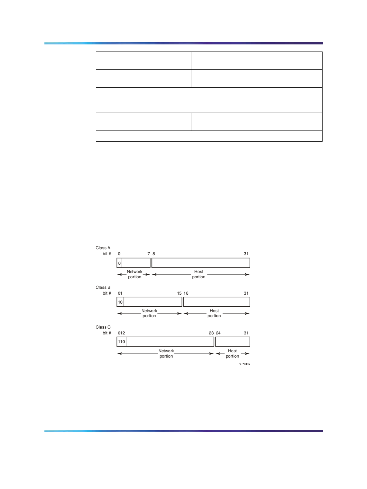
To express an IP address in dotted-decimal notation, each octet of the
IP address is converted to a decimal number and separated by decimal
points. For example, the 32-bit IP address 10000000 00100000 00001010
10100111 is expressed in dotted-decimal notation as 128.32.10.167.
Each IP address class, when expressed in binary notation, has a different
boundary point between the network and host portions of the address, as
illustrated in "Network and host boundaries in IP address classes" (page
14). The network portion is a network number field from 8 through 24 bits.
The remaining 8 through 24 bits identify a specific host on the network.
Network and host boundaries in IP address classes
Subnet addressing
Subnetworks (or subnets) are an extension of the IP addressing scheme.
Subnets allow an organization to use one IP address range for multiple
networks. Subnets are two or more physical networks that share a common
network-identification field (the network portion of the 32-bit IP address).
Copyright © 2005-2007, Nortel Networks
.
Nortel Ethernet Routing Switch 5500 Series
Configuration-IP Routing Protocols
NN47200-503 03.01 Standard
5.1 27 August 2007
Page 15

IP routing 15
A subnet address is created by increasing the network portion to include
a subnet address, thus decreasing the host portion of the IP address. For
example, in the address 128.32.10.0, the network portion is 128.32, while
the subnet is found in the first octet of the host portion (10). A subnet mask
is applied to the IP address and identifies the network and host portions
of the address.
" Subnet masks for Class B and Class C IP addresses" (page 15)illustrates
how subnet masks used with Class B and Class C addresses can create
differing numbers of subnets and hosts. This example shows the use of the
zero subnet, which is permitted on a Nortel Ethernet Routing Switch 5510.
Subnet masks for Class B and Class C IP addresses
Number
of bits
Subnet Mask
Number of Subnets
(Recommended)
Number of Hosts
per Subnet
Class B
2 255.255.192.0 2 16 382
3 255.255.224.0 6 8 190
4 255.255.240.0 14 4 094
5
255.255.248.0 30 2 046
6 255.255.252.0 62 1 022
7
255.255.254.0 126 510
8 255.255.255.0 254 254
9 255.255.255.128 510 126
10 255.255.255.192 1 022 62
11 255.255.255.224 2 046 30
12 255.255.255.240 4 094 14
13 255.255.255.248 8 190 6
14 255.255.255.252 16 382 2
Class C
1 255.255.255.128 0 126
2 255.255.255.192 2 62
3 255.255.255.224 6 30
4 255.255.255.240 14 14
5
6 255.255.255.252 62 2
Copyright © 2005-2007, Nortel Networks
.
255.255.255.248 30 6
Nortel Ethernet Routing Switch 5500 Series
Configuration-IP Routing Protocols
NN47200-503 03.01 Standard
5.1 27 August 2007
Page 16

16 An Introduction to IP Routing Protocols
Variable-length subnet masking (VLSM) is the ability to divide an intranet
into pieces that match network requirements. Routing is based on the
longest subnet mask or network that matches.
IP routing using VLANs
The Nortel Ethernet Routing Switch 5500 Series supports wire-speed IP
routing between virtual LANs (VLAN). This type of routing is also referred to
as virtual routing. When a virtual router interface is created for a specified
VLAN, a specific IP address is associated with the specific VLAN. In this
release, the Nortel Ethernet Routing Switch 5500 Series supports static
routing, in which the identifiers of the devices being routed between are
entered manually.
This virtual router interface does not have an association with any specified
port or set of ports (it is called a virtual router interface because it is not
associated with any particular port). The VLAN IP address can be reached
through any of the ports in the VLAN specified as a virtual router interface,
and the assigned IP address is the gateway through which packets are
routed out of that VLAN. Routed traffic can be forwarded to another VLAN
within the switch or stack of Nortel Ethernet Routing Switch 5500 Series.
Once routing is enabled on two VLANs by assigning IP addresses, routing
can be performed between those two VLANs (refer to "IP routing with
VLANs" (page 16)).
IP routing with VLANs
IP routing is enabled or disabled globally on the Nortel Ethernet Routing
Switch 5500 Series. By default, IP routing is disabled.
Note: All IP routing parameters can be configured on the Nortel
Ethernet Routing Switch 5500 Series before routing is actually enabled
on the switch.
There is no longer a one-to-one correspondence between the physical
port and the router interface, because a given port can belong to multiple
VLANs. The VLANs may be configured for routing on the switch.
Copyright © 2005-2007, Nortel Networks
.
Nortel Ethernet Routing Switch 5500 Series
Configuration-IP Routing Protocols
NN47200-503 03.01 Standard
5.1 27 August 2007
Page 17

IP routing 17
As with any IP address, virtual router interface addresses are also used for
device management. For management over IP, any virtual router interface
IP address can be used to access the switch as long as routing is enabled.
When the Nortel Ethernet Routing Switch 5500 Series switch or stack is
used without routing enabled, the Management VLAN is reachable only
through the switch or stack IP address. With IP routing enabled on the
switch or stack, any of the virtual router IP interfaces can be used for
management over IP.
Once routing is enabled on the Nortel Ethernet Routing Switch 5500 Series
switches, the Management VLAN behaves like all other routable VLANs.
The IP address is reachable through any virtual router interface, as long as
a route is available. Actually, all virtual router interfaces can be used as the
Management VLAN over IP.
Multinetting
The Nortel Ethernet Routing Switch 5500 Series supports the definition
and configuration of up to eight secondary interfaces on each VLAN
(multinetting). With IP multinetting, you can associate multiple IP subnets
with one VLAN. That is, connected hosts can belong to different IP subnets
on the same VLAN.
Multinetting can be configured using the CLI or the Device Manager.
The following diagram illustrates a network with configured IP multinetting.
Copyright © 2005-2007, Nortel Networks
.
Nortel Ethernet Routing Switch 5500 Series
Configuration-IP Routing Protocols
NN47200-503 03.01 Standard
5.1 27 August 2007
Page 18
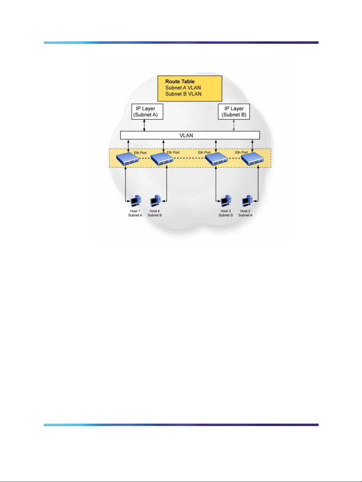
18 An Introduction to IP Routing Protocols
Network with Multinetting
You can configure a static route with the next hop on the secondary
interface. You can also add static ARP for a given IP address in the same
subnet of a secondary interface.
Here are some limitations when you are working with secondary interfaces:
•
you can have a maximum of eight secondary interfaces on each VLAN
•
you can have a total maximum of 256 IP interfaces (including primary
and secondary)
•
all of the secondary interfaces on a VLAN are enabled or disabled
together. There is no provision for configuring the administrative state of
the secondary IP interfaces individually.
•
dynamic routing is not available for secondary IP interfaces
• secondary interfaces are not supported on brouters
•
a primary IP interface must be in place before secondary IP interfaces
can be added; secondary interfaces must be deleted before you can
delete the primary
Copyright © 2005-2007, Nortel Networks
.
Nortel Ethernet Routing Switch 5500 Series
Configuration-IP Routing Protocols
NN47200-503 03.01 Standard
5.1 27 August 2007
Page 19

IP routing 19
If secondary interfaces are configured on the management VLAN, routing
cannot be disabled globally or on the management VLAN. Secondary IP
interfaces on the management VLAN are purged from NVRAM when
•
a unit leaves the stack and the switch does not have a manually
configured IP
•
the switch fails to get the IP address through the BootP mode
The following are not supported on secondary interfaces:
•
DHCRP
•
Proxy ARP
•
UDP broadcast
•
IPFIX
•
VRRP, OSPF, RIP
For information about configuring secondary interfaces on VLANs, see "IP
routing using VLANs" (page 16).
Brouter port
The Nortel Ethernet Routing Switch 5500 Series supports the concept
of brouter ports. A brouter port is a single-port VLAN that can route IP
packets as well as bridge all non-routable traffic. The difference between
a brouter port and a standard IP protocol-based VLAN configured to do
routing is that the routing interface of the brouter port is not subject to
the spanning tree state of the port. A brouter port can be in the blocking
state for non-routable traffic and still be able to route IP traffic. This feature
removes any interruptions caused by Spanning Tree Protocol recalculations
in routed traffic. A brouter port is actually a one-port VLAN; therefore, each
brouter port decreases the number of available VLANs by one and uses
one VLAN ID.
When a brouter port is created, the following actions are also taking place
on the switch:
•
A port-based VLAN is created.
•
The brouter port is added to the new port-based VLAN.
•
The PVID of the brouter port is changed to the VLAN ID of the new
VLAN.
•
The STP participation of the brouter port is disabled.
•
An IP address is assigned to the brouter VLAN.
Copyright © 2005-2007, Nortel Networks
.
Nortel Ethernet Routing Switch 5500 Series
Configuration-IP Routing Protocols
NN47200-503 03.01 Standard
5.1 27 August 2007
Page 20

20 An Introduction to IP Routing Protocols
Management VLAN
Prior to Software Release 4.0, the Management VLAN was the only VLAN
that was used to carry the management traffic, including Telnet, Web,
SNMP, BootP and TFTP for the switch. The Management VLAN always
exists on the switch and cannot be removed. All IP settings, including switch
IP address, stack IP address, subnet mask and default gateway, apply only
to the Management VLAN.
In this release of Nortel Ethernet Routing Switch 5500 Series, a regular
Layer 2 (L2) VLAN behaves like a routable L3 VLAN if a pair of IP addresses
and a MAC address are attached to the VLAN. When routing is enabled in
L3 mode, every L3 VLAN is capable of doing routing as well as carrying the
management traffic. Any L3 VLAN can be used instead of the Management
VLAN to manage the switch.
Layer 2 versus Layer 3 mode
When the Nortel Ethernet Routing Switch 5500 Series is configured to route
IP traffic between different VLANs, the switch is considered to be running in
L3 mode; otherwise, the switch runs in L2 mode.
The L3 manager determines in which mode a switch or a stack should be
run. The mode is determined based on the user settings and events. But
the general rule is to select:
•
L3 mode: if routing is turned on globally for the switch or stack.
•
L2 mode: if routing is turned off globally for the switch or stack.
Routing and management
In L3 mode, the Management VLAN, as well as all other L3 VLANs, has the
capability to route and carry the management traffic. In this release of the
Nortel Ethernet Routing Switch 5500 Series, the settings apply to all L3
VLANs or only to the Management VLAN. "VLAN settings" (page 20)shows
all possible settings and default settings for each type of VLAN.
VLAN settings
VLAN/Feature
Management VLAN
(L2 mode)
Management VLAN
(L3 mode)
L3 VLAN On/off (on) On/off (on) Yes (global)
Setting IP routing
To set IP routing (or L3 VLANs), take the following steps:
Routing
(default)
Off On Yes (Management
On/off (on) On No
Management
(Routing)
Default Route
VLAN only)
Copyright © 2005-2007, Nortel Networks
.
Nortel Ethernet Routing Switch 5500 Series
Configuration-IP Routing Protocols
NN47200-503 03.01 Standard
5.1 27 August 2007
Page 21

Step Action
IP routing 21
1
2
3
Enable IP routing globally.
Assign an IP address to the specific VLAN or brouter port.
Enable IP routing on the interface.
Refer to subsequent chapters in this document for detailed instructions on
configuring IP routes.
Address Resolution Protocol (ARP)
Address Resolution Protocol (ARP)
Network stations using the IP protocol need both a physical address and an
IP address to transmit a packet. If a network station knows only a network
host’s IP address, the Address Resolution Protocol (ARP) enables the
network station to determine a network host’s physical address and bind
the 32-bit IP address to a 48-bit MAC address. A network station can use
ARP across a single network only, and the network hardware must support
physical broadcasts.
If a network station wants to send a packet to a host but knows only the
host’s IP address, the network station uses ARP to determine the host’s
physical address as follows:
—End—
1. The network station broadcasts a special packet, called an ARP request,
that asks thehost at the specified IP address to respond with its physical
address.
2. All network hosts receive the broadcast message.
3. Only the specified host responds with its hardware address.
4. The network station then maps the host’s IP address to its physical
address and saves the results in an address resolution table for future
use.
5. The network station’s ARP table displays the association of the known
MAC addresses to IP addresses.
Note: The default timeout value for ARP entries is 6 hours.
Static ARP entries can be created and individual ARP entries deleted.
Copyright © 2005-2007, Nortel Networks
.
Nortel Ethernet Routing Switch 5500 Series
Configuration-IP Routing Protocols
NN47200-503 03.01 Standard
5.1 27 August 2007
Page 22
22 An Introduction to IP Routing Protocols
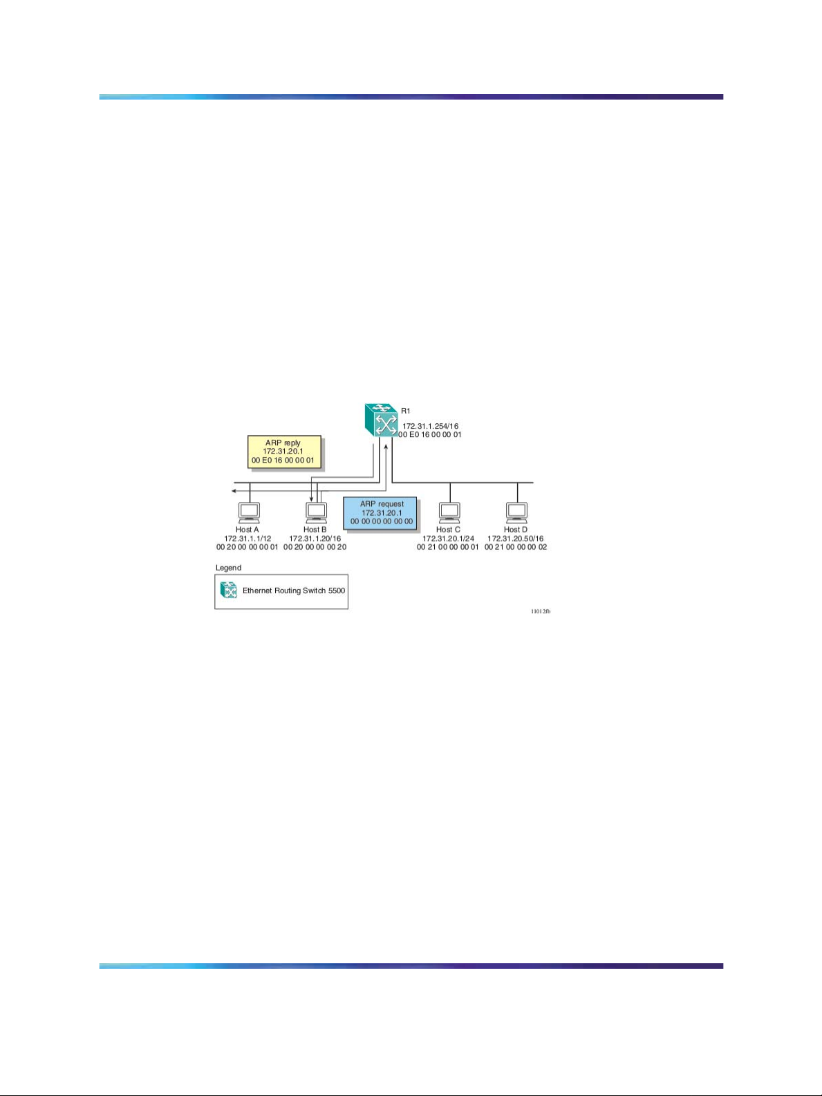
Proxy Address Resolution Protocol (Proxy ARP)
Proxy ARP allows a network station to respond to an ARP request from a
locally attached host or end station for a remote destination. It does so by
sending an ARP response back to the local host with its own MAC address
of the network station interface for the subnet on which the ARP request
was received. The reply is generated only if the switch has an active route
to the destination network.
The figure below is an example of proxy ARP operation. In this example,
host C with a 24-bit mask appears to be locally attached to host B with a
16-bit mask, so host B sends an ARP request for host C. However, the 5500
Series switch is between the two hosts. To enable communication between
the two hosts, the 5500 Series switch would respond to the ARP request
with host C’s IP address but with its own MAC address.
Proxy ARP Operation
Static routes
Once routable VLANs are created though IP address assignment, static
routes can be created. Static routes allow for the manual creation of specific
routes to a destination IP address. Static routes can also be used to specify
a route to all networks for which there are no explicit routes in the Forwarding
Information Base or the routing table. This static default route is a route to
the network address 0.0.0.0 as defined by the IEEE RFC 1812 standard.
Because of their static nature, this type of solution is not scalable. Thus,
in a large or growing network this type of route management may not be
desirable. Also, static routes do not have the capacity to determine the
failure of paths. Thus, a router can still attempt to use a path after it has
failed.
Copyright © 2005-2007, Nortel Networks
.
Nortel Ethernet Routing Switch 5500 Series
Configuration-IP Routing Protocols
NN47200-503 03.01 Standard
5.1 27 August 2007
Page 23

Non-local static routes
The Nortel Ethernet Routing Switch 5500 Series supports the usage of
non-local static routes. A non-local static route is almost identical to a
static route with the exception that the next hop of the route is not directly
connected to the network entity. Non-local static routes are useful in
situations where there are multiple paths to a network and the number
of static routes could be reduced by using only one route with a remote
gateway.
Because of their static nature, this type of solution is not scalable. Thus,
in a large or growing network this type of route management may not
be desirable. Also, non-local static routes do not have the capacity to
determine the failure of paths. Thus, a router can still attempt to use a path
after it has failed.
Routing Information Protocol (RIP)
Routing Information Protocol (RIP) is a standard, dynamic routing protocol
based on the Bellman-Ford (or distance vector) algorithm. It is used as an
Interior Gateway Protocol (IGP). RIP allows routers to exchange information
to compute routes through an IPv4-based network. The hop count, or
distance, is used as a metric to determine the best path to a remote network
or host. The hop count cannot exceed 15 hops (assuming a cost of one
hop for each network).
IP routing 23
RIP is defined in RFC 1058 for RIP version 1 and RFC 2453 for RIP version
2. The most significant difference between the two versions is that RIP
version 2 supports subnet masks and next hop information in the RIP
packet.
RIP operation
RIP uses User Datagram Protocol (UDP) data packets to exchange
routing information. Each router maintains a routing table, which lists the
optimal route to every destination in the system. Each router advertises
its routing information by sending a routing information update at regular
intervals. Neighboring routers use this information to recalculate their
routing tables and retransmit the routing information. For RIP version 1,
no mask information is exchanged; the natural mask is always applied by
the router receiving the update. For RIP version 2, mask information is
always included.
The sequence of processes governed by the routing algorithm is as follows:
1. When a router starts, it initializes the RIP data structures and then waits
for indications from lower-level protocols that its interfaces are functional.
2. RIP advertisements are send on all the interfaces that are configured to
send routing information.
Copyright © 2005-2007, Nortel Networks
.
Nortel Ethernet Routing Switch 5500 Series
Configuration-IP Routing Protocols
NN47200-503 03.01 Standard
5.1 27 August 2007
Page 24

24 An Introduction to IP Routing Protocols
3. The neighbors will send their routing tables and the new router will
update its routing table based on the advertisements received.
4. From now on periodic updates are send by each router in the network to
ensure a correct routing database.
If a router does not receive an update from another router within a timeout
period, it deletes the routes served by the nonupdating router from its
routing table. However, it keeps these routes temporarily in a garbage list
and continues to advertise them with a metric of 16 for a holddown period,
so that neighbors know that the routes are unreachable. If a valid update
for a garbage route is received within the holddown period, the router adds
the route back into its routing table. If no update is received, the router
completely deletes all garbage list entries for the nonupdating router.
To prevent routing loops and to promote fast convergence, RIP uses
the mechanisms of split horizon, with or without poisoned reverse, and
triggered updates. Simple split horizon means that IP routes learned from a
neighbor are not advertised back in updates to that neighbor. Split horizon
with poisoned reverse means that these routes are advertised back to the
neighbor, but they are “poisoned” with a metric of 16, which represents
infinite hops in the network. The receiver neighbor therefore ignores this
route. Triggered updates means that a router is required to send update
messages whenever it changes the metric for a route, even if it is not yet
time for a regular update message.
RIP sends routing information updates every 30 seconds. These updates
contain information about known networks and the distances (hop count)
associated with each. For RIP version 1, no mask information is exchanged;
the natural mask is always applied by the router receiving the update. Mask
information is always included for RIP version 2.
If information about a network is not received for within the allotted timeout
period (180 seconds by default), it is removed from the routing table and the
route is moved to the garbage list . From the garbage list it will be advertised
for the allotted holdown period (120 seconds by default) with metric set to
infinity (16). These timers can be changed by configuring the RIP Interface
Timeout Timer and Holddown Timer parameters.
RIP supports the following standard behavior:
•
periodic RIP updates about effective best routes
•
garbage collection
•
split horizon with or without poisoned reverse
•
triggered update for changed RIP routes
•
unicast to the specific query requestor
•
broadcast/multicast of regular and triggered updates
Copyright © 2005-2007, Nortel Networks
.
Nortel Ethernet Routing Switch 5500 Series
Configuration-IP Routing Protocols
NN47200-503 03.01 Standard
5.1 27 August 2007
Page 25
IP routing 25
•
subnet mask (RIP version 2)
•
routing table update based on the received RIP message
•
global update timer
•
holddown timer and timeout timer per device and per interface
•
cost per device and per interface
The Nortel Ethernet Routing Switch 5500 Series implementation of RIP
also supports the following features:
•
in and out routing policies
•
auto-aggregation (also known as auto-summarization) of groups of
adjacent routes into single entries
Many RIP features are configurable. The actual behavior of the protocol
depends on the feature configurations.
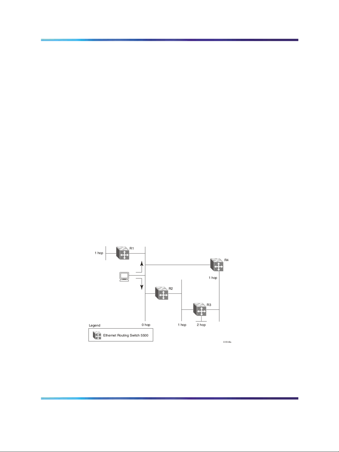
RIP metrics
RIP is known as a distance vector protocol. The vector is the network
number and next hop, and the distance is the cost associated with the
network number. RIP identifies network reachability based on cost, and
cost is defined as hop count. The distance from one router to the next is
considered to be one hop. This cost or hop count is known as the metric The
illustration below depicts the hop counts between various units in a network.
RIP hop counts
A directly connected network has a metric of zero. An unreachable network
has a metric of 16. Therefore, 15 hops or 15 routers is the highest possible
metric between any two networks.
Copyright © 2005-2007, Nortel Networks
.
Nortel Ethernet Routing Switch 5500 Series
Configuration-IP Routing Protocols
NN47200-503 03.01 Standard
5.1 27 August 2007
Page 26

26 An Introduction to IP Routing Protocols
RIP Send and Receive Modes
RIP can be configured to use a number of different send and receive modes
depending on the specifics of the network configuration. The following table
lists the send and receive modes supported.
RIP send and receive modes
Send Mode
Description Result
rip1comp This mode is used to
broadcast RIP version
2 updates using RFC
1058 route consumption
rules. This is the default
send mode for the Nortel
Ethernet Routing Switch
5500 Series.
rip1 This mode is used to
broadcast RIP updates
that are compliant with
RFC 1058.
•
Destination MAC is a broadcast,
ff-ff-ff-ff-ff-ff
•
Destination IP is a broadcast
for the network (for example,
192.1.2.255)
•
RIP Update is formed as a
RIP version 2 update, including
network mask
•
RIP version = 2
• Destination MAC is a broadcast,
ff-ff-ff-ff-ff-ff
• Destination IP is a broadcast
for the network (for example,
192.1.2.255)
•
RIP Update is formed as a RIP
version 1 update, no network
mask included
• RIP version = 1
rip2 This mode is used to
nosend No RIP updates are sent
Receive
Mode
Copyright © 2005-2007, Nortel Networks
.
•
Destination MAC is a multicast,
broadcast multicast RIP
version 2 updates.
01-00-5e-00-00-09
•
Destination IP is the RIP version
2 multicast address, 224.0.0.9
•
RIP Update is formed as a
RIP version 2 update including
network mask
•
RIP version = 2
None
on the interface.
Result
Nortel Ethernet Routing Switch 5500 Series
Configuration-IP Routing Protocols
NN47200-503 03.01 Standard
5.1 27 August 2007
Page 27

rip1OrRip2 RIP version 1 or RIP version 2 updates are accepted.
rip1 RIP version 1 and RIP version 1 compatible updates only are
accepted.
rip2 RIP version 2 updates only are accepted.
Limitations
RIP has the following limitations:
•
The protocol is limited to networks whose longest path is 15 hops.
•
The protocol depends on counting to infinity to resolve certain unusual
situations.
•
The protocol uses fixed metrics (the hop number)to compare alternative
routes, as opposed to real-time parameters such as measured delay,
reliability, or load.
•
RIP does not support address-less links.
Open Shortest Path First (OSPF) protocol
The Open Shortest Path First (OSPF) Protocol is an Interior Gateway
Protocol (IGP) that distributes routing information between routers belonging
to a single autonomous system (AS). Intended for use in large networks,
OSPF is a link-state protocol which supports IP subnetting and the tagging
of externally-derived routing information.
IP routing 27
Note: The Nortel Ethernet Routing Switch 5500 Series implementation
of OSPF only supports broadcast and passive interfaces. Point-to-point
and NBMA interfaces are not supported.
Overview
In an OSPF network, each router maintains a link-state database that
describes the topology of the autonomous system (AS). The database
contains the local state for each router in the AS, including the router’s
usable interfaces and reachable neighbors.
Each router periodically checks for changes in its local state and shares any
changes detected by flooding link-state advertisements (LSAs) throughout
the AS. Routers synchronize their topological databases based on the
sharing of information from LSAs.
From the topological database, each router constructs a shortest-path tree,
with itself as the root. The shortest-path tree gives the optimal route to each
destination in the AS. Routing information from outside the AS appears on
the tree as leaves.
OSPF routes IP traffic based solely on the destination IP address and
subnet mask contained in the IP packet header.
Copyright © 2005-2007, Nortel Networks
.
Nortel Ethernet Routing Switch 5500 Series
Configuration-IP Routing Protocols
NN47200-503 03.01 Standard
5.1 27 August 2007
Page 28

28 An Introduction to IP Routing Protocols
Benefits
Benefits in large networks OSPF offers the following benefits:
•
Fast convergence
In the event of topological changes, OSPF recalculates routes quickly.
•
Minimal routing protocol traffic
Unlike distance vector routing protocols such as RIP, OSPF generates a
minimum of routing protocol traffic.
•
Load sharing
OSPF provides support for equal-cost multipath routing. If several
equal-cost routes to a destination exist, traffic is distributed equally
among them.
•
Because OSPF does not use hop count in its calculation, the routing
domain is scalable.
OSPF routing algorithm
A separate copy of the OSPF routing algorithm runs in each area. Routers
which are connected to multiple areas run multiple copies of the algorithm.
The sequence of processes governed by the routing algorithm is as follows:
1. When a router starts, it initializes the OSPF data structures and then
waits for indications from lower-level protocols that its interfaces are
functional.
2. A router then uses the Hello Protocol to discover neighbors. On
point-to-point and broadcast networks the router dynamically detects
its neighbors by sending hello packets to the multicast address
AllSPFRouters. On non-broadcast multiaccess networks, some
configuration information is required in order to discover neighbors.
3. On all multiaccess networks (broadcast or non-broadcast), the Hello
Protocol also elects a DR for the network.
4. The router attempts to form adjacencies with some of its neighbors.
On multiaccess networks, the DR determines which routers become
adjacent. This behavior does not occur if a router is configured as a
passive interface, because passive interfaces do not form adjacencies.
5. Adjacent neighbors synchronize their topological databases.
6. The router periodically advertises its link-state, and also does so when
its local state changes. LSAs include information about adjacencies
enabling quick detection of dead routers on the network.
7. LSAs are flooded throughout the area, ensuring that all routers in an
area have exactly the same topological database.
Copyright © 2005-2007, Nortel Networks
.
Nortel Ethernet Routing Switch 5500 Series
Configuration-IP Routing Protocols
NN47200-503 03.01 Standard
5.1 27 August 2007
Page 29

IP routing 29
8. From this database each router calculates a shortest-path tree, with
itself as root. This shortest-path tree in turn yields a routing table for
the protocol.
OSPF router types
Routers in an OSPF network can take on different roles depending their
configuration. The following table describes the router types in an OSPF
network.
OSPF router types
Router Type Description
Autonomous System
Boundary Router
(ASBR)
Area Border Router
(ABR)
Internal Router (IR) A router that has interfaces only within a single area
Designated Router
(DR)
Backup Designated
Router (BDR)
A router attached at the edge of an OSPF network
is called an AS boundary router (ASBR). An ASBR
generally has one or more interfaces that run an
inter-domain routing protocol. In addition, any router
distributing static routes or RIP routes into OSPF is
considered an ASBR. The ASBR forwards external
routes into the OSPF domain. In this way, routers inside
the OSPF network learn about destinations outside their
domain.
A router attached to two or more areas inside an OSPF
network is considered an area border router (ABR). ABRs
play an important role in OSPF networks by condensing
the amount of OSPF information that is disseminated.
inside an OSPF network is considered an internal router
(IR). Unlike ABRs, IRs have topological information only
about the area in which they are contained.
In a broadcast network a single router is elected to
be the designated router (DR) for that network. A DR
assumes the responsibility of making sure all routers on
the network are synchronized with one another and also
advertises that network to the rest of the AS.
A backup designated router (BDR) is elected in addition
to the designated router (DR) and, in the event of failure
of the DR, will assume its role quickly.
OSPF host route
An OSPF router with hosts directly attached to its interfaces can use host
routes to advertise the attached hosts to its neighbors. You can configure
up to 32 host routes.
Copyright © 2005-2007, Nortel Networks
.
Nortel Ethernet Routing Switch 5500 Series
Configuration-IP Routing Protocols
NN47200-503 03.01 Standard
5.1 27 August 2007
Page 30

30 An Introduction to IP Routing Protocols
Host routes are managed with Nortel Networks Command Line Interface
(NNCLI) commands and SNMP MIBs and are identified by the host IP
address and the configured route type of service (TOS). For each host
directly connected to the router, configure the cost of the link to the host
during host creation. You cannot modify this cost.
Note: Always set TOS to 0 because TOS-based routing is not
supported.
When a host is added to, or deleted from, a host route, the router updates
the router LSAs and floods them to neighbors in each area where that
router has an interface.
Followingis an exampleof parameters fora host route advertised in the LSA.
Host route in LSA
•
Type: 3 (stub network)
•
LinkID: IP address of host directly connected to router
•
Link Data: 0xFFFFFFFF
•
Metric: configured cost of host
OSPF Enhancements
•
Host route - Allows a router to advertise to its neighbors all hosts that
are directly attached to that router’s interfaces. Up to 32 host routes
can be configured.
•
Virtual links - The OSPF network can be partitioned into multiple
areas. However, a backbone area must exist and be contiguous, and
every non-backbone area must be connected to the backbone area
using either a physical or a logical link. In a network where a physical
connection between the non-backbone area and backbone area is
impossible, use of a virtual link provides the logical connection through
another non-backbone area, called the transit area. Virtual links can be
created manually or automatically. The 5500 Series switch supports
up to 16 virtual links.
When 5500 Series switches are stacked, and a unit leaves the stack and
becomes standalone, the router ID is automatically changed to its default
value if IP blocking is turned off and OSPF is globally enabled. This
prevents duplication of a router ID in the OSPF routing domain. The new
router ID value is temporary, that is, it is not saved to NVRAM. Therefore,
upon reset, the old router ID is restored. Configurable using NNCLI, ACG,
and Device Manager.
Example configurations The following is an example for creating a host
route:
Copyright © 2005-2007, Nortel Networks
.
Nortel Ethernet Routing Switch 5500 Series
Configuration-IP Routing Protocols
NN47200-503 03.01 Standard
5.1 27 August 2007
Page 31

Creating Host Route
Example : 1
R3(config)#router ospf
R3(config-router)#host-route 11.11.11.111 metric 10
R3(config-router)#show ip ospf host-route
Host IP Metric
11.11.11.111 10
R3(config-router)#
The following is an example for deleting a host route:
Deleting Host Route
Example : 1
R3(config-router)#no host-route 11.11.11.111
R3(config-router)#show ip ospf host-route
Host IP Metric
IP routing 31
R3(config-router)#
OSPF virtual link
On an OSPF network, a router acting as an area boundary router (ABR)
must be directly connected to the backbone. If no physical connection is
available, you can create a virtual link.
A virtual link is established between two endpoint ABRs and is a logical
connection to the backbone area through a non-backbone area called a
transit area. In the following diagram, non-backbone ABR 2 establishes a
virtual link with backbone ABR1 across transition area, area 1. The virtual
link connects area 2 to area 0.
Copyright © 2005-2007, Nortel Networks
.
Nortel Ethernet Routing Switch 5500 Series
Configuration-IP Routing Protocols
NN47200-503 03.01 Standard
5.1 27 August 2007
Page 32

32 An Introduction to IP Routing Protocols
Virtual link diagram
Note: Stub or NSSA areas cannot be transit areas.
A virtual link can be created manually or automatically.
Manual virtual link creation can conserve resources and provide specific
control of virtual link placement in the OSPF configuration.
To add a virtual link manually, configure both endpoint ABRs with a neighbor
router ID and transit area ID. You can configure up to 16 virtual links.
Note: You can modify parameters for manually added virtual links.
To accept automatic virtual link creation, enable automatic virtual link on
both endpoint ABRs (the default value is disabled). Automatic virtual links
are removed when the transit area is deleted, auto virtual link is disabled,
or the router is no longer an ABR.
Note: Auto-created virtual links use default settings that cannot be
modified.
Example Configuration
Consider the following situation:
Copyright © 2005-2007, Nortel Networks
.
Nortel Ethernet Routing Switch 5500 Series
Configuration-IP Routing Protocols
NN47200-503 03.01 Standard
5.1 27 August 2007
Page 33

IP routing 33
In this case, R4 in Area2 cannot be physically connected to Area0 (for some
reason) and it will be connected to R3 which is NOT a backbone ABR (like
R1 is for instance). As Area2 is not directly connected to backboneArea0 or
directly connected to a backbone ABR router, clients from Area2 will not be
able to access anything outside Area2. Also, router R3 is an ABR router
connected to two non-backbone areas.
In order to solve these problems, virtual-link must be configured between
router R3 and R1 which are both ABRs. Virtual-link cannot be configured
on non-ABR routers.
Consider the following Router IDs:
•
R1 : 1.0.0.0
•
R3 : 3.0.1.0
•
R4 : 4.0.2.0
Virtual-link can be configured in two ways on ABR routers :
•
Configuring virtual link manually
•
Configuring virtual link automatically
The following is an example for creating an auto virtual link:
Creating auto virtual link
R1 (config-router)#auto-vlink
Example : 1
R1(config)#show ip ospf
Router ID: 1.0.0.0
Admin Status: Enabled
Version Number: 2
Area Border Router Oper Status: True
AS Boundary Router Config Status: False
External Link-State Advertisements: 0
External Link-State Checksum: 0(0x0)
Type-of-Service (TOS) Routing Supported: False
Originated Link-State Advertisements: 67
New Link-State Advertisements Received: 722
Copyright © 2005-2007, Nortel Networks
.
Nortel Ethernet Routing Switch 5500 Series
Configuration-IP Routing Protocols
NN47200-503 03.01 Standard
5.1 27 August 2007
Page 34

34 An Introduction to IP Routing Protocols
OSPF Traps: Disabled
Auto Virtual Link Creation: Enabled
SPF Hold-Down Time: 10
RFC 1583 Compatibility: Enabled
R3 (config-router)#auto-vlink
Example : 2
R3(config)#show ip ospf
Router ID: 3.0.1.0
Admin Status: Enabled
Version Number: 2
Area Border Router Oper Status: True
AS Boundary Router Config Status: False
External Link-State Advertisements: 0
External Link-State Checksum: 0(0x0)
Type-of-Service (TOS) Routing Supported: False
Originated Link-State Advertisements: 67
New Link-State Advertisements Received: 722
OSPF Traps: Disabled
Auto Virtual Link Creation: Enabled
SPF Hold-Down Time: 10
RFC 1583 Compatibility: Enabled
The following is an example for deleting an auto virtual link:
Deleting auto virtual link
R1 (config-router)#no auto-vlink
Example : 1
R1(config)#show ip ospf
Router ID: 1.0.0.0
Admin Status: Enabled
Version Number: 2
Area Border Router Oper Status: True
AS Boundary Router Config Status: False
External Link-State Advertisements: 0
External Link-State Checksum: 0(0x0)
Type-of-Service (TOS) Routing Supported: False
Originated Link-State Advertisements: 67
New Link-State Advertisements Received: 722
OSPF Traps: Disabled
Auto Virtual Link Creation: Disabled
SPF Hold-Down Time: 10
RFC 1583 Compatibility: Enabled
R3 (config-router)#no auto-vlink
Example : 2
R3(config)#show ip ospf
Copyright © 2005-2007, Nortel Networks
.
Nortel Ethernet Routing Switch 5500 Series
Configuration-IP Routing Protocols
NN47200-503 03.01 Standard
5.1 27 August 2007
Page 35

Router ID: 3.0.1.0
Admin Status: Enabled
Version Number: 2
Area Border Router Oper Status: True
AS Boundary Router Config Status: False
External Link-State Advertisements: 0
External Link-State Checksum: 0(0x0)
Type-of-Service (TOS) Routing Supported: False
Originated Link-State Advertisements: 67
New Link-State Advertisements Received: 722
OSPF Traps: Disabled
Auto Virtual Link Creation: Disabled
SPF Hold-Down Time: 10
RFC 1583 Compatibility: Enabled
Virtual-Link can also be configured using the Java Device Manager (JDM).
Just go under IP Routing > OSPF menu. There you can find : ‘General’ tab
for Auto-Vlink creation, ‘Virtual If’ tab, and ‘Virtual Neighbors’ tab.
Route policies
Route policies are a Nortel proprietary improvement on existing routing
schemes. Using existing routing schemes, packets are forwarded based
on routes that have been learned by the router through routing protocols
such as RIP and OSPF or through the introduction of static routes. Route
policies introduce the ability to forward packets based on rule sets created
by the network administrator. These rule sets, or policies, are then applied
to the learned or static routes.
IP routing 35
Route policies on the Nortel Ethernet Routing Switch 5500 Series supports
the Routing Information Protocol (RIP) and Open Shortest Path First
(OSPF) protocol. When used in conjunction with these protocols, route
policies can be used to perform the following tasks that are not possible
using traditional routing methods:
•
Listen for routing updates from specific gateways.
•
Listen for routing updates from specific networks.
•
Assign a specific subnet mask to be included with a network in the
routing table.
•
Advertise routing updates from specific gateways.
•
Advertise routing updates to specific networks.
•
Assign a specific subnet mask to be included in the route summary
packets.
•
Advertise routes learned by one protocol to another.
Copyright © 2005-2007, Nortel Networks
.
Nortel Ethernet Routing Switch 5500 Series
Configuration-IP Routing Protocols
NN47200-503 03.01 Standard
5.1 27 August 2007
Page 36

36 An Introduction to IP Routing Protocols
Route policies supports the following types of policies:
• Accept (In) Policies
Accept polices are applied to incoming routing updates before they are
applied to the routing table. In the case of RIP, accept policies can be
applied to all incoming packets and only one policy can be created
for each RIP interface. In the case of OSPF, accept policies are only
applied to Type 5 External routes based on the advertising router ID.
There can only be one OSPF accept policy per switch and the policy
is applied before updates are added to the routing table from the link
state database.
• Announce (Out) Policies
Announce policies are applied to outgoing routing updates before
the routing update packets are actually transmitted from the switch.
In the case of RIP, announce policies can be applied to all outgoing
packets and only one policy can be created for each RIP interface.
Announce policies are not supported for OSPF as OSPF requires
routing information to be consistent throughout the OSPF domain.
• Redistribution Policies
Redistribution policies are used to provide notification of addition or
deletion of a route in the routing table by one protocol to another
protocol. OSPF redistribution policies send redistributed routes as Type
5 External routes. There can be only one OSPF redistribution route per
switch and it must be configured as a ASBR with redistribution enabled.
Route policies consist of the following items:
• Prefix Lists
— List of IP addresses with subnet masks.
— Identified by a prefix list name and unique identifier.
— Prefix lists support the comparison of ranges of incoming masks.
• Route Maps
— Contain a set of match and set parameters.
— Match and set parameters can contain several prefix lists.
— A set of match and set parameters are identified by a sequence
number.
— Accept and deny actions are associated with each sequenced
parameter set.
— Sequence numbers act as a preference setting. Sets with a lower
sequence number are preferred over those with a higher sequence
number.
Copyright © 2005-2007, Nortel Networks
.
Nortel Ethernet Routing Switch 5500 Series
Configuration-IP Routing Protocols
NN47200-503 03.01 Standard
5.1 27 August 2007
Page 37

To configure routing policies, create the appropriate prefix lists and then
assign those prefix lists to route maps. Once all route maps have been
created, assign them to the appropriate type of policy.
In a stacked environment, the following rules are applied to routing policies:
•
The policy database is stored in all stack units.
•
Policy configuration is supported from only the base unit. The base
unit sends updates to non-base units to update the policy database in
each stack unit.
•
During database updates, only the database in the base unit is
synchronized with the non-base unit. The database in the non-base
units are deleted during the exchange.
•
Only the policies stored in the base unit are used by RIP and OSPF
for policy application.
Virtual Router Redundancy Protocol (VRRP)
The Virtual Router Redundancy Protocol (VRRP) is designed to eliminate
the single point of failure that can occur when the single static default
gateway router for an end station is lost. VRRP introduces the concept of
a virtual IP address (transparent to users) shared between two or more
routers connecting a common subnet to the enterprise network. With the
virtual IP address as the default gateway on end hosts, VRRP provides
dynamic default gateway redundancy in the event of failure.
IP routing 37
VRRP uses the following terms:
• VRRP router - a router running the VRRP protocol.
•
Virtual router - the abstract object managed by VRRP that is assigned
the virtual IP address and that acts as the default router for a set of IP
addresses across a common network. Each virtual router is assigned a
virtual router ID.
•
Virtual router master - the VRRP router that assumes responsibility
for forwarding packets sent to the IP address associated with the virtual
router. The master router also responds to packets sent to the virtual
router IP address and answers ARP requests for this IP address.
•
Virtual router backup - the router or routers that can serve as the
failover router if the master router becomes unavailable. If the master
router fails, an election process provides a dynamic transition of
forwarding responsibility to a new master router.
• Priority - an 8-bit value assigned to all VRRP routers. A higher value
represents a higher priority for election to the master router. The priority
can be a value from 1 to 255. When a master router fails, an election
process takes place among the backup routers to dynamically reassign
the role of the master router.
Copyright © 2005-2007, Nortel Networks
.
Nortel Ethernet Routing Switch 5500 Series
Configuration-IP Routing Protocols
NN47200-503 03.01 Standard
5.1 27 August 2007
Page 38

38 An Introduction to IP Routing Protocols
Equal Cost MultiPath (ECMP)
The Equal Cost MultiPath (ECMP) feature allows routers to determine equal
cost paths to the same destination prefix. The multiple paths can be used
for load sharing of traffic and allows faster convergence to other active paths
in case of network failure. By maximizing load sharing among equal-cost
paths, links between routers can be used more efficiently when sending
IP traffic. The ECMP feature supports and complements the following
protocols types:
•
Open Shortest Path First (OSPF)
•
Routing Information Protocol (RIP)
•
Static Routes
ECMP is only supported on the Nortel Ethernet Routing Switch 5520 and
5530. ECMP will work in a mixed stack but will not run on any Nortel
Ethernet Routing Switch 5510 units in the stack.
UDP broadcast forwarding
Some network applications, such as the NetBIOS name service, rely
on User Datagram Protocol (UDP) broadcasts to request a service or
locate a application. If a host is on a network, subnet segment, or VLAN
that includes a server for the service, UDP broadcasts are by default not
forwarded to the server located on a different network segment or VLAN.
This is resolved by forwarding the broadcasts to the server through physical
or virtual interfaces.
UDP broadcast forwarding is a general mechanism for selectively forwarding
limited UDP broadcasts received on an IP interface to a configured IP
address. The packet is sent as a unicast packet to the server.
The following are the basic steps for UDP broadcast forwarding
configuration:
1. Enter the UDP protocols to be forwarded.
2. Create forwarding policies by defining UDP protocol and server pairs.
3. Assemble these policies into lists.
4. Apply these lists to the appropriate interfaces.
When a UDP broadcast is received on a router interface, it must meet the
following criteria if it is to be considered for forwarding:
•
It must be a MAC-level broadcast.
•
It must be an IP-limited broadcast.
•
It must be for a configured UDP protocol.
•
It must have a TTL value of at least 2.
Copyright © 2005-2007, Nortel Networks
.
Nortel Ethernet Routing Switch 5500 Series
Configuration-IP Routing Protocols
NN47200-503 03.01 Standard
5.1 27 August 2007
Page 39

IP routing 39
For each ingress interface and protocol, the UDP broadcast packets are
forwarded only to a unicast host address (the unicast IP address of the
server for example).
Dynamic Host Configuration Protocol (DHCP) / Bootstrap Protocol
(BootP)
DHCP-BootP relay
The Dynamic Host Configuration Protocol (DHCP) is an extension of the
Bootstrap protocol (BootP) and provides host configuration information to
workstations on a dynamic basis. To lower administrative overhead, network
managers prefer to configure a small number of DHCP servers in a central
location. It is necessary for routers to support the BootP/DHCP relay
function so that hosts can access configuration information from servers
several router hops away.
Differences between DHCP and BootP
The following differences between DHCP and BootP are specified in RFC
2131 and include functions that BootP does not address:
•
The Nortel Ethernet Routing Switch 5500 Series supports the Bootstrap
protocol (BootP). BootP enables the retrieval of an ASCII configuration
file name and configuration server address.
•
A properly configured BootP server enables the switch to automatically
learn its assigned IP address, subnet mask and the IP address of the
default router (default gateway).
•
DHCP defines mechanisms through which clients can be assigned a
network address for a finite lease (allowing for reuse of IP addresses).
•
DHCP provides the mechanism for clients to acquire all of the IP
configuration parameters needed to operate.
DHCP uses the BootP message format defined in RFC 951. The remainder
of the options field consists of a list of tagged parameters that are called
"options" (RFC 2131).
Summary of DHCP relay operation
BootP/DHCP clients (workstations) generally use UDP/IP broadcasts to
determine their IP addresses and configuration information. If such a host
is on a network or a subnet segment (or VLAN) that does not include a
DHCP server, the UDP broadcasts are by default not forwarded to the
server located on a different network segment or VLAN. The Nortel Ethernet
Routing Switch 5500 Series can be configured to resolve this issue by
forwarding the broadcasts to the server. The router interfaces can be
configured to forward DHCP broadcasts to other locally connected network
segments or directly to the server’s IP address. DHCP must be enabled
on a per-VLAN basis.
Copyright © 2005-2007, Nortel Networks
.
Nortel Ethernet Routing Switch 5500 Series
Configuration-IP Routing Protocols
NN47200-503 03.01 Standard
5.1 27 August 2007
Page 40

40 An Introduction to IP Routing Protocols
"DHCP operation" (page 40)Figure DHCP operation shows an end station
connected to subnet 1, corresponding to VLAN 1. The Nortel Ethernet
Routing Switch 5500 Series connects two subnets by means of the virtual
routing function. When the end station generates a DHCP request as a
limited UDP broadcast to the IP address of all 1s (that is, 255.255.255.255)
with the DHCP relay function configured, the Nortel Ethernet Routing Switch
5500 Series forwards DHCP requests to subnet 2 or to the host address of
the DHCP server, depending on the configuration.
DHCP operation
Forwarding DHCP packets
In the example shown in "Forwarding DHCP packets" (page 40), the agent
address is 10.10.1.254. To configure the Nortel Ethernet Routing Switch
5500 Series to forward DHCP packets from the end station to the server,
use 10.10.2.1 as the server address.
Forwarding DHCP packets
All BootP broadcast packets, including DHCP packets that appear on the
VLAN 1 router interface (10.10.1.254), will be forwarded to the DHCP
server. In this case, the DHCP packets are forwarded as unicast to the
DHCP server’s IP address.
Multiple BootP-DHCP servers
Most enterprise networks use multiple BootP/DHCP servers for fault
tolerance. The Nortel Ethernet Routing Switch 5500 Series allows switch
configuration to forward BootP/DHCP requests to multiple servers. Up to 10
servers can be configured to receive copies of the forwarded BootP/DHCP
messages.
Copyright © 2005-2007, Nortel Networks
.
Nortel Ethernet Routing Switch 5500 Series
Configuration-IP Routing Protocols
NN47200-503 03.01 Standard
5.1 27 August 2007
Page 41

IP routing 41
If a DHCP client is connected to a routable interface, to configure DHCP
requests to be sent to up to 512 different routable interfaces or 512 different
server IP addresses, enable DHCP on the client (agent address) and then
enable DHCP from the client to each of the interfaces or IP addresses
(server addresses).
In the example shown in "Multiple BootP/DHCP servers" (page 41),two
DHCP servers are located on two different subnets. To configure the
Nortel Ethernet Routing Switch 5500 Series to forward the copies of the
BootP/DHCP packets from the end station to both servers, specify the switch
(10.10.1.254) as the agent address. Then enable DHCP to each of the
DHCP servers by entering 10.10.2.1 and 10.10.3.1 as the server addresses.
Multiple BootP/DHCP servers
Setting DHCP
To set DHCP, take the following steps:
Step Action
1 EnableIP routing on the Nortel Ethernet Routing Switch 5500 Series
and on the target VLAN interface.
2
3
4
5
6
Enable DHCP globally.
Note: DHCP is enabled by default.
Set the DHCP forwarding paths, using the VLAN IP as the starting
point, or agent IP.
Set the mode for each DHCP forwarding path.
Enable DHCP for the specific VLAN.
Enable the DHCP broadcast message for the specific VLAN.
—End—
Copyright © 2005-2007, Nortel Networks
.
Nortel Ethernet Routing Switch 5500 Series
Configuration-IP Routing Protocols
NN47200-503 03.01 Standard
5.1 27 August 2007
Page 42

42 An Introduction to IP Routing Protocols
Any of the Nortel Ethernet Routing Switch 5500 Series switch management
systems can be used to set DHCP.
DHCP relay
DHCP (Dynamic Host Configuration Protocol) is a mechanism to assign
network IP addresses to clients who request an address. It is built on top
of the existing BOOTP protocol and can be specified for DHCP, BOOTP,
or both.
The DHCP relay feature relays client requests to DHCP servers on different
L3 VLANs. It also relays server replies back to the clients.
DHCP relay can be configured through Command Line Interface or Java
Device Manager. DHCP can only be configured on the base unit from
CLI, like all L3 commands. There are three parts in the DHCP relay
configurations. They are:
•
global DHCP enable/disable
• interface configurations
•
forward path configurations
To relay DHCP messages, two VLANs must be created and IP addresses
assigned to them. The client and server must reside on different L3 VLANS
to use DHCP relay. IP routing and global DHCP relay must be enabled
on both the client as well as server.
Note: The DHCP Relay feature shares resources with QoS. If the
DHCP Relay feature is enabled, a QoS policy with a precedence of 11
cannot be installed.
For further information on QoS policies refer to Nortel Ethernet Routing
Switch 5500 Series Configuration - Quality of Service (Part Number
NN47200-504).
Global DHCP relay configuration This configuration enables or disables
DHCP relay for the entire unit or stack. Once DHCP relay is disabled, the
switch/stack will not relay DHCP/BOOTP " Global DHCP relay commands"
(page 42)across L3 VLANs. However, the settings will still be configurable.
describes the global DHCP relay commands.
Global DHCP relay commands
Command
show ip dhcp-relay shows global DHCP relay state
Description
no ip dhcp-relay disables DHCP relay globally
ip dhcp-relay enables DHCP relay globally
Copyright © 2005-2007, Nortel Networks
.
Nortel Ethernet Routing Switch 5500 Series
Configuration-IP Routing Protocols
NN47200-503 03.01 Standard
5.1 27 August 2007
Page 43

IP routing 43
These commands must be executed in the Global Configuration command
mode.
Interface DHCP relay configurations These configurations are
associated with the L3 VLAN that the client or server resides on. IP routing
must be enabled and a valid IP address must be assigned to the L3 VLAN
before it generates the default settings for DHCP relay.
"Interface DHCP relay commands" (page 43)describes the interface DHCP
relay commands. To change the interface DHCP relay configurations, switch
to the Interface Configuration command mode.
Interface DHCP relay commands
Command
show vlan dhcp-relay shows vlan dhcp relay state
ip dhcp-relay min-sec 30 sets min-sec to 30
ip dhcp-relay mode dhcp sets mode to dhcp
no ip dhcp-relay disables ip dhcp-relay
ip dhcp-relay broadcast enables broadcast for this interface
Description
DHCP Relay forward path configurations These configurations are
made per interface IP address and server IP address. " DHCP relay forward
path commands" (page 43)DHCP relay forward path commands table
describes the ip dhcp relay fwd-path commands.
DHCP relay forward path commands
Command
show ip dhcp-relay fwd-path Shows ip dhcp-relay fwd-path.
ip dhcp-relay fwd-path
<agent IP> <server IP>
mode bootp-dhcp
ip dhcp-relay fwd-path
<agent IP> <server IP>
disable
Description
Creates interface IP and server IP path with
modes DHCP & BootP.
Disables the interface/server pair, enable =
false.
no dhcp-relay fwd-path
<agent IP> <server IP>
no ip dhcp-relay Disables ip dhcp-relay.
ip dhcp-relay broadcast Enables broadcast for this interface.
Copyright © 2005-2007, Nortel Networks
.
Deletes the interface/server pair.
Nortel Ethernet Routing Switch 5500 Series
Configuration-IP Routing Protocols
NN47200-503 03.01 Standard
5.1 27 August 2007
Page 44

44 An Introduction to IP Routing Protocols
DHCP relay uses a hardware resource that is shared by switch Quality of
Service applications. When DHCP relay is enabled globally, the Quality
of Service filter manager will not be able to use precedence 11 for
configurations. For the filter manager to be able to use this resource, DHCP
relay must be disabled for the entire unit or stack.
Avoiding duplicate IP addresses
The Nortel Ethernet Routing Switch 5500 Series has built-in safeguards to
avoid issuing duplicate IP addresses, because the switch functions as a
stack as well as a stand-alone system. These safeguards apply to stack
configuration changes (for example, when a stack is forming or after a unit
is removed from a stack).
The system allows the use of an existing IP address under the following
conditions:
•
When a unit leaves a stack:
— If the unit was the acting Base Unit (BU) of the stack and the stack
consisted of only two units.
— If the IP blocking mode in the stack was set to none.
•
When a unit boots up:
— If the unit was never in a stack.
— If IP blocking was manually turned off prior to the current boot.
— If the unit was the designated Base Unit (BU); that is, selected by
hardware switch on the unit, either on the back or on the UI button
on the front; and the stack consisted of only two units.
— If the IP blocking mode was set to none.
If the desired switch IP address is blocked by the system, then the address
must be configured manually in the command line interface.
Automatic router ID change
If a unit leaves the stack and becomes standalone (when the stack disjoins),
the router ID is automatically changed to its default value. This prevents
router ID duplication in the OSPF routing domain.
Prerequisites: IP blocking must be turned off (set to none) and OSPF
must be globally enabled.
TIP: The change in router ID is temporary (not saved in non-volatile random
access memory) and, upon reset, the router ID is restored.
Copyright © 2005-2007, Nortel Networks
.
Nortel Ethernet Routing Switch 5500 Series
Configuration-IP Routing Protocols
NN47200-503 03.01 Standard
5.1 27 August 2007
Page 45

IP blocking
IP Blocking is a Layer 3 feature of the Nortel Ethernet Routing Switch
5500 Series that provides built-in safeguards for the usage of duplicate IP
addresses in a stacked environment. IP Blocking is used whenever a unit
leaves a stack or is rebooting inside the context of a stack. Depending on
the setting in use, Layer 3 functionality is either continued or blocked by
this feature.
IP Blocking can exist in either a none or full condition. When IP Blocking
is set to none, duplicate IP addresses are permitted in the stack
unconditionally. When the full condition is set, duplicate IP addresses are
blocked in the stack unconditionally.
In a stack environment, Nortel recommends that IP blocking mode none be
used in a stack of 2 units. In such a stack environment and IP blocking
mode combination, the following functional characteristics can be expected:
•
IP routing 45
If the stack base unit becomes non-operational the following will occur:
— Layer 3 functionality will continue to run on the non-base unit.
— Dynamic routing protocols still run on the non-base unit.
•
If the stack non-base unit becomes non-operational the following will
occur:
— Layer 3 functionality will continue to run on the base unit.
— Dynamic routing protocols run on the base unit.
A disadvantage of this configuration is that if the non-operational unit does
not rejoin the stack, address duplication will occur.
In stack environments of more than 2 units, Nortel recommends using IP
blocking mode full. In such a stack environment and IP blocking mode
combination, the following functional characteristics can be expected:
• If the stack base unit becomes non-operational the following will occur:
— The temporary base unit takes over base unit duties.
— The temporary base unit runs the Layer 3 and DRP functionality.
— The takeover of the temporary base unit will cause the MAC
addresses of the Layer 3 interfaces to change and the MAC
addresses from the temporary base unit MAC address pool are
used. This may cause a minor disruption in routing traffic. To
facilitate quick failoverin this instance, gratuitous ARP messages are
sent out for each interface for 5 minutes at 15 second intervals.
•
If a stack non-base unit becomes non-operational the following will
occur:
Copyright © 2005-2007, Nortel Networks
.
Nortel Ethernet Routing Switch 5500 Series
Configuration-IP Routing Protocols
NN47200-503 03.01 Standard
5.1 27 August 2007
Page 46

46 An Introduction to IP Routing Protocols
— The stack will continue to run normally with the base unit controlling
Layer 3 and DRP functionality.
— If the non-operational non-base unit does not rejoin the stack, no
Layer 3 or DRP functionality will run on it.
IGMP snooping
The Nortel Ethernet Routing Switch 5500 Series can sense Internet Group
Management Protocol (IGMP) host membership reports from attached
stations and use this information to set up a dedicated path between the
requesting station and a local IP Multicast router. After the pathway is
established, the Nortel Ethernet Routing Switch 5500 Series switch blocks
the IP Multicast stream from exiting any other port that does not connect to
another host member, thus conserving bandwidth. The following section
describes how Nortel Ethernet Routing Switch 5500 Series switches provide
the same benefit as IP Multicast routers, but in the local area.
IGMP is used by IP Multicast routers to learn about the existence of host
group members on their directly attached subnets (see RFC 2236). The IP
Multicast routers get this information by broadcasting IGMP queries and
listening for IP hosts reporting their host group memberships. This process
is used to set up a client/server relationship between an IP Multicast source
that provides the data streams and the clients that want to receive the data.
By default, unknown multicast traffic is flooded to all ports in a VLAN. In
situations in which there is a multicast transmitter that is not doing IGMP
and there are no multicast receivers, the traffic transmitted by the transmitter
is flooded.
The CLI commands for IGMP allow the sending of all unknown multicast
traffic to IGMP static router ports only. This traffic will not be forwarded to
dynamically discovered m-router ports. If it is desirable to forward unknown
unicast traffic to certain ports only, those ports can be set as static m-router
ports.
• When disabled, the Nortel Ethernet Routing Switch 5500 Series switch
treats unknown multicast traffic as it does broadcast traffic (flood). This
is the default behavior.
•
User settings for the Unknown Multicast No Flood feature is stored in
NVRAM. In a stack, if settings on different units differ, the Base Unit
setting will take precedence. This feature can be enabled or disabled
at any time.
•
Nortel Networks recommends this feature be enabled when IGMP
snooping is enabled.
Copyright © 2005-2007, Nortel Networks
.
Nortel Ethernet Routing Switch 5500 Series
Configuration-IP Routing Protocols
NN47200-503 03.01 Standard
5.1 27 August 2007
Page 47

IGMP snooping 47
"IP multicast propagation with IGMP routing" (page 47)shows how IGMP
is used to set up the path between the client and server. As shown in this
example, the IGMP host provides an IP Multicast stream to designated
routers that forward the IP Multicast stream on their local network only
if there is a recipient.
The client/server path is set up as follows:
1. The designated router sends out a host membership query to the subnet
and receives host membership reports from end stations on the subnet.
2. The designated routers then set up a path between the IP Multicast
stream source and the end stations.
3. Periodically, the router continues to query end stations about whether
to continue participation.
4. As long as any client continues to participate, all clients, including
non-participating end stations on that subnet, receive the IP Multicast
stream.
Note: Although the non-participating end stations can filter the IP
Multicast traffic, the IP Multicast traffic still exists on the subnet and
consumes bandwidth.
IP Multicast can be optimized in a LAN by using IP Multicast filtering
switches, such as the Nortel Ethernet Routing Switch 5500 Series.
As shown in "IP multicast propagation with IGMP routing" (page 47),a
non-IP Multicast filtering switch causes IP Multicast traffic to be sent to
all segments on the local subnet.
IP multicast propagation with IGMP routing
Copyright © 2005-2007, Nortel Networks
.
Nortel Ethernet Routing Switch 5500 Series
Configuration-IP Routing Protocols
NN47200-503 03.01 Standard
5.1 27 August 2007
Page 48

48 An Introduction to IP Routing Protocols
The Nortel Ethernet Routing Switch 5500 Series can automatically set up IP
Multicast filters so the IP Multicast traffic is only directed to the participating
end nodes (see ).
In , "5500 Series switch filtering IP multicast streams (1 of 2)" (page
48)switches S1 to S4 represent a LAN connected to an IP Multicast router.
The router periodically sends Host Membership Queries to the LAN and
listens for a response from end stations. All of the clients connected to
switches S1 to S4 are aware of the queries from the router.
One client, connected to S2, responds with a host membership report.
Switch S2 intercepts the report from that port, and generates a proxy report
to its upstream neighbor, S1. Also, two clients connected to S4 respond
with host membership reports, causing S4 to intercept the reports and to
generate a consolidated proxy report to its upstream neighbor, S1.
5500 Series switch filtering IP multicast streams (1 of 2)
Switch S1 treats the consolidated proxy reports from S2 and S4 as if
they were reports from any client connected to its ports, and generates a
consolidated proxy report to the designated router. In this way, the router
receives a single consolidated report from that entire subnet.
After the switches learn which ports are requesting access to the IP
Multicast stream, all other ports not responding to the queries are blocked
from receiving the IP Multicast ("5500 Series switch filtering IP multicast
streams (2 of 2)" (page 49)).
Copyright © 2005-2007, Nortel Networks
.
Nortel Ethernet Routing Switch 5500 Series
Configuration-IP Routing Protocols
NN47200-503 03.01 Standard
5.1 27 August 2007
Page 49

IGMP snooping 49
5500 Series switch filtering IP multicast streams (2 of 2)
The consolidated proxy report generated by the switch remains transparent
to Layer 3 of the International Standardization Organization, Open Systems
Interconnection (ISO/OSI) model. (The switch IP address and MAC address
are not part of proxy report generation.) The last reporting IGMP group
member in each VLAN represents all of the hosts in that VLAN and IGMP
group.
IGMP snooping configuration rules
The IGMP snooping feature operates according to specific configuration
rules. When configuring the switch for IGMP snooping, consider the
following rules that determine how the configuration reacts in any network
topology:
•
There is a maximum of 240 groups on the Nortel Ethernet Routing
Switch 5500 Series.
•
A port that is configured for port mirroring cannot be configured as
a static router port.
•
If a MultiLink Trunk member is configured as a static router port, all of
the MultiLink trunk members are configured as static router ports. Also,
if a static router port is removed, and it is a MultiLink Trunk member, all
MultiLink trunk members are removed as static router port members,
automatically.
•
Static router ports must be port members of at least one VLAN.
•
The IGMP snooping feature is not STP dependent.
•
The IGMP snooping feature is not Rate Limiting dependent.
Copyright © 2005-2007, Nortel Networks
.
Nortel Ethernet Routing Switch 5500 Series
Configuration-IP Routing Protocols
NN47200-503 03.01 Standard
5.1 27 August 2007
Page 50

50 An Introduction to IP Routing Protocols
•
The snooping field must be enabled for the proxy field to have any
valid meaning.
•
Static router ports are configured per VLAN and per IGMP Version.
Note: Because IGMP snooping is set up per VLAN, all IGMP changes
are implemented according to the VLAN configuration for the specified
ports.
Copyright © 2005-2007, Nortel Networks
.
Nortel Ethernet Routing Switch 5500 Series
Configuration-IP Routing Protocols
NN47200-503 03.01 Standard
5.1 27 August 2007
Page 51

IP Routing Configuration and
Management
This chapter describes the configuration and management of IP routing in
the Nortel Ethernet Routing Switch 5500 Series. IP Routing configuration
is accomplished through the Command Line Interface (CLI), Web-based
Management Interface, or the Java Device Manager (JDM).
This chapter contains the following topics:
•
"IP routing initial configuration" (page 51)
•
"IP routing configuration examples" (page 120)
•
"IP routing configuration using the Java Device Manager" (page 206)
IP routing initial configuration
This section provides step by step instructions for the initial configuration of
the IP routing protocols supported by the Nortel Ethernet Routing Switch
5500 Series. For conceptual information about IP routing topics covered
in this section, refer to "An Introduction to IP Routing Protocols" (page 13).
This section contains the following topics:
51
•
"Global IP routing configuration" (page 51)
•
"Open Shortest Path First (OSPF) initial configuration" (page 52)
This chapter also contains in-depth configuration examples that can aid in
the advanced configuration of the switch. Refer to "IP routing configuration
examples" (page 120)for these advanced examples.
Global IP routing configuration
Before IP routing configuration can take place, IP routing must be globally
enabled on the switch. Use the set of commands outlined below to enter the
Global Configuration mode of the switch and enable IP routing.
5530-24TFD# enable
5530-24TFD# config terminal
5530-24TFD(config)# ip routing
Copyright © 2005-2007, Nortel Networks
.
Nortel Ethernet Routing Switch 5500 Series
Configuration-IP Routing Protocols
NN47200-503 03.01 Standard
5.1 27 August 2007
Page 52

52 IP Routing Configuration and Management
Open Shortest Path First (OSPF) initial configuration
This section contains the steps necessary for the initial configuration of
OSPF on the switch. More advanced configuration examples can be found
in the "IP routing configuration examples" (page 120)section.
Basic OSPF configuration
A basic OSPF configuration will learn OSPF routes from other OSPF
devices and propagate routes to other OSPF devices. The following
procedure outlines the creation of a basic OSPF configuration:
Step Action
1 Log into User EXEC mode.
5530-24TFD> enable
2 Log into Global Configuration mode.
5530-24TFD# config terminal
The switch will respond with the following line:
Enter configuration commands, one per line. End with
CNTL/Z.
3
4
5
Enable IP routing globally.
5530-24TFD(config)# ip routing
Enable OSPF globally.
5530-24TFD(config)# router ospf en
Log into the OSPF router configuration mode. It is not necessary to
make any changes at this time but entering the router configuration
mode is a good way to verify that the mode has been activated.
5530-24TFD(config)# router ospf
Note: The remainder of this procedure refers to VLAN 35.
Although VLAN 35 is used for this example, any port type VLAN
could be used.
6
Create a port type VLAN as VLAN number 35 in spanning tree
protocol group 1.
5530-24TFD(config)# vlan create 35 type port 1
7
8
Log into the Interface Configuration mode for VLAN 35.
5530-24TFD(config)# interface vlan 35
Enable IP routing on VLAN 35.
5530-24TFD(config-if)# ip routing
Copyright © 2005-2007, Nortel Networks
.
Nortel Ethernet Routing Switch 5500 Series
Configuration-IP Routing Protocols
NN47200-503 03.01 Standard
5.1 27 August 2007
Page 53

IP routing initial configuration 53
9
10
11
12
Assign an IP address to VLAN 35.
5530-24TFD(config-if)# ip address 1.1.2.25
255.255.255.0
Enable OSPF in VLAN 35.
5530-24TFD(config-if)# ip ospf en
Return to Global Configuration mode.
5530-24TFD(config-if)# exit
By default all ports belong to a newly created VLAN. This command
removes all of the ports from VLAN 35 .
5530-24TFD(config)# vlan members remove 35 all
13
Add ports 1 through 10 to VLAN 35.
5530-24TFD(config)# vlan members add 35 1-10
—End—
Basic ASBR configuration
The Autonomous System Boundary Router (ASBR) is used in OSPF to
import routes that come from non-OSPF sources such as:
•
Local interfaces that are not part of OSPF.
•
RIP interfaces.
•
RIP learned routes.
•
Static routes.
This quick reference will help in the configuration of OSPF to import these
types of routes. This will allow the rest of the OSPF network to learn them as
OSPF routes. To create a basic ASBR configuration, follow this procedure:
Step Action
1
2
Log into User EXEC mode.
5530-24TFD> enable
Log into Global Configuration mode.
5530-24TFD# config terminal
The switch will respond with the following line:
Enter configuration commands, one per line. End with
CNTL/Z.
Copyright © 2005-2007, Nortel Networks
.
Nortel Ethernet Routing Switch 5500 Series
Configuration-IP Routing Protocols
NN47200-503 03.01 Standard
5.1 27 August 2007
Page 54

54 IP Routing Configuration and Management
3
4
5
Log into the OSPF router configuration mode.
5530-24TFD(config)# router ospf
Enable ASBR functionality.
5530-24TFD(config-router)# as-boundary-router en
Use the following commands to select the type of routes that OSPF
will distribute to other OSPF devices. RIP, direct, and static routes
are supported.
5530-24TFD(config-router)# redistribute rip en
5530-24TFD(config-router)# redistribute direct en
5530-24TFD(config-router)# redistribute static en
6 Return to Global Configuration mode.
5530-24TFD(config-router)# exit
7 Once the commands in step 5 have be used to select the types of
routes to redistribute, apply the changes globally with the following
commands.
5530-24TFD(config)#ip ospf apply redistribute rip
5530-24TFD(config)#ip ospf apply redistribute direct
5530-24TFD(config)#ip ospf apply redistribute static
—End—
Configuring ECMP for OSPF
Usage of ECMP with OSPF is supported on the 5520 and 5530 models
only. To configure ECMP with OSPF, use the following procedure:
Step Action
1
2
3
Log into User EXEC mode.
5530-24TFD> enable
Log into Global Configuration mode.
5530-24TFD# config terminal
The switch will respond with the following line:
Enter configuration commands, one per line. End with
CNTL/Z.
Set the number of ECMP paths to use with OSPF. Up to four paths
can be used.
5530-24TFD(config)# ospf maximum-path 2
Copyright © 2005-2007, Nortel Networks
.
Nortel Ethernet Routing Switch 5500 Series
Configuration-IP Routing Protocols
NN47200-503 03.01 Standard
5.1 27 August 2007
Page 55

IP routing configuration using the CLI 55
This command tells the router to use up to two paths to get to any
OSPF network destination.
4
The configuration can be verified using the following command.
5530-24TFD(config)# show ecmp
IP routing configuration using the CLI
This section describes the various Command Line Interface commands
available for the configuration and management of IP routing. Depending
on the type of command and the context in which it is being used, these
commands are executed in the various CLI command modes.
IP configuration commands
This section describes the commands for the global IP configuration at
the switch level.
ip routing command
The ip routing command enables global routing at the switch level.
The syntax for the ip routing command is:
ip routing
—End—
The ip routing command is executed in the Global Configuration
command mode.
no ip routing command
The no ip routing command disables IP routing.
The syntax for the no ip routing command is:
no ip routing
The no ip routing command is executed in the Global Configuration
command mode.
ip blocking-mode command
Use this command to set the level of IP blocking to perform in the stack. The
syntax for this command is:
ip blocking-mode {full | none}
The following table outlines the parameters for this command.
Copyright © 2005-2007, Nortel Networks
.
Nortel Ethernet Routing Switch 5500 Series
Configuration-IP Routing Protocols
NN47200-503 03.01 Standard
5.1 27 August 2007
Page 56

56 IP Routing Configuration and Management
ip blocking-mode parameters
Parameter Description
full Select this parameter to set IP blocking to full. This
none
This command is executed in the Global Configuration command mode.
Layer 3 routable VLANs
The Nortel Ethernet Routing Switch 5500 Series are Layer 3 (L3) switches.
This means that a regular L2 VLAN becomes a routable L3 VLAN if an
IP address and MAC address are attached to the VLAN. When routing is
enabled in L3 mode, every L3 VLAN is capable of routing as well as carrying
the management traffic. The user can use any L3 VLAN instead of the
Management VLAN to manage the switch.
This section covers the commands that are used to set up and configure
routable VLANs.
never allows a duplicate IP address in a stack.
Select this parameter to set IP blocking to none.
This allows duplicate IP addresses unconditionally.
interface vlan command
The interface vlan command only takes to the interface config mode.
The ip routing command in the interface-config mode enables routing
on a specific vlan.
The syntax for the interface VLAN command is:
interface vlan <1 - 4094>
The interface VLAN command is executed in the Global Configuration
command mode.
ip address command
The ip address command enables routing on a VLAN.
The syntax for the ip address command is:
ip address <A.B.C.D> <W.X.Y.Z> [<1 - 256>] [secondary]
The ip address command is executed in the Interface Configuration
command mode.
The following table describes the parameters for this command.
Copyright © 2005-2007, Nortel Networks
.
Nortel Ethernet Routing Switch 5500 Series
Configuration-IP Routing Protocols
NN47200-503 03.01 Standard
5.1 27 August 2007
Page 57

IP routing configuration using the CLI 57
ip address parameters
Parameter Description
<A.B.C.D> The IP address to attach to the VLAN.
<W.X.Y.Z> The subnet mask to attach to the VLAN
<1 - 256>
secondary Use this option to set up a secondary IP interface
The MAC offset value. Specify the value 1 for the
Management VLAN only.
on a VLAN. You can have a maximum of eight
secondary IP interfaces for every primary and
the primary must be set up before any secondary
interfaces are configured.
no ip address command
The no ip address command disables routing on a VLAN.
The syntax for the no ip address command is:
no ip address <A.B.C.D> <W.X.Y.Z >
The following table describes the parameters for this command.
no ip address parameters
Parameter Description
<A.B.C.D> The IP address to disable routing on.
<W.X.Y.Z > The subnet mask to disable routing on.
The no ip address command is executed in the Interface Configuration
command mode.
Multinetting
To add a secondary IP interface to a VLAN, known as Multinetting, use the
following procedure:
Adding secondary IP interfaces
Step Action
1
2
Put the switch into interface mode for the specific VLAN.
interface vlan <vlan #>
Create a primary interface before adding secondary interfaces (if a
primary interface has not yet been created).
ip address <ip address> <mask> [<mac offset>]
3
Copyright © 2005-2007, Nortel Networks
.
Define a secondary IP interface on the VLAN.
Nortel Ethernet Routing Switch 5500 Series
Configuration-IP Routing Protocols
NN47200-503 03.01 Standard
5.1 27 August 2007
Page 58

58 IP Routing Configuration and Management
ip address <ip address> <mask> [<mac offset>] secondary
Example Adding secondary IP interfaces to a VLAN
Primary and secondary interfaces must reside on different subnets. In
the following example, 4.1.0.10 is the primary IP and 4.1.1.10 is the
secondary IP.
interface vlan 4
ip address 4.1.0.10 255.255.255.0 6
ip address 4.1.0.10 255.255.255.0 6
Removing primary IP interfaces from a VLAN when secondary
interfaces are configured
Step Action
—End—
1
2
3
Put the switch into interface mode for the VLAN.
interface vlan <vlan #>
Remove the secondary IP interface from the VLAN.
no ip address <ip address secondary> <mask>
Remove the primary IP interface from the VLAN.
no ip address <ip address primary> <mask> [<mac
offset>]
—End—
Example removing primary IP interface from a VLAN when secondary
interfaces are configured
In the following example, 4.1.0.10 is the primary IP and 4.1.1.10 is the
secondary IP.
interface vlan 4
no ip address 4.1.0.10 255.255.255.0
no ip address 4.1.1.10 255.255.255.0
Example removing secondary IP interface only from a VLAN
interface vlan 4
no ip address 4.1.0.10 255.255.255.0
show vlan ip command
The show vlan ip command shows routable VLAN configurations.
Copyright © 2005-2007, Nortel Networks
.
Nortel Ethernet Routing Switch 5500 Series
Configuration-IP Routing Protocols
NN47200-503 03.01 Standard
5.1 27 August 2007
Page 59

The syntax for the show vlan ip command is:
show vlan ip [vid <1 - 4094>]
Substitute <1 - 4094> above with the VLAN ID of the VLAN to be
displayed.
Static route commands
This section discusses the commands used to display and configure static
routes on the Nortel Ethernet Routing Switch 5500 Series.
show ip route static command
The show ip route static command displays all static routes, whether
these routes are active or inactive.
The syntax for the show ip route static command is:
show ip route static [<A.B.C.D>] [-s <O.P.Q.R> <W.X.Y.Z>]
The following table outlines the parameters for this command.
IP routing configuration using the CLI 59
ip route static parameters
Parameters Description
< A.B.C.D> Enter IP address to display the static route for the
specific IP address.
-s <O.P.Q.R> Enter IP address for the subnet to display.
< W.X.Y.Z> Enter subnet mask address for the subnet to display.
The show ip route static command is executed in the User EXEC
command mode.
show ip route command
The show ip route command displays all active routes in the routing
table.
Route entries appear in ascending order of the destination IP addresses.
The syntax for the show ip route command is:
show ip route [<A.B.C.D.|W.X.Y.Z.> <summary>]
show ip route command output
Ip Route
DST MASK NEXT COST VLAN PORT PROT TYPE PRF
0.0.0.0 0.0.0.0 10.3.2.137 1 1
2.2.2.0 255.255.255.0 2.2.2.2 1 2
Nortel Ethernet Routing Switch 5500 Series
Configuration-IP Routing Protocols
NN47200-503 03.01 Standard
Copyright © 2005-2007, Nortel Networks
.
5.1 27 August 2007
1/21 S IB
----
CDB
5
0
Page 60

60 IP Routing Configuration and Management
10.3.2.0 255.255.255.0 10.3.2.199 1 1
Total Routes: 3
TYPE Legend: I=Indirect Route, D=Direct Route, A=Alternative Route, B=Best Route, E=Ecmp
Route, U=Unresolved Route, N=Not in HW
----
CDB
0
The following table outlines the parameters for this command.
show ip route parameters
Parameter Description
<A.B.C.D> Enter IP address to display the route for the specific
IP address.
<W.X.Y.Z> Enter subnet mask address for the subnet to display.
summary
Display a summary of IP route information.
The show ip route command is executed in the User EXEC command
mode.
show ip route summary command
The show ip route summary command displays the software IP routing
table.
The syntax for the show ip route summary command is:
show ip route summary
show ip route summary command output
-----------------------Connected routes : 65
Static routes : 2
RIP routes : 512
OSPF routes : 512
-----------------------Total routes : 1091
------------------------
The show ip route summary command is executed in the User EXEC
command mode.
ip route command
The ip route command creates and configures a static route.
The syntax for the ip route command is:
ip route <A.B.C.D> <W.X.Y.Z> <O.P.Q.R> <1-65535>
The following table outlines the parameters for this command.
Copyright © 2005-2007, Nortel Networks
.
Nortel Ethernet Routing Switch 5500 Series
Configuration-IP Routing Protocols
NN47200-503 03.01 Standard
5.1 27 August 2007
Page 61

IP routing configuration using the CLI 61
ip route parameters
Parameter Description
<A.B.C.D> Enter IP address of the destination point of the route
being added.
<W.X.Y.Z> Enter subnet mask address of the destination node
for the route being added.
<O.P.Q.R> Enter the IP address of the next hop of the route
being added.
<1 - 65535>
Enter the weight, or cost, of the route being added.
The ip route command is executed in the Global Configuration command
mode.
no ip route command
The no ip route command removes a static route.
The syntax for the no ip route command is:
no ip route <A.B.C.D> <W.X.Y.Z> <O.P.Q.R>
The following table outlines the parameters for this command.
no ip route parameters
Parameters Description
<A.B.C.D> Enter IP address of the destination point of the route
being removed.
<W.X.Y.Z> Enter subnet mask address of the destination node
for the route being removed.
<O.P.Q.R> Enter the IP address of the next hop of the route
being removed.
The no ip route command is executed in the Global Configuration
command mode.
ip route enable command
The ip route enable command enables a static route.
The syntax for the ip route enable command is:
ip route <A.B.C.D> <W.X.Y.Z> <O.P.Q.R> enable
The following table describes the parameters for this command.
Copyright © 2005-2007, Nortel Networks
.
Nortel Ethernet Routing Switch 5500 Series
Configuration-IP Routing Protocols
NN47200-503 03.01 Standard
5.1 27 August 2007
Page 62

62 IP Routing Configuration and Management
ip route enable parameters
Parameter Description
<A.B.C.D> Enter IP address of the destination point of the route
<W.X.Y.Z> Enter subnet mask address of the destination node
<O.P.Q.R> Enter the IP address of the next hop of the route
The ip route enable command is executed in the Global Configuration
command mode.
ip route disable command
The ip route disable command disables a static route.
The syntax for the ip route disable command is:
ip route <A.B.C.D> <W.X.Y.Z> <O.P.Q.R> disable
being enabled.
for the route being enabled.
being enabled.
The following table describes the parameters for this command.
ip route disable parameters
Parameter Description
<A.B.C.D> Enter IP address of the destination point of the route
being disabled.
<W.X.Y.Z> Enter subnet mask address of the destination node
for the route being disabled.
<O.P.Q.R> Enter the IP address of the next hop of the route
being disabled.
The ip route disable command is executedin the Global Configuration
command mode.
traceroute command
The traceroute command displays the route taken by IP packets to a
specified host.
Note: The traceroute command, when applied to a stack, can be
executed only on the base unit.
TIP: Type CTRL+C to interrupt the command.
The syntax for the traceroute command is:
Copyright © 2005-2007, Nortel Networks
.
Nortel Ethernet Routing Switch 5500 Series
Configuration-IP Routing Protocols
NN47200-503 03.01 Standard
5.1 27 August 2007
Page 63

IP routing configuration using the CLI 63
traceroute <Hostname|A.B.C.D.|ip> <-m> <-p> <-q> <-v> <-w>
<1-1464>
The following table describes the parameters for this command.
traceroute parameters
Parameter Description
Hostname Enter the name of the remote host.
A.B.C.D. Enter the A.B.C.D. name of the remote host.
ip Enter the IP address of the remote host.
-m
-p
-q
-v
-w
Specifies the maximum time to live (ttl). The value for this
parameter is in the rage from 1-255. The default value is 10.
Example: traceroute 10.3.2.134 -m 10
Specifies the base UDP port number. The value for this
parameter is in the range from 0-65535.
Example: traceroute 1.2.3.4 -p 87
Specifies the number of probes per time to live. The value for
this parameter is in the range from 1-255. The default value is 3.
Example: traceroute 10.3.2.134 -q 3
Specifies verbose mode.
Example: traceroute 10.3.2.134 -v
Specifies the wait time per probe. The value for this parameter
is in the range from 1-255. The default value is 5 seconds.
Example: traceroute 10.3.2.134 -w 15
<1-1464>
ip route weight command
The ip route weight command changes the weight, or cost, of a static
route.
The syntax for the ip route weight command is:
ip route <A.B.C.D> <W.X.Y.Z> <O.P.Q.R> weight <1-65535>
The following table outlines the parameters for this command.
ip route weight parameters
Parameter Description
<A.B.C.D> Enter IP address of the destination point of the route
<W.X.Y.Z> Enter subnet mask address of the destination node
Copyright © 2005-2007, Nortel Networks
.
Specifies the UDP probe packet size.
TIP: probe packet size is 40 plus specified data length in bytes.
Example: traceroute 10.3.2.134 -w 60
being modified.
for the route being modified.
Nortel Ethernet Routing Switch 5500 Series
Configuration-IP Routing Protocols
NN47200-503 03.01 Standard
5.1 27 August 2007
Page 64

64 IP Routing Configuration and Management
Parameter Description
<O.P.Q.R> Enter the IP address of the next hop of the route
<1 - 65535>
The ip route weight command is executed in the Global Configuration
command mode.
Address Resolution Protocol (ARP) commands
Use the CLI to display, create, configure, and remove ARP entries.
show arp command
The show arp-table command displays ARP entries.
The syntax for the show arp-table command is:
show arp-table [<A.B.C.D>]
Substitute <A.B.C.D> above with the IP address of the ARP table to be
displayed.
being modified.
Enter the new weight, or cost, of the static route.
The show arp-table command is executed in the Global Configuration
command mode.
show ip arp command
The show ip arp command displays the IP addresses of ARP entries.
The syntax for the show ip arp command is:
show ip arp [<-s> <A.B.C.D.|W.X.Y.Z.>] [<static>]
The following table outlines the parameters for this command.
show ip arp parameters
Parameter Description
-s
<A.B.C.D> Specify the IP address of the ARP entry to be
<W.X.Y.Z> Enter subnet mask address in dotted decimal
static Display the software ARP table - all configured static
Specify the subnet of the ARP entries to be
displayed.
displayed. This option is invalid if the switch is not in
Layer 3 mode.
notation.
entries, including those without a valid route.
Copyright © 2005-2007, Nortel Networks
.
Nortel Ethernet Routing Switch 5500 Series
Configuration-IP Routing Protocols
NN47200-503 03.01 Standard
5.1 27 August 2007
Page 65

IP routing configuration using the CLI 65
The show ip arp command is executed in the Global Configuration
command mode.
show ip arp static command
The show ip arp static command displays all configured static entries
in an ARP table, including those without a valid route.
The syntax for the show ip arp static command is:
show ip arp static
The show ip arp static command can be executed in any command
mode.
show ip arp static command output
IP ARP
IP Address Age (min) MAC Address VLAN-Unit/Port/Trunk Flags
10.3.2.198 0 00:00:00:00:01:99
Total ARP entries: 1
Flags Legend: S=Static, D=Dynamic, L=Local, B=Broadcast
ip arp command
The ip arp command creates and enables a static ARP entry. The
requested information for connection to the device must be supplied.
The syntax for the ip arp command is:
ip arp <A.B.C.D> <aa:bb:cc:dd:ee:ff> <unit / port> [vid
<1-4094>]
The following table outlines the parameters for this command.
ip arp parameters
Parameters Description
<A.B.C.D> Enter the IP address of the device being set as a
static ARP entry.
<aa:bb:cc:dd:ee:ff> Enter the MAC address of the device being set as
a static ARP entry.
VLAN#1-1/1 S
<unit / port> Enter the unit and port number of the device being
vid <1 - 4094> Enter the VLAN ID to which the static ARP entry
The ip arp command is executed in the Global Configuration command
mode.
Copyright © 2005-2007, Nortel Networks
.
set as a static ARP entry.
is being added to.
Nortel Ethernet Routing Switch 5500 Series
Configuration-IP Routing Protocols
NN47200-503 03.01 Standard
5.1 27 August 2007
Page 66

66 IP Routing Configuration and Management
no ip arp command
The no ip arp command removes an ARP entry.
The syntax for the no ip arp command is:
no ip arp <A.B.C.D>
Substitute <A.B.C.D> above with the IP address of the static ARP entry to
remove.
The no ip arp command is executed in the Global Configuration
command mode.
ip arp timeout command
The ip arp timeout command configures an aging time for the ARP
entries.
The syntax for the ip arp timeout command is:
ip arp timeout <5-360>
Substitute <5-360> above with the amount of time in minutes before an
ARP entry ages out. The default value is 360 minutes.
The ip arp timeout command is executed in the Global Configuration
command mode.
Proxy ARP commands
This section outlines the commands used to configure and manage Proxy
ARP on the Nortel Ethernet Routing Switch 5500 Series.
ip arp-proxy command
The ip arp-proxy command is used to enable proxy ARP functionality
on the switch
The syntax of the ip arp-proxy command is:
ip arp-proxy enable
The ip arp-proxy command is executed in the Layer 3 IP VLAN Interface
Configuration mode.
no ip arp-proxy command
The no ip arp-proxy command is used to disable proxy ARP
functionality on the switch.
The syntax of the no ip arp-proxy command is:
Copyright © 2005-2007, Nortel Networks
.
Nortel Ethernet Routing Switch 5500 Series
Configuration-IP Routing Protocols
NN47200-503 03.01 Standard
5.1 27 August 2007
Page 67

IP routing configuration using the CLI 67
no ip arp-proxy [enable]
The no ip arp-proxy command is executed in the Layer 3 IP VLAN
Interface Configuration mode.
default ip arp-proxy command
The default ip arp-proxy command is used to return the switch to the
default proxy ARP settings.
The syntax of the default ip arp-proxy command is:
default ip arp-proxy [enable]
The default ip arp-proxy command is executed in the Layer 3 IP
VLAN Interface Configuration mode.
show ip arp-proxy interface command
The show ip arp-proxy interface command is used to display the
status of proxy ARP on an interface.
The syntax of the show ip arp-proxy interface command is:
show ip arp-proxy interface [vlan <vlan_id>]
The show ip arp-proxy interface command is executed in the User
EXEC mode.
Routing Information Protocol (RIP) commands
This section describes the CLI commands used to configure and manage
the Routing Information Protocol (RIP) on the Nortel Ethernet Routing
Switch 5500 Series. RIP is a distance vector protocol used to dynamically
discover network routes based on information passed between routers in
the network. RIP is useful in network environments where using static route
administration would be difficult.
router rip enable command
The router rip enable command is used to globally enable RIP on
the switch. RIP must be globally enabled on the switch before it becomes
operational.
The syntax of the router rip enable command is:
router rip enable
The router rip enable command is executed in the Global
Configuration command mode.
Copyright © 2005-2007, Nortel Networks
.
Nortel Ethernet Routing Switch 5500 Series
Configuration-IP Routing Protocols
NN47200-503 03.01 Standard
5.1 27 August 2007
Page 68

68 IP Routing Configuration and Management
router rip command
The router rip command is used to enter the Router Configuration
mode for RIP. Router Configuration mode is used to configure various
aspects of RIP, OSPF (router ospf command), and VRRP (router
vrrp command).
The syntax of the router rip command is:
router rip
The router rip command is executed in the Global Configuration
command mode.
network command
The network command is used to enable RIP on an IP interface.
The syntax of the network command is:
network <ip_address>
The <ip_address> parameter represents the IP address of the interface
to be configured.
The network command is executed in the Router Configuration mode.
no network command
The no network command is used to disable RIP on an IP interface.
The syntax of the no network command is:
no network <ip_address>
The <ip_address> parameter represents the IP address of the interface
to be disabled.
The no network command is executed in the Router Configuration mode.
timers basic holddown command
The timers basic holddown command is used to set the RIP holddown
timer.
The syntax of the timers basic holddown command is:
timers basic holddown <timer_value>
The <timer_value> parameter represents a value between 0 and 360
seconds.
Copyright © 2005-2007, Nortel Networks
.
Nortel Ethernet Routing Switch 5500 Series
Configuration-IP Routing Protocols
NN47200-503 03.01 Standard
5.1 27 August 2007
Page 69

IP routing configuration using the CLI 69
The timers basic holddown command is executed in the Router
Configuration mode.
timers basic timeout command
The timers basic timeout command is used to set the RIP timeout
timer.
The syntax of the timers basic timeout command is:
timers basic timeout <timer_value>
The <timer_value> parameter represents a value between 15 and
259200 seconds.
The timers basic timeout command is executed in the Router
Configuration mode.
timers basic update command
The timers basic update command is used to set the RIP update timer.
The syntax of the timers basic update command is:
timers basic update <timer_value>
The <timer_value> parameter represents a value between 0 and 360
seconds.
The default timers basic update command is executed in the
Router Configuration mode.
ip rip advertise-when-down command
The ip rip advertise-when-down command is used to enable RIP
advertisements on the interface being configured even when that interface
is not operational. The subnet on which the switch has a RIP enabled
interface is advertised even if that particular network is no longer connected
(no link in the connected VLAN is in the Link-Up state). This setting will
take effect whenever the value is changed by the user or after the first
Link-Down transition.
The syntax of the ip rip advertise-when-down command is:
ip rip advertise-when-down {enable}
Advertise when down functionality is disabled by default.
The ip rip advertise-when-down command is executed in the
Interface Configuration mode.
Copyright © 2005-2007, Nortel Networks
.
Nortel Ethernet Routing Switch 5500 Series
Configuration-IP Routing Protocols
NN47200-503 03.01 Standard
5.1 27 August 2007
Page 70

70 IP Routing Configuration and Management
no ip rip advertise-when-down command
The ip rip advertise-when-down command is used to disable RIP
advertisements on the interface being configured even when that interface
is not operational.
The syntax of the no ip rip advertise-when-down command is:
no ip rip advertise-when-down {enable}
The no ip rip advertise-when-down command is executed in the
Interface Configuration mode.
ip rip auto-aggregation command
The ip rip auto-aggregation command is used to enable auto
aggregation on the RIP interface. This allows for the automatic aggregation
of routes to their natural net mask when they are advertised on an interface
in a different class network.
The syntax of the ip rip auto-aggregation command is:
ip rip auto-aggregation {enable}
Auto aggregation is disabled by default.
The ip rip auto-aggregation command is executed in the Interface
Configuration mode.
no ip rip auto-aggregation command
The no ip rip auto-aggregation command is used to disable
auto-aggregation on the RIP interface.
The syntax of the no ip rip auto-aggregation command is:
no ip rip auto-aggregation {enable}
The no ip rip auto-aggregation command is executed in the
Interface Configuration mode.
ip rip cost command
The ip rip cost command is used to set the administrative path cost
of the interface.
The syntax of the ip rip cost command is:
ip rip cost <path_cost>
The <path_cost> parameter represents a value between 1 and 15.
The default path cost is 1.
Copyright © 2005-2007, Nortel Networks
.
Nortel Ethernet Routing Switch 5500 Series
Configuration-IP Routing Protocols
NN47200-503 03.01 Standard
5.1 27 August 2007
Page 71

IP routing configuration using the CLI 71
The ip rip cost command is executed in the Interface Configuration
mode.
ip rip default-listen command
The ip rip default-listen command is used to enable the
acceptance of default route advertisements.
The syntax of the ip rip default-listen command is:
ip rip default-listen {enable}
The ip rip default-listen command is executed in the Interface
Configuration mode.
no ip rip default-listen command
The no ip rip default-listen command is used to disable the
acceptance of default route advertisements.
The syntax of the no ip rip default-listen command is:
no ip rip default-listen {enable}
The no ip rip default-listen command is executed in the Interface
Configuration mode.
ip rip default-supply command
The ip rip default-supply command is used to enable the
advertisement of default routes on the interface.
The syntax of the ip rip default-supply command is:
ip rip default-supply {enable}
The ip rip default-supply command is executed in the Interface
Configuration mode.
no ip rip default-supply command
The no ip rip default-supply command is used to disable the
advertisement of default routes on the interface.
The syntax of the no ip rip default-supply command is:
no ip rip default-supply {enable}
The no ip rip default-supply command is executed in the Interface
Configuration mode.
Copyright © 2005-2007, Nortel Networks
.
Nortel Ethernet Routing Switch 5500 Series
Configuration-IP Routing Protocols
NN47200-503 03.01 Standard
5.1 27 August 2007
Page 72

72 IP Routing Configuration and Management
ip rip holddown command
The ip rip holddown command is used to set the value of the holddown
timer on the RIP interface.
The syntax of the ip rip holddown command is:
ip rip holddown <timer_value>
The <timer_value> parameter is an integer value between 0 and 360
seconds.
The ip rip holddown command is executed in the Interface
Configuration mode.
ip rip in-policy command
The ip rip in-policy command is used to add an in policy to this RIP
interface.
The syntax of the ip rip in-policy command is:
ip rip in-policy <policy_name>
The <policy_name> parameter represents the name of a previously
configured switch policy.
The ip rip in-policy command is executed in the Interface
Configuration mode.
no ip rip in-policy command
The no ip rip in-policy command is used to remove a in policy for
the RIP interface.
The syntax of the no ip rip in-policy command is:
no ip rip in-policy <policy_name>
The <policy_name> parameter represents the name of a previously
configured switch policy.
The no ip rip in-policy command is executed in the Interface
Configuration mode.
ip rip listen command
The ip rip listen command is used to allow this interface to listen for
RIP advertisements.
The syntax of the ip rip listen command is:
Copyright © 2005-2007, Nortel Networks
.
Nortel Ethernet Routing Switch 5500 Series
Configuration-IP Routing Protocols
NN47200-503 03.01 Standard
5.1 27 August 2007
Page 73

IP routing configuration using the CLI 73
ip rip listen {enable}
The ip rip listen command is executed in the Interface Configuration
mode.
no ip rip listen command
The no ip rip listen command is used to prevent this interface from
listening for RIP advertisements.
The syntax of the no ip rip listen command is:
ip rip listen {enable}
The no ip rip listen command is executed in the Interface
Configuration mode.
ip rip out-policy command
The ip rip out-policy command is used to add an out policy to this
RIP interface.
The syntax of the ip rip out-policy command is:
ip rip out-policy <policy_name>
The <policy_name> parameter represents the name of a previously
configured switch policy.
The ip rip out-policy command is executed in the Interface
Configuration mode.
no ip rip out-policy command
The no ip rip out-policy command is used to remove an out policy
from the RIP interface.
The syntax of the no ip rip out-policy command is:
no ip rip out-policy <policy_name>
The <policy_name> parameter represents the name of a previously
configured switch policy.
The no ip rip out-policy command is executed in the Interface
Configuration mode.
ip rip poison command
The ip rip poison command is used to enable poison reverse on this
RIP interface.
The syntax of the ip rip poison command is:
Copyright © 2005-2007, Nortel Networks
.
Nortel Ethernet Routing Switch 5500 Series
Configuration-IP Routing Protocols
NN47200-503 03.01 Standard
5.1 27 August 2007
Page 74

74 IP Routing Configuration and Management
ip rip poison {enable}
The ip rip poison command is executed in the Interface Configuration
mode.
no ip rip poison command
The no ip rip poison command is used to disable poison reverse on
this RIP interface.
The syntax of the no ip rip poison command is:
no ip rip poison {enable}
The no ip rip poison command is executed in the Interface
Configuration mode.
ip rip proxy-announce command
The ip rip proxy-announce command is used to enable proxy
announcements on this RIP interface. When proxy announcements are
enabled, the source of a route and its next hop are treated as the same
when processing received updates. So, instead of the advertising router
being used as the source, the next hop is.
The syntax of the ip rip proxy-announce command is:
ip rip proxy-announce {enable}
Proxy announcements are disabled by default.
The ip rip proxy-announce command is executed in the Interface
Configuration mode.
no ip rip proxy-announce command
The no ip rip proxy-announce command is used to disable proxy
announcements on this RIP interface.
The syntax of the no ip rip proxy-announce command is:
no ip rip proxy-announce {enable}
The no ip rip proxy-announce command is executed in the Interface
Configuration mode.
ip rip receive command
The ip rip receive command is used to set the RIP version received
on this interface.
The syntax of the ip rip receive command is:
ip rip receive version <rip_version>
Copyright © 2005-2007, Nortel Networks
.
Nortel Ethernet Routing Switch 5500 Series
Configuration-IP Routing Protocols
NN47200-503 03.01 Standard
5.1 27 August 2007
Page 75

IP routing configuration using the CLI 75
The <rip_version> parameter indicates the RIP version. The valid
values for this parameter are:
•
rip1
•
rip1orrip2
•
rip2
The ip rip receive command is executed in the Interface Configuration
mode.
ip rip send command
The ip rip send command is used to set the RIP version sent on this
interface.
The syntax of the ip rip send command is:
ip rip send version <rip_version>
The <rip_version> parameter indicates the RIP version. The valid
values for this parameter are:
•
notsend
•
rip1
•
rip1comp
•
rip2
The ip rip send command is executed in the Interface Configuration
mode.
ip rip supply command
The ip rip supply command is used to enable RIP route advertisement
on this interface.
The syntax of the ip rip supply command is:
ip rip supply {enable}
The ip rip supply command is executed in the Interface Configuration
mode.
no ip rip supply command
The no ip rip supply command is used to disable RIP route
advertisement on this interface.
The syntax of the no ip rip supply command is:
no ip rip supply {enable}
Copyright © 2005-2007, Nortel Networks
.
Nortel Ethernet Routing Switch 5500 Series
Configuration-IP Routing Protocols
NN47200-503 03.01 Standard
5.1 27 August 2007
Page 76

76 IP Routing Configuration and Management
The no ip rip supply command is executed in the Interface
Configuration mode.
ip rip timeout command
The ip rip timeout command is used to set the RIP timeout value
on this interface.
The syntax of the ip rip timeout command is:
ip rip timeout <timer_value>
The <timer_value> parameter is an integer value between 15 and
259200 seconds.
The default timeout value is 180 seconds.
The command is executed in the Interface Configuration mode.
ip rip triggered command
The ip rip triggered command is used to enable triggered updates
on this RIP interface.
The syntax of the ip rip triggered command is:
ip rip triggered {enable}
The ip rip triggered command is executed in the Interface
Configuration mode.
no ip rip triggered command
The no ip rip triggered command is used to disable triggered
updates on this RIP interface.
The syntax of the no ip rip triggered command is:
no ip rip triggered {enable}
The no ip rip triggered command is executed in the Interface
Configuration mode.
show ip rip command
The show ip rip command is used to display configuration and statistical
information about RIP.
The syntax of the show ip rip command is:
show ip rip [interface]
Copyright © 2005-2007, Nortel Networks
.
Nortel Ethernet Routing Switch 5500 Series
Configuration-IP Routing Protocols
NN47200-503 03.01 Standard
5.1 27 August 2007
Page 77

IP routing configuration using the CLI 77
Use the interface key word to display RIP statistics by interface. Omission of
this key word displays general RIP information
The show ip rip command is executedin the Global Configuration mode.
default router rip command
The default router rip command is used to return the switch to the
default global RIP state (disabled).
The syntax of the default router rip command is:
default router rip enable
The default router rip command is executed in the Router
Configuration mode.
default default-metric command
The default default-metric command is used to return the switch
to the factory default RIP default import metric.
The syntax of the default default-metric command is:
default default-metric
The default default-metric command is executed in the Router
Configuration mode.
default timers basic holddown command
The default timers basic holddown command is used to return the
switch to the factory default RIP holddown timer.
The syntax of the default timers basic holddown command is:
default timers basic holddown
The default timers basic holddown command is executed in the
Router Configuration mode.
default timers basic timeout command
The default timers basic timeout command is used to return the
switch to the factory default RIP timeout timer.
The syntax of the default timers basic timeout command is:
default timers basic timeout
The default timers basic timeout command is executed in the
Router Configuration mode.
Copyright © 2005-2007, Nortel Networks
.
Nortel Ethernet Routing Switch 5500 Series
Configuration-IP Routing Protocols
NN47200-503 03.01 Standard
5.1 27 August 2007
Page 78

78 IP Routing Configuration and Management
default timers basic update command
The default timers basic update command is used to return the
switch to the factory default RIP update timer.
The syntax of the default timers basic update command is:
default timers basic update
The default timers basic update command is executed in the
Router Configuration mode.
default-metric command
The default-metric command is used to set the default RIP metric
value.
The syntax of the default-metric command is:
default-metric <metric_value>
The <metric_value> parameter is an integer value between 0 and 15.
The default-metric command is executed in the Router Configuration
mode.
default ip rip advertise-when-down command
The default ip rip advertise-when-down command is used to
restore the default RIP advertise when down setting for the interface
(disabled).
The syntax of the default ip rip advertise-when-down command
is:
default ip rip advertise-when-down enable
The default ip rip advertise-when-down command is executed in
the Interface Configuration mode.
default ip rip auto-aggregation command
The default ip rip auto-aggregation command is used to restore
the default RIP auto aggregation setting for the interface (disabled).
The syntax of the default ip rip auto-aggregation command is:
default ip rip auto-aggregation enable
The default ip rip auto-aggregation command is executed in
the Interface Configuration mode.
Copyright © 2005-2007, Nortel Networks
.
Nortel Ethernet Routing Switch 5500 Series
Configuration-IP Routing Protocols
NN47200-503 03.01 Standard
5.1 27 August 2007
Page 79

IP routing configuration using the CLI 79
default ip rip cost command
The default ip rip cost command is used to restore the default RIP
costing settings for the interface.
The syntax of the default ip rip cost command is:
default ip rip cost [[out-policy <policy_name>] | [poison
enable] | [proxy-announce enable] | [receive <rip_version>]
| [send <rip_version>] | [supply enable] | [timeout] |
[triggered enable]]
The default ip rip cost command is executed in the Interface
Configuration mode.
default ip rip default-listen command
The default ip rip default-listen command is used to restore
the default RIP route listening setting for the interface (disabled).
The syntax of the default ip rip default-listen command is:
default ip rip default-listen enable
The default ip rip default-listen command is executed in the
Interface Configuration mode.
default ip rip default-supply command
The default ip rip default-supply command is used to restore
the default RIP route advertisement setting for the interface (disabled).
The syntax of the default ip rip default-supply command is:
default ip rip default-supply enable
The default ip rip default-supply command is executed in the
Interface Configuration mode.
default ip rip enable command
The default ip rip enable command is used to globally disable RIP
on the interface.
The syntax of the default ip rip enable command is:
default ip rip enable
The default ip rip enable command is executed in the Interface
Configuration mode.
Copyright © 2005-2007, Nortel Networks
.
Nortel Ethernet Routing Switch 5500 Series
Configuration-IP Routing Protocols
NN47200-503 03.01 Standard
5.1 27 August 2007
Page 80

80 IP Routing Configuration and Management
default ip rip holddown command
The default ip rip holddown command is used to restore the default
RIP holddown setting for the interface.
The syntax of the default ip rip holddown command is:
default ip rip holddown
The default ip rip holddown command is executed in the Interface
Configuration mode.
default ip rip in-policy command
The default ip rip in-policy command is used to delete the in
policy associated with this interface.
The syntax of the default ip rip in-policy command is:
default ip rip in-policy <policy_name>
The default ip rip in-policy command is executed in the Interface
Configuration mode.
default ip rip listen command
The default ip rip listen command is used to set the ip rip listen to
the default value which is enabled.
The syntax of the default ip rip listen command is:
default ip rip listen enable
The default ip rip listen command is executed in the Interface
Configuration mode.
default ip rip out-policy command
The default ip rip out-policy command is used to delete the out
policy associated with this interface.
The syntax of the default ip rip out-policy command is:
default ip rip out-policy <policy_name>
The default ip rip out-policy command is executed in the
Interface Configuration mode.
default ip rip poison command
The default ip rip poison command is used to disable RIP poison
reverse on the interface.
The syntax of the default ip rip poison command is:
Copyright © 2005-2007, Nortel Networks
.
Nortel Ethernet Routing Switch 5500 Series
Configuration-IP Routing Protocols
NN47200-503 03.01 Standard
5.1 27 August 2007
Page 81

IP routing configuration using the CLI 81
default ip rip poison enable
The default ip rip poison command is executed in the Interface
Configuration mode.
default ip rip proxy-announce command
The default ip rip proxy-announce command is used to disable
proxy announcement on the interface.
The syntax of the default ip rip proxy-announce command is:
default ip rip proxy-announce enable
The default ip rip proxy-announce command is executed in the
Interface Configuration mode.
default ip rip receive command
The default ip rip receive command is used to set the default RIP
version to listen to on this interface.
The syntax of the default ip rip receive command is:
default ip rip receive <rip_version>
The default ip rip receive command is executed in the Interface
Configuration mode.
default ip rip send command
The default ip rip send command is used to set the default RIP
version to send on this interface.
The syntax of the default ip rip send command is:
default ip rip send <rip_version>
The default ip rip send command is executed in the Interface
Configuration mode.
default ip rip supply command
The default ip rip supply command is used to set ip rip supply to
the default value which is enabled.
The syntax of the default ip rip supply command is:
default ip rip supply enable
The default ip rip supply command is executed in the Interface
Configuration mode.
Copyright © 2005-2007, Nortel Networks
.
Nortel Ethernet Routing Switch 5500 Series
Configuration-IP Routing Protocols
NN47200-503 03.01 Standard
5.1 27 August 2007
Page 82

82 IP Routing Configuration and Management
default ip rip timeout command
The default ip rip timeout command is used to restore the default
RIP timeout setting for the interface.
The syntax of the default ip rip timeout command is:
default ip rip timeout
The default ip rip timeout command is executed in the Interface
Configuration mode.
default ip rip triggered command
The default ip rip triggered command is used disabled triggered
updates on this switch.
The syntax of the default ip rip triggered command is:
default ip rip triggered enable
The default ip rip triggered command is executed in the Interface
Configuration mode.
Open Shortest Path First (OSPF) commands
This section describes the CLI commands used to configure and manage
the Open Shortest Path First (OSPF) protocol on the Nortel Ethernet
Routing Switch 5500 Series. The Open Shortest Path First (OSPF) Protocol
is an Interior Gateway Protocol (IGP) that distributes routing information
between routers belonging to a single autonomous system (AS). Intended
for use in large networks, OSPF is a link-state protocol which supports IP
subnetting and the tagging of externally-derived routing information.
Note: OSPFcommands used during the configuration and management
of VLANs in the Interface Configuration mode can be used to configure
any VLAN regardless of the one used to log into the command mode.
Insert the keyword vlan with the number of the VLAN to be configured
after the command keywords ip ospf. The current VLAN will remain at
the one used to log into the Interface Configuration command mode
after the command execution.
ip ospf apply accept command
The ip ospf apply accept command is used to apply OSPF accept
policies to the switch.
The syntax of the ip ospf apply accept command is:
ip ospf apply accept
Copyright © 2005-2007, Nortel Networks
.
Nortel Ethernet Routing Switch 5500 Series
Configuration-IP Routing Protocols
NN47200-503 03.01 Standard
5.1 27 August 2007
Page 83

IP routing configuration using the CLI 83
The ip ospf apply accept command is executed in the Global
Configuration mode.
ip ospf apply redistribute direct command
The ip ospf apply redistribute direct command is used to
apply only direct OSPF redistribution configuration to the switch.
The syntax of the ip ospf apply redistribute direct command is:
ip ospf apply redistribute direct
The ip ospf apply redistribute direct command is executed
in the Global Configuration mode.
ip ospf apply redistribute rip command
The ip ospf apply redistribute rip command is used to apply
only RIP OSPF redistribution configuration on the switch.
The syntax of the ip ospf apply redistribute rip command is:
ip ospf apply redistribute rip
The ip ospf apply redistribute rip command is executed in the
Global Configuration mode.
ip ospf apply redistribute static command
The ip ospf apply redistribute static command is used to
apply only static OSPF redistribution configuration on the switch.
The syntax of the ip ospf apply redistribute static command is:
ip ospf apply redistribute static
The ip ospf apply redistribute static command is executed
in the Global Configuration mode.
ip ospf spf-run command
The ip ospf spf-run command is used to immediately initiate an SPF
run upon holddown timer expiration to update the link state database.
The syntax of the ip ospf spf-run command is:
ip ospf spf-run
The ip ospf spf-run command is executed in the Global Configuration
mode.
Copyright © 2005-2007, Nortel Networks
.
Nortel Ethernet Routing Switch 5500 Series
Configuration-IP Routing Protocols
NN47200-503 03.01 Standard
5.1 27 August 2007
Page 84

84 IP Routing Configuration and Management
router ospf enable command
The router ospf enable command is used to enable OSPF globally
on the switch.
The syntax of the router ospf enable command is:
router ospf enable
The router ospf enable command is executed in the Global
Configuration mode.
no router ospf enable command
The no router ospf enable command is used to disable OSPF
globally on the switch.
The syntax of the no router ospf enable command is:
no router ospf enable
The no router ospf enable command is executed in the Global
Configuration mode.
router ospf command
The router ospf command is used to place the switch into Router
Configuration mode for the purposes of OSPF configuration.
The syntax of the router ospf command is:
router ospf
The router ospf command is executed in the Global Configuration mode.
default router ospf command
The default router ospf command is used to return the switch to the
default OSPF setting; which is disabled.
The syntax of the default router ospf command is:
default router ospf enable
The default router ospf command is executed in the Global
Configuration mode.
accept adv-rtr command
The accept adv-rtr command is used to configure the router to accept
advertisements from another router in the system.
The syntax of the accept adv-rtr command is:
Copyright © 2005-2007, Nortel Networks
.
Nortel Ethernet Routing Switch 5500 Series
Configuration-IP Routing Protocols
NN47200-503 03.01 Standard
5.1 27 August 2007
Page 85

IP routing configuration using the CLI 85
accept adv-rtr <router_ip_address> [enable] [metric-type {any
| type1 | type2}] [route-policy {policy_name}]
The following table outlines the parameters for this command.
accept adv-rtr parameters
Parameter Description
router_ip_address This parameter represents the IP address of the router
advertisements will be accepted from. The value 0.0.0.0
denotes that advertisements from all routers will be
accepted.
enable Enables the accept entry for the router specified in the
<ip_address> parameter.
metric-type {any |
type1 | type2}
route-policy
{policy_name}
Indicates the type of OSPF external routes that will be
accepted from this router.
Specifies the name of the route policy to be used for
filtering external routes advertised by the specified
advertising router before accepting them into the routing
table.
The accept adv-rtr command is executed in the Router Configuration
mode.
no accept adv-rtr command
The no accept adv-rtr command is used to configure the router to not
accept advertisements from another router in the system.
The syntax of the no accept adv-rtr command is:
no accept adv-rtr <router_ip_address> enable
The <router_ip_address> parameter represents the address of the router
from which advertisements will no longer be accepted. The value 0.0.0.0
denotes that advertisements from all routers will be blocked.
The no accept adv-rtr command is executed in the Router
Configuration mode.
area command
The area command is used to configure OSPF area parameters.
The syntax of the area command is:
area <ip_address> [default-cost {0-16777215}] [import
{external | noexternal | nssa}] [import-summaries {enable}]
[range {subnet_mask} [{nssa-entlink | summary-link}]
Copyright © 2005-2007, Nortel Networks
.
Nortel Ethernet Routing Switch 5500 Series
Configuration-IP Routing Protocols
NN47200-503 03.01 Standard
5.1 27 August 2007
Page 86

86 IP Routing Configuration and Management
[advertise-mode {no-summarize | summarize | suppress}]
[advertise-metric {0-65535}]]
The following table outlines the parameters for this command.
area parameters
Parameter Description
ip_address Specifies the Area ID expressed as IP address (A.B.C.D).
default-cost
{0-16777215}
import {external |
noexternal | nssa}
import-summaries
{enable}
range {subnet_mask}
[{nssa-entlink |
summary-link}]
[advertise-mode
{ no-summarize
| summarize
| suppress}]
[advertise-metric
{0-65535}]
The default cost associated with an OSPF stub area.
The area’s support for importing Autonomous System
external link state advertisements.
Controls the import of summary link state advertisements
into stub areas. This setting has no effect on other areas.
Used to specify range parameters for the OSPF area.
The area command is executed in the Router Configuration mode.
Note: The configuration of a totally stubby area (no summary
advertising) is a two step process. First, define an area with the
import flag set to noexternal. Second, disable import summaries
in the same area with the command no area <ip_address>
import-summaries enable.
no area command
The no area command is used to disable configured OSPF area
parameters.
The syntax of the no area command is:
no area <ip_address> [import-summaries {enable} | range
{subnet_mask} {nssa-entlink | summary-link}]
The following table outlines the parameters for this command.
Copyright © 2005-2007, Nortel Networks
.
Nortel Ethernet Routing Switch 5500 Series
Configuration-IP Routing Protocols
NN47200-503 03.01 Standard
5.1 27 August 2007
Page 87

IP routing configuration using the CLI 87
no area parameters
Parameter Description
ip_address Specifies the Area ID expressed as IP address (A.B.C.D).
import-summaries
{enable}
range {subnet_mask}
{nssa-entlink |
summary-link}
Controls the import of summary link state advertisements
into stub areas. This setting has no effect on other areas.
Used to specify range parameters for the OSPF area.
The no area command is executed in the Router Configuration mode.
Note: The configuration of a totally stubby area (no summary
advertising) is a two step process. First, define an area with the
import flag set to
noexternal. Second, disable import summaries
in the same area with the command no area <ip_address>
import-summaries enable.
as-boundary-router command
The as-boundary-router command is used to denote a router as an
Autonomous System Boundary Router.
The syntax of the as-boundary-router command is:
as-boundary-router {enable}
The as-boundary-router command is executed in the Router
Configuration mode.
no as-boundary-router command
The no as-boundary-router command is used to withdraw a router as
an Autonomous System Boundary Router.
The syntax of the no as-boundary-router command is:
no as-boundary-router {enable}
The no as-boundary-router command is executed in the Router
Configuration mode.
default-cost ethernet command
The default-cost ethernet command is used to define the default
cost metric of an ethernet (10 Mbps) port.
The syntax of the default-cost ethernet command is:
default-cost ethernet <metric_value>
Copyright © 2005-2007, Nortel Networks
.
Nortel Ethernet Routing Switch 5500 Series
Configuration-IP Routing Protocols
NN47200-503 03.01 Standard
5.1 27 August 2007
Page 88

88 IP Routing Configuration and Management
The <metric_value> parameter represents the cost value to assign to
the port. This value is an integer between 1 and 65535.
The default-cost ethernet command is executed in the Router
Configuration mode.
default-cost fast-ethernet command
The default-cost fast-ethernet command is used to define the
default cost metric of a fast ethernet (100 Mbps) port.
The syntax of the default-cost fast-ethernet command is:
default-cost fast-ethernet <metric_value>
The <metric_value> parameter represents the cost value to assign to
the port. This value is an integer between 1 and 65535.
The default-cost fast-ethernet command is executed in the Router
Configuration mode.
default-cost gig-ethernet command
The default-cost gig-ethernet command is used to define the
default cost metric of a gig ethernet (1000 Mbps) port.
The syntax of the default-cost gig-ethernet command is:
default-cost gig-ethernet <metric_value>
The <metric_value> parameter represents the cost value to assign to
the port. This value is an integer between 1 and 65535.
The default-cost gig-ethernet command is executed in the Router
Configuration mode.
default-cost ten-gig-ethernet command
The default-cost ten-gig-ethernet command is used to define the
default cost metric of a ten gig ethernet (10000 Mbps) port.
The syntax of the default-cost ten-gig-ethernet command is:
default-cost ten-gig-ethernet <metric_value>
The <metric_value> parameter represents the cost value to assign to
the port. This value is an integer between 1 and 65535.
The default-cost ten-gig-ethernet command is executed in the
Router Configuration mode.
Copyright © 2005-2007, Nortel Networks
.
Nortel Ethernet Routing Switch 5500 Series
Configuration-IP Routing Protocols
NN47200-503 03.01 Standard
5.1 27 August 2007
Page 89

IP routing configuration using the CLI 89
host-route command
Use the host-route command to add a host to a router. For more
information about host routes, see "OSPF host route" (page 29).
The syntax for the host-route command is:
host-route <A.B.C.D.> metric <0-65535>
where <A.B.C.D.> is the host IP address and metric is an integer between 0
and 65535 representing the configured cost of the host
The host-route command is executed in the Router Configuration mode.
no host-route command
Use the no host-route command to delete a host from a router.
The syntax for the no host-route command is:
no host-route <A.B.C.D.>
where <A.B.C.D.> is the host IP address
The no host-route command is executed in the Router Configuration
mode.
network command
The network command is used to enable OSPF routing on an interface
and assign an OSPF interface to an area.
The syntax of the network command is:
network <ip_address> [area <ip_address>]
The following table describes the parameters of this command.
network parameters
Field Description
<ip_address> The IP address of interface to be enabled for OSPF routing.
area <area_Id> The area assigned to the interface.
The network command is executed in the Router Configuration mode.
no network command
The no network command is used to disable OSPF routing on an
interface.
The syntax of the no network command is:
Copyright © 2005-2007, Nortel Networks
.
Nortel Ethernet Routing Switch 5500 Series
Configuration-IP Routing Protocols
NN47200-503 03.01 Standard
5.1 27 August 2007
Page 90

90 IP Routing Configuration and Management
no network <ip_address>
The <ip_address> parameter represents the IP address of the interface to
be disabled.
The no network command is executed in the Router Configuration mode.
redistribute command
The redistribute command is used to configure OSPF route
redistribution. Direct, RIP, and static route redistribution is currently
supported.
The syntax of the redistribute command is:
redistribute <route_type> [enable] [metric <metric_value>]
[metric-type <metric_type>] [route-policy <policy_name>]
[subnets <subnet_setting>]
The parameters for this command are listed below.
redistribute parameters
Parameters Description
<route_type>
<metric_value> The metric value to associate with the route redistribution.
<metric_type> The metric type to associate with the route redistribution.
<policy_name> The route policy to associate with route redistribution.
<subnet_setting> The subnet advertisement setting of this route
The type of route to be configured. Valid options are
direct, rip, and static.
This is an integer value between 0 and 65535.
Valid options are type1 and type2.
This is the name of an existing route policy.
redistribution. This determines whether individual subnets
are advertised. Valid options are allow and suppress.
The redistribute command is executed in the Router Configuration
mode.
no redistribute command
The no redistribute command is used to disable an OSPF route policy
or OSPF route redistribution completely.
The syntax of the no redistribute command is:
redistribute <route_type> [enable] [route-policy
<policy_name>]
The parameters for this command are listed below.
Copyright © 2005-2007, Nortel Networks
.
Nortel Ethernet Routing Switch 5500 Series
Configuration-IP Routing Protocols
NN47200-503 03.01 Standard
5.1 27 August 2007
Page 91

IP routing configuration using the CLI 91
no redistribute parameters
Parameters Description
<route_type>
<policy_name> The route policy to remove from the route redistribution.
The type of route to be configured. Valid options are
direct, rip, and static.
This is the name of an existing route policy.
The no redistribute command is executed in the Router Configuration
mode.
rfc1583-compatibility command
The rfc1583-compatibility command is used to enable compatibility
for RFC 1583 in the switch OSPF implementation.
The syntax of the rfc1583-compatibility command is:
rfc1583-compatibility enable
The rfc1583-compatibility command is executed in the Router
Configuration mode.
no rfc1583-compatibility command
The no rfc1583-compatibility command is used to disable
compatibility for RFC 1583 in the switch OSPF implementation.
The syntax of the no rfc1583-compatibility command is:
no rfc1583-compatibility enable
The no rfc1583-compatibility command is executed in the Router
Configuration mode.
router-id command
The router-id command is used to set the identifier to the user-configured
router ID, which is expressed in the form of an IP address.
The syntax of the router-id command is:
router-id <router_id>
The <router_id> parameter is used as the unique identifier for the router.
The router-id command is executed in the Router Configuration mode.
no router-id command
The no router-id command is used to reset the router ID to 0.0.0.0.
Copyright © 2005-2007, Nortel Networks
.
Nortel Ethernet Routing Switch 5500 Series
Configuration-IP Routing Protocols
NN47200-503 03.01 Standard
5.1 27 August 2007
Page 92

92 IP Routing Configuration and Management
The syntax of the no router-id command is:
no router-id
The no router-id command is executed in the Router Configuration
mode.
timers basic holddown command
The timers basic holddown command is used to configure the OSPF
holddown timer.
The syntax of the timers basic holddown command is:
timers basic holddown <timer_value>
The <timer_value> parameter represents a second value between 3
and 60 seconds.
The command is executed in the Router Configuration mode.
trap command
The trap command is used to enable OSPF system traps.
The syntax of the trap command is:
trap enable
The trap command is executed in the Router Configuration mode.
no trap command
The no trap command is used to disable OSPF system traps.
The syntax of the no trap command is:
no trap enable
The no trap command is executed in the Router Configuration mode.
area virtual-link command
Use the area virtual-link command to create a virtual interface.
The syntax for the area virtual-link command is:
area virtual-link <A.B.C.D.> <W.X.Y.Z> {[authentication-key
<WORD>] [authentication-type {none|simple|message-digest}]
[primary-md5-key <1-255>] [dead-interval <0-2147483647>]
[hello-interval <1-65535>] [retransmit-interval <0-3600>]
[transit-delay <0-3600>]
Copyright © 2005-2007, Nortel Networks
.
Nortel Ethernet Routing Switch 5500 Series
Configuration-IP Routing Protocols
NN47200-503 03.01 Standard
5.1 27 August 2007
Page 93

IP routing configuration using the CLI 93
area virtual-link parameters
Parameter Description
<A.B.C.D.> Specifiesthe transit area ID expressed as an IP address.
<A.B.C.D./0-32> Specifies the neighbor router ID expressed as an IP
address.
authentication-key
<WORD>
Specifies the unique identifier assigned to the
authentication key.
authentication-type Specifies one of the following authentication types:
•
none
•
simple
•
password
• message digest MD5
TIP: Up to 2 MD5 keys are allowed for message digest.
The default authentication type is none.
primary-md5-key Specifies the user-selected key used to encrypt OSPF
protocol packets for transmission.
dead-interval Specifies the time interval, in seconds, that a Hello
packethas not been transmitted from the virtual interface
before its neighbors declare it down. Expressed as an
integer from 0-2147483647, the default dead interval
value is 60 seconds.
hello-interval Specifies the time interval, in seconds, between
transmission of Hello packets from the virtual interface.
Expressed as an integer from 1-65535, the hello-interval
default value is 10 seconds.
retransmit-interval Specifies the time interval, in seconds, between link
transit-delay Specifies the estimated number of seconds required
The area vitual-link command is executedin the Router Configuration
mode.
no area virtual-link command
Use the no area virtual-link command to delete a virtual interface.
The syntax for the no area virtual link command is:
Copyright © 2005-2007, Nortel Networks
.
stage advertisement retransmissions for adjacencies
belonging to the virtual interface. Expressed as an
integer from 0-3600, the default value is 5 seconds.
to transmit a link state update packet over the virtual
interface. Expressed as an integer from 0-3600, the
default value is 1 second.
Nortel Ethernet Routing Switch 5500 Series
Configuration-IP Routing Protocols
NN47200-503 03.01 Standard
5.1 27 August 2007
Page 94

94 IP Routing Configuration and Management
no area virtual-link <A.B.C.D.> <W.X.Y.Z> [authenticationkey]
no area virtual-link command parameters
Parameter Description
<A.B.C.D.> Specifies the transit area Id expressed as an IP address.
<W.X.Y.Z> Specifies the neighbor router ID expressed as an IP
address.
authentication-key Specifies the unique identifier assigned to the
authentication key
The no area virtual-link command is executed in the Router
Configuration mode.
area virtual-link message-digest-key command
Use the area virtual-link message-digest-key command to
create a virtual interface message digest key.
The syntax for the area virtual-link message-digest-key
command is:
area virtual-link message-digest-key <A.B.C.D.> <A.B.C.D./032> <1-255> md5-key <WORD>
area virtual-link message-digest key command parameters
Parameter Description
<A.B.C.D.> Specifies the transit area Id expressed as an IP address.
<W.X.Y.Z> Specifies the neighbor router ID expressed as an IP
address.
<1-255>
md5-key <WORD> Specifies the user-selected key used to encrypt OSPF
Specifies the primary MD5 key value, expressed as an
integer from 1-255.
protocol packets for transmission.
The area virtual-link message-digest-key command is executed
in the Router Configuration mode.
no area virtual-link message-digest-key command
Use the no area virtual-link message-digest-key command to
delete a virtual interface message digest key.
The syntax for the no area virtual-link message-digest-key
command is:
Copyright © 2005-2007, Nortel Networks
.
Nortel Ethernet Routing Switch 5500 Series
Configuration-IP Routing Protocols
NN47200-503 03.01 Standard
5.1 27 August 2007
Page 95

IP routing configuration using the CLI 95
no area virtual-link message-digest-key <A.B.C.D.> <W.X.Y.Z>
<1-255>
no area virtual-link message-digest-key command parameters
Parameter Description
<A.B.C.D.> Specifiesthe transit area ID expressed as an IP address.
<W.X.Y.Z> Specifies the neighbor router ID expressed as an IP
address.
<1-255>
Specifies the primary MD5 key value, expressed as an
integer from 1-255.
The no area virtual-link message-digest-key command is
executed in the Router Configuration mode.
auto-vlink command
Use the auto-vlink command to enable global automatic Virtual Link creation.
For more information about Virtual Link, see "OSPF virtual link" (page 31)
The syntax for the auto-vlink command is:
auto-vlink
The auto-vlink command is executed in the Router Configuration mode.
no auto-vlink command
Use the no auto-vlink command to disable global automatic Virtual
Link creation.
The syntax for the no auto-vlink command is:
no auto-vlink
The no auto-vlink command is executed in the Router Configuration
mode.
ip ospf advertise-when-down command
The ip ospf advertise-when-down command is used to enable
advertisement of the OSPF interface evenwhen the interfaceis operationally
unavailable.
The syntax of the ip ospf advertise-when-down command is:
ip ospf advertise-when-down enable
The ip ospf advertise-when-down command is executed in the
Interface Configuration mode.
Copyright © 2005-2007, Nortel Networks
.
Nortel Ethernet Routing Switch 5500 Series
Configuration-IP Routing Protocols
NN47200-503 03.01 Standard
5.1 27 August 2007
Page 96

96 IP Routing Configuration and Management
ip ospf area command
The ip ospf area command is used to assign an interface to an OSPF
area.
The syntax of the ip ospf area command is:
ip ospf area <ip_address>
The <ip_address> parameter represents the unique ID of the area to
which the interface connects. An area ID of 0.0.0.0 indicates the OSPF area
backbone and is created automatically by the switch.
The ip ospf area command is executed in the Interface Configuration
mode.
ip ospf authentication-key command
The ip ospf authentication-key command is used to configure an
interface authentication password.
The syntax of the ip ospf authentication-key command is:
ip opsf authentication-key <password>
The <password> parameter is the password to be configured. This
password can be up to 8 characters in length.
The ip opsf authentication-key command is executed in the
Interface Configuration mode.
ip ospf authentication-type command
The ip ospf authentication-type command is used to configure the
interface authentication type.
The syntax of the ip ospf authentication-type command is:
ip ospf authentication-type {message-digest | simple | none}
The ip ospf authentication-type command is executed in the
Interface Configuration mode.
ip ospf cost command
The ip ospf cost command is used to assign a cost to an interface.
The syntax of the ip ospf cost command is:
ip ospf cost <interface_cost>
The <interface_cost> parameter is the cost assigned to the interface.
This is an integer value between 1 and 65535.
Copyright © 2005-2007, Nortel Networks
.
Nortel Ethernet Routing Switch 5500 Series
Configuration-IP Routing Protocols
NN47200-503 03.01 Standard
5.1 27 August 2007
Page 97

IP routing configuration using the CLI 97
The ip ospf cost command is executed in the Interface Configuration
mode.
ip ospf dead-interval command
The ip ospf dead-interval command is used to configure a dead
interval for the interface. This is the interval of time that a Hello packet has
not been transmitted from this interface before its neighbors declare it down.
The syntax of the ip ospf dead-interval command is:
ip ospf dead-interval <interval>
The <interval> parameter represents the amount of time in seconds to
set this interval at. This is an integer value between 0 and 2147483647.
The ip ospf dead-interval command is executed in the Interface
Configuration mode.
ip ospf hello-interval command
The ip ospf hello-interval command is used to configure the
amount of time between transmission of hello packets from this interface.
The syntax of the ip ospf hello-interval command is:
ip ospf hello-interval <interval>
The <interval> parameter is the amount of time in seconds between
hello packets. This is an integer value between 1 and 65535.
The ip ospf hello-interval command is executed in the Interface
Configuration mode.
ip ospf mtu-ignore command
The ip ospf mtu-ignore command is used to instruct the interface to
ignore the packet MTU size specified in Database Descriptors.
The syntax of the ip ospf mtu-ignore command is:
ip ospf mtu-ignore enable
The ip ospf mtu-ignore command is executed in the Interface
Configuration mode.
ip ospf network command
The ip ospf network command is used to define the type of OSPF
interface this interface is.
The syntax of the ip ospf network command is:
Copyright © 2005-2007, Nortel Networks
.
Nortel Ethernet Routing Switch 5500 Series
Configuration-IP Routing Protocols
NN47200-503 03.01 Standard
5.1 27 August 2007
Page 98

98 IP Routing Configuration and Management
ip ospf network {broadcast | passive}
The ip ospf network command is executed in the Interface
Configuration mode.
ip ospf primary-md5-key command
The ip ospf primary-md5-key command is used to configure the
primary MD5 key to use for authentication in instances where interface
authentication uses an MD5 key.
The syntax of the ip ospf primary-md5-key command is:
ip ospf primary-md5-key <key_value>
The <key_value> parameter is an integer value between 1 and 255.
The ip ospf primary-md5-key command is executed in the Interface
Configuration mode.
ip ospf priority command
The ip ospf priority command is used to assign a priority to the
interface for the purposes of Designated Router election.
The syntax of the ip ospf priority command is:
ip ospf priority <priority_value>
The <priority_value> parameter is the priority value assigned to the
interface. This is an integer value between 0 and 255.
The ip ospf priority command is executed in the Interface
Configuration mode.
ip ospf retransmit-interval command
The ip ospf retransmit-interval command is used to define the
number of seconds between link state advertisement retransmissions for
adjacencies belonging to this interface.
The syntax of the ip ospf retransmit-interval command is:
ip ospf retransmit-interval <interval>
The <interval> parameter is the number of seconds between
retransmissions. This is an integer value between 0 and 3600.
The ip ospf retransmit-interval command is executed in the
Interface Configuration mode.
Copyright © 2005-2007, Nortel Networks
.
Nortel Ethernet Routing Switch 5500 Series
Configuration-IP Routing Protocols
NN47200-503 03.01 Standard
5.1 27 August 2007
Page 99

IP routing configuration using the CLI 99
ip ospf transmit-delay command
The ip ospf transmit-delay command is used to define the transmit
delay for this OSPF interface.
The syntax of the ip ospf transmit-delay command is:
ip ospf transmit-delay <interval>
The <interval> parameter is the transmit delay in seconds. This is an
integer value between 0 and 3600.
The ip ospf transmit-delay command is executed in the Interface
Configuration mode.
ip ospf message-digest-key command
The ip ospf message-digest-key command is used to define the
MD5 keys referenced in the ip ospf primary-md5-key command.
The syntax of the ip ospf message-digest-key command is:
ip ospf message-digest-key <key_number> md5 <key_value>
The <key_number> parameter represents the MD5 key to be configured.
This is an integer value between 1 and 255. The <key_value> parameter
represents the value of the key being configured. This is a string value of up
to 16 characters in length.
The ip ospf message-digest-key command is executed in the
Interface Configuration mode.
OSPF show commands
OSPF functionality provides a wide range of commands used to display
statistics and configured parameters for the router. These commands are
available for use in any command mode. OSPF Show commands are
outlined in the table below.
OSPF show commands
Command
show ip ospf Displays general information on OSPF
show ip ospf accept Displays information on OSPF advertising
show ip ospf area
<ip_address>
Description
configuration.
routers.
Displays configuration information about the
OSPF area specified in the <ip_address>
parameter. Omitting this parameter displays
information for all OSPF areas.
Copyright © 2005-2007, Nortel Networks
.
Nortel Ethernet Routing Switch 5500 Series
Configuration-IP Routing Protocols
NN47200-503 03.01 Standard
5.1 27 August 2007
Page 100

100 IP Routing Configuration and Management
Command
show ip ospf area-range
<ip_address>
Description
Displays configuration information about the
OSPF area range specified in the <ip_address>
parameter. Omitting this parameter displays
information for all OSPF area ranges.
show ip ospf ase Displays information about the OSPF
Autonomous System external links state
advertisements.
show ip ospf default Displays OSPF default metrics associated with
various port types.
show ip ospf default-cost Displays the default costs associated with
various port types.
show ip ospf ifstats
<ip_address> {detail |
mismatch}
Displays OSPF interface statistics. All
parameters for this command are optional. Not
specifying an address of an area will display
statistics for the backbone area.
show ip ospf int-auth Displays the authentication type and key for
each OSPF interface.
show ip ospf int-timers Displays the configured timers for each OSPF
interface.
show ip ospf lsdb {adv-rtr
<ip_address> | area
Displays the link state database for the selected
parameter.
<ip_address> | detail
<ip_address> | lsa-type
<type> | lsid <ip_address>}
show ip ospf neighbor Displays information about the router’s OSPF
show ip ospf redistribute Displays information about OSPF redistribution
show ip ospf stats Displays OSPF statistics.
show ip ospf timer interface Displays configured OSPF timers.
show ip ospf authentication
interface
show ip ospf interface Displays general OSPF interface information.
show ip ospf virtual-links Displays OSPF virtual link information.
show ip ospf timer virtual-links Displays OSPF transit delay,retransmit interval,
show ip ospf authentication
virtual links
Copyright © 2005-2007, Nortel Networks
.
neighbors.
policies.
TIP: To clear OSPF statistics counters, execute
the clear ip ospf counters command.
Displays interface MD5 authentication keys.
hello interval and retransmit dead interval
information for the virtual interface.
Displays virtual interface MD5 authentication
keys.
Nortel Ethernet Routing Switch 5500 Series
Configuration-IP Routing Protocols
NN47200-503 03.01 Standard
5.1 27 August 2007
 Loading...