

Page 1

Nortel Metro Ethernet Routing Switch 8600
Fundamentals — Using Device
Manager
NN46225-300 (317832-D Rev 02)
.
Page 2

Document status: Standard
Document version: 02.02
Document date: 1 October 2007
Copyright © 2005-2007, Nortel Networks
All Rights Reserved.
This document is protected by copyright laws and international treaties. All information, copyrights and any other
intellectual property rights contained in this document are the property of Nortel Networks. Except as expressly
authorized in writing by Nortel Networks, the holder is granted no rights to use the information contained herein and
this document shall not be published, copied, produced or reproduced, modified, translated, compiled, distributed,
displayed or transmitted, in whole or part, in any form or media.
The information in this document is subject to change without notice. The statements, configurations, technical
data, and recommendations in this document are believed to be accurate and reliable, but are presented without
express or implied warranty. Users must take full responsibility for their applications of any products specified in this
document. The information in this document is proprietary to Nortel Networks Inc.
The software described in this document is furnished under a license agreement and may be used only in accordance
with the terms of that license. The software license agreement is included in this document.
Restricted rights legend
Use, duplication, or disclosure by the United States Government is subject to restrictions as set forth in subparagraph
(c)(1)(ii) of the Rights in Technical Data and Computer Software clause at DFARS 252.227-7013.
Notwithstanding any other license agreement that may pertain to, or accompany the delivery of, this computer
software, the rights of the United States Government regarding its use, reproduction, and disclosure are as set forth
in the Commercial Computer Software-Restricted Rights clause at FAR 52.227-19.
Statement of conditions
In the interest of improving internal design, operational function, and/or reliability, Nortel Networks Inc. reserves the
right to make changes to the products described in this document without notice.
Nortel Networks Inc. does not assume any liability that may occur due to the use or application of the product(s) or
circuit layout(s) described herein.
Portions of the code in this software product may be Copyright © 1988, Regents of the University of California. All
rights reserved. Redistribution and use in source and binary forms of such portions are permitted, provided that the
above copyright notice and this paragraph are duplicated in all such forms and that any documentation, advertising
materials, and other materials related to such distribution and use acknowledge that such portions of the software
were developed by the University of California, Berkeley. The name of the University may not be used to endorse or
promote products derived from such portions of the software without specific prior written permission.
SUCH PORTIONS OF THE SOFTWARE ARE PROVIDED "AS IS" AND WITHOUT ANY EXPRESS OR IMPLIED
WARRANTIES, INCLUDING, WITHOUT LIMITATION, THE IMPLIED WARRANTIES OF MERCHANTABILITY AND
FITNESS FOR A PARTICULAR PURPOSE.
In addition, the program and information contained herein are licensed only pursuant to a license agreement that
contains restrictions on use and disclosure (that may incorporate by reference certain limitations and notices
imposed by third parties).
Nortel Networks Inc. software license agreement
This Software License Agreement ("License Agreement") is between you, the end-user ("Customer") and Nortel
Networks Corporation and its subsidiaries and affiliates ("Nortel Networks"). PLEASE READ THE FOLLOWING
CAREFULLY. YOU MUST ACCEPT THESE LICENSE TERMS IN ORDER TO DOWNLOAD AND/OR USE THE
SOFTWARE. USE OF THE SOFTWARE CONSTITUTES YOUR ACCEPTANCE OF THIS LICENSE AGREEMENT.
If you do not accept these terms and conditions, return the Software, unused and in the original shipping container,
within 30 days of purchase to obtain a credit for the full purchase price.
Page 3

"Software" is owned or licensed by Nortel Networks, its parent or one of its subsidiaries or affiliates, and is
copyrighted and licensed, not sold. Software consists of machine-readable instructions, its components, data,
audio-visual content (such as images, text, recordings or pictures) and related licensed materials including all whole
or partial copies. Nortel Networks grants you a license to use the Software only in the country where you acquired the
Software. You obtain no rights other than those granted to you under this License Agreement. You are responsible for
the selection of the Software and for the installation of, use of, and results obtained from the Software.
1. Licensed Use of Software. Nortel Networks grants Customer a nonexclusive license to use a copy of the
Software on only one machine at any one time or to the extent of the activation or authorized usage level, whichever
is applicable. To the extent Software is furnished for use with designated hardware or Customer furnished equipment
("CFE"), Customer is granted a nonexclusive license to use Software only on such hardware or CFE, as applicable.
Software contains trade secrets and Customer agrees to treat Software as confidential information using the same
care and discretion Customer uses with its own similar information that it does not wish to disclose, publish or
disseminate. Customer will ensure that anyone who uses the Software does so only in compliance with the terms of
this Agreement. Customer shall not a) use, copy, modify, transfer or distribute the Software except as expressly
authorized; b) reverse assemble, reverse compile, reverse engineer or otherwise translate the Software; c) create
derivative works or modifications unless expressly authorized; or d) sublicense, rent or lease the Software. Licensors
of intellectual property to Nortel Networks are beneficiaries of this provision. Upon termination or breach of the
license by Customer or in the event designated hardware or CFE is no longer in use, Customer will promptly return
the Software to Nortel Networks or certify its destruction. Nortel Networks may audit by remote polling or other
reasonable means to determine Customer’s Software activation or usage levels. If suppliers of third party software
included in Software require Nortel Networks to include additional or different terms, Customer agrees to abide by
such terms provided by Nortel Networks with respect to such third party software.
2. Warranty. Except as may be otherwise expressly agreed to in writing between Nortel Networks and Customer,
Software is provided "AS IS" without any warranties (conditions) of any kind. NORTEL NETWORKS DISCLAIMS
ALL WARRANTIES (CONDITIONS) FOR THE SOFTWARE, EITHER EXPRESS OR IMPLIED, INCLUDING, BUT
NOT LIMITED TO THE IMPLIED WARRANTIES OF MERCHANTABLITITY AND FITNESS FOR A PARTICULAR
PURPOSE AND ANY WARRANTY OF NON-INFRINGEMENT.Nortel Networks is not obligated to provide support of
any kind for the Software. Some jurisdictions do not allow exclusion of implied warranties, and, in such event, the
above exclusions may not apply.
3. Limitation of Remedies. IN NO EVENT SHALL NORTEL NETWORKS OR ITS AGENTS OR SUPPLIERS BE
LIABLE FOR ANY OF THE FOLLOWING: a) DAMAGES BASED ON ANY THIRD PARTY CLAIM; b) LOSS OF, OR
DAMAGE TO, CUSTOMER’S RECORDS, FILES OR DATA; OR c) DIRECT, INDIRECT, SPECIAL, INCIDENTAL,
PUNITIVE, OR CONSEQUENTIAL DAMAGES (INCLUDING LOST PROFITS OR SAVINGS), WHETHER IN
CONTRACT, TORT OR OTHERWISE (INCLUDING NEGLIGENCE) ARISING OUT OF YOUR USE OF THE
SOFTWARE, EVEN IF NORTEL NETWORKS, ITS AGENTS OR SUPPLIERS HAVE BEEN ADVISED OF THEIR
POSSIBILITY. The forgoing limitations of remedies also apply to any developer and/or supplier of the Software. Such
developer and/or supplier is an intended beneficiary of this Section. Some jurisdictions do not allow these limitations
or exclusions and, in such event, they may not apply.
4. General
1. If Customer is the United States Government, the following paragraph shall apply: All Nortel Networks
Software available under this License Agreement is commercial computer software and commercial
computer software documentation and, in the event Software is licensed for or on behalf of the United States
Government, the respective rights to the software and software documentation are governed by Nortel
Networks standard commercial license in accordance with U.S. Federal Regulations at 48 C.F.R. Sections
12.212 (for non-DoD entities) and 48 C.F.R. 227.7202 (for DoD entities).
2. Customer may terminate the license at any time. Nortel Networks may terminate the license if Customer
fails to comply with the terms and conditions of this license. In either event, upon termination, Customer
must either return the Software to Nortel Networks or certify its destruction.
3. Customer is responsible for payment of any taxes, including personal property taxes, resulting from
Customer’s use of the Software. Customer agrees to comply with all applicable laws including all applicable
export and import laws and regulations.
4. Neither party may bring an action, regardless of form, more than two years after the cause of the action
arose.
5. The terms and conditions of this License Agreement form the complete and exclusive agreement between
Customer and Nortel Networks.
Page 4

6. This License Agreement is governed by the laws of the country in which Customer acquires the Software.
If the Software is acquired in the United States, then this License Agreement is governed by the laws of
the state of New York.
Page 5

Contents
New in this release 7
Features 7
Other Changes 7
Introduction 9
Before you begin 9
Installing Device Manager software 11
JDM installation notes 11
JDM installation warnings 12
Installing Device Manager on Windows 12
Installing Device Manager on UNIX 19
5
Windows minimum requirements 13
Installing Device Manager on Windows from the CD 13
Installing Device Manager on Windows from the Web 18
Installing Device Manager in a UNIX environment 20
Installing Device Manager on Linux from the CD 20
Installing Device Manager on Solaris from the CD 20
Installing Device Manager on UNIX from the Web 21
Executing the Device Manager installation software on UNIX 22
Starting Device Manager 29
Setting the IP address 29
Starting Device Manager using Windows and UNIX 29
Replicating editable fields in Device Manager 30
Setting the Device Manager properties 31
Viewing and customizing per device properties 34
Opening a device 36
Device view 39
Opening a device using the Open Last option 40
Understanding the Device Manager window 41
Using the menu bar 42
Using the toolbar 45
Using the device view 47
Selecting objects 47
Interpreting the status of LEDs and ports 49
Copyright © 2005-2007, Nortel Networks
.
Nortel Metro Ethernet Routing Switch 8600
Fundamentals — Using Device Manager
NN46225-300 02.02 Standard
4.2 1 October 2007
Page 6

6 Contents
Using shortcut menus 50
Using the status bar 52
Using Device Manager dialog boxes 53
Using the buttons in Device Manager dialog boxes 53
Editing objects 54
Online Help 55
Managing the system 57
Managing files on the Metro Ethernet Routing Switch 8600 57
Copying files 57
Checking flash memory use 59
Viewing file names on the Flash 59
Viewing file names on the PCMCIA 60
Managing files on the Metro ESU 1800 61
Downloading firmware 61
Uploading and downloading configuration files 62
Viewing the history log 63
Managing files on the Metro ESU 1850 64
Downloading firmware from the server 65
Creating firmware 66
Booting firmware 67
Uploading and downloading configuration settings to the server 68
Saving a history log to the server 69
Viewing controlled software upgrade status 70
Viewing trap logs 71
Appendix A Operation Problems with Device Manager 73
Login prompt fails to appear on the Metro Ethernet Routing Switch 8600 73
Login prompt fails to appear on the Metro ESU 1800 or 1850 75
Switch fails to open in Device Manager 76
Copyright © 2005-2007, Nortel Networks
.
Nortel Metro Ethernet Routing Switch 8600
Fundamentals — Using Device Manager
NN46225-300 02.02 Standard
4.2 1 October 2007
Page 7

New in this release
The following sections detail what’s new in Nortel Metro Ethernet Routing
Switch 8600 Fundamentals — Using Device Manager (NN46225-300).
•
"Features" (page 7)
•
"Other Changes" (page 7)
Features
The following features are new in Nortel Metro Ethernet Routing Switch 8600
Fundamentals — Using Device Manager (NN46225-300) for this release:
•
Default properties dialog box (see "Setting the Device Manager
properties" (page 31))
•
Per device properties dialog box (see "Viewing and customizing per
device properties" (page 34))
• Option to use the default community strings on open (see "Opening
a device" (page 36))
7
•
Viewthe status of a controlled software upgrade (see "Viewing controlled
software upgrade status" (page 70))
•
QoS menu bar options for the MERS 8600 for configuring QoS
color-aware policing; egress traffic management using subport queue
set shapers and Weighted Random Early Detection (WRED) thresholds;
and Drop Trap profiles (see "Device Manager menu bar descriptions,
Metro Ethernet Routing Switch 8600" (page 43))
•
VPN menu bar options for the MERS 8600 for configuring Performance
Monitoring (PM) profiles and viewing PM connection metrics (see
"Device Manager menu bar descriptions, Metro Ethernet Routing Switch
8600" (page 43))
Other Changes
There are no other changes to this document for this release.
Copyright © 2005-2007, Nortel Networks
.
Nortel Metro Ethernet Routing Switch 8600
Fundamentals — Using Device Manager
NN46225-300 02.02 Standard
4.2 1 October 2007
Page 8

8 New in this release
Copyright © 2005-2007, Nortel Networks
.
Nortel Metro Ethernet Routing Switch 8600
Fundamentals — Using Device Manager
NN46225-300 02.02 Standard
4.2 1 October 2007
Page 9

Introduction
Device Manager is a graphical user interface (GUI) used to configure and
manage switches in the Optical Ethernet Switching Solutions portfolio.
This includes the Metro Ethernet Routing Switch 8600, the Metro Ethernet
Services Unit (ESU) 1800, and the Metro Ethernet Services Unit (ESU)
1850. You install Device Manager on a management station in the network.
This guide describes:
•
How to install and start the Device Manager software on a Windows or
UNIX platform.
•
How to use the Device Manager to manage your Metro Ethernet Routing
Switch 8600, ESU 1800, and ESU 1850.
•
How to identify and resolve some common operational problems that
can occur when managing your device.
Before you begin
This guide is intended for network administrators with the following
background:
9
•
Basic knowledge of networks, Ethernet bridging, and IP routing
•
Familiarity with networking concepts and terminology
•
Basic knowledge of network topologies
•
Experience with windowing systems or graphical user interfaces (GUIs)
Copyright © 2005-2007, Nortel Networks
.
Nortel Metro Ethernet Routing Switch 8600
Fundamentals — Using Device Manager
NN46225-300 02.02 Standard
4.2 1 October 2007
Page 10

10 Introduction
Copyright © 2005-2007, Nortel Networks
.
Nortel Metro Ethernet Routing Switch 8600
Fundamentals — Using Device Manager
NN46225-300 02.02 Standard
4.2 1 October 2007
Page 11

Installing Device Manager software
Java Device Manager (JDM) is an SNMP-based graphical user interface
(GUI) tool designed to manage single devices. To use Java Device Manager
(also referred to in this manual as Device Manager), you must have network
connectivity to a management station running JDM in one of the supported
environments.
The Device Manager software is provided on the software CD as a
self-extracting executable file. Device Manager is also available from the
Nortel web site. This chapter provides instructions for installing the Device
Manager software in a Windows or UNIX environment.
The Java Runtime Environment (JRE) is bundled with the Device Manager
software and does not require a separate installation.
Navigation
•
"JDM installation notes" (page 11)
11
•
"JDM installation warnings" (page 12)
• "Installing Device Manager on Windows" (page 12)
•
"Installing Device Manager on UNIX" (page 19)
JDM installation notes
The following installation notes apply to both Windows and UNIX:
•
If you have other Nortel switches in your network and are running earlier
versions of Device Manager software, you must install the newest
version of Device Manager to access the switches running the latest
software.
•
Prior to upgrading Device Manager, either uninstall your previous
version of the Device Manager software, or install the new software to a
different directory. (You can have multiple versions of Device Manager
stored on your PC or UNIX machine, provided that each version is
stored in a separate directory).
Nortel Metro Ethernet Routing Switch 8600
Copyright © 2005-2007, Nortel Networks
.
Fundamentals — Using Device Manager
NN46225-300 02.02 Standard
4.2 1 October 2007
Page 12

12 Installing Device Manager software
In a Windows environment, a dm.ini file is created in the JDM install
directory to save those IP addresses visited in JDM. In a UNIX
environment, a ~/.jdm/dm.ini file is created to save those IP addresses
visited in JDM. A JDM uninstallation operation does not remove this file.
If you wish, you can move or copy these files from a previous version
of JDM to a new JDM installation.
JDM installation warnings
The following warnings apply to both Windows and UNIX:
•
If you have other Nortel switches in your network, and are running earlier
versions of JDM software, you must install the newest version of JDM to
access the switches running the latest software.
•
Prior to upgrading JDM, either uninstall your previous version of the
Device Manager software, or install the new software to a different
directory. (You can have multiple versions of Device Manager stored on
your PC or UNIX machine, provided that each version is stored in a
separate directory.)
Nortel recommends that you do not install the JDM to a directory where
a previous version of Device Manager software already exists.
•
In a Windows environment, a dm.ini file is created in the JDM install
directory to save IP addresses that are visited in JDM. In a UNIX
environment, a ~/.jdm/dm.ini file is created to save those IP addresses
visited in JDM. A JDM uninstallation operation does not remove this file.
If you wish, you can move or copy these files from a previous version of
JDM to a new JDM installation. The contents of the IP addresses visited
file are automatically copied from previous existing JDM versions to
upgraded installed JDM version when the previous version is uninstalled
and the upgraded JDM version is installed in the same directory. The
dm.ini file containing IP addresses visited must be manually copied
when the upgraded JDM file is installed in a separate directory from
the previous version.
•
Ensure that the JDM and the switch software versions match. Matching
versions correctly display dialog boxes and information and enable
accessibility to the software. Please refer to the Ethernet Routing Switch
8600 release notes for correct compatibility.
Installing Device Manager on Windows
This section describes the minimum installation requirements and describes
how to install JDM from the CD or the Web.
Navigation
•
"Windows minimum requirements" (page 13)
• "Installing Device Manager on Windows from the CD" (page 13)
Copyright © 2005-2007, Nortel Networks
.
Nortel Metro Ethernet Routing Switch 8600
Fundamentals — Using Device Manager
NN46225-300 02.02 Standard
4.2 1 October 2007
Page 13

Installing Device Manager on Windows 13
•
"Installing Device Manager on Windows from the Web" (page 18)
Windows minimum requirements
The minimum system requirements for installing Device Manager on
Microsoft Windows 2000, Windows 2003, Windows XP, and Windows Vista
are:
•
400 MHz or higher Pentium processor
•
512 MB DRAM
•
400 MB space on hard drive
Installing Device Manager on Windows from the CD
Use this procedure to install Device Manager on Windows from the CD.
Procedure steps
Step Action
1
2
3
Close all programs.
Insert the software CD into your CD-ROM drive.
From the Windows Start menu, choose Run.
The Run dialog box opens.
4
5
Use Browse to navigate to the drive where the CD-ROM is located.
On the CD-ROM drive, locate the \Windows\Device Manager
subdirectory.
6
Double-click the jdm_xxxx.exe file.
An installation screen opens, followed by a Nortel dialog box. Then,
the Introduction dialog box appears (see "Introduction dialog box"
(page 14)).
Copyright © 2005-2007, Nortel Networks
.
Nortel Metro Ethernet Routing Switch 8600
Fundamentals — Using Device Manager
NN46225-300 02.02 Standard
4.2 1 October 2007
Page 14
14 Installing Device Manager software
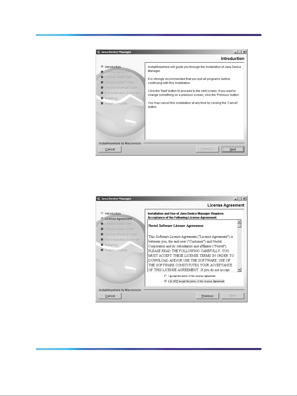
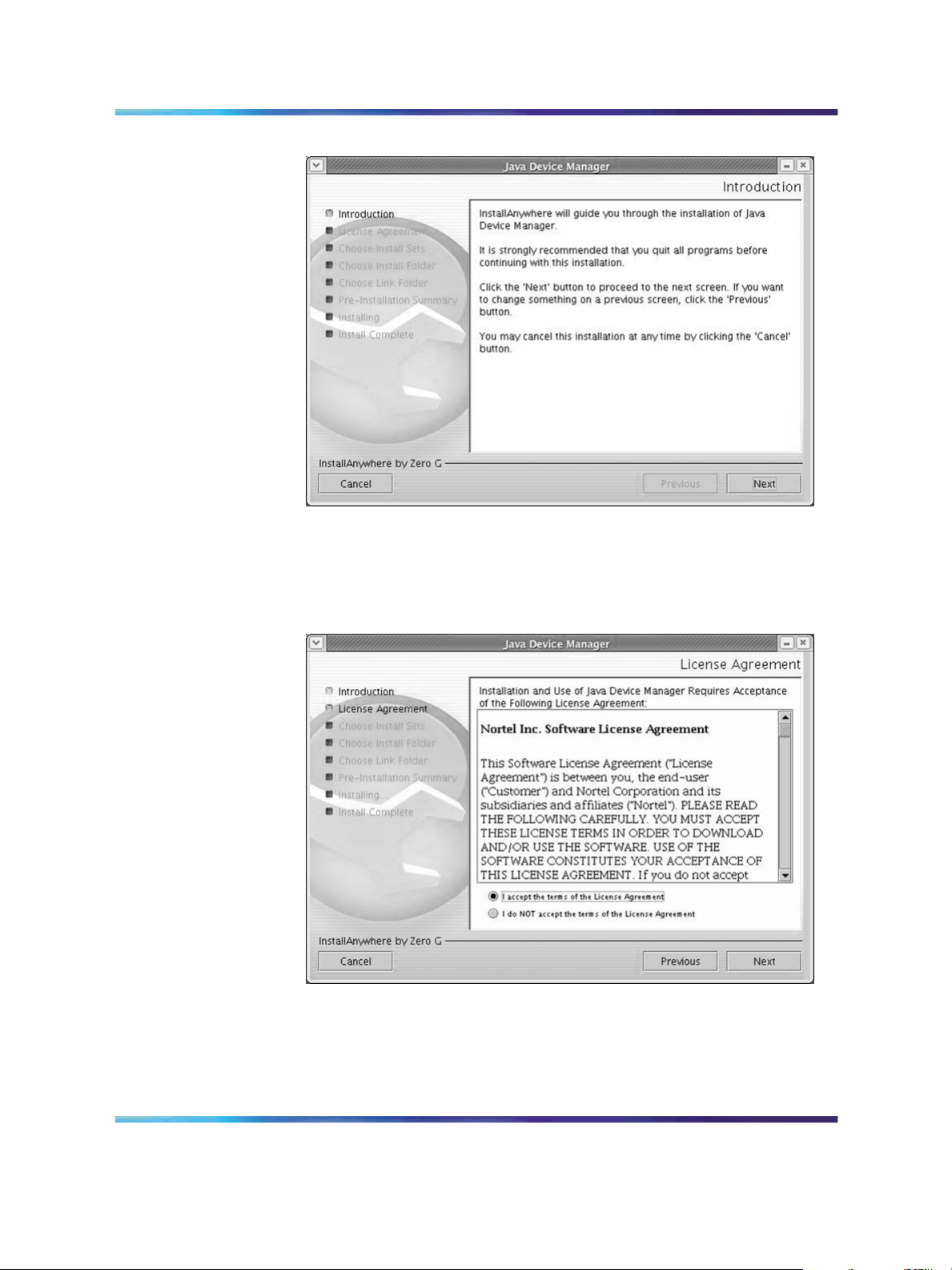
Introduction dialog box
7
Click Next to continue the installation process.
The License Agreement dialog box opens (see "License Agreement
dialog box" (page 14)).
License Agreement dialog box
8
Click I accept the terms of the license agreement (see "License
Agreement dialog box" (page 14)).
9
Copyright © 2005-2007, Nortel Networks
.
Click Next.
Nortel Metro Ethernet Routing Switch 8600
Fundamentals — Using Device Manager
NN46225-300 02.02 Standard
4.2 1 October 2007
Page 15
Installing Device Manager on Windows 15
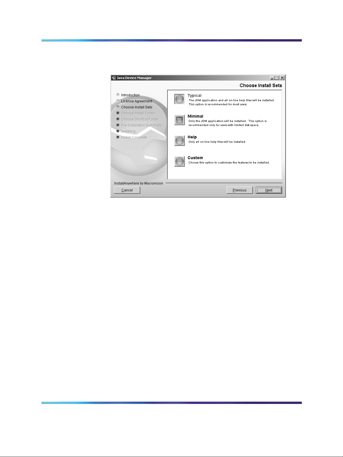
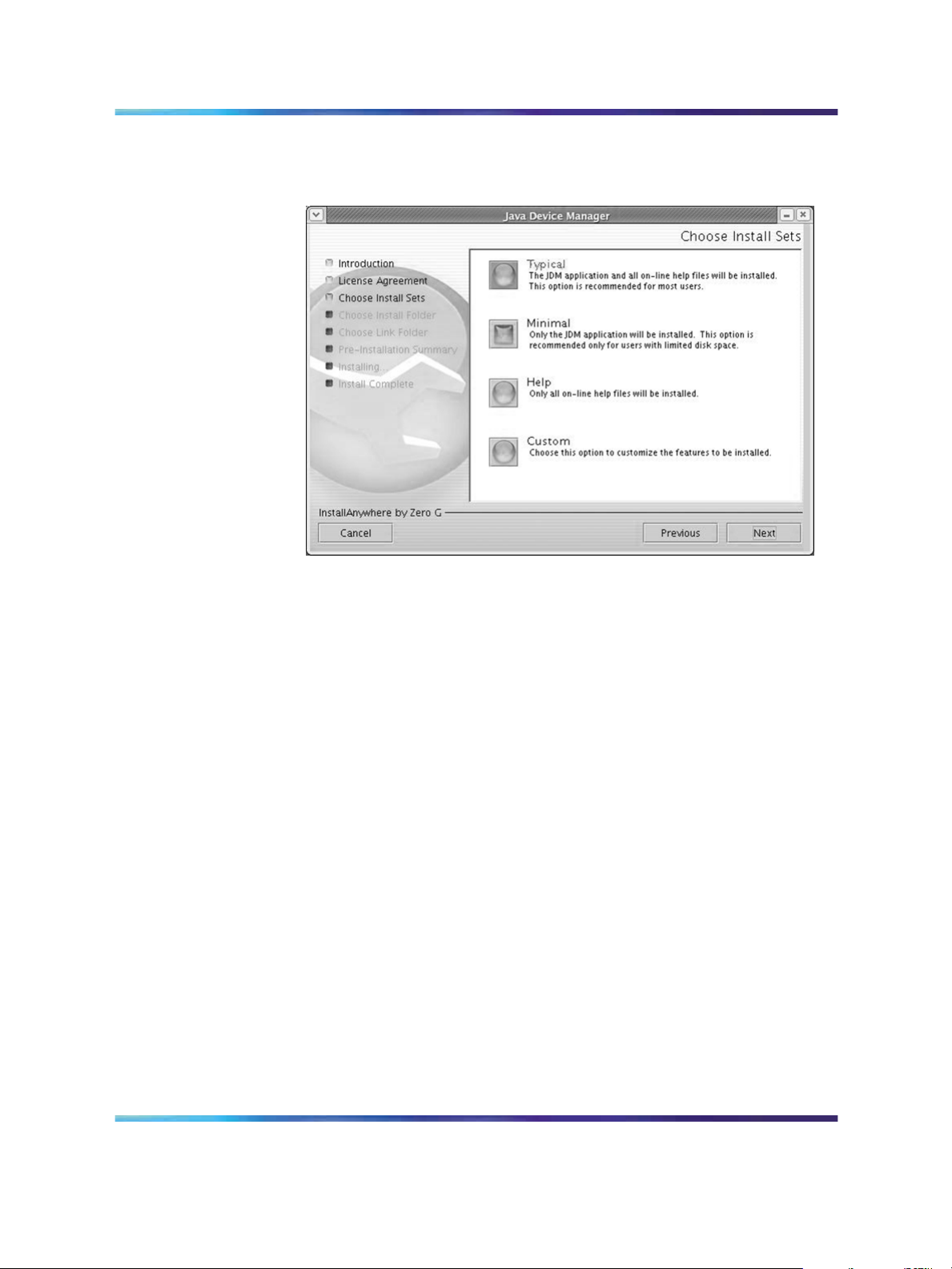
The Choose Install Sets dialog box opens (see "Choose Install Sets
dialog box" (page 15)).
Choose Install Sets dialog box
10
11
Do one of the following:
•
Select Typical installation to install the common set features,
as well as online Help.
•
Select Minimal installation to select minimal features to install
(recommended for those with limited disk space).
•
Select Help to install only the online Help.
•
Select Custom installation to customize the features prior to
installation.
Click Next.
The Choose Install Folder dialog box opens (see "Choose Install
Folder dialog box" (page 16)).
Copyright © 2005-2007, Nortel Networks
.
Nortel Metro Ethernet Routing Switch 8600
Fundamentals — Using Device Manager
NN46225-300 02.02 Standard
4.2 1 October 2007
Page 16
16 Installing Device Manager software
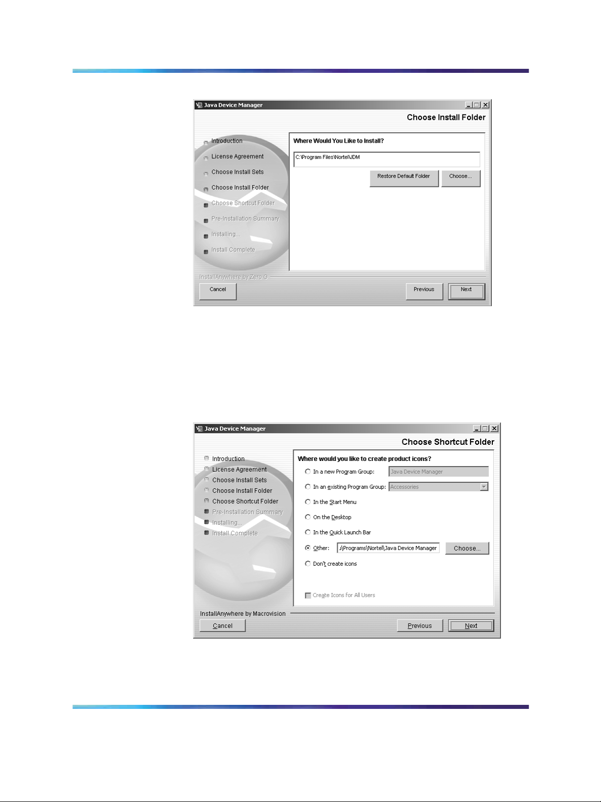
Choose Install Folder dialog box
12
13
Click Restore Default Folder or click Choose to select the storage
path.
Click Next.
The Choose Shortcut Folder dialog box opens (see "Choose
Shortcut Folder dialog box" (page 16)).
Choose Shortcut Folder dialog box
14
15
Copyright © 2005-2007, Nortel Networks
.
Select a shortcut path, if desired.
Click Next.
Nortel Metro Ethernet Routing Switch 8600
Fundamentals — Using Device Manager
NN46225-300 02.02 Standard
4.2 1 October 2007
Page 17
Installing Device Manager on Windows 17
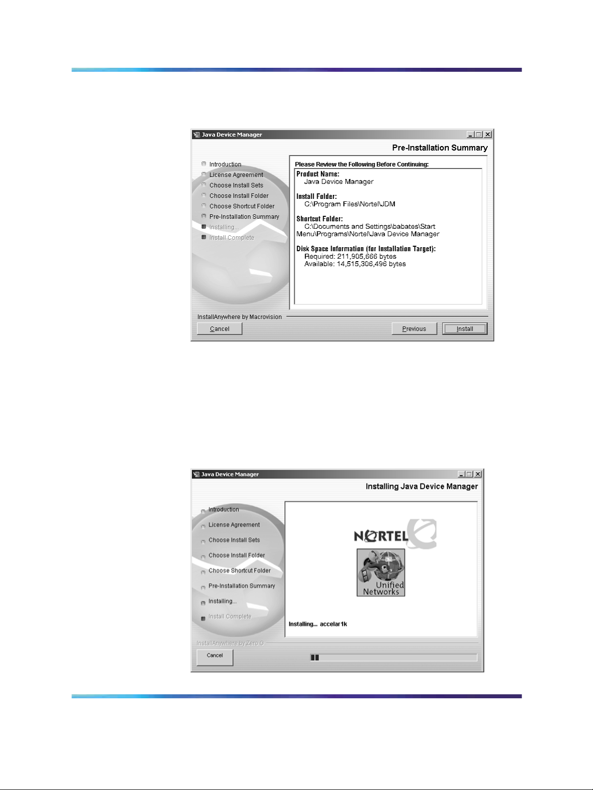
The Pre-Installation Summary dialog box opens (see "Pre-installation
Summary dialog box" (page 17)).
Pre-installation Summary dialog box
16
17
Verify the folder, shortcut, and disk space required to install the
software. Use the Previous button to return to the appropriate dialog
box to make changes.
Click Install.
The installation process begins(see "Installing Java Device Manager
dialog box" (page 17)).
Installing Java Device Manager dialog box
Copyright © 2005-2007, Nortel Networks
.
Nortel Metro Ethernet Routing Switch 8600
Fundamentals — Using Device Manager
NN46225-300 02.02 Standard
4.2 1 October 2007
Page 18
18 Installing Device Manager software
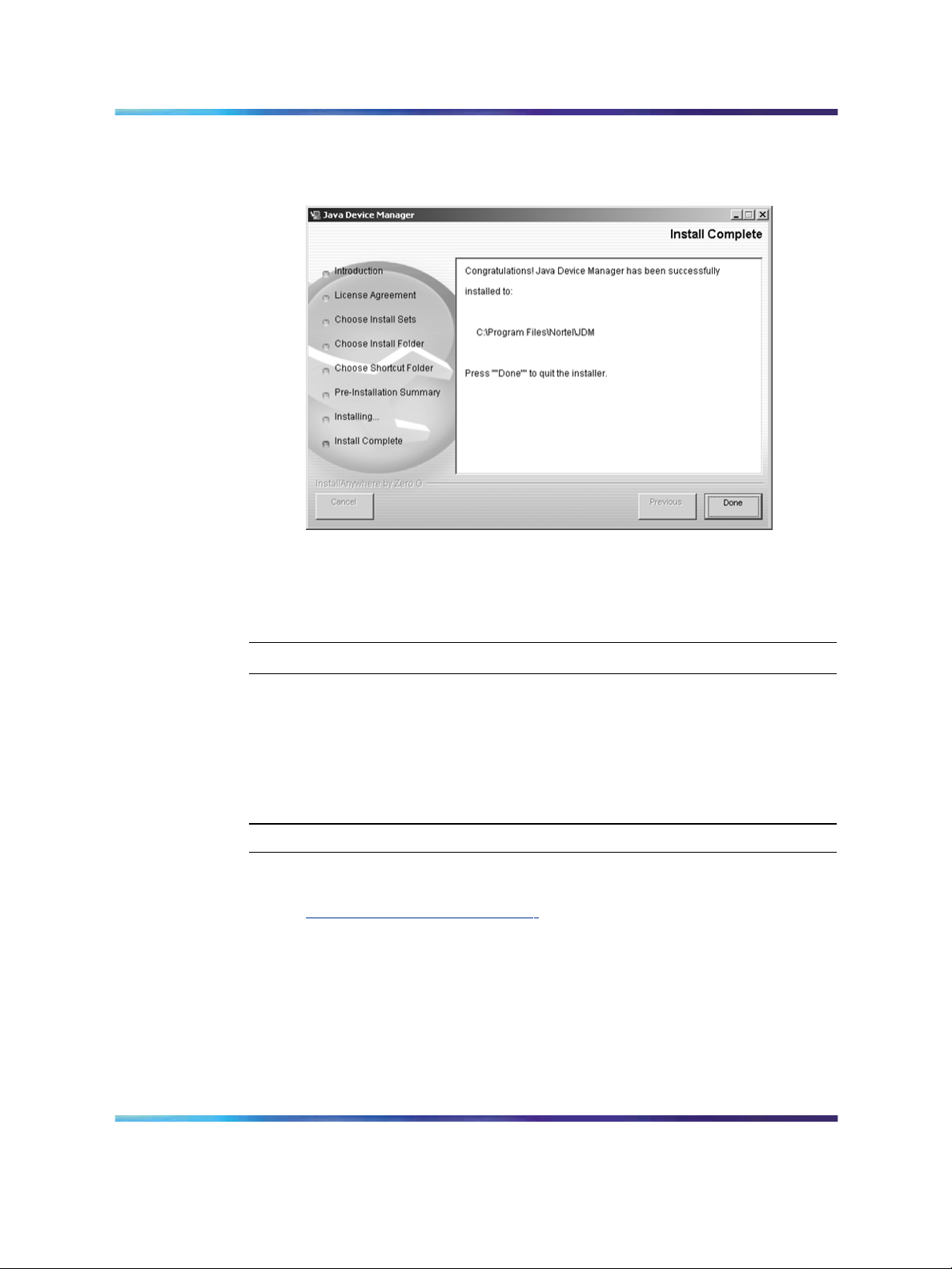
When the installation is complete, the Install Complete dialog box
opens (see "Install Complete dialog box" (page 18)).
Install Complete dialog box
18
Click Done to exit the installation.
Device Manager is now completely installed on your machine. For
instructions on starting the Device Manager software, see Chapter 2.
—End—
Installing Device Manager on Windows from the Web
Use this procedure to obtain the Device Manager software from the Nortel
web site.
Procedure steps
Step Action
1
2
3
Go to the following URL:
ttp://www.nortel.com/support
h
In the Documentation, Software and Bulletins category, click Network
Management.
In the Switches & Routers category, click Java Device Manager.
4
5
Copyright © 2005-2007, Nortel Networks
.
Click Software.
In the Software category, click Releases.
Nortel Metro Ethernet Routing Switch 8600
Fundamentals — Using Device Manager
NN46225-300 02.02 Standard
4.2 1 October 2007
Page 19

Installing Device Manager on UNIX 19
A page listing available versions of the software opens.
6
7
Click the Java Device Manager version for the release you want.
Select Java Device Manager for MS-Windows.
A File Download dialog box opens, asking you to either run this
program from its current location or to download the Device Manager
software to your system.
8
Choose the directory to which you want to download the software.
The software download is a self-extracting .exe file.
Note that in the file name, xxxx represents the current version of
the Device Manager software.
9
Close all programs.
10 Navigate to the directory on your system where you downloaded
the Device Manager software.
11
Double-click the jdm_xxxx.exe file.
An installation screen opens, followed by a Nortel dialog box. Then,
the Introduction dialog box appears. Go to "Introduction dialog box"
(page 14) and complete steps 7 through 18.
—End—
Installing Device Manager on UNIX
Device Manager installation procedures are now standardized across all
platforms. In addition, the required Java Runtime Environment (JRE) (version
1.6.0) is now part of the Device Manager installation package and does not
require a separate installation. The bundled JRE will be used with Device
Manager only and should not affect other Java applications on the same system.
For Solaris, certain Operating System (OS) patches are required for Device
Manager and JRE to function properly. Consult Sun Microsystems to install the
appropriate OS patches before launching Device Manager.
Navigation
•
"Installing Device Manager in a UNIX environment" (page 20)
•
"Installing Device Manager on Linux from the CD" (page 20)
•
"Installing Device Manager on Solaris from the CD" (page 20)
•
"Installing Device Manager on UNIX from the Web" (page 21)
Nortel Metro Ethernet Routing Switch 8600
Fundamentals — Using Device Manager
NN46225-300 02.02 Standard
Copyright © 2005-2007, Nortel Networks
.
4.2 1 October 2007
ATTENTION
Page 20

20 Installing Device Manager software
•
"Executing the Device Manager installation software on UNIX" (page 22)
Installing Device Manager in a UNIX environment
Installing the Device Manager software in a UNIX environment includes:
1. Uninstalling the previous version of Device Manager
2. Installing the Device Manager software
The minimum system requirements for installing Device Manager on a PC
running the Linux Kernel 2.2 (or later) operating system are as follows:
• 4 MB available in a temporary directory
•
400 MB free in the directory where you want to install the Device
Manager software
•
512 MB DRAM
The minimum system requirements for installing Device Manager on a UNIX
SPARC workstation running the Sun Solaris 8, 9, or 10 operating system
are as follows:
•
4 MB available in a temporary directory
•
400 MB free in the directory where you want to install the Device
Manager software
•
512 MB DRAM
Installing Device Manager on Linux from the CD
Use this procedure to install the Device Manager software to a Linux
environment from the CD.
Procedure steps
Step Action
1
2
Navigate to the Linux/JDM subdirectory on the software CD.
Refer to steps 3 to 14 in "Executing the Device Manager installation
software on UNIX" (page 22) for the remaining instructions on how
to install the Device Manager software in a UNIX environment.
—End—
Installing Device Manager on Solaris from the CD
Use this procedure to install the Device Manager software to a Solaris
environment from the CD.
Copyright © 2005-2007, Nortel Networks
.
Nortel Metro Ethernet Routing Switch 8600
Fundamentals — Using Device Manager
NN46225-300 02.02 Standard
4.2 1 October 2007
Page 21

Procedure steps
Step Action
Installing Device Manager on UNIX 21
1
2
Navigate to the Solaris/JDM subdirectory on the software CD.
Refer to steps 3 to 14 in "Executing the Device Manager installation
software on UNIX" (page 22) for the remaining instructions on how
to install the Device Manager software in a UNIX environment.
—End—
Installing Device Manager on UNIX from the Web
Use this procedure toinstall the Device Manager software to an UNIX (Linux
or Solaris) environment from the Web.
Procedure steps
Step Action
1
2
3
Go to the following URL:
ttp://www.nortel.com/support
h
In the Documentation, Software and Bulletins category, click Network
Management.
In the Switches & Routers category, click Java Device Manager.
4
5
Click Software.
In the Software category, click Releases.
A page listing available versions of the software opens.
6
7
Click the Java Device Manager version for the release you want.
Select Java Device Manager for either Sun Solaris Systems or Linux
Systems, depending on what you want to install.
A File Download dialog box opens, asking you to either run this
program from its current location or to download the Device Manager
software to your system.
8
9
Choose a directory to which you want to download the software.
See "Executing the Device Manager installation software on UNIX"
(page 22) for the remaining instructions on how to install the Device
Manager software in a UNIX environment.
Copyright © 2005-2007, Nortel Networks
.
—End—
Nortel Metro Ethernet Routing Switch 8600
Fundamentals — Using Device Manager
NN46225-300 02.02 Standard
4.2 1 October 2007
Page 22

22 Installing Device Manager software
If several warning messages are displayed after you launch Device Manager
on a Solaris workstation, do the following:
•
Add the following statement to your .cshrc file:
setenv XKEYSYMDB $HOME/ .XKeysymDB
•
Make sure there is a .XKeysymbDB file in your home directory.
Executing the Device Manager installation software on UNIX
Use this procedure to execute the Device Manager installation software in
a UNIX environment.
Procedure steps
Step Action
1
2
Close all programs.
Navigate to the directory on your system where you loaded the
Device Manager software.
3
For the Linux environment, make the file executable by entering:
chmod a+x jdm_ xxxx_linux.sh
For the Solaris environment, make the file executable by entering:
chmod a+x dm_xxxx_solaris_sparc.bin
4
For the Linux environment, run the jdm_xxxx_linux.sh file.
For the Solaris environment, run the dm_xxxx_so-
laris_sparc.bin file.
An installation screen, followed by a Nortel dialog box opens.
Then, the Introduction dialog box appears (see "InstallAnywhere
Introduction dialog box" (page 23)).
Copyright © 2005-2007, Nortel Networks
.
Nortel Metro Ethernet Routing Switch 8600
Fundamentals — Using Device Manager
NN46225-300 02.02 Standard
4.2 1 October 2007
Page 23
Installing Device Manager on UNIX 23
InstallAnywhere Introduction dialog box
5
Click Next to continue the installation process.
The License Agreement dialog box opens (see "License Agreement
dialog box" (page 23)).
License Agreement dialog box
6
Click I accept the terms of the License Agreement (see "License
Agreement dialog box" (page 23)).
7
Copyright © 2005-2007, Nortel Networks
.
Click Next.
Nortel Metro Ethernet Routing Switch 8600
Fundamentals — Using Device Manager
NN46225-300 02.02 Standard
4.2 1 October 2007
Page 24
24 Installing Device Manager software
The Choose Install Sets dialog box opens (see "Choose Install Sets
dialog box" (page 24)).
Choose Install Sets dialog box
8
Do one of the following:
•
Select Typical installation to install the common set features,
as well as online Help.
•
Select Minimal installation to select minimal features to install
(recommended for those with limited disk space).
•
Select Help to install only the online Help.
•
Select Custom installation to customize the features prior to
installation.
9
Click Next.
The Choose Install Folder dialog box opens (see "Choose Install
Folder dialog box" (page 25)).
Copyright © 2005-2007, Nortel Networks
.
Nortel Metro Ethernet Routing Switch 8600
Fundamentals — Using Device Manager
NN46225-300 02.02 Standard
4.2 1 October 2007
Page 25

Choose Install Folder dialog box
Installing Device Manager on UNIX 25
10
11
Click Restore Default Folder or click Choose to select the storage
path.
Click Next.
The Pre-Installation Summary dialog box opens (see "Pre-installation
Summary dialog box" (page 25)).
Pre-installation Summary dialog box
Copyright © 2005-2007, Nortel Networks
.
Nortel Metro Ethernet Routing Switch 8600
Fundamentals — Using Device Manager
NN46225-300 02.02 Standard
4.2 1 October 2007
Page 26

26 Installing Device Manager software
12
13
Verify the folder and disk space required to install the software.
Use the Previous button to return to the appropriate dialog box to
make changes.
Click Install.
The installation process begins(see "Installing Java Device Manager
dialog box" (page 26)).
Installing Java Device Manager dialog box
When the installation is complete, the Install Complete dialog box
opens (see "Install Complete dialog box" (page 27)).
Copyright © 2005-2007, Nortel Networks
.
Nortel Metro Ethernet Routing Switch 8600
Fundamentals — Using Device Manager
NN46225-300 02.02 Standard
4.2 1 October 2007
Page 27

Install Complete dialog box
Installing Device Manager on UNIX 27
14
Click Done to exit the installation.
Device Manager is now completely installed on your machine.
—End—
Copyright © 2005-2007, Nortel Networks
.
Nortel Metro Ethernet Routing Switch 8600
Fundamentals — Using Device Manager
NN46225-300 02.02 Standard
4.2 1 October 2007
Page 28

28 Installing Device Manager software
Copyright © 2005-2007, Nortel Networks
.
Nortel Metro Ethernet Routing Switch 8600
Fundamentals — Using Device Manager
NN46225-300 02.02 Standard
4.2 1 October 2007
Page 29

Starting Device Manager
This chapter describes the basic procedures for starting the Device
Manager.
Navigation
•
"Setting the IP address" (page 29)
•
"Starting Device Manager using Windows and UNIX" (page 29)
•
"Setting the Device Manager properties" (page 31)
•
"Opening a device" (page 36)
Setting the IP address
Before you can manage a switch or service unit using Device Manager, you
must set an IP address using the Command Line Interface (CLI):
• For information on setting the Metro Ethernet Routing Switch 8600 IP
address, see Nortel Metro Ethernet Routing Switch 8600 Commissioning
(NN46220-309).
29
•
For information on setting the ESU 1800 or 1850 IP address, see
Nortel Metro Ethernet Services Unit 1800 and 1850 Commissioning
(NN46212-303).
Starting Device Manager using Windows and UNIX
To start Device Manager, do one of the following:
• In the Windows environment, from the Windows Start menu, choose
Programs > Nortel > Java Device Manager > DM.
•
In a UNIX environment, verify that the Device Manager installation
directory is in your search path, then type:
JDM
An abbreviated Device Manager window opens, as shown in "Abbreviated
Device Manager window" (page 30).
Nortel Metro Ethernet Routing Switch 8600
Fundamentals — Using Device Manager
NN46225-300 02.02 Standard
Copyright © 2005-2007, Nortel Networks
.
4.2 1 October 2007
Page 30

30 Starting Device Manager
On startup, Device Manager performs a DNS lookup for the machine on which it
is running. If the DNS lookup is slow or fails, a timeout message appears.
Abbreviated Device Manager window
ATTENTION
Replicating editable fields in Device Manager
Use this procedure to replicate all editable table cells.
Procedure steps
Step Action
1
2
3
4
5
Copyright © 2005-2007, Nortel Networks
.
Click the cell.
The cell is highlighted. (Note: A double-click makes the cell editor
available. The cell editor allows you to directly update the value,
open an option item list or open a dialog. If required, update the cell
prior to highlighting it to be copied.)
Click the Copy icon.
Highlight the cell or cells in which you want to copy the data.
Click the Paste icon.
The content in the first cell is replicated into the highlighted cells.
Click Apply to set the change or click the Arrow icon to reset the
change.
Nortel Metro Ethernet Routing Switch 8600
Fundamentals — Using Device Manager
NN46225-300 02.02 Standard
4.2 1 October 2007
Page 31

—End—
Setting the Device Manager properties
Device Manager uses the Simple Network Management Protocol (SNMP)
to configure and manage the Optical Ethernet Services Solution (OESS)
switches. You can use the Device Manager Properties dialog box to
configure important communication parameters such as the polling interval,
timeout, and retry count. You can set these parameters at any time before
or after you open a device.
Device Manager keeps a set of default, or global, properties that apply to
all devices, and a set of properties for each device. The default properties
are used when you open a device for the first time. A copy of the properties
are saved for each device that is opened. You can customize the properties
for a particular device as required.
Use this procedure to set the Device Manager default properties.
Procedure steps
Setting the Device Manager properties 31
Step Action
1
If you do not have a device open, from the Device Manager menu
bar, choose Device > Properties > Current.
OR
If you have a device open, from the Device Manager menu bar,
choose Device > Properties > Devices. Select Default in the
Properties Device List box, and then click Edit.
The Default Properties dialog box opens (see the following figure).
Copyright © 2005-2007, Nortel Networks
.
Nortel Metro Ethernet Routing Switch 8600
Fundamentals — Using Device Manager
NN46225-300 02.02 Standard
4.2 1 October 2007
Page 32

32 Starting Device Manager
Default Properties
2
Select the properties you want to change and set their values.
For information about the property fields, see "Variable definitions"
(page 32).
3 Click Ok.
—End—
Variable definitions
Variable Value
Status Interval Interval at which statistics and status
information are gathered (default is 20
seconds).
Hotswap Detect every The number of intervals at which
Device Manager will check for module
hot swaps.
Enable If selected, Device Manager will poll the
switch according to the settings listed
above the Enable check box.
Retry Count If Device Manager cannot transmit
polling information at startup, the
number of times Device Manager
retransmits polling information.
Copyright © 2005-2007, Nortel Networks
.
Nortel Metro Ethernet Routing Switch 8600
Fundamentals — Using Device Manager
NN46225-300 02.02 Standard
4.2 1 October 2007
Page 33

Setting the Device Manager properties 33
Timeout Length of each retry of each polling
waiting period. When accessing the
device through a slow link, you may
want to increase the timeout interval
and then change the Retransmission
Strategy to superlinear.
Trace If selected, you can perform trace
routes.
Listen for Traps If selected, Device Manager will listen
for a trap.
When you operate Device Manager
from a UNIX platform, you must be
logged in as root in order to receive
traps.
By default, traps are sent in SNMP
V2c format. However, if you are using
an older network management system
(NMS) that supports only SNMP V1
traps (HP OpenView), you can select
that the traps be sent in V1 format.
The management station operating with
Device Manager is automatically added
to the device trap receiver table.
Max Traps in Log The maximum number of traps that can
exist in the trap log. The default is 500.
Trap Port The number of the port that trap
messages are captured on. The default
port for trap messages is 162.
Listen for Syslogs If selected, Device Manager will listen
for syslogs.
Confirm row deletion If selected, Device Manager will send
a message when a system table row
is deleted.
Default Read Community The default Read Community type.
You can edit this field by highlighting
the current value and typing over it.
Default Write Community The default Write Community type. You
can edit this field by highlighting the
current value and typing over it.
Http Port The default port used for web interface.
This property cannot be changed for
this dialog box.
Copyright © 2005-2007, Nortel Networks
.
Nortel Metro Ethernet Routing Switch 8600
Fundamentals — Using Device Manager
NN46225-300 02.02 Standard
4.2 1 October 2007
Page 34

34 Starting Device Manager
Application launch with ring tone When checked, the ring tone will sound
Save SNMPv3 Devices to Open Last When checked, you can open a device
every time you launch Device Manager.
This is the default behavior.
using Device > Open Last by SNMPv3
without reentering the required
SNMPv3 authentication information.
Note, however, that this is not secure.
JDM prompts with a warning message
that indicates a possible security threat
because the devise opens without
having to enter security information.
When this box is unchecked, the saved
SNMPv3 authentication information for
all devices is erased. JDM prompts you
to verify the change.
JDM resets the required parameters
for the devices open using SNMPv3
only when this option is enabled. In
this case, you can select a device
from a list of devices that Device
Manager has accessed through
SNMPv3 without having to enter
the required SNMPv3 user name,
authentication protocol/password, and
privacy protocol/password again.
Telnet By default, Device Manager uses the
Telnet that comes with the operating
system. To specify a different Telnet,
click User-Defined and specify the
path. Specify any parameters in the
Parameter(s) box.
SSH By default, Device Manager uses the
SSH that comes with the operating
system. To specify a different SSH,
click User-Defined and specify the
path. Specify any parameters in the
Parameter(s) box.
Viewing and customizing per device properties
Use this procedure to view and customize the per device property settings.
Procedure steps
Step Action
1
If you have a device open, from the Device Manager menu bar,
choose Device > Properties > Current.
Copyright © 2005-2007, Nortel Networks
.
Nortel Metro Ethernet Routing Switch 8600
Fundamentals — Using Device Manager
NN46225-300 02.02 Standard
4.2 1 October 2007
Page 35

Setting the Device Manager properties 35
OR
If you do not have a device open, from the Device Manager menu
bar, choose Device > Properties > Devices. Select the device IP
address in the Properties Device List box, and then click Edit.
The properties dialog box for the selected device opens (see the
following figure).
Device Properties
2
Select the properties you want to change and set their values.
For information about the device properties field descriptions, see
"Variable definitions" (page 35)
Settings that are gray are global default settings; you can only view
them.
Variable definitions
Variable Value
Retry Count If Device Manager cannot transmit
Copyright © 2005-2007, Nortel Networks
.
—End—
polling information at startup, the
number of times Device Manager
retransmits polling information.
Nortel Metro Ethernet Routing Switch 8600
Fundamentals — Using Device Manager
NN46225-300 02.02 Standard
4.2 1 October 2007
Page 36

36 Starting Device Manager
Timeout Length of each retry of each polling
Trace If selected, you can perform trace
Listen for Traps If selected, Device Manager will listen
waiting period. When accessing the
device through a slow link, you may
want to increase the timeout interval
and then change the Retransmission
Strategy to superlinear.
routes.
for a trap.
When you operate Device Manager
from a UNIX platform, you must be
logged in as root in order to receive
traps.
By default, traps are sent in SNMP
V2c format. However, if you are using
an older network management system
(NMS) that supports only SNMP V1
traps (HP OpenView), you can select
that the traps be sent in V1 format.
Max Traps in Log The maximum number of traps that can
Listen for Syslogs If selected, Device Manager will listen
Default Read Community The default Read Community type.
Default Write Community The default Write Community type. You
Http Port Specify the port to use for the web
Opening a device
Opening a device displays the device view, a picture of the device. Before
you can display the device view, you must enter community strings that
determine the access level granted to the device. Use this procedure to
open a device
The management station operating with
Device Manager is automatically added
to the device trap receiver table.
exist in the trap log. The default is 500.
for syslogs.
You can edit this field by highlighting
the current value and typing over it.
can edit this field by highlighting the
current value and typing over it.
interface. To access the device home
page with WEB UI, Http Port must be
the same as the switch configuration.
Copyright © 2005-2007, Nortel Networks
.
Nortel Metro Ethernet Routing Switch 8600
Fundamentals — Using Device Manager
NN46225-300 02.02 Standard
4.2 1 October 2007
Page 37

Procedure steps
Step Action
Opening a device 37
1
From the abbreviated Device Manager window menu bar, choose
Device > Open.
OR
From the Device Manager toolbar, click the Open Device button.
The Open Device dialog box opens (see the following figure).
Open Device dialog box
For information, see "Variable definitions" (page 38) .
2
In the Device Name field, identify the device by entering the DNS
name or IP address of the device.
3
In the Read Community and Write Community fields, enter the
proper community strings.
To gain read/write/all access to a device in Device Manager, you
must enter the read/write/all community string for both the Read
Community and Write Community strings. For information, see
"SNMP community string default values" (page 38) .
4
Check the v3 Enabled checkbox to enable SNMP version 3. Clear
the checkbox to disabled SNMP version 3.
5
Click Ping to check if the switch is reachable, or click Telnet to
initiate a Telnet session.
Copyright © 2005-2007, Nortel Networks
.
Nortel Metro Ethernet Routing Switch 8600
Fundamentals — Using Device Manager
NN46225-300 02.02 Standard
4.2 1 October 2007
Page 38

38 Starting Device Manager
6
Click Open.
—End—
Variable definitions
Variable Value
Device Name Enter the DNS name or IP address of the device.
Read Community Enter the read community password string to use
to open this device.
Write Community Enter the write community password string to use
to open this device.
Use default community
string in properties
v3 Enabled Enables (selected) or disables (cleared) SNMP
User Name Indicates the user’s security name. If v3 Enabled is
When selected, the community strings in the device
specific properties are used to open this device. If
the device specific properties do not exit, the global
default properties will be used.
version 3.
selected, this name appears in the Edit > SnmpV3
tables.
Context Name A string between 0 and 32 characters that identifies
a context for accessing management information at
a SNMP entity. Required for certain devices.
Authentication Protocol Indicates the selected authentication protocol:
NONE, MD5, or SHA-96.
Authentication Password Indicates the authentication password string.
Privacy Protocol Indicates the selected privacy protocol: NONE,
DES, or AES.
Privacy Password Indicates the privacy password string.
SNMP community string default values
Access Level Description
read-only Public
Layer 1 read/write Private
Layer 2 read/write Private
Layer 3 read/write Private
read/write Private
read/write/all Secret
Copyright © 2005-2007, Nortel Networks
.
Nortel Metro Ethernet Routing Switch 8600
Fundamentals — Using Device Manager
NN46225-300 02.02 Standard
4.2 1 October 2007
Page 39

Device view
When a device is opened, Device Manager automatically determines what
version of software the selected device is running; a picture of the device
that represents its physical features appears.
"Device Manager window for a Metro Ethernet Routing Switch 8600 switch"
(page 39) shows this window for the Metro Ethernet Routing Switch 8600,
"Device Manager window for a Metro ESU 1800 switch" (page 40) shows
it for the Metro ESU 1800, and "Device Manager window for a Metro ESU
1800 switch" (page 40) shows it for the Metro ESU 1850.
For information about connecting to the switch using SNMPv3, refer to
Managing Network Operations (315545-E) and Configuring and Managing
Security (314724-E).
Device Manager window for a Metro Ethernet Routing Switch 8600 switch
Opening a device 39
Copyright © 2005-2007, Nortel Networks
.
Nortel Metro Ethernet Routing Switch 8600
Fundamentals — Using Device Manager
NN46225-300 02.02 Standard
4.2 1 October 2007
Page 40

40 Starting Device Manager
Device Manager window for a Metro ESU 1800 switch
Device Manager window for a Metro ESU 1850 switch
Opening a device using the Open Last option
Use this procedure to view or select a device from a list of available devices
with the Open Last option in Device Manager.
Procedure steps
Step Action
1
2
To delete devices from the Open Last Device List, choose Device > Open
Last > Edit. The Devices dialog box opens. Highlight the device that you
want to remove from the list and click Delete.
From the abbreviated Device Manager window menu bar, choose
Device > Open Last.
A drop-down menu appears, listing the devices that were previously
opened. The Open Last Device List displays up to 24 devices at a
time. You can view additional devices by selecting Device List 1,
Device List 2, and so forth.
Choose the IP address or system name of the device that you want
to open. The Open Device dialog box for that device opens.
If you are not able to open a device in Device Manager, see "Switch
fails to open in Device Manager" (page 76) for information about
how to troubleshoot the problem.
—End—
Copyright © 2005-2007, Nortel Networks
.
Nortel Metro Ethernet Routing Switch 8600
Fundamentals — Using Device Manager
NN46225-300 02.02 Standard
4.2 1 October 2007
Page 41

Understanding the Device Manager window
The Device Manager window has the following four parts:
•
menu bar
•
toolbar
•
device view
•
status bar
The graphic that follows (see "Parts of the Device Manager window" (page
42)) displays the parts of the Device Manager window for the Metro Ethernet
Routing Switch 8600. The Metro ESU 1800 and Metro ESU 1850 are
organized in a similar manner.
41
Copyright © 2005-2007, Nortel Networks
.
Nortel Metro Ethernet Routing Switch 8600
Fundamentals — Using Device Manager
NN46225-300 02.02 Standard
4.2 1 October 2007
Page 42

42 Understanding the Device Manager window
Parts of the Device Manager window
Navigation
•
"Using the menu bar" (page 42)
•
"Using the toolbar" (page 45)
•
"Using the device view" (page 47)
•
"Using the status bar" (page 52)
•
"Using Device Manager dialog boxes" (page 53)
•
"Online Help" (page 55)
Using the menu bar
The menu bar on the Device Manager window (see "Menu bar" (page 43))
provides menus with commands that let you monitor the Metro Ethernet
Routing Switch 8600, Metro ESU 1800, and Metro ESU 1850.
Copyright © 2005-2007, Nortel Networks
.
Nortel Metro Ethernet Routing Switch 8600
Fundamentals — Using Device Manager
NN46225-300 02.02 Standard
4.2 1 October 2007
Page 43

Menu bar
Menu bar descriptions
"Device Manager menu bar descriptions, Metro Ethernet Routing Switch
8600" (page 43) describes the menu bar fields for the Metro Ethernet
Routing Switch 8600.
Device Manager menu bar descriptions, Metro Ethernet Routing Switch 8600
Menu Description
Device The Device menu lets you open a device, refresh the device
view, and set polling and SNMP properties.This menu also
allows you to initiate a Telnet session, or open and view the
Trap Log, Sys Log, and Log.
Using the menu bar 43
Edit The Edit menu lets you view parameters for the chassis or for
selected objects. The object can be a card, fan, MDA, port,
power supply, or any other object. This menu also lets you run
diagnostic tests, configure Asynchronous Transfer Mode (ATM),
NTP, and SNMPv3 parameters, view the status of a controlled
software upgrade, and select all objects in the device.
Graph The Graph menu lets you view Device Manager statistics and
produce graphs of the chassis, WSM card, or port statistics.
VLAN The VLAN menu lets you view information about VLANs,
spanning tree groups (STG), MultiLink Trunking/Link
Aggregation Control Protocol (MLT/LACP), MAC Learning,
Split MultiLink Trunking (SMLT), stacked VLANs (SVLAN), and
Simple Loop Prevention Policy (SLPP).
IP Routing The IP Routing menu lets you set up IP routing functions for
the switch, including Open Shortest Path First (OSPF), Routing
Information Protocol (RIP), Border Gateway Protocol (BGP),
Virtual Redundancy Router Protocol (VRRP), Multicast, Internet
Group Membership Protocol (IGMP), Distance Vector Multicast
Routing Protocol (DVMRP), Protocol Independent Multicast
(PIM), Pragmatic General Multicast Protocol (PGM), DHCP,
Routed Split MultiLink Trunking (RSMLT), UDP forwarding,
filters, and policies. (See Note 1.)
Copyright © 2005-2007, Nortel Networks
.
Nortel Metro Ethernet Routing Switch 8600
Fundamentals — Using Device Manager
NN46225-300 02.02 Standard
4.2 1 October 2007
Page 44

44 Understanding the Device Manager window
Menu Description
IPX Routing
The IPX Routing menu lets you set up IPX routing functions,
including RIP, Service Access Protocol (SAP), and policies.
(See Note 2.)
Security The Security menu lets you set security parameters for the
various control and data paths.
VPN The VPN menu lets you set up PBB, PBT and OLE2 services as
well as your PBT trunks, Continuity Fault Management (CFM),
and Transparent Domain Continuity (TDC); configure UNIs,
Customer IP VLANs, and Transparent Domain Identifers (TDI);
and configure Performance Monitoring (PM) profiles and view
PM connection metrics.
QOS The QOS menu lets you set up and view Quality of Service
(QoS) profiles, and traffic management. This menu also lets you
configure QoS policies, subport queue sets, Weighted Random
Early Detection (WRED) thresholds, and Drop Trap profiles.
In addition, you can view the ingress, egress, and color maps,
and policy statistics.
RMON The RMON menu lets you set up remote monitoring (RMON)
alarms and view the alarm log. This menu also allows you to
enable or disable RMON history or statistics on all ports.
Actions The Actions menu provides quick access to selected actions
without going through other menus and submenus. Use this
menu to open the Web management interface, to save run-time
or boot configurations, get a PCAP file, or revert back to previous
configurations.
Help The Help menu lets you view online Help topics for Device
Manager. This menu also provides a legend for the port colors
in the device view.
Note 1: The BGP, Multicast, DVMRP, PIM, and PGM routing functions are not
supported when High Availability is enabled.
Note 2: IPX Routing is not supported when High Availability is enabled.
"Device Manager menu bar descriptions, Metro ESU 1800 and 1850" (page
44) describes the menu bar fields for the Metro ESU 1800 and 1850.
Device Manager menu bar descriptions, Metro ESU 1800 and 1850
Menu Description
Device The Device menu lets you open a device, refresh the device
view, and set polling and SNMP properties.This menu also
allows you to initiate a Telnet session and open and view
the Trap Log and Log.
Copyright © 2005-2007, Nortel Networks
.
Nortel Metro Ethernet Routing Switch 8600
Fundamentals — Using Device Manager
NN46225-300 02.02 Standard
4.2 1 October 2007
Page 45

Using the toolbar 45
Menu Description
Edit The Edit menu lets you view parameters for the chassis or
for selected objects, such as ports. This menu also lets you
set security parameters, run diagnostic tests, and select all
objects in the device.
Graph The Graph menu lets you view chassis or port statistics.
IP VLAN The IP VLAN menu lets you set up VLANS for the switch.
IP Routing The IP Routing menu lets you set up IP routing and Quality of
Service (QoS) functions for the switch. It also allows you to
perform traffic control.
Layer 2 The Layer 2 menu lets you set up FDB, GVRP, Internet
Group Membership Protocol (IGMP), Multicast FDB, port
mirroring, Spanning Tree, and current and static VLANs for
Layer 2 mode. The device must be reset for Layer 2 for this
menu to function.
QinQ The Q-in-Q menu lets you set up a VLAN for Q-in-Q mode
(applies to the ESU 1850 only).
Packet
Classification
Rmon TheRMON menu lets you set up and view remote monitoring
Rapid Ping The Rapid Ping menu lets you test traffic data issues such as
Actions The Actions menu provides quick access to selected actions
Help The Help menu lets you view online Help topics for Device
Using the toolbar
The toolbar buttons provide quick access to commonly used commands and
some additional actions for the Metro Ethernet Routing Switch 8600, Metro
ESU 1800, and Metro ESU 1850.
describes the toolbar buttons for the Metro Ethernet Routing Switch 8600,
and Metro ESU 1800 and 1850.
The Packet Classification menu lets you perform filtering,
metering, packet classification, and packet policing.
(RMON) alarms.
connectivity, latency, and packet loss.
without going through other menus and submenus. Use this
menu to open the Web management interface and save
runtime configurations.
Manager. This menu also provides a legend for the port
colors in the device view.
Copyright © 2005-2007, Nortel Networks
.
Nortel Metro Ethernet Routing Switch 8600
Fundamentals — Using Device Manager
NN46225-300 02.02 Standard
4.2 1 October 2007
Page 46

46 Understanding the Device Manager window
Toolbar buttons
Button Name Description Menu equivalent
Open Device Opens a device. Device > Open
Refresh Device
Status
Refreshes the device view
information.
Device > Refresh
Status
Telnet Opens a Telnet session. Device > Telnet
SSH
Opens an SSH session. Device > SSH
Connection
Trap Log Opens the trap log. Device > Trap Log
Help Opens online Help in a
web browser window.
Edit Selected Displays configuration
data windows for the
selected chassis object.
Help > Device
Manager Basics
Edit > Chassis
Edit > WSM Card
Edit > SAM Card
Edit > Card
Edit > Fan
Edit > MDA
Edit > Mgmt Port
Copyright © 2005-2007, Nortel Networks
.
Graph Selected Opens statistics and
graphing windows.
Open Home
Page
Opens the Web
management interface
home page.
Save Runtime
Config
Saves the current
run-time configuration.
Alarm Manager Opens the RMON Alarm
Manager window.
Nortel Metro Ethernet Routing Switch 8600
Fundamentals — Using Device Manager
NN46225-300 02.02 Standard
4.2 1 October 2007
Edit > Port
Edit > Power Supply
Edit > Serial Port
Graph > Chassis
Graph > Port
Actions > Open Home
Page
Actions > Save
Runtime Config
Rmon > Alarm
Manager
Page 47

Using the device view
The device view allows you to determine at a glance the operating status of
the various modules and ports in your hardware configuration. You also use
the device view to perform management tasks on specific objects.
Navigation
•
"Selecting objects" (page 47)
• "Interpreting the status of LEDs and ports" (page 49)
•
"Using shortcut menus" (page 50)
Selecting objects
In the device view, you can select the following types ofobjects for the Metro
Ethernet Routing Switch 8600, and Metro ESU 1800 and 1850:
•
the entire chassis
•
a card (module) or multiple cards
•
a port or multiple ports
•
a console port (Metro ESU 1800 and 1850 only)
Using the device view 47
•
a Media Dependent Adapter (MDA) (Metro ESU 1850 only)
For the Metro Ethernet Routing Switch 8600, you can also select the
following types of objects:
•
a serial port
•
a power supply
•
afan
•
a management port
"Objects in a Metro Ethernet Routing Switch 8600 device view" (page
48) shows these objects in a Metro Ethernet Routing Switch 8600, "Objects
in a Metro ESU 1800 switch device view" (page 48) shows them in the
Metro ESU 1800, "Objects in a Metro ESU 1850 switch device view" (page
49) shows them in the Metro ESU 1850.
Copyright © 2005-2007, Nortel Networks
.
Nortel Metro Ethernet Routing Switch 8600
Fundamentals — Using Device Manager
NN46225-300 02.02 Standard
4.2 1 October 2007
Page 48

48 Understanding the Device Manager window
Objects in a Metro Ethernet Routing Switch 8600 device view
Objects in a Metro ESU 1800 switch device view
Nortel Metro Ethernet Routing Switch 8600
Fundamentals — Using Device Manager
NN46225-300 02.02 Standard
Copyright © 2005-2007, Nortel Networks
.
4.2 1 October 2007
Page 49

Objects in a Metro ESU 1850 switch device view
To select a single object, click the edge of the object. The object is outlined
in yellow, indicating that it is selected. Subsequent activities in Device
Manager refer to the selected object.
To select multiple objects of the same type (such as ports or modules), use
one of the following actions:
•
For a block of contiguous ports or modules, drag to select the group
of objects.
•
For multiple ports or modules anywhere in the switch chassis, press Ctrl
and click the objects anywhere in the device view.
Using the device view 49
The general rule for selecting multiple physical objects, such as fans, power
supplies, modules, and ports, is that the selected objects must belong to the
same category or have some kind of parent/child relationship.
Interpreting the status of LEDs and ports
The conventions on the device view are similar to the actual switch
appearance for the Metro Ethernet Routing Switch 8600, and Metro ESU
1800 and 1850. Module LEDs are in one of three states: on, off, or blinking.
For a full description of what each state means, refer to the documentation
that came with the module.
The ports on the device view are color-coded to provide at-a-glance port
status. "Device Manager port color codes" (page 49) shows the status
assigned to each color.
Device Manager port color codes
Color
Green Port is up and operating.
Red Port has been manually disabled.
Orange Port has no link.
Light Blue Port is in standby mode.
Description
Dark Blue Port is being tested.
Grey Port is not reachable by Device Manager.
Pink Port has a loopback connector connected to it.
Copyright © 2005-2007, Nortel Networks
.
Nortel Metro Ethernet Routing Switch 8600
Fundamentals — Using Device Manager
NN46225-300 02.02 Standard
4.2 1 October 2007
Page 50

50 Understanding the Device Manager window
In addition, the Help menu provides a legend that identifies the port colors
and their meanings.
Using shortcut menus
Objects in the device view, such as the chassis, ports, and cards, have
shortcut menus. These menus provide a faster path for editing objects
and applying changes; however, you can access the same options through
the menu bar or the toolbar.
To display the chassis shortcut menu, select the chassis (see "Chassis
shortcut menu" (page 50)) and right click.
Chassis shortcut menu
For more information, see "Chassis shortcut menu options" (page 50).
Chassis shortcut menu options
"Chassis shortcut menu options, Metro Ethernet Routing Switch 8600"
(page 50) describes the chassis shortcut menu options for the Metro
Ethernet Routing Switch 8600.
Chassis shortcut menu options, Metro Ethernet Routing Switch 8600
Option
Edit Edit chassis parameters.
Graph Graph chassis statistics.
Save Runtime
Config
Save Boot Config Save any changes made as a boot configuration.
Reset Counters Reset all the statistics counters for the switch.
Hard Reset Perform a hard reset of the switch.
Soft Reset Perform a soft reset of the switch.
Description
Save any changes made as a run-time configuration.
Copyright © 2005-2007, Nortel Networks
.
Nortel Metro Ethernet Routing Switch 8600
Fundamentals — Using Device Manager
NN46225-300 02.02 Standard
4.2 1 October 2007
Page 51

Using the device view 51
"Chassis shortcut menu options, Metro ESU 1800 and 1850" (page
51) describes the shortcut menu options for the Metro ESU 1800 and 1850.
Chassis shortcut menu options, Metro ESU 1800 and 1850
Option
Description
Edit Edit chassis parameters.
Graph Graph chassis statistics.
Save Config Save any changes made to the configuration.
Reset Counters Reset all the statistics counters for the switch.
Factory Reset Does not boot the switch. Instead, it returns the configuration
to factory defaults.
System Reset Performs a system restart.
To display the port shortcut menu (see "Port shortcut menu" (page 51)),
select one or more ports and right-click.
Port shortcut menu
Metro ESU 1800 and 1850 Metro Ethernet Routing Switch 8600
Port shortcut menu options
"Port shortcut menu options, Metro ESU 1800 and 1850" (page
51) describes the I/O port shortcut menu options for the Metro ESU 1800
and 1850.
Port shortcut menu options, Metro ESU 1800 and 1850
Option
Edit Display edit port menu.
Graph Graph port statistics.
Enable Administratively bring a port up.
Disable Administratively shut down a port.
Copyright © 2005-2007, Nortel Networks
.
Description
Nortel Metro Ethernet Routing Switch 8600
Fundamentals — Using Device Manager
NN46225-300 02.02 Standard
4.2 1 October 2007
Page 52

52 Understanding the Device Manager window
"Port shortcut menu options, Metro Ethernet Routing Switch 8600" (page
52) describes the I/O port shortcut menu options for the Metro Ethernet
Routing Switch 8600.
Port shortcut menu options, Metro Ethernet Routing Switch 8600
Option
Edit Display edit port menu.
Graph Graph port statistics.
Graph POS Display on POS ports only.
Enable Administratively bring a port up.
Disable Administratively shut down a port.
Enable Rmon
Stats
Enable Rmon
History
Enable
FastStart
Disable
FastStart
Description
Enable Rmon statistics logging on this port or ports. Does not
display on ATM or POS ports.
Enable Rmon history logging on this port or ports. This field
does not display on ATM or POS ports.
Enable FastStart spanning tree operation on this port or
ports. This field does not display on ATM ports.
Disable FastStart spanning tree operation on this port or
ports. This field does not display on ATM ports.
For the Metro Ethernet Routing Switch 8600, the card shortcut menu
provides a quick way to view a card’s parameters. When the selected card
is an I/O module, you can click on the Edit option on the shortcut menu
to open the Edit Card dialog box.
To display the card shortcut menu (see "Card shortcut menu (I/O module)"
(page 52)), select a card and right-click.
Card shortcut menu (I/O module)
Using the status bar
At the bottom of the Device Manager window is the status bar. This area
displays error and informational messages from the software application.
These messages are not related to the device being managed.
Copyright © 2005-2007, Nortel Networks
.
Nortel Metro Ethernet Routing Switch 8600
Fundamentals — Using Device Manager
NN46225-300 02.02 Standard
4.2 1 October 2007
Page 53

Using Device Manager dialog boxes
Many Device Manager dialog boxes contain fields that allow you to enter
values for parameters, and many of the parameters have predetermined
possible values. For example, a port may be set to be enabled or disabled.
Other parameter values are ranges of user-determined values. For example,
the value for a system contact will be a name you enter in the SysContact
field.
Fields that can be modified are displayed in white.
Use this procedure to change the value in a field.
Procedure steps
Step Action
Using Device Manager dialog boxes 53
1
Click the field.
The possible choices for that parameter are displayed. "Parameter
selection menu" (page 53) shows an example of a Metro Ethernet
Routing Switch 8600 field that can be modified.
Parameter selection menu
2
Click a new value from the list.
3 Click Apply.
—End—
For fields that do not have preset values, click the field and type the value.
Using the buttons in Device Manager dialog boxes
"Device Manager buttons" (page 54) describes buttons that appear in
Device Manager dialog boxes and tabs.
Note that all of these buttons do not appear in all of the dialog boxes on the
Metro Ethernet Routing Switch 8600, Metro ESU 1800, and Metro ESU
1850. Specifically, only the first ten buttons listed in the table, with the
exception of Resize Columns, are applicable to the Metro ESU 1800 and
1850.
Copyright © 2005-2007, Nortel Networks
.
Nortel Metro Ethernet Routing Switch 8600
Fundamentals — Using Device Manager
NN46225-300 02.02 Standard
4.2 1 October 2007
Page 54

54 Understanding the Device Manager window
Device Manager buttons
Button Description
Apply Applies the changes you have entered in fields on a tab or
dialog box. The button is dimmed until you change a parameter.
Changes are displayed as bold text or numbers.
Insert Opens a dialog box to create a new entry for a table; then from
the dialog box, inserts the new entry in the table.
Delete Deletes a selected entry.
Refresh Refreshes the information in the window. Every time you click on
Refresh, new information is polled from the switch and displayed.
Close Closes the tab or dialog box and disregards any changes you
have made to fields.
Help Opens context-sensitive online Help.
Resize
Columns
Stop Stops the current action (polling).
Copy Copies selected items to your computer’s memory clipboard.
Paste Pastes the contents of your computer’s clipboard.
Reset
changes
Export data Allows you to copy data to external media.
Print Table Prints the contents of any table that is displayed.
Graph Graphs selected data.
Export (on
Graph dialog
boxes)
Print (on
Graph dialog
boxes)
Editing objects
You can edit objects and values from Device Manager in the following ways:
Resizes table columns to fit the data in them.
Resets any configuration values you have changed back to their
original value.
Saves the current table in ASCII format in a file you specify. The
table contains tabs so you can then import this file into a text
editor or spreadsheet for further analysis.
Prints the current table.
•
Select an object; from the Device Manager toolbar click Edit Selected.
The edit dialog box opens for that object.
•
From the shortcut menu for a chassis, card, port, or any other object,
choose Edit.
The edit dialog box opens for that object.
•
Double-click an object.
Copyright © 2005-2007, Nortel Networks
.
Nortel Metro Ethernet Routing Switch 8600
Fundamentals — Using Device Manager
NN46225-300 02.02 Standard
4.2 1 October 2007
Page 55

Online Help
Online Help 55
The edit dialog box opens for that object.
•
From the Device Manager menu bar, choose Edit > Selected All . Then
choose an object type from the list.
When you change values in a field, you can see fields that have been
changed but not applied. Click Apply to apply the changes to the device.
Most tabs and dialog boxes contain a Refresh button. After you apply
changes to fields, click Refresh to display the new information in the tab
or dialog box. In Windows and UNIX environments, the changed value is
displayed in bold text.
To make changes in the running configuration, click Apply. Changes are
not applied to Device Manager until you click Apply. To make the changes
permanent, click Actions > Save Runtime Config from the Device
Manager menu bar.
Online Help in Device Manager is context-sensitive. You use a web browser
to display online Help. The web browser should launch automatically when
you click help. To display online Help correctly, Nortel recommends using
the following web browsers:
• Microsoft Internet Explorer 5.0 or later
•
Netscape Navigator 4.7 or later
In a UNIX environment, for Device Manager (or Optivity Switch Manager) to
launch a Netscape browser properly, the shell in which Device Manager was
launched must have a Netscape browser in its path.
In a Solaris environment, Device Manager may not open a Netscape
window when you click a Help button. To work around this issue, first launch
Netscape manually; then the Help system properly opens in the Netscape
browser window.
The Help menu may behave erratically after you view the "About Device
Manager" selection. If the edge of the Help menu extends beyond the
device view window, you may not be able to select Legend using the cursor.
The workaround for this problem is to use the arrow keys to select from
this menu or to widen the device view window so that the Help menu is
displayed in its entirety on top of the device view.
If, for some reason, the web browser does not launch, the Help files for the
Metro Ethernet Routing Switch 8600 are located in the default installation
directories listed in "Help file locations, Metro Ethernet Routing Switch
8600" (page 56).
Copyright © 2005-2007, Nortel Networks
.
Nortel Metro Ethernet Routing Switch 8600
Fundamentals — Using Device Manager
NN46225-300 02.02 Standard
4.2 1 October 2007
Page 56

56 Understanding the Device Manager window
Help file locations, Metro Ethernet Routing Switch 8600
Help files Default path
Device Manager Jdm/help/dm
Device-specific Help default install directory..../help
"Help file locations, Metro ESU 1800 and 1850" (page 56) provides the
location of the Help files for the Metro ESU 1800 and 1850.
Help file locations, Metro ESU 1800 and 1850
Help files Default path
Device Manager default install directory.../help/pp8k_basics
Device-specific Help default install directory.../help/<device>
<version>
where:
<device> is the device name; for example
accelar2k
<version> is the software version number;
for example v331
Thus, the default path for device-specific
Help for the accelar2k device, version 331
is /help/accelar2k/v331.
Copyright © 2005-2007, Nortel Networks
.
Nortel Metro Ethernet Routing Switch 8600
Fundamentals — Using Device Manager
NN46225-300 02.02 Standard
4.2 1 October 2007
Page 57

Managing the system
This chapter describes how to manage the switch system using the Device
Manager software.
Navigation
•
"Managing files on the Metro Ethernet Routing Switch 8600" (page 57)
•
"Managing files on the Metro ESU 1800" (page 61)
•
"Managing files on the Metro ESU 1850" (page 64)
•
"Viewing controlled software upgrade status" (page 70)
•
"Viewing trap logs" (page 71)
Managing files on the Metro Ethernet Routing Switch 8600
On the Metro Ethernet Routing Switch 8600, the File System tabs allow
you to perform the following tasks:
57
•
Copy a file.
•
Check the amount of memory used and the number of files stored in
onboard flash memory and an installed PCMCIA card.
•
Verify the name, size, and storage date of each file present in onboard
flash memory and PCMCIA memory.
These tasks are described in the subsections that follow.
Navigation
•
"Copying files" (page 57)
•
"Checking flash memory use" (page 59)
• "Viewing file names on the Flash" (page 59)
•
"Viewing file names on the PCMCIA" (page 60)
Copying files
Use this procedure to copy a file.
Copyright © 2005-2007, Nortel Networks
.
Nortel Metro Ethernet Routing Switch 8600
Fundamentals — Using Device Manager
NN46225-300 02.02 Standard
4.2 1 October 2007
Page 58

58 Managing the system
Procedure steps
Step Action
1
From the menu bar, choose Edit > File System.
The File System dialog box opens with the Copy File tab displayed
(see "Copy File tab" (page 58)).
Copy File tab
2
In the Source text box, specify the file to be copied in one of these
forms:
•
/flash/filename
•
/pcmcia/filename
•
ipaddress:/home/user/filename
3
In the Destination text box, specify the location where you want to
copy the file in one of these forms:
•
•
•
For example, to copy a configuration file to a remote TFTP server,
the Destination text box might read:
10.10.40.20:/home/joe/config.cfg
and the Source text box might read:
/flash/config.cfg
4
5
In the Action field, select start.
Click Apply to start copying the files.
The results appears in the Result field.
Copyright © 2005-2007, Nortel Networks
.
/flash/filename
/pcmcia/filename
ipaddress:/home/user/filename
Nortel Metro Ethernet Routing Switch 8600
Fundamentals — Using Device Manager
NN46225-300 02.02 Standard
4.2 1 October 2007
Page 59

Managing files on the Metro Ethernet Routing Switch 8600 59
Checking flash memory use
Use this procedure to check use of the flash memory.
Procedure steps
Step Action
—End—
1
From the menu bar, choose Edit > File System.
The File System dialog box opens with the Copy File tab displayed
(see "Copy File tab" (page 58)).
2
Click the Device Info tab.
The Device Info tab appears (see "Device Info tab" (page 59)).
Device Info tab
The Device Info tab shows the amount of memory used and available
for both onboard flash memory and an installed PCMCIA card, as
well as the number of files in each location. The Action field allows
you to reset the PCMCIA card.
—End—
Viewing file names on the Flash
Use this procedure to view the names and sizes of switch files.
Procedure steps
Step Action
1
2 Click the Flash Files tab
Copyright © 2005-2007, Nortel Networks
.
From the menu bar, choose Edit > File System.
The File System dialog box opens with the Copy File tab displayed
(see "Copy File tab" (page 58)).
The Flash Files tab appears (see "Flash Files tab" (page 60)).
Nortel Metro Ethernet Routing Switch 8600
Fundamentals — Using Device Manager
NN46225-300 02.02 Standard
4.2 1 October 2007
Page 60

60 Managing the system
Flash Files tab
The Flash Files tab lists the name, modification date, and size
of each switch file in the onboard flash memory. The slot number
indicates the chassis location of the referenced CPU/switch fabric
module.
Viewing file names on the PCMCIA
Use this procedure to view the names and sizes of switch files.
Procedure steps
Step Action
1
2
From the menu bar, choose Edit > File System.
The File System dialog box opens with the Copy File tab displayed
(see "Copy File tab" (page 58)).
Click the PCMCIA Files tab.
The PCMCIA Files tab appears (see "PCMCIA Files tab" (page 61)).
—End—
Copyright © 2005-2007, Nortel Networks
.
Nortel Metro Ethernet Routing Switch 8600
Fundamentals — Using Device Manager
NN46225-300 02.02 Standard
4.2 1 October 2007
Page 61

Managing files on the Metro ESU 1800 61
PCMCIA Files tab
The PCMCIA Files tab lists the name, modification date, and size of
each switch file in the PCMCIA card. The slot number indicates the
chassis location of the referenced CPU/switch fabric module.
—End—
Managing files on the Metro ESU 1800
On the Metro ESU 1800, the File System tabs allow you to download
firmware, upload and download configuration files, and view the history log.
Navigation
•
"Downloading firmware" (page 61)
•
"Uploading and downloading configuration files" (page 62)
• "Viewing the history log" (page 63)
Downloading firmware
Use this procedure to download the firmware.
Procedure steps
Step Action
1
From the menu bar, choose Edit > File System.
The FileSystem dialog box opens with the Firmware Download tab
displayed (see "Firmware Download tab" (page 62)).
Copyright © 2005-2007, Nortel Networks
.
Nortel Metro Ethernet Routing Switch 8600
Fundamentals — Using Device Manager
NN46225-300 02.02 Standard
4.2 1 October 2007
Page 62

62 Managing the system
2 In the TftpServerIpAddress text box, specify the IP address of the
Firmware Download tab
TFTP server.
3
In the PathAndFilename text box, specify the location from which
you want to obtain the firmware.
4 In the Action field, click download.
5
Click Apply to start downloading the firmware.
Note that after the firmware is downloaded, the switch will reboot.
—End—
Uploading and downloading configuration files
Use this procedure to upload or download configuration files.
Procedure steps
Step Action
1
2
From the menu bar, choose Edit > File System.
The FileSystem dialog box opens with the Firmware Download tab
displayed (see "Firmware Download tab" (page 62)).
Click the Configuration File tab.
The Configuration File tab appears (see "Configuration File tab"
(page 63)).
Copyright © 2005-2007, Nortel Networks
.
Nortel Metro Ethernet Routing Switch 8600
Fundamentals — Using Device Manager
NN46225-300 02.02 Standard
4.2 1 October 2007
Page 63

Configuration File tab
Managing files on the Metro ESU 1800 63
3
In the TftpServerIpAddress text box, specify the IP address of the
TFTP server.
4
In the PathAndFilename text box, specify the location from where
you want to obtain the configuration file.
5
In the Action field, click upload or download.
6 Click Apply to start uploading or downloading the firmware.
Viewing the history log
Use this procedure to upload the Metro ESU 1800 switch’s history log.
Procedure steps
Step Action
1
From the menu bar, choose Edit > File System.
The FileSystem dialog box opens with the Firmware Download tab
displayed (see "Firmware Download tab" (page 62)).
—End—
2
Click the History Log tab
The History Log tab appears (see "History Log tab" (page 64)).
Copyright © 2005-2007, Nortel Networks
.
Nortel Metro Ethernet Routing Switch 8600
Fundamentals — Using Device Manager
NN46225-300 02.02 Standard
4.2 1 October 2007
Page 64

64 Managing the system
History Log tab
3
In the TftpServerIpAddress text box, specify the IP address of the
TFTP server.
4
In the PathAndFilename text box, specify the location to which you
want to upload the history log.
5
In the Action field, click upload.
6 Click Apply to upload the history log to the tftpserver.
Managing files on the Metro ESU 1850
This section describes how to set up and edit your Metro ESU 1850 switch
ports.
You can use the Trivial File Transfer Protocol (TFTP) utility to upgrade
the switch firmware by transferring a new firmware image file from a
TFTP server to the switch. You can also use the TFTP server to load a
configuration file into the switch, save switch settings to the TFTP server,
and upload a history log from the switch to the TFTP server.
—End—
Navigation
•
"Downloading firmware from the server" (page 65)
•
"Creating firmware" (page 66)
•
"Booting firmware" (page 67)
• "Uploading and downloading configuration settings to the server" (page
68)
Copyright © 2005-2007, Nortel Networks
.
Nortel Metro Ethernet Routing Switch 8600
Fundamentals — Using Device Manager
NN46225-300 02.02 Standard
4.2 1 October 2007
Page 65

•
"Saving a history log to the server" (page 69)
Downloading firmware from the server
Use this procedure to download a firmware file from the TFTP server.
Procedure steps
Step Action
Managing files on the Metro ESU 1850 65
1
From the Device Manager menu bar, choose Edit > File System >
Firmware.
The Firmware dialog box opens with the Update tab displayed (see
"Firmware dialog box, Update tab" (page 65)).
Firmware dialog box, Update tab
For information, see "Firmware dialog box, Update tab fields" (page
65).
2
3
Enter values for Addr, Filename, and LoadType .
Click Apply to save the configuration.
The ESU 1850 automatically reboots after the firmware download
completes. During the reboot, Device Manager connectivity is
temporarily lost.
Firmware dialog box, Update tab fields
Field Description
Id The identifier.
Addr The configured IP address of the TFTP server.
Copyright © 2005-2007, Nortel Networks
.
—End—
Nortel Metro Ethernet Routing Switch 8600
Fundamentals — Using Device Manager
NN46225-300 02.02 Standard
4.2 1 October 2007
Page 66

66 Managing the system
Field Description
Filename Configures the DOS path and filename of the firmware
LoadType Sets the system to download mode. When this field is
Creating firmware
Flash permits multiple firmware images to be stored on the ESU 1850.
Nortel recommends maintaining no more than three stored images on the
ESU 1850 flash. If more than three images exist, use Update to download
the firmware or delete one of the existing files before using Create.
Use this procedure to create a firmware file.
Procedure steps
on the TFTP server.
selected, the Apply button becomes active. The options
are:
none (default)
upload
download
Step Action
1 From the Device Manager menu bar, choose Edit > File System >
Firmware.
The Firmware dialog box opens with the Update tab displayed.
2
Click the Create tab.
The Create tab appears (see "Firmware dialog box, Create tab"
(page 66)).
Firmware dialog box, Create tab
For information, see "Firmware dialog box, Create tab fields" (page
67).
3
Copyright © 2005-2007, Nortel Networks
.
Enter values for Addr, Filename, and LoadType .
Nortel Metro Ethernet Routing Switch 8600
Fundamentals — Using Device Manager
NN46225-300 02.02 Standard
4.2 1 October 2007
Page 67

Managing files on the Metro ESU 1850 67
4
Firmware dialog box, Create tab fields
Field Description
FileName Specifies the path and filename of the firmware file.
Addr Specifies the IP address where the new firmware file
Ctrl The valid values are:
Click Apply to save the configuration.
Booting firmware
Use this procedure to boot a firmware file.
Procedure steps
Step Action
—End—
is located.
none The specified firmware file is not downloaded.
download Downloads the specified firmware file
1
From the Device Manager menu bar, choose Edit > File System >
Firmware
The Firmware dialog box opens with the Update tab displayed.
2
Click the Boot tab.
The Firmware dialog box Boot tab appears (see "Firmware dialog
box, Boot tab" (page 67)).
Firmware dialog box, Boot tab
Forinformation, see "Firmware dialog box, Boot tab fields" (page 68).
3
Click Apply to save the configuration.
4
Copyright © 2005-2007, Nortel Networks
.
Reboot the device.
Nortel Metro Ethernet Routing Switch 8600
Fundamentals — Using Device Manager
NN46225-300 02.02 Standard
4.2 1 October 2007
Page 68

68 Managing the system
Firmware dialog box, Boot tab fields
Field Description
Index Specifies the table index for the file entry.
Dscr Describes the version of the software file.
Ctrl The valid values are:
Uploading and downloading configuration settings to the server
Use this procedure to update a configuration file from the TFTP server.
—End—
bootup Identifies the default file to use for bootup.
nonactive This file is not used for bootup.
delete Deletes the file.
The setting takes affect when the system is restarted.
Procedure steps
Step Action
1 From the Device Manager menu bar, choose Edit > File System >
Configuration.
The Configuration tab opens (see "Configuration dialog box,
Configuration File tab" (page 68)).
Configuration dialog box, Configuration File tab
For information, see "Configuration dialog box, Configuration tab
fields" (page 69).
2
Copyright © 2005-2007, Nortel Networks
.
Enter the TftpServerIpAddress and PathAndFilename.
Nortel Metro Ethernet Routing Switch 8600
Fundamentals — Using Device Manager
NN46225-300 02.02 Standard
4.2 1 October 2007
Page 69

Managing files on the Metro ESU 1850 69
3
4
Configuration dialog box, Configuration tab fields
Field Description
TftpServerIpAddress Configures the IP address of the TPTP server.
PathAndFilename Configures the DOS path and filename of the
Action Sets the system to upload (to upload a file) or
Status Read-only field that indicates the status of the
Select upload or download.
Click Apply.
Saving a history log to the server
Use this procedure to save a history log to the TFTP server.
—End—
switch configuration file on the TFTP server.
download (to download a file) mode. When the
appropriate field is selected, the Apply button
becomes active. Click Apply to initiate the file
transfer.
file transfer.
Procedure steps
Step Action
1
From the Device Manager menu bar, choose Edit > File System
> HistoryLog.
The HistoryLog dialog box opens with the HistoryLog tab displayed
(see "HistoryLog dialog box, History Log tab" (page 69)).
HistoryLog dialog box, History Log tab
Copyright © 2005-2007, Nortel Networks
.
Nortel Metro Ethernet Routing Switch 8600
Fundamentals — Using Device Manager
NN46225-300 02.02 Standard
4.2 1 October 2007
Page 70

70 Managing the system
For information, see "HistoryLog dialog box, History Log tab fields"
(page 70).
2
Enter the TftpServerIpAddress and PathAndFilename.
3 Select upload to save a history log.
4
Click Apply to save the configuration.
—End—
HistoryLog dialog box, History Log tab fields
Field Description
TftpServerIpAddress Configures the IP address of the TPTP server.
PathAndFilename Configures the DOS path and filename of the history
log file on the TFTP server.
Action Sets the system to upload mode. When the field is
selected, the Apply button becomes active. Click
Apply to initiate the file transfer.
Status Read-only field that indicates the status of the file
transfer.
Viewing controlled software upgrade status
Use this procedure to view the status of an automatic controlled software
upgrade on the Metro Ethernet Routing Switch 8600.
Procedure steps
Step Action
1
2
Copyright © 2005-2007, Nortel Networks
.
From the Device Manager menu, select Edit > Chassis.
The chassis dialog box appears with the System tab displayed.
Select the CSU Status tab.
A list of the upgrade status for all of the ESM 8668 and R modules
in the chassis is displayed, with the start and end times of each
upgrade.
The CSU status information is only displayed during a controlled
software upgrade.
—End—
Nortel Metro Ethernet Routing Switch 8600
Fundamentals — Using Device Manager
NN46225-300 02.02 Standard
4.2 1 October 2007
Page 71

Viewing trap logs
Use this procedure to view the trap log to see what traps have been received.
On the Metro Ethernet Routing Switch 8600 and Metro ESU 1800 and
1850, you can configure the switch to send out SNMP generic traps (see
"Setting the Device Manager properties" (page 31)). When Device Manager
is running, any traps received are recorded in the trap log.
Procedure steps
Step Action
Viewing trap logs 71
1
Trap Log dialog box
From the Device Manager toolbar, click the Trap Log button.
OR
From the Device Manager menu, choose Device > Trap Log.
The Trap Log dialog box opens (see the following figure).
Copyright © 2005-2007, Nortel Networks
.
—End—
Nortel Metro Ethernet Routing Switch 8600
Fundamentals — Using Device Manager
NN46225-300 02.02 Standard
4.2 1 October 2007
Page 72

72 Managing the system
Copyright © 2005-2007, Nortel Networks
.
Nortel Metro Ethernet Routing Switch 8600
Fundamentals — Using Device Manager
NN46225-300 02.02 Standard
4.2 1 October 2007
Page 73

Appendix A
Operation Problems with Device
Manager
This appendix contains information about problems that may occur while
you are managing the Metro Ethernet Routing Switch 8600, Metro ESU
1800, or Metro ESU 1850.
Navigation
•
"Login prompt fails to appear on the Metro Ethernet Routing Switch
8600" (page 73)
•
"Login prompt fails to appear on the Metro ESU 1800 or1850" (page 75)
•
"Switch fails to open in Device Manager" (page 76)
Login prompt fails to appear on the Metro Ethernet Routing Switch 8600
If you connect a terminal to the Console port on the Metro Ethernet Routing
Switch 8600 and are unable to get a login prompt, the port may have an
incorrect DCE/DTE setting. Try moving the DCE/DTE switch from its current
setting to the other position (see "DCE/DTE switch, Metro Ethernet Routing
Switch 8600" (page 73)).
73
DCE/DTE switch, Metro Ethernet Routing Switch 8600
If the console screen still fails to show a prompt, use Device Manager
to check the port settings.
Copyright © 2005-2007, Nortel Networks
.
Nortel Metro Ethernet Routing Switch 8600
Fundamentals — Using Device Manager
NN46225-300 02.02 Standard
4.2 1 October 2007
Page 74

74 Appendix A Operation Problems with Device Manager
Use this procedure to check the Console port settings on the MetroEthernet
Routing Switch 8600.
Procedure steps
Step Action
1
2
In the device view, select the Console port.
From the Device Manager menu bar, choose Edit > Serial Port.
The Serial Port tab displays (see "Serial Port tab" (page 74)).
Serial Port tab
3
Check to see that the port settings are:
•
•
•
If necessary, change the port settings to match those in this list.
Copyright © 2005-2007, Nortel Networks
.
Mode: cli
BaudRate: baud9600
DataBits: eight
—End—
Nortel Metro Ethernet Routing Switch 8600
Fundamentals — Using Device Manager
NN46225-300 02.02 Standard
4.2 1 October 2007
Page 75

Login prompt fails to appear on the Metro ESU 1800 or 1850 75
Login prompt fails to appear on the Metro ESU 1800 or 1850
If you connect a terminal to the Console port on the Metro ESU 1800 (see
"Console port on the Metro ESU 1800" (page 75)) or Metro ESU 1850 (see
"Console port on the Metro ESU 1850" (page 75)) and are unable to obtain
a login prompt, use Device Manager to check the port settings.
Console port on the Metro ESU 1800
Console port on the Metro ESU 1850
Use this procedure to check the Console port settings.
Procedure steps
Step Action
1
2
In the device view, select the Console port.
From the Device Manager menu bar, choose Edit > Console.
The Serial Port tab displays. "Serial Port tab on the Metro ESU 1800
and 1850" (page 76) shows the Serial Port tab for the ESU 1800
and 1850.
Copyright © 2005-2007, Nortel Networks
.
Nortel Metro Ethernet Routing Switch 8600
Fundamentals — Using Device Manager
NN46225-300 02.02 Standard
4.2 1 October 2007
Page 76

76 Appendix A Operation Problems with Device Manager
Serial Port tab on the Metro ESU 1800 and 1850
3
Check to see that the port settings are:
•
baudRate-9600
•
SerialPortDataBits: 8
•
SerialPortParityBits: None
•
SerialPortStopBits: 1
•
rs232PortConfig: console
If necessary, change the port settings to match those in this list.
—End—
Switch fails to open in Device Manager
If a switch does not open, Device Manager displays a timeout message.
Timeouts can occur in slower networks and indicate that you need to
increase your retransmission retries and timeout interval. For information
about setting these values, refer to "Setting the Device Manager properties"
(page 31).
If increasing the retransmission retries and timeout interval does not solve
the problem, in the Open Device dialog box, make sure that you entered the
correct read and write community information. For instructions on entering
community strings, see "Opening a device" (page 36).
If the switch cannot be reached through IP (the management station cannot
communicate with the switch), verify the following:
•
Is the switch connected to the network?
Copyright © 2005-2007, Nortel Networks
.
Nortel Metro Ethernet Routing Switch 8600
Fundamentals — Using Device Manager
NN46225-300 02.02 Standard
4.2 1 October 2007
Page 77

Switch fails to open in Device Manager 77
•
Is the switch turned on?
•
Does the switch have an incorrect IP address?
•
Is the incorrect IP address specified in the Open Device field in Java
Device Manager?
•
Is the network misconfigured?
If you are using SNMPv3, verify the following:
•
Is the encryption module correctly loaded on the switch?
•
Is the user login and password correct?
•
Is the authentication protocol and password correct?
•
Is the privacy protocol and password correct?
Copyright © 2005-2007, Nortel Networks
.
Nortel Metro Ethernet Routing Switch 8600
Fundamentals — Using Device Manager
NN46225-300 02.02 Standard
4.2 1 October 2007
Page 78

78 Appendix A Operation Problems with Device Manager
Copyright © 2005-2007, Nortel Networks
.
Nortel Metro Ethernet Routing Switch 8600
Fundamentals — Using Device Manager
NN46225-300 02.02 Standard
4.2 1 October 2007
Page 79

Page 80

Nortel Metro Ethernet Routing Switch 8600
Fundamentals — Using Device Manager
Copyright © 2005-2007, Nortel Networks
All Rights Reserved.
Publication: NN46225-300
Document status: Standard
Document version: 02.02
Document date: 1 October 2007
To provide feedback or report a problem in this document, go to w
Nortel, the Nortel logo, the Globemark, and Passport are trademarks of Nortel Networks.
This document is protected by copyright laws and international treaties. All information, copyrights and any other intellectual
property rights contained in this document are the property of Nortel Networks. Except as expressly authorized in writing by Nortel
Networks, the holder is granted no rights to use the information contained herein and this document shall not be published, copied,
produced or reproduced, modified, translated, compiled, distributed, displayed or transmitted, in whole or part, in any form or media.
Microsoft, Windows, and Windows NT are trademarks of Microsoft Corporation.
SPARC is a trademark of SPARC International, Inc.
Java, Solaris, and Sun are trademarks of Sun Microsystems, Inc.
UNIX is a trademark of X/Open Company Limited.
All other trademarks are the property of their respective owners.
Sourced in Canada and the United States of America
ww.nortel.com/documentfeedback.
 Loading...