

Page 1

Nortel CallPilot
1002rp Server Hardware Installation
Clicking on a PDF hyperlink takes you to the appropriate page. If necessary,
scroll up or down the page to see the beginning of the referenced section.
NN44200-300
.
ATTENTION
Page 2

Document status: Standard
Document version: 01.01
Document date: 23 February 2007
Copyright © 2007, Nortel Networks
All Rights Reserved.
Sourced in Canada
The information in this document is subject to change without notice. The statements, configurations, technical
data, and recommendations in this document are believed to be accurate and reliable, but are presented without
express or implied warranty. Users must take full responsibility for their applications of any products specified in this
document. The information in this document is proprietary to Nortel Networks.
The process of transmitting data and call messaging between the CallPilot server and the switch or system is
proprietary to Nortel Networks. Any other use of the data and the transmission process is a violation of the user
license unless specifically authorized in writing by Nortel Networks prior to such use. Violations of the license by
alternative usage of any portion of this process or the related hardware constitutes grounds for an immediate
termination of the license and Nortel Networks reserves the right to seek all allowable remedies for such breach.
Trademarks
*Nortel, the Nortel logo, the Globemark, and Unified Networks, BNR, CallPilot, DMS, DMS-100, DMS-250,
DMS-MTX, DMS-SCP, DPN, Dualmode, Helmsman, IVR, MAP, Meridian, Meridian 1, Meridian Link, Meridian
Mail, Norstar, SL-1, SL-100, Communication Server 1000, Supernode, Contact Center, Telesis, and Unity are
trademarks of Nortel Networks.
3COM is a trademark of 3Com Corporation.
ADOBE is a trademark of Adobe Systems Incorporated.
ATLAS is a trademark of Quantum Corporation.
BLACKBERRY is a trademark of Research in Motion Limited.
CRYSTAL REPORTS is a trademark of Seagate Software Inc.
EUDORA is a trademark of Qualcomm.
eTrust and InoculateIT are trademarks of Computer Associates Think Inc.
DIRECTX, EXCHANGE.NET, FRONTPAGE, INTERNET EXPLORER, LINKEXCHANGE, MICROSOFT,
MICROSOFT EXCHANGE SERVER, MS-DOS, NETMEETING, OUTLOOK, POWERPOINT, VISUAL STUDIO,
WINDOWS, WINDOWS MEDIA, and WINDOWS NT are trademarks of Microsoft Corporation.
GROUPWISE and NOVELL are trademarks of Novell Inc.
LOGITECH is a trademark of Logitech, Inc.
MCAFEE and NETSHIELD are trademarks of McAfee Associates, Inc.
MYLEX is a trademark of Mylex Corporation.
NETSCAPE COMMUNICATOR is a trademark of Netscape Communications Corporation.
NOTES is a trademark of Lotus Development Corporation.
NORTON ANTIVIRUS and PCANYWHERE are trademarks of Symantec Corporation.
QUICKTIME is a trademark of Apple Computer, In.
Page 3
RADISYS is a trademark of Radisys Corporation.
SLR4, SLR5, and TANDBERG are trademarks of Tandberg Data ASA.
SYBASE is a trademark of Sybase, Inc.
TEAC is a trademark of TEAC Corporation
US ROBOTICS, the US ROBOTICS logo, and SPORTSTER are trademarks of US Robotics.
WINZIP is a trademark of Nico Mark Computing, Inc.
XEON is a trademark of Intel, Inc.
All other trademarks and registered trademarks are the property of their respective owners.
Information for Japan
Japan Denan statement
The following applies to server models 1005r, 703t, and 1002rp:
Japan VCCI statement
The following applies to server models 1005r, 703t, 201i, and 1002rp:
This is a Class A product based on the standard of the Voluntary Control Council for Interference by Information
Technology Equipment (VCCI). If this equipment is used in a domestic environment, radio disturbance may occur, in
which case, the user may be required to take corrective action.
Page 4

Page 5

Publication History
February 2007
CallPilot 5.0, Standard 01.01 of , 1002rp Server Hardware Installation is
issued for general release
5
1002rp Server Hardware Installation
NN44200-300 01.01 Standard
Copyright © 2007, Nortel Networks Nortel Networks Confidential
.
Nortel CallPilot
5.0 23 February 2007
Page 6

6 Publication History
1002rp Server Hardware Installation
Nortel CallPilot
NN44200-300 01.01 Standard
Copyright © 2007, Nortel Networks Nortel Networks Confidential
.
5.0 23 February 2007
Page 7

Contents
Chapter 1 How to get help 9
Chapter 2 1002rp server description 11
Server features 11
Slot assignments 15
Network connectivity 18
Supported peripheral devices 21
Chapter 3 Preparing for installation 23
Installation overview 23
Unpacking the 1002rp server 26
Removing the front bezel and server cover 27
Inspecting the server interior 29
Chapter 4 Power supply installation 33
Safety precautions 33
Installing the second power supply module (AC or DC) 34
DC wire gauge tables 36
DC rack cabling 37
About the power distribution unit 40
Bringing power and ground into the PDU 42
7
Reference Documents 15
Chapter 5 Installing the server and connecting the peripheral
devices 43
Installing the server 43
Preparing the modem 44
Connecting peripherals to the server 47
Connecting the server to the ELAN subnet 49
Connecting the server to the Nortel server subnet (optional) 51
Installing the Nortel software feature dongle 52
Connecting the server to power 53
Appendix A EMC emission level protection for the 1002rp
Server 57
Index 59
1002rp Server Hardware Installation
NN44200-300 01.01 Standard
Copyright © 2007, Nortel Networks Nortel Networks Confidential
.
Nortel CallPilot
5.0 23 February 2007
Page 8

8 Contents
1002rp Server Hardware Installation
Nortel CallPilot
NN44200-300 01.01 Standard
Copyright © 2007, Nortel Networks Nortel Networks Confidential
.
5.0 23 February 2007
Page 9

Chapter 1
How to get help
This section explains how to get help for Nortel products and services.
Getting help from the Nortel Web site
The best way to get technical support for Nortel products is from the Nortel
Technical Support Web site:
h
ttp://www.nortel.com/support
This site provides quick access to software, documentation, bulletins, and
tools to address issues with Nortel products. More specifically, the site
enables you to:
•
download software, documentation, and product bulletins
• search the Technical Support Web site and the Nortel Knowledge Base
for answers to technical issues
9
•
sign up for automatic notification of new software and documentation
for Nortel equipment
•
open and manage technical support cases
Getting help over the phone from a Nortel Solutions Center
If you don’t find the information you require on the Nortel Technical Support
Web site, and have a Nortel support contract, you can also get help over the
phone from a Nortel Solutions Center.
In North America, call 1-800-4NORTEL (1-800-466-7835).
Outside North America, go to the following Web site to obtain the phone
number for your region:
h
ttp://www.nortel.com/callus
1002rp Server Hardware Installation
NN44200-300 01.01 Standard
Copyright © 2007, Nortel Networks Nortel Networks Confidential
.
Nortel CallPilot
5.0 23 February 2007
Page 10

10 Chapter 1 How to get help
Getting help from a specialist by using an Express Routing Code
To access some Nortel Technical Solutions Centers, you can use an Express
Routing Code (ERC) to quickly route your call to a specialist in your Nortel
product or service. To locate the ERC for your product or service, go to:
h
ttp://www.nortel.com/erc
Getting help through a Nortel distributor or reseller
If you purchased a service contract for your Nortel product from a distributor
or authorized reseller, contact the technical support staff for that distributor
or reseller.
1002rp Server Hardware Installation
NN44200-300 01.01 Standard
Copyright © 2007, Nortel Networks Nortel Networks Confidential
.
Nortel CallPilot
5.0 23 February 2007
Page 11

Chapter 2
1002rp server description
In this chapter
"Server features" (page 11)
"Slot assignments" (page 15)
"Network connectivity" (page 18)
"Network connectivity" (page 18)
"Supported peripheral devices" (page 21)
Reference documents
11
Server features
Introduction
This section provides a general overview of the 1002rp server.
Server dimensions and weight
Height 320 mm (12.5 in.)
Width 483 mm (19 in.)
Depth (distance from front to back)
•
without front bezel
• with front bezel
Weight of fully loaded system 45.5 kg (100 lb)
1002rp Server Hardware Installation
NN44200-300 01.01 Standard
Copyright © 2007, Nortel Networks Nortel Networks Confidential
.
Nortel CallPilot
5.0 23 February 2007
495 mm (19.5 in.)
533 mm (21 in.)
Page 12
12 Chapter 2 1002rp server description
Environmental specifications
Environmental condition
Operating temperature
Non-operating (storage) temperature
Non-operating humidity
Specification
10
Cto35C (50Fto95F) Maximum
rate of change must not exceed 10
(50
F) per hour.
-40
Cto70C (-40F to 158F)
95%, non-condensing at 30
Altitude 1829 m (6000 ft)
Electrostatic discharge 15 kV or more
Acoustic noise 50 dBA in a typical office ambient
temperature (18
77
F])
Operating shock No errors with a half sine wave shock
of 2G (with 1 millisecond duration)
Handling drop Operational after a free fall from 450
mm to 600 mm (18 in. to 24 in.)
(depending on weight)
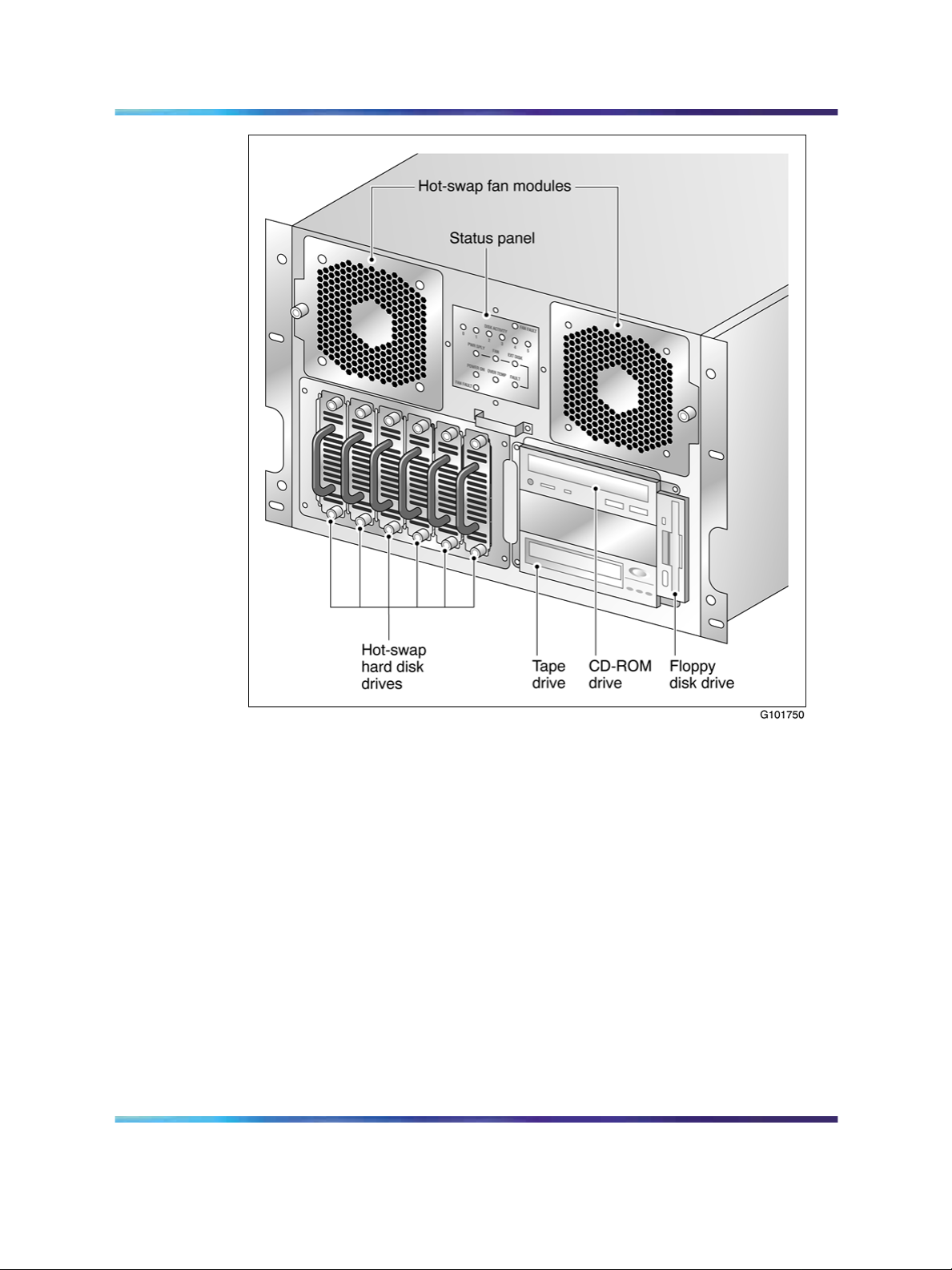
Front panel features (front view without the front bezel)
The front view of the 1002rp server chassis shows redundant dual fans to
the left and the right of the status panel. The left drive bay holds six SCSI
hard drives with hot-pluggable carriers. The media drive bay, located to the
right, houses the CD-ROM, tape drive, and floppy disk drive.
Cto25
C (86F)
C [64.4
Fto
C
1002rp Server Hardware Installation
NN44200-300 01.01 Standard
Copyright © 2007, Nortel Networks Nortel Networks Confidential
.
Nortel CallPilot
5.0 23 February 2007
Page 13
Server features 13
Alarm board
The alarm board is located under the baseboard. It connects to the status
display panel on the front.
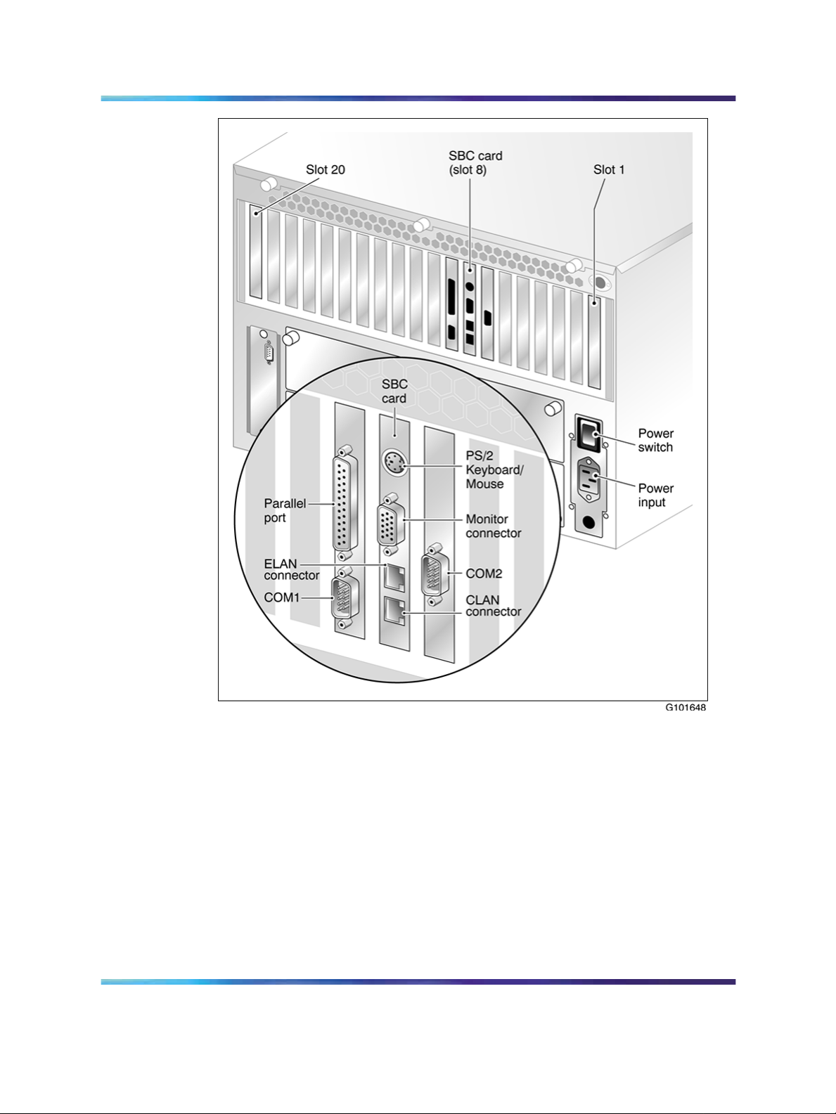
Rear panel diagram
The following diagram shows the slot locations in the rear panel, and the
power switch and power input for an AC server. The rest of the diagram
is the same for AC or DC servers.
1002rp Server Hardware Installation
NN44200-300 01.01 Standard
Copyright © 2007, Nortel Networks Nortel Networks Confidential
.
Nortel CallPilot
5.0 23 February 2007
Page 14
14 Chapter 2 1002rp server description
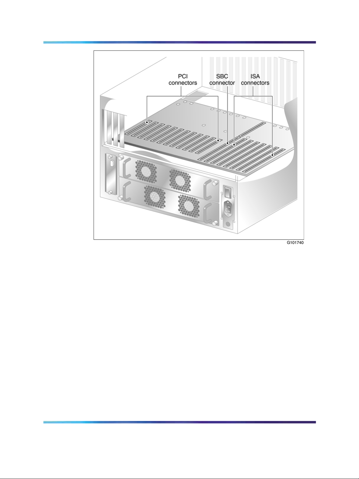
Overhead view of empty server showing PCI and ISA connectors
The following diagram shows the location of the PCI, SBC, and ISA
connectors inside the server. The view in the diagram is from the rear of the
server. For slot assignments, see "Slot assignments" (page 15). You must
be able to identify slot locations for later steps in the CallPilot installation.
1002rp Server Hardware Installation
NN44200-300 01.01 Standard
Copyright © 2007, Nortel Networks Nortel Networks Confidential
.
Nortel CallPilot
5.0 23 February 2007
Page 15
Slot assignments 15
Slot assignments
Introduction
The slot assignment tables show the following:
•
the physical location of boards inside the server, relative to other boards
•
the order in which boards are installed (for example, board #1, 2, 3)
•
how the boards are represented in some CallPilot Manager applications
(such as the Maintenance Administration page)
•
the maximum capacity for each switch connectivity
Note: Your server can vary depending on what was ordered from
Nortel. Therefore, your server may not have all of the slots populated.
Reference Documents
For a list of all CallPilot documents, see the following CallPilot Customer
Documentation Map.
1002rp Server Hardware Installation
NN44200-300 01.01 Standard
Copyright © 2007, Nortel Networks Nortel Networks Confidential
.
Nortel CallPilot
5.0 23 February 2007
Page 16
16 Chapter 2 1002rp server description
1002rp Server Hardware Installation
Nortel CallPilot
NN44200-300 01.01 Standard
Copyright © 2007, Nortel Networks Nortel Networks Confidential
.
5.0 23 February 2007
Page 17

Slot assignments 17
Slot definition and slot numbering
In these tables, the term slot refers to the available slot openings in the
chassis, not the PCI or ISA connectors inside the server.
Look at the server from the rear (see "Rear panel diagram" (page 13)). The
slots are numbered from right to left, 1 to 20. Now, look at the server from
the front. The slots are numbered from left to right.
Note: For Meridian 1 and Communication Server 1000, the first
MPB16-4 board must be installed in slot 11. You can install up to a
maximum of two MPB16-4 boards.
1002rp slot assignments
Meridian 1*/
Communication
Slot
number
CallPilot-assigned
board label
a
Slot 1 BRD01 Not used Not used
Slot 2 BRD02 Not used Not used
Server*
1000 T1/SMDI
Slot 3 BRD03 Not used Not used
Slot 4 BRD04 Not used Not used
Slot 5 BRD05 Not used Not used
Slot 6 BRD06 Not used Not used
Slot 7 BRD07 Reserved for COM2
I/O bracket
b
Slot 8
BRD08 Single board
computer
Slot 9 (PCI Slot 1) BRD09 Reserved for COM1
and parallel port I/O
bracket
Reserved for COM2
I/O bracket
Single board
computer
Reserved for COM1
and parallel port I/O
bracket
Slot 10 (PCI Slot 2) BRD10 PCI RAID controller PCI RAID controller
Slot 11 (PCI Slot 3) BRD11 MPB16-4 #1 or
MPB96 board #1
MPB96 #1
Slot 12 (PCI Slot 4) BRD12 MPB16-4 #2
D/480JCT-2T1
(optional)
a. On some CallPilot Manager screens, the CallPilot-assigned board label is displayed. This label
corresponds to the slot number. For example, BRD12 refers to the board in slot 12.
b. The SBC card includes two onboard NICs (for connection to the ELAN subnet, and the Nortel
server subnet) and an onboard video card. The NIC and monitor connectors are on the SBC
faceplate.
1002rp Server Hardware Installation
NN44200-300 01.01 Standard
Copyright © 2007, Nortel Networks Nortel Networks Confidential
.
Nortel CallPilot
5.0 23 February 2007
Page 18
18 Chapter 2 1002rp server description
Slot
number
CallPilot-assigned
board label
a
Meridian 1*/
Communication
Server*
1000 T1/SMDI
Slot 13 (PCI Slot 5) BRD13 MPB16-4 #2
D/480JCT-2T1
(optional)
Slot 14 (PCI Slot 6) BRD14 MPB16-4 #2
(optional) or MPB96
MPB96 board #2
(optional)
#2 (optional)
Slot 15 (PCI Slot 7) BRD15 MPB16-4 #2
(optional)
Slot 16 (PCI Slot 8) BRD16 MPB16-4 #2
(optional)
Slot 17 (PCI Slot 9) BRD17 MPB16-4 #2
D/480JCT-2T1
(optional)
D/480JCT-2T1
(optional)
MPB96 #3 (optional)
(optional) or MPB96
#3 (optional)
Slot 18 (PCI Slot
10)
Slot 19 (PCI Slot
BRD18 MPB16-4 #2
Not used
(optional)
BRD19 Not used Not used
11)
Slot 20 (PCI Slot
BRD20 Not used Not used
12)
a. On some CallPilot Manager screens, the CallPilot-assigned board label is displayed. This label
corresponds to the slot number. For example, BRD12 refers to the board in slot 12.
b. The SBC card includes two onboard NICs (for connection to the ELAN subnet, and the Nortel
server subnet) and an onboard video card. The NIC and monitor connectors are on the SBC
faceplate.
Network connectivity
Introduction
This section describes how the 1002rp server can be integrated into your
network. The integration depends on the type of switch you are using.
ATTENTION
To secure the CallPilot server from unauthorized access, ensure that the CallPilot
network is inside your organization’s firewall.
1002rp Server Hardware Installation
NN44200-300 01.01 Standard
Copyright © 2007, Nortel Networks Nortel Networks Confidential
.
Nortel CallPilot
5.0 23 February 2007
Page 19
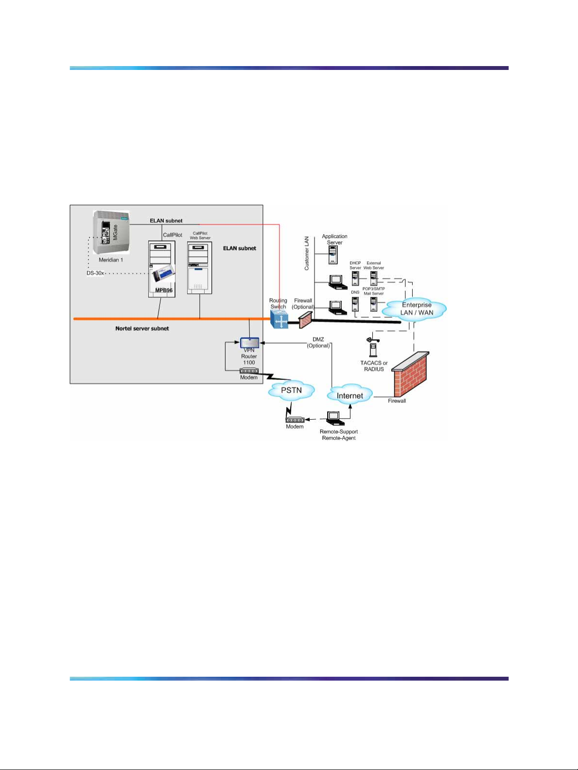
Sample network setup: Meridian 1
The following diagram shows a CallPilot server sample network setup with a
Meridian 1 switch. The Meridian 1 switch can be one of the following:
•
Option 11C or Option 11C Mini
•
Option 51C
•
Option 61C
•
Options 81 and 81C
Network connectivity 19
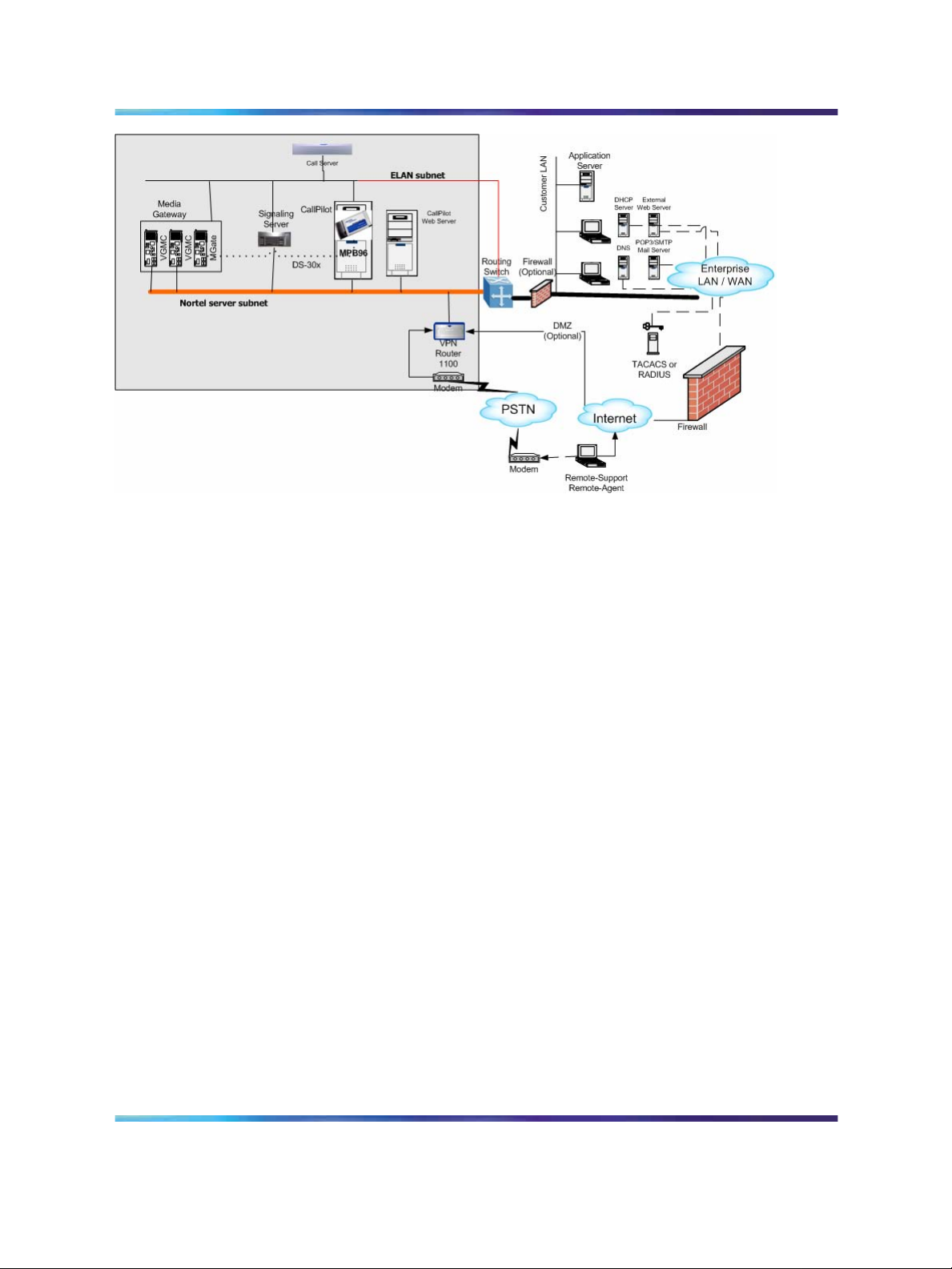
Sample network setup: Communication Server 1000
The following diagram shows a CallPilot server network setup with a
Communication Server 1000 system.
1002rp Server Hardware Installation
NN44200-300 01.01 Standard
Copyright © 2007, Nortel Networks Nortel Networks Confidential
.
Nortel CallPilot
5.0 23 February 2007
Page 20
20 Chapter 2 1002rp server description
Switch connectivity
For more details about how the 1002rp server and switch connection
is established, refer to the Installation and Configuration Task List
(NN44200-306).
CallPilot ELAN subnet and Nortel server subnet setup
The 1002rp server provides 10/100Base-T Ethernet connectivity through
NICs installed in the server. See "Slot assignments" (page 15) for details
on the location of NICs. The function of the NIC varies based on switch
connectivity, as described below:
Meridian 1 or Communication Server 1000 systems
•
One NIC provides connectivity to the ELAN subnet.
For information about the purpose and requirements of the ELAN, see
the Planning and Engineering Guide (NN44200-200).
•
A second NIC is optional.
This optional NIC is required only for Meridian 1 or Communication
Server 1000 systems that require a connection to the Nortel server
subnet (in addition to the ELAN subnet connection). The Nortel server
subnet provides data connectivity between desktop and Web messaging
clients, Web-enabled administrative PCs, and the CallPilot server.
Network requirements
Appropriate networking equipment must be available for both the Nortel
server subnet and ELAN subnet.
1002rp Server Hardware Installation
NN44200-300 01.01 Standard
Copyright © 2007, Nortel Networks Nortel Networks Confidential
.
Nortel CallPilot
5.0 23 February 2007
Page 21

Supported peripheral devices 21
The Nortel server subnet and ELAN subnet must be properly configured
for correct CallPilot operation. To ensure correct configuration, Nortel
recommends that you consult a network specialist.
Remote access connectivity
The RS-232 COM1 connector on the rear of the 1002rp server provides
the connection to an external modem. The modem allows administrators
and technical support personnel to administer the 1002rp server from a
remote location.
pcAnywhere is used to establish the remote access connection to the server.
Supported peripheral devices
Introduction
This section identifies external devices that are supported by the 1002rp
server.
Device Description
Modem A 56-Kbit/s external modem (NTRH9078) provides remote access
to the 1002rp server. The modem connects to the RS-232 COM1
connector on the rear of the server.
Ethernet hub or switch
Since the modem is an external device, it requires its own AC power
source referenced to the same ground as the 1002rp server and the
switch to which it is connected.
A 10Base-T Ethernet hub or switch provides the ELAN subnet
connection between the 1002rp server and the Meridian 1 switch
or Communication Server 1000 system. The customer can
supply an ethernet hub or switch from third-party vendors or from
Nortel.
Since the ethernet hub or switch is an external device, it requires
an AC power source.
ATTENTION
To comply with EMC radiation requirements, a Class A hub
must be located 10 m (33 ft) away from the 1002rp server.
Shielded Ethernet cables must be used.
1002rp Server Hardware Installation
NN44200-300 01.01 Standard
Copyright © 2007, Nortel Networks Nortel Networks Confidential
.
Nortel CallPilot
5.0 23 February 2007
Page 22

22 Chapter 2 1002rp server description
Device Description
•
Monitor, keyboard, and
mouse
15-in. monitor: NTRH9011 or N0038380 LCD monitor.
Since the monitor is an external device, it requires its own AC
power source.
•
Keyboard: NTRH9013
•
Mouse: NTRH9014
1002rp Server Hardware Installation
NN44200-300 01.01 Standard
Copyright © 2007, Nortel Networks Nortel Networks Confidential
.
Nortel CallPilot
5.0 23 February 2007
Page 23

Chapter 3
Preparing for installation
In this chapter
"Installation overview" (page 23)
"Unpacking the 1002rp server" (page 26)
"Removing the front bezel and server cover" (page 27)
"Inspecting the server interior" (page 29)
Installation overview
Introduction
This section provides an overview of the steps required to install the 1002rp
server and peripheral devices.
23
Installation checklist
The following checklist identifies the tasks that must be performed when
installing the CallPilot server. For detailed instructions, see "Installing the
server" (page 43) When you are finished with the installation, continue with
the Installation and Configuration Task List (NN44200-306).
Step
1
Copyright © 2007, Nortel Networks Nortel Networks Confidential
.
Description
Ensure that you have reviewed the "Installing the CallPilot server" section in
the Installation and Configuration Task List (NN44200-306), and completed
stage 1 of the "Installation checklist."
Nortel CallPilot
1002rp Server Hardware Installation
NN44200-300 01.01 Standard
5.0 23 February 2007
Check
Page 24

24 Chapter 3 Preparing for installation
Step
2
3
4
5
6
7
Description
Unpack the server, and ensure you have all the items you need (see
"Unpacking the 1002rp server" (page 26)).
Complete the following checklists that are provided in the Installation and
Configuration Task List (NN44200-306):
• "CallPilot software media and documentation checklist"
•
"CallPilot server hardware checklist"
Remove the front bezel and server cover, and inspect the interior (see pages
"Removing the front bezel and server cover" (page 27) and "Inspecting the
server interior" (page 29)).
Replace the server cover.
Install the power supply modules in the server (see "Installing the second
power supply module (AC or DC)" (page 34)).
For a DC-powered server, set up the DC power source (see "DC wire gauge
tables" (page 36)).
Place the 1002rp server in the chosen location (see "Installing the server"
(page 43)).
Check
8
9
10
Replace the front bezel (see page "Inspecting the server interior" (page 29)).
Set the DIP switches on the modem (see "Preparing the modem" (page 44)).
Connect the 1002rp server and devices as follows:
•
Connect the monitor, keyboard, and mouse (see "Connecting peripherals to
the server" (page 47)).
•
Connect the modem (see "Preparing the modem" (page 44)).
•
Connect the 1002rp server to the ELAN hub or switch (Meridian 1 or
Communication Server 1000 only) (see "Connecting the server to the ELAN
subnet" (page 49)).
ATTENTION
To comply with EMC radiation requirements, a Class A hub must be
located 10 m (33 ft.) away from the 1002rp server. Shielded Ethernet
cables must be used.
1002rp Server Hardware Installation
NN44200-300 01.01 Standard
Copyright © 2007, Nortel Networks Nortel Networks Confidential
.
Nortel CallPilot
5.0 23 February 2007
Page 25

Installation overview 25
Step
Description
Note: If you are connecting the optional Nortel server subnet, do not power up
unless your antivirus programs and Nortel security updates are installed first.
•
Connect the 1002rp server to the CLAN hub or switch (optional) (see
"Connecting the server to the Nortel server subnet (optional)" (page 51)).
ATTENTION
To comply with EMC radiation requirements, a Class A hub must be
located 10 m (33 ft.) away from the 1002rp server. Shielded Ethernet
cables must be used.
•
Install the software feature dongle (see "Installing the Nortel software feature
dongle" (page 52)).
Check
11
•
Connect the power cords for all devices, and then power them up.
Start the 1002rp server (see "Connecting the server to power" (page 53)).
Conventions for warnings
You may encounter the following types of warnings in this guide. Do not
ignore them.
DANGER
Warns you of an immediate electrical hazard which, if not avoided,
can result in shock, serious injury, or death.
WARNING
Warns you of a situation in which you can be injured if instructions
are not followed exactly as stated.
1002rp Server Hardware Installation
NN44200-300 01.01 Standard
Copyright © 2007, Nortel Networks Nortel Networks Confidential
.
Nortel CallPilot
5.0 23 February 2007
Page 26

26 Chapter 3 Preparing for installation
CAUTION
Alerts you to situations where data can be lost or damaged,
equipment can be damaged, actions can result in service
interruption, and productive time can be lost.
Provides information that is essential to the completion of a task.
Unpacking the 1002rp server
Introduction
Follow this procedure to unpack the server and peripherals.
WARNING
The 1002rp CallPilot server weighs approximately 34 kg (75 lb)
as shipped from manufacturing. To prevent personal injury, have
someone help you to unpack and position the server.
ATTENTION
To unpack the equipment
Step Action
ATTENTION
As you unpack each item, check it off against the packing list, as well as against
the following checklists provided in the Installation and Configuration Task List
(NN44200-306):
•
"CallPilot software media and documentation checklist"
•
"CallPilot server hardware checklist"
1
2
3
4
5
Carefully open the cardboard carton containing the server.
Remove the server from the carton; set it on the floor.
Carefully open the cartons containing the monitor, keyboard, mouse,
modem, and ELAN hub (if supplied), and set the peripherals aside.
Put all manuals, CD-ROMs, operating system disks, and any disks
for peripherals in a safe place.
Save all packing materials and cartons in case you must return any
equipment to the carrier.
—End—
1002rp Server Hardware Installation
NN44200-300 01.01 Standard
Copyright © 2007, Nortel Networks Nortel Networks Confidential
.
Nortel CallPilot
5.0 23 February 2007
Page 27

Removing the front bezel and server cover 27
What is next?
Remove the server cover so that you can inspect the interior of the server.
See "Removing the front bezel and server cover" (page 27).
Removing the front bezel and server cover
Introduction
To access the server interior, you must remove both the front bezel and
the server cover.
Two locked doors, located on the front of the server, cover the front panel,
including the CD-ROM drive and tape drive. These doors are part of the
front bezel. You must unlock the front bezel doors before you can remove
the bezel.
To remove the front bezel
Step Action
CAUTION
Do not attempt to move or lift the server before removing the front
bezel; the server can disengage from the bezel and fall.
1
Unlock and open the double doors of the front bezel. See A in the
diagram below.
2 Firmly grasp the front bezel by the hand-holds on either side of the
chassis, and pull the front bezel from the chassis.
1002rp Server Hardware Installation
NN44200-300 01.01 Standard
Copyright © 2007, Nortel Networks Nortel Networks Confidential
.
Nortel CallPilot
5.0 23 February 2007
Page 28

28 Chapter 3 Preparing for installation
To remove the server cover
Step Action
DANGER
High current inside the chassis can cause severe injury.
CAUTION
Take precautions to protect internal components. Electrostatic
discharge (ESD) can render boards damaged or unusable. Wear
an ESD wrist strap.
1
Remove the front bezel (see "To remove the front bezel" (page 27)).
—End—
1002rp Server Hardware Installation
NN44200-300 01.01 Standard
Copyright © 2007, Nortel Networks Nortel Networks Confidential
.
Nortel CallPilot
5.0 23 February 2007
Page 29

Inspecting the server interior 29
2
3
Loosen the three thumbscrews at the rear of the top cover.
Remove the server cover by pulling the cover toward the rear of the
chassis, and then lifting it up and off.
4
Clip the lead from your ESD wrist strap to an unpainted metal section
of the chassis.
What is next?
Continue with "Inspecting the server interior" (page 29).
Inspecting the server interior
Introduction
You should perform a visual inspection for loose components, foreign matter,
or shipping damage inside the server.
CAUTION
When working with interior components, use an ESD wrist strap to
protect static-sensitive components.
—End—
To inspect the server interior
Step Action
1 Carefully check all the cards to ensure they are fully seated on the
baseboard.
2
3 Review the slot locations (see "Slot assignments" (page 15)).
4
Copyright © 2007, Nortel Networks Nortel Networks Confidential
.
Check for any loose wires or foreign objects, such as loose screws,
inside the chassis.
Do one of the following:
IF THEN
you observe any damage contact your Nortel technical
support representative.
Nortel CallPilot
1002rp Server Hardware Installation
NN44200-300 01.01 Standard
5.0 23 February 2007
Page 30

30 Chapter 3 Preparing for installation
IF THEN
components have become loose secure them.
Refer to the procedures in the
Installation and Configuration
Task List (NN44200-306).
you are satisfied that the 1002rp
server has arrived at your site
undamaged
replace the server cover and
proceed with the hardware
installation.
See "Installation checklist" (page
23).
Note: Do not reinstall the front
bezel until the server is in its
final location and the CallPilot
installation is complete.
—End—
To replace the front bezel after installation is complete
Step Action
When the CallPilot server installation is complete and the server is in its
final location, replace the front bezel.
1
Align the front bezel with the ball studs located at each faceplate
corner.
See the diagram below:
1002rp Server Hardware Installation
NN44200-300 01.01 Standard
Copyright © 2007, Nortel Networks Nortel Networks Confidential
.
Nortel CallPilot
5.0 23 February 2007
Page 31

Inspecting the server interior 31
2
3
Apply pressure evenly until the bezel snaps onto each ball stud.
Close and lock the double doors of the front bezel.
—End—
1002rp Server Hardware Installation
NN44200-300 01.01 Standard
Copyright © 2007, Nortel Networks Nortel Networks Confidential
.
Nortel CallPilot
5.0 23 February 2007
Page 32

32 Chapter 3 Preparing for installation
1002rp Server Hardware Installation
Nortel CallPilot
NN44200-300 01.01 Standard
Copyright © 2007, Nortel Networks Nortel Networks Confidential
.
5.0 23 February 2007
Page 33

Chapter 4
Power supply installation
In this chapter
"Safety precautions" (page 33)
"Installing the second power supply module (AC or DC)" (page 34)
"DC wire gauge tables" (page 36)
"DC rack cabling" (page 37)
"About the power distribution unit" (page 40)
"Bringing power and ground into the PDU" (page 42)
33
Safety precautions
Equipment handling guidelines
External power equipment, such as an uninterruptible power supply (UPS),
is usually very heavy. This equipment requires special handling procedures
and additional personnel for unloading and installation. Be aware of weight
distribution, and prevent the equipment room floor from being overly
stressed.
Safety information
In DC systems, locate the service panel near the entry to the room
containing the DC power system that supplies the server.
DANGER
Procedures involving electrical connections must be performed
only by qualified personnel.
Ensure that you obey all displayed warning notices on power
equipment and connections.
1002rp Server Hardware Installation
NN44200-300 01.01 Standard
Copyright © 2007, Nortel Networks Nortel Networks Confidential
.
Nortel CallPilot
5.0 23 February 2007
Page 34

34 Chapter 4 Power supply installation
Installing the second power supply module (AC or DC)
Introduction
One power supply module is shipped installed. The second power supply
module must be installed on-site.
AC versus DC systems
The power supply modules are similar in appearance for both AC and DC
1002rp servers. The procedures in this section apply to both AC and DC
1002rp servers.
About the power supply module
After the server is powered up (later in this guide), the power supply module
LED indicates its status.
A green LED on the power supply module indicates that the module is
working properly. If the LED is unlit or red, the module is failing or has failed.
A problem with the power supply module is also indicated if an alarm sounds
or the power supply LED on the front of the server turns red.
The diagram below shows the location of the power supply modules in a
server that has two power supply modules installed:
1002rp Server Hardware Installation
NN44200-300 01.01 Standard
Copyright © 2007, Nortel Networks Nortel Networks Confidential
.
Nortel CallPilot
5.0 23 February 2007
Page 35

Installing the second power supply module (AC or DC) 35
To install the power supply module
DANGER
High current inside the chassis can cause severe injury.
The server is shipped with one power supply module installed in the bottom
power supply bay. You must install the second power supply module, as
described here:
Step Action
1
2
Copyright © 2007, Nortel Networks Nortel Networks Confidential
.
Align the power supply module with the top power supply bay.
Slide the power supply module into the bay until the module is
secured by its connector.
Use some force, if necessary.
Nortel CallPilot
1002rp Server Hardware Installation
NN44200-300 01.01 Standard
5.0 23 February 2007
Page 36

36 Chapter 4 Power supply installation
3
Secure the power supply module to the chassis with two
thumbscrews at the corners of the power supply faceplate.
What is next?
Do one of the following:
IF THEN
this is an AC-powered server
this is a DC-powered server
DC wire gauge tables
Introduction
The tables in this section specify the DC power feed wire requirements.
Cabinet and module DC feed recommended wire gauge specifications
—End—
continue with "Installing the server"
(page 43) on page "Installing the
server" (page 43).
continue with "DC wire gauge tables"
(page 36).
Junction
box #4
Length #10 AWG #8 AWG #6 AWG
0-30 m (100 ft)
0-45 m (150 ft)
0-75 m (250 ft)
0-135 m (450 ft)
Notes:
1.
The cabinet and module ground wire specification is #10 AWG insulated green safety ground wire.
2.
The cabinet conduit can be 19.1 mm (0.75-in.) or 31.8 mm (1.25-in.), and must be insulated
from the cabinet ground.
yes yes yes yes yes
no yes yes yes yes
no no yes yes yes
no no no yes yes
AWG
Junction
box #4
AWG
1002rp Server Hardware Installation
NN44200-300 01.01 Standard
Copyright © 2007, Nortel Networks Nortel Networks Confidential
.
Nortel CallPilot
5.0 23 February 2007
Page 37

DC rack cabling 37
Length #10 AWG #8 AWG #6 AWG
0-210 m (700 ft)
Over 210 m (700 ft)
no no no no yes
no no no no no
Junction
box #4
AWG
Junction
box #4
AWG
Notes:
1.
The cabinet and module ground wire specification is #10 AWG insulated green safety ground wire.
2.
The cabinet conduit can be 19.1 mm (0.75-in.) or 31.8 mm (1.25-in.), and must be insulated
from the cabinet ground.
Metric wire conversion
Industry standard
AWG No.
nominal (sq mm)
2 35 0.05
Resistance at 20 C
(Ohm/100 m)
4 25 0.08
6 16 0.13
8 10 0.20
10 6 0.33
12 4 0.63
14 2.5 1.00
16 1.5 1.40
18 1 2.00
20 0.75 2.90
22 0.5 4.60
DC rack cabling
The following photograph shows typical rack power cabling:
1002rp Server Hardware Installation
NN44200-300 01.01 Standard
Copyright © 2007, Nortel Networks Nortel Networks Confidential
.
Nortel CallPilot
5.0 23 February 2007
Page 38

38 Chapter 4 Power supply installation
Note: The cables are marked with Red and Green tape. The cables
with the Red tape connect to the Negative (-) Red side (on the left in the
photograph), and the cables with the Green tape connect to the Positive
(+) Green side (on the right in the photograph). The sides are identified
on the power connections. The ground wire enters at the lower right and
attaches to the ground lug.
Main panel wiring diagram with product number.
1002rp Server Hardware Installation
NN44200-300 01.01 Standard
Copyright © 2007, Nortel Networks Nortel Networks Confidential
.
Nortel CallPilot
5.0 23 February 2007
Page 39

DC rack cabling 39
Rack power and grounding
To ensure a complete power and grounding installation:
•
In rackmount server installations, ensure the CallPilot server chassis
and equipment racks are isolated from other foreign sources of ground.
Acceptable isolation methods include: isolation pads, grommeted
washers, chassis side rail strips, and non-conducting washers.
•
In rackmount server installations where other equipment is also installed
in the same 19" rack, ensure that all equipment derives ground from
1002rp Server Hardware Installation
NN44200-300 01.01 Standard
Copyright © 2007, Nortel Networks Nortel Networks Confidential
.
Nortel CallPilot
5.0 23 February 2007
Page 40

40 Chapter 4 Power supply installation
the same service panel as CallPilot and the switch, whether or not the
equipment is AC- or DC-powered.
-48 V DC power distribution rationale
•
Minimum installation is one power distribution unit (PDU) with four 48 V
DC branch circuits fused at 20 amperes.
•
The customer must be able to shut off any branch to ensure every unit
at the site continues to function properly.
• DC-powered configuration fits into this scheme as follows:
— Each PDU receives four branch circuits.
— Each server receives a feed from each PDU and a different branch
circuit.
•
In this fashion, with dual hot-swappable power supplies, there is no
single point of failure in the power system. For example, you can remove
any power supply, including a PDU, and everything continues to work.
•
This is applicable to either North American or European installation
sites (with a 230 V AC inverter).
•
The secondary rack supports four servers and follows a similar scheme.
About the power distribution unit
Introduction
A PDU is installed in a rack that has DC-powered servers. Power from
the DC supply source enters the PDU and can then be distributed to one
or more servers. A single PDU can supply DC power to four DC power
supply modules. A server can have either one or two power supply modules
installed. You can determine the number of PDUs to install in a rack by
counting the number of power supply modules in each rack.
PDU power and grounding
To ensure a complete power and grounding installation:
•
In rackmount DC-powered server installations, ensure the PDU (Power
Distribution Unit for DC applications) is installed on the same rack as
the CallPilot server. This is required since the main ground wire for the
PDU is not insulated from the metal enclosure.
Multiple PDUs
A server operates on a single power supply module. Its total capacity is
two installed power supply modules. The second power supply module is
the redundant power supply module.
1002rp Server Hardware Installation
NN44200-300 01.01 Standard
Copyright © 2007, Nortel Networks Nortel Networks Confidential
.
Nortel CallPilot
5.0 23 February 2007
Page 41

A PDU can distribute power to a maximum of four power supply units that
can be installed in two or more servers. Therefore, if there are three or four
servers installed in a rack, then you must install a second PDU.
Note: The power supply module installs in the server. It does not refer
to a UPS, which is a separate unit on the rack.
PDU terminal blocks and wiring diagram
A PDU consists of eight terminal blocks within a metal enclosure. Before
installing the PDU, connect the terminal blocks so that each output
connector receives power from a separate -48 V dc branch circuit, as shown
in the following diagram. Use AWG 10 wires for these connections.
Single PDU wiring diagram
About the power distribution unit 41
DC power input
DC power input into the distribution unit connects BAT-1 to BAT-4 and BR-1
to BR-4. Refer to the preceding diagrams for the location of these terminals.
Connect the input wires before installing the PDU on the rack.
1002rp Server Hardware Installation
NN44200-300 01.01 Standard
Copyright © 2007, Nortel Networks Nortel Networks Confidential
.
Nortel CallPilot
5.0 23 February 2007
Page 42

42 Chapter 4 Power supply installation
Bringing power and ground into the PDU
Introduction
Install BAT/BATRTN wires in pairs. Each pair of wires supplies voltages to a
module through a power harness. The module harnesses are installed in
the cabinet PDU and connected to the modules at the factory. See "About
the power distribution unit" (page 40).
To bring DC power and ground into the PDU
Step Action
1
If you are using a conduit, terminate the 32 mm (1-1/4 in.) or 19 mm
(3/4 in.) conduit at the top rear of the cabinet or at the bottom front of
the cabinet using the knockouts provided. The number of wire pairs
you can run in each conduit depends on the wire gauge.
Note: To preserve ground integrity, the conduit must be
insulated.
2
Select a power feed with a circuit breaker dedicated to each module,
and identify it with an appropriate tag.
3
Select a wire size to suit the required feed length from the power
source (see "DC wire gauge tables" (page 36)).
4
Use pliers to strip 6 mm (1/4 in.) to 13 mm (1/2 in.) of the insulation
from one end of all power and ground feed wires.
5
6
7
8
9
Undo the terminal block screws at (-) positions 0, 1, 2, and 3.
Insert the red wires into terminal block positions 0, 1, 2, and 3.
Secure the wires in the terminal block by tightening the screws.
Undo the terminal block screws at (+) positions 0, 1, 2, and 3.
Insert the black wires into terminal block positions 0, 1, 2, and 3.
10
11
Secure the wires in the terminal block by tightening the screws.
Select a #10 AWG green wire safety ground and attach it to the
cabinet.
12 Measure the module ground continuity by touching one multimeter
lead to any BATRTN terminal block connector and the other end
to the GND terminal block connector. Ensure the measurement is
between 0-0.5 ohms.
—End—
1002rp Server Hardware Installation
NN44200-300 01.01 Standard
Copyright © 2007, Nortel Networks Nortel Networks Confidential
.
Nortel CallPilot
5.0 23 February 2007
Page 43

43
Chapter 5
Installing the server and connecting the
peripheral devices
In this chapter
"Installing the server" (page 43)
"Preparing the modem" (page 44)
"Connecting peripherals to the server" (page 47)
"Connecting the server to the ELAN subnet" (page 49)
"Connecting the server to the Nortel server subnet (optional)" (page 51)
"Installing the Nortel software feature dongle" (page 52)
"Connecting the server to power" (page 53)
Installing the server
Introduction
Before you install the 1002rp server, ensure that the chosen location meets
the requirements identified on the "Site inspection checklist" provided in the
Installation and Configuration Task List (NN44200-306).
To install the server
Place the 1002rp serverin its chosen location. If you are installing the server
in a rack cabinet, follow the instructions that are provided with the slide rails.
Connect peripheral devices as described in the remainder of this chapter.
1002rp Server Hardware Installation
NN44200-300 01.01 Standard
Copyright © 2007, Nortel Networks Nortel Networks Confidential
.
Nortel CallPilot
5.0 23 February 2007
Page 44

44 Chapter 5 Installing the server and connecting the peripheral devices
WARNING
Do not connect the server to the power yet.
Preparing the modem
Introduction
You require a modem to support remote dial-up access to the CallPilot
server. The modem also enables Nortel technical support to connect to
your CallPilot server for troubleshooting purposes. Nortel connects to your
server only when you request technical assistance.
Required equipment
To install the modem, you need the following equipment:
•
an RJ-11 analog phone cord
•
a power adapter cord
•
an analog line jack
•
tweezers, or a screwdriver small enough to use to adjust DIP switches
The following modem is provided with your server:
•
an analog external U.S. Robotics 56-Kbit/s modem (NTRH9078) that
includes a 25-pin male to 9-pin female shielded serial cable for your
modem
Note: Ensure that you have the correct cable for your modem, as
follows:
— 56-Kbit/s modem: A0841984
Modem DIP switches
Set the modem DIP switches before you connect the modem to the CallPilot
server.
Note: This section applies only to the U.S. Robotics 56-Kbit/s external
Sportster modem. If your modem is different, refer to the documentation
for your modem.
The following diagram shows the key components of the external modem,
including the location and required settings of the DIP switches:
1002rp Server Hardware Installation
NN44200-300 01.01 Standard
Copyright © 2007, Nortel Networks Nortel Networks Confidential
.
Nortel CallPilot
5.0 23 February 2007
Page 45

Preparing the modem 45
DIP
switch
1
2
3
To set the modem DIP switches
Use a pair of tweezers or a small screwdriver to set the DIP switches as
described in the Change to column of the following table:
Note: ON is down. OFF is up.
Default
setting
OFF OFF Data Terminal Ready (DTR) override
OFF OFF Verbal/numeric result codes
ON ON Result code display
Change
to Function
•
OFF: Normal DTR operations. (The computer
must provide a DTR signal for the modem to
accept commands. If DTR is dropped, the call is
terminated.)
•
ON: The modem ignores DTR (override).
•
OFF: Verbal (word) results.
•
ON: Numeric results.
•
OFF: Suppresses result codes.
• ON: Enables result codes.
1002rp Server Hardware Installation
NN44200-300 01.01 Standard
Copyright © 2007, Nortel Networks Nortel Networks Confidential
.
Nortel CallPilot
5.0 23 February 2007
Page 46

46 Chapter 5 Installing the server and connecting the peripheral devices
DIP
switch
4
5
6
7
Default
setting
Change
to Function
OFF OFF Command mode local echo suppression
•
OFF: Displays keyboard commands.
•
ON: Suppresses echo.
ON ON Auto answer suppression
• OFF: The modem answers on the first ring, or
higher if specified in NVRAM.
• ON: Disables auto answer.
OFF OFF Carrier Detect (CD) override
•
OFF: The modem sends a CD signal when it
connects with another modem; it drops the CD on
disconnect.
•
ON: CD is always ON (override).
OFF OFF Power-on and ATZ reset software defaults
•
OFF: Loads Y or Y1 configuration from user-defined
NVRAM.
•
ON: Loads &F0-Generic template from read-only
memory (ROM).
8
ON ON AT command set recognition
•
OFF: Disables command recognition (dumb mode).
• ON: Enables recognition (smart mode).
What is next?
Continue with "Connecting peripherals to the server" (page 47).
1002rp Server Hardware Installation
NN44200-300 01.01 Standard
Copyright © 2007, Nortel Networks Nortel Networks Confidential
.
Nortel CallPilot
5.0 23 February 2007
Page 47

Connecting peripherals to the server
Rear panel connectors
Connecting peripherals to the server 47
Note: The above diagram shows the power switch and power input
for an AC server. The rest of the diagram is the same for AC or DC
servers. For peripheral device connections, this picture applies to AC
and DC servers.
To connect the mouse, keyboard, and monitor to the server
Step Action
1 Place the monitor, keyboard, and mouse in the same location as
the server.
1002rp Server Hardware Installation
NN44200-300 01.01 Standard
Copyright © 2007, Nortel Networks Nortel Networks Confidential
.
Nortel CallPilot
5.0 23 February 2007
Page 48

48 Chapter 5 Installing the server and connecting the peripheral devices
2
Plug the keyboard/mouse dual cable into the PS/2 connector on the
SBC card faceplate (see "Rear panel connectors" (page 47)).
3
Plug the keyboard and mouse into the appropriate connectors on
the keyboard/mouse dual cable.
4
Plug the monitor into the monitor connector on the SBC card.
Tighten the screws on the connector.
5
Ensure that a single-point ground reference is available for all
the power outlets serving the CallPilot server and its peripherals.
Before the CallPilot server installation, a qualified electrician must
implement the single-point ground reference requirement between
the power outlets of the CallPilot server and the power outlets of
the switch.
6
Connect the power cord to the monitor and plug the other end into
a wall receptacle or power bar.
Note: Ensure that the power source is consistent with the SBC
for all ancillary equipment.
7
Turn on the monitor.
—End—
To connect the modem to the server
Step Action
1
2
3
4
5
6
Ensure that the modem AC power cord is not plugged in.
Connect the large 25-pin male connector to the back of the modem.
Tighten the connector screws.
Connect the 9-pin female connector to COM1 at the rear of the
server. Tighten the connector screws.
Connect one end of the telephone cable to the modem RJ-11 jack
labeled LINE.
Connect the other end of the telephone cable to the RJ-11 jack in
the wall.
Ensure that a single-point ground reference is available for all
the power outlets serving the CallPilot server and its peripherals.
Before the CallPilot server installation, a qualified electrician must
implement the single-point ground reference requirement between
1002rp Server Hardware Installation
NN44200-300 01.01 Standard
Copyright © 2007, Nortel Networks Nortel Networks Confidential
.
Nortel CallPilot
5.0 23 February 2007
Page 49

Connecting the server to the ELAN subnet 49
the power outlets of the CallPilot server and the power outlets of
the switch.
7
Connect the power cord to the modem, and plug the other end into
a wall receptacle or power bar.
Note: Ensure that the power source is consistent with the SBC
for all ancillary equipment.
8
Turn on the modem.
—End—
What is next?
Continue with "Connecting the server to the ELAN subnet" (page 49).
Connecting the server to the ELAN subnet
Introduction
ATTENTION
This section applies only if the 1002rp server connects to a Meridian 1 switch or
Communication Server 1000 system.
Connect the CallPilot server to the Meridian 1 switch or Communication
Server 1000 system using the ELAN interface.
ATTENTION
For important considerations about using the ELAN subnet in your network, see
the CallPilot Planning and Engineering Guide (NN44200-306).
ATTENTION
To comply with EMC radiation requirements, a Class A hub must be located 10 m
(33 ft.) away from the 1002rp server. Shielded Ethernet cables must be used.
Media Access Control address
The Media Access Control (MAC) address is a unique number assigned to
network cards and controllers. The procedure below asks you to record
the ELAN MAC address. The MAC address is recorded on a label affixed
to the back of the chassis.
To connect the server to the ELAN subnet
Step Action
1
Copyright © 2007, Nortel Networks Nortel Networks Confidential
.
See the diagram on page "Rear panel connectors" (page 47) to
locate the ELAN Ethernet connector.
Nortel CallPilot
1002rp Server Hardware Installation
NN44200-300 01.01 Standard
5.0 23 February 2007
Page 50

50 Chapter 5 Installing the server and connecting the peripheral devices
2
Locate the MAC address label on the back of the chassis that
identifies the ELAN controller MAC address.
3
Record the MAC address on the Configuration Wizard worksheet
that is provided in the Installation and Configuration Task List
(NN44200-306).
You need the MAC address to identify the ELAN when running the
Configuration Wizard to configure the CallPilot server.
4
Connect an RJ-45 network cable from the ELAN hub or switch to the
ELAN connector on the server.
Note: The ELAN hub or switch is optional if you use a cross-over
network cable to make a direct point-to-point connection from the
server to the switch. However, if you choose to establish a direct
point-to-point ELAN connection, no other device can connect
to the ELAN.
5
At the switch, connect the ELAN network cable to an MAU (Ethernet)
transceiver for a Meridian 1, or to the RJ45 ELAN connector for a
CS1000. Then complete the connection from the transceiver to the
switch.
What is next?
the server will THEN
be connected to the Nortel server
subnet
not be connected to a Nortel server
subnet
DANGER
MAU model NTRH9069 is not suitable for installation in
ducts, plenums, or other spaces used for environmental
air. Do not install it above a false ceiling or below a raised
floor, unless it can be confirmed that these spaces are not
used to convey environmental air.
—End—
continue with "Connecting the server
to the Nortel server subnet (optional)"
(page 51)
continue with installing the software
feature dongle. See "Installing the
Nortel software feature dongle" (page
52).
1002rp Server Hardware Installation
NN44200-300 01.01 Standard
Copyright © 2007, Nortel Networks Nortel Networks Confidential
.
Nortel CallPilot
5.0 23 February 2007
Page 51

Connecting the server to the Nortel server subnet (optional) 51
Connecting the server to the Nortel server subnet (optional)
Introduction
This section provides instructions to connect the server to the Nortel server
subnet.
Note: The Nortel server subnet is optional. However, a Nortel server
subnet is required to support desktop and Web messaging users.
ATTENTION
To comply with EMC radiation requirements, a Class A hub must be located 10 m
(33 ft.) away from the 1002rp server. Shielded Ethernet cables must be used.
Media Access Control address
The MAC address is a unique number assigned to network cards and
controllers. The procedure below asks you to record the CLAN MAC
address. The MAC address is recorded on a label affixed to the back of
the chassis.
To connect the server to the Nortel server subnet
Step Action
1
See the diagram on page "Rear panel connectors" (page 47) to
locate the CLAN network card.
2
Locate the MAC address label on the back of the chassis that
identifies the CLAN controller MAC address.
3
Record the MAC address on the Configuration Wizard worksheet
that is provided in the Installation and Configuration Task List
(NN44200-306).
You need the MAC address to identify the CLAN when running the
Configuration Wizard to configure the CallPilot server.
Note: When connecting the optional Nortel server subnet, do
not power up unless your antivirus programs and Nortel security
updates are installed first.
4
Connect an RJ-45 network cable from the CLAN hub or switch to
the CLAN connector.
—End—
What is next?
Continue with "Installing the Nortel software feature dongle" (page 52).
1002rp Server Hardware Installation
NN44200-300 01.01 Standard
Copyright © 2007, Nortel Networks Nortel Networks Confidential
.
Nortel CallPilot
5.0 23 February 2007
Page 52

52 Chapter 5 Installing the server and connecting the peripheral devices
Installing the Nortel software feature dongle
Introduction
The software feature key is a security device that stores the unique serial
number of the server. The feature key is embedded in the Nortel software
feature dongle, which plugs into the parallel port.
An illustration of the software feature key embedded in the software feature
dongle is shown below:
Requirements
For installation, you require a Phillips No. 1 screwdriver.
To install the software feature dongle
Step Action
1
Copyright © 2007, Nortel Networks Nortel Networks Confidential
.
Ensure that there is no cable connected to the parallel port.
Nortel CallPilot
1002rp Server Hardware Installation
NN44200-300 01.01 Standard
5.0 23 February 2007
Page 53

Connecting the server to power 53
Note: The parallel port is also known as the printer port or LPT1.
It is located at the back of the server. See the diagram on page
"Rear panel connectors" (page 47).
2
If the software feature key is not preinstalled in the dongle, remove it
from the plastic bag, and carefully insert it into the software feature
slot on the dongle. Make sure that the clips secure it properly and
that the Nortel logo faces outwards.
3
4
Plug the male end of the adapter into the parallel port.
Tighten the connector screws.
What is next?
Continue with "Connecting the server to power" (page 53).
Connecting the server to power
Before you begin
Ensure that proper power and grounding are available for all the power
outlets serving the CallPilot server and its associated peripherals. Power
for these devices must be wired and fused independently of all other
receptacles, and referenced to the same ground as the PBX system.
A qualified electrician must implement the single-point ground reference as
required between the power outlets of the CallPilot server and the power
outlets of the switch.
—End—
Provide a sufficient number of properly grounded power outlets or power
bars for all equipment. For more information, refer to grounding and power
requirements in this document and in the CallPilot Planning and Engineering
Guide (NN44200-200).
The single-point ground (SPG) required by the system can be an isolated
ground (IG) bus or AC equipment ground (ACEG) bus in the service panel
or transformer. The system must be connected to safety ground/protective
earth in accordance with NEC requirements. For international use, the
system must be connected to safety ground/protective earth in accordance
with Paragraph 2.5 of EN60950/IEC950.
Note: Refer to Large System: Planning and Engineering
(553-3021-120) for a complete description of approved ground sources
and methods. Insulated ground wire must be used for system grounding.
Before you connect the server to the power source, review the following
diagram to ensure that all peripheral hardware devices are in place.
1002rp Server Hardware Installation
NN44200-300 01.01 Standard
Copyright © 2007, Nortel Networks Nortel Networks Confidential
.
Nortel CallPilot
5.0 23 February 2007
Page 54

54 Chapter 5 Installing the server and connecting the peripheral devices
Note: For details on the DC power source for 1002rp DC servers, see
"Installing the second power supply module (AC or DC)" (page 34)
To connect the 1002rp AC server to power
Step Action
WARNING
The power outlets used by the CallPilot server and its peripheral
devices must be connected to the same single-point ground
reference as the one used by the switch with MGate cards
(NTRB18CA) connected to the CallPilot server. If this requirement
is not met, power transients can cause personal injury, or hardware
failure, or both. Refer to the Installation and Configuration Task
List (NN44200-306) for more information on single-point grounding
requirements.
1
Copyright © 2007, Nortel Networks Nortel Networks Confidential
.
Plug the server AC power cord into the server rear panel.
Nortel CallPilot
1002rp Server Hardware Installation
NN44200-300 01.01 Standard
5.0 23 February 2007
Page 55

Connecting the server to power 55
2
Plug the other end into a wall receptacle or power bar.
—End—
To connect the 1002rp DC server to power
Step Action
DANGER
•
Only qualified personnel can alter electrical connections.
•
Ensure the power distribution unit (PDU) is turned off
until you are instructed to turn it on.
1
2
Connect the DC power cable to the server.
Connect the other end of the DC power cable to the PDU. Use the
supplied clips and screws to secure the plugs.
The following photograph shows the keyed plug of the DC power
cable. This plug connects to the PDU:
Note: If you are not using a Nortel-supplied PDU, have a
qualified electrician connect the cable appropriately to your DC
power plant. The 1002rp uses a negative 48 V power supply,
therefore the red cable is negative (-48 V) and the black cable is
the ground (GND).
3
Copyright © 2007, Nortel Networks Nortel Networks Confidential
.
Turn on the PDU.
Nortel CallPilot
1002rp Server Hardware Installation
NN44200-300 01.01 Standard
5.0 23 February 2007
Page 56

56 Chapter 5 Installing the server and connecting the peripheral devices
—End—
To start the server
Step Action
1 Press the server power switch to start the server.
2
Observe the Power-On Self Test (POST) and initialization messages
on the monitor.
3 Let the mini-setup sequence run until you are prompted to login
to the operating system.
Note: The system may perform multiple reboots. This is normal.
4
Ensure that the operating system logon window appears on the
monitor.
Note: If the logon window does not appear, refer to the 1002rp
Server Maintenance and Diagnostics (NN44200-701) guide for
troubleshooting instructions.
—End—
1002rp Server Hardware Installation
NN44200-300 01.01 Standard
Copyright © 2007, Nortel Networks Nortel Networks Confidential
.
Nortel CallPilot
5.0 23 February 2007
Page 57

Appendix A
EMC emission level protection for the
1002rp Server
To lower the EMC emission level, ferrite cores are installed with one loop
(see diagram below) on the following external cables:
•
Ferrite Core (TDK and part number ZCAT3035-1330) — for the triple
DS30X I/O cable (Nortel and part number NTRH2014), at each end
of the cable
•
Ferrite Core (TDK and part number ZCAT1325-0530) — for the modem
power supply cable, at each end of the cable
• Ferrite Core (Fair Rite and part number 0431164181) — for the Trenton
combined keyboard and mouse Y connector cable, at the server end
of the cable
•
Ferrite Core (part number WE 742 7111) — for Ethernet port cat5 UTP
cable, at the server end of the cable
57
CAUTION
The ferrite cores are preinstalled on these customer provided
cables. It is not the customer’s responsibility to attach these ferrite
cores to these cables. However, the customer should ensure that
these ferrites are in place to keep the EMC emission levels low.
1002rp Server Hardware Installation
NN44200-300 01.01 Standard
Copyright © 2007, Nortel Networks Nortel Networks Confidential
.
Nortel CallPilot
5.0 23 February 2007
Page 58

58 Appendix A EMC emission level protection for the 1002rp Server
Ferrites secured to an external cable
The ferrites are secured to the appropriate cable with plastic enclosure clips.
Ty wraps are added to the cable loop.
1002rp Server Hardware Installation
NN44200-300 01.01 Standard
Copyright © 2007, Nortel Networks Nortel Networks Confidential
.
Nortel CallPilot
5.0 23 February 2007
Page 59

Index
59
Symbols/Numerics
703t server
environmental specifications 12
A
adapter
software feature key, illustration 52
alarm board 13
C
checklist
installation 23
CLAN
media access control address 51
Communication Server 1000 and CallPilot
server network diagram 19
connecting peripherals to the server 47
connecting the server 53
connectivity
Ethernet 20
remote 21
Customer LAN
see CLAN 51
D
DC power 40
DC power and ground 42
DC power input 41
DC wire gauge tables 36
devices, peripheral
Ethernet hub 22
keyboard 22
modem 21
monitor 22
mouse 22
diagram
connection
network, Communication Server
1000 and CallPilot server 19
network, M1 and CallPilot
server 19
front panel 12
PCI and ISA connectors 14
rear panel
slot locations 13
server connections for the power
cord and peripherals 47
DIP switches
modem, function 45
DIP switches, setting
modem 45
dongle 52
E
ELAN
Media Access Control address 49
environmentalspecifications, 703t server 12
equipment
unpacking 26
Ethernet hub
description 22
F
fax modem
illustration 44
required equipment 44
features
1002rp Server Hardware Installation
NN44200-300 01.01 Standard
Copyright © 2007, Nortel Networks Nortel Networks Confidential
.
Nortel CallPilot
5.0 23 February 2007
Page 60

60 Index
server 11
features, front panel
diagram 12
front bezel 27
G
grounding guidelines 36
I
illustration
modem 44
software feature key adapter 52
TLAN 19
inspecting
server interior 29
installation checklist 23
IRQ mapping table 18
K
keyboard
connecting to the server 47
description 22
keylock 52
M
M1 and CallPilot server network diagram 19
Metric wire conversion 37
modem
connecting to the server 48
description 21
DIP switches, setting 45
illustration 44
required equipment 44
monitor
connecting to the server 47
description 22
mouse
connecting to the server 47
description 22
N
network
protocols, supported 20
network interface cards 20
P
part number
Ethernet hub 22
keyboard 22
modem 21
monitor 22
mouse 22
PCI and ISA connectors
diagram 14
PDU 40
multiple PDUs 41
power and grounding 40
single PDU wiring diagram 41
peripheral devices
Ethernet hub 22
keyboard 22
modem 21
monitor 22
mouse 22
peripherals
connecting to the server 47
power connection
AC server 54
DC server 55
power distribution rationale 39, 40
power distribution unit
See PDU 40
power guidelines 36
power supply
bringing power and ground into the
PDU 42
DC wire gauge tables 36
grounding guidelines 36
Metric wire conversion 37
module installation 35
module location 34
overview 34
PDU 40
power distribution rationale 40
rack power and grounding 39
protocols, supported network 20
R
rack power and grounding 39
remote access
connectivity 21
1002rp Server Hardware Installation
NN44200-300 01.01 Standard
Copyright © 2007, Nortel Networks Nortel Networks Confidential
.
Nortel CallPilot
5.0 23 February 2007
Page 61

Index 61
removing
front bezel 27
server cover 28
replacing
server cover 30
S
safety information 33
serial number of the server 52
server
connecting peripherals 47
environmental specifications 12
power connection 53
serial number 52
setting
modem DIP switches 45
slot assignments 15
slot definition 17
slot numbering 17
software feature key 52
specifications, environmental 12
switches, setting DIP
modem 45
T
tables, slot assignment 15
TLAN
illustration 19
U
unpacking
equipment 26
1002rp Server Hardware Installation
NN44200-300 01.01 Standard
Copyright © 2007, Nortel Networks Nortel Networks Confidential
.
Nortel CallPilot
5.0 23 February 2007
Page 62

62 Index
1002rp Server Hardware Installation
Nortel CallPilot
NN44200-300 01.01 Standard
Copyright © 2007, Nortel Networks Nortel Networks Confidential
.
5.0 23 February 2007
Page 63

Page 64

Nortel CallPilot
1002rp Server Hardware Installation
Copyright © 2007, Nortel Networks
All Rights Reserved.
Publication: NN44200-300
Document status: Standard
Document version: 01.01
Document date: 23 February 2007
To provide feedback or to report a problem in this document, go to w
Sourced in Canada
The information in this document is subject to change without notice. The statements, configurations, technical data, and
recommendations in this document are believed to be accurate and reliable, but are presented without express or implied
warranty. Users must take full responsibility for their applications of any products specified in this document. The information in
this document is proprietary to Nortel Networks.
*Nortel, the Nortel logo, and the Globemark are trademarks of Nortel Networks.
*Microsoft, MS, MS-DOS, Windows, and Windows NT are registered trademarks of Microsoft Corporation.
All other trademarks and registered trademarks are the property of their respective owners.
ww.nortel.com/documentfeedback
 Loading...