

Page 1

NN10029-111
Succession Multimedia Communications Portfolio
MCP SIP Application Module
Basics
Standard MCP 1.1 FP1 (02.02) April 2003
Page 2

Page 3

Nortel Networks Confidential
Overview
How this chapter is organized
The SIP Application Module Overview contains the following
subsections:
• “Overview” on page 4
— Functional desc ription
— Network configuration
— Interfaces
—Protocols
• “Hardware” on page 11
• “Services and features” on page 11
— “Routing and Translation services” on page 12
— “Interworking services” on page 16
— “Service package enforcement” on page 17
3
— “Authentication services” on page 17
— “Network/Address Hiding service” on page 19
— “911 Notification support” on page 21
— “Instant Messaging” on page 22
— “Presence” on p age 22
— “Voicemail server intero perability and MWI” on page 22
— “Registration—static and dynamic” on page 24
— “Network address book” on page 25
— “Overload contro l ” on page 25
— “Reliability and fault tolerance” on page 26
• “OAM&P strategy” on page 28
Copyright © 2003, Nortel Networks MCP SIP Application Module Basics
Page 4

4 Overview
Overview
Nortel Networks Confidential
The SIP Application Module is a service execution engine that provides
the following functionality:
• core signaling functionality enabling communication among SIP
clients
• SIP proxy server
• Back-to-Back User Agent
• SIP Registration
• CPL interpretation
• Location server
• optional Presence subscripti on and notification (For more
information on the Presence feature, see the MCP SIP Presence
Basics document.)
The SIP Applicatio n Module handles SIP sessions an d applications and
provides the core services that enable communication between SIP
clients. The SIP Application Module is housed on the SIP Application
Server.
Functional description
The SIP Application Module includes the following components:
• Back-to-Back User Agent (BBUA)/Proxy Server
Although the BBUA and Proxy Server are basically two differen t
logical entities within the same physical server, they both act as
clients and servers. The SIP Application Module decides on a
call-by-call basis wh ether to process the req uest as a pure Proxy or
BBUA.
The Proxy Server processes SIP requests and responses, re writes
headers, modifies requ est- U RIs (U niver sal Resource Indicator),
performs locati on look-up, and forwards reques ts to SIP clients or
other servers in the network.
The SIP Application Module provides a fully session-stated proxy; in
other words, the SIP Application Module main tains a call state for
the entire session.
The BBUA extends the proxy function to perform advanced
functions such as
— originating new calls
— tearing down existing calls
— modifying messages
NN10029-111 Standard MCP 1.1 FP1 (02.02) April 2003 Copyright © 2003, Nortel Networks
Page 5
Nortel Networks Confidential
— changing IP addresses in the contact header so that the SIP
— modifying the Sessi o n De scription Protocol (SDP) using va l ue s
— providing advanced screening capabilities
The architecture of a BBUA service consists of two user agent
clients linked back-to-back through a proprietary interface.
The BBUA is guaranteed to be on the signaling path of all future
requests and responses because it is an endpoint relative to the SIP
network component s. Th i s is i m po rtant for services such as billi ng ,
which need to be aware of all events that take place on a session.
The BBUA in the netwo rk also provi des a barrie r for cli ents th at are
not fully SIP compliant and entry and exit points for traffic travelling
to and from the public network, including agents behind an
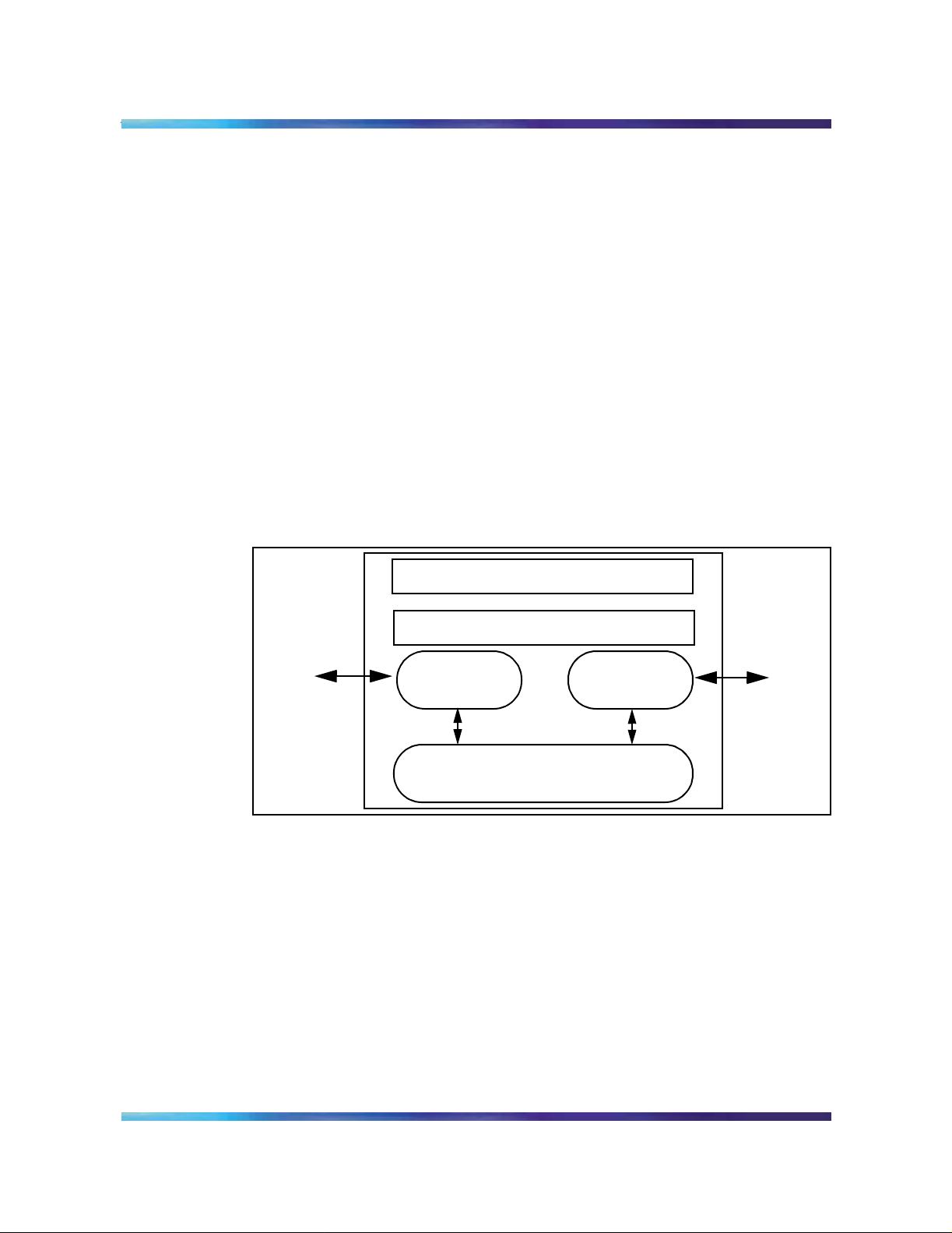
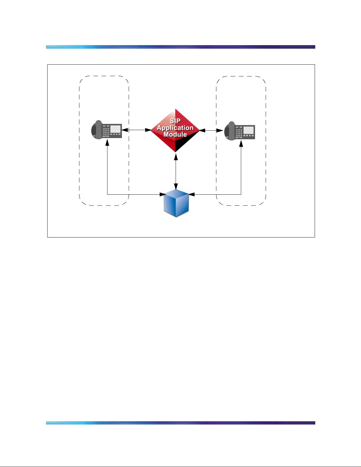
enterprise firewall. See Figure 1, “Back-to-Back User Agent
service.”
Figure 1 Back-to-Back User Agent servic e
Overview 5
Application Module remains on the signaling path
supplied by the RTP Media Portal to control media endpoints
userA
User
Agent
Client
User
Agent
Client
userB
Internal Protocol
Routing in a S IP network is based on the same hop- by-hop principle
as routing e-ma il within the Internet. Th e next hop for a S IP request
is determined by a pr oxy using th e domai n or the host p art of a SIP
URL (user@domain). The terminating proxy determines whether
the domain sent in the SIP URL is one of the domains managed by
the SIP proxy. Otherwise, the SIP request is forwarded to another
Proxy based on the location lookup performed by the
SIPApplication Module. The SIPApplication Module supports
routing using t able l ookup i n the SIP dat abase o r using th e Domain
Name Server (DNS) to find a route.
Copyright © 2003, Nortel Networks MCP SIP Application Module Basics
Page 6

6 Overview
Nortel Networks Confidential
• Redirect Server
The SIP Application Module decides whether to proxy or redirect the
call separately for each individual request. This decisio n is made
based on subscriber service logic. If the decision is to redirect the
request, a 302 Resp onse message is returned with a list of alternate
locations.
• Registration Server
The Registration Server performs registration on messages it
receives from clients. The Registration Server stores information in
the database.
• Location Server
The Location Server performs location lookup services using
domain and user information stored in the database.
The SIP Application Module integrates the above logical servers,
which are all defined in SIP Draft RFC 2543 (see note for specific
reference), in to a single server wi th the enhanced se rvices provided
by the Back-to-Back User Agent.
Note: J. Rosenberg et al, SIP: Session Initiati on Protocol,
Internet Draft draft-ietf-sip-rfc2543-bis09.txt, IETF, Feb 27, 2002.
Network configuration
The SIPApplication Module is configured with two network cards to
allow for a network configuration that has a private side and a public
side. Figure 2, “Example of network configuration,” shows the
SIPApplication Module and RTP Media Portal with public ports and
ports that are internal to the priv ate network. This network co nfiguration
provides security by placing all the components in a private network
and exposing only the public signaling and ports to the public network.
NN10029-111 Standard MCP 1.1 FP1 (02.02) April 2003 Copyright © 2003, Nortel Networks
Page 7
Nortel Networks Confidential
Figure 2 Example of ne twork configuration
SIP Application
BigMart.com
Module
BiggerMart.com
SIP Audio
Servers
Overview 7
Management
Module
PSTN Gateways
Accounting
Modules
Copyright © 2003, Nortel Networks MCP SIP Application Module Basics
Page 8
8 Overview
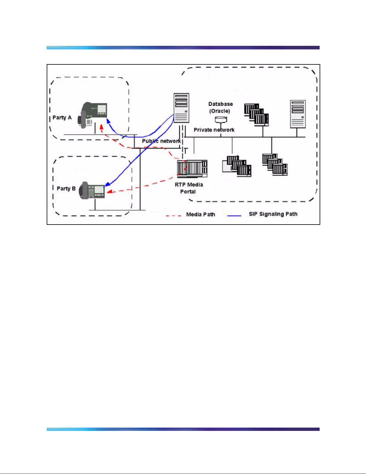
Interfaces
The SIP Application Module interfaces with numerous other
components. See Figure 3, “Network interfaces.”
Figure 3 Network interfaces
Nortel Networks Confidential
Private network
PSTN
or PBX
Access
client
Public network
Access
client
Legend
Signaling
Media stream
NN10029-111 Standard MCP 1.1 FP1 (02.02) April 2003 Copyright © 2003, Nortel Networks
Page 9
Nortel Networks Confidential
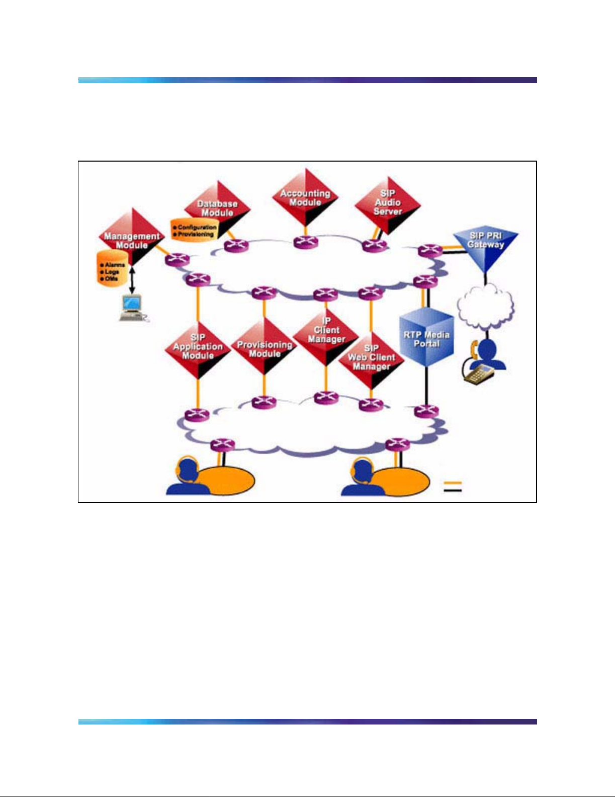
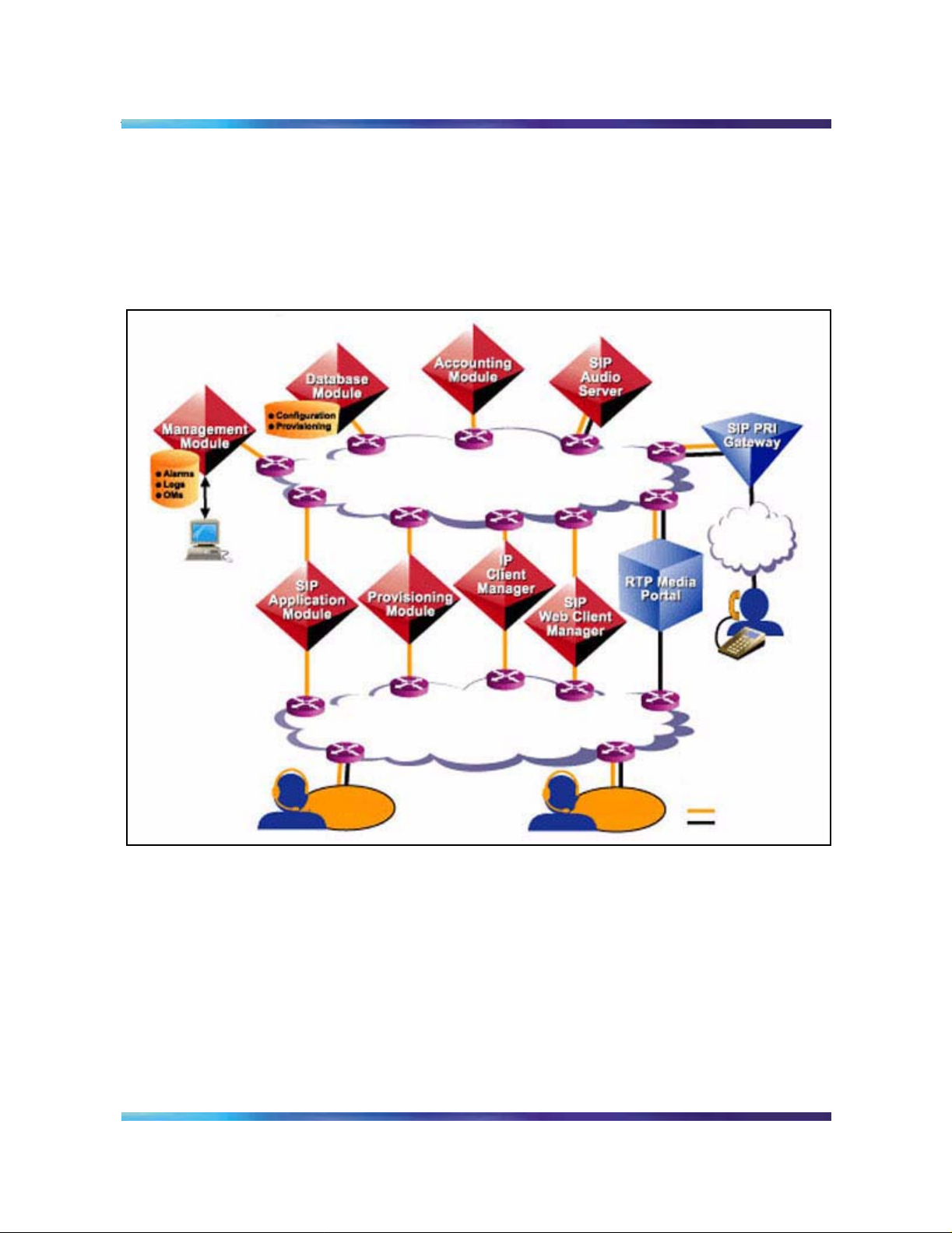
Protocols
The SIPApplication Module uses various protocols to support
SIP clients, including the Management Module, RTP Media Portal,
Database Module, and the PSTN Gateways. The protocols use an IP
backbone to connect the components. These interfaces are shown in
Figure 3, “Network interfaces.”
Figure 4 Protocols
Overview 9
OMI
PCP
SIP
SIP
SQL
SIP
Access
client
DTP
Private network
SIP
Public network
SIP
SIP
SIP
MGCP+
SIP
Access
client
SIP
PSTN
or PBX
Legend
Signaling
Media stream
Copyright © 2003, Nortel Networks MCP SIP Application Module Basics
Page 10

10 Overview
Nortel Networks Confidential
Table 1, “SIPApplication Module protocols,” gives details about these
interfaces.
Table 1 SIP Application Module protocols
Protocol Functional component
SQL Structured Query Language
Interface to the Database Module
SIP Session Initiation Protocol
Interface to the
•SIPclients
• SIP Audio Server
• IP Client Manager (IPCM)
• SIP PRI Gateway
• Web Client Manager
OMI Open Management Interface
Interface to t he SIP Management Module
MGCP+ Media Gateway Control Protocol
Interface to the RTP Media Portal
PCP Perfect Channel Protocol for logs and a larms going to
the Management Server
DTP Data Tran sport Protocol
Note: The external interfac es use an IP network to int erconnect the
components listed in this table.
NN10029-111 Standard MCP 1.1 FP1 (02.02) April 2003 Copyright © 2003, Nortel Networks
Page 11
Nortel Networks Confidential
Hardware
Refer to Table 2, “Minimum hardware requirements,” for the l ist of
required hardware.
Table 2 Minimum hardware requirements
Sun Netra t 1400(DC) /1405 (AC) Description
4-440 Mhz Ultra Sparc II CPUs
4 GB RAM
2-36 GB Ultra SCSI disk drives
1-32X Internal CDROM drive (bootable)
24 GB 4 mm internal tape drive
1 Quad Fast Ethernet PCI card
1 PCI UltraSCSI card
Overview 11
Services and features
The SIP Application Module performs the following services:
• Routing and Translations Services
— Call Transfer
— Local termination
— Foreign termination
—Redirect
— Telephony Routing
— SIP Aliases
— Multiple Route Termination/SIP Forking feature
— Call Processing Language (CPL)
• Interworking services
— Discriminator service
AC (t 1405)/DC (t 1400) power supplies
— Bearer Path Control
— Privacy Control service
Copyright © 2003, Nortel Networks MCP SIP Application Module Basics
Page 12

12 Overview
Routing and Translation services
Nortel Networks Confidential
• Service package enforcement
• Authentication services
• Converged PC service
• Network/Address Hiding
• 911 Notification support
• Instant Messaging
• Presence
• Voicemail server interope rability and MWI (message waiting
indication) notification
• Registration
• Network address book
• Overload control
• Reliability and fault tolerance
Foreign termination
If an incoming req uest specifies a do main that is not ser ved by (in other
words, is not local to) the SIP Application Module, the SIP Application
Module tries to route that request to the appropriate server for that
domain.
The first step in this process is to query the DNS SRV, if one is
configured in the system, in ord er to obtain the IP address of the server
associated with the foreign domain.
Note: A DNS SRV extends the basic functionality provided by a
traditional domain name server (DNS). It allows a protocol field to be
the query fo r a particular domain and uses that protocol field to
provide the correct IP addr ess of the server for the specifie d protocol.
For example, clients may query the server with a domain name of
nortelnetworks.com and protocol field of sip. The DNS SRV would
then respond with the IP address of the SIP server for that domain
(which may dif fer from, fo r example, t he H.323 serve r). This all ows a
domain to have different servers for different protocols.
If this query fails to find the IP address or if a DNS SRV is not
configured, the SI P Appl icatio n Mod ule atte mpt s to lo ok up t he for eig n
domain in the database to see if an IP address has been provisioned
for this foreign domain (see the SIP Provisioning Client User Guide for
NN10029-111 Standard MCP 1.1 FP1 (02.02) April 2003 Copyright © 2003, Nortel Networks
Page 13

Nortel Networks Confidential
details). If this step also fails, the SIP Application Module attempts a
general DNS A-record lookup to route the request.
Note: The DNS A-recor d is the traditiona l response given by a DNS.
It translates a domain name into an IP address.
If any of these steps succeed, the SIP Application Module routes the
request. If all these methods fa il, the SIP Application Module reject s the
request.
Call Transfer service
The SIP Application Module handles the transfer on behalf of clients
that do not support the call transfer service.
The SIP Applicatio n Module supports unattended Call T ransfer throug h
the Refer mechanism. Unattended Transfer (or Blind Transfer) refers to
cases where the transferor redirect s the transferee to the tr ansfer target
without first con fer ri ng wi th th e tr a nsfe r target. The transfer or receives
a Notify message, however, indicating whether the transfer was
successful. If it was, the transferor releases the original call. If it was
not, the transferor is reconnected to the transferee.
Overview 13
Local termination
The SIPApplicat ion Module fir st determines w hether the incom ing SIP
request terminates to a client in a domain managed by the
SIPApplication Module. The SIP Application Mod ule performs local
routing lookup through the Location Server, which is part of its internal
software.
Telephony routing
When the SIP Application Module receives an incoming call, it looks up
the callee in the database. If the callee is not in the database but the
domain is served and the user portion of t he URL is a T elep hony routing
number, the Telephony routing number is sent through the Telephony
routing software within the Location Server.
The Te leph ony r outin g s oftware must perfor m digi t tra nslat ion to fin d a
gateway to terminate a call to. These t ables are located in the Database
Module. You can provision them through the Provisioning Client. For
more information, refer to the SIP Provisioning Client User Guide and
the MCP Database Module Basics document.
The Telephony routing service allows the SIP Application Module to
• provide unique dial plans for each subdomain
• provide routes to gateways or to other domains
Copyright © 2003, Nortel Networks MCP SIP Application Module Basics
Page 14
14 Overview
Nortel Networks Confidential
These routes include routes for private digit dial plans, routes to
gateways, and telephony-style routing between SIP domains.
Multiple lists can reuse the same routes in a route list.
• assign class of service (COS)
COS is basically used to block particular types of calls, such as
international dialing or long-distance dialing. For example,
telephones in an office lobby can be restricted to local and
emergency calls only in a domain.
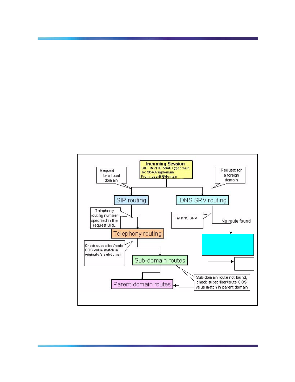
Figure 5, “Relationship between Telephony routin g st ag es,” shows th e
relationship betwee n the tele phony ro uting sta ges provi ded by the S IP
Application M odule. If the C OS val ue of the subscri ber and subdom ain
route do not match, then the SIP Ap plication Module checks the pa rent
for routes with the same or higher COS value.
Figure 5 Relationship between Telephony routing stages
No subscriber
Foreign domain routing
Do database lookup
Failed
*If the DNS A record fails, a 404 Error response is sent back to the originator.
DNS A
record*
Route lists The T elephony routing service is an enhancement to the Location Server on the SIP Application Module. This enhanced Location Server function has the ability to translate PSTN numbers into
NN10029-111 Standard MCP 1.1 FP1 (02.02) April 2003 Copyright © 2003, Nortel Networks
Page 15

Nortel Networks Confidential
URL addresses specifying an appropriate gateway . It supports the use
of digit translation and digit manipulation.
A route list is assigned a single COS. The route list provides the
following additional options that can restrict incoming sessions from
using the domain’s telephony resources:
• allow/block all incoming sessions from other domains
• allow/block all incoming sessions from other subdomains
• redirect session to the orig inator’s domain. This option can be used
to redirect an incom ing reque st from ano ther domai n that is r outing
to a restricted route list.
Route lists consist of
• private telepho ny routes, which a re used for privat e telephony-styl e
digit dial plans
• gateway routes, which provide access to the gateways
• SIP telephon y routes, which point to oth er SIP Application Mo dules,
and SIP domains and subdomains for interdomain routing using
telephony-style dial plans
Overview 15
SIP Aliases
Alias URLs can be used to refer to a SIP client in the network. For
example, a user “sip: u serA@domainX. com” can also be ref erred to by
an alias of “sip:41037@domainX.com”.
If an incoming request specifies the “sip:41037@domainX.com” alias in
a Request-URI, the alias takes precede nce over gateway ro uting
translations, and r ou ting information pert aini ng to use rA i s r etri eve d. I f
an alias of “sip:410 37@domain X.com” is not confi gured, then g ateway
routing translations are performed to find out if a terminating gateway
exists.
Multiple Route Termination
If a single SIP user is registered at more than one device (PSTN or
SIP), forking is used to terminate a session simultaneously or
sequentially to multiple devices.
The SIP Application Module interfaces with the SIP database to
determine the use r routing preference, the r outes available, and ro uting
options for a particular user. The user defines these options through the
SIP Personal Agent. For additional information on the SIP Personal
Agent, refer to the on-product help and SIP Personal Agent Getting
Started Guide.
Copyright © 2003, Nortel Networks MCP SIP Application Module Basics
Page 16

16 Overview
Call Processing Language
Nortel Networks Confidential
With simultaneous ringi n g, the call terminates to multiple routes at the
same time. The first terminating route to answer is accepted and the
rest of the routes are released.
With sequent ial ringi ng, the call tries to terminate to on ly one of several
routes at a time. Route advancement occurs whenever an error
response is received, a provisionable No Answer timer expires, or a
redirect response is received.
The SIPApplication Module supports the use of the Call Processing
Language (CPL), based on the IETF CPL draft, draft-ietf-iptel-cpl.txt.
SIP clients can ch ange the behavior of a session using a CPL script
that contains general directives for routing a request.
For example, subscribers can include CPL scripts in the body of
registration requests that contain instructions for location lookups and
call screening, a pr ocess that is actually done th rough the Call Manager
in the Personal Age nt. Third-p arty client s can also up load script s using
the Registration mechanism. The Registration function of the
SIPApplication Module stores the request. When the SIPApplication
Module is queried for routing information for a subscriber who has valid
data stored in the database, the software returns the script along with
the routing information. The SIPApplication Module applies the CPL
script to the returned routes and can eliminate or alter the routes based
on the CPL script.
CPL scripts do not support the following:
• Remove location
• Mail option
• Log option
Interworking services
Discriminator service
The SIPApplication Module screens requests bound for devices that
are not fully SIP compli ant, for example, the Communication Server for
Enterprise (CS E) 2000. These comp onents canno t process all types o f
signaling and certain media change requests. Therefore, the
SIPApplication Module either performs the requested operation or
rejects the request and responds with an error response.
The Discriminator service works with various gateways and SIP clients
using provisioning facilities implemented by the SIP Application
Module. As gateways or SIP clients with limited SIP capability are
added to the network, this service can be configured to support these
NN10029-111 Standard MCP 1.1 FP1 (02.02) April 2003 Copyright © 2003, Nortel Networks
Page 17

Nortel Networks Confidential
devices. Information for each component is stored in .xml format to
provide flexibility when describing the capabilities o f the component.
Bearer Path Control
The SIPApplication Module uses the RTP Media Portal to control
media streams originating from and terminating to non-compliant SIP
devices if they d o not support media negotiations. The ex ception to this
occurs when the o rigin at ing a nd ter minat in g p art ie s are both th e sam e
device type. If both gateways are CSE 2000s, for example, the SIP
Application Module does not use the RTP Media Portal.
Privacy Control service
The SIP Application Module supports Privacy Control based on
draft-ietf-sip-privacy. This draft defines a mechanism that allows clients
to supply a network server with their private user information while at
the same time instructing the server no t to pass that information outside
the boundaries of the truste d network. The information is passed in a
Remote-Party-ID header with the privacy indica tor set to “full.” The SIP
Application Module removes this header any time it forwards the
message out over a public network interface.
Overview 17
Service package enforcement
A service package is made up of a user’s enabled network services,
such as audio conferencing, and subscriber profile. The service
provider defines the available service packages for the domain. The
domain provisioner can then assign a specific service package to a
subscriber.
Authentication services
The SIP Application Module performs user authenticat i on when the
server receives an incoming SIP request. The SIP Applicatio n Mo dule
supports the challenge-based Digest method for SIP Client-to-Proxy
authentication. In Digest authentication, the SIP Application Module
challenges a client when a SIP request is received. The SIP Client
re-sends a SIP requ est with a valid password an d user name att ached.
The request types to be authenticated are configurable.
Note: Only US ASCII is supported for user names.
The software performs authentication using the password of the
subscriber originating the call. Only subscribers from a local domain
actually have a password stored in the database to authenticate
against. If a subscriber from a foreign domain (refer to t he no te below
for definitions of these types of domains) places a call and
authentication is required for a known foreign domain, the
Copyright © 2003, Nortel Networks MCP SIP Application Module Basics
Page 18

18 Overview
Converged PC service
Nortel Networks Confidential
authentication fails since the database does not have the subscriber's
information. As a result, the call is blocked.
Administrators can configure whether they want a call from an unknown
foreign domain authenticated or not. System administrators can also
specify foreign proxie s in the Nodal Auth fiel d of the Authenticati on t ab.
In this way, no requests originating from those proxies are failed
because of authentication.
Note: The following definitions apply:
• Local Domain: Local domains are provisioned for and serviced by
a particular SIP Application Module. Su bscribers for a particular
system belong to local domains. Local domains are provisioned
through the Provisioning Client.
• Foreign Domai n: A foreign domain is a domain that is eithe r
provisioned as foreign for this SIP Application Module or not
provisioned at all for this specific system. It b asically represents a
domain that is not served.
The Converged PC service allows end users to use their PCs for the
multimedia portion of their communications while using their existing
telephony system for voice. The service uses the simring feature on an
existing telephony system to send mirrore d calls to the SIP Application
Module through the SIP PRI Gateway . This allows the SIP Application
Module to presen t a ca ll wi ndow o n the end user 's PC w hen t he use r's
desktop phone rings.
If both parties in a call are Converged users, they will each get a call
window from which they can initiate multimedia sessions such as
Instant Messaging and collaborative applications between each other.
Some benefits of providing multimedia services using the Converged
service are:
• End users can keep using their existing telephone and its
capabilities.
• There is no need to replace an existi ng telephony switch to add
multimedia capabilities.
NN10029-111 Standard MCP 1.1 FP1 (02.02) April 2003 Copyright © 2003, Nortel Networks
Page 19

Nortel Networks Confidential
The Converged service adds the following cap abilities to the end user's
telephony service:
• the ability to manually redirect incoming calls to another party from
the PC
• the ability to set up automated enhanced routing and screening of
incoming calls based on time of day or based on the calling party's
identity
• a call log of all incoming calls
• the ability to send instant messages to the party on the other end of
a call
• the ability to start collaborative applications such as shared
whiteboard, file transfer, and clipboard transfer with the party on the
other end of the call
• the ability to receive a picture ID of the party on the other end of the
call
Network/Address Hiding service
The SIP Application Module uses SIP and the Session Description
Protocol (SDP) to coordinate the establishment of multimedia sessions
for signaling and media, respectively. These protocols embed IP
information in their messaging. While Networ k Address Translation
(NAT) devices change port and address informati on in the IP packet
header , most are not currently SIP or SDP aware. IP addresses in these
messages are theref ore sent out unchange d through the NA T. If the SIP
Application Mo du le were to for w ar d the se messa ge s on uncha nged,
sensitive IP inform ation w ould be gi ven to untr usted clien ts. In or der to
remedy this, the SIP Application Module sanitizes the messages before
forwarding them.
Overview 19
For IP information in the SIP headers, the SIP Application Module
either removes the header (for example, Via headers) or replaces the
IP address with the address of the SIP Application Server (for example,
Contact head er). A media portal is necessary in order to re place the IP
information in the SDP headers. The SIP Application Module queries
the Media Port al (u si ng M GC P+) for a new IP and port combi n ati o n to
replace the IP and port put th ere by th e client . This ef fe ctively an chors
the media stream at the Media Portal.
Clients therefore see the SIP Application Module as their signaling
endpoint and th e Media Port al as their R TP media en dpoint. They have
no knowledge, and therefore no IP information, about the other client
they are in a session with.
Copyright © 2003, Nortel Networks MCP SIP Application Module Basics
Page 20

20 Overview
Nortel Networks Confidential
The RTP Media Portal handles Network Hiding for the media stream.
For information on the R TP Media P ortal, re fer to the MCP RTP Media
Portal Basics document.
Note: The SIPApplication Module cannot map SDP information
without an RTP Media Portal. It only performs address mapping for
SIP header fields. Therefor e, SDP p asses thr ough unto uched. If the
server must map SDP address information, then you need an RTP
Media Portal.
The SIPApplication Module is configured to use an RTP Media Portal
to originate and terminate media streams (RTP/RTCP). The
SIPApplicati on Mod ul e uses exte nd ed Me di a Gatew ay Co ntr o l
Protocol (MGCP+) to allocate and release resources on the RTP Media
Portal for each session as needed.
Enterprise Clients
The SIPApplication software uses the RTP Media Portal to hide
sensitive IP address information about SIP clients behind a firewall in
an Enterprise netw ork. The exception to th is occurs when the orig inator
and terminator of the request are both part of the same network. This
status is de ter min ed b y ch ecki ng th e do mains in the From head er a nd
Request-URI of the SIP Invites. If both SIP clients belong to the same
Enterprise netw or k, th e S IP Ap pl i cation Module does not u se th e RTP
Media Portal. Adm inistrators can overri de this behavior by provision ing
the AlwaysUseMediaPortal domain parameter in the Provisioning
Client (for more information about this parameter, see the SIP
Provisioning Client User Guide). See Figure 6, “RTP Media Portal
interworking with Enterprise or foreign clients.”
NN10029-111 Standard MCP 1.1 FP1 (02.02) April 2003 Copyright © 2003, Nortel Networks
Page 21
Nortel Networks Confidential
Overview 21
Figure 6 RTP Media Portal interworking with Enterprise or foreign clients
Public
Domain
SIP
Client
SIP
RTP/RTCP
911 Notification support
The SIP Application Module supports Instant Message notifications to
a specified On-Sit e Notification (OSN) location whenever a user makes
a call to an emergency number such as 911. The software provides this
service using the same mechanis m that allows us ers to push web
pages and/or email links back to the originator of a call. In order to do
this, administrators set up (at the Personal Agent) an emergency
subscriber for each OSN location and a private telephony route to map
the emergency number to this subs criber. Since telephony routes are
only unique w ithin a sub doma in, you canno t have mo re t han one OSN
location for each subdomain.
Enterprise
Domain
SIP
Client
SIP
MGCP+
RTP/RTCP
RTP/RTCP
Media Portal
For each new emergency subscriber that the administrator creates,
there must be both
• an emergency numbe r to route to the Public Safety An swering Point
(PSAP)
• a SIP subscriber assigned t o the OSN loca tion that is to rece ive the
notification.
Each OSN location must have a specific subscriber assig ned, such
as sip:guarddeskA@nortelnetworks.com.
Copyright © 2003, Nortel Networks MCP SIP Application Module Basics
Page 22

22 Overview
Instant Messaging
Presence
Nortel Networks Confidential
For more information a nd the procedure for setting up In stant Message
notifications to emergency numbers, see the SIP Provisioning Client
User Guide.
Instant Messages are routed in parallel only to a subscriber' s
dynamically registe r ed r ou tes ( see “Reg i str ati on —static and dynamic”
on page 24). This is in contrast to session initiation requests, whi ch are
subject to CPL routing logic. Upon receipt of an instant message, a
client may respond back to the address supplied in the Contact header.
This ensures that the response is sent back to the same client device
that originally sent the message .
When a user initially reg isters, by default th eir presence st atus is set to
“on-line” in the SIP re gistration message . Users subscribe to watch the
status of other use rs, and to coordinate the status of their own devices.
This information is maintained in an in-memory table on the SIP
Application Mo dule (Presen ce software). The informatio n that is stor ed
in this table includes:
• the user to be watched
• the party reque sting the subscription
• the correlation informatio n identifying that particular subscription
request
• contact information regarding where to send the notifications that
are generate d as a result of the subscription being active
When a user chan ges their presence (for example, to Busy), a
registration message is automatically sent to the SIP Application
Module.
The SIP Application Module then checks its in-memory table to see
what their previous prese nce state was. If the update causes a m aterial
change in their presence state, the SIP Application Module looks up
which users need to be notified of the change (also in memory). This
is done by sending a Notify message to each user at every contact
contained in the table. For more information, refer to the MCP SIP
Presence Basics document.
Voicemail server interoperability and MWI
In order to accomplish voicemail server interoperability and MWI
(message waiting indication) notification, the SIP Application Module
NN10029-111 Standard MCP 1.1 FP1 (02.02) April 2003 Copyright © 2003, Nortel Networks
Page 23

Nortel Networks Confidential
transmits the following information over a data link to a voicemail
server:
• the called number (terminating party's telephone number)
• the calling numb er
• the type of call forwarding (for example, due to a busy line, an
unanswered call)
This feature also provides an interface to pure IP solutions that use a
SIP-enabled voicemail server. In this case, SIP messages provide the
context data for each call needed by the voicemail server to record a
voicemail message. Thus, a SIP-enabled voicemail server accepts
Invites for calls routed to voicemail and sen ds Notify messages for MWI
information. The softwar e uses Real -T im e Transport Protoc ol (R TP) to
carry the voice media.
There are two co nfigurations throu gh which the SIP Ap plication Module
supports voicemai l:
• A pure IP, third-party, SIP-enabled voicemail server that uses RTP
to establish the voice path from the subscriber to the voicemail
server while SIP provides the setup and MWI information.
Overview 23
• A legacy voicemail server that uses a SIP/PSTN gateway to
establish the voice path from the subscriber to the PSTN-based
voicemail server. The Simplified Message Desk Interface (SMDI)
protocol provides the setup information. The platform uses any
voicemail server that suppor ts the SMDI protocol. There are two
supported physical connections: a line-based gateway and a
PRI/T1-based gateway.
Using either of the above configurations, there are three primary
scenarios that this feature co nsiders:
• MESSAGE DEPOSIT: An incoming call for a subscriber gets rout ed
to voicemail because the called subscriber is unavailable, busy, or
has all calls forwarded to voi cem ai l.
• MESSAGE NOTIFICATION: The voicemail server sends an MWI
status update to the SIP Application Module for a particular
subscriber. The SIP Application Module then sends a message to
the client(s) to update its MWI display.
Note: Clients do not store the MWI state. Only the Presence
Module stores the state. When a client registers with the proxy
Copyright © 2003, Nortel Networks MCP SIP Application Module Basics
Page 24

24 Overview
Nortel Networks Confidential
and has messages waiting, the system sends a Notify to the
client.
• MESSAGE RETRIEVAL: A subscriber calls the voicemail server for
message retrieval. The subscriber is then connected to the
voicemail server and accesses the mailbox to retrieve messages.
When you provision the voicemail server, specify which SIP Application
Module is the host (see the Configuration chapter in this docume nt for
details). Only the SIP Application Module that is hosting a particular
voicemail server attempts to establish an SMDI connection with that
voicemail server.
Note: SMDI is used in certain voicemail configurations to allow the
voicemail server to send Message Waiting Indication information to
the SIP Application Module. Also when connected to a lines-based
voicemail server, the SIP Application Module sends an SMDI
message to the voicemail server when a call is being routed to
voicemail for messag e deposit. The SMDI information includes which
mailbox the message should be deposited in. Also, the voicemail
server periodically sends an SMDI heartbeat message to the SIP
Application Mo dule. The SIP Application Mod ule must respond to this
message to let the voicemail se rver know that the SMDI link is still up.
Registration—static and dynamic
Registration can take two forms:
•Static
Users or administrators can perform st atic registra tions. With st atic
registration, the user can obtain a presence when not logged into
the network. The user can obt ain a presen ce and an accoun t in one
of the following ways:
— Using the SIP Provisioning Client, the administrator can add a
user account and assign a static route.
— When users have accounts, they can add contact information,
such as PSTN numbers or cell phone numbers, to their routing
information.
•Dynamic
Once a user logs in, re-registration is automatic with the SIP
Multimedia PC Client, the SIP Multimedia Web Client, and the
IPCM. The IPCM takes car e of this re-reg istr ation aut omati cal ly for
the i2004. Dynamic registration is automated and behind the
scenes.
NN10029-111 Standard MCP 1.1 FP1 (02.02) April 2003 Copyright © 2003, Nortel Networks
Page 25

Nortel Networks Confidential
Network address book
Client Address Book information is stored in the network so that it can
be accessed from all clients. The information is downloaded in bulk
whenever a client comes on line (either through a Simple Object
Access Protocol [SOAP] int erface or direct database access depend ing
on the client).
In order to receive updates to the Address Book after the initial
download, the c lient subscribe s to the Address Book event package
and updates it as needed. Whenever an update is made through the
Personal Agent or one of the clients, a Notify message is sent to the
client indicating which entries have changed. The client can then
incrementall y update their view of the info rmation (aga in either thro ugh
a SOAP interface or direct database access depending on the client).
A List of Buddie s is incorporate d as part of the Address Book. Each
subscriber must create th eir own personal Address Book an d designate
their own Buddies. For each of these specified entries, the client
automatically subscribes to their pre sence eve nt packa ge. Thi s allows
them to monitor and update the network presence of each Buddy (for
example, online or offline).
Overview 25
Overload control
Overload Control monitors the Incoming Protocol Message Queue
Length. If this queue l ength crosses a configurable threshold value, the
system performs Session Blocking, allowing no new incoming request s
to process. The system does, however, continue to process requests
for an established session. For rejected requests, the system sends a
“503 Service Unavailable” response with a Retry-After header, which
specifies the amount of time a client should wait before retrying the
request.
Note that multiple thresholds may be crossed simultaneously. If this
occurs, the appropriat e actions are invoked and are not cleared until al l
aspects of the system have crossed below the assigned threshold
value.
Copyright © 2003, Nortel Networks MCP SIP Application Module Basics
Page 26

26 Overview
Reliability and fault tolerance
Nortel Networks Confidential
The SIP Application Module provides reliability and fault tolerance
through multiple SIP Application Mo dules deployed in an N+M
active-standby configuration.
Note: The supported active/standby configurations include:
• a 1+1 configuration (one active plus one standby server), which
is the most basic reliable configuration
• an N+M configuration of up to four servers (the sum of N plus M
should not exceed 4)
— a 2+1 (2 active and one standby)
— 2+2 configuration
— 3+1 configuration
To accomplish this, all the servers in a reliability group are configured
with the same set of NSDs. This gives the standby server the
information it needs in case an active server fails. Each server in the
group transmits messages indicating its current state. Other servers
respond with their curren t states, including th e NSD activated on the m.
An initializing server configures itself with one of any inactive NSDs. If
all NSDs are active, the initializing server becomes the standby. This
prevents confl i cts where more than on e server is activating
simultaneously.
Before activating, the server determines whether it is isolated from
critical network resources defined through provisioning. If any of the
resources cannot be reached, the server cannot activa te and raises an
alarm. The alarm clears when the resources become available.
When there are two or more active servers, the g roup is called a cluster .
You can configure b oth the N+M strate gy and the cluster at the
Transport Management tab in step 22 in the Configuration chapter.
When one of the active SIP Application Modules fails, the passive
Module takes over the IP address. The passive Module has now
become active and assumes the responsibilities of the failed Module.
When this occurs, any sessions already in the active state remain up.
This means that ca lls that ha ve already bee n establ ished contin ue and
the parties maintain voice path. Any future requests during that session,
however , fai l (for examp le, Hold, Retr ieve, and W eb Pu shes) since th e
session information is no longer available. Any sessions that were not
in the active state bef ore the failove r ar e lost. The ori ginating clien ts o f
NN10029-111 Standard MCP 1.1 FP1 (02.02) April 2003 Copyright © 2003, Nortel Networks
Page 27

Nortel Networks Confidential
these sessions either receive no indication or continue to hear an
alerting tone for an indefinite period of time.
Manual failover
There are two recommended procedures for manually initiating the
fail-over of an active instance to a Standby node: the initiation of
discrete LOCK and UNLOCK actions, or the initiation of a restart.
Lock/Unlock If you want to force a fail-over in order to perform maintenance on the "failed" se rver, then request a LOCK from th e Management Console. The LOCK forc es the component into a disabled operational state, where it remains until you request an UNLOCK from the Management Console. You can perform any maintenance on the "failed" server while it is LOCKed. Once maintenance is complete, the server can be UNLOCKed from the Management Console, which causes an automatic restart and brings the server back into service.
Overview 27
Copyright © 2003, Nortel Networks MCP SIP Application Module Basics
Page 28

28 Overview
Nortel Networks Confidential
Restart If you want to simply force an immediate manual fail-over, then you can request a Restart from the Management Console.
WARNING
The N+M reliability strategy provides a highly
available service environment. The fail-over
mechanisms enable an instance of the S IP
Application Module to survive failure condition(s) by
migrating to a standby server where it can resume
the processing of new sessions.
In such a highly available service environment the
failed instance loses all knowledge of sessions
started before the fail-over event. Therefore, the
stability of these pre-existing sessions cannot b e
guaranteed. For examp l e:
Sessions involving SIP clients will survive until the
clients encounter a "no response" or "unknown call"
response to a request on their active se ssion. At that
point the clients will release the session and its
associated media resources.
For more information, see the Configuration chapter in this document.
OAM&P strategy
The Management Module manages the OAM&P functions for the SIP
Application Module. For additional information, refer to the MCP
Management Modu le Basics and the MCP System Management
Console Basics documents.
Sessions involving the MCP SIP PRI Gateway will
survive until there is no response to the SIP PRI
Gateway-generated SIP "ping" to the SIP Application
Module(s) handling the active sessions on the
gateway. If there is no response to the SIP "ping"
then the gateway will tear down the associated call
and recovers its resources.
Also, sessions involving the MCP RTP Media Portal
will not survive a manual fail-over because
intentionally LOCKing the SIP Application Module
initiates the automatic recovery of all resources
(including RTP Media Portal resources) associated
with in-progress sessions.
NN10029-111 Standard MCP 1.1 FP1 (02.02) April 2003 Copyright © 2003, Nortel Networks
Page 29

Nortel Networks Confidential
Upgrades
For information on upgrading from one full relea se to another, refer to
the Installation and Commissioning document you receive wi th the
upgrade.
Updating the SIP Application Module software
Administrators can update the software version of the SIP Application
Module using the System Management Console. The update can be
either an up- or down-version of the software.
Updating the software affects the operation of the component’s hosted
services during the procedure. This process automatically fills the
service property fields of the updated component with the configured
values from the previous version.
The update introduces new functionality across many components
without affecting network stability. If a server update fails, you have a
choice to roll back or not. For more information on the update
procedure, refer to the MCP System Manageme nt Co nso le Basi cs
document.
29
at the System Management Console
1 A load can be either up-versioned or down-versioned. In either
case, updating a load from one version to another results in
stopping and deleting the previously added version, adding the
new version and auto-launching the new version. Therefore,
there is no need to manually LOCK and UNLOCK the service.
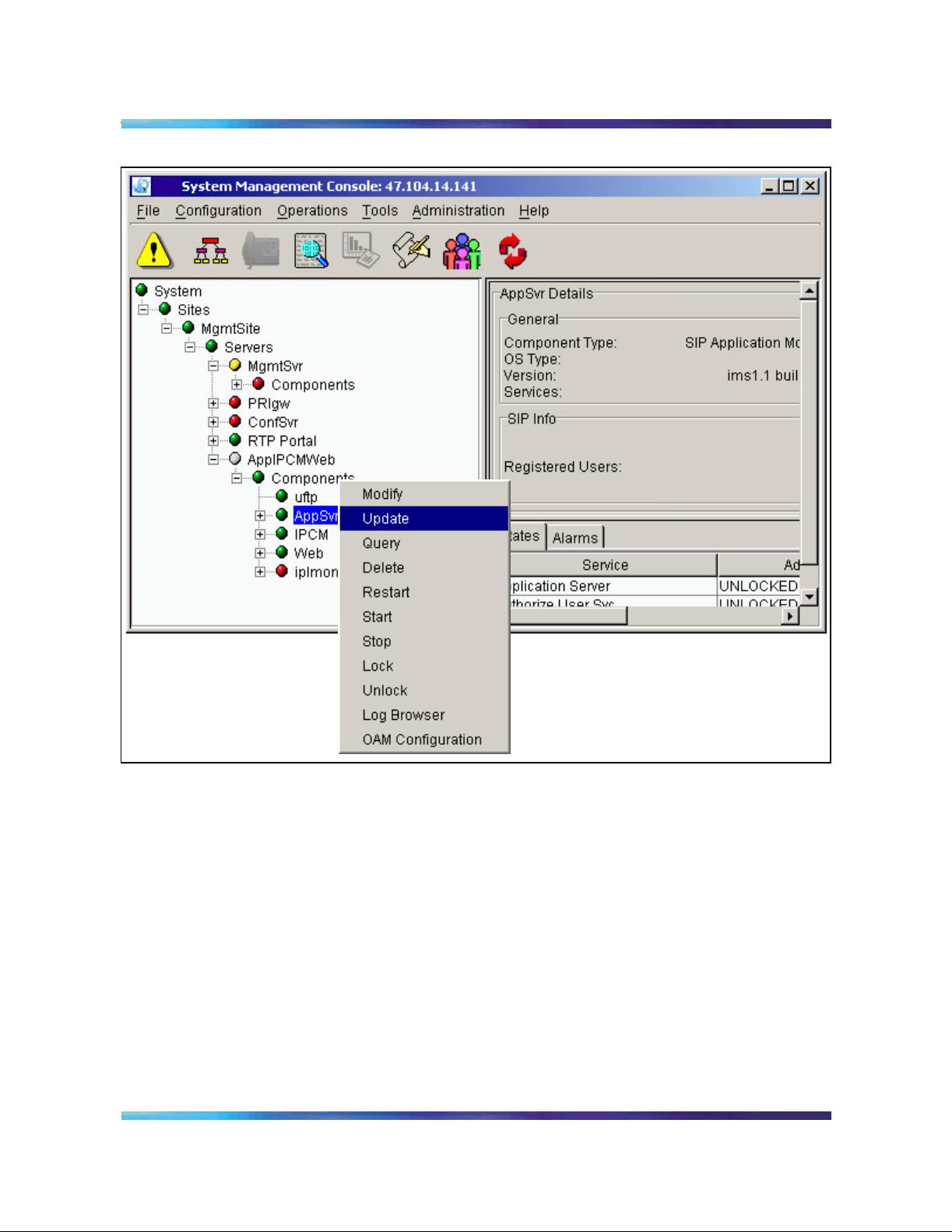
The steps involved in an update are described below.
From the System Management Console, under the
Components folder , sele ct the name configured at deployment,
AppSvr in the example shown in Figure 1.
Copyright © 2003, Nortel Networks MCP SIP Application Module Basics
Page 30
30 Upgrades
Nortel Networks Confidential
Figure 1 Updating the Application Module from the menu tree
You can also launch the update from the pull-down
Configuration menu, as shown.
NN10029-111 Standard MCP 1.1 FP1 (02.02) April 2003 Copyright © 2003, Nortel Networks
Page 31

Nortel Networks Confidential
Upgrades 31
Figure 2 Updating the SIP Application Module from the pull-down menu
2 Select the Update command. The foll owing window appea rs.
Figure 3 The update window, retrieving the load list
Copyright © 2003, Nortel Networks MCP SIP Application Module Basics
Page 32

32 Upgrades
Nortel Networks Confidential
3 Because only versions not currently deployed appear in the
loadlist following the Add->Component step in the update
procedure, multiple versions may not appear for the update
operation. You can only do an update from one version to
another. Therefore, the window only shows loads that have the
same name as the lo ad being updated (see Figur e 4, “Load list
for updating”).
Figure 4 Load list for updating
4 Select the version you want to update. Click on th e Apply
button.
5 The configuration window appears, showi ng the ta bs. Modify all
the configuration values you need to modify. Then click on the
Apply button. The window that appears shows the progress of
the update (see Figure 5, “Progress of update”). Each
configured manage d object (MO) app ears as being successf ully
added onto the managed element (ME).
NN10029-111 Standard MCP 1.1 FP1 (02.02) April 2003 Copyright © 2003, Nortel Networks
Page 33

Nortel Networks Confidential
Figure 5 Progress of update
6 Once the update has complete d, th e fo llo w ing w ind ow ap pe ar s.
Upgrades 33
Figure 6 Successful update dialog box
OAM&P strategy
The Management Module manages the OAM&P functions for the SIP
Application Module. For additional information, refer to the MCP
Management Module Basics and the MCP System Management
Console Basics documents.
Copyright © 2003, Nortel Networks MCP SIP Application Module Basics
Page 34

34 Upgrades
Nortel Networks Confidential
NN10029-111 Standard MCP 1.1 FP1 (02.02) April 2003 Copyright © 2003, Nortel Networks
Page 35

Nortel Networks Confidential
Fault management
The Management Module manages the faults for the SIP Application
Module. For additi onal information on the Mana gement Module, refer to
the MCP Manageme nt Mo du le Basics and the MCP System
Management Console Basics documents.
How this chapter is organized
This chapter is organized as follow s:
• Alarm clearing procedures
• Recovery procedures
Alarm clearing procedures
Procedure 1 Clearing the SLE701 (SLEE Health Monitor) alarm
at the alarm browser
1 The SIP Application Module raises this warning alarm under one
of two conditions:
35
• The number of ap plication contexts (AC) available for use
are inadequate for the level of traffic (in which case the
administrator needs to back off the traf fic or call the next level
of support).
The SIP Application Module raises this alarm when AC pool
use reaches or exceeds 80%. The alarm clears when use
drops below 80%.
• There is an error condition that is caus ing ACs to be
consumed at a higher than normal rate. This could be due to
a myriad of things; for example, the system might be
consuming RetrieveSubscriber ACs at a high rate because
the database is overloaded.
Severity is MAJOR. The SLEE is a service processing
environment. An AC is a unit of work within that processing
Copyright © 2003, Nortel Networks MCP SIP Application Module Basics
Page 36

36 Fault management
Procedure 2 Clearing the SMDI101 alarm
at the alarm browser
1 This alarm is raised when the Simplified Message Desk
Nortel Networks Confidential
framework. For example, when you register your phone, a
number of AC instance s are invoked to process the regi stration.
Interface (SMDI) telnet session between the SIP Application
Module and a terminal server is lost. The SIP Application Module
uses the SMDI pr otocol to communicate information between
itself and a voicemail server. If the connection goes down,
• Message W aiting Indica tion notification to subscribers stops.
• Calls routed to the voicemail server are not sent to the
appropriate mailbox.
However, depending upon the voicemail server’s capabilities,
the calls may be answered by a default mailbox and the
originator can enter the desired mailbox number in which to
leave a message. In the same way , users may be able to retrieve
their voicemails (for example, they get routed to the default
mailbox and are prompted to enter their mailbox). Again, this
functionality depends upon the voicemail server being used.
The SIP Application Module repeatedly tries to re-establish the
telnet session to the terminal server. If the alarm does not go
away in a few minutes, then the terminal server needs to be
checked and possibly re-booted. Al so, admi nis tra tor s shou ld
check the voicemail server to make sure it is running correctly. If
problems persist, contact your next level of support.
NN10029-111 Standard MCP 1.1 FP1 (02.02) April 2003 Copyright © 2003, Nortel Networks
Page 37

Nortel Networks Confidential
Configuration
How this chapter is organized
This chapter describes the pro cedures for configur ation required a t the
service provider premises. This chapter is organized as follows:
• “Overview” on page 38
• “Adding a component” on page 40
• “Configuring the SIP Application Mo dule tabs” on page 44
— Applicatio n Ser v er
— Long Call Service
— Presence
— Presence Location Service
— Authentication
—Media Portal
— Locate User Svc
37
— Database Base
— Data Synchronization
— Prov Sync Service
— Overload Controls
— Forward Locati on Service
— Local Accounting Manager
— In Memory Database
— Location Service
— Registration
— Server Properties
— Server Subscription
— SIP TCF Base
Copyright © 2003, Nortel Networks MCP SIP Application Module Basics
Page 38

38 Configuration
Overview
Nortel Networks Confidential
— Svc Pkg Enforcement Service
— SipFwdAdapter
— Transport Management
• “Additional SIP TCF Base tab configuration information” on page 90
• “OAM&P strategy” on page 92
CAUTION
Before making any changes to the base
configuratio n, consult your next level of support .
.
Nortel Networks performs the initial installation and commissioning.
Once the install ation and commissioning are comp leted, you can begin
to make your system fully operational. The following list identifies some
general tasks:
• provision and complete translations to enable voice and trunk
services
• configure any additional services, applications, and features that
Nortel Networks i s not contracted to perform
• complete the installation of clients or add client software for all
management interfaces
The SIP Application Module is configured using the System
Management Console. For more information, refer to the MCP
Management Modu le Basics and the MCP System Management
Console Basics documents. This chap ter describes the configurable
parameters affecting operation of the SIP Application Module and the
procedures for config uration requi red at the service provi der premises.
Deployment from the System Management Console results in the
installation of all SIP Application Module-specific software and
configuration data on the host machine, and starts the software
processes. Undeployment stops the software processes and remove s
all related software and configuration data. When the deployment is
complete, the SIP Application Module should be unlocked, enabled,
and available to provide servic e.
Before a SIP Application Mod ule can be de pl oye d, the server must
have been configured at the System Management Console. This server
NN10029-111 Standard MCP 1.1 FP1 (02.02) April 2003 Copyright © 2003, Nortel Networks
Page 39

Nortel Networks Confidential
represents the physical hardware on which the SIP Application Module
resides. Once the servers are configured, the SIP Applicatio n Module
can then be deployed.
The SIP Application Module depends on various components that
require configuration during the deployment process. In general, most
of the SIP Application Module’s configuration items can be left with their
default values; however, administrators should familiari ze themselves
with the available options.
Administrators can also find h elp te xt with de scriptions an d accept able
ranges by holding the cursor over the field name as shown in Figure 1,
“Displaying help text.”
Note: In all tabs, the fields with asterisks (*) require an entry. The
grayed-out fields are for information only and cannot be changed.
Change all occurrences of the IP address “0.0.0.0” to the proper IP
address for your situation.
Figure 1 Displaying help text
Configuration 39
Copyright © 2003, Nortel Networks MCP SIP Application Module Basics
Page 40

40 Configuration
Adding a component
This procedure assumes that the serve r on whi ch the SIP Application
Module will be depl oyed has already been configured. For example,
Figure 3, “Adding a component,” shows the SIP Application Module
being deployed onto the previously configured server. For the
procedure for adding a server, refer to the MCP System Management
Console Basics.
Procedure 1 Adding a component
at the System Management Console
1 T o add the SIP Application Module, navigate to and right click on
the Components item in the Management Console tree
structure.
Figure 2 Navigating to the Components file
Nortel Networks Confidential
2 Select Add->Component as shown.
NN10029-111 Standard MCP 1.1 FP1 (02.02) April 2003 Copyright © 2003, Nortel Networks
Page 41

Nortel Networks Confidential
Figure 3 Adding a component
3 Select the SIP Applica ti on Mo du l e so ftw are l oa d yo u w a nt fr om
the load list that appe ars (see Fig ure 4, “Load list”) and click on
the Apply button. There may or may not be multiple software
loads to choose from.
Configuration 41
Figure 4 Load list
4 The Configuration window (shown in Fi gure 5, “Configurati on
window (top half)”) appears. Once the configuration window
appears, enter a label with a maximum of six characters in the
Service Component Name field at the bottom. This name must
be unique among the components. The following figure shows
Copyright © 2003, Nortel Networks MCP SIP Application Module Basics
Page 42

42 Configuration
an example with the name SIPApp entered in the Service
Component Name field.
Figure 5 Conf iguration window (top half)
Nortel Networks Confidential
5
ATTENTION
DO NOT click on Apply until you have FINISHED filling in the
fields that you need.
Note that there are a number of different tabs in the SIP
Application Module configuration window representing the
configurable serv ic es th at th e SI P Ap pl i cati o n M odu le r eq ui res.
The following sections describe each tab in detail and provide
guidance on how to configure the SIP Ap plication Module . Many
of the fields a re alread y fille d with def ault valu es. Admin istrators
can leave most of the filled-in fields with their default values.
Only a few fields need customization.
Note: The parameters with asterisks (*) are mandatory. The
grayed-out fields are for information only and cannot be
changed.
Make any required modifications to any of the tabs. When you
have COMPLETED all the tabs, click on the Apply button.
6 After you click the Apply button, the Management Module
begins the deployment and installation of the SIP Application
NN10029-111 Standard MCP 1.1 FP1 (02.02) April 2003 Copyright © 2003, Nortel Networks
Page 43

Nortel Networks Confidential
Module. The Adding Services Progress dialog box appears as
shown in Figure 6, “Adding Services Progress dialog box.”
Figure 6 Adding Services Progress dialog box
Configuration 43
If the deployment is successful, an “Add successful” box
appears, as shown in Figure 7, “The Add successful dialog box.”
Figure 7 The Add successful dialog box
If the deployment is not successful, re-examine the configuration
tabs and verify that al l 0.0.0.0 IP addresse s have been replaced
with the correct IP addr ess. V erify oth er non-defau lt param eters
for accuracy. The SIP Application Module and all of its services
must be unlocked and enabled. There must be no alarms.
After deployment and installation, the Management Module
configures services according to values entered in the
configuration tabs during step 4.
Copyright © 2003, Nortel Networks MCP SIP Application Module Basics
Page 44

44 Configuration
Configuring the SIP Application Module tabs
The following sections describe the configuration tabs in detail. The
tables following the figures describe the fields shown in the figures.
Note: These tabs do NOT have to be completed in this particular
order. The following order is only for example.
Procedure 2 Completing the tab fields
at the System Management Console
1 Click on the Application Server tab. The Application Server tab
allows the SIP Application Module to set high-level data, such as
the title of the server instance, the managed domains, and the
private IP address of the server.
Figure 8 Completing the Application Server tab fields
Nortel Networks Confidential
Table 3 Application Server tab field descriptions (Sheet 1 of 2)
Field Value Description
Show GUI Type=checkbox
This is a read-only field.
Default=unchecked
Title Type=string
Range=0-64 characters
NN10029-111 Standard MCP 1.1 FP1 (02.02) April 2003 Copyright © 2003, Nortel Networks
This field contains the title of this
Server instance.
Page 45

Nortel Networks Confidential
Table 3 Application Server tab field descriptions (Sheet 2 of 2)
Field Value Description
Configuration 45
Opaque
Headers
Private IP
Address
Type=string
Range=0-2048 characters
Default=to+from+call-id+via+
cseq+content-type+contentlength+contact+record-route+
route+proxy- re qu ir e+rseq
Type=valid IP address
Range=0-4096 numbers or
blank
Default=0.0.0.0
This field contains a “+” delimited
list of headers that should not be
passed through the server.
This field contains the private IP
address of the server.
Note: Do not leave this field b lank
or the software will not deploy.
Copyright © 2003, Nortel Networks MCP SIP Application Module Basics
Page 46

46 Configuration
2 Click on the Long Call Service tab. The Long Call Service tab
allows the service provider to set the length of time between
endpoint audit s. The Lo ng Call Servi ce detect s abandoned calls
and releases the resources used by such calls.
Figure 9 Completing the Long Call Service tab fields
Nortel Networks Confidential
Table 4 Lo ng Call Service tab field descriptions
Field Value Description
Duration Type: Integer
Range: 0–Max_Integer
Default: 60 minutes
This field shows the length of ti me in minutes
between endpoint audits and is used to
detect abandoned calls. A value of zero
deactivates it. The recommended value is
10 (minutes). If the SIP Application Module
detects an abandoned call at the endpoint
audit, it drops the resources for that leg.
NN10029-111 Standard MCP 1.1 FP1 (02.02) April 2003 Copyright © 2003, Nortel Networks
Page 47

Nortel Networks Confidential
3 Click on the Presence tab. This tab allows the service provider
to configure con text and exp iration inf ormation for the Presence
service.
Figure 10 Completing the Presence tab fields
Configuration 47
Table 5 Presence tab field descriptions
Field Value Description
maximumNumber
OfIdleContexts
Type=integer
Range=1-10000
Default=50
This field indicates the maximum
number of idle contexts at any time.
This should not exceed the
maximum number of contexts.
initialNumberOfContexts Type=integer
Range=1-10000
Default=1
This field indicates the initial number
of contexts to create. This should not
exceed the maximum number of
contexts.
maximumNumberOf
Contexts
Type=integer
Range=1-15000
This field indicates the maximum
number of contexts to create.
Default=15000
maximum Expires Type=integer
Range=60-86400
Default=3700
This read-only field contains the
maximum allowable expiration value
for a presence subscription request,
in seconds.
Copyright © 2003, Nortel Networks MCP SIP Application Module Basics
Page 48

48 Configuration
Nortel Networks Confidential
4 Click on the Presence Location Service tab. This tab allows the
service provider to configure the use of off-board Location
Servers for routing.
Figure 11 Completing the Presence Location Service tab fields
Table 6 Presence Location Service tab field descriptions (Sheet 1 of 2)
Field Value Description
Maximum
Number of Idle
Contexts
Type=integer
Range=1-100 numbers
Default=10
This read-only field contains the
maximum number of idle contexts
at any time. It should not exceed
the maximum number of
contexts.
Initial Number
of Contexts
Type=integer
Range=1-100 numbers
Default=1
This read-only field contains the
initial number of contexts to
create. It should not exceed the
maximum number of contexts.
NN10029-111 Standard MCP 1.1 FP1 (02.02) April 2003 Copyright © 2003, Nortel Networks
Page 49

Nortel Networks Confidential
Configuration 49
Table 6 Presence Location Service tab field descriptions (Sheet 2 of 2)
Field Value Description
Maximum
Number Of
Contexts
Type=integer
Range=1-10000 numbers
Default=5000
Use DNS Type=checkbox
Default=unchecked
Use Location
Server
DNS Provider
URL
Type=checkbox
Default=unchecked
Type=string
Range=1-1024 numbers
Default=dns://0.0.0.0
DNS Default
Transport
Type=string
Range=udp, tcp
Default=udp
Location
Server URL
Location
Server Timeout
Type=string
Default=sip://0.0.0.0:5060:udp
Type=string
Default=3600
This read-only field contains the
maximum number of contexts to
create.
Turns DNS server f unctionality on
and off.
Turns Location Server
functionality on and off.
This field indicates th e address of
the DNS Server format
>dns://0.0.0.0
Transport type used to
communicate with the DNS
server.
This is the address of the
Location Server.
This field is not used.
Copyright © 2003, Nortel Networks MCP SIP Application Module Basics
Page 50

50 Configuration
5 Click on the Authentication tab. The Authenticat ion tab enables
or disables authentication for requests and sets additional
authentication information.
Figure 12 Completing the Authentication tab fields
Nortel Networks Confidential
Table 7 A uthentication tab field descriptions (Sheet 1 of 2)
Field Value Description
Methods to
Authorize
Realm Type=string
Type=string
Default=register
Range=0-256 charac ter s
This field indicates which SIP methods to
authenticate.
This field indicates the string that is
displayed to the user to indicate what
realm they need to supply a password for.
Private Key Type=string
Range=0-256 charac ter s
An extra key used to uniquely generate
authenticati on challenges.
Default=MCP
Nonce
Interval
Type=integer
Range=10000- 600000
milliseconds
Default=600
The software uses this field to determine
how long to wait (in milliseconds) for a
response to a challenge with a specific
nonce value before generating a new
nonce value.
NN10029-111 Standard MCP 1.1 FP1 (02.02) April 2003 Copyright © 2003, Nortel Networks
Page 51

Nortel Networks Confidential
Table 7 A uthentication tab field descriptions (Sheet 2 of 2)
Field Value Description
Configuration 51
Authorized
SIP Nodes
Type=IP address
Range=0-2000 numbers
Nodal Auth Type=checkbox
Default=unchecked
This field contains a + -delimited list IP
addresses. Use the SIP PRI Gateway and
SIP Audio Server addresses.
When this field is checked, the SIP
Application Mod ule redirects reques ts.
When unchecked, this field authenti cate s
requests and o nly the SIP PRI Gateway
and SIP Audio Server listed in the previous
field can send INVITE messages to the SIP
Application Mo dule without au thentication.
Nortel Networks recommends that you do
not change this field.
Copyright © 2003, Nortel Networks MCP SIP Application Module Basics
Page 52

52 Configuration
6 Click on the Media Portal tab. This tab allows the service
provider to set port and firewall in formation pertaining to the
Media Portal.
Figure 13 Completing the Media Portal tab fields
Nortel Networks Confidential
Table 8 Media Portal tab field descriptions
Field Value Description
Initial
Capacity
Type=integer
Range=113-16384
This field is not used.
Default=113
Fire Wall Type=checkbox
This field is not used.
Default=unchecked
MGCP Port Type=integer
Range=1025-65535
Default=3903
This field indicates the UDP Communica tions
port number where the Me dia Portal sends and
receives MGCP+ messages.
7 Click on the Database Base tab.
General proper tie s fo r the SIP Application Modu le’s connection
to the database ar e define d in the Dat aba se Base t ab. Se e the
MCP Database Module Basics document for more information
and field descriptions. Modifications to the Database Base
require that th e Database Base be locked. A lock of the
Database base releases all SIP Application Mo dule resources
associated with the Database Base. When released, these
NN10029-111 Standard MCP 1.1 FP1 (02.02) April 2003 Copyright © 2003, Nortel Networks
Page 53

Nortel Networks Confidential
resources are removed from the SIP Application Module’s local
cache. When the Dat abase Base is unlocked, all SIP Application
Module resources must be reall o cate d cau si ng a re-r ead of the
resources from the data base. This tab also cont ain s connecti on
information for the database.
Figure 14 Completing the Database Base tab fields
Configuration 53
Note: See the MCP Database Module Basics document for
field descriptions.
Copyright © 2003, Nortel Networks MCP SIP Application Module Basics
Page 54

54 Configuration
8 Click on the Locate User Svc tab. This tab allows a dministrators
to configure the use of off-board Location Servers for routing.
Figure 15 Completing the Locate User Svc tab fields
Nortel Networks Confidential
Table 9 Lo cate User Svc tab field descriptions (Sheet 1 of 2)
Field Value Description
DNS SRV
Default
Transport
DNS SRV URL Type=string
Type=string
Range=UDP, TCP
Default=UDP
Range=1-64 numbers
This field indica tes the transport type
used to communicate with the DNS
SRV server.
This field indicates the address of
the DNS SRV server.
Default=dns://0.0.0.0
Use DNS SRV Type=checkbox
Default=unchecked
If box is checked, then enter a URL
in the DNS SRV URL field. Prefix
that URL with dns://.
Location Server
Transport
Type=string
Default=UDP
This read-only field contains the
transport type used to communica te
with the Location Server.
NN10029-111 Standard MCP 1.1 FP1 (02.02) April 2003 Copyright © 2003, Nortel Networks
Page 55

Nortel Networks Confidential
Table 9 Lo cate User Svc tab field descriptions (Sheet 2 of 2)
Field Value Description
Configuration 55
Location Server
URL
Use Location
Server
Range=1-64 numbers
Default=sip://0.0.0.0:5065
Type=checkbox
Default=unchecked
This field indicates the address of
the Location Server.
This field is not used.
9 Click on the Data Synchronization tab. This tab allows the
service provider to set the context and expiration information
relating to the synchroni zation of in-memory and pe rsistent data.
Figure 16 Completing the Data Synchronization tab fields
Copyright © 2003, Nortel Networks MCP SIP Application Module Basics
Page 56

56 Configuration
Nortel Networks Confidential
Table 1 0 Data Synchronization tab field descriptions
Field Value Description
maximumNumberofIdleContexts Type=integer
Range=1-10000
numbers
Default=100
initialNumberofContexts Type=integer
Range=1-10000
numbers
Default=10
maximumNumberOfContexts Type=integer
Range=1-10000
numbers
Default=1000
maximumExpires Type=integer
Range=60- 86400
seconds
Default=3700
10 Click on the Prov Sync Service tab. The Prov Sync Service
parameter forwards provisioning modifications on user and
device records to the SIP Applicati on Modul e wh en eve r
modifications occur or when additions or deletions are made.
This is the maximum
number of idle contexts at
any time. It should not
exceed the maximum
number of contexts.
This is the initial number of
contexts to create. It
should not exceed the
maximum number of
contexts.
This is the maximum
number of con texts to
create.
This is the maximum
allowable expiration value
for a DataSync
subscription request, in
seconds.
The Prov Sync Service tab allows the SIP Application Module to
keep its configuration data updated with any changes that are
made through th e Provisioning Client web page. This tab also
allows service providers to set how often the SIP Application
Module queries the database for provisioning changes.
NN10029-111 Standard MCP 1.1 FP1 (02.02) April 2003 Copyright © 2003, Nortel Networks
Page 57

Nortel Networks Confidential
Modifications to this tab require that the Prov Sync Service be
locked.
Figure 17 Completing the Prov Sync Service tab fields
Configuration 57
Table 11 Prov Sync Service tab field descriptions
Field Value Description
Sync Time
Period
Type=integer
Range=5-60000 seconds
Default=10
This field indicat es how often (in
seconds) the SIP Application Module
queries the database for provi si oning
changes.
Task Group
Size
Type=integer
Default=5
This is a read-only field.
11 Click on the Overload Controls tab. This tab allows the service
provider to set threshold alarm information and system resource
collection intervals.
Copyright © 2003, Nortel Networks MCP SIP Application Module Basics
Page 58

58 Configuration
Figure 18 Completing the Overload Controls tab fields
Nortel Networks Confidential
Table 12 Overload Controls tab field descriptions (Sheet 1 of 2)
Field Value Description
Mem Polling Interval
(sec)
Type=integer
Range=a positive
integer
This field indicates the number of
seconds to wait in between checks
on memory usage.
Default=3
Minor Alarm
Threshold (%)
Type=integer
Range=0-100 num bers
Default=80
This field indicates the threshold at
which Minor overload is
encountered f or both CPU and
memory.
NN10029-111 Standard MCP 1.1 FP1 (02.02) April 2003 Copyright © 2003, Nortel Networks
Page 59

Nortel Networks Confidential
Table 12 Overload Controls tab field descriptions (Sheet 2 of 2)
Field Value Description
Configuration 59
Major Alarm
Threshold (%)
Critical Alarm
Threshold (%)
Call queue high
threshold
Call queue low
threshold
Other queue high
threshold
Type=integer
Range=0-100 num bers
Default=85
Type=integer
Range=0-100 num bers
Default=90
Type=integer
Range=1-500 num bers
Default=25
Type=integer
Range=0-500 num bers
Default=5
Type=integer
Range=1-500 num bers
Default=15
This field indicates the threshold at
which a Major overload is
encountered f or both CPU and
memory.
This field indicates the threshold at
which a Critical overload is
encountered f or both CPU and
memory.
This field contains the number of
elements in the queue that, if
exceeded, causes the system to
disallow new calls.
This field contains the number of
elements in the queue that causes
the system to allow new calls.
This field contains the number of
elements in the queue that, if
exceeded, causes the system to
disallow other session types, such
as registrations, instant messages,
or subscriptions.
Other queue low
threshold
Type=integer
Range=0-500 num bers
Default=2
This field contains the number of
elements in the queue that causes
the system to allow other session
types.
Database queue
high threshold
Type=integer
Range=1-500 num bers
Default=5
This field contains the number of
elements in the queue that, if
exceeded, causes a cluster
overload.
Database queue lo w
threshold
Protocols Monitored Type=string
Type=integer
Range=0-500 num bers
Default=0
Range=0-1024
characters
This field contains the number of
elements in the queue that causes
the cluster overload to clear.
Plus sign (+)-delimited list of
protocols whose IO queues are
monitored for excessive delays.
Default=sip
Copyright © 2003, Nortel Networks MCP SIP Application Module Basics
Page 60

60 Configuration
Nortel Networks Confidential
12 Click on the Local Accounting Manager tab. For more
information on the Local Accounting Manager t ab fields, see th e
MCP Accounting Module Basics document. This tab contains
information pertaining to the Accounting Manager and billing
records, including IP addresses, port s, file rotation size and time,
and recording unit queue size.
Figure 19 Completing the Local Accounting Manager tab fields
NN10029-111 Standard MCP 1.1 FP1 (02.02) April 2003 Copyright © 2003, Nortel Networks
Page 61

Nortel Networks Confidential
13 Click on the In Memory Database tab. This tab allows the service
provider to set information relati ng to local domains, event
subscriptions, and the nonce used for authentication.
Figure 20 Completing the In Memory Database tab fields
Configuration 61
Copyright © 2003, Nortel Networks MCP SIP Application Module Basics
Page 62

62 Configuration
Nortel Networks Confidential
Table 13 In Memory Database tab field descriptions (Sheet 1 of 2)
Field Value Description
IMDomainInfo optimal
table limit
Type=integer
Range=16-Max Int nu mb er s
Default=64
IMDomainInfo table
sync interval
Type=integer
Range=300- 3600 numbers
Default=600
IMUserInfo table limit Type=integer
Range=32768-MaxInt
numbers
Default=131073
IMUserInfo table sync
interval
Type=integer
Range=1800- 86400
numbers
Default=1800
IMDomainSubBan
table limit
Type=integer
Range=16-Max Int nu mb er s
Default=64
IMDomainSubBan
table sync interval
Type=integer
Range=300-86400 numbers
Default=900
Set this to the number of
domains and subdomains
you expect to have.
Set this to however often
you want the system to
scan for changes to
domain provis ioning.
Set this to the number of
users you expect to host.
Set this to however often
you want the system to
scan for changes to the
user’s provisioned
presence information.
Set this to the number of
domains and subdomains
you expect to have.
Set this to however often
(in seconds) the SIP
Application Module checks
the database for changes
in the domain ban
information.
IMWatchList optimal
table size
Type=integer
Range=32768-MaxInt
numbers
Set this to the total number
of user ban list entries yo u
expect.
Default=32768
IMWatchList table sync
interval
Type=integer
Range=300-1800 numbers
Default=900
Set this to however often
(in seconds) the SIP
Application Module checks
the database for changes
in the user ban
information.
NN10029-111 Standard MCP 1.1 FP1 (02.02) April 2003 Copyright © 2003, Nortel Networks
Page 63

Nortel Networks Confidential
Table 13 In Memory Database tab field descriptions (Sheet 2 of 2)
Field Value Description
Configuration 63
IMWatchers optimal
table size
Type=integer
Range=65536-MaxInt
numbers
Default=131073
IMWatchers table
cleanup interval
Type=integer
Range=300 to 86400
numbers
Default=1800
IMAuthNonce table si ze Type=integer
Range=1-10 numbers
Default=5
IMAuthNonce
generation interval
Subscriber cache
interval
Type=integer
Default=60
Type=integer
Range=60-3600 numbers
Default=60
Set this to the number of
subscriptions expected at
any interval in time.
Set this to however often
(in seconds) you want the
system to clear out any
expired event
subscriptions.
Set how many nonces you
want the system to keep
for authentication.
Sets how often (in
seconds) the system
creates a new nonce. This
is a read-only fi eld.
Set this to however long
you want the system to
cache, in memory,
subscriber information
from the database, in
seconds.
Copyright © 2003, Nortel Networks MCP SIP Application Module Basics
Page 64

64 Configuration
14 Click on the Location Service tab. This tab allows the service
provider to configure the use of off-board Location Servers for
routing.
Figure 21 Completing the Location Service tab fields
SipApp
Nortel Networks Confidential
Table 14 Location Service tab field descriptions (Sheet 1 of 2)
Field Value Description
maximumNumberOf
IdleContexts
Type=integer
Range=1-512 numbers
Default=10
This is the maximum
number of idle contexts at
any time. It should not
exceed the maximum
number of contexts.
initialNumberOf
Contexts
Type=integer
Range=1-512 numbers
Default=10
This is the initial number
of contexts to create. It
should not exceed the
maximum number of
contexts.
NN10029-111 Standard MCP 1.1 FP1 (02.02) April 2003 Copyright © 2003, Nortel Networks
Page 65

Nortel Networks Confidential
Table 14 Location Service tab field descriptions (Sheet 2 of 2)
Field Value Description
Configuration 65
maximumNumberOf
Contexts
Type=integer
Range=1-512 numbers
Default=100
UseDNS Type=checkbox
Default=unchecked
UseLocationServer Type=checkbox
Default=unchecked
DNSProviderURL Type=string
Range=0-1024 numbers
Default=dns://0.0.0.0
DefaultTransport Type=string
Range=udp or tcp
Default=udp
LocationServerURL Type=string
Range=0-1024 numbers
Default=sip://0.0.0.0:5060:udp
LocationServerTimeout Type=integer
Default=3600
This is the maximum
number of contexts to
create.
Turns DNS server
functionality on and off.
Turns Location server
functionality on and off.
This is the address of t he
DNS server.
Transport type used to
communicate with th e
DNS server.
This is the address of t he
Location Server.
This is a read-only field.
Copyright © 2003, Nortel Networks MCP SIP Application Module Basics
Page 66

66 Configuration
Nortel Networks Confidential
15 Click on the Forward Location Service tab. This tab allows the
service provider to configure the use of off-board Location
Servers for routing.
Figure 22 Completing the Forward Location Service tab fields
Table 15 Forward Locat ion Service tab field descriptions (Sheet 1 of 2)
Field Value Description
Maximum Number of
Idle Contexts
Type=integer
Range=1-100 numbers
Default=10
This is a read-only field. This is
the maximum number of idle
contexts at any time. It should
not exceed the maximum
number of contexts.
Initial Number of
Contexts
Type=integer
Range=1-100 numbers
Default=10
This is a read-only field. This is
the initial number of contexts to
create. It should not exceed the
maximum number of contexts.
NN10029-111 Standard MCP 1.1 FP1 (02.02) April 2003 Copyright © 2003, Nortel Networks
Page 67

Nortel Networks Confidential
Configuration 67
Table 15 Forward Locat ion Service tab field descriptions (Sheet 2 of 2)
Field Value Description
Maximum Number Of
Contexts
Type=integer
Range=1-100 numbers
Default=150
Use DNS Type=checkbox
Default=unchecked
Use Location Server Type=checkbox
Default=unchecked
DNS Provider URL Type=string
Range=1-1024
numbers
Default=dns://0.0.0.0
DNS Default Transport Type=string
Range=udp, tcp
Default=udp
Location Server URL Type=string
Default=sip://0.0.0.0:50
60:udp
This is a read-only field. This is
the maximum number of
contexts to create.
Turns DNS server functionality
on and off. Check th is field if you
are using the DNS Svr se rv ice to
resolve foreign domains.
Turns Location Server
functionality on and off.
This field indicates the address
of the DNS Server format
>dns://0.0.0.0
Transport type used to
communicate with the DNS
server.
This is the address of the
Location Server.
Location Server
Timeout
Type=string
Default=3600
This field is only used with an
offboard Location Server. This
timeout value tells the
Application Server how long to
wait for an answer from the
Location Server. If it didn't
receive one in this time, the
request would be failed .
16 Click on the Registration tab. This tab contains registration
context information as well as the valid maximum expiration
value for registrations.
Copyright © 2003, Nortel Networks MCP SIP Application Module Basics
Page 68

68 Configuration
Figure 23 Completing the Registration tab fields
Nortel Networks Confidential
Table 16 Registration tab field descriptions
Field Value Description
maximumNumberOf
IdleContexts
Type=integer
Range=1-10000 numbers
Default=50
This is the maximum number
of idle contexts at any time. It
should not exceed the
maximum number of contexts.
initialNumberOf
Contexts
Type=integer
Range=1-10000 numbers
Default=10
This is the initial number of
contexts to create. It should
not exceed the maximum
number of contexts.
maximumNumberOf
Contexts
Type=integer
Range=1-10000 numbers
This is the maximum number
of contexts to create.
Default=5000
Valid Maximum
Expires
Type=integer
Range=60-86400 numbers
Default=86400
This is the maximum allowable
expiration value for a
registration request, in
seconds.
NN10029-111 Standard MCP 1.1 FP1 (02.02) April 2003 Copyright © 2003, Nortel Networks
Page 69

Nortel Networks Confidential
17 Click on the Server Properties tab. This tab allows the service
provider to set the system properties for the server.
Figure 24 Completing the Server Properties tab fields
Configuration 69
Table 17 Server Properties tab field descriptions (Sheet 1 of 2)
Field Value Description
Label: Type=string
Range=1-80 characters
This is a label that identifies the public
address for the server.
Default=Public_Service_Address
Value Type=string in the form of a valid
This field contains an IP address.
IP address (x.x.x.x)
Copyright © 2003, Nortel Networks MCP SIP Application Module Basics
Page 70

70 Configuration
Nortel Networks Confidential
Table 17 Server Properties tab field descriptions (Sheet 2 of 2)
Field Value Description
Label: Type=string
Range=N/A
Default=Private_Service_Address
Value: Type=string in the form of an IP
address (x.x.x.x)
Label: Type=string
Range=1-80 characters
Default=blank
Value: Type=string
Range=1-80 characters
Default=blank
Label: Type=string
Range=1-25 characters
Default=blank
This is a label that ident ifies the privat e
address for the Server. Only add an
entry for a standalone configuration.
This field contains t he pr ivate mach ine
logical IP address of the SIP
Application Module assigned to the
label just above this field.
This field contains a unique label to
reference the value to the field directly
below assigned below. Enter
server.gateways. Only add an entry
for redundant configurations.
This field cont ains the nodes that the
software needs to check upon boot up
of this SIP Application Module. This
value is assigned to the label just
above this field.
This field contains a unique label to
reference the value. Enter
server.blade.host.label for
interworking with the RTP Media
Portal. See Table 22, “Transport
Management tab fi eld descriptions,” on
page 79, which contains the actual
value of private_static_address. In
other words, this is wher e a numeric IP
address is assigned to the label
private_static_address. The label
server.blade.host.label has a value
which is another label
(private_static_address) whose value
in turn is define d in the Transport
Management tab.
Value: Type=string
Range=1-25 characters
This field should contain the string
private_static_address.
Default=blank
NN10029-111 Standard MCP 1.1 FP1 (02.02) April 2003 Copyright © 2003, Nortel Networks
Page 71

Nortel Networks Confidential
18 Click on the Server Subscription tab. This tab contains a list of
the provisioning servers that the SIP Application Module can
communicate with, as well as the context limits.
Figure 25 Completing the Server Subscription tab fields
0.0.0.0:5095:8000:http
Configuration 71
Table 18 Server Subscrip tion tab field descriptions (Sheet 1 of 2)
Field Value Description
maximumNumberOf
IdleContexts
Type=integer
Range=1-10000 numbers
Default=1
This is the maximum
number of idle con texts at
any time. It should not
exceed the maximum
number of contexts.
initialNumberOf
Contexts
Type=integer
Range=1-10000 numbers
Default=1
This is the initial number of
contexts to create. It should
not exceed the maximum
number of contexts.
Copyright © 2003, Nortel Networks MCP SIP Application Module Basics
Page 72

72 Configuration
Nortel Networks Confidential
Table 18 Server Subscrip tion tab field descriptions (Sheet 2 of 2)
Field Value Description
maximumNumberOf
Contexts
Type=integer
Range=1-10000 numbers
Default=10
provServerURL Type=string
Range=0-4096 characters
Default=0.0.0.0:5095:8000:http
19 Click on the SIP TCF Base tab. The SIP TCF Base provides
support for the SIP protocol. The SIP Application Module is one
of several components that use the SIP TCF Base. See
“Additional SIP TCF Base tab configuration information” on
page 90 for more information. The SIP TCF Base cont ains many
parameters perta ining to the SIP Applicat ion Module’ s trans port
configuration. It inclu des information regard in g the tran spor t IP
addresses/ports, timers, number of redirects, and
retransmission, among other items. Modifications to the SIP
TCF Base tab require that the SIP TCF Base be locked.
This is the maximum
number of contexts to
create. The range is 1 to
10000.
The comma-delimited list of
Provisioning Modules this
server is to communicate
with. Format is [IP
ADDR]:[SIP PORT]:[HTTP
PORT]:[PROTOCOL].
NN10029-111 Standard MCP 1.1 FP1 (02.02) April 2003 Copyright © 2003, Nortel Networks
Page 73

Nortel Networks Confidential
Figure 26 Completing the SIP TCF Base tab fields
Configuration 73
Table 19 SIP TCF Base tab field descriptions (Sheet 1 of 2)
Field Value Description
Transport Config Type=string
Default=UDP=0.0.0.0:5
060:optional:name=sipL
scConduit;TCP=0.0.0.0:
5060:optional:name=sip
LscConduit
Specifies the transport, IP addresses,
and ports. Includes both the public
and private interfaces. If your system
consists of only public IPs, do NOT
duplicate the string. This field
indicates the public IPs for the UDP
and TCP portions only. Transports
can appear more than once. Use this
field only for a standalone system.
Enter the machine logical IP address
of the SIP Application Module. For
redundant configurations, leave this
field blank.
Retransmission
Off
Copyright © 2003, Nortel Networks MCP SIP Application Module Basics
Type=checkbox
Default=unchecked
This is a read-only field that controls
SIP retransmissions.
Page 74

74 Configuration
Nortel Networks Confidential
Table 19 SIP TCF Base tab field descriptions (Sheet 2 of 2)
Field Value Description
Invite Timer Type=integer
Range=1200003600000 number s
Default=128000
Application Type Typ e= str ing
Range=callstate_server,
stateful_server,
stateless_server,
user_agent
Default=callstate_server
Time Transaction Type=checkbox
Default=checked
Add Defaults Type=checkbox
Default=checked
Recommendation is to
check the box.
Check Mandatory
Headers
Type=checkbox
Default=unchecked
Recommendation is
NOT to check the box.
This controls the maximum time in
milliseconds to wait for an INVITE to
receive a Final Response after
receiving a provisional Response.
This is the type of SIP Server on the
node.
This field specifies whether the SIP
transactions should be timed. This
field is read only.
Specifies whether to fill in missing
mandatory headers with default
values in the SDP message bodi es.
Controls wh ether the mandato ry SDP
headers are checked f or prese nce in
the SDP messages.
Maximum
Number of
Redirections
Initial Maximum
Hop Value
Type=integer
Range=3-10 numbers
Default=5
Type=integer
Range=5-50 numbers
Maximum number of redirections
allowed before a re qu est i s dropped.
Maximum number of hops allowed
before a request is dropped.
Default=20
20 Click on the Svc Pkg Enforcement Service tab. This tab allows
the service provider to toggle on and off the enforcement of
audio conferencing and voicemail settings based on the user’s
service packages.
NN10029-111 Standard MCP 1.1 FP1 (02.02) April 2003 Copyright © 2003, Nortel Networks
Page 75

Nortel Networks Confidential
Figure 27 Completing the Svc Pkg Enforcement Service tab fields
Table 20 Svc Pkg Enforcement Service tab field descriptions
Field Value Description
Configuration 75
Enforce Type=checkbox
Default=unchecked
Turns on or off the server-based enforcement of
Audio Conferencing and Voice Mail services
based on users’ Service Package settings. If you
are only using clients, it is not necessary to
check the box since the clients will perform the
enforcement. If the re are thir d-party cli ents, you
may want to check the box so that the SIP
Application Server will enforce the service
package.
Copyright © 2003, Nortel Networks MCP SIP Application Module Basics
Page 76

76 Configuration
21 Click on the SipFwdAdapter tab. This tab allows the service
provider to set the valid events that the SIP Application Module
will process and determines whe ther or not the SIP Application
Server will or will not forward messages to a forei gn serve r.
Figure 28 Completing the SipFwdAdapter tab fields
Nortel Networks Confidential
Table 21 SipFwdAdapter tab field descriptions (Sheet 1 of 2)
Field Value Description
maximumNumberOf
IdleContexts
Type=integer
Range=1-10000 numbers
Default=50
This is the maximum number
of idle contexts at any time. It
should not exceed the
maximum number of contexts.
initialNumberOf
Contexts
Type=integer
Range=1-10000 numbers
Default=10
This is the initial number of
contexts to create. It should
not exceed the maximum
number of contexts.
maximumNumberOf
Contexts
Type=integer
Range=1-10000 numbers
This is the maximum number
of contexts to create.
Default=5000
NN10029-111 Standard MCP 1.1 FP1 (02.02) April 2003 Copyright © 2003, Nortel Networks
Page 77

Nortel Networks Confidential
Table 21 SipFwdAdapter tab field descriptions (Sheet 2 of 2)
Field Value Description
Configuration 77
forwardSubscribe Type=checkbox
Default=unchecked
forwardRegister Type=checkbox
Default=unchecked
allowedEvents Type=string
Range=0-512 ch aracters
Default= presence,
address-book,
message-summary,
service-package
22 Click on the Transport Management tab. This tab has a number
of subfields. The next series of screens and tables give
information on wh at data to enter an d where to enter it . For more
information on the fun ction of this t ab, see the secti on followin g,
“Transport Management: Active-Hot Standby Server Heartbeat
Mechanism” on page 87. This tab contains a large number of
server and network service parameters that set protocols,
transports, ports, and heartbeat information.
If box is checked, the system
allows subscribe messages to
be forwarded.
If box is checked, the system
allows register messages to
be forwarded.
This field indicates the valid
event packages for the SIP
Application Mo dule to
process.
Copyright © 2003, Nortel Networks MCP SIP Application Module Basics
Page 78

78 Configuration
Nortel Networks Confidential
Figure 29 Completing the Transport Management tab fields
NN10029-111 Standard MCP 1.1 FP1 (02.02) April 2003 Copyright © 2003, Nortel Networks
Page 79

Nortel Networks Confidential
Configuration 79
Table 22 Transport Management tab field descriptions (Sheet 1 of 3)
Field Value Description
Service
Name
Type=string
Range=1-20 characters
Default=BBUA
Server ID Type=integer
Range=1-4 number s
Default=1
StandAlone
Server
Type=checkbox
Default=checked
Label Type=string
Range=1-15 characters
Default=Public_Static_Address
Value Type=string in form of an IP
address
Label Type=string
Range=1-15 characters
Default=Private_Static_Address
Value Type=string in the form of an IP
address
This field indicates the name of the
service this Reliability Manager is
supporting.
This field indicates the ID number
for this server.
Is the server standalone or part of a
reliable group? Check the box if the
server is standalone.
This field contains a unique label
that references the value.
This field contains the value to
assign this label (IP address).
This is a unique label that
references the value.
This field contains the value to
assign this label (IP address).
Copyright © 2003, Nortel Networks MCP SIP Application Module Basics
Page 80

80 Configuration
Nortel Networks Confidential
Table 22 Transport Management tab field descriptions (Sheet 2 of 3)
Field Value Description
Label Type=string
Range=1-15 alphanumeric
characters
Default=Service_Node_Name
This is the name by which the CS
2000 knows an MCP server. This
name has to be assigned to the
service instance in the N+M
configuration so it cannot be the
node name of the platform. In
addition it must contain no special
characters like "_" or "-". It is
defined in one of two places when
the node is deployed from the
management server. If the server is
running as part of an N+M cluster
then each service instance is
defined as a service parameter in
each Network Service Description
(NSD) in the Transport
Management tab. Each NSD has to
define a unique service name. This
is done by adding a service name of
"Service_Node_Name" in the label
field and the desired node na me in
the Value part.
This information must then be
datafilled in the CS 2000 as the
name and IP from the NSD.
If the system is not running the N+M
then the service name needs to be
added to the "Server Properties"
tab. This information als o needs to
be entered on the CS 2000.
Value Type=string in the form of an IP
address
This field contains the value to
assign this label (IP address).
Range=<host name of node>
HeartBeat
Port
Sending
Interval
Type=integer
Range=40001
Default=40001
Type=integer
Range=50-2000 numbers
This is the port for all servers to use
to send or receive reliability
messages. This is a read- onl y fiel d .
This is the interval in milliseconds
between reliability messages.
Default=250
NN10029-111 Standard MCP 1.1 FP1 (02.02) April 2003 Copyright © 2003, Nortel Networks
Page 81

Nortel Networks Confidential
Configuration 81
Table 22 Transport Management tab field descriptions (Sheet 3 of 3)
Field Value Description
HeartBeat
Timeout
Discovery
Period
Active
Pending
Period
Type=integer
Range=1-10 numbers
Default=3
Type=integer
Range=2-60 numbers
Default=3
Type=integer
Range=2-10 numbers
Default=4
This is the number of seconds
before a server is declared failed.
This is the number of seconds a
server stays in Discovery Mode.
This is the number of seconds a
server stays in Active Pending
Mode.
Copyright © 2003, Nortel Networks MCP SIP Application Module Basics
Page 82

82 Configuration
Figure 30 Transport Management tab subfields, cont’d
A
{
Nortel Networks Confidential
Table 23 Transport Management tab subfield descriptions, cont’d (Sheet 1 of 2)
Field Value Description
A Type=checkbox
Default=unchecked
HB Address: HB
Address Enabled
NN10029-111 Standard MCP 1.1 FP1 (02.02) April 2003 Copyright © 2003, Nortel Networks
Type=checkbox
Default=unchecked
Use these checkboxes
when you want to delete a
checkbox’s relevant
section, indicated by a
bracket in the figure ab ove .
Check this checkbox to
indicate that the a ddress i s
enabled.
Page 83

Nortel Networks Confidential
Configuration 83
Table 23 Transport Management tab subfield descriptions, cont’d (Sheet 2 of 2)
Field Value Description
HB Address:
Remote Server
Address
HB Address: Local
Server Address
Type=string in the form of a valid
IP address
Type=string
Range=1-50 characters
Default=Private_Static_Address,
Public_ Static_Address
This is the reliable IP
address for a group server.
This is the reliable IP
address for a group server.
Copyright © 2003, Nortel Networks MCP SIP Application Module Basics
Page 84

84 Configuration
Figure 31 Transport Management tab subfields, cont’d
B
C
Nortel Networks Confidential
{
Table 24 Transport Management tab subfield descriptions, cont’d (Sheet 1 of 2)
Field Value Description
B/C Type=checkbox
Default=unchecked
NSD Number Type=integer
Range=1-3 numbers
Default=1
Use these checkboxes when
you want to delete a
checkbox’s relevant section,
indicated by the brackets in the
figure above.
This is the unique number for
this Network S er v i ce
Descriptor (NSD).
NN10029-111 Standard MCP 1.1 FP1 (02.02) April 2003 Copyright © 2003, Nortel Networks
Page 85

Nortel Networks Confidential
Configuration 85
Table 24 Transport Management tab subfield descriptions, cont’d (Sheet 2 of 2)
Field Value Description
NSD Enabled Type=checkbox
Default=unchecked
Service
Parameter:
Label
Type=string
Range=1-15 characters
Default=Private_Service_Address,
Public_Service_Address
Service
Parameter:
Value
Type=string in the form of a valid IP
address
Range=1-15 nu mbers
Check the box if this NSD is
enabled.
This is a unique label that
references the value.
This field contains the valu e to
assign this label (IP address).
Copyright © 2003, Nortel Networks MCP SIP Application Module Basics
Page 86

86 Configuration
Figure 32 Transport Management tab subfields, cont’d
D
{
Nortel Networks Confidential
NN10029-111 Standard MCP 1.1 FP1 (02.02) April 2003 Copyright © 2003, Nortel Networks
Page 87

Nortel Networks Confidential
Configuration 87
Table 25 Transport Management tab subfield descriptions, continued
Field Value Description
D Type=checkbox
Default=unchecked
Interface Config ur ation:
Transport Enabled
Interface Config ur ation:
Protocol
Interface Config ur ation:
Transport
Type=checkbox
Default=checked
Type=string
Default=SIP
Type=string
Range=TCP or UDP
Default=UDP
Interface Config ur ation:
Address
Type=string
Range=1-50 characters
Default=Private_Service
_Address, Public_
Service_Address
Interface Config ur ation:
Port
Type=string
Range=1024-65535
numbers
Default=5060
Use this checkbox when you
want to delete a checkbox’s
relevant section, indicated by
the bracket in the figure
above.
Check the box if this
Transport is enabled.
This is the protocol t his
interface supports.
This is the transport for this
interface.
This is the service IP
address label.
This is the port for this
interface. The rang e is 1024
to 65535.
Interface Config ur ation:
Params
Type=string
Default=name=sipLscCo
These are the optional
parameters for this interface.
nduit:interface=qfe0
Note: Scroll down to repeat entries in these subfields as needed.
T ransport Management: Active-Hot Standby Server Heartbeat Mechanism
The Transport Manager (referred to as the reliability managed object)
is responsible for the heartbe at communi cation and st ate maint enance
between the Application Modules. This software is responsible for
monitoring the health and communicating the status of a Network
Service Descriptor (NSD) across servers. Status communication and
heartbeating occurs across all provisioned interfaces.
The heartbeat data in the Transport Manager defines a server group.
Each server in a group includes provisioning for the static public and
private addr ess of every othe r server in that group. Each server in a
Copyright © 2003, Nortel Networks MCP SIP Application Module Basics
Page 88

88 Configuration
Nortel Networks Confidential
group consisting of four servers has provisioning for three public static
heartbeat addresses and three private static heartbeat addresses.
The only time whe n this condition m ay not hold is wh en a new serve r is
being introduced into an existing g r oup that is currently providing
service. In this case, the new server is provisioned with the information
for all the other serve rs while the other servers ar e not yet updated with
provisioning f or the new server.
The reliability manager is configured by provisioning of engineeringand network-rela te d parameters. The engineering parameters
determine the timeout intervals and failure detection thresholds. The
NSD parameters defi ne the visible network interfaces used by the
reliable services. The reliability manager service defines all the NSD
data for the set of servers.
Note that checkboxes exist withi n several of the configuration data
areas to enable or disable use of the data. In some cases, not all items
are provisioned. For these cases, do not select those checkboxes.
The provisioning also allows for the use of label/value pairs. Where
noted, you can use an add ress label in place of an explict a ddress. This
capability simplifies the configuration process where the same data are
provisioned multiple times. For the Transport Manager configuration,
the Module P arameter label/va lue p airs are valu es associa ted with the
entire component (the SIP Application Module). The Service
Parameters apply only to the service instance.
The default configuration includes, in the Server Parameter fields,
Public_S tati c_Address and Pr ivate_S tat ic_Address labe ls. These refer
to the fixed IP addresses of the server. In the Network Service
Descriptor area, the Service Parameter label/value pairs define the
Public_Service_Address and the Private_Service_Address. These
labels refer to the service addresses for a particular service instance
that could be enabled on any one of many servers in the service NSD
group.
Active-standby server group configuration
Configuration of an active-standby server group occurs as part of the
normal deployment process. When servers are deployed, the
administrator is prompted for configuration data specific to that
component. During deployment, the administrator will see a
configuration tab called Transport Manager. There is one set of fields
for the engineering parameter data, one set of fields for the Heartbeat
Parameters, and multiple sets of fields for the NSD data.
NN10029-111 Standard MCP 1.1 FP1 (02.02) April 2003 Copyright © 2003, Nortel Networks
Page 89

Nortel Networks Confidential
Each NSD bean describes the network interfaces and protocols to be
managed by the service being deployed under normal operating
conditions. Configuration of the servers in the active-standby group
occurs independently. The system manager is not aware of any
relationship betwee n the servers. The refore, t ake care to confi gure the
server group so that the reliability service functions properly.
When using the reliability manager , the administrator must ensure that
conflicts with other managed-objects do not occur. Configuration data
for the reliability manager replaces similar configuration data that may
have previously been found in the configuration data of other
managed-objec ts. The reliability mana ger internally launc hes network
services by communicating with other manage d-ob jects in the system
(through the service registry). The reliability manager passes this data
to the transport controller during system initialization and state
transitions.
When provisioning for reliability , leave the SIP transport parameters in
the SIP Configuration tab blank. A set of equivalent fields are
provisioned in the Transport Management dialog box instead. All other
provisioning is unaffected.
Configuration 89
The SIP Application Module, when running in reliable mode, requires
public and private service addresses for each service instance (a
service instance is a “ virtual” applicati on server that can exis t on one of
any number of physical servers). These service addresses are what
other clients and servers use to communicate with the application
server instances (note that the Management Module is configured to
use the static addresses of the previous section).
A 1+1 reliable SIP Application Module configuration (one active and
one standby server with one servic e instance) needs seven addre sses
on the public network and seven addresses on the private network
(total for both se rvers).
Configuration of the NSD is what defines those SIP Applicatio n Module
network services that require reliability. If there are two physical servers
in a 1+1 configuration, there must be one active NSD. Each active NSD
describes the SIP services to activate on an ac tive server. The servers
in the group negotiate which NSDs each will activate. The server that
finds all NSDs already activated automatically becomes a standby
server.
Each enabled NSD must define a unique public and private service
address and may define other instance specific properties. Note that
the public and private ser vi c e ad dress tag values (their provisi on ed IP
addresses) should be different from the provisioned static addresses.
Copyright © 2003, Nortel Networks MCP SIP Application Module Basics
Page 90

90 Configuration
Nortel Networks Confidential
Additional SIP TCF Base tab configuration information
This section contai ns additional configuration information for the IP an d
port properties under the SIP TCF Base tab.
TCF Config details
SIP server protocol, network, and ports are started based on the
information in this parameter. The TCF Config syntax for this parameter
follows:
<transport>=<host address>:<host port>:<optional
parameters>
You can define multiple transports by continuing this format with a
semicolon separator.
The supported transports for SIP are UDP, TCP, and SSL. The format
of the optional parameter in the configuration string is specific to each
supported transport type and, for some transports, configuration
information in the optional parameter is mandatory.
For TCF Config parameter values, refer to Table 26, “UDP/TCP/SSL
Config values.”
Table 26 UDP/TCP/SSL Config values
Parameter Value Description
Host Address IP v4 address This field con tains the address of the
host on which you want the
connection to open.
Host Port Integer This field contains the port on which
to open the conn ection. The standard
port for SIP is 5050.
Optional hostaddr:<I Pv 4> The hostaddr valu e specifies the
primary public address of the SIP
Applicatio n Mo du le.
TCF Config parameter example 1, UDP, TCP
Example
UDP=192.168.0.1:5060;TCP=192.168.0.1:5060
Note: Do not use the IP addresses from this example in your
network.
NN10029-111 Standard MCP 1.1 FP1 (02.02) April 2003 Copyright © 2003, Nortel Networks
Page 91

Nortel Networks Confidential
This example creates a gen eral SIP server for TCP and UD P and starts
execution of two SI P server ports on ne twork address 192.168.0.1 . The
first server uses UDP/IP transport listening on port 5060. The second
server uses TCP/IP accepting connections on port 5060.
UDP=192.168.0.1:5060:hostaddr:47.249.32.64
This example creates a SIP server for UDP on all interfaces on port
5060. This must be used on all application servers that span
public/private netw or ks.
This example creates an SSL server that can be used for secure
communications with an SSL client application.
Example
UDP=192.168.0.1:5060;TCP=192.168.0.1:5060;SSL=192
.168.0.1:7020
Note: Do not use the IP addresses from this example in your
network.
Configuration 91
This example combines the five previous examples into one example
that shows all transport services starting together on a single SIP
server.
Note 1: Each transport specification is separated by a semicolon.
Note 2: Be sure to avoid address and port conflicts, which can cause
service startup failure, and require re-configuration and server
restart.
Retransmission Of f parameter
When Retransmission Off is false, the SIP server follows the
retransmission policies id en ti fi ed by the RFC 2543 (see note for
specific reference) specification for SIP.
Note: J. Rosenberg et al, SIP: Session Initiati on Pr oto col , Inte rn et
Draft draft-ietf-sip-rfc2543-bis09.txt, IETF, Feb 27, 2002.
When Retransmission Off is true, the SIP server does not retransmit
SIP messages. This value is not changeable.
Invite Timer parameter
The Invite Timer value specifies the number of milliseconds a
non-finalized SIP Invit e transac tion can remain open bef ore it is forced
closed. A SIP Invite transaction, having received a provisional
response and wa iting on a final r esp on se, i s a llo we d to persist only a s
Copyright © 2003, Nortel Networks MCP SIP Application Module Basics
Page 92

92 Configuration
Time Transaction parameter
Add Defaults parameter
Nortel Networks Confidential
long as this timer setting. Expiration of this timer causes resources
allocated to the transaction to be released. Activation of this timer is
controlled by the Time Transaction parameter.
When the Time Transaction value is true, the default value of
128,000 mS is used.
When the Time Transaction value is true, all transactions are timed.
Invite transactions a re fo rc ed closed a nd th e Invite Timer dur a tion has
expired. For all other transactions, the time-out duration is fixed at
64000 mS.
When the Add Defaults value is set to true, SDP message bodies in SIP
messages with missi ng man dator y SDP heade rs a re re gener ated with
default mandatory headers. This occ urs when messages are proxied
through the SIPApplication Module.
Note 1: Set this parameter to true when downstream servers fully
support the SDP specification.
Note 2: Set this paramete r to false when downstr eam servers do not
fully support the SDP specification.
Check Mandatory Headers parameter
When the Check Mandatory Head ers value is true, SDP messages are
screened for required header content.
Note: Missing headers cause message rejection.
When the Check Mandatory Head ers value is false, SDP messages are
not screened for required header content.
OAM&P strategy
The SIP Application Module is fully integrated with the Management
Module. Perform a ll configuration at the Management Console window .
For additional information on the Management Module , refer to the
MCP Management Module Basics and the MCP System Management
Console Basics documents.
NN10029-111 Standard MCP 1.1 FP1 (02.02) April 2003 Copyright © 2003, Nortel Networks
Page 93

Nortel Networks Confidential
Accounting management
The SIP Applicat ion Module d oes not do any a ccounting manage ment.
For more information on accounting, please see the MCP Accounting
Module Basics document.
93
Copyright © 2003, Nortel Networks MCP SIP Application Module Basics
Page 94

94 Accounting management
Nortel Networks Confidential
NN10029-111 Standard MCP 1.1 FP1 (02.02) April 2003 Copyright © 2003, Nortel Networks
Page 95

Nortel Networks Confidential
Performance management
The Management Module manages the performance functions for the
SIP Applicatio n Module. For addition al information on t he Management
Module, refer to the MCP Management Module Basics and the MCP
System Management Console Basics documents.
95
Copyright © 2003, Nortel Networks MCP SIP Application Module Basics
Page 96

96 Performance management
Nortel Networks Confidential
NN10029-111 Standard MCP 1.1 FP1 (02.02) April 2003 Copyright © 2003, Nortel Networks
Page 97

Nortel Networks Confidential
Security and Administration
How this chapter is organized
This chapter is organized as follow s:
• “Security” on page 97
• “OAM&P strategy” on page 97
Security
The SIP Applicati on Module with Back-to-B ack User Agent functional ity
controls the Media Portal (Media NAT) over an MGCP-type protocol.
The SIP Applicatio n Module ensures security o f clients and the ne twork
in the following ways:
• Uses MGCP+ to communicate with the Media Portal (over the
private LAN) to control which ports are opened or closed.
• All signaling traffic traverses the SIP Application Module. It is the
only node to which clients terminate SIP signaling.
• Hides address assigned by the Enterprise NAT from other users.
97
• Helps main tain con nection to cli ents thr ough NAT and/or firewall by
the keep-alive mechanism.
• Provides client aut hen ti cat io n.
• Port 5060 is the only port required to be opened on the public
interface.
• The SIP Application Module is managed from the private LAN. A
management inte rface is not available from the public in terface.
OAM&P strategy
The Management Mo dule performs the security and adminis trative
functions for the SIP Applic ation Mo dule. For addi tional info rmati on on
the Management Module, refer to the MCP Management Mo dule
Basics and the MCP System Management Console Basics documents.
Copyright © 2003, Nortel Networks MCP SIP Application Module Basics
Page 98

98 Security and Administration
Nortel Networks Confidential
NN10029-111 Standard MCP 1.1 FP1 (02.02) April 2003 Copyright © 2003, Nortel Networks
Page 99

Nortel Networks Confidential
Appendix A: Basic call flows
Using SIP as the signaling protocol to establish a communi cat ion path
between endpoint s, the SIP App licati on Modul e provid es the followi ng
call services:
• Voice plus video
• Call transfer
• Authentication
The following secti ons provide sample diagrams an d descriptions of the
call flows that en able these specific services. For an overview of a basic
call flow, see the MCP Basics document.
Voice plus video
Figure 1, “Client-to-client voice plus video diagram,”and Figure 2,
“Client-to-client voice plus video call flow,” show the basic call flow for
a client-to-clie nt voice- plus-vi deo call . Each clie nt in th e diagram has a
User Agent. The SIP Application Module provides Back-to-Back User
Agent service, treating each SIP call as an independent Ingress and
Egress leg. A detailed, step-by-step illustration follo ws this diagram.
99
Copyright © 2003, Nortel Networks MCP SIP Application Module Basics
Page 100

100 Appendix A: Basic call flows
Figure 1 Client-to-client voice plus video diagram
AB
S
I
P
Bearer path
Signaling path
Nortel Networks Confidential
P
I
S
NN10029-111 Standard MCP 1.1 FP1 (02.02) April 2003 Copyright © 2003, Nortel Networks
 Loading...