

Page 1

Part No. N0008588 1.0
September 17, 2004
Business Communications
Manager
Wireless LAN IP Telephony
Installation and Configuration
Guide
Page 2

2
Copyright © 2004 Nortel Networks
All rights reserved.
The information in this document is subject to change without notice. The statements, configurations, technical data, and
recommendations in this document are believed to be accurate and reliable, but are presented without express or implied
warranty. Users must take full responsibility for their applications of any products specified in this document. The
information in this document is proprietary to Nortel Networks NA Inc.
Trademarks
NORTEL NETWORKS is a trademark of Nortel Networks.
Microsoft, MS, MS-DOS, Windows, and Windows NT are registered trademarks of Microsoft Corporation.
Symbol, Spectrum24, and NetVision are registered trademarks of Symbol Technologies, Inc.
All other trademarks and registered trademarks are the property of their respective owners.
North American Regulatory Information
Safety
This equipment meets all applicable requirements of both the CSA C22.2 No.60950 and UL
60950.
The shock hazard symbol within an equilateral triangle is intended to alert personnel
to electrical shock hazard or equipment damage. The following precautions should
also be observed when installing telephone equipment.
• Never install telephone wiring during a lightning storm.
• Never install telephone jacks in wet locations unless the jack is specifically designed
for wet locations.
• Never touch uninsulated telephone wires or terminals unless the telephone line has
been disconnected at the network interface.
• Use caution when working with telephone lines.
Danger: Risk of shock.
Read and follow installation instructions carefully.
Ensure the system and system expansion units are unplugged from the power socket and
that any telephone or network cables are unplugged before opening the system or system
expansion unit.
If installation of additional hardware and /or servicing is required, disconnect all telephone
cable connections prior to unplugging the system equipment.
Ensure the system and system expansion units are plugged into the wall socket using a
three-prong power cable before any telephone cables are connected.
N0008588 1.0
Page 3
Caution: Only qualified persons should service the system.
The installation and service of this hardware is to be performed only by service personnel
having appropriate training and experience necessary to be aware of hazards to which they
are exposed in performing a task and of measures to minimize the danger to themselves or
other persons.
Electrical shock hazards from the telecommunication network and AC mains are possible
with this equipment. To minimize risk to service personnel and users, the system must be
connected to an outlet with a third-wire ground. Service personnel must be alert to the
possibility of high leakage currents becoming available on metal system surfaces during
power line fault events near network lines. These leakage currents normally safely flow to
Protective Earth ground via the power cord. Therefore, it is mandatory that connection to
an earthed outlet is performed first and removed last when cabling to the unit. Specifically,
operations requiring the unit to be powered down must have the network connections
(central office lines) removed first.
Enhanced 911 Configuration
Caution: Warn ing
Local, state and federal requirements for Emergency 911 services support by Customer
Premises Equipment vary. Consult your telecommunication service provider regarding
compliance with applicable laws and regulations.
3
Radio-frequency Interference
Warning: Equipment generates RF energy.
This equipment generates, uses, and can radiate radio-frequency energy. If not installed
and used in accordance with the installation manual, it may cause interference to radio
communications. It has been tested and found to comply with the limits for a Class A
computing device pursuant to Part 15 of the FCC Rules and with ICES.003, CLASS A
Canadian EMI Requirements. Operation of this equipment in a residential area is not
permitted and is likely to cause interference.
Repairs to certified equipment should be made by an authorized maintenance facility designated
by the supplier. Any repairs or alterations made by the user to this equipment, or equipment
malfunctions, may give the telecommunications company cause to request the user to disconnect
the equipment. Users should ensure for their own protection that the electrical ground connections
of the power utility, telephone lines and internal metallic water pipe system, if present, are
connected together. This precaution may be particularly important in rural areas.
Caution: Users should not attempt to make such connections themselves, but
should contact the appropriate electric inspection authority, or electrician.
Installation and Configuration Guide
Page 4

4
Hearing Aid Compatibility
System telephones are hearing-aid compatible, as defined in Section 68.316 of Part 68 FCC Rules.
Repairs
In the event of equipment malfunction, all repairs to certified equipment will be performed by an
authorized supplier.
Changes or modifications not expressly approved by the party responsible for compliance could
void the user’s authority to operate the equipment.
Important Safety Instructions
The following safety instructions cover the installation and use of the Product. Read carefully and
retain for future reference.
Installation
Warning: To avoid electrical shock hazard to personnel or equipment damage observe the
following precautions when installing telephone equipment:
1 Never install telephone wiring during a lightning storm.
2 Never install telephone jacks in wet locations unless the jack is specifically designed for wet
locations.
3 Never touch uninsulated telephone wires or terminals unless the telephone line has been
disconnected at the network interface.
4 Use caution when installing or modifying telephone lines. The exclamation point within an
equilateral triangle is intended to alert the user to the presence of important operating and
maintenance (servicing) instructions in the literature accompanying the product.
This symbol on the product is used to identify the following important information: Use only
with a CSA or UL certified CLASS 2 power supply, as specified in the user guide.
Use
When using your telephone equipment, basic safety precautions should always be followed to
reduce risk of fire, electric shock and injury to persons, including the following:
1 Read and understand all instructions.
2 Follow the instructions marked on the product.
N0008588 1.0
Page 5

3 Unplug this product from the wall outlet before cleaning. Do not use liquid cleaners or aerosol
cleaners. Use a damp cloth for cleaning.
4 Do not use this product near water, for example, near a bath tub, wash bowl, kitchen sink, or
laundry tub, in a wet basement, or near a swimming pool.
5 Do not place this product on an unstable cart, stand or table. The product may fall, causing
serious damage to the product.
6 This product should never be placed near or over a radiator or heat register. This product
should not be placed in a built-in installation unless proper ventilation is provided.
7 Do not allow anything to rest on the power cord. Do not locate this product where the cord will
be abused by persons walking on it.
8 Do not overload wall outlets and extension cords as this can result in the risk of fire or electric
shock.
9 Never spill liquid of any kind on the product.
10 To reduce the risk of electric shock do not disassemble this product, but have it sent to a
qualified service person when some service or repair work is required.
11 Unplug this product from the wall outlet and refer servicing to qualified service personnel
under the following conditions:
5
a When the power supply cord or plug is damaged or frayed.
b If the product has been exposed to rain, water or liquid has been spilled on the product,
disconnect and allow the product to dry out to see if it still operates; but do not open up the
product.
c If the product housing has been damaged.
d If the product exhibits a distinct change in performance.
12 Avoid using a telephone during an electrical storm. There may be a remote risk of electric
shock from lightning.
13 Do not use the telephone to report a gas leak in the vicinity of the leak.
14 Caution: To eliminate the possibility of accidental damage to cords, plugs, jacks, and the
telephone, do not use sharp instruments during the assembly procedures.
15 Save these instructions.
Installation and Configuration Guide
Page 6
6
International Regulatory Information
The CE Marking on this equipment indicates
compliance with the following:
This device conforms to Directive 1999/5/EC on
Radio Equipment and Telecommunications
Terminal Equipment as adopted by the European
Parliament And Of The Council.
This is a class A product. In a domestic environment this product may cause radio interference in
which case the user may be required to take adequate measures.
Hereby, Nortel Networks declares that this equipment is in compliance with the essential
requirements and other relevant provisions of Directive 1999/5/EC.
Information is subject to change without notice. Nortel Networks reserves the right to make changes in design
or components as progress in engineering and manufacturing may warrant. This equipment has been tested
and found to comply with the European Safety requirements EN 60950 and EMC requirements EN 55022
(Class A) and EN 55024. These EMC limits are designed to provide reasonable protection against harmful
interference when the equipment is operated in a commercial and light industrial environment.
WARNING
This is a class A product. In a domestic environment this product may cause radio
interference in which case the user may be required to take adequate measures.
The above warning is inserted for regulatory reasons. If any customer believes that
they have an interference problem, either because their Nortel Networks product
seems to cause interference or suffers from interference, they should contact their
distributor immediately. The distributor will assist with a remedy for any problems
and, if necessary, will have full support from Nortel Networks.
N0008588 1.0
Page 7

Safety
7
WARNING!
Only qualified service personnel may install this equipment. The instructions in this
manual are intended for use by qualified service personnel only.
Only qualified persons should service the system.
The installation and service of this hardware is to be performed only by service
personnel having appropriate training and experience necessary to be aware of
hazards to which they are exposed in performing a task and of measures to minimize
the danger to themselves or other persons.
Electrical shock hazards from the telecommunication network and AC mains are
possible with this equipment. To minimize risk to service personnel and users, the
system must be connected to an outlet with a third-wire Earth.
Service personnel must be alert to the possibility of high leakage currents becoming
available on metal system surfaces during power line fault events near network lines.
These leakage currents normally safely flow to Protective Earth via the power cord.
Therefore, it is mandatory that connection to an earthed outlet is performed first and
removed last when cabling to the unit. Specifically, operations requiring the unit to be
powered down must have the network connections (exchange lines) removed first.
Limited Warranty
Nortel Networks warrants this product against defects and malfunctions during a one (1) year period from the
date of original purchase. If there is a defect or malfunction, Nortel Networks shall, at its option, and as the
exclusive remedy, either repair or replace the telephone set at no charge, if returned within the warranty
period.
If replacement parts are used in making repairs, these parts may be refurbished, or may contain refurbished
materials. If it is necessary to replace the telephone set, it may be replaced with a refurbished telephone of the
same design and color. If it should become necessary to repair or replace a defective or malfunctioning
telephone set under this warranty, the provisions of this warranty shall apply to the repaired or replaced
telephone set until the expiration of ninety (90) days from the date of pick up, or the date of shipment to you,
of the repaired or replacement set, or until the end of the original warranty period, whichever is later. Proof
of the original purchase date is to be provided with all telephone sets returned for warranty repairs.
Exclusions
Nortel Networks does not warrant its telephone equipment to be compatible with the equipment of any
particular telephone company. This warranty does not extend to damage to products resulting from improper
installation or operation, alteration, accident, neglect, abuse, misuse, fire or natural causes such as storms or
floods, after the telephone is in your possession.
Nortel Networks shall not be liable for any incidental or consequential damages, including, but not limited to,
loss, damage or expense directly or indirectly arising from the customers use of or inability to use this
telephone, either separately or in combination with other equipment. This paragraph, however, shall not apply
to consequential damages for injury to the person in the case of telephones used or bought for use primarily
for personal, family or household purposes.
Installation and Configuration Guide
Page 8

8
This warranty sets forth the entire liability and obligations of Nortel Networks with respect to breach of
warranty, and the warranties set forth or limited herein are the sole warranties and are in lieu of all other
warranties, expressed or implied, including warranties or fitness for particular purpose and merchantability.
Warranty Repair Services
Should the set fail during the warranty period:
In North America, please call 1-800-574-1611 for further information.
Outside North America, contact your sales representative for return instructions. You will be responsible
for shipping charges, if any. When you return this telephone for warranty service, you must present proof of
purchase.
After Warranty Service
Nortel Networks offers ongoing repair and support for this product. This service provides repair or
replacement of your Nortel Networks product, at Nortel Networks option, for a fixed charge. You are
responsible for all shipping charges. For further information and shipping instructions:
In North America, contact our service information number: 1-800-574-1611.
Outside North America, contact your sales representative.
Repairs to this product may be made only by the manufacturer and its authorized agents, or by others who are
legally authorized. This restriction applies during and after the warranty period. Unauthorized repair will void
the warranty.
N0008588 1.0
Page 9

Contents
North American Regulatory Information . . . . . . . . . . . . . . . . . . . . . . . . . . . . . . . . . . . . 2
Safety . . . . . . . . . . . . . . . . . . . . . . . . . . . . . . . . . . . . . . . . . . . . . . . . . . . . . . . . . . . 2
Enhanced 911 Configuration . . . . . . . . . . . . . . . . . . . . . . . . . . . . . . . . . . . . . . . . . 3
Radio-frequency Interference . . . . . . . . . . . . . . . . . . . . . . . . . . . . . . . . . . . . . . . . . 3
Hearing Aid Compatibility . . . . . . . . . . . . . . . . . . . . . . . . . . . . . . . . . . . . . . . . . . . . 4
Repairs . . . . . . . . . . . . . . . . . . . . . . . . . . . . . . . . . . . . . . . . . . . . . . . . . . . . . . . . . . 4
Important Safety Instructions . . . . . . . . . . . . . . . . . . . . . . . . . . . . . . . . . . . . . . . . . 4
International Regulatory Information . . . . . . . . . . . . . . . . . . . . . . . . . . . . . . . . . . . . . . . 6
Safety . . . . . . . . . . . . . . . . . . . . . . . . . . . . . . . . . . . . . . . . . . . . . . . . . . . . . . . . . . . 7
Limited Warranty . . . . . . . . . . . . . . . . . . . . . . . . . . . . . . . . . . . . . . . . . . . . . . . . . . . . . . 7
Exclusions . . . . . . . . . . . . . . . . . . . . . . . . . . . . . . . . . . . . . . . . . . . . . . . . . . . . . . . . 7
Warranty Repair Services . . . . . . . . . . . . . . . . . . . . . . . . . . . . . . . . . . . . . . . . . . . . 8
After Warranty Service . . . . . . . . . . . . . . . . . . . . . . . . . . . . . . . . . . . . . . . . . . . . . . 8
Preface . . . . . . . . . . . . . . . . . . . . . . . . . . . . . . . . . . . . . . . . . . . . . . . . . . . . . . 17
Before you begin . . . . . . . . . . . . . . . . . . . . . . . . . . . . . . . . . . . . . . . . . . . . . . . . . . . . . 17
Symbols used in this guide . . . . . . . . . . . . . . . . . . . . . . . . . . . . . . . . . . . . . . . . . . . . . 18
Text conventions . . . . . . . . . . . . . . . . . . . . . . . . . . . . . . . . . . . . . . . . . . . . . . . . . . . . . 18
Nortel Networks WLAN Handsets 2210/2211 . . . . . . . . . . . . . . . . . . . . . . . . . . . . 19
IP telephones . . . . . . . . . . . . . . . . . . . . . . . . . . . . . . . . . . . . . . . . . . . . . . . . . . . . 19
Acronyms used in this guide . . . . . . . . . . . . . . . . . . . . . . . . . . . . . . . . . . . . . . . . . . . . 20
Related publications . . . . . . . . . . . . . . . . . . . . . . . . . . . . . . . . . . . . . . . . . . . . . . . . . . 25
How to get help . . . . . . . . . . . . . . . . . . . . . . . . . . . . . . . . . . . . . . . . . . . . . . . 27
Overview . . . . . . . . . . . . . . . . . . . . . . . . . . . . . . . . . . . . . . . . . . . . . . . . . . . . . 29
Description . . . . . . . . . . . . . . . . . . . . . . . . . . . . . . . . . . . . . . . . . . . . . . . . . . . . . . . . . . 29
Network configuration . . . . . . . . . . . . . . . . . . . . . . . . . . . . . . . . . . . . . . . . . . . . . . . . . 29
BCM . . . . . . . . . . . . . . . . . . . . . . . . . . . . . . . . . . . . . . . . . . . . . . . . . . . . . . . . . . . . . . . 30
TFTP Server . . . . . . . . . . . . . . . . . . . . . . . . . . . . . . . . . . . . . . . . . . . . . . . . . . . . . . . . 30
WLAN Handset 2210/2211 firmware upgrade . . . . . . . . . . . . . . . . . . . . . . . . . . . 31
DHCP Server . . . . . . . . . . . . . . . . . . . . . . . . . . . . . . . . . . . . . . . . . . . . . . . . . . . . . . . . 31
Firewall . . . . . . . . . . . . . . . . . . . . . . . . . . . . . . . . . . . . . . . . . . . . . . . . . . . . . . . . . . . . 33
WLAN IP Telephony Manager 2245 . . . . . . . . . . . . . . . . . . . . . . . . . . . . . . . . . . . . . . 33
Functional description . . . . . . . . . . . . . . . . . . . . . . . . . . . . . . . . . . . . . . . . . . . . . . 35
Capacities . . . . . . . . . . . . . . . . . . . . . . . . . . . . . . . . . . . . . . . . . . . . . . . . . . . . . . . 36
WLAN IP Telephony Manager 2245 firmware upgrade . . . . . . . . . . . . . . . . . . . . . 36
Feature Packaging/Set Emulation Model, IT Type and Release Number . . . . . . . . . . 37
Roaming and handover . . . . . . . . . . . . . . . . . . . . . . . . . . . . . . . . . . . . . . . . . . . . . . . . 37
APs on the same subnet . . . . . . . . . . . . . . . . . . . . . . . . . . . . . . . . . . . . . . . . . . . . 37
APs on different subnets using WSS . . . . . . . . . . . . . . . . . . . . . . . . . . . . . . . . . . 37
Mobility across different subnets when using DHCP . . . . . . . . . . . . . . . . . . . . . . 38
Access Point . . . . . . . . . . . . . . . . . . . . . . . . . . . . . . . . . . . . . . . . . . . . . . . . . . . . . . . . 38
9
Installation and Configuration Guide
Page 10

10 Contents
Network planning . . . . . . . . . . . . . . . . . . . . . . . . . . . . . . . . . . . . . . . . . . . . . . . . . . . . . 39
IP address planning . . . . . . . . . . . . . . . . . . . . . . . . . . . . . . . . . . . . . . . . . . . . . . . . . . . 39
IP addressing with DHCP . . . . . . . . . . . . . . . . . . . . . . . . . . . . . . . . . . . . . . . . . . . 40
Programming Records . . . . . . . . . . . . . . . . . . . . . . . . . . . . . . . . . . . . . . . . . . . . . . . . . 40
WLAN IP Telephony Manager 2245 installation . . . . . . . . . . . . . . . . . . . . . 41
Preparing to install the WLAN IP Telephony Manager 2245 . . . . . . . . . . . . . . . . . . . . 41
Required materials . . . . . . . . . . . . . . . . . . . . . . . . . . . . . . . . . . . . . . . . . . . . . . . . 41
Pre-installation checklist . . . . . . . . . . . . . . . . . . . . . . . . . . . . . . . . . . . . . . . . . . . . 42
Mounting the WLAN IP Telephony Manager 2245 . . . . . . . . . . . . . . . . . . . . . . . . . . . . 42
Wall-mounting the WLAN IP Telephony Manager 2245 . . . . . . . . . . . . . . . . . . . . 42
Rack-mounting the WLAN IP Telephony Manager 2245 . . . . . . . . . . . . . . . . . . . . 43
Connecting to the LAN . . . . . . . . . . . . . . . . . . . . . . . . . . . . . . . . . . . . . . . . . . . . . . . . 43
Connecting the power . . . . . . . . . . . . . . . . . . . . . . . . . . . . . . . . . . . . . . . . . . . . . . . . . 43
Removing a WLAN IP Telephony Manager 2245 . . . . . . . . . . . . . . . . . . . . . . . . . . . . 43
WLAN IP Telephony Manager 2245 configuration . . . . . . . . . . . . . . . . . . . 45
Connecting to the WLAN IP Telephony Manager 2245 . . . . . . . . . . . . . . . . . . . . . . . . 45
Connecting through a serial port . . . . . . . . . . . . . . . . . . . . . . . . . . . . . . . . . . . . . . 45
Connecting through a Telnet session . . . . . . . . . . . . . . . . . . . . . . . . . . . . . . . . . . 46
Configuring the WLAN IP Telephony Manager 2245 . . . . . . . . . . . . . . . . . . . . . . . . . . 47
Configuring the network . . . . . . . . . . . . . . . . . . . . . . . . . . . . . . . . . . . . . . . . . . . . 48
Configuring the SVP-II . . . . . . . . . . . . . . . . . . . . . . . . . . . . . . . . . . . . . . . . . . . . . 50
Changing the password . . . . . . . . . . . . . . . . . . . . . . . . . . . . . . . . . . . . . . . . . . . . . 52
Saving the configuration . . . . . . . . . . . . . . . . . . . . . . . . . . . . . . . . . . . . . . . . . . . . . . . 53
Checking the system status . . . . . . . . . . . . . . . . . . . . . . . . . . . . . . . . . . . . . . . . . . . . . 54
WLAN Handsets 2210/2211 configuration . . . . . . . . . . . . . . . . . . . . . . . . . . 55
WLAN Handsets 2210/2211 . . . . . . . . . . . . . . . . . . . . . . . . . . . . . . . . . . . . . . . . . . . . 55
WLAN Handsets 2210/2211 functions . . . . . . . . . . . . . . . . . . . . . . . . . . . . . . . . . 56
Language . . . . . . . . . . . . . . . . . . . . . . . . . . . . . . . . . . . . . . . . . . . . . . . . . . . . . . . 56
Wired Equivalent Privacy . . . . . . . . . . . . . . . . . . . . . . . . . . . . . . . . . . . . . . . . . . . 56
Loss of signal . . . . . . . . . . . . . . . . . . . . . . . . . . . . . . . . . . . . . . . . . . . . . . . . . . . . 56
Codecs . . . . . . . . . . . . . . . . . . . . . . . . . . . . . . . . . . . . . . . . . . . . . . . . . . . . . . . . . 57
Jitter buffer . . . . . . . . . . . . . . . . . . . . . . . . . . . . . . . . . . . . . . . . . . . . . . . . . . . . . . 57
RTP and RTCP . . . . . . . . . . . . . . . . . . . . . . . . . . . . . . . . . . . . . . . . . . . . . . . . . . . 57
IP Phone 2004 mapping . . . . . . . . . . . . . . . . . . . . . . . . . . . . . . . . . . . . . . . . . . . . 57
Configuring the WLAN Handsets 2210/2211 . . . . . . . . . . . . . . . . . . . . . . . . . . . . . . . . 60
Opening and using the Admin Menu . . . . . . . . . . . . . . . . . . . . . . . . . . . . . . . . . . . 61
Making an alphanumeric string entry . . . . . . . . . . . . . . . . . . . . . . . . . . . . . . . . . . 61
Admin Menu options . . . . . . . . . . . . . . . . . . . . . . . . . . . . . . . . . . . . . . . . . . . . . . . 62
NetLink SVP-II System menu . . . . . . . . . . . . . . . . . . . . . . . . . . . . . . . . . . . . . 47
Feature and key assignment . . . . . . . . . . . . . . . . . . . . . . . . . . . . . . . . . . . . . . 57
IP Address menu . . . . . . . . . . . . . . . . . . . . . . . . . . . . . . . . . . . . . . . . . . . . . . 63
ESSID . . . . . . . . . . . . . . . . . . . . . . . . . . . . . . . . . . . . . . . . . . . . . . . . . . . . . . . 65
Installation and Configuration Guide
Page 11

Contents 11
License Management . . . . . . . . . . . . . . . . . . . . . . . . . . . . . . . . . . . . . . . . . . . 65
Restore Defaults . . . . . . . . . . . . . . . . . . . . . . . . . . . . . . . . . . . . . . . . . . . . . . . 66
Site Survey mode . . . . . . . . . . . . . . . . . . . . . . . . . . . . . . . . . . . . . . . . . . . . . . 66
Regulatory Domain . . . . . . . . . . . . . . . . . . . . . . . . . . . . . . . . . . . . . . . . . . . . . 66
Security . . . . . . . . . . . . . . . . . . . . . . . . . . . . . . . . . . . . . . . . . . . . . . . . . . . . . . 66
Terminal type . . . . . . . . . . . . . . . . . . . . . . . . . . . . . . . . . . . . . . . . . . . . . . . . . 67
OAI on/off . . . . . . . . . . . . . . . . . . . . . . . . . . . . . . . . . . . . . . . . . . . . . . . . . . . . 68
Downloading the WLAN handset firmware . . . . . . . . . . . . . . . . . . . . . . . . . . . . . . . . . 68
Pre-download checklist . . . . . . . . . . . . . . . . . . . . . . . . . . . . . . . . . . . . . . . . . . . . . 69
Downloading the firmware . . . . . . . . . . . . . . . . . . . . . . . . . . . . . . . . . . . . . . . . . . . 69
Programming the WLAN Handsets 2210/2211 . . . . . . . . . . . . . . . . . . . . . . . . . . . . . . 70
Programming the Line keys . . . . . . . . . . . . . . . . . . . . . . . . . . . . . . . . . . . . . . . . . . 70
Configuring the idle state display . . . . . . . . . . . . . . . . . . . . . . . . . . . . . . . . . . . . . 70
Troubleshooting . . . . . . . . . . . . . . . . . . . . . . . . . . . . . . . . . . . . . . . . . . . . . . . 71
Troubleshooting the WLAN IP Telephony Manager 2245 . . . . . . . . . . . . . . . . . . . . . . 71
Error Status screen . . . . . . . . . . . . . . . . . . . . . . . . . . . . . . . . . . . . . . . . . . . . . . . . 71
Network Status screen . . . . . . . . . . . . . . . . . . . . . . . . . . . . . . . . . . . . . . . . . . . . . 72
Software Version Numbers screen . . . . . . . . . . . . . . . . . . . . . . . . . . . . . . . . . . . . 74
Duplex mismatch . . . . . . . . . . . . . . . . . . . . . . . . . . . . . . . . . . . . . . . . . . . . . . . . . . 75
Feature limitations . . . . . . . . . . . . . . . . . . . . . . . . . . . . . . . . . . . . . . . . . . . . . . . . . . . . 75
Syslog Server . . . . . . . . . . . . . . . . . . . . . . . . . . . . . . . . . . . . . . . . . . . . . . . . . . . . . . . 76
Appendix A: Compatible Access Points . . . . . . . . . . . . . . . . . . . . . . . . . . . 77
Introduction . . . . . . . . . . . . . . . . . . . . . . . . . . . . . . . . . . . . . . . . . . . . . . . . . . . . . . . . . 77
Appendix B: WLAN Application Gateway 2246. . . . . . . . . . . . . . . . . . . . . . 79
WLAN Application Gateway 2246 . . . . . . . . . . . . . . . . . . . . . . . . . . . . . . . . . . . . . . . . 79
Physical description . . . . . . . . . . . . . . . . . . . . . . . . . . . . . . . . . . . . . . . . . . . . . . . 79
Installation . . . . . . . . . . . . . . . . . . . . . . . . . . . . . . . . . . . . . . . . . . . . . . . . . . . . . . . . . . 80
Preparing to install the WLAN Application Gateway 2246 . . . . . . . . . . . . . . . . . . . . . . 81
Required Materials . . . . . . . . . . . . . . . . . . . . . . . . . . . . . . . . . . . . . . . . . . . . . . . . 81
Pre-installation checklist . . . . . . . . . . . . . . . . . . . . . . . . . . . . . . . . . . . . . . . . . . . . 81
Mounting the WLAN Application Gateway 2246 . . . . . . . . . . . . . . . . . . . . . . . . . . . . . 82
Wall-mounting the WLAN Application Gateway 2246 . . . . . . . . . . . . . . . . . . . . . . 82
Rack-mounting the WLAN Application Gateway 2246 . . . . . . . . . . . . . . . . . . . . . 82
Connecting to the LAN . . . . . . . . . . . . . . . . . . . . . . . . . . . . . . . . . . . . . . . . . . . . . . . . 82
Connecting the power . . . . . . . . . . . . . . . . . . . . . . . . . . . . . . . . . . . . . . . . . . . . . . . . . 83
Connecting to the Application Server . . . . . . . . . . . . . . . . . . . . . . . . . . . . . . . . . . . . . 83
Connecting through the LAN . . . . . . . . . . . . . . . . . . . . . . . . . . . . . . . . . . . . . . . . . 83
Connecting through an RS-232 port . . . . . . . . . . . . . . . . . . . . . . . . . . . . . . . . . . . 84
Connect through a modem . . . . . . . . . . . . . . . . . . . . . . . . . . . . . . . . . . . . . . . . . . 85
Configuration . . . . . . . . . . . . . . . . . . . . . . . . . . . . . . . . . . . . . . . . . . . . . . . . . . . . . . . . 86
Connecting to the WLAN Application Gateway 2246 . . . . . . . . . . . . . . . . . . . . . . . . . 86
Connecting through a serial port . . . . . . . . . . . . . . . . . . . . . . . . . . . . . . . . . . . . . . 87
Installation and Configuration Guide
Page 12

12 Contents
Configuring the WLAN Application Gateway 2246 . . . . . . . . . . . . . . . . . . . . . . . . . . . 88
Configuring the OAI Box . . . . . . . . . . . . . . . . . . . . . . . . . . . . . . . . . . . . . . . . . . . . 89
Configuring the network . . . . . . . . . . . . . . . . . . . . . . . . . . . . . . . . . . . . . . . . . . . . 90
Continuing configuration through Telnet . . . . . . . . . . . . . . . . . . . . . . . . . . . . . . . . 91
Viewing system status . . . . . . . . . . . . . . . . . . . . . . . . . . . . . . . . . . . . . . . . . . . . . . 97
Certification testing . . . . . . . . . . . . . . . . . . . . . . . . . . . . . . . . . . . . . . . . . . . . . . . 101
Updating software . . . . . . . . . . . . . . . . . . . . . . . . . . . . . . . . . . . . . . . . . . . . . . . . 102
Planning Worksheet for WLAN Handsets 2210/2211 . . . . . . . . . . . . . . . . . . . . . 106
Freeing the serial port for administrative purposes . . . . . . . . . . . . . . . . . . . . . . . 107
Appendix C: Testing the WLAN Handsets 2210/2211 . . . . . . . . . . . . . . . . 109
Introduction . . . . . . . . . . . . . . . . . . . . . . . . . . . . . . . . . . . . . . . . . . . . . . . . . . . . . . . . 109
Testing calls and features . . . . . . . . . . . . . . . . . . . . . . . . . . . . . . . . . . . . . . . . . . 109
Testing signal strength with the WLAN handsets . . . . . . . . . . . . . . . . . . . . . . . . 109
Appendix D: Provisioning . . . . . . . . . . . . . . . . . . . . . . . . . . . . . . . . . . . . . . 113
Site survey . . . . . . . . . . . . . . . . . . . . . . . . . . . . . . . . . . . . . . . . . . . . . . . . . . . . . . . . . 113
Site Survey mode . . . . . . . . . . . . . . . . . . . . . . . . . . . . . . . . . . . . . . . . . . . . . . . . 113
Site certification . . . . . . . . . . . . . . . . . . . . . . . . . . . . . . . . . . . . . . . . . . . . . . . . . . . . . 113
Conducting an effective site survey . . . . . . . . . . . . . . . . . . . . . . . . . . . . . . . . . . . 114
Index . . . . . . . . . . . . . . . . . . . . . . . . . . . . . . . . . . . . . . . . . . . . . . . . . . . . . . . 119
Connecting through Telnet . . . . . . . . . . . . . . . . . . . . . . . . . . . . . . . . . . . . . . . 91
Configuring the Telephone Line . . . . . . . . . . . . . . . . . . . . . . . . . . . . . . . . . . . 93
Deleting a WLAN Handset 2210 or 2211 . . . . . . . . . . . . . . . . . . . . . . . . . . . . 94
Searching for a WLAN Handset 2210/2211 . . . . . . . . . . . . . . . . . . . . . . . . . . 94
Programming a feature . . . . . . . . . . . . . . . . . . . . . . . . . . . . . . . . . . . . . . . . . . 95
Setting or changing a password . . . . . . . . . . . . . . . . . . . . . . . . . . . . . . . . . . . 96
Viewing network status . . . . . . . . . . . . . . . . . . . . . . . . . . . . . . . . . . . . . . . . . . 98
Viewing Telephone Line Status . . . . . . . . . . . . . . . . . . . . . . . . . . . . . . . . . . . 100
Viewing software versions . . . . . . . . . . . . . . . . . . . . . . . . . . . . . . . . . . . . . . 101
WLAN Application Gateway 2246 certification . . . . . . . . . . . . . . . . . . . . . . . 101
Wireless handset certification . . . . . . . . . . . . . . . . . . . . . . . . . . . . . . . . . . . . 102
Software updates on MOG700 systems . . . . . . . . . . . . . . . . . . . . . . . . . . . . 102
TFTP software updates for MOG600 Systems . . . . . . . . . . . . . . . . . . . . . . . 104
Network usage . . . . . . . . . . . . . . . . . . . . . . . . . . . . . . . . . . . . . . . . . . . . . . . 114
Mobility requirements . . . . . . . . . . . . . . . . . . . . . . . . . . . . . . . . . . . . . . . . . . 114
Physical site study . . . . . . . . . . . . . . . . . . . . . . . . . . . . . . . . . . . . . . . . . . . . 114
Walk-through and survey . . . . . . . . . . . . . . . . . . . . . . . . . . . . . . . . . . . . . . . 114
RF transmission testing . . . . . . . . . . . . . . . . . . . . . . . . . . . . . . . . . . . . . . . . 115
Solving coverage issues . . . . . . . . . . . . . . . . . . . . . . . . . . . . . . . . . . . . . . . . 117
Solving overlap issues . . . . . . . . . . . . . . . . . . . . . . . . . . . . . . . . . . . . . . . . . 117
Installation and Configuration Guide
Page 13

Figures
Figure 1 Basic network configuration . . . . . . . . . . . . . . . . . . . . . . . . . . . . . . . . . . . . . . . . 30
Figure 2 WLAN IP Telephony Manager 2245 front panel . . . . . . . . . . . . . . . . . . . . . . . . . 34
Figure 3 NetLink SVP-II System menu . . . . . . . . . . . . . . . . . . . . . . . . . . . . . . . . . . . . . . . 47
Figure 4 Network Configuration screen . . . . . . . . . . . . . . . . . . . . . . . . . . . . . . . . . . . . . . 48
Figure 5 SVP-II Configuration screen . . . . . . . . . . . . . . . . . . . . . . . . . . . . . . . . . . . . . . . . 50
Figure 6 Change Password screen . . . . . . . . . . . . . . . . . . . . . . . . . . . . . . . . . . . . . . . . . 52
Figure 7 SVP-Configuration screen with reset prompt . . . . . . . . . . . . . . . . . . . . . . . . . . . 53
Figure 8 Telnet screen after reset . . . . . . . . . . . . . . . . . . . . . . . . . . . . . . . . . . . . . . . . . . . 54
Figure 9 IP Phone 2004 . . . . . . . . . . . . . . . . . . . . . . . . . . . . . . . . . . . . . . . . . . . . . . . . . . 58
Figure 10 WLAN Handset 2210 . . . . . . . . . . . . . . . . . . . . . . . . . . . . . . . . . . . . . . . . . . . . . 59
Figure 11 System Status Menu screen . . . . . . . . . . . . . . . . . . . . . . . . . . . . . . . . . . . . . . . 71
Figure 12 Network Status screen . . . . . . . . . . . . . . . . . . . . . . . . . . . . . . . . . . . . . . . . . . . . 73
Figure 13 Software Version Numbers screen . . . . . . . . . . . . . . . . . . . . . . . . . . . . . . . . . . . 74
Figure 14 Model MOG6xx . . . . . . . . . . . . . . . . . . . . . . . . . . . . . . . . . . . . . . . . . . . . . . . . . 80
Figure 15 MOG7xx . . . . . . . . . . . . . . . . . . . . . . . . . . . . . . . . . . . . . . . . . . . . . . . . . . . . . . . 80
Figure 16 WLAN Application Gateway 2246 connection through the LAN . . . . . . . . . . . . . 84
Figure 17 RS-232 cable connection . . . . . . . . . . . . . . . . . . . . . . . . . . . . . . . . . . . . . . . . . . 84
Figure 18 WLAN Application Gateway 2246 connection through a modem . . . . . . . . . . . . 85
Figure 19 Cable to port connection . . . . . . . . . . . . . . . . . . . . . . . . . . . . . . . . . . . . . . . . . . 87
Figure 20 NetLink OAI System menu . . . . . . . . . . . . . . . . . . . . . . . . . . . . . . . . . . . . . . . . . 88
Figure 21 OAI Box Configuration screen . . . . . . . . . . . . . . . . . . . . . . . . . . . . . . . . . . . . . . 89
Figure 22 Network Configuration screen . . . . . . . . . . . . . . . . . . . . . . . . . . . . . . . . . . . . . . 90
Figure 23 NetLink OAI System screen with added options . . . . . . . . . . . . . . . . . . . . . . . . 92
Figure 24 Telephone Line configuration . . . . . . . . . . . . . . . . . . . . . . . . . . . . . . . . . . . . . . . 93
Figure 25 Feature programming screen . . . . . . . . . . . . . . . . . . . . . . . . . . . . . . . . . . . . . . . 96
Figure 26 Change password . . . . . . . . . . . . . . . . . . . . . . . . . . . . . . . . . . . . . . . . . . . . . . . 97
Figure 27 System Status Menu screen . . . . . . . . . . . . . . . . . . . . . . . . . . . . . . . . . . . . . . . 98
Figure 28 Network Status . . . . . . . . . . . . . . . . . . . . . . . . . . . . . . . . . . . . . . . . . . . . . . . . . . 99
Figure 29 Telephone Line Status screen . . . . . . . . . . . . . . . . . . . . . . . . . . . . . . . . . . . . . 100
Figure 30 Software Versions screen . . . . . . . . . . . . . . . . . . . . . . . . . . . . . . . . . . . . . . . . . 101
Figure 31 TFTP Server Download Configuration screen . . . . . . . . . . . . . . . . . . . . . . . . . 105
Figure 32 Sample AP placement diagram . . . . . . . . . . . . . . . . . . . . . . . . . . . . . . . . . . . . 116
Figure 33 Channel assignment . . . . . . . . . . . . . . . . . . . . . . . . . . . . . . . . . . . . . . . . . . . . 117
13
Installation and Configuration Guide
Page 14

14 Contents
Installation and Configuration Guide
Page 15

Tables
Table 1 DHCP options . . . . . . . . . . . . . . . . . . . . . . . . . . . . . . . . . . . . . . . . . . . . . . . . . . 32
Table 2 Roaming and handover capabilities summary . . . . . . . . . . . . . . . . . . . . . . . . . . 38
Table 3 Handset functions available in idle and offhook states . . . . . . . . . . . . . . . . . . . . 56
Table 4 IP Phone 2004 mapping to the wireless handsets . . . . . . . . . . . . . . . . . . . . . . . 60
Table 5 Keys to enter non-numeric characters . . . . . . . . . . . . . . . . . . . . . . . . . . . . . . . . 61
Table 6 Admin Menu options . . . . . . . . . . . . . . . . . . . . . . . . . . . . . . . . . . . . . . . . . . . . . 62
Table 7 WLAN IP Telephony Manager 2245 active alarms and actions . . . . . . . . . . . . . 72
Table 8 SVP-compliant APs . . . . . . . . . . . . . . . . . . . . . . . . . . . . . . . . . . . . . . . . . . . . . . 77
Table 9 Model numbers with maximum number of users . . . . . . . . . . . . . . . . . . . . . . . . 79
Table 10 Pins on the connector . . . . . . . . . . . . . . . . . . . . . . . . . . . . . . . . . . . . . . . . . . . . 84
Table 11 Software files . . . . . . . . . . . . . . . . . . . . . . . . . . . . . . . . . . . . . . . . . . . . . . . . . . 102
Table 12 WLAN Handset 2210/2211 Planning Worksheet . . . . . . . . . . . . . . . . . . . . . . . 106
15
Installation and Configuration Guide
Page 16

16 Contents
Installation and Configuration Guide
Page 17
Preface
This section includes the following general information:
• “Before you begin” on page 17
• “Symbols used in this guide” on page 18
• “Text conventions” on page 18
• “Acronyms used in this guide” on page 20
• “Related publications” on page 25
17
Warning: Ensure that you make a complete backup of your data before attempting to
upgrade your system. Refer to the upgrade guide that comes with the upgrade package for
instructions about upgrading the Business Communications Manager software from one
version to another.
Note: Hardware: BCM200 and BCM400 hardware is shipped with 3.0 or newer
software, only.
Before you begin
This guide is intended for these audiences:
• the installer who performs the initial configuration of the system
• the operator who manages the overall telephony operations of the system
• the system administrator who manages the data and network operations of the system
This guide assumes the following:
• There is an existing plan outlining the telephony and data requirements for your Business
Communications Manager system.
• The Business Communications Manager is installed and initialized, and all hardware appears
to be working. External lines and wiring for terminals and sets are connected to the appropriate
media bay modules on the Business Communications Manager. All required keycodes have
been entered.
• All operators have a working knowledge of the Windows operating system and graphical user
interfaces.
• Operators managing the data portion of the system are familiar with network management and
applications.
Installation and Configuration Guide
Page 18
18 Preface
Symbols used in this guide
This guide uses symbols to draw your attention to important information. The following symbols
appear in this guide:
Caution: Caution Symbol
Alerts you to conditions where you can damage the equipment.
Danger: Electrical Shock Hazard Symbol
Alerts you to conditions where you can get an electrical shock.
Warning: Warning Symbol
Alerts you to conditions where you can cause the system to fail or work improperly.
Note: Note Symbol
A Note alerts you to important information.
Tip: Tip Symbol
Alerts you to additional information that can help you perform a task.
Security Note: This symbol indicates a point of system security where a default should
be changed, or where the administrator needs to make a decision about the level of
!
security required for the system.
Text conventions
This guide uses the following text conventions:
angle brackets (< >) Indicates that you choose the text to enter based on the description
bold Courier text
inside the brackets. Do not type the brackets when entering the
command.
ping
Example: If the command syntax is:
you enter: ping 192.32.10.12
Indicates command names and options and text that you need to enter.
Example: Use the
Example: Enter
dinfo command.
show ip {alerts|routes}.
<ip_address>
italic text Indicates book titles
N0008588 1.0
Page 19

Preface 19
plain Courier
text
FEATURE
HOLD
Indicates command syntax and system output, for example, prompts
and system messages.
Example:
Set Trap Monitor Filters
Indicates that you press the button with the coordinating icon on
whichever set you are using.
RELEASE
Nortel Networks WLAN Handsets 2210/2211
Each of the WLAN Handsets 2210/2211 has a user guide that explains the specific feature access
for the handsets. Information about using the features of the WLAN Handsets 2210/2211 is
contained in the Nortel Networks WLAN Handset 2210/2211 User Guide.
In this document, the following handsets are referred to generically as “WLAN handsets”:
• Nortel Networks WLAN Handset 2210
• Nortel Networks WLAN Handset 2211
The WLAN Handsets 2210/2211 are very similar. The differences are the following:
• The WLAN Handset 2211 is slightly larger and more rugged than the WLAN IP Handset
2210. It is more suitable in an environment where it might be knocked or bumped (for
example, in a warehouse). The WLAN Handset 2210 is sleeker, smaller, and lighter and is
more suitable for an office-type environment.
• The WLAN Handset 2211 has a slightly larger battery pack, although the battery life is the
same for both models.
• The WLAN Handset 2211 supports the Push-To-Talk (PTT) feature. PTT is not available on
the WLAN Handset 2210.
• The WLAN Handset 2210 does not have an adjustable ringer volume.
IP telephones
This document references Nortel Networks IP Phone 2004. The IP Phone 2004 has a user card that
explains the buttons on the device, including the
the display on the phone. The Telephone Feature User Guide can be used with this telephone, as
most Business Communications Manager (BCM) features can be accessed from this telephone.
The IP Phone 2004 also has a display menu that provides quick access to listed features.
The WLAN Handsets 2210/2211 have a separate feature card that provides a quick reference for
accessing the system through the handset. The card also explains how to access the BCM features
allowed by the system. Features can be accessed either by entering the code on the dialpad or by
using the menu on the handset display.
Information about configuring IP telephones is contained in the IP Telephony Configuration
Guide.
Installation and Configuration Guide
Feature button, which is a softkey located under
Page 20

20 Preface
Acronyms used in this guide
This guide uses the following acronyms:
AAL Analog Access Lines
ACD Automated Call Distribution
AH Authentication Header
ANSI American National Standards Institute
API Application Program Interface
ARP Address Resolution Protocol
ASM Analog station module
ATA (or ATA2) Analog Terminal Adapter
AUI Attachment Unit Interface
AWG American Wire Gauge
BERT Bit Error Rate Test
BC committed burst
BE excess burst
BIOS Basic Input Output System
BKI Break-in
BLF Busy Lamp Field
BootP Bootstrap Protocol
BRI Basic Rate Interface
BRU Backup and Restore Utility
CAA Centralized Auto Attendant
CAC Equal Access Identifier Code (carrier code)
CAP Central Answering Position (T7316E+KIM or M7324+CAP modules)
CDP Coordinated Dialing Plan
CHAP Challenge-Handshake Authentication Protocol
CIC Carrier Identification Code
CIR Committed Information Rate
CLID Calling Line Identification
COPS Common Open Policy Service
COS Class of Service
CSMA/CD Carrier Sense Multiple Access/Collision Detection
CSU Channel Service Unit
N0008588 1.0
Page 21

Preface 21
CTE Connected Telecommunications Equipment
CVM Centralized Voice Mail
DAL Digital Access Lines
DASS2 Digital Access Signaling System Number 2
DCE Data Communications Equipment
DCOM Distributed Component Object Model
DECT Digital enhanced cordless telecommunications or Digital European
cordless telephone
DES Data Encryption Standard
DHCP Dynamic Host Configuration Protocol.
DID Direct Inward Dial
DiffServ Differentiated Services
DIMM Dual In-line Memory Module
DISA Direct Inward System Access
DLCI Data Link Connection Indentifier
DLCMI Data Link Control Management Interface
DN Directory Number
DNS Domain Name Service (DNS)
DPNSS Digital Private Network Signalling System
DRT Delayed Ring Transfer
DSCP Diff-Serv Code Point
DSP Digital Signal Processor
DSS Direct Station Set (also referred to as an auto dial key)
DTE Data Terminal Equipment
DTM Digital Trunk Module
DTMF Dual Tone Multifrequency.
EBN Egress Border Node
EDO Extended Data-Out
EF Expedited Forwarding
eKIM enhanced Key Indicator Module
EN Edge Node
ES End Station
ESP Encapsulated Security Payload
FDD Full Double Density
FQDN Fully Qualified Domain Name
Installation and Configuration Guide
Page 22

22 Preface
FTP File Transfer Protocol
GATM Global Analog Trunk Module
HDLC High-level Data Link Control
HF Handsfree
HLC Home Location Code (UDP dialing)
HS Hospitality services
HTTP Hypertext Transfer Protocol
HTTPS Hypertext Transfer Protocol Secured
IBN Ingress Border Node
I/C Intercom feature button
ICCL ISDN Call Connection Limitation
ICMP Internet Control Message Protocol
IETF Internet Engineering Task Force.
IP Internet Protocol
IF Input Filter
IPCP IP Control Protocol
IPSec Internet Protocol Security
IPX Internetwork Packet Exchange
IRQ Interrupt Request
ISDN Integrated Services Digital Network
ISO International Organization for Standardization
ISP Internet Service Provider
ITU-T International Telecommunication Union-Telecommunication
Standardization Sector (formerly CCITT)
IVR Interactive Voice Response
KIM Key Indicator Module
LAN Local Area Network
LCD Liquid Crystal Display
LCP Link Control Protocol
LM LAN Manager
LQR Link Quality Rate
MAC Media Access Control
MAU Media Access Unit
MCDN Meridian Client Defined Network (PRI SL-1)
MD5 Message Digest algorithm
N0008588 1.0
Page 23

MLPPP Multi-Link Point-to-Point Protocol
MPPC Microsoft Point to Point Compression
MSC Media Services Card
MS-PEC Media Services Processor Expansion Card
MWI Message Waiting Indicator
NAT Network Address Translation
NBMA Non Broadcast Multi-Access
NCRI Network Call Redirection Information
NIC Network Interface Card
NTLM NT LAN Manager
NNTP Network News Transfer Protocol
OPX Off Premises Extension.
OSI Open Service Interconnection
OSPF Open Shortest Path First
Preface 23
PAP Password Authentication Procedure
PBX Private Branch Exchange.
PCI Peripheral Component Interconnect Slot
PDD Partial Double Density
PDN Public Data Network
PFS Perfect Forward Secrecy
PHB Per Hop Behavior
POF Packet Output Filter
POP3 Post Office Protocol
PPP Point-to-Point Protocol
PPPoE Point-to-Point Protocol over Ethernet
PPTP Point-to-Point Tunneling Protocol
PRI Primary Rate Interface
PSTN Public Switched Telephone Network
PVC Permanent Virtual Circuit
QoS Quality of Service
QOTD Quote of the day server
QSIG Q reference point signalling
RAS Remote access service
RIP Routing Information Protocol
RLR Receive Loudness Rating
Installation and Configuration Guide
Page 24

24 Preface
RPC Remote Procedure Call
RTP Realtime Transport Protocol
SAP Service Advertising Protocol
SAPS Station Auxiliary Power Supply
SDRAM Synchronous Dynamic Random Access Memory
SHA Secure Hash Algorithm
SLA Service Level Agreement
SLR Send Loudness Rating
SMB Server Message Block
SMDS Switched Multimegabit Data Service
SMTP Simple Mail Transfer Protocol
SNMP Simple Network Management Protocol
SPID Service Profile Identifier
SR Static Route
SS Static Service
SSL Secure Sockets Layer
STP Shielded Twisted Pair
SUNNFS SUN Network File System
TAPI Telephony Application Program Interface
TCP/IP Transmission Control Protocol/Internet Protocol
TE Terminal Equipment
TEI Terminal Endpoint Identifier
TFTP Trivial File Transfer Protocol
TOS Type of Service.
TPE Twisted Pair Ethernet
TTL time-to-live
UNISTIM Unified Networks IP Stimulus
UDP User Datagram Protocol or Universal Dialing Plan
VLAN Virtual Local Area Network
Vo I P Vo i c e o v e r I P
VPN Virtual Private Networks
WAN Wide Area Network
WFQ Weighted Fair Queuing
WINS Windows Internet Name Service
N0008588 1.0
Page 25

Related publications
In addition to the Programming Operations Guide, the Business Communications Manager
documentation suite contains the following documents:
• Management User Guide
• Telephony Features Handbook
• Installation and Maintenance Guide (BCM1000 and BCM400/200)
• IP Telephony Configuration Guide
• CallPilot Manager Set Up and Operation Guide
• CallPilot Reference Guide
• CallPilot Quick Reference Guide
• CallPilot Programming Record
• CallPilot Message Networking Set Up and Operation Guide
• CallPilot Message Networking User Guide
• CallPilot Unified Messaging Installation and Maintenance Guide
• CallPilot Desktop (Unified) Messaging Quick Reference Guide
• Software Keycode Installation Guide
• Call Center Set Up and Operation Guide
• Call Center Agent Guide
• Call Center Supervisor Guide
• Call Center Reporting Set Up and Operation Guide
• LAN CTE Configuration Guide
• Personal Call Manager User Guide
• Call Detail Recording System Administrator Guide
• Analog Telephone User Guide
• CallPilot Fax Set Up and Operation Guide
• CallPilot Fax User Guide
• Interactive Voice Response Installation and Configuration Guide (IVR)
Preface 25
From the Business Communications Manager 3.6 Documentation CD, you can also access a
number of telephone and accessory quick-reference cards.
If you operate a multi-site BCM network, you can use the Network Configuration Manager to
provide centralized configuration and management operations. The documentation for this tool
can be found on the Network Configuration Manager CD, which includes the software and the
following documentation.
• Network Configuration Manager Installation Guide
• Network Configuration Manager Administration Guide
• Network Configuration Manager Client Software User Guide
• Network Configuration Manager Reference Guide
Installation and Configuration Guide
Page 26

26 Preface
N0008588 1.0
Page 27

How to get help
If you do not see an appropriate number in this list, go to www.Nortelnetworks.com/support.
USA and Canada
Authorized Distributors - ITAS Technical Support
Telephone: 1-800-4NORTEL (1-800-466-7835)
If you already have a PIN Code, you can enter Express Routing Code (ERC) 196#.
If you do not yet have a PIN Code, or for general questions and first line support, you can enter
ERC 338#.
Website: http://www.nortelnetworks.com/support
Presales Support (CSAN)
Telephone: 1-800-4NORTEL (1-800-466-7835)
Use Express Routing Code (ERC) 1063#
EMEA (Europe, Middle East, Africa)
Technical Support - CTAS
27
Telephone:
* European Freephone 00800 800 89009
European Alternative/
United Kingdom +44 (0)870-907-9009
Africa +27-11-808-4000
Israel 800-945-9779
* Note: Calls are not free from all countries in Europe, Middle East or Africa
Fax: 44-191-555-7980
email: emeahelp@nortelnetworks.com
CALA (Caribbean & Latin America)
Technical Support - CTAS
Telephone: 1-954-858-7777
email: csrmgmt@nortelnetworks.com
APAC (Asia Pacific)
Technical Support - CTAS
Telephone: +61-2-870-8800
Fax: +61 388664644
email: asia_support@nortelnetworks.com
In-country toll free numbers
Australia 1800NORTEL (1800-667-835)
China 010-6510-7770
Installation and Configuration Guide
Page 28

28 How to get help
India 011-5154-2210
Indonesia 0018-036-1004
Japan 0120-332-533
Malaysia 1800-805-380
New Zealand 0800-449-716
Philippines 1800-1611-0063
Singapore 800-616-2004
South Korea 0079-8611-2001
Taiwan 0800-810-500
Thailand 001-800-611-3007
Service Business Centre & Pre-Sales Help Desk +61-2-8870-5511
N0008588 1.0
Page 29
Overview
Description
The Nortel Networks Wireless Local Area Network Handsets 2210 and 2211 (WLAN Handsets
2210/2211) operate over an 802.11b wireless Ethernet LAN providing users a wireless Voice over
IP (VoIP). The WLAN Handsets 2210/2211 emulate the Nortel Networks IP Phone 2004 to
provide the VoIP functionality.
To be able to connect to the Business Communications Manager (BCM), the WLAN Handsets
2210/2211 must be supplied with the Internet Protocol (IP) address of the Nortel Networks WLAN
IP Telephony Manager 2245 and, optionally, a Trivial File Transfer Protocol (TFTP) Server. The
WLAN Handsets 2210/2211 accept IP address configuration parameters either from manual
configuration or from a Dynamic Host Configuration Protocol (DHCP) Server. DHCP automatic
discovery mode provides WLAN IP Telephony Manager 2245 and TFTP Server IP addresses to
the WLAN Handsets 2210/2211. In addition, DHCP allows the Unified Manager (UM) and BCM
Monitor to recognize the WLAN Handsets 2210/2211 as such. The BCM can be the DHCP Server,
or a separate DHCP Server can be installed in the network.
29
The 802.11b protocol provides no mechanism for differentiating audio packets from data packets.
The WLAN IP Telephony Manager 2245 provides a Quality of Service (QOS) mechanism that is
implemented in the WLAN Handsets 2210/2211 and the Access Points (APs) to enhance voice
quality over the wireless network. The WLAN IP Telephony Manager 2245 gives preference to
voice packets over data packets on the wireless medium, increasing the probability that all voice
packets are transmitted efficiently and with minimum or no delay.
The WLAN Handsets 2210/2211 use the TFTP Server to update the wireless telephone firmware
over the 802.11b WLAN.
Note: In this document, Nortel Networks WLAN IP Telephony Manager 2245 refers to
the SpectraLink Voice Priority (SVP) Server.
Note: For the purposes of this book, it is assumed that site planning and deployment is
complete. A general description of the process is provided. This can assist you when
troubleshooting. See “Appendix D: Provisioning” on page 113.
Network configuration
There are many possible configurations for a WLAN IP Telephony network. A typical
configuration is shown in Figure 1 on page 30.
Overview
Page 30
30
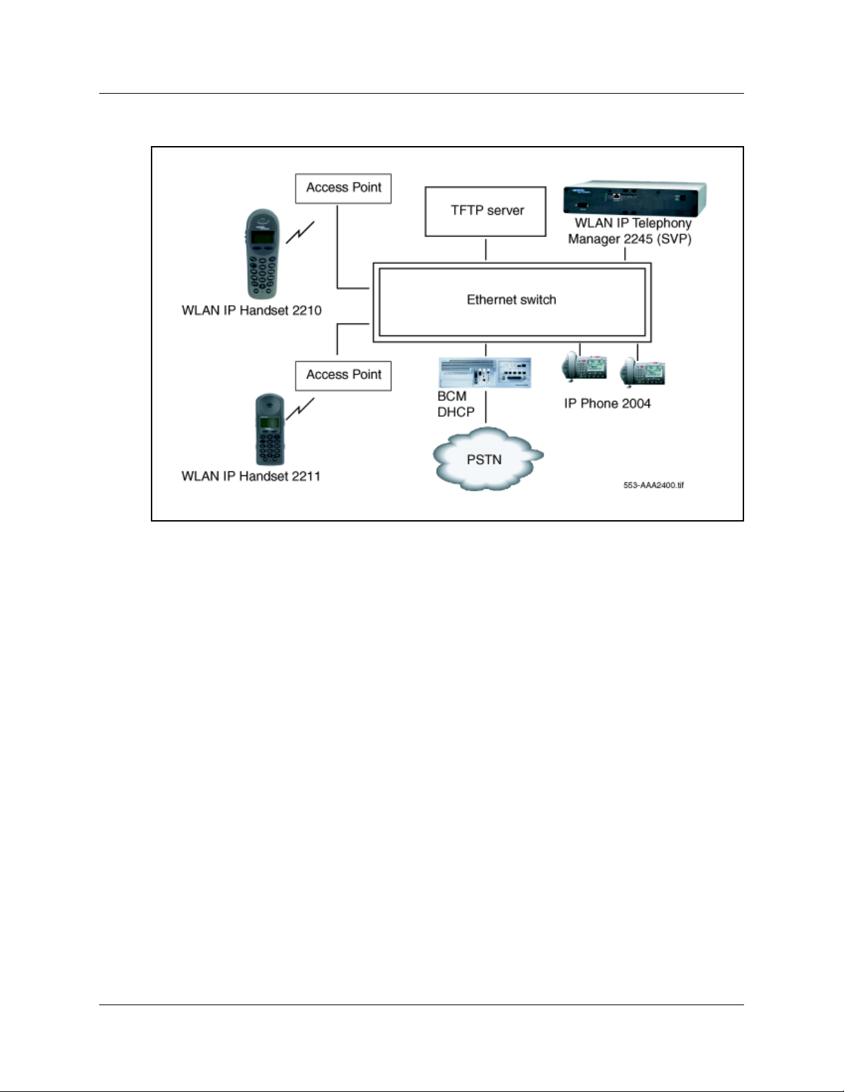
Figure 1 Basic network configuration
The basic WLAN IP Telephony network consists of the following components:
• BCM (call server)
• TFTP Server (optional)
• DHCP Server (optional)
• WLAN IP Telephony Manager 2245
• WLAN Handset 2210/2211
• Access Point (AP)
BCM
To support the WLAN Handsets 2210/2211, the BCM system must run Release 3.6.1 (patch) or
later software versions. BCM systems with 3.6 or earlier software versions must be upgraded to
support the handsets.
TFTP Server
A TFTP Server distributes firmware to the WLAN Handsets 2210/2211 and WLAN IP Telephony
Manager 2245. It can reside on a different subnet than the BCM and APs. The TFTP Server can be
located on either side of the firewall.
Overview
Page 31

If too many wireless handsets are attempting to download new firmware simultaneously, the
downloads can slow down or error messages can be returned. To reduce the number of retries and
error messages, manage the download process by staggering the times the wireless handsets
download the firmware.
The TFTP Server must be capable of supporting multiple TFTP sessions.
Nortel Networks has tested the following TFTP Servers. They are listed in order of preference.
• Nortel Networks TFTP Server (Optical Network Management System [ONMS] application)
• 3COM TFTP
• PumpkinTFTP
• SolarWinds TFTP
WLAN Handset 2210/2211 firmware upgrade
Assuming the IP address of the TFTP Server has been configured on the
WLAN Handsets 2210/2211, each time a WLAN handset is powered on, the following occurs:
31
1 The WLAN handset checks its version of firmware against the firmware on the TFTP Server,
which takes less than two seconds on a quiet network.
2 If the firmware versions are different, the WLAN handset downloads the new firmware from
the TFTP Server. This process takes about 30 seconds.
3 If the TFTP Server is offline or unreachable, the WLAN handset tries for about ten seconds
before giving up and using its existing version of firmware.
DHCP Server
For detailed DHCP Server instructions, refer to the Configuring DHCP chapter of the
Programming Operations Guide (N0008589).
DHCP is a standardized protocol that enables clients to be dynamically assigned with various
configuration parameters, such as:
• IP address
• subnet mask
• default Gateway
• other critical network configuration information
DHCP Servers centrally manage such configuration data, and are configured by network
administrators with settings that are appropriate for a given network environment.
Overview
Page 32

32
The IP-related parameters of the WLAN Handsets 2210/2211 can be configured manually or
through a DHCP Server (RFC 1541 and RFC 1533). The DHCP Server can be on either side of the
firewall, according to the site administrator’s preference. The DHCP Server is optional if the
WLAN handsets and WLAN IP Telephony Manager 2245 are statically configured.
Each wireless handset effectively uses two IP addresses in the wireless subnet. One is for the
physical set, and one is the second alias IP address that is used on the WLAN IP Telephony
Manager 2245 Server. A contiguous block of addresses, equal to the number of handsets
supported, must be marked as unavailable for distribution when you allocate addresses in a subnet
scope on the DHCP Server.
The DHCP Server can require specific configuration modifications when multiple WLANs are
connected to a single Wireless Security Switch (WSS). Refer to the documentation that
accompanies the specific WSS being used for any special DHCP configuration requirements.
The WLAN handset searches for server configuration in the options listed in Table 1. The wireless
handset uses the DHCP options listed when DHCP use is enabled.
Table 1 DHCP options
Option Meaning
1 Subnet mask
3 Default Gateway
6DNS Server
15 Domain name
66 TFTP Server
128 Site specific
151 WLAN IP Telephony Manager 2245
191 Site specific
siaddr Boot server or next server
When the patch is applied to Release 3.6, or when Release 3.7 or later is running, two new fields
appear under Global options:
• DHCP Option 66 - This can be used to specify the address of the TFTP Server. If this Option is
not present the phone will look at the Next server/ Boot server (siaddr) option for the address
of the TFTP server.
• Vendor Specific Option 43, 128, 144, 157, 191, or 251 - Only one of these options is required.
The DHCP Server encodes the Server 1 information using the same format as the IP Phone
2004. If the Server 2 information is also present in the option, it is ignored.
• DHCP Option 151 - This option contains the IP address of the WLAN IP Telephony Manager
2245. If Option 151 is not configured, the wireless handset performs a Domain Name Service
(DNS) lookup of the name “SLNKSVP2”, if Options 6 (DNS Server) and 15 (Domain Name)
are configured.
Overview
Page 33

Firewall
In many installations there will be a firewall installed between the wired and wireless parts of the
network. It is beyond the scope of this document to specify how a firewall is managed, but the
following guidelines can be used when configuring firewalls:
• The TFTP Server, DHCP Server, and Syslog Server can be anywhere in the network (that is,
• When the WLAN Handsets 2210/2211 are hosted by a BCM, the following port numbers are
33
they are not restricted to being in the same subnet as the handsets and WLAN IP Telephony
Manager 2245). From an administrative point of view, it may be more convenient to place
these components in the wired portion of the network. If a firewall is between the WLAN
Handsets 2210/2211, and the WLAN IP Telephony Manager 2245 and the servers, the firewall
will need to be configured to allow the TFTP (User Datagram Protocol [UDP] port 69 -
bidirectional) and Syslog traffic (UDP port 514 - unidirectional) and a DHCP relay agent.
used:
— UNIStim signaling uses UDP port 7000
— Media to and from the handset uses UDP ports 51000–51200.
Note: The media ports are configurable. The values shown above are the default values.
• If other Nortel call servers are used in the network (for example, BCM, MCS5100, CS2100),
the system administrator will need to determine which UDP ports are used for Realtime
Transport Protocol (RTP) and RTCP and make the appropriate provisions in the firewall.
• If third party gateways are configured in the system, the system administrator will need to
determine which UDP ports are used for RTP and RTCP and make the appropriate provisions
in the firewall.
• All media and signaling goes through the WLAN IP Telephony Managers 2245 (that is, it will
all originate from one, or a few, Media Access Control [MAC] addresses). If the firewall is
capable of filtering based on MAC address, the administrator can create a simple access
control filter based on a small number of MAC addresses.
Note: For IP Telephony firewall information, refer to the Optional VoIP trunk
configurations chapter in the 20XX IP Telephony Configuration Guide (N0008591). Also
refer to the Configuring IP Firewall Filters chapter of the Programming Operations
Guide (N0008589).
WLAN IP Telephony Manager 2245
The WLAN IP Telephony Manager 2245, also referred to as SVP II Server, is a device that
manages IP telephony network traffic on the WLAN IP Telephony system. It is required in order
to use the 11Mbit/s maximum transmission speed available in the WLAN Handsets 2210/2211.
The WLAN IP Telephony Manager 2245 acts as a proxy for the WLAN handsets. It provides a
number of services including a Quality of Service (QoS) mechanism, AP bandwidth management,
and efficient Radio Frequency (RF) link use.
Overview
Page 34

34
The WLAN IP Telephony Manager 2245 works with the APs to provide QoS on the WLAN. All
voice packets are encapsulated by the WLAN handsets. The encapsulated voice packets to and
from the WLAN handsets are handled by the WLAN IP Telephony Manager 2245 and routed to
and from the BCM.
SVP is the QoS mechanism implemented on the WLAN handsets and APs to enhance voice
quality over the wireless network. SVP gives preference to voice packets over data packets on the
wireless medium, increasing the probability that all voice packets are transmitted with minimum
delay. SVP is fully compliant with the IEEE 802.11 and 802.11b standards.
Each subnet where the WLAN handsets operate requires at least one WLAN IP Telephony
Manager 2245. One unit can process 90 simultaneous calls. If greater capacity is required, multiple
units can be used in a master-slave arrangement.
Note: The WLAN Handset 2211 uses IP multicast addresses for the Push-To-Talk (PTT)
feature. This requires that multicasting be enabled on the subnet used for the WLAN
Handset 2211 and the WLAN IP Telephony Manager 2245. Refer to the Nortel Networks
WLAN Handset 2210/2211 User Guide for more information on the PTT feature.
Physical description
The front panel of the WLAN IP Telephony Manager 2245 contains ports to connect to the
following:
•power
•LAN
• administrative computer through an RS-232 port
Status LEDs supply information about the status and activity of the WLAN IP Telephony Manager
2245. See Figure 2.
Figure 2 WLAN IP Telephony Manager 2245 front panel
• RS-232 ports - the male DB-9 connector (DTE). Provides an RS-232 connection to a terminal,
•Link LEDs
Overview
terminal emulator, or modem for system administration.
— LNKOK - lit when there is a network connection
— ACT - lit when there is system activity
Page 35

— COL - lit if there are network collisions
• NETWORK - connects the WLAN IP Telephony Manager 2245 to the wired Ethernet LAN
• ERROR LED - lit when the system has detected an error
• Status LED - indicate system error messages and status
— 1 - heartbeat
— 2 - active calls
— 3, 4, 5 - currently unused
• PWR - connects to the AC adapter supplying power to the system
Warning: Use only the provided Class II AC adapter with 24 volt (V) DC, 1 amp
(A) output.
Functional description
The WLAN IP Telephony Manager 2245 provides the following services to the WLAN Handsets
2210/2211:
35
• It acts as a proxy for every WLAN handset; that is, all Unified Networks IP Stimulus
(UNIStim) signaling and RTP media to and from the wireless handset pass through the WLAN
IP Telephony Manager 2245. Except for the initial DHCP and TFTP sessions, the wireless
handsets only communicate with the WLAN IP Telephony Manager 2245.
Each WLAN IP Telephony Manager 2245 is configured with an IP address with which all of
the wireless handsets communicate. In addition, each WLAN IP Telephony Manager 2245 is
configured with a pool of IP addresses. When a wireless handset registers with a WLAN IP
Telephony Manager 2245, the wireless handset is assigned one of the IP addresses from the
pool. All communication between this WLAN IP Telephony Manager 2245 and other devices
(BCM, IP Phones, gateways, and other wireless handsets) is always done through its pool of IP
addresses. In this sense, the WLAN IP Telephony Manager 2245 acts as a Network Address
Translation (NAT).
The WLAN IP Telephony Manager 2245 has a single physical Ethernet interface and MAC
address. Therefore, all of the IP addresses are mapped to a single MAC address.
• The WLAN IP Telephony Manager 2245 tags and untags packets with the SVP header. SVP
packets have the protocol byte of the IP header set to 0x77. SVP-compliant APs use this
proprietary tagging to give priority to tagged packets. For UDP (UNIStim and RTP) packets
going from the wireless handset to the network, the WLAN IP Telephony Manager 2245
replaces the SVP protocol number, 0x77, with the UDP number, 0x11. For packets going from
the network to the wireless handset, the protocol number is changed from 0x11 to 0x77.
There can be no Layer 3 routing in the path because packets that traverse the network between
the wireless handset and the WLAN IP Telephony Manager 2245 are not standard IP packets
(the packets use a non-standard protocol number). Therefore, the wireless handsets and
WLAN IP Telephony Managers 2245 must be in the same logical subnet.
Overview
Page 36

36
• RTP packets between the wireless telephone and the WLAN IP Telephony Manager 2245
• The WLAN IP Telephony Manager 2245 is configured with a maximum allowable number of
• There is a keep-alive packet exchange that runs between the wireless handset and the WLAN
Capacities
The WLAN IP Telephony Manager 2245 requires a CAT5 cable connection between its network
port and the Ethernet switch. The WLAN IP Telephony Manager 2245 auto-negotiates to the type
of port on the Ethernet switch and supports 10BaseT, 100BaseT, full-duplex, and half-duplex port
types.
always contain 30 milliseconds (ms) worth of voice, regardless of what has been configured
on the BCM. The WLAN IP Telephony Manager 2245 repackages the RTP packets to conform
to the size that has been configured in the BCM. This provides more efficient use of the
available RF bandwidth at the expense of slightly increased jitter and latency.
simultaneous media streams on a single AP. The WLAN IP Telephony Manager 2245 keeps
track of the number of media streams on each AP and blocks calls to and from a wireless
handset that would exceed the configured capacity.
IP Telephony Manager 2245 every 30 seconds. If the wireless handset detects the WLAN IP
Telephony Manager 2245 is unreachable, the wireless handset resets itself and attempts to
re-establish a connection with the master WLAN IP Telephony Manager 2245, where there is
more than one WLAN IP Telephony 2245 in the system.
In any subnet where wireless handsets are used, each subnet must have one or more WLAN IP
Telephony Managers 2245. A WLAN IP Telephony Manager 2245 group on a subnet consists of
one or more WLAN IP Telephony Managers 2245 and their associated wireless handsets. Only
one master WLAN IP Telephony Manager 2245 can be on a subnet.
The WLAN infrastructure, if properly deployed, can support the same capacity offered in the
BCM for IP terminals. When planning for WLAN set deployment, follow standard BCM IP
terminal engineering practices. When planning your WLAN infrastructure deployment, follow
your AP vendor’s standard voice deployment site survey practices.
WLAN IP Telephony Manager 2245 firmware upgrade
When a WLAN IP Telephony Manager 2245 reboots or is manually reset by the operator, the
following occurs:
1 The WLAN IP Telephony Manager 2245 checks its version of firmware against the version on
the TFTP Server.
2 If the firmware versions are different, the WLAN IP Telephony Manager 2245 downloads the
new firmware.
Overview
Page 37

37
Feature Packaging/Set Emulation Model, IT Type and Release Number
The WLAN Handsets 2210/2211 appear to the BCM as a standard IP Phone 2004.
The WLAN Handsets 2210/2211 have the following assignments:
• IT TYPE: 0x02
• Release Number 2210: 0x06
• Release Number 2211: 0x07
• Manufacturing ID: 30
• Color Code: 66
• DHCP Class Identifier: "Nortel-i2210-A" or "Nortel-i2211-A"
• PEC Code: NTTQ4010 for the 2210 and NTTQ5010 for the 2211
Roaming and handover
Roaming is the ability of the wireless handset to go anywhere in the WLAN Extended Service Set
(ESS) RF signal coverage area and to make and receive calls. Handover is the ability of the
wireless handset to maintain an active call without interruption while moving within a WLAN ESS
RF signal coverage area. This means that the wireless handset hands over the WLAN RF signal
from AP to AP without interrupting the data stream.
APs on the same subnet
The WLAN Handsets 2210/2211 can perform handover and roaming across SVP-compliant APs
that reside on the same subnet as the wireless handset and WLAN IP Telephony Manager 2245
group. Refer to Table 8 on page 77 for a list of SVP-compliant APs.
APs on different subnets using WSS
If you use Nortel Networks WSS 2250/2270 and Nortel Networks Access Ports 2230, both
operating in Layer 3 mode, the WLAN Handsets 2210/2211 can perform roaming and handover
across Access Ports 2230 on different subnets. The WSS 2270 operating in Layer 3 mode is on the
same subnet as the WLAN IP Telephony Manager 2245 group. The WSS 2270 allows the wireless
handset to retain its original IP address, whether the IP address was configured statically or
obtained by DHCP. This means that roaming and handover can occur across Access Ports 2230
placed on any subnet.
Note: The WSS 2270 must be running version 2.0.71.0 (or later) software.
Overview
Page 38

38
Mobility across different subnets when using DHCP
If a WSS is not in use, and the IP address of the wireless handset has been acquired through
DHCP, the wireless handset must be powered down and powered up when entering a new subnet.
This enables functionality of the wireless handset when entering the WLAN RF signal coverage
area of a different WLAN IP Telephony Manager 2245 group on a different subnet. Normal
functionality returns once the wireless handset:
• establishes communication within the Extended Service Set ID (ESSID) of the new WLAN
• obtains another IP address from the DHCP Server
• checks in with the group master
If the wireless handset is configured to use the ESSID of the new WLAN, it automatically
discovers the ESSID of the APs operating in broadcast mode.
Table 2 summarizes the roaming and handover capabilities.
Table 2 Roaming and handover capabilities summary
IP address WSS in use Roaming capability Handover capability
Static No No No
Static Yes Yes Yes
DHCP No Yes, if the wireless
DHCP Yes Yes Yes
Access Point
The 802.11b APs provide the connection between the wired Ethernet LAN and the wireless
(802.11) LAN. APs work in all markets and must be positioned in all areas where the WLAN
handsets are used. The number and placement of APs affects the coverage area and capacity of the
WLAN IP Telephony system. Typically, the requirements for use of WLAN Handsets 2210/2211
are similar to those of other wireless data devices.
The APs must be SVP-compliant to support QoS. For a list of supported APs, refer to Appendix A:
Compatible Access Points on page 77.
When a user on an active call is moving about, the call switches from one AP to another in the
subnet. This changeover is transparent to the user.
No
handset is
power-cycled between
subnets.
Overview
Page 39

It is essential to know where to install the APs to provide effective coverage for the WLAN
handsets. The first step is to define exactly where the coverage is needed, which requires a site
survey. Refer to “Appendix D: Provisioning” on page 113 for information on site planning.
Tips: A site survey must be performed before installing a wireless LAN. Nortel Networks
also recommends a site survey when an existing network structure is modified or when
physical changes are made to a site.
Nortel Networks recommends the use of the Nortel Networks Site Survey Tool to perform
the site survey.
Network planning
.It is necessary to ensure that all connections and interfaces for the IP Telephony network be
configured as full-duplex. Duplex mismatches anywhere on the WLAN can cause the wireless IP
Telephony system not to function normally.
39
IP address planning
The WLAN IP Telephony Manager 2245, the optional WLAN Application Gateway 2246, and
each of the wireless handsets and APs associated with them, requires an IP address.
Note: The master WLAN IP Telephony Manager 2245 must have an IP address statically
configured. If using DHCP for the rest of the network, the DHCP Server must have the
static IP address of the master WLAN IP Telephony Manager 2245 configured on it. If
using DNS, the DNS Server must have the static IP address of the master WLAN IP
Telephony Manager 2245 configured on it.
The wireless handsets can be configured to use DHCP or can be assigned a static IP address. If
there is no DHCP Server, the system administrator must determine what IP addresses are to be
used for static addressing. As well, whether static IP addressing or DHCP is used, a pool of alias IP
addresses must be configured on the WLAN IP Telephony Manager for the use of the wireless
handsets. Ensure that the pool of alias IP addresses is reserved exclusively for the use of the
wireless handsets.
Refer to WLAN IP Telephony Manager 2245 configuration on page 45 for information on
configuring a static IP address on a WLAN IP Telephony Manager 2245. Refer to “Configuring
the network” on page 48 for information on configuring a static IP address for a WLAN
Application Gateway 2246. Refer to IP Address menu on page 63 for information on configuring a
static IP address on the WLAN Handsets 2210/2211. Refer to the vendor-specific documentation
for information on assigning IP addresses to the APs.
Tip: Record the static IP address assignments and store them in a safe place.
Overview
Page 40

40
IP addressing with DHCP
A pool of alias IP addresses must be configured on the WLAN IP Telephony Manager 2245 for the
use of the wireless handsets. Refer to “Functional description” on page 35 for information on IP
addresses on the WLAN IP Telephony Manager 2245.
The use of a 22-bit subnet mask provides IP addresses for approximately 500 wireless handsets
(1024 nodes). Allocate a pool of an equal number of IP addresses on the DHCP Server and WLAN
IP Telephony Manager 2245 for the wireless handsets.
For example:
142.223.204.1 to 142.223.205.254 are allocated on the DHCP Server for the use of the wireless
handsets.
142.223.206.1 to 142.223.207.254 are configured on the WLAN IP Telephony Manager for IP
aliases for the wireless handsets.
Ensure that all these IP addresses are reserved on the DHCP Server for the use of the wireless
handsets and not assigned to any other device.
Programming Records
Use the WLAN Programming Records spreadsheet (a Microsoft ExcelTM file) to record settings for
each handset. The spreadsheet is located on the BCM documentation CD. Use the recorded
settings when you configure the handsets. Refer to WLAN Handsets 2210/2211 configuration on
page 55 for instructions on configuring the handsets.
Overview
Page 41

WLAN IP Telephony Manager 2245 installation
This section explains how to install the WLAN IP Telephony Manager 2245.
For an overview of the WLAN IP Telephony Manager 2245, refer to “WLAN IP Telephony
Manager 2245” on page 33.
For information on configuring the WLAN IP Telephony Manager 2245, refer to “WLAN IP
Telephony Manager 2245 configuration” on page 45.
Tasks:
• Prepare to install the WLAN IP Telephony Manager 2245 (“Preparing to install the WLAN IP
Telephony Manager 2245” on page 41)
• Mounting the WLAN IP Telephony Manager 2245 (“Mounting the WLAN IP Telephony
Manager 2245” on page 42)
• Connect to the Local Area Network (LAN) (“Connecting to the LAN” on page 43)
• Connect the power (“Connecting the power” on page 43)
41
• Prepare to install the WLAN IP Telephony Manager 2245 (“Preparing to install the WLAN IP
Telephony Manager 2245” on page 41)
• Mounting the WLAN IP Telephony Manager 2245 (“Mounting the WLAN IP Telephony
Manager 2245” on page 42)
• Connect to the Local Area Network (LAN) (“Connecting to the LAN” on page 43)
• Connect the power (“Connecting the power” on page 43)
Preparing to install the WLAN IP Telephony Manager 2245
Required materials
Each WLAN IP Telephony Manager 2245 is shipped with one Class II AC adapter with 24 volt
(V) DC, 1 amp (A) output.
The following equipment must be provided by the customer:
• Power outlet(s) – must accept the provided AC adapter.
• Choose one of the following:
— Plywood backboard space – the WLAN IP Telephony Manager 2245 is designed to be
wall-mounted to ¾” plywood securely screwed to the wall.
— Optional WLAN IP Telephony Manager 2245 rack-mount kit (must be ordered
separately), containing mounting plates and screws.
WLAN IP Telephony Manager 2245 installation
Page 42

42
• Screws – used to mount the WLAN IP Telephony Manager 2245 to the wall. Four 3/4-inch #8
panhead wood screws (or similar devices) are required.
• CAT5 cable with an RJ-45 connector for the WLAN IP Telephony Manager 2245 – provides a
connection to the Ethernet switch.
• DB-9 female null-modem cable – required for initial configuration of the WLAN IP
Telephony Manager 2245.
Note: The WLAN IP Telephony Manager 2245 requires a maximum distance of 325 feet
(100 meters) from the Ethernet switch.
Pre-installation checklist
Ensure that the following requirements have been met prior to installation:
• The location is adequate and power is available.
• Access Points (APs) are SVP-compatible and coverage is adequate.
• A dedicated line is available for remote modem access, if needed.
• The telephone system administrator is on-site to program the existing telephone system.
Mounting the WLAN IP Telephony Manager 2245
The WLAN IP Telephony Manager 2245 can be mounted either vertically or horizontally.
The rack-mount kit is designed for mounting the WLAN IP Telephony Manager 2245 in a
standard 19-inch rack and contains the following equipment:
• Mounting plates – two for each WLAN IP Telephony Manager 2245 to be mounted.
• Screws – four rack-mount screws for each WLAN IP Telephony Manager 2245 to be mounted.
Wall-mounting the WLAN IP Telephony Manager 2245
1 Use a 1/8-inch drill bit to drill four pilot holes, on 1.84-inch by 12.1-inch centers
(approximately equivalent to 1 13/16-inch by 12 1/8-inch).
2 Insert the 3/4-inch #8 screws in the pilot holes and tighten, leaving a
1/8-inch to 1/4-inch gap from the wall.
3 Slide the WLAN IP Telephony Manager 2245 over the screws until the WLAN IP Telephony
Manager 2245 drops into place in the keyhole openings of the flange.
4 Tighten screws fully.
WLAN IP Telephony Manager 2245 installation
Page 43

Rack-mounting the WLAN IP Telephony Manager 2245
1 Remove the corner screws from the WLAN IP Telephony Manager 2245.
2 Screw the U-shaped end (round screw holes) of the two mounting plates to the WLAN IP
Telephony Manager 2245.
3 Screw the other end of the two mounting plates (oblong screw holes) to the rack.
4 Repeat steps 1-3 for each additional WLAN IP Telephony Manager 2245. The mounting plate
is designed to provide the correct minimum spacing between units. When mounting multiple
units, stack the units in the rack as closely as possible.
Connecting to the LAN
Use an RJ-45 cable to connect the NETWORK port on the WLAN IP Telephony Manager 2245
to the connecting port on the Ethernet switch.
43
Connecting the power
1 Connect the power plug from the AC adapter to the jack labeled PWR on the WLAN IP
Telephony Manager 2245.
Warning: Use only the provided Class II AC adapter with output 24V DC, 1A.
2 Plug the AC adapter into a standard AC outlet (that is, one that is compliant with local power
supply) to supply power to the WLAN IP Telephony Manager 2245.
The system cycles through diagnostic testing and the LEDs blink for approximately one
minute.
3 When the system is ready for use, verify the following:
•The ERROR LED is off.
• Status 1 is blinking.
Removing a WLAN IP Telephony Manager 2245
1 Disconnect the power cables and LAN cables from the WLAN IP Telephony Manager 2245.
2 Remove the failed device from the wall or rack mount.
WLAN IP Telephony Manager 2245 installation
Page 44

44
WLAN IP Telephony Manager 2245 installation
Page 45

WLAN IP Telephony Manager 2245 configuration
This section explains how to configure the WLAN IP Telephony Manager 2245 (SVP II Server).
For an overview of the WLAN IP Telephony Manager 2245, refer to “WLAN IP Telephony
Manager 2245” on page 33.
For information on installing the WLAN IP Telephony Manager 2245, refer to “WLAN IP
Telephony Manager 2245 installation” on page 41.
Tasks:
• Connect to the WLAN IP Telephony Manager 2245 (“Connecting to the WLAN IP Telephony
Manager 2245” on page 45)
• Configure the WLAN IP Telephony Manager 2245 (“Configuring the WLAN IP Telephony
Manager 2245” on page 47)
• Change the password (“Changing the password” on page 52)
• Save the configuration (“Saving the configuration” on page 53)
45
• Check system status (“Checking the system status” on page 54)
Connecting to the WLAN IP Telephony Manager 2245
The initial connection to the WLAN IP Telephony Manager 2245 must be made through a serial
connection to establish the IP address of the WLAN IP Telephony Manager 2245 and the
maximum number of active calls per access point.
Further configuration and administration can be performed at a later time through a Telnet
connection.
The Telnet method of connection is also used for routine maintenance of the WLAN IP Telephony
Manager 2245.
Security Note: Nortel Networks recommends that you change the default password
!
immediately for security reasons (see “Changing the password” on page 52).
Connecting through a serial port
1 Connect the WLAN IP Telephony Manager 2245 to the serial port of a terminal or PC using a
DB-9 female, null-modem cable.
2 Run a terminal emulation program (such as HyperTerminal™), or use a VT-100 terminal with
the following configuration:
WLAN IP Telephony Manager 2245 configuration
Page 46

46
— Bits per second: 9600
— Data bits: 8
— Parity: None
— Stop bits: 1
— Flow control: None
Note: If using Windows 2000, Service Pack 2 must be installed to enable the use of
HyperTerminal™.
3 Press Enter to display the login screen.
4 Enter the default login name (admin) and the default password (admin).
Programming note: The login name and password are case-sensitive.
The NetLink SVP-II System menu appears. See
NetLink SVP-II System menu on page 47.
Connecting through a Telnet session
1 Run a Telnet session to the IP address of the WLAN IP Telephony Manager 2245.
2 Enter the login name and the password.
Programming note: The login name and password are case-sensitive.
The NetLink SVP-II System menu appears. See NetLink SVP-II System menu on page 47.
WLAN IP Telephony Manager 2245 configuration
Page 47
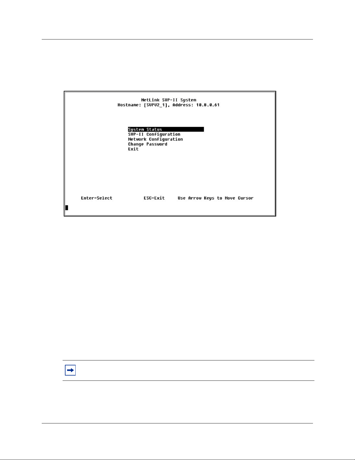
NetLink SVP-II System menu
The NetLink SVP-II System menu is shown in Figure 3.
Figure 3 NetLink SVP-II System menu
47
The NetLink SVP-II System menu contains the following options:
• System Status – view error messages, status of operation, and firmware code version.
• SVP-II Configuration – set the mode and reset the system.
• Network Configuration – set network configuration options including IP address and
hostname.
• Change Password – change the password for the WLAN IP Telephony Manager 2245.
Configuring the WLAN IP Telephony Manager 2245
Configuration of the network must be done before the WLAN IP Telephony Manager 2245 can be
configured. Therefore, the WLAN IP Telephony Manager 2245 is configured initially on the
Network Configuration screen. This initial configuration must be performed through the serial
port to configure the IP address and the maximum number of active calls per access point.
Tips: Nortel Networks recommends that you complete the initial network configuration
through the serial connection.
WLAN IP Telephony Manager 2245 configuration
Page 48

48
The WLAN IP Telephony Manager 2245 is then configured on the SVP-II Configuration screen.
The mode of the WLAN IP Telephony Manager 2245 is configured here. This screen is also used
to lock the WLAN IP Telephony Manager 2245 for maintenance and reset the WLAN IP
Telephony Manager 2245 after maintenance.
The WLAN IP Telephony Manager 2245 automatically locks for maintenance if the IP address is
changed. When a Maintenance Lock occurs, the WLAN IP Telephony Manager 2245 must be
reset upon exit. All active calls are terminated during a reset.
Configuring the network
1 Select Network Configuration from the NetLink SVP-II System menu.
The Network Configuration screen appears (see Figure 4).
Figure 4 Network Configuration screen
2 Configure the following fields with information provided by the network administrator:
• IP Address – enter the complete IP address for the WLAN IP Telephony Manager 2245,
including digits and periods.
Note: If this WLAN IP Telephony Manager 2245 is the master, it must have a static IP
address. Do not use DHCP to assign the IP address of the master WLAN IP Telephony
Manager 2245. Slave WLAN IP Telephony Managers 2245, in a multiple WLAN IP
Telephony Manager 2245 environment, can have their IP addresses assigned by DHCP.
• Hostname – optional field. Change the hostname of this WLAN IP Telephony Manager
2245, if desired. Hostname is for identification purposes only.
Programming note: Spaces cannot be entered in this field.
•
Subnet mask – the subnet mask of the subnet.
• Default Gateway – the default gateway for the subnet.
WLAN IP Telephony Manager 2245 configuration
Page 49

49
• SVP-II TFTP Download Master – the IP address of the TFTP Server where the firmware
update files are saved. Enter one of the following:
— NONE – disables this function
— TFTP server IP address – IP address of the TFTP Server that transfers firmware
updates to the WLAN IP Telephony Manager 2245.
• Primary DNS Server, Secondary DNS Server, DNS Domain – used to configure DNSs.
Obtain the settings from the network administrator.
Optionally, enter DHCP. This enables the DHCP client in the WLAN IP Telephony
Manager 2245 to attempt to automatically obtain a valid IP address from the DHCP
Server. The DHCP setting is only valid when the IP address is obtained from DHCP.
• WINS Server – the IP address of the Windows Name Services (WINS) Server. Obtain the
settings from the network administrator.
Optionally, enter DHCP. This enables the DHCP client in the WLAN IP Telephony
Manager 2245 to attempt to automatically obtain a valid IP address from the DHCP
Server. The DHCP setting is only valid when the IP address is obtained from DHCP.
When WINS is configured, the WLAN IP Telephony Manager 2245 can translate
hostnames to IP addresses. This means that using Telnet, the WLAN IP Telephony
Manager 2245 can be accessed using its hostname rather than its IP address.
• Syslog Server – the IP address of the server where the system logs are written for the
WLAN IP Telephony Manager 2245. If a Syslog Server is configured, a message is sent to
the Syslog Server when an alarm is generated. Enter one of the following:
— NONE – disables this function
— IP address of the Syslog Server
• Maintenance Lock – indicates if the WLAN IP Telephony Manager 2245 is in
Maintenance Lock mode.
• SendAll – in a system with multiple WLAN IP Telephony Managers 2245, the SendAll
option is provided to speed configuration and ensure identical settings. The S=SendAll
option enables configuration parameters of the selected field to be sent to every WLAN IP
Telephony Manager 2245 on the LAN. SendAll can only be used after the IP address is
configured on each WLAN IP Telephony Manager 2245 using a serial connection. If
identical configuration parameters are to be used for all WLAN IP Telephony Managers
2245, configure only the IP address and custom hostname (if desired) on each WLAN IP
Telephony Manager 2245 using the initial serial connection. Then connect through the
LAN to this WLAN IP Telephony Manager 2245 and use SendAll to transmit identical
configuration options of each field to all WLAN IP Telephony Managers 2245
Note: If SendAll is used on the system, all passwords must be identical. Do not change
the password at the initial configuration if the SendAll option will be used. Use the default
password and change it globally, if desired, after a LAN connection is established for all
WLAN IP Telephony Managers 2245. If you want independent administration of each
WLAN IP Telephony Manager 2245, the passwords can be set during initial
configuration.
WLAN IP Telephony Manager 2245 configuration
Page 50

50
3 Reset the WLAN IP Telephony Manager 2245 in order to save the configuration parameters.
Follow the steps in “Saving the configuration” on page 53 to save the configuration.
Configuring the SVP-II
1 Select SVP-II Configuration from the NetLink SVP-II System menu to configure additional
options for WLAN IP Telephony Manager 2245.
The SVP-II Configuration screen appears (see Figure 5).
Figure 5 SVP-II Configuration screen
2 Configure the following fields with information provided by the network administrator:
• Phones per Access Point – enter the number of simultaneous calls supported for the type
of AP. AP specifications are described in Appendix A: Compatible Access Points on page
77.
• 802.11 Rate – select Automatic to allow the wireless handset to determine its rate (up to
11Mbit/s). Select 1MB/2MB to limit the transmission rate between the wireless handsets
and APs.
• SVP-II Master – the IP address of the master of the WLAN IP Telephony Manager 2245
group must be identified. Select one of the following identification options:
— Enter the IP address of the master of the WLAN IP Telephony Managers 2245 in each
WLAN IP Telephony Manager 2245 group. Include the periods used in the IP address.
—Enter DHCP. Ensure that the IP address of the master WLAN IP Telephony Manager
2245 has been configured in the DHCP Server and configure the other WLAN IP
Telephony Managers 2245 to obtain the information from the DHCP Server.
—Enter DNS. Ensure that the IP address of the master WLAN IP Telephony Manager
2245 has been configured in the DNS Server and configure the other WLAN IP
Telephony Managers 2245 to retrieve this information from the DNS Server.
WLAN IP Telephony Manager 2245 configuration
Page 51

51
• First Alias IP Address/Last Alias IP Address – enter the range of IP addresses that this
WLAN IP Telephony Manager 2245 can use when acting as a proxy for the wireless
handsets.
Programming note: All alias addresses must be on the same subnet as the WLAN IP
Telephony Manager 2245. The IP addresses cannot be duplicated on other subnets or
WLAN IP Telephony Managers 2245. There is no limit to the number of IP addresses that
can be assigned, but the capacity of each WLAN IP Telephony Manager 2245 is 500
wireless handsets.
• SVP-II Mode – select NetLink IP.
• Ethernet link – select auto-negotiate unless there is a need to specify the link speed.
• System Locked – use this option to take the system down for maintenance. The default is
N (No). Select Y (Yes) to prevent any new calls from starting. Enter N to restore normal
operation.
• Maintenance Lock – the system automatically sets this option to Y after certain
maintenance activities that require reset, such as changing the IP address. Maintenance
Lock prevents any new calls from starting. The administrator cannot change this option; it
is automatically set by the system. Reset the system at exit to clear Maintenance Lock.
• Reset – if this option is selected, a prompt appears to reset the WLAN IP Telephony
Manager 2245 when exiting the SVP-II Configuration screen.
• Reset all SVP servers – if this option is selected, all WLAN IP Telephony Managers 2245
on the subnet are reset.
3 Reset the WLAN IP Telephony Manager 2245 in order to save the configuration parameters.
Follow the steps in “Saving the configuration” on page 53 to save the configuration.
Note: Resetting the WLAN IP Telephony Manager 2245 terminates any calls in progress.
Nortel Networks recommends making configuration changes (can involve locking the
system) and resetting the WLAN IP Telephony Manager 2245 during off-hours.
Note: Nortel Networks recommends setting the Keep DN Alive feature, as well as call
forward, during the lock-down and reset periods.
WLAN IP Telephony Manager 2245 configuration
Page 52

52
Changing the password
1 Select Change Password from the NetLink SVP-II System menu.
The Change Password screen appears. See Figure 6.
Figure 6 Change Password screen
2 Enter the old password.
3 Enter the new password.
The password parameters are as follows:
• must be more than four characters in length
• first character must be a letter
• other characters can be letters or numbers
• dashes, spaces, and punctuation marks are not allowed (alphanumeric only)
4 Confirm the new password.
5 Select Set Password and press Enter. Alternatively, press the S key on the keyboard.
6 Reset the WLAN IP Telephony Manager 2245 in order to save the configuration parameters.
Follow the steps in “Saving the configuration” on page 53 to save the configuration.
Tips: Record the password and keep it in a safe place. If the password is forgotten, contact
Nortel Networks for assistance.
WLAN IP Telephony Manager 2245 configuration
Page 53

Saving the configuration
Once any change is made to the configuration of the WLAN IP Telephony Manager 2245, the
system must be re-booted/reset for the change to take effect. You can make all configuration
changes necessary on the Network Configuration, SVP-II Configuration, and Change
Password screens, and then reset the system to save changes.
Reset the system in one of two ways:
• Reset the system from the SVP-II Configuration screen:
a Select Reset from the SVP-II Configuration menu.
A prompt appears asking if the configuration is to be saved (Are you sure <Y/N>?).
Figure 7 SVP-Configuration screen with reset prompt
53
b Enter Y to save changes, or N to disregard changes.
• Power off the WLAN IP Telephony Manager 2245, then power it on again.
Note: If Maintenance Lock is on, you can exit from the configuration screens and from
Telnet with no warning that you must reset the system. However, if a user tries to make a
call from one of the IP Handsets 2210/2211, he or she will see “SYSTEM LOCKED” on
the LCD of the handset. Users cannot make calls until the WLAN IP Telephony Manager
2245 is reset.
Once the reset is complete, you will see the screen shown in Figure 8 on page 54 (Telnet
connection). During reset, the WLAN Handsets 2210/2211 display shows “SVP has no response”,
then “No Net”. The handsets beep when the WLAN IP Telephony Manager has re-booted.
WLAN IP Telephony Manager 2245 configuration
Page 54

54
Figure 8 Telnet screen after reset
Checking the system status
Information about system alarms and network status is obtained through the System Status menu
screen. For information on the System Status menu screen, refer to “Troubleshooting” on page
71.
WLAN IP Telephony Manager 2245 configuration
Page 55

WLAN Handsets 2210/2211 configuration
This section describes the WLAN Handsets 2210/2211 and explains how to configure them.
For an overview of the WLAN handsets, refer to “WLAN Handsets 2210/2211” on page 55.
Tasks:
• Configure WLAN Handset 2210 and WLAN Handset 2211 (“Configuring the WLAN Handsets
2210/2211” on page 60)
• Program the features on the WLAN handsets (“Programming the WLAN Handsets 2210/2211”
on page 70)
• Test the WLAN handsets (“Appendix C: Testing the WLAN Handsets 2210/2211” on page
109)
Note: The WLAN Handsets 2210/2211 require special configuration to enable them to
communicate with the optional WLAN Application Gateway 2246. Ensure that these
settings are correct. Refer to Opening and using the Admin Menu on page 61.
55
WLAN Handsets 2210/2211
The WLAN Handsets 2210/2211 use VoIP technology on IEEE 802.11-compliant WLANs. APs
use radio frequencies to transmit signals to and from the WLAN handsets.
Employees carry WLAN handsets to make and receive calls as they move throughout the building.
The WLAN handsets are used only on the premises; they are not cellular phones. Just like wired
telephones, the WLAN handsets receive calls directly, receive transferred calls, transfer calls to
other extensions, and make outside and long-distance calls (subject to corporate restrictions).
The radio frequencies use Spread Spectrum radio technology, which comes in two variations:
• Direct Sequence (DS)
• Frequency Hopping (FH)
The WLAN Handsets 2210/2211 use Direct Sequence Spread Spectrum (DSSS) radio technology
to optimize bandwidth and minimize jitter on the WLAN IP Telephony network. The WLAN
handsets are not compatible with FH.
The WLAN Handsets 2210/2211 on an 802.11b network operate at a transmission rate of up to
11 Mbit/s in a DSSS system.
WLAN Handsets 2210/2211 configuration
Page 56

56
WLAN Handsets 2210/2211 functions
Table 3 describes the handset functions available during different states.
Table 3 Handset functions available in idle and offhook states
Idle state Offhook state
FCN key:
•Mute
•Hold
• Goodbye
• Directory
•Inbox
• Outbox
•Quit
•Copy
LINE key:
• Intercom
• Intercom
• 3, 4, 5, and 6 are
system-programmed
features
The functions available are
the same as those on the IP
Phone 2004, with the
exception of handsfree.
Language
The menus and screens of the WLAN Handsets 2210/2211 display in English only. International
characters are supported for BCM prompts, depending on the market profile. BCM-based prompts
display in English, French, and Spanish.
Wired Equivalent Privacy
The WLAN Handsets 2210/2211 support Wired Equivalent Privacy (WEP) as defined by the
802.11b specification. WEP increases the security of the wireless LAN to a level similar to a wired
Ethernet LAN. WEP is turned on and off using the APs.
Loss of signal
If a wireless handset is out of range of all APs, it waits 20 seconds for a signal to return. If a signal
is not re-acquired within 20 seconds, the wireless handset loses connection to the BCM and any
calls are dropped. When the wireless handset comes back into range of an AP, it re-establishes a
connection to the BCM and goes through the system registration process.
Note: If a wireless handset is out of contact with the system for four seconds during the
UNIStim messaging process (worst case scenario), then a UNIStim failure could result.
This can cause the wireless handset to lose the UNIStim association with the BCM.
WLAN Handsets 2210/2211 configuration
Page 57

Codecs
The WLAN Handsets 2210/2211 are compatible with the G.711 and G.729a/ab codecs. No
configuration is required on the wireless handsets.
If the WLAN Handsets 2210/2211 are registered to the same BCM as IP Phone 200x sets, then the
system administrator must configure only the subset of codecs that is supported by both the
WLAN Handsets 2210/2211 and the IP Phone 200x sets.
If it is necessary for the IP Phone 200x to use a codec that is not supported on the WLAN Handsets
2210/2211 (for example, G.723.1), the wireless handsets must be configured on their own separate
node.
Jitter buffer
The WLAN Handsets 2210/2211 do not support a configurable jitter buffer. If they receive the
Jitter Buffer Configuration UNIStim message, the command is ignored. Any
adjustment to the jitter buffer setting has no effect on the handsets.
57
RTP and RTCP
The WLAN Handsets 2210/2211 do not support RTCP. If RTCP packets are sent to the phone
(these are actually sent to the WLAN IP Telephony Manager 2245), they are discarded. When the
handsets are queried for their RTCP statistics, the handsets respond with 0 for jitter, 0 for latency
and 0 for packet loss.
IP Phone 2004 mapping
The WLAN Handsets 2210/2211 emulate the IP Phone 2004. All IP Phone 2004 functions and
messaging features are supported, where possible. The speakerphone function and functions that
require use of the volume keys are not supported. See Feature limitations on page 75 for more
information on the limitations of the WLAN Handsets 2210/2211.
The large screen area of the IP Phone 2004 and its numerous keys are mapped onto the smaller
screen and fewer buttons of the wireless handsets. The button mapping from the IP Phone 2004 to
the WLAN Handsets 2210/2211 is designed to preserve nearly all of the functionality of the IP
Phone 2004 within a small, mobile device.
Feature and key assignment
The line keys of the IP Phone 2004 are numbered 1, 2, 3, 4, 5, and 6, and are situated to the left and
right of the display screen (see Figure 9 on page 58). These IP Phone 2004 line keys are mapped to
the LINE button on the WLAN Handsets 2210/2211 (see Figure 10 on page 59).
WLAN Handsets 2210/2211 configuration
Page 58

58
Figure 9 IP Phone 2004
WLAN Handsets 2210/2211 configuration
Page 59

Figure 10 WLAN Handset 2210
59
The IP Phone 2004 has several fixed feature keys. The WLAN Handsets 2210/2211 support the
eight features that are suitable to a mobile user through the Function (FCN) key on the wireless
handset. When FCN is pressed, a screen that lists the features and the assigned keys appears. Press
FCN again to display a second screen that lists more features and their assigned keys. Refer to the
Nortel Networks WLAN Handset 2210/2211 User Guide for the list of features/functions available
using the FCN key.
If a third-party application has been assigned to a key, that information appears on the feature list.
The Line keys on the WLAN Handsets 2210/2211 correspond to the six buttons on the IP Phone
2004. Refer to the Nortel Networks WLAN Handset 2210/2211 User Guide for details.
WLAN Handsets 2210/2211 configuration
Page 60

60
Table 4 lists the keys of the IP Phone 2004 (default settings) and the corresponding key sequences
on the wireless handsets.
Table 4 IP Phone 2004 mapping to the wireless handsets
Wireless handset key
IP Phone 2004 key Feature
1 Call forward Line + 6
2 Conference Line + 5
3 Last number redial Line + 4
4 Page - General Line + 3
5 Intercom Line + 2
6 Intercom Line + 1
Mute Mute Fcn + 1
Hold Hold Fcn + 2
Goodbye Goodbye Fcn + 3
Directory Directory Fcn + 4
Inbox Inbox Fcn + 5
Outbox Outbox Fcn + 6
Quit Quit Fcn + 7
Copy Copy Fcn + 8
Softkey Context-specific Softkey A
Softkey Context-specific Softkey B
Softkey Context-specific Softkey C
Softkey Context-specific Softkey D
sequence
Configuring the WLAN Handsets 2210/2211
WLAN handset configuration is performed after the WLAN IP Telephony Manager 2245 has been
installed and configured. The steps to configure a WLAN handset must be performed for each
wireless handset.
Provision the WLAN Handsets 2210/2211 on the BCM system in the same manner as an IP Phone
2004. Ensure you have the BCM firmware download completed before configuring the handsets.
For detailed information, refer to IP Line: Description, Installation and Operation
(553-3001-365).
Note: The WLAN Handset 2210/2211 is identified as an IP Phone 2004 in the IP
Terminal List when the set is offline.
WLAN Handsets 2210/2211 configuration
Page 61
The Admin Menu contains configuration options that are stored locally on each wireless handset.
Every wireless handset is independent. If the default settings are not appropriate, the Admin
options must be configured in each handset that requires different settings.
Opening and using the Admin Menu
1 With the wireless handset powered OFF, simultaneously press and hold the Power On/Start
Call and Power Off/End Call keys.
2 Release the Power On/Start Call key, then release the Power Off/End Call key. The first
option on the Admin Menu appears.
Note: If an Admin Password has been configured, the display requires its entry before
opening the Admin Menu. If no password is configured, the display proceeds directly into
the Admin Menu.
3 Press the Up and Down keys on the left side of the set to scroll through the menu options.
4 Press the OK softkey to change the selected option.
5 Press the Up softkey to return to the previous menu level.
61
6 Press the Exit softkey to exit the menus.
Tip: An asterisk (*) next to an option indicates that it is selected.
Making an alphanumeric string entry
1 On the keypad, press the OK button to change the entry.
2 Press the number key of the desired letter.
The number appears.
3 Press the number key again to display the first letter associated with that key.
4 Press the key again to scroll through the letters associated with that key.
Example: if 2 is pressed repeatedly, 2, A, B, C, a, b, and c are displayed.
Table 5 shows the keys to use to enter non-numeric characters or other characters not represented
on the keypad.:
Table 5 Keys to enter non-numeric characters (Sheet 1 of 2)
To enter... Press
. - _! # $ % & ‘ ( ) , : ; / \ = @ ~ 1
Space 0
WLAN Handsets 2210/2211 configuration
Page 62

62
Table 5 Keys to enter non-numeric characters (Sheet 2 of 2)
To enter... Press
Q q 7
Z z 9
When the correct entry appears, press the right arrow to move to the next character. Repeat for
each digit/letter of the entry.
Press the Save softkey to save the entry and return to the menu. Press the Cncl key to abort
and return to the menu without saving any changes.
Admin Menu options
Table 6 lists the Admin Menu options. Detailed descriptions of each option follow the table.
Note: The IP Handsets 2210/2211 configuration menu can differ from the items listed in
Table 6 if the firmware has not been updated. Refer to the guide that accompanies the
handset for configuration settings until the firmware is updated.
The default settings are indicated with an asterisk (*).
Table 6 Admin Menu options (Sheet 1 of 2)
Admin menu
option 2nd level 3rd level 4th Level
IP Address * Use DHCP
Static IP Phone IP
TFTP Server IP
OAI Server IP
Default Gateway
Subnet Mask
SVP Server IP
Server 1 IP
Server 1 Port
Server 2 IP
Server 2 Port
ESS ID Static Entry
* Learn Once
Learn Always
License
Management
Set Current
WLAN Handsets 2210/2211 configuration
Page 63

Table 6 Admin Menu options (Sheet 2 of 2)
Admin menu
option 2nd level 3rd level 4th Level
Restore Defaults
Site Survey Mode
Regulatory Domain
Security * None
WEP Authentication Open System Shared Key
WEP On/Off
Key Information Default Key
Key Length
Key 1 – 4
Rotation Secret
Cisco FSR Username
Password#
Terminal type i2004
3rd party
OAI on/off Enable OAI
63
Disable OAI
Admin PW
IP Address menu
There are two modes in which the wireless handset can operate: DHCP-enabled or Static IP. Select
the mode for operation from the IP Address menu:
• * Use DHCP – use DHCP to assign an IP address each time the wireless handset is turned on.
If DHCP is enabled, the wireless handset also receives all other IP address configurations from
DHCP.
• Static IP – allows a fixed IP address to be manually configured. If this option is selected, the
wireless handset prompts for the IP addresses of each configurable network component. When
entering IP addresses, enter the digits only, including leading zeroes. No periods are required.
Regardless of the mode in which the wireless handset is operating, the following components must
be configured:
• Phone IP – the IP address of the wireless handset. This is automatically assigned if DHCP is
used. If using Static IP configuration, obtain a unique IP address for each wireless handset
from the network administrator.
• SVP Server IP – the IP address of the master of the WLAN IP Telephony Manager 2245
group. If using Static IP configuration, this is simply the IP address of the WLAN IP
Telephony Manager 2245. The WLAN IP Telephony Manager 2245 must be statically
configured to have a permanent IP address. If DHCP is being used, the wireless handset will
try the following, in order:
WLAN Handsets 2210/2211 configuration
Page 64

64
— DHCP option 151
— DNS lookup of “SLNKSVP2” if the DHCP options 6 (DNS Server) and 15 (Domain
Name) are configured.
• Server 1 IP – the published IP address of the BCM. If the wireless handset is using static IP
address configuration, enter the published IP address of the BCM. If the WLAN handset is
using DHCP, the DHCP Server must be configured to provide the published IP address (and
UDP port number) of the BCM using one of the following DHCP options:
46, 128, 144, 157, 191, and 251.
• Server 1 Port – the UDP port number used by the wireless handset to contact the LTPS Node
Connect Service to request registration with the BCM. If the wireless handset is using static IP
address configuration, enter port number 4100. If the WLAN handset is using DHCP, the
DHCP Server must be configured to provide the published IP address and UDP port number of
the BCM using one of the following DHCP options: 46, 128, 144, 157, 191, and 251.
The following components can be configured optionally:
• TFTP Server IP – the IP address of the TFTP Server on the network that holds firmware
images for updating the wireless handsets. If this feature is configured (not set to 0.0.0.0 or
255.255.255.255), either through Static IP configuration, through using DHCP option 66
(TFTP Server), or the Boot server/next server (siaddr) field, the wireless handset checks for
different firmware each time it is powered on or comes back into range of the network. This
check takes only a short time and ensures that all wireless handsets in the network are kept
up-to-date with the same version of firmware.
Note: It does not matter if the firmware version on the TFTP Server is newer or older. If
the versions are different, the wireless handsets download the firmware from the TFTP
Server.
• OAI Server IP – the IP address of the WLAN Application Gateway 2246 (if using). If using
Static IP configuration, this is simply the IP address of the WLAN Application Gateway 2246.
If DHCP is being used, the wireless handset tries DHCP option 152.
• Default Gateway and Subnet Mask – used to identify subnets, when using a complex
network which includes routers. Both of these fields must be configured (not set to 0.0.0.0 or
255.255.255.255) to enable the wireless handset to contact any network components on a
different subnet. They can be configured using Static IP configuration or through DHCP
options 3 (Default Gateway) and 1 (Subnet Mask) respectively. Contact the network
administrator for the proper settings for the network.
Note: The wireless handsets cannot roam across subnets, since the wireless handsets
cannot change their IP address while operational. Ensure that all the APs are attached to
the same subnet for proper operation. The wireless handset can change subnets if DHCP is
enabled, and the wireless handset is powered off, then back on, when within range of APs
on a new subnet.
WLAN Handsets 2210/2211 configuration
Page 65

65
• Server 2 IP – the IP address of the secondary Nortel Networks device. Currently, the wireless
handset does not make use of this information. If using Static IP configuration, this is simply
the IP address of the device. If DHCP is being used, the wireless handset tries to obtain the
device’s IP address and port information using the following DHCP options:
46, 128, 144, 157, 191, and 251.
• Server 2 Port – the port number used by the secondary Nortel Networks device to
communicate with IP phones. Currently, the wireless handset does not make use of this
information. If using Static IP configuration, consult the device’s documentation for port
numbers. If DHCP is being used, the wireless handset tries to obtain the device’s IP address
and port information using the following DHCP options: 43, 128, 144, 157, 191, and 251.
ESSID
Select the option that enables the wireless handset to acquire APs with the correct ESSID each
time it is turned on.
With regard to Automatic Learn options, Broadcast ESSID must be enabled in the APs for ESSID
learning to function (or contact the AP vendor for specifics). Overlapping wireless systems
complicate the use of ESSID learning, as the wireless handset in an overlapping area could receive
conflicting signals. If this is the situation at the site, use Static Entry or Learn Once in an area
without overlapping ESSIDs.
• Learn Once – allows the wireless handset to scan all ESSIDs for a DHCP Server or TFTP
Server, or both. Once either is found, the wireless handset retains the ESSID from the AP with
which it associates at that point. When overlapping wireless systems exist, the Learn Once
feature allows the wireless handset to use only the ESSID established the first time at all
subsequent power-ons. This ESSID is retained by the wireless handset until the ESSID option
is reselected.
• Learn Always – allows the wireless handset to automatically learn the ESSID at each
power-on or loss of contact with the wireless LAN (out of range). This may be useful if the
wireless handset will be used at more than one site.
• Static Entry – if the APs do not accept Broadcast ESSID, or if there are overlapping wireless
systems in use at the site, enter the correct ESSID manually.
License Management
License Management enables selection of the VoIP protocol that the site is licensed to download
and run. The UNIStim Protocol to use for the WLAN Handsets 2210/2211 is 010. Any other
protocol causes the wireless handset to malfunction.
After selecting the correct protocol for the site, Nortel Networks recommends upgrading the
firmware for the wireless handsets. See WLAN Handset 2210/2211 firmware upgrade on page 31.
WLAN Handsets 2210/2211 configuration
Page 66

66
Restore Defaults
The Restore Defaults option resets all user and administrative parameters to their factory defaults.
During configuration, press the right arrow to skip this mode.
Site Survey mode
Site Survey Mode is used to check the signal strength from APs. Site Survey Mode must be set to
10 to make a connection. When Site Survey Mode is selected, the wireless handset remains in this
mode until it is powered off. During configuration, press the right arrow to skip this mode. See
“Site survey” on page 113 for more information on using this mode.
Regulatory Domain
The Regulatory Domain defaults to North America on the wireless handset display. FCC
requirements dictate that the menu for changing the domain be available by password, which in
this case is the LINE button. To change the domain, press LINE and then enter the digits that
represent the domain of the site. Both digits must be entered.
The following are domain digits:
• 01 – North America
• 02 – Europe (except Spain and France) and Japan
• 04 – Spain
• 05 – France
Note: As of this writing, Spain and France are adopting the general European Regulatory
rules. Check with the wireless LAN administrator or supplier for the correct domain to
enter in these countries.
Security
The following are the security options:
• None – disables any 802.11 encryption or security authentication mechanisms.
• WEP – a wireless encryption protocol that encrypts data frames on the wireless medium,
providing greater security in the wireless network. If WEP Encryption is required at this site,
each wireless handset must be configured to correspond with the encryption protocol set up in
the APs. Select the entries from the following options to enable the wireless handset to acquire
the system.
Note: By default, WEP options are off. If WEP is desired, options must be set in the
wireless handset that match those set in the APs.
WLAN Handsets 2210/2211 configuration
Page 67

Security Note: Encryption codes display as they are entered. For security reasons,
!
codes do not display when a user returns to the Admin Menu Encryption options.
Security Note: WEP can be set to “optional” at the AP if there are wireless devices in
use that do not have WEP capability. All wireless devices must be upgraded to WEP
!
capability for a fully-secured WEP environment.
Set each of the following options to match exactly the settings in the APs:
— Authentication – select either Open System or Shared Key.
— WEP – select either WEP Off or WEP On.
— Key Information – scroll through the options.
— Default Key – enter the key number specified for use by the wireless handsets. This
will be 1 through 4.
— Key Length – select either 40-bit or 128-bit depending on the key length specified
for use at this site.
— Key 1- 4 – scroll to the key option that corresponds to the Default Key that was
entered above. Press Select and enter the encryption key as a sequence of hexadecimal
characters. Use the 2 and 3 keys to access hexadecimal digits A-F. Use softkeys to
advance to the next digit and backspace. For 40-bit keys, enter 10 digits; for 128-bit
keys, enter 26 digits. The display scrolls as needed.
• Rotation Secret – used for proprietary WEP key rotation if this feature is supported in the
system.
• Cisco FSR – to provide the highest level of security without compromising voice quality on
Cisco Aironet WLAN APs, the Fast Secure Roaming (FSR) mechanism has been
implemented. FSR is designed to minimize call interruptions for wireless handset users as they
roam throughout a facility. Existing Aironet 350, 1100, and 1200 APs may require a firmware
upgrade to support FSR. Cisco FSR requires advanced configuration of the Cisco APs in the
site. See the Cisco representative for detailed documentation on configuring the APs and other
required security services on the wired network. To configure Cisco FSR in the wireless
handset, enter a Radius Server username and password into each wireless handset.
— Username – enter a username that matches an entry on the Radius Server. Usernames are
alphanumeric strings, and can be entered using the alphanumeric string entry technique.
See Making an alphanumeric string entry on page 61.
— Password – enter the password that corresponds to this Username
.
67
Terminal type
The Terminal type configures the wireless handset for the type of PBX in use. The BCM requires
the i2004 setting.
WLAN Handsets 2210/2211 configuration
Page 68
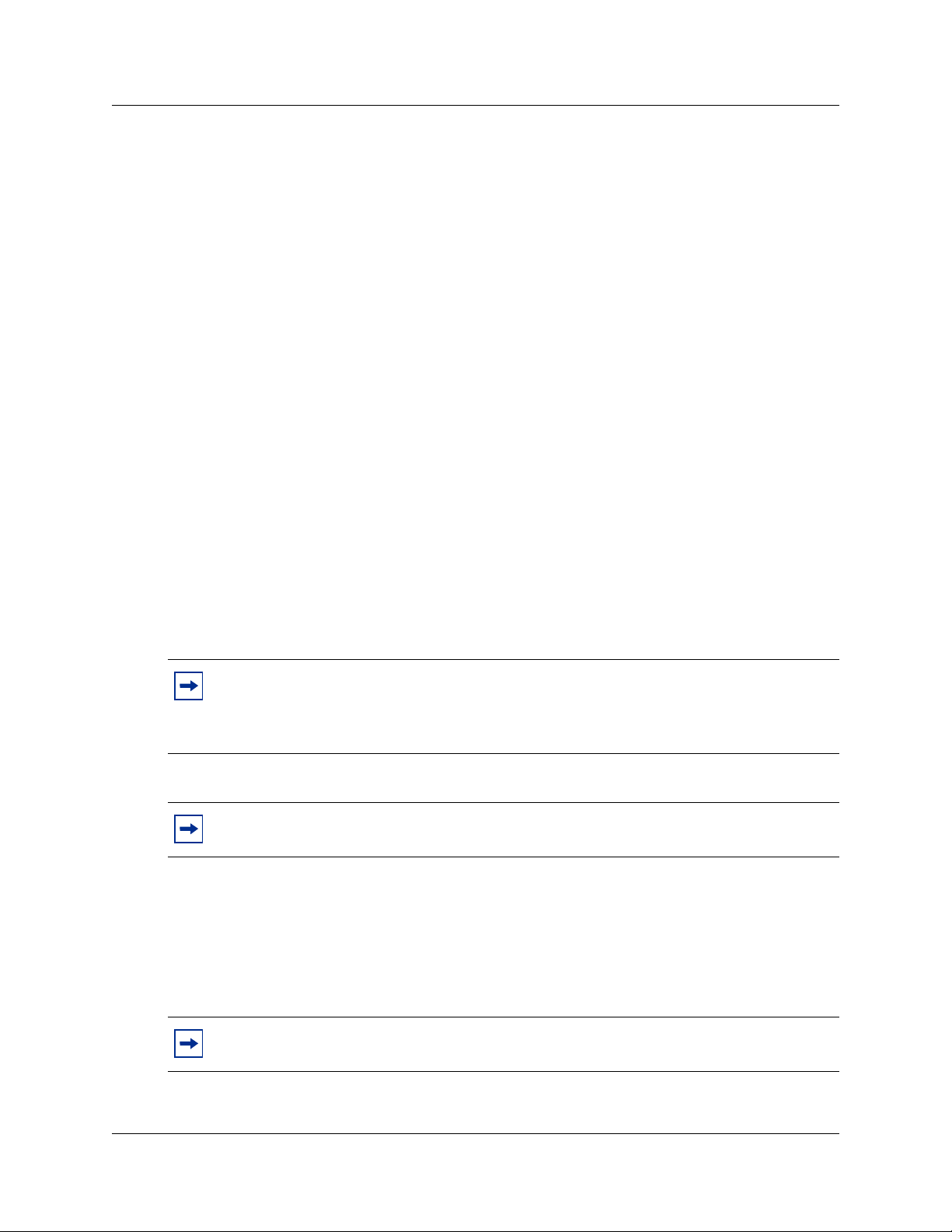
68
OAI on/off
Nortel Networks Open Application Interface (OAI) enables the wireless handset to connect with
the optional WLAN Application Gateway 2246. This device allows third-party computer
applications to display alphanumeric messages on the wireless handset display and take input from
the wireless handset keypad.
If a WLAN Application Gateway 2246 is installed in the system, OAI may be optionally enabled
in each wireless handset. Select whether the wireless handset should attempt to connect to the
WLAN Application Gateway 2246 by choosing either the Enable or Disable options in this menu.
By default, OAI is disabled.
If OAI is enabled, and a WLAN Application Gateway 2246 IP address is available to the wireless
handset (either through DHCP or Static IP configuration), then the wireless handset communicates
with the WLAN Application Gateway 2246 at power-on, and then periodically during the time the
wireless handset is powered on.
If a WLAN Application Gateway 2246 is not installed at the site, leave the OAI feature disabled to
preserve network bandwidth and battery life.
Admin PW
The optional Admin Password (PW) controls access to the administration functions in the Admin
Menu of the wireless handset. Configure the password in each wireless handset for which
controlled access is desired. Wireless handsets are shipped without an Admin password.
Note: If this option is selected on a wireless handset that already has a configured
password, and the Exit softkey is pressed with no entry, the password is erased. This
means that the wireless handset will not require an Admin Password to access the Admin
Menu.
Tip: Record the wireless handset Admin password and store it in a safe place. If the
password is lost or forgotten, contact Nortel Networks Technical Support.
Downloading the WLAN handset firmware
All WLAN Handsets 2210/2211 are shipped with a generic firmware load that allows them to
associate to a WLAN and download their functional firmware from a TFTP Server. The wireless
handsets do not function properly without downloading their appropriate firmware.
Note: It is the customer’s responsibility to download the firmware upgrades from the
Nortel Networks web site to the TFTP Server.
WLAN Handsets 2210/2211 configuration
Page 69

Pre-download checklist
The following requirements must be met to download firmware by over-the-air file transfer:
• Α wireless LAN must be properly configured and operational through the use of 802.11b
SVP-compliant wireless APs.
• Τhe Nortel Networks WLAN IP Telephony Manager 2245 must be connected to the network
and completely operational.
• Α TFTP Server must be available on the network to load the appropriate firmware into the
wireless handsets.
• The ESSID (you can get this from the AP installer).
• The IP addresses of the WLAN IP Telephony Manager 2245 and TFTP server to configure the
handsets.
• Τhe battery pack on the wireless handsets must be fully charged.
Downloading the firmware
1 Download the latest WLAN Handsets 2210/2211 firmware (.zip file) from the Nortel
Networks web site.
69
2 Extract the three firmware files from the .zip file and place them on the TFTP Server. Ensure
the TFTP Server is on before completing the following steps.
3 If statically assigning IP addresses, ensure that the wireless handset IP address, TFTP Server
IP address, Subnet Mask, and Default Gateway information are accurate in the Admin Menu
of the wireless handset. If using a DHCP Server, ensure that the DHCP options are configured.
4 Ensure the wireless handset has properly configured ESSID and Reg Domain Information
within the Admin Menu. If broadcast ESSIDs are accepted at the APs, the handset
automatically learns the ESSID information when powering on.
5 Using the Admin Menu on the wireless handset, ensure the License Management menu option
is set to 010. This ensures the handset will check for the proper UNIStim firmware files each
time it powers on.
6 Power on the wireless handset.
The firmware now downloads to the wireless handset. The status bar increments fully across
the wireless handset display for each function that is being performed in the download process.
Upon completion of the update process, the wireless handset re-boots with the new firmware.
7 Register the wireless handset with the BCM as if it were an IP Phone 2004.
8 Properly label the wireless handset with the appropriate extension number.
For future firmware upgrades, simply update the firmware files that are stored on the TFTP Server.
Each time the wireless handset is powered on, it checks with the TFTP Server to ensure it has the
proper firmware version. It downloads the new firmware, when found.
WLAN Handsets 2210/2211 configuration
Page 70

70
Programming the WLAN Handsets 2210/2211
The Line keys 1-6 on the WLAN Handsets 2210/2211 are programmable by the end user. These
Line keys can be programmed in the wireless handset in the same manner they are programmed on
the IP Phone 2004.
Follow the steps in “Programming the Line keys” to program keys on the wireless handset.
Programming the Line keys
There are three menus available for the Line keys. The menu available is dependent on the state of
the WLAN Handset 2210/2211. Two menus are programmed using the BCM and one is
user-defined. The IP features list is programmed using the BCM and is available to all handsets.
For information on user-defined programming of the Line keys and using the WLAN handset
features, refer to the Nortel Networks WLAN Handset 2210/2211 User Guide.
Configuring the idle state display
When the set is in the idle state, it displays “Ext.----”. Nortel Networks recommends that you
configure this display to show the Directory Number (DN) of the handset. To configure this
display, place the set in the idle state:
1 Press the FCN key.
2 Select Extension from the menu using the up and down arrow buttons on the left of the set.
3 Press OK.
A screen appears.
4 Enter your the DN under New Ext: on this screen.
WLAN Handsets 2210/2211 configuration
Page 71

Troubleshooting
This section describes options for troubleshooting your WLAN system and its devices. For site
and deployment information, refer to “Appendix D: Provisioning” on page 113.
Troubleshooting the WLAN IP Telephony Manager 2245
Options on the System Status Menu screen provide a window into the real-time operation of the
components of the system. Use this data to evaluate system function and to troubleshoot areas that
may be experiencing problems.
The System Status Menu screen is shown in Figure 11.
Figure 11 System Status Menu screen
71
The following options can be selected:
• Error Status – displays alarm and error message information.
• Network Status – displays information about the Ethernet network to which the WLAN IP
Telephony Manager 2245 is connected.
• Software Versions – lists the software versions for the WLAN IP Telephony Manager 2245.
Error Status screen
The Error Status screen displays any alarms that indicate a system malfunction. Some of these
alarms are easily remedied. Others require a call to Nortel Networks Technical Support.
Troubleshooting
Page 72

72
From the System Status Menu screen, select Error Status. The Error Status screen displays
active alarms on the WLAN IP Telephony Manager 2245. Table 7 lists the alarms and the actions
required to eliminate the alarm.
Table 7 WLAN IP Telephony Manager 2245 active alarms and actions
Alarm text Action
Maximum payload usage reached Reduce usage, clear alarm
Maximum telephone usage reached Reduce usage, clear alarm
Maximum Access Point usage reached Reduce usage, clear alarm
Maximum call usage reached Reduce usage, clear alarm
SRP audio delayed Reduce usage, clear alarm
SRP audio lost Reduce usage, clear alarm
No IP address Configure an IP address
Press C to clear all alarms that can be cleared.
Network Status screen
The WLAN IP Telephony Manager 2245 is connected to the Ethernet network (LAN). The
information about that connection is provided on the Network Status screen. The screen displays
information about the Ethernet network. This information can help troubleshoot network
problems.
To access the Network Status screen, select Network Status from the System Status Menu
screen. The Network Status screen is shown in Figure 12 on page 73.
Troubleshooting
Page 73

Figure 12 Network Status screen
73
The following information can be viewed:
• Ethernet Address – MAC address of the WLAN IP Telephony Manager 2245 (hexadecimal).
• System Uptime – the number of days, hours, and minutes since the WLAN IP Telephony
Manager 2245 was last reset.
• Net – the type of connection to the Ethernet switch currently utilized.
Displayed as 10 (10BaseT) or 100 (100BaseT)/half-duplex, full-duplex, or auto-negotiate.
• maximum calls – number of calls that can be supported by the WLAN IP Telephony Manager
2245 (depends on network speed).
• RX – Ethernet statistics about the received signal during System Uptime.
— bytes – bytes received
— packets – packets received
— errors – sum of all receive errors (long packet, short packet, CRC, overrun, alignment)
— drop – packets dropped due to insufficient memory
— fifo – overrun occurred during reception
— alignment – non-octet-aligned packets (number of bits not divisible by 8)
— multicast – packets received with a broadcast or multicast destination address
• TX – Ethernet statistics about the transmitted signal during System Uptime.
— bytes – bytes transmitted
— packets – packets transmitted
— errors – sum of all transmit errors (heartbeat, late collision, repeated collision, underrun,
carrier)
— drop – packets dropped due to insufficient memory
— fifo – underrun occurred during transmission
Troubleshooting
Page 74

74
— carrier – carrier lost during transmission
— collisions – packets deferred (delayed) due to collision
• SVP-II Access Points in Use – number of APs used by WLAN handsets, either in standby or
in a call. ‘Last’ is current, ‘Max’ is the maximum number in use at one time.
• SVP-II Access Points in Calls – number of APs with WLAN handsets in a call.
• SVP-II Telephones in Use – number of WLAN handsets in standby or in a call.
• SVP-II Telephones in Calls – number of WLAN handsets in a call.
• SVP-II SRP Audio:
— Delay – SRP audio packets whose transmission was momentarily delayed.
— Lost – SRP audio packets dropped due to insufficient memory resources.
Software Version Numbers screen
The Software Version Numbers screen provides information about the firmware version
currently running on the WLAN IP Telephony Manager 2245.
This information helps to determine if the most recent firmware version is running. This
information assists Nortel Networks Technical Support in troubleshooting firmware problems.
To access the Software Version Numbers screen, select Software Version from the System
Status Menu. The Software Version Numbers screen is shown in Figure 13.
Figure 13 Software Version Numbers screen
The Table of Contents firmware will always be 173.xxx, where xxx is the release number.
Similarly the Functional Code will always be 174.xxx and the File System will always be 175.xxx.
Troubleshooting
Page 75

Duplex mismatch
A duplex mismatch anywhere on the WLAN can cause the WLAN IP Telephony Manager 2245 to
operate improperly. Double-check WLAN connections and interfaces to ensure that they are all
configured as full-duplex.
Feature limitations
The following limitations exist for the WLAN Handsets 2210/2211:
• The WLAN Handsets 2210/2211 do not have handsfree capability. Therefore, any feature
which requires handsfree is not supported or only partially supported. For example, when
there is an incoming call to an IP Phone 2004 set that is idle, but offhook, the set buzzes the
handsfree speaker. This feature is not supported on WLAN Handsets 2210/2211.
• The WLAN Handsets 2210/2211 do not support all of the buttons present on an IP Phone
2004. The following keys are not available:
— Expand to PC key
— Navigation (Left, Right, Up, Down) Keys
—Headset Key
— Handsfree Key
—Services
75
Any operation that requires those keys is not supported.
• Any feature that requires scroll buttons is not supported. For example, Feature * 900 is not
supported on the WLAN Handsets 2210/2211. The use of Call Logs and set-based
administration is also limited due to the lack of up and down scroll buttons (for example, you
cannot erase old logs from the Call Log).
• The WLAN handsets do not have a signal strength indicator.
• The WLAN handsets do not support the Net6 feature.
• Feature F*6 affects the display, but does not change the ring tone.
• Feature F*7 does not affect the LCD display.
• The WLAN handsets can access SBA, but they cannot navigate the menus.
• The set display is 4 lines by 19 characters. Therefore, some lines may be truncated or
compressed by a special compression mechanism. Also, the softkey labels are four characters
wide instead of seven characters as on an IP Phone 2004.
• The WLAN IP Telephony Manager 2245 can block calls due to bandwidth constraints on an
AP without notifying the BCM. The caller hears ringback, and the call-forward-no answer
treatment will be applied (for example, go to voicemail).
• If the call originates from a wireless handset that is on a bandwidth-restricted AP, the caller
hears a warning tone (three “chirps”) and the call is disconnected.
Troubleshooting
Page 76

76
• If a set is mobile and moves into an AP that is already at capacity, the handset remains
associated with an AP that has sufficient bandwidth. This could result in degraded signal and
voice quality and, ultimately, a call could be dropped.
Tip: Nortel Networks recommends that you always press the End key after a call is
completed — even if the party on the other end terminates the call. If the party on the other
end terminates the call and you do not press End, the WLAN Handset 2210/2211
continues to exchange messages with the WLAN IP Telephony Manager 2245. This
consumes RF bandwidth and reduces battery life.
• End to end QoS (that is, DiffServ) is not supported. Layer 2 QoS (that is, 802.1 p/q) is not
supported. Any UNIStim commands that attempt to manipulate Layer 2 or Layer 3 QoS
parameters are ignored.
• Only G.711 and G.729 A/B codecs are supported.
• Any UNIStim messages that configure the jitter buffer are ignored.
• RTCP is not supported. Incoming RTCP packets are discarded.
• WLAN Handsets 2210/2211 do not appear in UM DN Registration > IP Wireless DN's reg'd.
Syslog Server
The WLAN IP Telephony Manager 2245 and other network devices, such as APs and handsets,
can log all error messages to a standard Syslog Server. See “Configuring the network” on page 48
for configuring the WLAN IP Telephony Manager 2245 to send error logs to the Syslog Server.
A Syslog Server listens for incoming syslog messages on UDP port 514 and then processes the
messages according to local administrative procedures. Usually the syslog messages are logged for
subsequent review by the system operator.
The Syslog Server can be any RFC 3164-compliant log server. The WLAN IP Telephony Manager
2245, WSS 2250/2270, WLAN Application Gateway 2246, WLAN APs 2220/2221, and WLAN
Access Ports 2230/2231 can be configured to generate syslog messages. For information about
configuring these devices, refer to the manufacturer’s documentation. The following websites also
contain information and documentation:
• WLAN Handsets 2210/2211 – NortelNetworks.com
• WSS 2250/2270 – NortelNetworks.com
• WLAN Access Ports 2230/2231 – NortelNetworks.com
• WLAN IP Telephony Manager 2245 – SpectraLink.com
• Other APs – refer to the specific manufacturer’s website
Troubleshooting
Page 77

Appendix A: Compatible Access Points
Introduction
Table 8 lists APs that are compatible with WLAN Handsets 2210/2211 operating on the WLAN IP
Telephony Manager 2245. 802.11b APs generally support up to 12 simultaneous calls per AP.
However, calls per AP can vary by AP manufacturer and can depend on the codec used by the host
handset. WEP encryption has been tested and is compatible with all APs listed.
Note 1: Lab Tested indicates that the AP software has been fully tested and approved.
Note 2: Field Verified indicates that the AP software has been verified in field installations.
Table 8 SVP-compliant APs (Sheet 1 of 2)
77
Lab
Manufacturer Make/Model Radio Technology Software Version
Airespace Wireless Enterprise Platform 802.11b 1.2.59 √√
Alvarion BreezeNET Pro. 11 Series
Avaya Wireless Access Point AP-1,
Avaya Wireless Access Point AP-3 802.11b 2.2.4 or later √
Avaya Wireless Access Point AP-4,
Cisco Aironet 3500 802.11-FH 8.12 or later √√
Cisco Aironet 4500 802.11b 8.12 or later √√
Cisco Aironet 4800 802.11b 8.24 or later √√
Cisco Aironet 340 802.11b 11.10T, 12.01T1 or
Cisco Aironet 350
Cisco Aironet 1100 802.11b 12.2.13-JA1 √√
Cisco Aironet 1200 802.11b VxWorks: 12.01T1 or
Enterasys RoamAbout Access Point 2000 802.11b V6.02 √
Enterasys RoamAbout R2 802.11b V4.01.09 or later √
HP ProCurve Wireless Access Point
Intermec MobileLAN access 2100, 2101,
Intermec MobileLAN access WA21, WA22 802.11b 1.91 or later √
LXE 6520 Access Point 802.11b 3.83 or later √
AP-2
AP-6
520wl
2102
2
3
1
802.11-FH 4.4.2 or 5.0.103 √
802.11b 3.83 or later √
802.11b 2.2.4 or later √
later
802.11b VxWorks: 11.10T,
12.01T1 or later
IOS: 12.2.13-JA1
later
IOS: 12.2.13-JA1
802.11b 2.3.1 or later √
802.11b 1.91 or later √
Tested
√√
√√
√√
Field
Verified
Appendix A: Compatible Access Points
Page 78

78
Table 8 SVP-compliant APs (Sheet 2 of 2)
Lab
Manufacturer Make/Model Radio Technology Software Version
Proxim Orinoco AP-500, AP-1000 802.11b 3.83 or later √√
Proxim Orinoco AP 600b 802.11b 2.3.1 or later √
Proxim Orinoco AP-2000 802.11b 2.3.1 or later √
Symbol Spectrum 24 FH 802.11-FH 4.02-12 √√
Symbol Spectrum 24 DS (4131) 802.11b 3.50-18 √
Symbol Wireless Switch System
(WS5000 & AP100)
Teklogix 9150 Wireless Gateway 802.11b K112p or later √
Telxon Air-I/O 802FH UAP 802.11-FH 8.24 √√
Telxon Air-I/O 802DS UAP,
1
Alvarion BreezeNET Pro.11 Series software version 4.4.5 is not compatible with the
Air-I/O 802DS 11 UAP
802.11b 1.1.4.30SP1 √
802.11b 8.12 or 8.24 √√
Tested
Field
Verified
WLAN IP Handsets 2210/2211.
2
Cisco Aironet 350 software version 11.21 is not compatible with the
WLAN IP Handsets 2210/2211.
3
For detailed setup instructions for the HP Procurve Wireless Access Point 520wl, use the Proxim
AP 2000 Configuration Note.
Appendix A: Compatible Access Points
Page 79

Appendix B: WLAN Application Gateway 2246
WLAN Application Gateway 2246
The WLAN Application Gateway 2246 is an optional device that enables third-party applications
to communicate directly with up to 10 000 WLAN handsets. The WLAN Application Gateway
2246 is connected to the LAN Ethernet switch through an RJ-45/CAT5 cable.
The Application Server is connected through the RS-232 port or through the Ethernet connection.
The client’s system can include a LAN and its Application Server with a TAP connection to a
communications device such as a paging controller.
A WLAN Application Gateway 2246 supports 64 to 10 000 wireless handsets, depending on the
model of Gateway, as listed in Table 9.
Table 9 Model numbers with maximum number of users
Maximum
Model number
number of users
79
MOG600 64
MOG710 128
MOG720 256
MOG730 512
MOG740 1024
MOG750 10000
The optional WLAN Application Gateway 2246 requires a 10 Mbit/s half-duplex switched
Ethernet connection.
Physical description
There are two different WLAN Application Gateway 2246 models with similar front panel
indicators. Refer to Figure 14 on page 80 and Figure 15 on page 80.
The MOG6xx model supports up to 64 users.
Appendix B: WLAN Application Gateway 2246
Page 80

80
Figure 14 Model MOG6xx
The power jack and network port are located on the back of the Model MOG6xx.
The MOG7xx model is available in scaled increments to support up to 10 000 users.
Figure 15 MOG7xx
The two types of LEDs on the front panels of both the MOG6xx model and the MOG7xx model
are the following:
• Network Link LEDs
— (L)NKOK: lit when there is a network connection (for example, LINK OK)
— (A)CT: lit if there is system activity
— (C)OL: lit if there are network collisions
— (E)RROR: lit when the system has detected an error
• Status LEDs that indicate system messages and status.
— 1: heartbeat, indicates the WLAN Application Gateway 2246 is running
— 2, 3, and 4: currently unused
— 5: System master
Installation
This section explains how to install the WLAN Application Gateway 2246.
Appendix B: WLAN Application Gateway 2246
Page 81

81
For an overview of the WLAN Application Gateway 2246, refer to “WLAN Application Gateway
2246” on page 79.
For information on configuring the WLAN Application Gateway 2246, refer to “Configuration”
on page 86.
Tasks:
• Prepare to install the WLAN Application Gateway 2246 (“Preparing to install the WLAN
Application Gateway 2246” on page 81)
• Mounting the WLAN Application Gateway 2246 (“Mounting the WLAN Application Gateway
2246” on page 82)
• Connect to the Local Area Network (LAN) (“Connecting to the LAN” on page 82)
• Connect the power (“Connecting the power” on page 83)
• Connect to the Application Server (“Connecting to the Application Server” on page 83)
If the WLAN Application Gateway 2246 is being added to an existing system, the entire system
must be reset before the WLAN Application Gateway 2246 can be used.
Preparing to install the WLAN Application Gateway 2246
Required Materials
Each WLAN Application Gateway 2246 is shipped with one Class II AC adapter with 24V DC,
1A output.
The following equipment must be provided by the customer:
• 10BaseT CAT5 cable with an RJ-45 connector for the optional WLAN Application Gateway
2246 – provides a connection to the Ethernet switch.
• DB-9 female null-modem cable – required for initial configuration of the WLAN IP
Telephony Manager 2245 and WLAN Application Gateway 2246.
Pre-installation checklist
Locate the WLAN Application Gateway 2246 in a space with:
• sufficient backboard mounting space and proximity to the LAN access device (switched
Ethernet switch), Call Server, and power source
• rack-mount unit (if using)
• easy access to the front panel, which is used for cabling
Appendix B: WLAN Application Gateway 2246
Page 82

82
• for the WLAN Application Gateway 2246, a maximum distance of 325 feet (100 meters) from
the Ethernet switch
Mounting the WLAN Application Gateway 2246
The WLAN Application Gateway 2246 is physically connected to the Ethernet switch and can be
placed in any convenient location within 325 feet (100 m) of the switch.
The WLAN Application Gateway 2246 can be mounted either vertically or horizontally.
The rack-mount kit is designed for mounting the WLAN Application Gateway 2246 in a standard
19-inch rack and contains the following equipment:
• Mounting plates – two for each WLAN Application Gateway 2246 to be mounted.
• Screws – four rack-mount screws for each WLAN Application Gateway 2246 to be mounted.
Wall-mounting the WLAN Application Gateway 2246
1 Use a 1/8-inch drill bit to drill four pilot holes, on 1.84-by-12.1 inch centers (approximately
equivalent to 1-13/16 inch by 12-1/8 inch).
2 Insert the #8 x 3/4-inch screws in the pilot holes and tighten, leaving a
1/8 to 1/4-inch gap from the wall.
3 Slide the WLAN Application Gateway 2246 over the screws until it drops into place in the
keyhole openings of the flange.
4 Tighten screws fully.
Rack-mounting the WLAN Application Gateway 2246
1 Remove the corner screws from the WLAN Application Gateway 2246.
2 Screw the U-shaped end (round screw holes) of the two mounting plates to the WLAN
Application Gateway 2246.
3 Screw the other end of the two mounting plates (oblong screw holes) to the rack.
4 Repeat steps 1-3 for each additional WLAN Application Gateway 2246. The mounting plate is
designed to provide the correct minimum spacing between units. When mounting multiple
units, stack the units in the rack as closely as possible.
Connecting to the LAN
Use an RJ-45 cable to connect the NETWORK port on the WLAN Application Gateway 2246 to
the connecting port on the Ethernet switch.
Appendix B: WLAN Application Gateway 2246
Page 83

Connecting the power
1 Connect the power plug from the AC adapter to the power jack on the front (or rear) of the
WLAN Application Gateway 2246.
Warning: Use only the provided Class II AC adapter with output 24V DC, 1A.
2 Plug the AC adapter into a 110V AC outlet to supply power to the WLAN Application
Gateway 2246.
The system cycles through diagnostic testing and the LEDs blink for approximately one
minute.
3 Apply power to the WLAN Application Gateway 2246. When the system is ready for use,
verify the following:
•The ERROR LED is off.
• LED 1 is blinking.
83
Connecting to the Application Server
The WLAN Application Gateway 2246 is connected to the site’s LAN through an Ethernet switch.
The connection to the Application Server can be accomplished by a direct connection (RS-232) or
through the Ethernet connection. Only one of these connections can be used at one time.
The IP address of the WLAN Application Gateway 2246 must be set during configuration. Once
the IP address is established, the WLAN Application Gateway 2246 can be accessed by the
Application Server through the RS-232 port or the through the LAN using Telnet.
Some applications require a LAN connection between the Application Server and the WLAN
Application Gateway 2246. There are three methods to achieve this connection:
• Connecting through the LAN – If the applications have the ability to communicate messages
over TCP/IP, and do not require a serial connection.
• Connecting through an RS-232 port – if a LAN connection is not required or not possible.
Some applications or systems may require an RS-232 connection between the Application
Server and the WLAN Application Gateway 2246.
• Connecting through a modem – In some situations, a modem is used for remote
administration.
Connecting through the LAN
The IP address must be configured for the WLAN Application Gateway 2246 to function on the
LAN. Follow the application’s instructions to identify the WLAN Application Gateway 2246 to
the application. See Figure 16 on page 84.
Appendix B: WLAN Application Gateway 2246
Page 84

84
r
r
p
p
Figure 16 WLAN Application Gateway 2246 connection through the LAN
LAN
Ethernet
switch
WLAN Application
Gateway 2246
Application
Serve
(PC)
Connecting through an RS-232 port
Connect the Application Server to the WLAN Application Gateway 2246 serial port by using a
cable that conforms to RS-232 standards for DTE-to-DTE connections (null modem cable). See
Figure 17.
Figure 17 RS-232 cable connection
LAN
Ethernet
switch
RS-232
ort
WLAN Application
Gateway 2246
RS-232
ort
Application
Serve
(PC)
The WLAN Application Gateway 2246 uses the pins listed in Table 10 on the connector.
Table 10 Pins on the connector
Pin Function
1 Carrier Detect
2 Data OAI Receives
3 Data OAI Transmits
5 Ground
7 Ready to Send
8 Clear to Send
Appendix B: WLAN Application Gateway 2246
Page 85

Connect through a modem
p
Connect the modem to the WLAN Application Gateway serial port using a cable that conforms to
RS-232 standards for DTE-to-DCE connections. See Figure 18.
Figure 18 WLAN Application Gateway 2246 connection through a modem
85
LAN
Ethernet
switch
RS-232
WLAN Application
Gateway 2246
modem
DCE
Dedicated
DTE
ort
Appendix B: WLAN Application Gateway 2246
Page 86

86
Configuration
This section explains how to configure the WLAN Application Gateway 2246.
For an overview of the WLAN Application Gateway 2246, refer to “WLAN Application Gateway
2246” on page 79.
For information on installing the WLAN IP Telephony Manager 2245, refer to “Installation” on
page 80.
Tasks:
• Connect to the WLAN IP Telephony Manager 2245 (“Connecting to the WLAN Application
Gateway 2246” on page 86)
• Configure the WLAN IP Telephony Manager 2245 (“Configuring the WLAN Application
Gateway 2246” on page 88)
• Change the password (“Connecting to the WLAN Application Gateway 2246” on page 86)
• Save the configuration (“Connecting to the WLAN Application Gateway 2246” on page 86)
• Check system status (“Connecting to the WLAN Application Gateway 2246” on page 86)
Connecting to the WLAN Application Gateway 2246
The initial connection to the WLAN Application Gateway 2246 must be made through a serial
connection to establish the IP address of the WLAN Application Gateway 2246 and the network
parameters.
Further configuration and administration can be performed at a later time through a Telnet
connection.
The Telnet method of connection is also used for routine maintenance of the WLAN Application
Gateway 2246.
Tips: Nortel Networks recommends that you complete the initial network configuration
through the serial connection.
You should also change the default password immediately for security reasons (see
“Connecting to the WLAN Application Gateway 2246” on page 86).
Appendix B: WLAN Application Gateway 2246
Page 87

Connecting through a serial port
p
1 Connect the WLAN Application Gateway 2246 to the serial port of a terminal or PC using a
DB-9 female, null-modem cable. See Figure 19.
Figure 19 Cable to port connection
LAN
Ethernet
switch
RS-232
WLAN Application
Gateway 2246
port
RS-232
ort
Terminal or PC
87
2 Run a terminal emulation program (such as HyperTerminal™), or use a VT-100 terminal with
the following configuration:
— Bits per second: 9600
— Data bits: 8
— Parity: None
— Stop bits: 1
— Flow control: None
Note: If using Windows 2000, Service Pack 2 must be installed to enable the use of
HyperTerminal™.
3 Reset the system.
The following appears on the terminal:
04830130
4 Type the following command using the terminal or PC keyboard:
0255CC [CTRL M] [CTRL J]
The command does not display on the screen as it is typed.
The login screen appears. If an error was made when entering the command string, the
message “Ill Formed Packet” appears. It appears as a series of numbers followed by some
form of the typed command. If this occurs, repeat Step 3 and Step 4.
Appendix B: WLAN Application Gateway 2246
Page 88

88
5 Enter the default login name (admin) and the default password (admin).
Note: The login name and password are case-sensitive.
The NetLink OAI System menu appears. See Figure 20 on page 88.
Figure 20 NetLink OAI System menu
The NetLink OAI System menu of the Administration Console displays the factory-default
name of the WLAN Application Gateway 2246 to which the serial port is connected.
Note: If the WLAN Application Gateway 2246 is a MOG6xx model, the TFTP Server
Download Configuration option appears on the NetLink OAI System menu.
Configuring the WLAN Application Gateway 2246
The NetLink OAI System menu is the main menu of the Administration Console. Use this screen
to configure the WLAN Application Gateway 2246.
Appendix B: WLAN Application Gateway 2246
Page 89

Configuring the OAI Box
1 Select OAI Box Configuration from the NetLink OAI System menu.
The OAI Box Configuration screen appears (see Figure 21 on page 89).
Figure 21 OAI Box Configuration screen
89
Note 1: ** – Option appears only on the MOG6xx model.
Note 2: * – This option does not appear unless “Use NetLink GW with mogX00” is set to
“Yes”, as it is in this screen, which is the default.
2 Configure the following fields with information provided by the network administrator:
• Use NetLink GW with mogX00 – change this option to No.
• TFTP Download Master – enter the IP address of the TFTP Server.
• Maintenance Lock – the system sets this option to Ye s after maintenance activities have
been performed that require a reset. This option cannot be changed. It is automatically set.
Reset the system at exit to clear Maintenance Lock. Maintenance Lock prevents any new
calls from starting.
• Reset System – if this option is set to Ye s, the WLAN Application Gateway 2246 is reset
after pressing ENTER.
• Reset All Systems – not applicable.
3 Press Esc on the keyboard to return to the NetLink OAI System menu.
Appendix B: WLAN Application Gateway 2246
Page 90
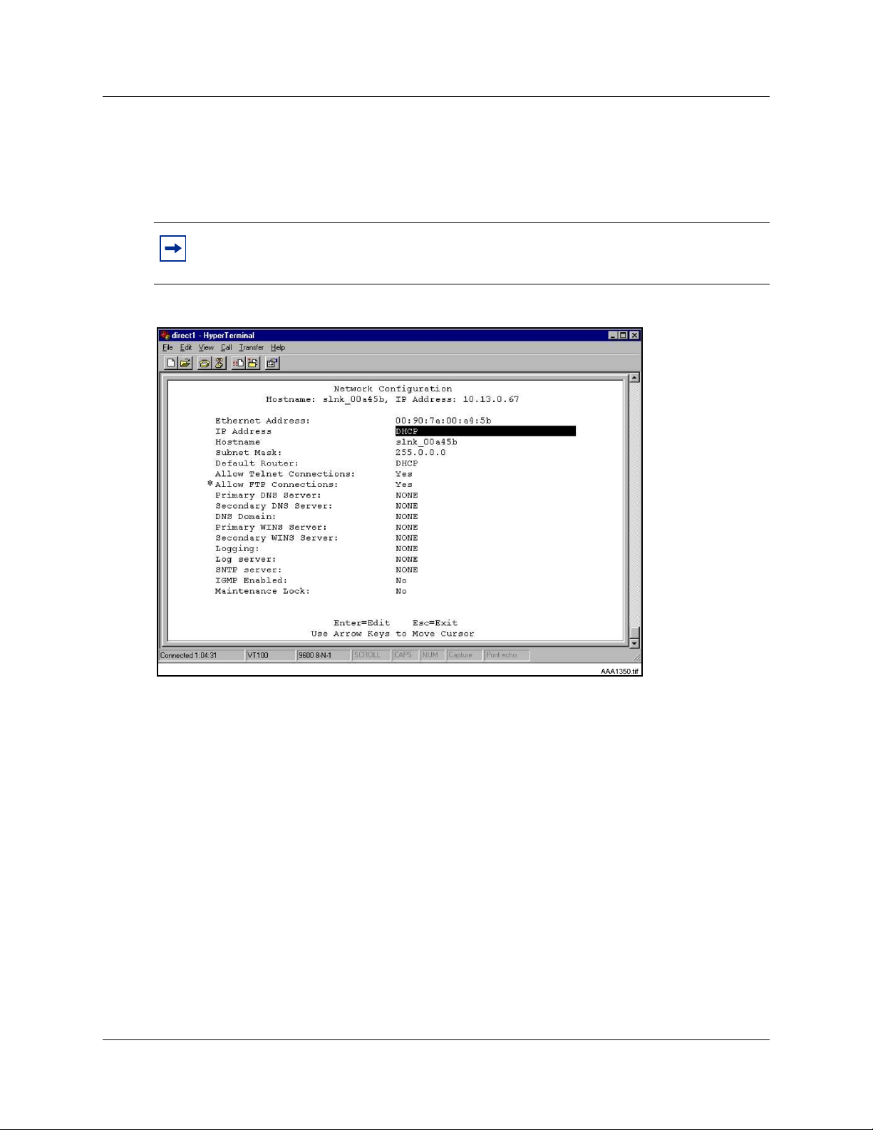
90
Configuring the network
1 Select Network Configuration from the NetLink OAI System menu.
The Network Configuration screen appears (see Figure 22).
Note: * - The Allow FTP Connections option appears only for MOG7xx models.
Figure 22 Network Configuration screen
2 Configure the following fields with information provided by the network administrator:
• Ethernet Address – this is the MAC address of the WLAN Application Gateway 2246.
This address is set at the factory.
• IP Address – enter the complete IP address for the WLAN Application Gateway 2246,
including digits and periods. Do not use DHCP. The IP address can be changed after initial
configuration.
• Hostname – the default host name can be changed. This is the name of the WLAN
Application Gateway 2246 to which connection has been made. This name is for
identification purposes only. Spaces cannot be entered in this field.
• Subnet Mask – Enter the subnet mask defined by the network administrator.
• Default Router – DHCP or static IP address.
• Allow Telnet Connections – Enter Y (Yes) to allow connection to the WLAN Application
Gateway 2246 through Telnet. Enter N (No) if no Telnet connection is allowed.
• Allow FTP Connections – Yes/No (MOG 7xx only).
Appendix B: WLAN Application Gateway 2246
Page 91

91
• DNS server and DNS domain – these settings are used to configure DNSs. (These
settings can also be configured as DHCP. This causes the DHCP client in the WLAN
Application Gateway 2246 to attempt to automatically obtain the correct configuration
from the DHCP server. The DHCP setting is only valid when the IP address is also
acquired using DHCP).
• WINS servers – these settings are used for Windows Internet Name Services (WINS).
(These settings can also be configured as DHCP. This causes the DHCP client in the
WLAN Application Gateway 2246 to attempt to automatically obtain the correct setting
from the DHCP server. The DHCP setting is only valid when the IP address is also
acquired using DHCP. When WINS is configured properly, the WLAN Application
Gateway 2246 can translate hostnames to IP addresses. When using Telnet, it is also
possible to access the WLAN Application Gateway 2246 using its hostname instead of the
IP address.
• Logging – Logging can be set to Syslog or NONE.
• Log server – enter the IP address or hostname of the Syslog server on the network if
Syslog has been configured. The WLAN Application Gateway 2246 writes Syslog format
diagnostic messages to the Syslog server.
• SNTP server – can be configured as a hostname, IP address, or NONE. The SNTP server
is a Simple Network Time server. The WLAN Application Gateway 2246 obtains the
current date and time from the SNTP server and tags syslog messages with the date.
• IGMP Enabled – configure as Ye s or No. IGMP is Internet Group Routing Protocol.
IGMP Enabled allows the WLAN Application Gateway 2246 to join multicast groups.
Enable this option if the network switch connected to the WLAN Application Gateway
2246 requires IGMP for multicast traffic to be forwarded.
• Maintenance Lock – the system sets this option to Ye s after maintenance activities have
been performed that require a reset. This option cannot be changed. It is automatically set.
Reset the system at exit to clear Maintenance Lock. Maintenance Lock prevents any new
calls from starting.
3 Press ESC to return to the NetLink OAI System menu.
4 Reset the WLAN Application Gateway 2246.
Continuing configuration through Telnet
Once the IP address for the WLAN Application Gateway 2246 has been configured and reset, and
the WLAN Application Gateway 2246 has been connected to the LAN and the Application Server,
Telnet can be used to continue the configuration of the WLAN Application Gateway 2246.
Connecting through Telnet
Connection to the WLAN Application Gateway 2246 can be done through the network using
Telnet. Telnet can only be used after the IP address of the WLAN Application Gateway 2246 has
been configured.
Appendix B: WLAN Application Gateway 2246
Page 92

92
The Telnet method of connection is used for routine maintenance of the system for both local and
remote administration, depending on the network.
Follow the steps to connect to a WLAN Application Gateway 2246 through Telnet.
Connecting to a WLAN Application Gateway 2246 through Telnet:
1 Run a Telnet session to the IP address of the WLAN Application Gateway 2246.
2 Log in to the WLAN Application Gateway 2246.
The NetLink OAI System screen appears.
Note: Since the WLAN Application Gateway 2246 has been initially configured, the NetLink
OAI System screen now has some different options displayed.
When the configuration procedure is complete, the NetLink OAI System screen adds a Feature
Programming option. Also, the OAI Line Configuration option is replaced by a Telephone Line
Configuration option. See Figure 23.
Figure 23 NetLink OAI System screen with added options
Appendix B: WLAN Application Gateway 2246
Page 93

93
Configuring the Telephone Line
Each WLAN Handset 2210/2211 that uses the application’s features must be configured with its
line number and MAC address. The name and extension number of the WLAN Handset 2210/
2211 user can be entered. Obtain this information from the WLAN Handset 2210/2211 Planning
Worksheet. See Planning Worksheet for WLAN Handsets 2210/2211 on page 106.
The WLAN Handsets 2210/2211 require special configuration. This can include configuring
options on the DHCP server or on the WLAN Handset 2210/2211 to allow it to communicate with
the WLAN Application Gateway 2246. Be sure these setting are correct. Refer to Configuring the
WLAN Handsets 2210/2211 on page 60 for more information.
The system does not allow the same WLAN Handset 2210/2211 to register to two different lines.
Use Esc to cancel any unwanted transaction.
Follow the steps to configure the telephone lines for the application.
Configuring a telephone line:
1 From the NetLink OAI System screen, select Telephone Line Configuration and press
Enter.
The Telephone Line Configuration screen appears. See Figure 24.
Figure 24 Telephone Line configuration
2 Use the arrow keys to navigate to the Name and Extension fields.
3 Enter the associated data for the wireless handsets.
Appendix B: WLAN Application Gateway 2246
Page 94

94
• MAC Address – the MAC address is printed on the sticker underneath the battery
on the WLAN Handsets 2210/2211. It can also be displayed on the WLAN Handsets
2210/2211 by turning off the wireless handset, and then pressing and holding the
Pwr (power) button. The MAC address appears on the first line of the wireless
handset display (12 characters). The MAC address must be manually entered by
typing the entire address, including digits and colons.
• Name – enter the user name assigned to the wireless handset. This is for record
keeping only; it does not communicate the name to the Call Server or the WLAN
Handsets 2210/2211.
• Extension – enter the extension number assigned to the WLAN Handset 2210 or
2211. This is for record keeping only; it does not communicate the extension number
to the Call Server or the WLAN Handsets 2210/2211.
4 Write the MAC address on the Wireless Handset Planning Worksheet. See Planning
Worksheet for WLAN Handsets 2210/2211 on page 106.
5 Repeat Step 2, Step 3, and Step 4 for each wireless handset to be added or changed.
6 Press Esc to return to the NetLink OAI System screen.
Deleting a WLAN Handset 2210 or 2211
Follow the steps to delete a WLAN IP Telephony Manager.
Perform the following steps to delete a WLAN Handset 2210/2211.
1 From the NetLink OAI System screen, select Telephone Line Configuration and press
Enter.
The Telephone Line Configuration screen appears.
2 Use the arrow keys to highlight the line to be deleted.
3 Press D to delete the WLAN Handset 2210 or 2211 information.
4 Press Y to accept changes.
5 Press Esc to return to the NetLink OAI System screen.
Searching for a WLAN Handset 2210/2211
While in the Telephone Line Configuration or the Telephone Line Status screens, a search hotkey
is available.
Follow the steps to search for a WLAN Handset 2210/2211.
Searching for a WLAN Handset 2210/2211:
Appendix B: WLAN Application Gateway 2246
Page 95

1 From the NetLink OAI System screen, select Telephone Line Configuration and press
Enter.
The Telephone Line Configuration screen appears.
2 Select the field to use as the search key (MAC Address, Name, or Extension),
3 Press S to display a search screen dialog box.
4 Type an appropriate search string.
5 Press Enter.
The success or failure of the search is displayed at the bottom of the screen.
6 Continue to change the search string for different search criteria or exit by pressing the Esc
key.
The first line of the Telephone Line Configuration or Telephone Line Status screen displays the
line in which the search match is found.
Successful searches always have the first found match at the top of the list.
Note: Partial strings match for beginnings of strings, (for example, a search for extension
10 matches extensions 10, 100, 1000, and so on, but will not match 010).
95
Programming a feature
The application function is accessed in the WLAN Handset 2210/2211 by pressing the FCN button
plus a second button. The button used to access the application feature from the wireless handset is
configured through the Feature Programming option.
Note: FCN 1-6 are hard-coded. If the application function is programmed to use FCN 1-6, the
hard-coded function is overridden. Nortel Networks recommends using 7, 8, or 9 for the
application function.
Follow the steps to program an application feature for the wireless handsets.
Perform the following steps to program a feature.
1 From the NetLink OAI System screen, select Feature Programming and press Enter.
The Feature Programming screen appears. See Figure 25 on page 96.
Appendix B: WLAN Application Gateway 2246
Page 96

96
Figure 25 Feature programming screen
2 Use the arrow keys to select the function number 7, 8, or 9 to associate with the application.
3 Type any label up to six characters.
What is typed here is displayed on the WLAN Handset 2210/2211 telephone display screen
next to the assigned number on the FCN menu.
In Figure 25, the FCN + # key sequence displays PhonBk on the WLAN Handset 2210/2211
function menu. Figure 25 shows an application; in this case, a phone book enabling speed dialing
to those listed.
Setting or changing a password
A unique password can be configured for the WLAN Application Gateway 2246. The password
restricts access to the device’s administrative functions.
Tip: Record the password and store it in a safe place. If the password is lost or forgotten,
contact Nortel Networks Technical support.
Follow the steps to configure or change a password on the WLAN Application Gateway 2246.
Setting or changing a password:
1 From the NetLink OAI System screen, select Change Password and press Enter.
The Change Password screen appears. See Figure 26 on page 97.
Appendix B: WLAN Application Gateway 2246
Page 97

Figure 26 Change password
97
Note: * - not applicable.
2 Use the default password admin.
3 Follow the prompts to configure a new password.
Viewing system status
To view the status of the system, select the System Status Menu option from the NetLink OAI
System screen. The Systems Status Menu screen appears
. See Figure 27 on page 98.
Appendix B: WLAN Application Gateway 2246
Page 98

98
Figure 27 System Status Menu screen
The following options can be selected:
• Application Active – displays Ye s when the application is communicating correctly with the
WLAN Application Gateway 2246. Displays No when the application is not connected. This
field is read-only and changes dynamically.
• Error Status –The only application-specific error is No ECP heartbeat, which means the
application failed to send a heartbeat to the WLAN Application Gateway 2246.
• Network Status – information about the connection to the LAN. Refer to Viewing network
status on page 98.
• Software Versions – lists the software versions currently running on the WLAN Application
Gateway 2246. Refer to Viewing software versions on page 101.
• * Telephone Line Status – information about the functioning of each wireless handset
registered to the WLAN Application Gateway 2246. Refer to Viewing Telephone Line Status
on page 100.
Viewing network status
The WLAN Application Gateway 2246 is connected to the Ethernet network, referred to as the
LAN. The information about this connection displayed on the Network Status screen.
From the System Status Menu screen, select Network Status. The Network Status screen
displays information about the Ethernet network. This information can help troubleshoot network
problems. See Figure 28 on page 99.
Appendix B: WLAN Application Gateway 2246
Page 99

Figure 28 Network Status
99
The following information is displayed at the top of the screen:
• Ethernet Address – MAC address of the WLAN Application Gateway 2246 (hexadecimal).
• Stats Time Period – the length of time the statistics have been accumulating in the Pkts and
Bytes columns. This is either the system uptime, or the time that has elapsed since a user
pressed C=Clear while viewing this display.
• User Time Period – the length of time (in seconds) that statistics accumulate in the Userpkts
column before resetting to zero. When troubleshooting a problem, use this setting to isolate
statistics for a given time period (for example, one hour). This is the only field in this screen
that can be changed by the user.
The rest of the display is a table of Ethernet statistics. The Pkts and User Pkts columns list the
count of Ethernet packets received or transmitted. The Bytes column is the count of bytes received
or transmitted during the amount of time indicated by the Stats Time Period.
• RX – number of packets and bytes received addressed to the WLAN Application Gateway
2246.
• RX Broadcast – the number of broadcast packets and bytes received.
• RX Multicast – the number of packets and bytes received with the multicast address. (A
“multicast” message is sent to more than one destination on the network.)
• RX Not For Us – the number of multicast packets and bytes received that were not for the
WLAN Application Gateway 2246.
• TX – the total number of packets and bytes transmitted.
• Interrupts – the number of times the Ethernet controller signals the microprocessor that it has
received or sent a packet.
Appendix B: WLAN Application Gateway 2246
Page 100
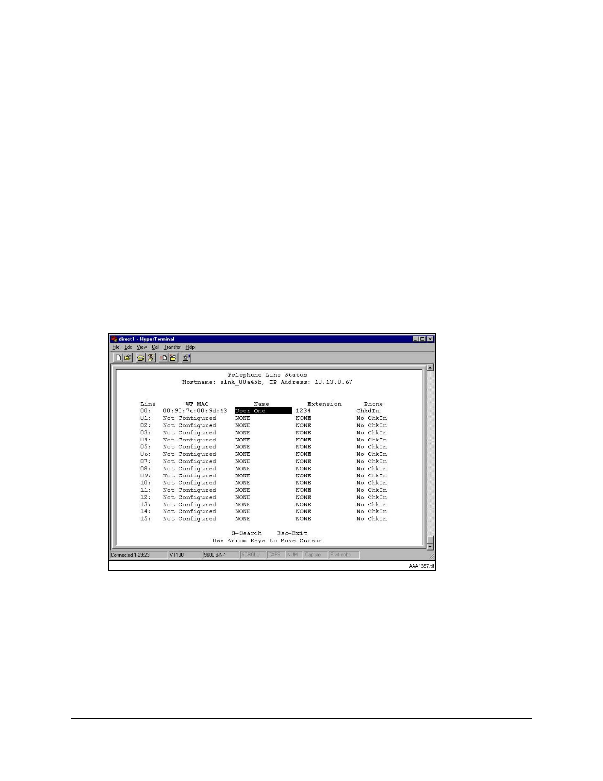
100
• Collisions – the number of times the Ethernet controller attempts to send a packet, but another
device on the network transmitted at the same time, corrupting the transmission.
• Collision Drops – the number of packets the Ethernet controller discards, because there were
over sixteen collisions. After sixteen collisions, the Ethernet controller hardware discards the
current packet and attempts to send the next packet in its buffer.
• CRC Errors – the number of packets discarded by the Ethernet controller, because of a Cyclic
Redundancy Check (CRC) error.
Viewing Telephone Line Status
The Telephone Line Status screen shows which wireless handsets are communicating with the
WLAN Application Gateway 2246.
From the System Status Menu screen, select Telephone Line Status. The WLAN Application
Gateway 2246 displays up to 16 telephone lines at one time. See Figure 29. Move to the next
group of 16 lines by using the arrow keys.
Figure 29 Telephone Line Status screen
The following information is displayed on the Telephone Line Status screen:
• WT MAC – the MAC address of the WLAN Handset 2210/2211 that was entered when the
wireless handset was configured.
• Name/Extension – these fields contain the data entered at configuration.
• Phone – No ChkIn indicates the WLAN Handset 2210/2211 is not using the application
function. ChkIn indicates the WLAN Handset 2210/2211 is communicating with the WLAN
Application Gateway 2246.
Appendix B: WLAN Application Gateway 2246
 Loading...