

Page 1

NTDE04AB
555-8421-211
Digital Telephone IP Adapter
Installation and Administration Guide
Product release 1.5 Standard 2.1 January 2005
Page 2

Page 3

Digital Telephone IP Adapter
Installation and Administration Guide
Product release: 1.5
Publication number: 555-8421-211
Document release: Standard 2.1
Date: January 2005
Copyright © 2005 Nortel. All Rights Reserved.
Printed in Canada.
All information contained in this document is subject to change without notice. Nortel reserves the
right to make changes to equipment design or program components, as progress in engineering,
manufacturing methods, or other circumstances may warrant.
*Nortel, the Nortel logo, the Globemark, and Unified Networks, Meridian 1 PBX, Communication
Server 1000S (CS 1000S), and Communication Server 2100 (CS 2100) are trademarks of Nortel.
TelStrat is a registered trademark of TelStrat International, Ltd. Microsoft, MS-DOS, and Windows
are trademarks of Microsoft Corporation.
Page 4

Page 5

Publication history
January 2005
July 2004
October 2001
September 2001
This is the Standard 2.1 issue of the Digital Telephone IP
Adapter Installation and Administration Guide (NTP 555-
8421-211). This document provides product descriptions,
planning, installation, configuration, administration, and
troubleshooting information for product release 1.5 of the
Digital Telephone IP Adapter unit.
This is the Standard 2.0 issue of the Digital Telephone IP
Adapter Installation and Administration Guide (NTP 5558421-211). This document provides product descriptions,
planning, installation, configuration, administration, and
troubleshooting information for product release 1.5 of the
Digital Telephone IP Adapter unit.
This is the Standard 1.1 issue of the Digital Telephone IP
Adapter Installation and Administration Guide (NTP 5558421-211). This document provides product descriptions,
planning, installation, configuration, administration, and
troubleshooting information for the product release 1.3 of the
Digital Telephone IP Adapter unit.
This is the Standard 1.0 issue of the Digital Telephone IP
Adapter Installation and Administration Guide (NTP 5558421-211). This document provides product descriptions,
planning, installation, configuration, administration, and
troubleshooting information for product release 1.3.0 of the
Digital Telephone IP Adapter unit.
Page 6

Publication history Standard 2.1
vi Digital Telephone IP Adapter Installation and Administration Guide
Page 7

Contents
About this document xv
About this guide . . . . . . . . . . . . . . . . . . . . . . . . . . . . . . . . . . . . . . . . . . . . . . . xvi
Product overview . . . . . . . . . . . . . . . . . . . . . . . . . . . . . . . . . . . . . . . . . . . . . xvii
Skills you need . . . . . . . . . . . . . . . . . . . . . . . . . . . . . . . . . . . . . . . . . . . . . . .xviii
Conventions used in this guide. . . . . . . . . . . . . . . . . . . . . . . . . . . . . . . . . . . . xx
Related information products . . . . . . . . . . . . . . . . . . . . . . . . . . . . . . . . . . . . xxii
1 Digital Telephone IP Adapter description 25
Product Introduction . . . . . . . . . . . . . . . . . . . . . . . . . . . . . . . . . . . . . . . . . . . . 26
Hardware description . . . . . . . . . . . . . . . . . . . . . . . . . . . . . . . . . . . . . . . . . . . 29
How to use this guide. . . . . . . . . . . . . . . . . . . . . . . . . . . . . . . . . . . . . . xvi
Nortel product knowledge . . . . . . . . . . . . . . . . . . . . . . . . . . . . . . . . . xviii
Telecommunications knowledge. . . . . . . . . . . . . . . . . . . . . . . . . . . . . xviii
Data networking knowledge. . . . . . . . . . . . . . . . . . . . . . . . . . . . . . . . . xix
Precautionary messages. . . . . . . . . . . . . . . . . . . . . . . . . . . . . . . . . . . . xx
Instructions for selecting menu options . . . . . . . . . . . . . . . . . . . . . . . . xx
Instructions for displaying property sheets . . . . . . . . . . . . . . . . . . . . . xx
PBX terminology . . . . . . . . . . . . . . . . . . . . . . . . . . . . . . . . . . . . . . . . . xxi
Printed documents . . . . . . . . . . . . . . . . . . . . . . . . . . . . . . . . . . . . . . . xxii
CD-ROM . . . . . . . . . . . . . . . . . . . . . . . . . . . . . . . . . . . . . . . . . . . . . . xxiii
Digital Telephone Internal IP Adapter . . . . . . . . . . . . . . . . . . . . . . . . 26
Digital Telephone External IP Adapter . . . . . . . . . . . . . . . . . . . . . . . . 27
Reach Line Card . . . . . . . . . . . . . . . . . . . . . . . . . . . . . . . . . . . . . . . . . 27
Voice over IP technology . . . . . . . . . . . . . . . . . . . . . . . . . . . . . . . . . . . 27
Configuration - device and software . . . . . . . . . . . . . . . . . . . . . . . . . . 28
Digital Telephone IP Adapter unit LED indicators . . . . . . . . . . . . . . . 29
Digital Telephone IP Adapter unit LED indicator
display diagrams . . . . . . . . . . . . . . . . . . . . . . . . . . . . . . . . . . . . . . . . . 30
Digital Telephone Internal IP Adapter . . . . . . . . . . . . . . . . . . . . . . . . 31
Digital Telephone External IP Adapter . . . . . . . . . . . . . . . . . . . . . . . . 31
Universal power supply support -
Digital Telephone Internal IP Adapter. . . . . . . . . . . . . . . . . . . . . . . . . 32
Universal power supply support -
Digital Telephone External IP Adapter . . . . . . . . . . . . . . . . . . . . . . . . 33
Internet Access Device description . . . . . . . . . . . . . . . . . . . . . . . . . . . 34
Digital Telephone IP Adapter Installation and Administration Guide vii
Page 8

Contents Standard 2.1
Connection options . . . . . . . . . . . . . . . . . . . . . . . . . . . . . . . . . . . . . . . . . . . . . 35
10BaseT Ethernet interface . . . . . . . . . . . . . . . . . . . . . . . . . . . . . . . . . 35
How Digital Telephone IP Adapter units work . . . . . . . . . . . . . . . . . . . . . . . 36
Outgoing call process . . . . . . . . . . . . . . . . . . . . . . . . . . . . . . . . . . . . . 37
Incoming call process . . . . . . . . . . . . . . . . . . . . . . . . . . . . . . . . . . . . . 37
Host-controlled call mode . . . . . . . . . . . . . . . . . . . . . . . . . . . . . . . . . . 37
Call scenario 1: host-controlled—
corporate internal call . . . . . . . . . . . . . . . . . . . . . . . . . . . . . . . . . . . . . 38
Call scenario 2: host-controlled—
corporate external call. . . . . . . . . . . . . . . . . . . . . . . . . . . . . . . . . . . . . 40
System security. . . . . . . . . . . . . . . . . . . . . . . . . . . . . . . . . . . . . . . . . . . . . . . . 42
No security . . . . . . . . . . . . . . . . . . . . . . . . . . . . . . . . . . . . . . . . . . . . . . 42
Security identifier. . . . . . . . . . . . . . . . . . . . . . . . . . . . . . . . . . . . . . . . . 42
Telephones . . . . . . . . . . . . . . . . . . . . . . . . . . . . . . . . . . . . . . . . . . . . . . . . . . . 43
Supported digital telephones . . . . . . . . . . . . . . . . . . . . . . . . . . . . . . . . 43
M2000 series (European models M3310 and M3820) and
M39xx series digital telephone set model and
accessory compatibility . . . . . . . . . . . . . . . . . . . . . . . . . . . . . . . . . . . . 45
M39xx series digital telephone set accessory compatibility . . . . . . . . 46
Required footstand for Digital Telephone Internal IP
Adapter units . . . . . . . . . . . . . . . . . . . . . . . . . . . . . . . . . . . . . . . . . . . . 46
Supported telephone modules . . . . . . . . . . . . . . . . . . . . . . . . . . . . . . . 46
Supported telephone features. . . . . . . . . . . . . . . . . . . . . . . . . . . . . . . . 47
Computer telephony integration applications . . . . . . . . . . . . . . . . . . . 47
Automatic Call Distribution (ACD) applications . . . . . . . . . . . . . . . . 48
Communications system and software requirements . . . . . . . . . . . . . . 49
Supported Codecs . . . . . . . . . . . . . . . . . . . . . . . . . . . . . . . . . . . . . . . . 49
Online/Offline Table. . . . . . . . . . . . . . . . . . . . . . . . . . . . . . . . . . . . . . . . . . . . 50
Emergency service number. . . . . . . . . . . . . . . . . . . . . . . . . . . . . . . . . . . . . . . 51
Remote Gateway 9100 Series Configuration Manager . . . . . . . . . . . . . . . . . 52
Power requirements . . . . . . . . . . . . . . . . . . . . . . . . . . . . . . . . . . . . . . . . . . . . 53
Input specifications . . . . . . . . . . . . . . . . . . . . . . . . . . . . . . . . . . . . . . . 53
Output specifications . . . . . . . . . . . . . . . . . . . . . . . . . . . . . . . . . . . . . . 53
2 Planning for installation 55
Physical environment . . . . . . . . . . . . . . . . . . . . . . . . . . . . . . . . . . . . . . . . . . . 56
Space . . . . . . . . . . . . . . . . . . . . . . . . . . . . . . . . . . . . . . . . . . . . . . . . . . 56
Temperature . . . . . . . . . . . . . . . . . . . . . . . . . . . . . . . . . . . . . . . . . . . . . 56
Mounting options . . . . . . . . . . . . . . . . . . . . . . . . . . . . . . . . . . . . . . . . . 58
Cables included with the Digital Telephone Internal IP Adapter . . . . 58
Cables included with the Digital Telephone External IP Adapter. . . . 58
Cables you must supply yourself . . . . . . . . . . . . . . . . . . . . . . . . . . . . . 58
viii Digital Telephone IP AdapterInstallation and Administration Guide
Page 9

January 2005 Contents
Administration PC . . . . . . . . . . . . . . . . . . . . . . . . . . . . . . . . . . . . . . . . . . . . . 59
Connection options . . . . . . . . . . . . . . . . . . . . . . . . . . . . . . . . . . . . . . . 59
Ethernet connection . . . . . . . . . . . . . . . . . . . . . . . . . . . . . . . . . . . . . . . 59
Administering multiple nodes in the network. . . . . . . . . . . . . . . . . . . . 60
Windows PC requirements . . . . . . . . . . . . . . . . . . . . . . . . . . . . . . . . . . 60
Optivity Telephony Manager and Configuration Manager . . . . . . . . . 61
Network considerations . . . . . . . . . . . . . . . . . . . . . . . . . . . . . . . . . . . . . . . . . 62
IP addressing and routing . . . . . . . . . . . . . . . . . . . . . . . . . . . . . . . . . . 62
Determining DHCP assigned IP addresses . . . . . . . . . . . . . . . . . . . . . 62
Deployment. . . . . . . . . . . . . . . . . . . . . . . . . . . . . . . . . . . . . . . . . . . . . . . . . . . 64
Transport media . . . . . . . . . . . . . . . . . . . . . . . . . . . . . . . . . . . . . . . . . . 64
Network Address Translation (NAT) . . . . . . . . . . . . . . . . . . . . . . . . . . 64
IP deployment . . . . . . . . . . . . . . . . . . . . . . . . . . . . . . . . . . . . . . . . . . . 65
3 Installing the Digital Telephone IP Adapter unit 67
Preparing for installation . . . . . . . . . . . . . . . . . . . . . . . . . . . . . . . . . . . . . . . . 68
General Safety . . . . . . . . . . . . . . . . . . . . . . . . . . . . . . . . . . . . . . . . . . . 68
Required hardware and software tools . . . . . . . . . . . . . . . . . . . . . . . . 69
Unpacking and inspecting the equipment . . . . . . . . . . . . . . . . . . . . . . 69
Installing the Digital Telephone Internal IP Adapter circuit card . . . . . . . . . 70
Removing the footstand of the digital telephone set . . . . . . . . . . . . . . 70
Inserting the Digital Telephone Internal IP
Adapter circuit card . . . . . . . . . . . . . . . . . . . . . . . . . . . . . . . . . . . . . . . 71
Installing ferrite beads. . . . . . . . . . . . . . . . . . . . . . . . . . . . . . . . . . . . . 73
Connecting the Digital Telephone Internal IP
Adapter circuit card . . . . . . . . . . . . . . . . . . . . . . . . . . . . . . . . . . . . . . . 74
Powering up the Digital Telephone Internal IP
Adapter circuit card . . . . . . . . . . . . . . . . . . . . . . . . . . . . . . . . . . . . . . . 75
Installing the Digital Telephone External IP Adapter unit . . . . . . . . . . . . . . . 76
Installing the Digital Telephone External IP Adapter unit
on a desk. . . . . . . . . . . . . . . . . . . . . . . . . . . . . . . . . . . . . . . . . . . . . . . . 76
Installing the Digital Telephone External IP Adapter unit
on the wall . . . . . . . . . . . . . . . . . . . . . . . . . . . . . . . . . . . . . . . . . . . . . . 76
Connecting the Digital Telephone External IP Adapter unit. . . . . . . . 79
Connecting the Digital Telephone External IP Adapter unit to
the network. . . . . . . . . . . . . . . . . . . . . . . . . . . . . . . . . . . . . . . . . . . . . . 80
Powering up the Digital Telephone External IP Adapter unit. . . . . . . 81
Testing the network connection . . . . . . . . . . . . . . . . . . . . . . . . . . . . . . . . . . . 82
Digital Telephone IP Adapter Installation and Administration Guide ix
Page 10

Contents Standard 2.1
4 Configuring the IP Adapter unit using the
telephone menu 83
Before you begin. . . . . . . . . . . . . . . . . . . . . . . . . . . . . . . . . . . . . . . . . . . . . . . 84
Information you need to know before configuring. . . . . . . . . . . . . . . . 84
Accessing the telephone menu . . . . . . . . . . . . . . . . . . . . . . . . . . . . . . . 85
Telephone menu key function . . . . . . . . . . . . . . . . . . . . . . . . . . . . . . . . 85
Backing up while in the telephone menu . . . . . . . . . . . . . . . . . . . . . . . 85
Exiting the system using the Release key . . . . . . . . . . . . . . . . . . . . . . . 86
Running the telephone menu script . . . . . . . . . . . . . . . . . . . . . . . . . . . . . . . . 87
5 Changing configuration settings using
Configuration Manager 113
Before you begin. . . . . . . . . . . . . . . . . . . . . . . . . . . . . . . . . . . . . . . . . . . . . . 114
Digital Telephone IP Adapter unit system configuration. . . . . . . . . . . . . . . 115
Emergency service programmability . . . . . . . . . . . . . . . . . . . . . . . . . 116
Configuring the system settings . . . . . . . . . . . . . . . . . . . . . . . . . . . . . 116
IP configuration . . . . . . . . . . . . . . . . . . . . . . . . . . . . . . . . . . . . . . . . . . . . . . 122
Configuring IP information . . . . . . . . . . . . . . . . . . . . . . . . . . . . . . . . 123
RLC connection configuration . . . . . . . . . . . . . . . . . . . . . . . . . . . . . . . . . . . 129
Configuring the RLC connection information . . . . . . . . . . . . . . . . . . 130
Auto upgrade configuration . . . . . . . . . . . . . . . . . . . . . . . . . . . . . . . . . . . . . 133
Configuring automatic upgrade. . . . . . . . . . . . . . . . . . . . . . . . . . . . . 134
Syslog configuration. . . . . . . . . . . . . . . . . . . . . . . . . . . . . . . . . . . . . . . . . . . 137
Configuring syslog functionality . . . . . . . . . . . . . . . . . . . . . . . . . . . . 138
6 Using the digital telephone 141
Modes of operation . . . . . . . . . . . . . . . . . . . . . . . . . . . . . . . . . . . . . . . . . . . . 142
Host-controlled modes . . . . . . . . . . . . . . . . . . . . . . . . . . . . . . . . . . . . 142
Online mode . . . . . . . . . . . . . . . . . . . . . . . . . . . . . . . . . . . . . . . . . . . . 142
Offline mode. . . . . . . . . . . . . . . . . . . . . . . . . . . . . . . . . . . . . . . . . . . . 142
What controls the online and offline modes. . . . . . . . . . . . . . . . . . . . 143
Placing and receiving calls . . . . . . . . . . . . . . . . . . . . . . . . . . . . . . . . . . . . . . 144
Receiving incoming calls . . . . . . . . . . . . . . . . . . . . . . . . . . . . . . . . . . 144
Methods for placing outgoing calls . . . . . . . . . . . . . . . . . . . . . . . . . . 144
Placing a host-controlled call . . . . . . . . . . . . . . . . . . . . . . . . . . . . . . 144
Calling another station at your site—host-controlled mode . . . . . . . 145
Indicator updates. . . . . . . . . . . . . . . . . . . . . . . . . . . . . . . . . . . . . . . . . . . . . . 146
Host-controlled indicator updates . . . . . . . . . . . . . . . . . . . . . . . . . . . 146
Display messages . . . . . . . . . . . . . . . . . . . . . . . . . . . . . . . . . . . . . . . . . . . . . 147
Message descriptions . . . . . . . . . . . . . . . . . . . . . . . . . . . . . . . . . . . . . 147
x Digital Telephone IP AdapterInstallation and Administration Guide
Page 11

January 2005 Contents
Telephone features operation . . . . . . . . . . . . . . . . . . . . . . . . . . . . . . . . . . . . 150
Emergency service calls. . . . . . . . . . . . . . . . . . . . . . . . . . . . . . . . . . . 150
Hold . . . . . . . . . . . . . . . . . . . . . . . . . . . . . . . . . . . . . . . . . . . . . . . . . . 150
Call Waiting . . . . . . . . . . . . . . . . . . . . . . . . . . . . . . . . . . . . . . . . . . . . 150
Call Transfer . . . . . . . . . . . . . . . . . . . . . . . . . . . . . . . . . . . . . . . . . . . 151
Going online and offline. . . . . . . . . . . . . . . . . . . . . . . . . . . . . . . . . . . . . . . . 152
Using the SPRE code to place your unit in online mode . . . . . . . . . . 152
Using the SPRE code to place your unit in offline mode. . . . . . . . . . 152
Overriding an automatic offline event from the host PBX. . . . . . . . . 153
7 Administration 155
Changing the administration password. . . . . . . . . . . . . . . . . . . . . . . . . . . . . 156
Changing the Configuration Manager password . . . . . . . . . . . . . . . 157
Changing the Digital Telephone IP Adapter unit’s password . . . . . . 158
Creating a backup configuration file . . . . . . . . . . . . . . . . . . . . . . . . . . . . . . 159
Storing backup configuration files. . . . . . . . . . . . . . . . . . . . . . . . . . . 159
Creating the backup file. . . . . . . . . . . . . . . . . . . . . . . . . . . . . . . . . . . 160
Restoring the configuration . . . . . . . . . . . . . . . . . . . . . . . . . . . . . . . . . . . . . 162
Before you begin . . . . . . . . . . . . . . . . . . . . . . . . . . . . . . . . . . . . . . . . 162
Uploading a configuration file over the IP network . . . . . . . . . . . . . 163
Display logs . . . . . . . . . . . . . . . . . . . . . . . . . . . . . . . . . . . . . . . . . . . . . . . . . 167
Viewing display logs. . . . . . . . . . . . . . . . . . . . . . . . . . . . . . . . . . . . . . 167
Printing the display logs to a file. . . . . . . . . . . . . . . . . . . . . . . . . . . . 168
Changing the number of display logs retained by the
Digital Telephone IP Adapter unit . . . . . . . . . . . . . . . . . . . . . . . . . . . 169
Clear logs. . . . . . . . . . . . . . . . . . . . . . . . . . . . . . . . . . . . . . . . . . . . . . 170
Statistics screens . . . . . . . . . . . . . . . . . . . . . . . . . . . . . . . . . . . . . . . . . . . . . . 171
Bandwidth Connection Statistics . . . . . . . . . . . . . . . . . . . . . . . . . . . . 171
Caller Information Statistics . . . . . . . . . . . . . . . . . . . . . . . . . . . . . . . 174
Digital Signal Processor (DSP) Statistics . . . . . . . . . . . . . . . . . . . . . 177
Ethernet Interface Statistics. . . . . . . . . . . . . . . . . . . . . . . . . . . . . . . . 181
Network Statistics. . . . . . . . . . . . . . . . . . . . . . . . . . . . . . . . . . . . . . . . 186
Verifying the firmware and software version. . . . . . . . . . . . . . . . . . . . . . . . 191
Verifying the software version . . . . . . . . . . . . . . . . . . . . . . . . . . . . . . 191
Verifying the firmware version. . . . . . . . . . . . . . . . . . . . . . . . . . . . . . 192
Determining the current firmware and software versions . . . . . . . . . 192
Obtaining the latest upgrade file. . . . . . . . . . . . . . . . . . . . . . . . . . . . . . . . . . 193
Types of upgrades. . . . . . . . . . . . . . . . . . . . . . . . . . . . . . . . . . . . . . . . 193
Downloading the upgrade file . . . . . . . . . . . . . . . . . . . . . . . . . . . . . . 193
Extracting upgrade files from the download file . . . . . . . . . . . . . . . . . . . . . 194
Performing the extraction using Windows. . . . . . . . . . . . . . . . . . . . . 194
Digital Telephone IP Adapter Installation and Administration Guide xi
Page 12

Contents Standard 2.1
Performing a firmware upgrade . . . . . . . . . . . . . . . . . . . . . . . . . . . . . . . . . . 196
Manual firmware upgrade . . . . . . . . . . . . . . . . . . . . . . . . . . . . . . . . . 196
When to perform a firmware upgrade . . . . . . . . . . . . . . . . . . . . . . . . 197
About firmware upgrades and configuration files . . . . . . . . . . . . . . . 197
Before you begin . . . . . . . . . . . . . . . . . . . . . . . . . . . . . . . . . . . . . . . . 197
Upgrading the Digital Telephone IP Adapter unit firmware . . . . . . . 198
Automatic or scheduled firmware upgrade . . . . . . . . . . . . . . . . . . . . 200
Self-contained firmware upgrade. . . . . . . . . . . . . . . . . . . . . . . . . . . . 201
Restarting the system . . . . . . . . . . . . . . . . . . . . . . . . . . . . . . . . . . . . . . . . . . 204
When to perform a restart . . . . . . . . . . . . . . . . . . . . . . . . . . . . . . . . . 204
Performing a software upgrade. . . . . . . . . . . . . . . . . . . . . . . . . . . . . . . . . . . 206
Upgrading the Configuration Manager software . . . . . . . . . . . . . . . 206
8 Troubleshooting 207
Before you begin. . . . . . . . . . . . . . . . . . . . . . . . . . . . . . . . . . . . . . . . . . . . . . 208
Identifying why a problem occurred . . . . . . . . . . . . . . . . . . . . . . . . . 208
Digital Telephone IP Adapter unit LED indicators . . . . . . . . . . . . . . . . . . . 210
Digital telephone set . . . . . . . . . . . . . . . . . . . . . . . . . . . . . . . . . . . . . . . . . . . 211
Symptom descriptions . . . . . . . . . . . . . . . . . . . . . . . . . . . . . . . . . . . . 211
Network connectivity . . . . . . . . . . . . . . . . . . . . . . . . . . . . . . . . . . . . . . . . . . 217
System descriptions . . . . . . . . . . . . . . . . . . . . . . . . . . . . . . . . . . . . . . 217
Software problems . . . . . . . . . . . . . . . . . . . . . . . . . . . . . . . . . . . . . . . . . . . . 220
Symptom descriptions . . . . . . . . . . . . . . . . . . . . . . . . . . . . . . . . . . . . 220
Display Logs definitions. . . . . . . . . . . . . . . . . . . . . . . . . . . . . . . . . . . 220
Using Configuration Manager’s PING. . . . . . . . . . . . . . . . . . . . . . . . . . . . . 221
Performing a Configuration Manager PING. . . . . . . . . . . . . . . . . . . 221
Unsuccessful PING options . . . . . . . . . . . . . . . . . . . . . . . . . . . . . . . . 223
Syslog testing . . . . . . . . . . . . . . . . . . . . . . . . . . . . . . . . . . . . . . . . . . . . . . . . 224
Performing syslog testing. . . . . . . . . . . . . . . . . . . . . . . . . . . . . . . . . . 224
Alarms and alerts . . . . . . . . . . . . . . . . . . . . . . . . . . . . . . . . . . . . . . . . . . . . . 225
Recovering from a catastrophic failure. . . . . . . . . . . . . . . . . . . . . . . . . . . . . 226
Repair and warranty information . . . . . . . . . . . . . . . . . . . . . . . . . . . . . . . . . 227
Canada. . . . . . . . . . . . . . . . . . . . . . . . . . . . . . . . . . . . . . . . . . . . . . . . 227
United States . . . . . . . . . . . . . . . . . . . . . . . . . . . . . . . . . . . . . . . . . . . 227
Europe . . . . . . . . . . . . . . . . . . . . . . . . . . . . . . . . . . . . . . . . . . . . . . . . 227
Asia/Pacific . . . . . . . . . . . . . . . . . . . . . . . . . . . . . . . . . . . . . . . . . . . . 228
CALA . . . . . . . . . . . . . . . . . . . . . . . . . . . . . . . . . . . . . . . . . . . . . . . . . 228
xii Digital Telephone IP AdapterInstallation and Administration Guide
Page 13

January 2005 Contents
A Planning forms 229
IP Adapter Network Connections. . . . . . . . . . . . . . . . . . . . . . . . . . . . . . . . . 230
IP Adapter Configuration Information—Dialing Plans . . . . . . . . . . . . . . . . 231
IP Adapter telephone menu—
Configuration Values . . . . . . . . . . . . . . . . . . . . . . . . . . . . . . . . . . . . . . . . . . 232
B Connection pin-out tables 235
RJ-45 Ethernet connector . . . . . . . . . . . . . . . . . . . . . . . . . . . . . . . . . . . . . . . 236
Admin (serial) connector pin-out table. . . . . . . . . . . . . . . . . . . . . . . . . . . . . 237
Power connector pin-out table . . . . . . . . . . . . . . . . . . . . . . . . . . . . . . . . . . . 238
C Equipment attachment notice 239
Industry Canada . . . . . . . . . . . . . . . . . . . . . . . . . . . . . . . . . . . . . . . . . . . . . . 240
D Safety and regulatory information 241
International safety compliance . . . . . . . . . . . . . . . . . . . . . . . . . . . . . . . . . . 242
Underwriters Laboratory (UL) . . . . . . . . . . . . . . . . . . . . . . . . . . . . . 242
Canadian Standards Association (CSA) . . . . . . . . . . . . . . . . . . . . . . 242
Europe . . . . . . . . . . . . . . . . . . . . . . . . . . . . . . . . . . . . . . . . . . . . . . . . 242
Australia. . . . . . . . . . . . . . . . . . . . . . . . . . . . . . . . . . . . . . . . . . . . . . . 242
Other Countries Deviations Assessed . . . . . . . . . . . . . . . . . . . . . . . . 242
Electromagnetic compatibility . . . . . . . . . . . . . . . . . . . . . . . . . . . . . . . . . . . 243
Electromagnetic immunity . . . . . . . . . . . . . . . . . . . . . . . . . . . . . . . . . . . . . . 244
Electrostatic discharge . . . . . . . . . . . . . . . . . . . . . . . . . . . . . . . . . . . . . . . . . 245
FCC requirements. . . . . . . . . . . . . . . . . . . . . . . . . . . . . . . . . . . . . . . . . . . . . 246
Part 68 . . . . . . . . . . . . . . . . . . . . . . . . . . . . . . . . . . . . . . . . . . . . . . . . 246
Telephone network plug and jack. . . . . . . . . . . . . . . . . . . . . . . . . . . . 247
Equipment harmful to the telephone network . . . . . . . . . . . . . . . . . . 247
Party lines . . . . . . . . . . . . . . . . . . . . . . . . . . . . . . . . . . . . . . . . . . . . . 247
Fields Index 249
Index 253
Digital Telephone IP Adapter Installation and Administration Guide xiii
Page 14

Contents Standard 2.1
xiv Digital Telephone IP AdapterInstallation and Administration Guide
Page 15

Preface
About this document
In this preface
About this guide xvi
Product overview xvii
Skills you need xviii
Conventions used in this guide xx
Related information products xxii
Digital Telephone IP Adapter Installation and Administration Guide xv
Page 16

About this document Standard 2.1
About this guide
The Digital Telephone IP Adapter Installation and Administration Guide (NTP
555-8421-211) is for telecom and data network managers and administrators
who plan, install, and manage corporate telecommunications and data networks.
This guide contains the following information:
! detailed descriptions of the Digital Telephone IP Adapter units
! procedures necessary to install, configure, and manage Digital Telephone
IP Adapter units in a remote or branch office
! suggested troubleshooting procedures for addressing possible problems
This guide assumes that you are familiar with the following:
! basic telecommunications terminology
! basic networking terminology
! PC terminology and operation (specifically, Windows 95, 98, NT
Workstation 4.0, Millennium Edition (ME), 2000 Professional, XP
[Professional and Home Edition])
! Nortel PBX terminology, functionality, and administration
How to use this guide
This guide provides step by step procedures for installing, configuring, and
managing the Digital Telephone IP Adapter unit as a part of your remote
services network. Review this guide before beginning Digital Telephone IP
Adapter unit installation and configuration.
When you are ready to begin, follow the steps for planning, installing, and
configuring your hardware in the order that they are presented in this guide. This
helps you to achieve a successful, trouble-free installation.
xvi Digital Telephone IP Adapter Installation and Administration Guide
Page 17

January 2005 About this document
Product overview
Nortel proudly presents Digital Telephone IP Adapter remote
telecommunications equipment. The Digital Telephone IP Adapter Installation
and Administration Guide (NTP 555-8421-211) provides information on
configuring and maintaining your Digital Telephone IP Adapter unit.
The Digital Telephone IP Adapter unit allows your remote site to access a Reach
Line Card (RLC) installed in the host PBX. A properly completed installation
supplies your remote location with the full host PBX and.
To identify and locate documentation for the other elements of your Remote
Gateway 9100 Series network, refer to “Related information products” on page
xxii.
Digital Telephone IP Adapter Installation and Administration Guide xvii
Page 18

About this document Standard 2.1
Skills you need
Knowledge of, or experience with, the following PC concepts as appropriate to
your network is helpful when administering a Digital Telephone IP Adapter unit:
! Microsoft Windows
! software installation
! network configuration
Nortel product knowledge
Knowledge of, or experience with, the following Nortel products and concepts:
! basic administration of a Meridian 1, Communication Server 1000S
(CS 1000S), or Communication Server 2100 (CS 2100) PBX (telephone set
and XDLC configuration)
! characteristics and principles of XDLC operation
! PBX data calls
Telecommunications knowledge
Knowledge of, or experience with, the following aspects of telecommunications:
! digital telephone set configuration
! ISDN PRI configuration
! trunk configuration
! PBX configuration
! PBX maintenance (SDI operation)
! knowledge of RS-232 signaling
xviii Digital Telephone IP Adapter Installation and Administration Guide
Page 19

January 2005 About this document
Data networking knowledge
Knowledge of, or experience with, the following aspects of data networking:
! data link (Layer 2 of the OSI model)
— IP protocol
— routing
! network (Layer 3 of the OSI model)
— addressing
— traffic analysis and provisioning
— configuration
! Voice over IP concepts
Digital Telephone IP Adapter Installation and Administration Guide xix
Page 20
About this document Standard 2.1
Conventions used in this guide
This section describes the symbols and text conventions used in this guide.
Precautionary messages
Note: A “Note” describes the secondary results of procedures or commands, or
special conditions that require you to use a procedure or command.
ATTENTION!
.
Provides information essential to the completion of a task.
CAUTION
Risk of data loss or equipment damage
Cautions you against unsafe practices or potential hazards, such as
equipment damage, service interruption, or loss of data.
Instructions for selecting menu options
To simplify the instructions for selecting menu options, this guide abbreviates
the selection path. For example, if you must choose Telnet from the Logon Unit
menu, under the Connect menu, this guide uses the following style:
From the menu, choose Connect
→ Logon Unit → Telnet.
Instructions for displaying property sheets
To simplify the procedures for accessing property sheets throughout this guide,
the instructions for displaying a particular property sheet are summarized in a
“Getting there” statement.
The procedure for displaying the screen that you need depends on if you are:
! performing an online configuration (connected to a node by Telnet)
! performing an offline configuration (not connected to a node)
xx Digital Telephone IP Adapter Installation and Administration Guide
Page 21

January 2005 About this document
Example
Getting there 911x → Configuration Manager → IP Configuration
The long instruction for this example is shown below.
1 Do the following:
IF THEN
you are performing an offline
configuration,
you are performing an online
configuration,
2 In the left pane, click on the plus sign (+) beside Configuration Manager to
expand the node list.
3 Click on IP Configuration.
Result: The IP Configuration property sheet for the Digital Telephone IP
Adapter unit displays in the right pane.
PBX terminology
Throughout this guide, the term “host PBX” refers to any of the following
Nortel PBX platforms:
! Meridian 1 PBX
! CS 1000
! CS 2100
select the device type as described in
“Selecting the device type for offline
configuration” on page 125.
connect to, and then log on to the node
as described in “Logging on to a unit” on
page 126.
Digital Telephone IP Adapter Installation and Administration Guide xxi
Page 22

About this document Standard 2.1
Related information products
This section lists sources for additional information related to the Digital
Telephone IP Adapter unit. You can order printed documentation and the CDROM from your Nortel distributor.
You can also download the documentation in Portable Document Format (PDF)
from the Nortel website. To locate these documents, click on the Technical
Documentation link at the following website:
www.nortel.com
Note: The information available on the website may supersede the information
provided on the CD-ROM.
For further details, refer to Remote Gateway 9100 Series and RLC Release Notes
(NTP 555-8421-102).
Printed documents
The following documents provide additional information on Digital Telephone
IP Adapter units and other elements of a Remote Gateway 9100 Series system:
Remote Gateway 9100 Series Network Engineering Guidelines
(NTP 555-8421-103)
The Engineering Guidelines, written for the installer/administrator, describe
how a Remote Gateway 9100 Series system integrates with existing
telecommunications and data networks. This document helps you to ensure that
your networks are prepared for Remote Gateway 9100 Series.
Remote Gateway 9100 Series and RLC Release Notes
(NTP 555-8421-102)
The Release Notes, written for the installer/administrator, describe the features
and known problems for the Reach Line Card (RLC), the Remote Gateway 9150
unit, Remote Gateway 911x series units, and Digital Telephone IP Adapter units.
xxii Digital Telephone IP Adapter Installation and Administration Guide
Page 23

January 2005 About this document
Reach Line Card Installation and Administration Guide
(NTP 555-8421-210)
The Reach Line Card Installation and Administration Guide, written for the
installer/administrator, describes how to install, configure, and manage the
Reach Line Card on the host PBX.
Remote Gateway 9150 Installation and Administration Guide
(NTP 555-8421-215)
The Remote Gateway 9150 Installation and Administration Guide, written for
the installer/administrator, describes how to install, configure, and manage the
Remote Gateway 9150 unit.
Remote Gateway 911x Series Installation and Administration Guide
(NTP 555-8421-220)
The Remote Gateway 911x Series Installation and Administration Guide written
for the installer/administrator, describes how to install, configure, and manage
Remote Gateway 911x series units.
CD-ROM
A Remote Gateway 9100 Series Product CD-ROM is available containing
the documentation in Portable Document Format (PDF), firmware, and
Remote Gateway 9100 Series Configuration Manager software.
Digital Telephone IP Adapter Installation and Administration Guide xxiii
Page 24

About this document Standard 2.1
xxiv Digital Telephone IP Adapter Installation and Administration Guide
Page 25

Chapter 1
Digital Telephone IP Adapter description
In this chapter
Product Introduction 26
Hardware description 29
Connection options 35
How Digital Telephone IP Adapter units work 36
System security 42
Telephones 43
Online/Offline Table 50
Emergency service number 51
Remote Gateway 9100 Series Configuration Manager 52
Power requirements 53
Digital Telephone IP Adapter Installation and Administration Guide 25
Page 26

Digital Telephone IP Adapter description Standard 2.1
Product Introduction
Digital Telephone IP Adapter units provide full-featured host Private Branch
Exchange (PBX) services to single users in small remote or home offices.
Digital Telephone IP Adapter units require each of the following components:
! a Digital Telephone Internal or External IP Adapter unit
! a Reach Line Card (RLC)
! a 10BaseT Ethernet interface to an Internet Access Device (IAD)
This section provides a brief description of each component used to provide
Digital Telephone IP Adapter functionality.
Digital Telephone Internal IP Adapter
The Digital Telephone Internal IP Adapter is a circuit card that fits in the base of
a Meridian digital telephone set. The circuit card relays voice and signaling
information between the digital telephone connected at your office and the RLC
installed on the host PBX using the Internet Protocol (IP) network.
Refer to the following chapters for additional information:
! Chapter 3, “Installing the Digital Telephone IP Adapter unit”
! Chapter 4, “Configuring the IP Adapter unit using the telephone menu”, or
Chapter 5, “Changing configuration settings using Configuration Manager”
26 Digital Telephone IP Adapter Installation and Administration Guide
Page 27

January 2005 Digital Telephone IP Adapter description
Digital Telephone External IP Adapter
The Digital Telephone External IP Adapter connects to the telephone set line
cord of the digital telephone with a standard RJ-11 connector. The unit relays
voice and signaling information between your digital telephone at a remote
location and the RLC installed in the host PBX over the IP network. Refer to the
following chapters for additional information:
! Chapter 3, “Installing the Digital Telephone IP Adapter unit”
! Chapter 4, “Configuring the IP Adapter unit using the telephone menu”, or
Chapter 5, “Changing configuration settings using Configuration Manager”
Reach Line Card
The Reach Line Card (RLC), installed in the host PBX, provides service for up
to 16 ports on a single-slot card or 32 ports on a double-slot card. The RLC
emulates a standard digital line card (XDLC), providing PBX functionality for
telephones at remote locations (including sites using the Digital Telephone IP
Adapter unit).
The RLC relays voice and signaling information between the remote digital
telephone and the host PBX over the IP network.
For a more detailed description, refer to the Reach Line Card Installation and
Administration Guide (NTP 555-8421-210).
Voice over IP technology
The Digital Telephone IP Adapter unit uses Nortel proprietary Voice over IP
technology to send voice and data signals between your office and the host PBX
through the existing IP data network.
Digital Telephone IP Adapter Installation and Administration Guide 27
Page 28

Digital Telephone IP Adapter description Standard 2.1
Configuration - device and software
To make the Digital Telephone IP Adapter unit operational, some configuration
is required. You can use the following tools to configure the Digital Telephone
IP Adapter unit:
! telephone menu
You must use the telephone menu to configure the Digital Telephone IP
Adapter unit initially.
For detailed instructions on using the telephone menu, refer to Chapter 4,
“Configuring the IP Adapter unit using the telephone menu”.
! Remote Gateway 9100 Series Configuration Manager
Remote Gateway 9100 Series Configuration Manager is a Windows-based
application for accessing the Digital Telephone IP Adapter unit
configuration settings. Once you have configured the Digital Telephone IP
Adapter unit, you can use Configuration Manager to make configuration
changes and perform ongoing administration.
For more details, refer to Chapter 5, “Changing configuration settings using
Configuration Manager”, and Chapter 7, “Administration”.
28 Digital Telephone IP Adapter Installation and Administration Guide
Page 29

January 2005 Digital Telephone IP Adapter description
Hardware description
This section describes the LED indicator displays, power supply, cables,
connectors, and Internet Access Devices (IAD) for the Digital Telephone IP
Adapter units.
Digital Telephone IP Adapter unit LED indicators
The operational status of the Digital Telephone IP Adapter unit is indicated by
LEDs mounted on the following:
! telephone set footstand for the Digital Telephone Internal IP Adapter
! front panel of the Digital Telephone External IP Adapter
LED
Indicator
Type
LED
Indicator
Name Description
Power On When lit, this LED indicates that power is present.
IP network TX When flashing, this LED indicates that data is
being transmitted over the Ethernet network.
RX When flashing, this LED indicates that data is
being presented to the Digital Telephone IP
Adapter unit over the Ethernet network.
Digital Telephone IP Adapter Installation and Administration Guide 29
Page 30
Digital Telephone IP Adapter description Standard 2.1
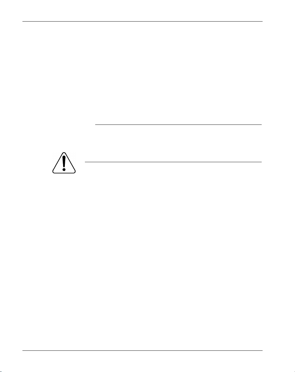
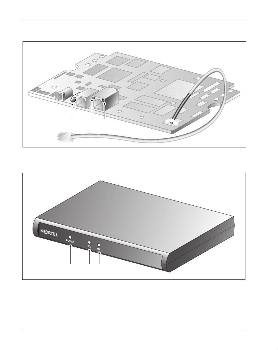
Digital Telephone IP Adapter unit LED indicator display diagrams
Digital Telephone IP Adapter circuit card
Power
LED
Tx
LED
Rx
LED
Digital Telephone IP Adapter unit
Front view
LED
Indicators
Power TX RX
G016IP
G101489IP
30 Digital Telephone IP Adapter Installation and Administration Guide
Page 31

January 2005 Digital Telephone IP Adapter description
Digital Telephone Internal IP Adapter
The Digital Telephone Internal IP Adapter provides the connections listed
below:
! a female RJ-45 connector (labeled ETHERNET) for a 10BaseT Ethernet
connection to an Internet Access Device
! a female RJ-11 connector (labeled LINE) for an analog connection to the
PSTN
This connector is not used for the Digital Telephone Internal IP Adapter
circuit card.
! a male RJ-11 connector on an approximately six-inch TCM cable for the
connection between the circuit card and the digital telephone.
Digital Telephone External IP Adapter
The Digital Telephone External IP Adapter provides the connections listed
below:
! a female RJ-45 connector (labeled ETHERNET) for a 10BaseT Ethernet
connection to an Internet Access Device
! a female RJ-11 connector (labeled LINE) for an analog connection to the
PSTN
This connector is not used for the Digital Telephone External IP Adapter
unit.
! a female RJ-11 connector (labeled D PHONE) for a connection to the
digital telephone
! a DB-9 connector (labeled ADMIN) provides an RS-232 connection to the
serial port of a PC
Note: The ADMIN port on the Digital Telephone External IP Adapter is for
field service use only.
Digital Telephone IP Adapter Installation and Administration Guide 31
Page 32

Digital Telephone IP Adapter description Standard 2.1
Universal power supply support - Digital Telephone Internal IP Adapter
The Digital Telephone Internal IP Adapter requires a 0.5A/24V power supply.
To order the power supply from your Nortel distributor, request part number
NTDR91xx. (The “xx” represents the vintage and can vary.) The design of this
power supply, shown in the following illustration, accommodates North
American, British (U.K.), and European standards.
Digital
Telephone
Internal IP
Adapter
circuit card
Digital Telephone
IP Adapter
cable
To wall
outlet
Power cable
32 Digital Telephone IP Adapter Installation and Administration Guide
Power supply
G017
Page 33

January 2005 Digital Telephone IP Adapter description
Universal power supply support - Digital Telephone External IP Adapter
The Digital Telephone External IP Adapter requires a 0.5A/24V power supply.
To order the power supply from your Nortel distributor, request part number
NTDR91xx. (The “xx” represents the vintage and can vary.) The design of this
power supply, shown in the following illustration, accommodates North
American, British (U.K.), and European standards.
Digital Telephone External IP Adapter unit
Digital Telephone IP
Adapter unit
cable
To wall
outlet
Power cable
Digital Telephone IP Adapter Installation and Administration Guide 33
Power supply
G101532IP
Page 34

Digital Telephone IP Adapter description Standard 2.1
Internet Access Device description
If you are using a 10BaseT Ethernet LAN at the remote site, you can connect the
Digital Telephone IP Adapter unit to any high-speed Internet Access device. The
following are some commonly-used devices:
! ISDN Basic Rate Interface (BRI) router
A BRI router is designed to send voice and data traffic across an ISDN line.
! digital subscriber line (xDSL) modem
An xDSL modem transmits digital information at high bandwidth on
existing phone lines. The xDSL modem can send and receive data at a rate
of 512 Kbps to 6 Mbps. An example, is the 1-meg modem.
! cable modem
A cable modem is used on cable TV lines so that customers can dial up to
their Internet service providers over a cable line, instead of a telephone line.
Refer to the Remote Gateway 9100 Series Network Engineering Guidelines
(NTP 555-8421-103) for detailed information on the interaction of the Digital
Telephone IP Adapter unit with the IP Network.
34 Digital Telephone IP Adapter Installation and Administration Guide
Page 35

January 2005 Digital Telephone IP Adapter description
Connection options
Communications between the Digital Telephone IP Adapter unit in your office
and the host PBX takes place using 10BaseT Ethernet interface to an Internet
Access Device (IAD) on a corporate wide area network (WAN). This section
provides a description of this connection.
10BaseT Ethernet interface
The Digital Telephone IP Adapter unit uses Nortel proprietary Voice over IP
(VoIP) technology over the IP network to the host PBX. Voice data is forwarded
as UDP/IP packets and the signalling data as TCP/IP packets. You can connect
the Ethernet interface to an Internet Access Device such as a BRI router, an
xDSL modem, or cable modem. For more information, refer to the “Internet
Access Device description” on page 34.
Note: The Digital Telephone IP Adapter uses a half-duplex 10BaseT Ethernet
connection.
Digital Telephone IP Adapter Installation and Administration Guide 35
Page 36

Digital Telephone IP Adapter description Standard 2.1
How Digital Telephone IP Adapter units work
There are two major components to the Digital Telephone IP Adapter units.
They are:
1. the Digital Telephone Internal or External IP Adapter unit located at the
remote location
2. the RLC located on the host PBX
These two components, along with the connection options described on page 35,
extend the host PBX services to a remote user.
IP network diagram
Digital Telephone
External IP Adapter unit
Digital telephone
Ethernet
Internet
Access
Device
Internet
OR
Corporate
WAN
Digital Telephone Internal
IP Adapter circuit card
Host PBX
Reach Line Card
G018
36 Digital Telephone IP Adapter Installation and Administration Guide
Page 37

January 2005 Digital Telephone IP Adapter description
Outgoing call process
To place outgoing calls, users can either pick up the handset on the telephone or
press the line key. For a detailed description of the outgoing call process, refer to
the sample illustrations beginning on page 38.
Incoming call process
When someone places a call through the host PBX to a Digital Telephone IP
Adapter unit, the RLC connects to the remote unit. The host PBX then
completes the call normally. If the RLC cannot establish a connection, the call
rings until the host PBX forwards the call to voice mail. Refer to Chapter 6,
“Using the digital telephone”, for a more detailed description of the incoming
call process.
Note: After a power failure, a Digital Telephone Internal or External IP Adapter
unit comes back online and answers all incoming calls. To prevent the unit from
staying online indefinitely after a power outage, enter a single Offline command
in the unit's Online/Offline table for the week. Use SPRE codes to go online and
offline. For more information on the Online/Offline table, refer to “Online/
Offline Table” on page 50. For more information on SPRE codes, refer to
“Going online and offline” on page 152.
Host-controlled call mode
When you place a call to someone at the host site, or when someone from the
host site calls you, the call is in host-controlled call mode. Calls in hostcontrolled mode are routed through the host PBX. Refer to the sample
illustrations beginning on page 38.
Digital Telephone IP Adapter Installation and Administration Guide 37
Page 38

Digital Telephone IP Adapter description Standard 2.1
Call scenario 1: host-controlled—corporate internal call
The following diagram shows how a call is routed when placing a hostcontrolled call over the IP network to the corporate office:
Host-controlled call (corporate internal call)
Remote site
Digital Telephone
External IP Adapter unit
Digital telephone
OR
Ethernet
Digital Telephone
Internal IP Adapter circuit card
WAN
InternetCorporate
Host location
Host
PBX
C
1
Host
stations
B
RLC
A
Internet
Access
Device
Voice over IP call
G019IP
Calls work the same in reverse, from the host PBX site to the Digital Telephone
IP Adapter unit site.
38 Digital Telephone IP Adapter Installation and Administration Guide
Page 39

January 2005 Digital Telephone IP Adapter description
Voice over IP network call
1 The Digital Telephone IP Adapter user lifts the handset (item A).
Result: The Digital Telephone IP Adapter user hears a dial tone. This
indicates a successful connection to the RLC over the IP network (item B).
2 The Digital Telephone IP Adapter user dials a telephone number, such as
the extension number of host station 1.
Result: The Digital Telephone IP Adapter unit sends the dialed digits as
packets through the IP network to the Ethernet network or Corporate WAN
to the RLC. The RLC converts the packets to the format required by the
host PBX.
3 The host PBX then converts the data to voice and routes the call to host
station 1 (item C).
Note: Item notations in parentheses refer to circled markers in the diagram on
page 38.
Digital Telephone IP Adapter Installation and Administration Guide 39
Page 40

Digital Telephone IP Adapter description Standard 2.1
Call scenario 2: host-controlled—corporate external call
The following diagram shows how a call is routed when placing a hostcontrolled call to a party outside the organization using a Digital Telephone IP
Adapter unit.Calls work the same in reverse, from the host PBX site to the
Digital Telephone IP Adapter unit site.
Host-controlled call (corporate external call)
Remote site
Digital Telephone
External IP Adapter unit
Digital telephone
OR
Ethernet
Digital Telephone
Internal IP Adapter circuit card
WAN
Host location
Host
PBX
Host
stations
40 Digital Telephone IP Adapter Installation and Administration Guide
InternetCorporate
1
2
B
RLC
A
Internet
Access
Device
Voice over IP call
G020IP
Page 41

January 2005 Digital Telephone IP Adapter description
Voice over IP network call
1 The Digital Telephone IP Adapter user lifts the handset (item A).
Result: The Digital Telephone IP Adapter user hears a dial tone. This
indicates a successful connection to the RLC over the IP network and the
corporate WAN (item B).
2 The Digital Telephone IP Adapter user dials the external telephone number.
Result: The Digital Telephone IP Adapter unit sends the dialed digits as
packets across the Ethernet network. The packets go through the IP
network and the corporate WAN, to the RLC. The RLC converts the
packets to the format required by the host PBX. The host PBX then
converts the data to voice and routes the call to the called party (host
stations 1 and 2).
Note: Item notations in parentheses refer to circled markers in the diagram on
page 40.
Digital Telephone IP Adapter Installation and Administration Guide 41
Page 42

Digital Telephone IP Adapter description Standard 2.1
System security
There are two levels of security that you can set to control access from Digital
Telephone IP Adapter units to the RLC on the host PBX. This section describes
these security levels and how you can manage them using Remote Gateway
9100 Series Configuration Manager.
No security
When no security measures are used, the RLC accepts incoming calls from all
Digital Telephone IP Adapter units.
Use this level with caution as it exposes the RLC to unauthorized use. For
example, No security allows a user from an unauthorized remote site can
accidentally, or intentionally, connect to the RLC. With this connection made,
the unauthorized user can now place long distance phone calls through the RLC
and the host PBX.
Security identifier
When you choose the security identifier level of security, the Digital Telephone
IP Adapter automatically sends its configured security identifier (password) for
each connection request. The RLC compares the identifier configured to the
RLC port with the identifier assigned to the Digital Telephone IP Adapter. If the
identifiers match, then the RLC grants the requested connection.
If the identifiers do not match, then the RLC records an event in the Digital
Telephone IP Adapter system log. You can view the system log in Remote
Gateway 9100 Series Configuration Manager. The telephone displays
HOSTLESS MODE,ïindicating that communications with the host PBX are
down.
42 Digital Telephone IP Adapter Installation and Administration Guide
Page 43

January 2005 Digital Telephone IP Adapter description
Telephones
This section lists the telephones, features, and modules supported by the Digital
Telephone IP Adapter unit.
Supported digital telephones
Digital Telephone IP Adapter units support the following digital telephone sets
with display:
! M2008D ! M2616D ! M3902 ! M3905
! M2008HFD ! M3310 ! M3903
! M2216D ! M3820 ! M3904
Your digital telephone must have a one or two-line display in order to configure
the Digital Telephone IP Adapter unit with the telephone display menu.
Notes:
1. Because it is a discontinued model, the M2616CT cordless digital
telephone set is no longer supported.
2. When you update the message on the host PBX that displays when the
digital telephone set is idle, you must unplug the digital telephone set and
plug it back for the change to take effect.
3. You must re-boot a Digital Telephone IP Adapter unit after unplugging and
re-plugging the telephone cord of its associated digital telephone set.
4. Auto Answer Back (AAB) activation on M26xx series digital telephone
sets on Remote Gateway 9100 Series units connected to CS 2100 PBXs
does not produce a dial tone. The digital telephone sets operate properly,
but no dial tone is present. To produce dial tone in this situation, configure
the port on the RLC as a TAPI port.
Digital Telephone IP Adapter Installation and Administration Guide 43
Page 44

Digital Telephone IP Adapter description Standard 2.1
Notes for M39xx series digital telephone sets:
1. To label the Local Keys on M3902 digital telephone sets, use the options
key on the digital telephone set itself.
2. If you downgrade the host PBX to a release prior to X11 release 25.40, you
must also downgrade any new or upgraded M39xx digital telephone sets so
that the Meridian 1 PBX can support them. This applies to digital telephone
sets attached to Remote Gateway 9100 Series units and Extended Digital
Line Cards.
3. The M3904 digital telephone set Key Map fails using Virtual Office on
Remote Gateway 9100 Series. Upgrade the digital telephone set’s firmware
to version 8.3 to resolve this problem.
4. Uploading and downloading M3904 and M3905 firmware requires the
most recent digital telephone set hardware. To resolve problems following
firmware uploads and downloads, including missing functionality, refer to
the User Guide and Release Notes for your particular digital telephone set.
5. Flash upgrade download times to remote M39xx digital telephone sets over
an IP network with low delay and packet loss are comparable to PBX wired
downloads.
44 Digital Telephone IP Adapter Installation and Administration Guide
Page 45

January 2005 Digital Telephone IP Adapter description
M2000 series (European models M3310 and M3820) and M39xx series
digital telephone set model and accessory compatibility
The following tables show Digital Telephone IP Adapter compatibility with
M2000 series (M3310 and M3820 European models) and M39xx digital
telephone set models and accessories:
Digital Telephone Set Models
M2008D, M2008HFD ✓✓
M2616D ✓✓
M2216D-ACD ✓✓
M2616CT Cordless Discontinued Discontinued
M3310, M3820 (Europe only) ✓✓
M3902, M3903 ✓
M3904 ✓
M3905 (ACD) ✓
M2000 series (M3310 & M3820 European models) Add-on Modules
Headsets ✓✓
External alert ✓✓
Key-based expansion module ✓✓
ATA (Analog Terminal Adapter)
MCA (Meridian Communications
Adapter)
i. The host PBX must be running software capable of supporting each digital telephone
set model used.
i
Digital Telephone
Internal IP Adapter
Digital Telephone
External IP Adapter
Digital Telephone IP Adapter Installation and Administration Guide 45
Page 46

Digital Telephone IP Adapter description Standard 2.1
M39xx series digital telephone set accessory compatibility
The following table shows Remote Gateway 9150 unit compatibility with
M39xx series digital telephone set accessories.
M39xx series Digital Telephone Set Accessories
and Add-on Modules
Headsets ✓
External alert & recording interface ✓
Key-based expansion module (22-button, up to two for
each 3904/05)
Display-based expansion module ✓
ATA (Analog Terminal Adapter)
Personal Directory PC utility ✓
Full-duplex Speakerphone ✓
CTI (Computer Telephony Integration) Adapter ✓
Digital Telephone IP
Adapter units
✓
Required footstand for Digital Telephone Internal IP Adapter units
The Digital Telephone Internal IP Adapter unit installs in the footstand of the
Meridian Digital Telephone. The required ATA/MCA footstand is standard on
Meridian Modular Telephones (M2000 series) with a date code of May 6, 1998
or later. Contact your Nortel distributor to obtain the required footstand if your
telephone has an earlier date code.
Supported telephone modules
Digital Telephone IP Adapter units support the following telephone modules:
! add-on modules to add more keys to the digital telephone
! application modules to provide more functionality to the digital telephone
Note: Digital Telephone Internal IP Adapter units do not support Meridian
Communication Adapters (MCAs) or Analog Telephone Adapters (ATAs).
46 Digital Telephone IP Adapter Installation and Administration Guide
Page 47

January 2005 Digital Telephone IP Adapter description
Supported telephone features
The Digital Telephone IP Adapter units support all features provided by the host
PBX for host-controlled calls. The following are some examples:
! ACD features
! call forward
! conference
! call waiting
! hold
! transfer
Note: Dial tone for conference and transfer can be very rough. A stutter can be
heard during a remote dial tone. This is a normal occurrence and is caused by the
DSP activating a dial tone relay.
Refer to Chapter 6, “Using the digital telephone”, for a detailed description of
the features listed above.
Computer telephony integration applications
You can use the following two types of computer telephony integration (CTI)
applications:
1. first-party CTI applications that use the Symposium Desktop Telephone
Application Programming Interface (TAPI) Service Provider
2. third-party CTI applications that use Symposium TAPI Service Provider for
M1
You can use both types with the Digital Telephone IP Adapter unit.
Digital Telephone IP Adapter Installation and Administration Guide 47
Page 48

Digital Telephone IP Adapter description Standard 2.1
Automatic Call Distribution (ACD) applications
The Digital Telephone IP Adapter supports all Nortel Automatic Call
Distribution (ACD) applications.
If an ACD agent loses communication to the Digital Telephone IP Adapter unit,
or the unit goes offline, the agent is placed in Make Set Busy (MSB) mode. This
mode logs the agent out of the ACD queue so that calls can be routed to other
ACD agents. Once you re-establish communication between the agent and the
Digital Telephone IP Adapter, the digital telephone set display shows “Set Busy
Activated”.
In addition, when an ACD agent is on a call using a Local Calling key, the
Digital Telephone IP Adapter unit sends a transparent Not Ready key press to
the host PBX and places the ACD agent’s digital telephone set in Not Ready
mode. This feature prevents the ACD agent from receiving ACD calls when
active on a local call. The Digital Telephone IP Adapter unit removes the digital
telephone set from the Not Ready mode when the agent terminates the local call.
If you are having trouble with ACD agents being logged off unexpectedly or
calls that terminate prematurely, try the following:
! Set the User On Demand Idle Timer to 90 seconds and the User On
Demand Minimum Call Timer to 1 second.
Note: You can configure these settings on the RLC’s Remote Connection
Configuration property sheet in Configuration Manager.
! Allocate a permanent connection for the ACD agents.
— On the RLC Port Configuration property sheet, click on the Configure
button for the Network Port in question.
— In the Network Port Configuration dialog box, select Permanent
Allocation.
48 Digital Telephone IP Adapter Installation and Administration Guide
Page 49

January 2005 Digital Telephone IP Adapter description
Communications system and software requirements
The following table shows the software versions necessary to run Digital
Telephone IP Adapter units on compatible Nortel’s communications systems.
Digital Telephone IP Adapter units
Communications system
Meridian 1 PBX X11 release 23 or higher
CS 1000 Release 2 or higher
CS 2100 Release MSL12 or higher
i. Requires Remote Gateway 9100 Series software version 1.5 or higher.
Supported Codecs
The following tables show the Codecs supported by the Digital Telephone IP
Adapter unit, as well as the data stream, and approximate peak bandwidth
required by each.
Digital Telephone IP Adapters
CODEC Data stream only
G.711 64 Kbps 78 Kbps
G.729A 8 Kbps 22 Kbps
i
System software version
Approximate peak bandwidth, including IP
overhead (30 ms voice packets)
Digital Telephone IP Adapter Installation and Administration Guide 49
Page 50

Digital Telephone IP Adapter description Standard 2.1
Online/Offline Table
Configure the Online/Offline table on the RLC to schedule the times that you
want to make the host PBX available to the Digital Telephone IP Adapter unit.
Note: When the Digital Telephone IP Adapter unit is in offline mode, you
cannot use it to place or receive calls.
You can define up to eight entries per day, every day of the week for each Digital
Telephone IP Adapter unit site. You can define each entry as online, offline, or
undefined for each time period entered.
You can override the settings of the Online/Offline table if the table attempts to
suspend access to the connection in the middle of a business call. You are alerted
by a tone and a display message 30, 20, and 10 seconds before the connection is
terminated. To override connection termination, you must enter the online SPRE
(Special Prefix) code on the telephone.
You can configure an online/offline table for each remote site on the RLC. Refer
to the Reach Line Card Installation and Administration Guide (NTP 555-8421-
210) for configuration information.
50 Digital Telephone IP Adapter Installation and Administration Guide
Page 51

January 2005 Digital Telephone IP Adapter description
Emergency service number
To make an emergency service call, you must use a PSTN telephone. The Digital
Telephone IP Adapter unit does not support emergency service calls.
ATTENTION!
You must place emergency service calls on a telephone that
is directly connected to a PSTN line. If you place an
emergency service call from a station that is connected to a
Digital Telephone IP Adapter unit, the RLC routes the call
through the host PBX. (The host PBX could be in a
different city.)
Digital Telephone IP Adapter Installation and Administration Guide 51
Page 52

Digital Telephone IP Adapter description Standard 2.1
Remote Gateway 9100 Series Configuration Manager
After the initial configuration is complete, you can use Remote Gateway 9100
Series Configuration Manager administration software to make configuration
changes and administer the Digital Telephone IP Adapter unit. Refer to Chapter
5, “Changing configuration settings using Configuration Manager”. The
software is a Windows-based application that is installed on your PC.
Administration tasks include the following:
! viewing the system status
! performing upgrades, backups, or restores
! making configuration changes
! changing the administration password
Note: You must use the telephone set menu to configure the Digital Telephone
IP Adapter unit for the first time. Refer to “Before you begin” on page 84 for a
detailed telephone menu description.
52 Digital Telephone IP Adapter Installation and Administration Guide
Page 53

January 2005 Digital Telephone IP Adapter description
Power requirements
This section lists characteristics of the recommended power supplies for the
Digital Telephone IP Adapter units.
Input specifications
Input specifications for the Digital Telephone IP Adapter units are as follows:
Characteristic Rating
voltage 90 - 264 VAC
frequency 47 - 63 Hz
current 0.4A maximum
Output specifications
Output specifications for the Digital Telephone IP Adapter units are as follows:
Characteristic Rating
voltage 24 VDC +/-5%
current 0.62A maximum
power 15W maximum
Digital Telephone IP Adapter Installation and Administration Guide 53
Page 54

Digital Telephone IP Adapter description Standard 2.1
54 Digital Telephone IP Adapter Installation and Administration Guide
Page 55

Chapter 2
Planning for installation
In this chapter
Physical environment 56
Administration PC 59
Network considerations 62
Deployment 64
Digital Telephone IP Adapter Installation and Administration Guide 55
Page 56

Planning for installation Standard 2.1
Physical environment
This section provides the space, temperature, cabling, and mounting information
you need to know before you install Digital Telephone IP Adapter units.
Space
Insert the Digital Telephone IP Adapter into the base of a digital telephone set.
The dimensions for the circuit card are as follows:
! 16.5 cm (6.5 inches) wide
! 8.8 cm (3.5 inches) deep
Place the Digital Telephone IP Adapter on a desk, or mount it on the wall. The
dimensions for the unit are as follows:
! 18.2 cm (7.2 inches) wide
! 9.9 cm (3.9 inches) deep
Temperature
The table on the following page describes the temperature and humidity
conditions that the Digital Telephone IP Adapter unit can withstand without any
performance degradation or damage.
56 Digital Telephone IP Adapter Installation and Administration Guide
Page 57

January 2005 Planning for installation
Specification Minimum Maximum
Normal operation
Recommended:
! Temperature (Ambient)
! Relative humidity
! 0°C (32°F)
! 10%
! 40°C (104°F)
! 95% (non-
condensing)
Storage
Recommended temperature -40°C (-40°F) 70°C (158°F)
Relative humidity 5% 95% RH (non-
condensing)
Power consumption
Vo l t a g e
Current
24VDC
0.3A
Digital Telephone IP Adapter Installation and Administration Guide 57
Page 58

Planning for installation Standard 2.1
Mounting options
Place the Digital Telephone External IP Adapter on a desk, or mount the unit on
the wall. If mounting on the wall, make sure that the chosen location allows you
to easily view the LED indicators on the front panel.
ATTENTION!
Installation on the wall must be completed using standard
telephony installation practices.
Cables included with the Digital Telephone Internal IP Adapter
The Digital Telephone Internal IP Adapter package includes a power cord and
power supply.
Cables included with the Digital Telephone External IP Adapter
The Digital Telephone Internal IP Adapter package includes the following
cables:
! 1.83 meter (6-foot) RJ-11 telephone cord
! a power cord and power supply
Cables you must supply yourself
The following cables used to establish the network connections are industrystandard cables and are not provided in the Digital Telephone External IP
Adapter package.
! Ethernet cable (CAT 5)
! telephone cable
! serial cable for the Digital Telephone External IP Adapter
You must obtain these cables from your local cable supplier.
58 Digital Telephone IP Adapter Installation and Administration Guide
Page 59

January 2005 Planning for installation
Administration PC
This section describes the way that you can connect an administration terminal
to the Digital Telephone IP Adapter unit. It also describes the hardware and
software requirements for using the Configuration Manager administration
software.
Connection options
The Digital Telephone IP Adapter system includes the Configuration Manager
software that enables you to configure, administer, and upgrade the Digital
Telephone IP Adapter unit. You can connect to Digital Telephone IP Adapter
unit with Telnet to use Configuration Manager, or using the digital telephone set
menu.
You can access Configuration Manager using a 10BaseT Ethernet connection for
ongoing administration and upgrade of Digital Telephone IP Adapter units.
Note: Use the telephone set menu for first-time configuration of Digital
Telephone IP Adapter units.
Ethernet connection
Once you configure the Digital Telephone IP Adapter unit with its IP interface
information, the following can occur:
! You can establish communication between the Digital Telephone IP
Adapter unit and the RLC (that is, calls can be routed over the data link
between the two).
! You can administer the Digital Telephone IP Adapter unit over the data link
between the unit and the RLC. For more information, refer to Appendix ,
“Administering multiple nodes in the network,”.
Digital Telephone IP Adapter Installation and Administration Guide 59
Page 60

Planning for installation Standard 2.1
Administering multiple nodes in the network
If you are responsible for administering one or more Digital Telephone IP
Adapter units and the RLC on the host PBX, you can access them and the RLC
from anywhere on the network.
Note: You do not have to install separate administration PCs for the RLC and
the Digital Telephone IP Adapter unit(s). You can use one administration PC to
administer all units in the Remote Gateway 9100 Series network.
Windows PC requirements
To use Configuration Manager, the administration PC must:
! be an IBM-compatible PC
! use a Windows 95, 98, NT Workstation 4.0, Millennium Edition (ME),
2000 Professional, or XP (Professional and Home Edition) operating
system with the Microsoft TCP/IP networking component installed
! be equipped with a CD-ROM drive
! be equipped with a 10BaseT Ethernet interface card (this provides access to
the Ethernet network)
! have an available COM port if you wish to use the RS-232 serial port to
establish a direct serial connection
! be equipped with a pointing device, such as a mouse
! have 32 Mbytes of RAM for Windows 95, 98, and ME, or 64 Mbytes of
RAM for Windows NT Workstation 4.0, 2000 Professional, and XP
(Professional and Home Edition
! have 48 Mbytes of available storage for Windows 95, 98 and ME, or 64
Mbytes of available storage for Windows NT Workstation 4.0, 2000
Professional, and XP (Professional and Home Edition)
Note: Configuration Manager does not support any of the Win32 Server
versions of Microsoft Windows.
60 Digital Telephone IP Adapter Installation and Administration Guide
Page 61

January 2005 Planning for installation
Trivial File Transfer Protocol (TFTP) server
A TFTP server is required for performing firmware upgrades and configuration
uploads. You can use any TFTP server application. TFTP server applications are
available from the Internet.
Year 2000 compliance
The Digital Telephone IP Adapter unit and Configuration Manager software are
Year 2000 compliant. However, you must ensure that the administration PC is
Year 2000 compliant by verifying that the Windows operating system is shown
in this table:
Operating system Year 2000 compliance requirement
Windows 95 Version 95b
Windows 98 OK as is
Windows NT Workstation 4.0 Service Pack 5 or higher
Windows 2000 Ok as is
Windows ME Ok as is
Windows XP OK as is
Optivity Telephony Manager and Configuration Manager
Nortel does not guarantee that Optivity Telephony Manager (OTM) and the
Configuration Manager can operate simultaneously on the same administration
PC. Simultaneous running of these two applications has not been tested and is,
therefore, not supported.
Digital Telephone IP Adapter Installation and Administration Guide 61
Page 62

Planning for installation Standard 2.1
Network considerations
Refer to the Remote Gateway 9100 Series Network Engineering Guidelines
(NTP 555-8421-103) for detailed information on planning and preparing your
network for the addition of IP Adapter units. The Digital Telephone IP Adapter
unit communicates with the host PBX using the IP network. To use the Digital
Telephone IP Adapter unit in these networks, you must consider the issues
described in this section.
IP addressing and routing
To place and receive calls over the IP network, you must:
! physically connect the Digital Telephone IP Adapter unit to the IP network
! assign a unique IP address and a subnet mask to the Digital Telephone IP
Adapter unit, unless using Dynamic Host Configuration Protocol (DHCP)
Note: Similarly, you must assign a subnet mask, gateway, and unique IP
address to the RLC on the host PBX.
! have the ability to send and receive traffic to and from the RLC on the host
PBX
Determining DHCP assigned IP addresses
If you use DHCP at the remote location, determine the Remote Gateway 9100
Series unit's IP address by checking the Network statistics for the RLC through
Configuration Manager. Log onto Configuration Manager, choose the RLC as
the Device Type, and then access Alarms/Stats/Logs
Enter the Unit ID of the Remote Gateway 9100 Series unit that you want to
review the statistics for. The DHCP assigned IP address displays at the top of the
window.
Note: If you are using a Network Address Translation (NAT) router at the
remote location, the IP address provided is a NAT address. To access the Remote
Gateway 9100 Series unit using Telnet, ensure that the NAT router allows Telnet
access to TCP port 23, and for upgrades, TCP port 69.
62 Digital Telephone IP Adapter Installation and Administration Guide
→ Network Statistics.
Page 63

January 2005 Planning for installation
Network diagram
The following diagram shows the Digital Telephone IP Adapter unit’s position
in an IP network.
Internal
network
10. 3.1.1
10. 3.1.2
Management
port (optional)
Router
Host
PBX
RLC
10. 2.1. 1
10. 2 .1.310 .3.1. 3
Ethernet
network
Digital Telephone
Internal IP Adapter circuit card
Router
10. 2.1. 10 10. 4.1.2
Data modem
Digital Telephone
External IP Adapter unit
10.1.1.6 10.1.1.5
Data modem
10.1.1.4
Corporate
WAN
10.1.1.1
10.1.1.2 10.1.1.3
User's
PC
User's
PC
G101520IP
Digital Telephone IP Adapter Installation and Administration Guide 63
Page 64

Planning for installation Standard 2.1
Deployment
This section presents the Digital Telephone IP Adapter unit deployment models
(options) that are supported by Nortel.
Transport media
You can only configure the Digital Telephone IP Adapter unit on the RLC to use
the IP network. For further details on this configuration, refer to Priority under
Remote Port Configuration in the Reach Line Card Installation and
Administration Guide (NTP 555-8421-210).
Network Address Translation (NAT)
Some network routers run the NAT protocol that allows multiple devices in the
IP network to share the same broadband IP address. An alternative to running
the NAT protocol is to have the network administrator provide each device with
its own broadband IP address.
Digital Telephone IP Adapter units support NAT functionality, if this
functionality is enabled on your network. You can only connect a single Digital
Telephone IP Adapter unit behind a NAT router. You can connect multiple
Digital Telephone IP Adapter units behind a Network Address and Port
Translation (NAPT) router. If you are not sure whether yours is a NAT router or
a NAPT router, check with your vendor.
You must configure your Digital Telephone IP Adapter unit for IP permanent
allocation if it is connected behind a NAT router. You can assign a static IP
address to your Digital Telephone IP Adapter unit, or you can use DHCP to
obtain its IP address.
Translation tables within NAT routers control the communication path from the
private network to the public network. Most NAT devices contain timers that
monitor the translation table entries. Each time the device uses a translation table
entry, the timer restarts. Individual table entries are deleted if the
communications path is not used and the timer expires.
64 Digital Telephone IP Adapter Installation and Administration Guide
Page 65

January 2005 Planning for installation
It is possible, when using a Digital Telephone IP Adapter unit behind a NAT
device, that prolonged periods of silence cause the NAT translation table entries
to clear and drop the audio path. An example of this is a remote user listening to
a conference call with the user’s digital telephone set on mute. After five
minutes (the default NAT translation table timer on many NAT routers) the
router drops the voice path. The remote user is no longer able to hear the
conference. To restore the NAT table entry and recover the audio path, the
remote user can go off mute and speak into the digital telephone set.
To prevent the NAT translation table from dropping the audio path:
! configure the translation tables on the NAT router with a large timer value
(for example, two hours)
! configure a static translation table entry for UDP port 20480
IP deployment
Before deploying your Digital Telephone IP Adapter unit, ensure that you
engineer the IP network properly. You can configure a permanent (Model 1) or
on-demand (Model 2) IP connection. The following guidelines describe
requirements, conditions, and characteristics of each supported IP deployment
option:
Model 1: IP permanent
If using DSL or a cable modem, configure an IP permanent connection.
! The Digital Telephone IP Adapter unit re-establishes its TCP/IP signaling
session to the RLC once per minute.
! The Digital Telephone IP Adapter unit supports both static IP and, through
DHCP, dynamic IP addressing
! Do not configure a remote IP address on the RLC.
! One virtual private network (VPN) supports multiple Digital Telephone IP
Adapter units.
! One Network Address Translation (NAT) router supports only one Digital
Telephone IP Adapter unit.
! One Port number and Network Address Translation (PNAT) router supports
multiple Digital Telephone IP Adapter units.
Digital Telephone IP Adapter Installation and Administration Guide 65
Page 66

Planning for installation Standard 2.1
! The RLC requires an IP address that the Digital Telephone IP Adapter unit
can access.
Model 2: IP on-demand
If your BRI routers incur toll charges, configure an IP on-demand connection.
! TCP/IP signaling sessions between the RLC and the Digital Telephone IP
Adapter unit close when calls end.
! Configure a static IP address for the Digital Telephone IP Adapter unit on
the RLC for best service.
! IP on-demand configuration supports VPNs.
! IP on-demand configuration does not support NAT or PNAT routers.
! Both the RLC and Digital Telephone IP Adapter unit require IP addresses
that are accessible from the other unit.
66 Digital Telephone IP Adapter Installation and Administration Guide
Page 67

Chapter 3
Installing the Digital Telephone IP Adapter unit
In this chapter
Preparing for installation 68
Installing the Digital Telephone Internal IP Adapter circuit card 70
Installing the Digital Telephone External IP Adapter unit 76
Testing the network connection 82
Digital Telephone IP Adapter Installation and Administration Guide 67
Page 68

Installing the Digital Telephone IP Adapter unit Standard 2.1
Preparing for installation
This section shows you how to prepare for the installation of the Digital
Telephone IP Adapter unit.
General Safety
The following is a list of general safety measures to be considered when
installing the Digital Telephone IP Adapter unit.
! Do not ignore the warnings, in the guide, about the risks related to installing
and handling hardware. For a description of the types of warnings this
guide provides, refer to “Conventions used in this guide” on page xx in the
Preface.
! Follow these safety precautions at all times to avoid damage or injury:
— Plug the Digital Telephone IP Adapter unit into a properly grounded
power source to reduce the possibility of electric shock and damage to
the unit or network.
— Ensure that nothing rests on connection cables, and that cables cannot be
tripped over or stepped on.
! Protect the equipment against Electrostatic discharge (ESD). ESD affects
the performance and decreases the useful life of system components. ESD
can seriously damage component parts such as circuit cards. Implement the
following precautions that are recommended by computer and telephone
equipment manufacturers:
— Remove items that generate static charge from the installation site.
— Use antistatic spray if the site is carpeted.
— Ground yourself before handling any equipment.
68 Digital Telephone IP Adapter Installation and Administration Guide
Page 69

January 2005 Installing the Digital Telephone IP Adapter unit
Required hardware and software tools
You need the following tools for hardware and software installation:
! antistatic ESD wrist strap (recommended)
! Phillips-head screwdriver and two number eight wood screws (if you want
to mount the Digital Telephone External IP Adapter on the wall)
! Remote Gateway 9100 Series Product CD-ROM
! PC with a CD-ROM drive or an Internet connection for obtaining software,
firmware, and documentation updates
! TFTP server application installed on the PC
The TFTP server is required for performing firmware upgrades. If a TFTP
server is currently not installed, you can obtain one from the Internet.
Unpacking and inspecting the equipment
Before you install the Digital Telephone IP Adapter unit, ensure that the
following package contents are all present and are not damaged:
! one Digital Telephone Internal IP Adapter or Digital Telephone External IP
Adapter
! one power cord and power supply for each Digital Telephone IP Adapter
unit
! one six-foot RJ-11 telephone cable for each Digital Telephone External IP
Adapter unit
! one installation kit for each Digital Telephone Internal IP Adapter circuit
card. Each installation kit includes the following:
— two ferrite beads
—one overlay
— two mounting screws (used to attach the circuit card to the foot stand)
! Remote Gateway 9100 Series and RLC Release Notes (NTP 555-8421-102)
! Digital Telephone IP Adapter Quick Start Guide
Digital Telephone IP Adapter Installation and Administration Guide 69
Page 70

Installing the Digital Telephone IP Adapter unit Standard 2.1
Installing the Digital Telephone Internal IP Adapter circuit card
Before you can install the Digital Telephone Internal IP Adapter circuit card,
you must first remove the footstand of the digital telephone. For more
information about supported telephone footstands, refer to “Required footstand
for Digital Telephone Internal IP Adapter units” on page 46.
Note: You can only add the Digital Telephone Internal IP Adapter circuit card to
digital telephones that have an ATA/MCA footstand. To obtain an ATA/MCA
footstand, contact your Nortel distributor.
Removing the footstand of the digital telephone set
To remove the footstand of the digital telephone set:
1 Disconnect the telephone-side connection of the RJ-11 TCM telephone
cable. The other end of this cable connects to the wall jack.
2 Place the telephone on a flat surface with the keypad facing downward.
Note: Ensure that you are grounded with an approved ESD strap.
70 Digital Telephone IP Adapter Installation and Administration Guide
Page 71

January 2005 Installing the Digital Telephone IP Adapter unit
3 Unscrew and remove the footstand of the digital telephone.
Note: Refer to “A” in the following diagram.
B
A
G101492
4 Punch out the front panels in the footstand of the telephone to make the
connections accessible when you install the Digital Telephone Internal IP
Adapter circuit card.
Note: Refer to “B” in the preceding diagram.
Inserting the Digital Telephone Internal IP Adapter circuit card
To insert the Digital Telephone Internal IP Adapter circuit card into your digital
telephone:
1 Remove the Digital Telephone Internal IP Adapter circuit card from the
antistatic bag.
2 Insert the leading edge of the Digital Telephone Internal IP Adapter circuit
card under the two brackets on the footstand.
Note: Refer to “C” in the following diagram for the location of the brackets.
Digital Telephone IP Adapter Installation and Administration Guide 71
Page 72

Installing the Digital Telephone IP Adapter unit Standard 2.1
3 Use both hands to push forward until the circuit card snaps into place under
the brackets.
Note: Two holes on either side of the circuit card are now aligned with the
corresponding holes on the footstand.
C
circuit card
D
G101493
4 Attach the Digital Telephone Internal IP Adapter circuit card to the footstand
with the screws supplied in the Installation Kit.
Note: Refer to “D” in the diagram on page 72.
5 Plug the male RJ-11 connector on the loose end of the Meridian Line Cord
attached to the Digital Telephone Internal IP Adapter circuit card into the
jack on the telephone.
6 Re-attach the footstand to the bottom of the telephone.
7 Apply the overlay identifying the power connection and the jack connecting
your Ethernet for IP network connectivity.
72 Digital Telephone IP Adapter Installation and Administration Guide
Page 73

January 2005 Installing the Digital Telephone IP Adapter unit
Installing ferrite beads
The Digital Telephone Internal IP Adapter circuit card installation kit contains
two ferrite beads. Ferrite beads protect the Ethernet and power supply cable
from electromagnetic interference (EMI). The two heavy pieces of ferrite come
in a plastic-hinged cover that forms a block and has a hole in the middle for the
cable to pass through. You must install the ferrite bead close to the plug that
connects to the Digital Telephone Internal IP Adapter circuit card.
To install the ferrite beads for both the Ethernet cable and the power supply
cable:
1 Open the plastic latch at the side of the ferrite bead.
2 Lay a cable across the middle of the ferrite bead.
The ferrite bead must be close to the cable connector.
3 Loop the cable tightly around the ferrite bead.
There must 2 loops of Ethernet cable around the ferrite bead (the Ethernet
cable lays across the ferrite bead 3 times).
There must be 3 loops of power supply cable around the ferrite bead (the
power supply cable lays across the ferrite bead 4 times).
4 Close and latch the ferrite bead.
Note: You may need to adjust the cable loops to make them as tight as
possible.
Digital Telephone IP Adapter Installation and Administration Guide 73
Page 74

Installing the Digital Telephone IP Adapter unit Standard 2.1
Connecting the Digital Telephone Internal IP Adapter circuit card
Ensure that you have obtained the following telephone and Ethernet cables for
your network:
! Ethernet cable
If you are connecting the Digital Telephone Internal IP Adapter circuit card
to a hub, you need a standard CAT5 unshielded twisted-pair (UTP) straightthrough Ethernet cable. The cable must be no longer than 100 meters (325
feet).
Digital Telephone IP Adapter
circuit card
G101482IP
Note: These cables are not supplied in the Digital Telephone Internal IP Adapter
package.
74 Digital Telephone IP Adapter Installation and Administration Guide
Page 75

January 2005 Installing the Digital Telephone IP Adapter unit
Complete the following procedure:
1 If you want to route calls over the IP network or administer the Digital
Telephone Internal IP Adapter circuit card with Configuration Manager,
connect the circuit card to the Ethernet network by making the following
connections:
a. Connect one end of the RJ-45 Ethernet cable to the ETHERNET
connector on the Digital Telephone Internal IP Adapter circuit card.
b. Connect the other end to either an Ethernet hub or network router.
2 Connect the Digital Telephone Internal IP Adapter circuit card to the power
source as follows:
a. Connect the appropriate cord on the power transformer to the power
connector on the Digital Telephone Internal IP Adapter circuit card.
b. Plug the power connector into an uninterruptible power supply (UPS) or
wall outlet.
Powering up the Digital Telephone Internal IP Adapter circuit card
As soon as you connect the Digital Telephone Internal IP Adapter circuit card to
the power source, the circuit card begins to power up.
During power-up, the Digital Telephone Internal IP Adapter circuit card
performs a self-test. The power LED flashes three times to verify all critical
functionality.
If the Digital Telephone Internal IP Adapter circuit card completes a successful
self-test, the telephone display shows one of the following messages:
! A time and date, if connected to a PBX.
! HOSTLESS MODE, if not connected to a PBX.
Note: The ETHERNET TX and RX LEDs flash only in response to transmit and
receive activity.
Digital Telephone IP Adapter Installation and Administration Guide 75
Page 76

Installing the Digital Telephone IP Adapter unit Standard 2.1
Installing the Digital Telephone External IP Adapter unit
You can install the Digital Telephone External IP Adapter unit on a desk or on
the wall. The unit has the following dimensions:
! 18.2 cm (7.2 inches) wide
! 9.9 cm (3.9 inches) deep
! 2.544 cm (1 inch) high
Note: If you want to mount the Digital Telephone External IP Adapter unit on
the wall, you must provide your own mounting hardware.
Installing the Digital Telephone External IP Adapter unit on a desk
To install the Digital Telephone External IP Adapter unit on a desk:
1 Turn the Digital Telephone External IP Adapter unit upside down.
2 Affix the rubber feet to the bottom of the Digital Telephone External IP
Adapter unit.
Note: Ensure the rubber feet are securely fastened.
3 Place the Digital Telephone External IP Adapter unit in the desired location.
Installing the Digital Telephone External IP Adapter unit on the wall
You need the following tools:
! a tape measure
! a screwdriver
! two long screws (to ensure the unit is securely mounted)
Note: Do not affix the rubber feet to the bottom of the Digital Telephone
External IP Adapter unit. Otherwise, the unit cannot be mounted flush against
the wall.
76 Digital Telephone IP Adapter Installation and Administration Guide
Page 77

January 2005 Installing the Digital Telephone IP Adapter unit
Ensure that your chosen location meets the following criteria:
! The LED indicators on the front panel must be easily viewed.
! There must be enough space to accommodate the cables when they are
connected to the Digital Telephone External IP Adapter unit.
Refer to the following diagram.
G023IP
Digital Telephone IP Adapter Installation and Administration Guide 77
Page 78

Installing the Digital Telephone IP Adapter unit Standard 2.1
Complete the following procedure:
1 Choose the location on the wall where you want to mount the Digital
Telephone External IP Adapter unit.
2 Use the pre-drilled screw slots on the bottom of the Digital Telephone
External IP Adapter unit as a guide to measure and mark the location on
the wall for each mounting screw.
The measurements between the screw slots are as follows:
! from front to back panels: 2.54 cm (1 in.)
! from side to side: 15.8 cm (6.25 in.)
3 Mount the screws.
Note: Do not screw the screws all the way in. Stop when the heads are
about 5 mm (1/8 inch) from the wall.
4 Mount the Digital Telephone External IP Adapter unit on the screws, then
gently pull it down so the screws slide into the narrow portion of the screw
slots.
Note: Do not let go yet.
5 Make sure that the Digital Telephone External IP Adapter unit is securely
mounted.
WARNING
Risk of equipment damage
.
Ensure that you fasten the Digital Telephone External IP Adapter
unit securely to the wall. Falls can damage the unit.
78 Digital Telephone IP Adapter Installation and Administration Guide
Page 79

January 2005 Installing the Digital Telephone IP Adapter unit
Connecting the Digital Telephone External IP Adapter unit
Obtain the following cables for your network. These cables are not supplied.
! Ethernet cable
If you are connecting the Digital Telephone External IP Adapter unit to a
hub, you need a standard CAT5 unshielded twisted-pair (UTP), straightthrough Ethernet cable. Ensure that this cable is no longer than 100 meters
(325 feet) in length.
Note: Place digital telephones no farther than 1230.7 meters (4000 feet) from
the Digital Telephone External IP Adapter unit.
The following diagram shows the connections on the back panel of the Digital
Telephone External IP Adapter unit.
Digital Telephone External IP Adapter unit
Rear view
connectors
Power Analog
line
Digital Telephone IP Adapter Installation and Administration Guide 79
Ethernet ADMIN Digital
phone
G101490IP
Page 80

Installing the Digital Telephone IP Adapter unit Standard 2.1
Connecting the Digital Telephone External IP Adapter unit to the network
To connect the Digital Telephone External IP Adapter unit to the network:
WARNING
Risk of equipment damage
.
1 Add the Digital Telephone External IP Adapter unit to your Ethernet network
by making the following connections:
a. Connect one end of the Ethernet cable to the ETHERNET connector on
b. Connect the other end to either an Ethernet hub or a network router.
2 Connect the Digital Telephone External IP Adapter unit to the power source
as follows:
To prevent damage to the Digital Telephone External IP
Adapter unit, ensure that the power source to the unit is turned
off until you complete all connections.
the Digital Telephone External IP Adapter
unit.
a. Connect the appropriate plug on the power transformer to the power
connector on the Digital Telephone External IP Adapter unit.
b. Plug the power connector into an uninterruptible power supply (UPS) or
wall outlet.
3 Connect the Digital Telephone External IP Adapter unit to the digital
telephone as follows:
a. Connect one plug of the telephone cable supplied with the Digital
Telephone External IP Adapter unit to the jack marked DIGITAL
PHONE on the rear panel of the Digital Telephone External IP Adapter
unit.
b. Plug the other end of this cable to the jack on the digital telephone.
80 Digital Telephone IP Adapter Installation and Administration Guide
Page 81

January 2005 Installing the Digital Telephone IP Adapter unit
Powering up the Digital Telephone External IP Adapter unit
As soon as you connect the Digital Telephone External IP Adapter unit to the
power source, the unit begins to power up.
During power-up, the Digital Telephone External IP Adapter unit performs a
self-test. The power LED flashes three times to verify all critical functionality,
including:
! RAM memory test
! Flash checksum validation
If the Digital Telephone External IP Adapter unit completes a successful selftest, the telephone display shows one of the following messages:
! A time and date, if connected to a PBX.
! HOSTLESS MODE, if not connected to a PBX.
Note: The ETHERNET TX and RX LEDs flash only in response to transmit and
receive activity.
Digital Telephone IP Adapter Installation and Administration Guide 81
Page 82

Installing the Digital Telephone IP Adapter unit Standard 2.1
Testing the network connection
After you have installed the hardware and performed initial configuration, use
the following methods to test the network connectivity:
! Perform a PING test.To perform this test, the following must be true:
— You must be physically connected to the network.
— You must be logged on to Configuration Manager.
Refer to “Using Configuration Manager’s PING” on page 221 for complete details on performing a Configuration Manager PING.
! Perform a syslog test.
Refer to “Syslog testing” on page 224 for complete details on performing a
syslog test.
82 Digital Telephone IP Adapter Installation and Administration Guide
Page 83

Chapter 4
Configuring the IP Adapter unit using the telephone menu
In this chapter
Before you begin 84
Running the telephone menu script 87
Digital Telephone IP Adapter Installation and Administration Guide 83
Page 84

Configuring the IP Adapter unit using the telephone menu Standard 2.1
Before you begin
To complete initial configuration of the Digital Telephone IP Adapter unit, you
must use the telephone menu. After initial configuration, you can use
Configuration Manager for changes, administration, and firmware upgrades. For
a more detailed description of Configuration Manager, refer to the Reach Line
Card Installation and Administration Guide (NTP 555-8421-210).
Note: You cannot access the telephone menu and Configuration Manager at the
same time. You must use one or the other. If you want to use Configuration
Manager to configure the Digital Telephone IP Adapter unit, refer to Chapter 5,
“Changing configuration settings using Configuration Manager”.
Information you need to know before configuring
Before you start configuring the Digital Telephone IP Adapter unit, have the
following information available:
! the unit ID for the Digital Telephone IP Adapter unit
! the online and offline SPRE codes
! the registration and deregistration SPRE codes
! an IP address, including subnet mask and the IP address of the IP Gateway,
if applicable
The network administrator can provide the above information to the end-user by
filling out and delivering the Telephone Menu - Configuration Values form in
Appendix A, “Planning forms.”
84 Digital Telephone IP Adapter Installation and Administration Guide
Page 85

January 2005 Configuring the IP Adapter unit using the telephone menu
Accessing the telephone menu
You can access the telephone menu by quickly pressing the Release key four
times within a three second time span. Refer to “Running the telephone menu
script” on page 87.
Telephone menu key function
Digital Telephone IP Adapter
Key name Key label
DIGIT 1, 2, 3, 4, 5, 6, 7, 8, 9, 0 user name/password entry, numeric
ALPHA 2, 3, 4, 5, 6, 7, 8, 9 user name/password entry
YES 1 request menu, enable feature
NO 2 skip menu, disable feature
telephone menu key function
entry
RELEASE Rls, R, Goodbye
(depending on your
enter configuration mode, return to
previous menu, exit system
telephone set)
ENTER Hold accept selection, move to next menu
prompt
PERIOD * period (.), delimiter for IP addresses
BACKSPACE # backspace with delete
Backing up while in the telephone menu
If, at any time while working with the telephone set menu, you make a mistake,
you can return to the previous level in the menu system by pressing the Release
(Rls, R, or Goodbye depending on your telephone set) key once.
Digital Telephone IP Adapter Installation and Administration Guide 85
Page 86

Configuring the IP Adapter unit using the telephone menu Standard 2.1
Exiting the system using the Release key
To exit the system at any time using the release key:
1 Press the Release key to move up in the menu one level at a time until you
reach the top level.
Note: The Confirm Exit? message indicates that you have reached the
top level of the menu.
2 The telephone display asks you to confirm your request to exit the
configuration menu, similar to the following:
Confirm Exit?
[1-Yes 2-No]
IF you wish to THEN do the following:
continue working, a. Press 2.
b. Press the Hold key.
The telephone display continues, as though you had
entered a “No” response to the most recent option you
had on the menu.
stop working with
the telephone
a. Press 1.
b. Press the Hold key.
menu,
The following screen confirms that you have left
Remote Gateway 9100 Series configuration.
You are logged out.
Note: If you exit the system without saving any changes you have made, your
changes will stay in active memory until the next system restart/reboot. After
this, your changes are lost.
86 Digital Telephone IP Adapter Installation and Administration Guide
Page 87

January 2005 Configuring the IP Adapter unit using the telephone menu
Running the telephone menu script
After installing and powering up the Digital Telephone IP Adapter unit:
1 Press the release key four times within three seconds to access the
telephone menu.
Result: The telephone display prompts you for a user name, similar to the
following:
Enter User Name
Press the Rls key to exit.
2 Enter the digits 48378 (GUEST) and then press the Hold key.
Result: The telephone display prompts you for a password, similar to the
following:
Enter Password
Press the Rls key to exit.
Digital Telephone IP Adapter Installation and Administration Guide 87
Page 88

Configuring the IP Adapter unit using the telephone menu Standard 2.1
3 Enter the digits 48378123 (GUEST123), the default password, or the
current password, if you have customized the password, and then press the
Hold key.
Result: The telephone display asks if you want to display local IP
parameters:
Display Local IP?
[1-Yes 2-No]
IF you want to THEN do the following:
display read-only
IP parameters,
1Press 1.
2Press the Hold key.
Result: The telephone display shows the remote
site’s current IP address, similar to the following:
IP Address
192.168.142.102
3Press the Hold key.
Result: The telephone display shows the remote
site’s current IP subnet mask, similar to the
following:
IP Subnet Mask
255.255.255.0
4Press the Hold key.
Result: The telephone display shows the remote
site’s current IP gateway, similar to the following:
IP Gateway
192.168.142.254
5Press the Hold key.
6 Proceed to step 4 on page 89.
not display IP
parameters,
88 Digital Telephone IP Adapter Installation and Administration Guide
1Press 2.
2Press the Hold key.
Page 89

January 2005 Configuring the IP Adapter unit using the telephone menu
4 The telephone display asks if you want to restore default values, similar to
the following:
Restore Default Values?
[1-Yes 2-No]
IF you want to THEN do the following:
retain current
configuration
settings for this
Digital Telephone
IP Adapter unit,
revert Digital
Telephone IP
Adapter unit
configuration
settings to their
factory-set default
values,
1Press 2.
2Press the Hold key.
3 Proceed to step 5 on page 90.
1Press 1.
2Press the Hold key.
Result: The telephone display asks you to confirm
your decision, similar to the following:
Confirm?
[1-Yes 2- No]
3Press 1 to confirm your decision, or press 2 to retain
current settings.
4Press the Hold key.
Digital Telephone IP Adapter Installation and Administration Guide 89
Page 90

Configuring the IP Adapter unit using the telephone menu Standard 2.1
5 The telephone display asks if you want to modify the unit ID of the Digital
Telephone IP Adapter unit, similar to the following:
Modify Unit ID?
[1-Yes 2-No]
IF you want to THEN do the following:
modify the Unit
ID of the Digital
Telephone IP
Adapter
unit,
1Press 1.
2Press the Hold key.
Result: The telephone display prompts you for the
new Unit ID and displays the current Unit ID, similar
to the following:
Enter Unit ID of 911x
1
3 Press the digit(s) of the new Unit ID.
4Press the Hold key.
5 Proceed to step 6 on page 90.
retain current Unit
ID of the Digital
1Press 2.
2Press the Hold key.
Telephone IP
Adapter unit,
6 The telephone display asks if you want to modify the Digital Telephone IP
Adapter unit’s setting for the difference in the time at the local site and the
remote site, similar to the following:
Modify Time Offset?
[1-Yes 2 - No]
Note: The Digital Telephone IP Adapter unit derives the time on its
telephone display from the time maintained by the host PBX. The time
offset is the number of minutes that the Digital Telephone IP Adapter unit
must add to, or subtract from the host-site time (to account for different time
zones, for example) to calculate the remote-site time.
90 Digital Telephone IP Adapter Installation and Administration Guide
Page 91

January 2005 Configuring the IP Adapter unit using the telephone menu
IF you want to THEN do the following:
modify the Digital
Telephone IP
Adapter
unit’s
current time offset
between the host
site and the
remote site,
1Press 1.
2Press the Hold key.
Result: The telephone display prompts you to
indicate if the time at the remote site is later or
earlier than the time at the host site, similar to the
following:
Enter Sign [1-Add 2 -Sub]
3Press 1 if the time at the remote site is later than the
time at the host site. This is the case when the
remote site is located east of the host site.
4Press 2 if the time at the remote site is earlier than
the time at the host site. This is the case when the
remote site is located west of the host site.
5Press the Hold key.
Result: The telephone display prompts you for the
number of minutes in the time offset. The telephone
display also shows the current time offset, similar to
the following:
Enter Offset in Minutes
0
6 Enter the number of minutes of the time offset. For
example, if the time offset is 2 hours, press 1, 2, and
0 (for 120 minutes).
7Press the Hold key.
8 Proceed to step 8 on page 93.
Digital Telephone IP Adapter Installation and Administration Guide 91
Page 92

Configuring the IP Adapter unit using the telephone menu Standard 2.1
IF you want to THEN do the following:
retain the current
time offset
1Press 2.
2Press the Hold key.
between the PBX
at the host site and
the Digital
Telephone IP
Adapter
unit at the
remote site,
7 The telephone display asks if you want to modify the emergency code,
similar to the following:
Modify Emergency Code?
[1-Yes 2-No]
This step does not apply to Digital Telephone IP Adapter units. Press 2 and
continue to step 8 on page 93.
92 Digital Telephone IP Adapter Installation and Administration Guide
Page 93

January 2005 Configuring the IP Adapter unit using the telephone menu
8 The telephone display asks if you want to modify the SPRE code that you
must dial to go online manually, similar to the following:
Modify Online SPRE?
[1-Yes 2-No]
IF you want to THEN do the following:
modify the
number that you
must dial to go
online with the
Digital Telephone
IP Adapter
unit in
the absence of an
online command
in the Online/
Offline Table,
retain the current
online SPRE
code,
1Press 1.
2Press the Hold key.
Result: The telephone display prompts you for a
new online SPRE code. The telephone display also
shows the current online SPRE code, similar to the
following:
Enter Online SPRE
#99
3 Press the digits of the new online SPRE code.
Note: All SPRE codes begin with a pound sign (#).
It is not necessary to press the # key when
modifying a SPRE code. However, when you
actually use a SPRE code, you must press the # key
for the host PBX to recognize the digits as a SPRE
code.
4Press the Hold key.
5 Proceed to step 9 on page 94.
1Press 2.
2Press the Hold key.
Digital Telephone IP Adapter Installation and Administration Guide 93
Page 94

Configuring the IP Adapter unit using the telephone menu Standard 2.1
9 The telephone display asks if you want to modify the SPRE code that you
must dial to go offline manually, similar to the following:
Modify Offline SPRE?
[1-Yes 2-No]
IF you want to THEN do the following:
modify the
number that you
must dial to go
offline with the
Digital Telephone
IP Adapter
unit in
the absence of an
offline command
in the Online/
Offline Table,
retain the current
offline SPRE
code,
1Press 1.
2Press the Hold key.
Result: The telephone display prompts you for a
new offline SPRE code. The telephone display also
shows the current offline SPRE code, similar to the
following:
Enter Offline SPRE
#98
3 Press the digits of the new offline SPRE code.
Note: Refer to the Note on page 93 for information
on pound signs (#) in SPRE codes.
4Press the Hold key.
5 Proceed to step 10 on page 95.
1Press 2.
2Press the Hold key.
94 Digital Telephone IP Adapter Installation and Administration Guide
Page 95

January 2005 Configuring the IP Adapter unit using the telephone menu
10 The telephone display asks if you want to modify the SPRE code that you
must dial to register for, or begin a work session, the registration SPRE
code, similar to the following:
Modify Reg. SPRE?
[1-Yes 2-No]
IF you want to THEN do the following:
modify the
number that you
must dial to begin
a work session (in
an ACD
environment, for
example),
retain the current
registration SPRE
code,
1Press 1.
2Press the Hold key.
Result: The telephone display prompts you for a
new registration SPRE code. The telephone display
also shows the current registration SPRE code,
similar to the following:
Enter Reg. SPRE Code
#97
3 Press the digits of the new registration SPRE code.
Note: Refer to the Note on page 93 for information
on pound signs (#) in SPRE codes.
4Press the Hold key.
5 Proceed to step 11 on page 96.
1Press 2.
2Press the Hold key.
Digital Telephone IP Adapter Installation and Administration Guide 95
Page 96

Configuring the IP Adapter unit using the telephone menu Standard 2.1
11 The telephone display asks if you want to modify the SPRE code that you
must dial to deregister from, or end a work session, the Deregistration
SPRE code, similar to the following:
Modify Dereg. SPRE?
[1-Yes 2-No]
IF you want to THEN do the following:
modify the
number that you
must dial to end a
work session (in
an ACD
environment, for
example),
retain the current
deregistration
SPRE code,
1Press 1.
2Press the Hold key.
Result: The telephone display prompts you to enter
a new deregistration SPRE code. The telephone
display also shows the current deregistration SPRE
code, similar to the following:
Enter Dereg. SPRE Code
#96
3 Press the digits of the new deregistration SPRE
code.
Note: Refer to the Note on page 93 for information
on pound signs (#) in SPRE codes.
4Press the Hold key.
5 Proceed to step 12 on page 97.
1Press 2.
2Press the Hold key.
96 Digital Telephone IP Adapter Installation and Administration Guide
Page 97

January 2005 Configuring the IP Adapter unit using the telephone menu
12 The telephone display asks if you want to modify the IP parameters, similar
to the following:
Modify IP Parameters?
[1-Yes 2-No]
IF you want to THEN do the following:
retain the current
IP parameters
configured for this
Digital Telephone
IP Adapter
unit,
modify the IP
parameters
configured for this
Digital Telephone
IP Adapter
unit,
allow a DHCP
server to
dynamically
assign an IP
address to this
Digital Telephone
IP Adapter
unit
each time
someone logs on
with this unit,
1Press 2.
2Press the Hold key.
3 Proceed to step 13 on page 101.
1Press 1.
2Press the Hold key.
Result: The telephone display asks if you want to
enable Dynamic Host Configuration Protocol
(DHCP), similar to the following:
Enable DHCP?
[1-Yes 2-No]
1Press 1.
2Press the Hold key.
3 Proceed to “Enable DiffServ? [1-Yes 2-No]” on
page 99.
Note: Refer to the Reach Line Card Installation and
Administration Guide (NTP 555-8421-210) for more
information on DiffServ CodePoint and 802.1Q
Mapping.
Digital Telephone IP Adapter Installation and Administration Guide 97
Page 98

Configuring the IP Adapter unit using the telephone menu Standard 2.1
IF you want to THEN do the following:
manually enter
static IP
information for
this Digital
Telephone IP
Adapter
unit,
1Press 2.
2Press the Hold key.
Result: The telephone display prompts you for the
Digital Telephone IP Adapter unit’s new, permanent
IP address. The telephone display also shows the
current setting, similar to the following:
Enter IP Address
0.0.0.0
3 Press the digits of the Digital Telephone IP Adapter
unit
’s permanent IP address. Use the * key for the IP
address delimiter. (Refer to the table on page 85.)
4Press the Hold key.
Result: The telephone display prompts you for the
Digital Telephone IP Adapter unit’s new, permanent
IP subnet mask. The telephone display also shows
the current setting, similar to the following:
Enter IP Subnet Mask
255.0.0.0
5 Press the digits of the Digital Telephone IP Adapter
unit
’s permanent IP subnet mask.
6Press the Hold key.
Result: The telephone display asks if you want to
modify the Digital Telephone IP Adapter unit’s IP
gateway, similar to the following:
Modify IP Gateway?
[1-Yes 2-No]
Note: Assigning static IP addressing to a Digital Telephone IP Adapter
unit allows you to use the address information to identify the unit on the IP
network. This makes the unit more accessible for online administration
and maintenance.
98 Digital Telephone IP Adapter Installation and Administration Guide
Page 99

January 2005 Configuring the IP Adapter unit using the telephone menu
IF you want to THEN do the following:
manually enter
static IP
information for
this Digital
Telephone IP
Adapter
unit,
(continued)
7Press 2 and proceed to Enable DiffServ?
[1-Yes 2-No], below, to leave the Digital
Telephone IP Adapter
1 to modify the Digital Telephone IP Adapter
unit’s IP gateway as it is.Press
unit’s
IP gateway.
8Press the Hold key.
Result: The telephone display prompts you for the
Digital Telephone IP Adapter unit’s new, permanent
IP gateway. The telephone display also shows the
current setting, similar to the following:
Enter IP Gateway
0.0.0.0
9 Press the digits of the Digital Telephone IP Adapter
unit’s permanent IP gateway. Use the * key for the
IP address delimiter. (Refer to the table on page 85.)
10Press the Hold key.
Result: The telephone display asks if you want to
enable DiffServ, similar to the following:
Enable DiffServ?
[1-Yes 2-No]
Note: The Remote Gateway 9100 Series family of
products does not support Classless Inter-Domain
Routing (CIDR).
enable prioritizing
of voice packets in
the IP header
(DiffServ),
1Press 1.
2Press the Hold key.
3 Proceed to “Enable 802.1Q Mapping? [1-Yes 2-
No]” on page 100.
Note: Refer to the Reach Line Card Installation and
Administration Guide for information on DiffServ
CodePoint and 802.1Q Mapping.
Digital Telephone IP Adapter Installation and Administration Guide 99
Page 100

Configuring the IP Adapter unit using the telephone menu Standard 2.1
IF you want to THEN do the following:
not enable
prioritizing of
voice packets in
the IP header,
enable prioritizing
of voice packets in
the IEEE Media
Access Control
layer (802.1Q),
1Press 2.
2Press the Hold key.
Result: The telephone display asks if you want to
enable 802.1Q Mapping, similar to the following:
Enable 802.1Q Mapping?
[1-Yes 2-No]
1Press 1.
2Press the Hold key.
Result: The telephone display prompts you for the
VLAN ID, similar to the following:
VLAN ID [0-4094] 0=NC:
0
3 Enter the Virtual Local Area Network (VLAN) ID
for 802.1Q Mapping.
Valid entries are 0 (0 = Not Configured) through
4094 (0xFFE). The default is 0.
4Press the Hold key.
Result: The telephone display prompts you for the
802.1Q priority value, similar to the following:
802.1Q Priority [0-7]
5
5 Enter the priority value for 802.1Q Mapping.
Valid entries are 0 through 7. The default is 6.
6Press the Hold key.
Result: The telephone display prompts you for the
DiffServ CodePoint value, similar to the following:
DiffServ CodePoint Val:
EF
100 Digital Telephone IP Adapter Installation and Administration Guide
 Loading...