

Page 1

Title page
Nortel Communication Server 1000
Nortel Communication Server 1000 Release 4.5
Telephones and Consoles
Description, Installation, and Operation
Document Number: 553-3001-367
Document Release: Standard 3.00
Date: August 2005
Year Publish FCC TM
Copyright © Nortel Networks Limited 2005
All Rights Reserved
Produced in Canada
Information is subject to change without notice. Nortel Networks reserves the right to make changes in design
or components as progress in engineering and manufacturing may warrant.
Nortel, Nortel (Logo), the Globemark, This is the Way, This is Nortel (Design mark), SL-1, Meridian 1, and
Succession are trademarks of Nortel Networks.
Page 2

Page 3

4
Page 3 of 504
Revision history
August 2005
Standard 3.00. This document is up-issued for Communication Server 1000
Release 4.5.
September 2004
Standard 2.00. This document is up-issued for Communication Server 1000
Release 4.0.
October 2003
Standard 1.00. This document is a new NTP for Succession 3.0. It was created
to support a restructuring of the Documentation Library, which resulted in the
merging of multiple legacy NTPs. This new document consolidates
information previously contained in the following legacy documents, now
retired:
• Attendant Console Description (553-2201-117)
• Digital Telephones Line Engineering(553-2201-180)
• Meridian 1 Telephones (553-3001-108)
• Meridian 1 European Digital Telephones (553-3001-114)
• Telephone and Attendant Console Installation (553-3001-215)
• M3900 Series Meridian Digital Telephones (553-3001-216)
• Option 11C and 11C Mini Technical Reference Guide (553-3011-100)
Content from Option 11C and 11C Mini Technical Reference Guide also
appears in Circuit Card: Description and Installation (553-3001-211).
Telephones and Consoles Description, Installation, and Operation
Page 4

Page 4 of 504 Revision history
553-3001-367 Standard 3.00 August 2005
Page 5

10
Page 5 of 504
Contents
List of procedures . . . . . . . . . . . . . . . . . . . . . . . . . . 11
About this document . . . . . . . . . . . . . . . . . . . . . . . 19
Subject .. . . . . . . . . . . . . . . . . . . . . . . . . . . . . . . . . . . . . . . . . . . . . . . . . 19
Applicable systems . . . . . . . . . . . . . . . . . . . . . . . . . . . . . . . . . . . . . . . . 20
Intended audience . . . . . . . . . . . . . . . . . . . . . . . . . . . . . . . . . . . . . . . . . 21
Conventions .. . . . . . . . . . . . . . . . . . . . . . . . . . . . . . . . . . . . . . . . . . . . . 21
Related information .. . . . . . . . . . . . . . . . . . . . . . . . . . . . . . . . . . . . . . . 22
How to get Help . . . . . . . . . . . . . . . . . . . . . . . . . . . . . . . . . . . . . . . . . . 24
Attendant consoles . . . . . . . . . . . . . . . . . . . . . . . . . 27
Contents .. . . . . . . . . . . . . . . . . . . . . . . . . . . . . . . . . . . . . . . . . . . . . . . . 27
Introduction . . . . . . . . . . . . . . . . . . . . . . . . . . . . . . . . . . . . . . . . . . . . . . 28
Engineering codes . . . . . . . . . . . . . . . . . . . . . . . . . . . . . . . . . . . . . . . . . 29
Features . . . . . . . . . . . . . . . . . . . . . . . . . . . . . . . . . . . . . . . . . . . . . . . . . 31
Physical description .. . . . . . . . . . . . . . . . . . . . . . . . . . . . . . . . . . . . . . . 48
Wiring . . . . . . . . . . . . . . . . . . . . . . . . . . . . . . . . . . . . . . . . . . . . . . . . . . 57
Installation .. . . . . . . . . . . . . . . . . . . . . . . . . . . . . . . . . . . . . . . . . . . . . . 59
Operation .. . . . . . . . . . . . . . . . . . . . . . . . . . . . . . . . . . . . . . . . . . . . . . . 77
M2016S Secure Set . . . . . . . . . . . . . . . . . . . . . . . . . 103
Contents .. . . . . . . . . . . . . . . . . . . . . . . . . . . . . . . . . . . . . . . . . . . . . . . . 103
Introduction . . . . . . . . . . . . . . . . . . . . . . . . . . . . . . . . . . . . . . . . . . . . . . 104
Physical description .. . . . . . . . . . . . . . . . . . . . . . . . . . . . . . . . . . . . . . . 106
Telephones and Consoles Description, Installation, and Operation
Page 6

Page 6 of 504 Contents
Features .. . . . . . . . . . . . . . . . . . . . . . . . . . . . . . . . . . . . . . . . . . . . . . . . 108
Specifications . . . . . . . . . . . . . . . . . . . . . . . . . . . . . . . . . . . . . . . . . . . . 109
Installation . . . . . . . . . . . . . . . . . . . . . . . . . . . . . . . . . . . . . . . . . . . . . . 113
M 3900 description . . . . . . . . . . . . . . . . . . . . . . . . . 123
Contents . . . . . . . . . . . . . . . . . . . . . . . . . . . . . . . . . . . . . . . . . . . . . . . . 123
Introduction .. . . . . . . . . . . . . . . . . . . . . . . . . . . . . . . . . . . . . . . . . . . . . 124
Automatic Call Failover . . . . . . . . . . . . . . . . . . . . . . . . . . . . . . . . . . . . 126
Physical description . . . . . . . . . . . . . . . . . . . . . . . . . . . . . . . . . . . . . . . 127
Features .. . . . . . . . . . . . . . . . . . . . . . . . . . . . . . . . . . . . . . . . . . . . . . . . 137
M3900 accessories and add-ons . . . . . . . . . . . . . . . . . . . . . . . . . . . . . . 147
Key descriptions . . . . . . . . . . . . . . . . . . . . . . . . . . . . . . . . . . . . . . . . . . 159
M3900 (single site) Virtual Office . . . . . . . . . . . . . 173
Contents . . . . . . . . . . . . . . . . . . . . . . . . . . . . . . . . . . . . . . . . . . . . . . . . 173
Introduction .. . . . . . . . . . . . . . . . . . . . . . . . . . . . . . . . . . . . . . . . . . . . . 173
Description . . . . . . . . . . . . . . . . . . . . . . . . . . . . . . . . . . . . . . . . . . . . . . 173
Operating parameters . . . . . . . . . . . . . . . . . . . . . . . . . . . . . . . . . . . . . . 176
Feature implementation . . . . . . . . . . . . . . . . . . . . . . . . . . . . . . . . . . . . 177
M3900 installation and configuration . . . . . . . . . . 183
Contents . . . . . . . . . . . . . . . . . . . . . . . . . . . . . . . . . . . . . . . . . . . . . . . . 183
Reliability . . . . . . . . . . . . . . . . . . . . . . . . . . . . . . . . . . . . . . . . . . . . . . . 184
Environmental and safety considerations . . . . . . . . . . . . . . . . . . . . . . . 185
Installation . . . . . . . . . . . . . . . . . . . . . . . . . . . . . . . . . . . . . . . . . . . . . . 189
Configuration . . . . . . . . . . . . . . . . . . . . . . . . . . . . . . . . . . . . . . . . . . . . 206
M3900 Flash Download . . . . . . . . . . . . . . . . . . . . . 227
Contents . . . . . . . . . . . . . . . . . . . . . . . . . . . . . . . . . . . . . . . . . . . . . . . . 227
Introduction .. . . . . . . . . . . . . . . . . . . . . . . . . . . . . . . . . . . . . . . . . . . . . 227
Summary of steps . . . . . . . . . . . . . . . . . . . . . . . . . . . . . . . . . . . . . . . . . 228
Determining software, M3900 PSWV, or firmware versions . . . . . . . 261
553-3001-367 Standard 3.00 August 2005
Page 7

Contents Page 7 of 504
Flash Download advisements . . . . . . . . . . . . . . . . . . . . . . . . . . . . . . . . 263
PSDL installation . . . . . . . . . . . . . . . . . . . . . . . . . . . . . . . . . . . . . . . . . 267
Dynamic PSDL installation .. . . . . . . . . . . . . . . . . . . . . . . . . . . . . . . . . 267
Detailed Flash Download procedure . . . . . . . . . . . . . . . . . . . . . . . . . . . 269
Configuration parameters in LD 32 . . . . . . . . . . . . . . . . . . . . . . . . . . . 274
Print Firmware Versions on M3900 Telephones . . . . . . . . . . . . . . . . . 279
Query Disk Firmware Versions .. . . . . . . . . . . . . . . . . . . . . . . . . . . . . . 281
Commands for system-wide Flash Download of M3900 telephones . 284
Digital telephones line engineering . . . . . . . . . . . . 289
Contents .. . . . . . . . . . . . . . . . . . . . . . . . . . . . . . . . . . . . . . . . . . . . . . . . 289
Engineering a telephone line .. . . . . . . . . . . . . . . . . . . . . . . . . . . . . . . . 290
Selecting a Loop . . . . . . . . . . . . . . . . . . . . . . . . . . . . . . . . . . . . . . . . . . 299
Calculating DC Loop Resistance . . . . . . . . . . . . . . . . . . . . . . . . . . . . . 299
Performing Loop Diagnostic Tests . . . . . . . . . . . . . . . . . . . . . . . . . . . . 300
Measuring Impulse Noise . . . . . . . . . . . . . . . . . . . . . . . . . . . . . . . . . . . 302
Measuring Background Noise .. . . . . . . . . . . . . . . . . . . . . . . . . . . . . . . 302
Calculating Expected Pulse Loss . . . . . . . . . . . . . . . . . . . . . . . . . . . . . 302
Measuring DC Loop Resistance . . . . . . . . . . . . . . . . . . . . . . . . . . . . . . 306
Analog (500/2500-type) telephones . . . . . . . . . . . . 309
Contents .. . . . . . . . . . . . . . . . . . . . . . . . . . . . . . . . . . . . . . . . . . . . . . . . 309
Introduction . . . . . . . . . . . . . . . . . . . . . . . . . . . . . . . . . . . . . . . . . . . . . . 309
Installation and removal . . . . . . . . . . . . . . . . . . . . . . . . . . . . . . . . . . . . 309
Operation .. . . . . . . . . . . . . . . . . . . . . . . . . . . . . . . . . . . . . . . . . . . . . . . 320
Appendix A: Meridian Modular Telephones . . . . . 323
Contents .. . . . . . . . . . . . . . . . . . . . . . . . . . . . . . . . . . . . . . . . . . . . . . . . 323
Introduction . . . . . . . . . . . . . . . . . . . . . . . . . . . . . . . . . . . . . . . . . . . . . . 324
General description . . . . . . . . . . . . . . . . . . . . . . . . . . . . . . . . . . . . . . . . 325
Physical description .. . . . . . . . . . . . . . . . . . . . . . . . . . . . . . . . . . . . . . . 330
Telephones and Consoles Description, Installation, and Operation
Page 8

Page 8 of 504 Contents
Features and options . . . . . . . . . . . . . . . . . . . . . . . . . . . . . . . . . . . . . . . 334
Relocation . . . . . . . . . . . . . . . . . . . . . . . . . . . . . . . . . . . . . . . . . . . . . . . 340
Specifications . . . . . . . . . . . . . . . . . . . . . . . . . . . . . . . . . . . . . . . . . . . . 342
Handsets . . . . . . . . . . . . . . . . . . . . . . . . . . . . . . . . . . . . . . . . . . . . . . . . 353
Appendix B: Meridian Modular Telephones
installation . . . . . . . . . . . . . . . . . . . . . . . . . . . . . . . . 355
Contents . . . . . . . . . . . . . . . . . . . . . . . . . . . . . . . . . . . . . . . . . . . . . . . . 355
Packing and unpacking . . . . . . . . . . . . . . . . . . . . . . . . . . . . . . . . . . . . . 355
Installation and removal . . . . . . . . . . . . . . . . . . . . . . . . . . . . . . . . . . . . 356
Designate telephones . . . . . . . . . . . . . . . . . . . . . . . . . . . . . . . . . . . . . . 367
Cross-connect the telephones . . . . . . . . . . . . . . . . . . . . . . . . . . . . . . . . 368
Appendix C: Meridian Modular Telephones
add-on modules installation . . . . . . . . . . . . . . . . . 371
Contents . . . . . . . . . . . . . . . . . . . . . . . . . . . . . . . . . . . . . . . . . . . . . . . . 371
Packing and unpacking . . . . . . . . . . . . . . . . . . . . . . . . . . . . . . . . . . . . . 372
Meridian Modular Telephones . . . . . . . . . . . . . . . . . . . . . . . . . . . . . . . 373
Analog Terminal Adapter . . . . . . . . . . . . . . . . . . . . . . . . . . . . . . . . . . . 375
Meridian Communications Adapter and Meridian
Programmable Data Adapter . . . . . . . . . . . . . . . . . . . . . . . . . . . . . . . . 381
Power Supply Board (NTZK models) . . . . . . . . . . . . . . . . . . . . . . . . . 392
Power Supply Board (NT2K models) .. . . . . . . . . . . . . . . . . . . . . . . . . 401
Installing displays . . . . . . . . . . . . . . . . . . . . . . . . . . . . . . . . . . . . . . . . . 404
External Alerter Board . . . . . . . . . . . . . . . . . . . . . . . . . . . . . . . . . . . . . 416
Key Expansion Modules .. . . . . . . . . . . . . . . . . . . . . . . . . . . . . . . . . . . 420
Asynchronous Data Option .. . . . . . . . . . . . . . . . . . . . . . . . . . . . . . . . . 423
M2317 Data Option . . . . . . . . . . . . . . . . . . . . . . . . . . . . . . . . . . . . . . . 426
Meridian Communications Unit . . . . . . . . . . . . . . . . . . . . . . . . . . . . . . 430
Wall mounting . . . . . . . . . . . . . . . . . . . . . . . . . . . . . . . . . . . . . . . . . . . 432
Troubleshooting . . . . . . . . . . . . . . . . . . . . . . . . . . . . . . . . . . . . . . . . . . 433
553-3001-367 Standard 3.00 August 2005
Page 9

Contents Page 9 of 504
Appendix D: M2317 telephone . . . . . . . . . . . . . . . . 439
Contents .. . . . . . . . . . . . . . . . . . . . . . . . . . . . . . . . . . . . . . . . . . . . . . . . 439
Introduction . . . . . . . . . . . . . . . . . . . . . . . . . . . . . . . . . . . . . . . . . . . . . . 439
Feature description . . . . . . . . . . . . . . . . . . . . . . . . . . . . . . . . . . . . . . . . 441
Physical description .. . . . . . . . . . . . . . . . . . . . . . . . . . . . . . . . . . . . . . . 442
Specifications . . . . . . . . . . . . . . . . . . . . . . . . . . . . . . . . . . . . . . . . . . . . 453
Appendix E: M3110, M3310, and M3820 telephones
459
Contents .. . . . . . . . . . . . . . . . . . . . . . . . . . . . . . . . . . . . . . . . . . . . . . . . 459
Feature description . . . . . . . . . . . . . . . . . . . . . . . . . . . . . . . . . . . . . . . . 460
Physical description .. . . . . . . . . . . . . . . . . . . . . . . . . . . . . . . . . . . . . . . 466
Terminal options . . . . . . . . . . . . . . . . . . . . . . . . . . . . . . . . . . . . . . . . . . 472
Configuration and installation . . . . . . . . . . . . . . . . . . . . . . . . . . . . . . . . 474
Specifications . . . . . . . . . . . . . . . . . . . . . . . . . . . . . . . . . . . . . . . . . . . . 486
Index . . . . . . . . . . . . . . . . . . . . . . . . . . . . . . . . . . . . . 493
Telephones and Consoles Description, Installation, and Operation
Page 10

Page 10 of 504 Contents
553-3001-367 Standard 3.00 August 2005
Page 11

18
Page 11 of 504
List of procedures
Procedure 1
Connecting the BLF/CGM to the
M2250 attendant console . . . . . . . . . . . . . . . . . . . . . . . .35
Procedure 2
Checking the functionality of the
Busy Lamp Field/Console Graphics Module . . . . . . . . 42
Procedure 3
Removing the Busy Lamp
Field/Console Graphics Module . . . . . . . . . . . . . . . . . . . 43
Procedure 4
Installing an Attendant Supervisory Module
on an M2250 attendant console . . . . . . . . . . . . . . . . . . . 45
Procedure 5
Installing wiring . . . . . . . . . . . . . . . . . . . . . . . . . . . . . . . .57
Procedure 6
Installing the M2250 attendant console . . . . . . . . . . . .60
Procedure 7
Removing the M2250 attendant console . . . . . . . . . . . . 61
Procedure 8
Removing the M2250 attendant console top cover . . . 62
Procedure 9
Installing the M2250 attendant console top cover . . . . 63
Telephones and Consoles Description, Installation, and Operation
Page 12

Page 12 of 504 List of procedures
Procedure 10
Performing a loopback test on the
M2250 attendant console . . . . . . . . . . . . . . . . . . . . . . . .64
Procedure 11
Designating keys on an M2250 attendant console . . . 65
Procedure 12
Cross-connecting attendant consoles . . . . . . . . . . . . . 69
Procedure 13
Entering the M2250 Diagnostics mode . . . . . . . . . . . . . 81
Procedure 14
Testing the Keyboard . . . . . . . . . . . . . . . . . . . . . . . . . . . 82
Procedure 15
Testing the LCD indicators . . . . . . . . . . . . . . . . . . . . . . 83
Procedure 16
Testing the data port . . . . . . . . . . . . . . . . . . . . . . . . . . . . 83
Procedure 17
Testing the ICS . . . . . . . . . . . . . . . . . . . . . . . . . . . . . . . . 83
Procedure 18
Testing the Busy Lamp Field/Console
Graphics Module . . . . . . . . . . . . . . . . . . . . . . . . . . . . . . . 84
Procedure 19
Checking the Alerter . . . . . . . . . . . . . . . . . . . . . . . . . . . . 84
Procedure 20
Testing the Display . . . . . . . . . . . . . . . . . . . . . . . . . . . . . 85
Procedure 21
Displaying the firmware version numbers . . . . . . . . . . 85
Procedure 22
Displaying and resetting the QMT2 switch status . . . . 85
553-3001-367 Standard 3.00 August 2005
Page 13

List of procedures Page 13 of 504
Procedure 23
Toggling control gates . . . . . . . . . . . . . . . . . . . . . . . . . .86
Procedure 24
Installing the M2016S telephone . . . . . . . . . . . . . . . . . . 114
Procedure 25
M2016S self-test . . . . . . . . . . . . . . . . . . . . . . . . . . . . . . . 116
Procedure 26
Designating the M2016S telephone . . . . . . . . . . . . . . . . 119
Procedure 27
Cross-connecting the telephones . . . . . . . . . . . . . . . . . 119
Procedure 28
Installing the M3900 Series Digital Telephone . . . . . . . 189
Procedure 29
Changing the telephone position . . . . . . . . . . . . . . . . . 190
Procedure 30
Changing the telephone angle . . . . . . . . . . . . . . . . . . . . 190
Procedure 31
Wall-mounting the telephone . . . . . . . . . . . . . . . . . . . . . 191
Procedure 32
Installing the ACM . . . . . . . . . . . . . . . . . . . . . . . . . . . . . . 192
Procedure 33
Installing the wall transformer . . . . . . . . . . . . . . . . . . . . 194
Procedure 34
Installing the ATA . . . . . . . . . . . . . . . . . . . . . . . . . . . . . .195
Procedure 35
Installing the Personal Directory PC Utility
software . . . . . . . . . . . . . . . . . . . . . . . . . . . . . . . . . . . . . .197
Telephones and Consoles Description, Installation, and Operation
Page 14

Page 14 of 504 List of procedures
Procedure 36
Installing the KBA . . . . . . . . . . . . . . . . . . . . . . . . . . . . . . 198
Procedure 37
Installing the Single KBA footstand . . . . . . . . . . . . . . . 201
Procedure 38
Installing the Expansion KBA footstand . . . . . . . . . . . . 201
Procedure 39
Installing the DBA . . . . . . . . . . . . . . . . . . . . . . . . . . . . . . 202
Procedure 40
Removing the HookSwitch cover . . . . . . . . . . . . . . . . . 203
Procedure 41
Installing the cradle . . . . . . . . . . . . . . . . . . . . . . . . . . . .203
Procedure 42
Installing the key caps . . . . . . . . . . . . . . . . . . . . . . . . . . 205
Procedure 43
Installing the Full Duplex Handsfree cartridge . . . . . . . 206
Procedure 44
Displaying the M3900 Diagnostics . . . . . . . . . . . . . . . . 263
Procedure 45
Engineering a telephone line . . . . . . . . . . . . . . . . . . . . . 290
Procedure 46
Calculating DC loop resistance . . . . . . . . . . . . . . . . . . . 299
Procedure 47
Testing foreign voltage . . . . . . . . . . . . . . . . . . . . . . . . . . 300
Procedure 48
Testing insulation resistance . . . . . . . . . . . . . . . . . . . . . 301
Procedure 49
Testing DC continuity . . . . . . . . . . . . . . . . . . . . . . . . . . . 301
553-3001-367 Standard 3.00 August 2005
Page 15

List of procedures Page 15 of 504
Procedure 50
Testing capacitance unbalance . . . . . . . . . . . . . . . . . . . 301
Procedure 51
Measuring impulse noise . . . . . . . . . . . . . . . . . . . . . . . . 302
Procedure 52
Measuring background noise . . . . . . . . . . . . . . . . . . . . 302
Procedure 53
Calculating expected pulse loss . . . . . . . . . . . . . . . . . . 304
Procedure 54
Installing an analog (500/2500-type) telephone . . . . . . 310
Procedure 55
Removing an analog (500/2500-type) telephone . . . . . 310
Procedure 56
Designating 500-type telephones . . . . . . . . . . . . . . . . . 311
Procedure 57
Removing the finger wheel from
analog 500-type telephone . . . . . . . . . . . . . . . . . . . . . . . 311
Procedure 58
Designating analog 2500-type telephone . . . . . . . . . . . 312
Procedure 59
Connecting analog (500/2500-type) telephones . . . . . . 312
Procedure 60
Cross-connecting the telephones . . . . . . . . . . . . . . . . . 313
Procedure 61
Installing Meridian Modular Telephones
(M2006/M2008/M2008HF/M2616/M2216ACD) . . . . . . . .356
Procedure 62
Meridian Modular Telephones self-test . . . . . . . . . . . . . 358
Telephones and Consoles Description, Installation, and Operation
Page 16

Page 16 of 504 List of procedures
Procedure 63
Installing the M2317 telephone . . . . . . . . . . . . . . . . . . . 361
Procedure 64
Performing the M2317 telephone self-test . . . . . . . . . . 364
Procedure 65
Designating Meridian Modular Telephones . . . . . . . . . 368
Procedure 66
Cross-connecting the telephones . . . . . . . . . . . . . . . . . 368
Procedure 67
Installing and removing the
Analog Terminal Adapter . . . . . . . . . . . . . . . . . . . . . . . 377
Procedure 68
Installing and removing the Meridian
Communications Adapter or the Meridian
Programmable Data Adapter . . . . . . . . . . . . . . . . . . . . . 389
Procedure 69
Connecting the data terminal . . . . . . . . . . . . . . . . . . . . . 392
Procedure 70
Installing and removing the M2006/M2008
Power Supply Board on NTZK sets . . . . . . . . . . . . . . . 393
Procedure 71
Installing and removing the M2616/M2216ACD
Power Supply Board on NTZK sets . . . . . . . . . . . . . . . . 397
Procedure 72
Installing and removing the M2006 or M2008
Power Supply Board on NT2K sets . . . . . . . . . . . . . . . 401
Procedure 73
Installing and removing the M2616/M2216ACD
Display on NTZK sets . . . . . . . . . . . . . . . . . . . . . . . . . . 405
553-3001-367 Standard 3.00 August 2005
Page 17

List of procedures Page 17 of 504
Procedure 74
Installing and removing the M2616 Display
on NT2K sets . . . . . . . . . . . . . . . . . . . . . . . . . . . . . . . . . 408
Procedure 75
Installing NT2K28AA displays on
NTZK or NT2K sets . . . . . . . . . . . . . . . . . . . . . . . . . . . . . 411
Procedure 76
Installing and removing the
External Alerter Board . . . . . . . . . . . . . . . . . . . . . . . . . . 416
Procedure 77
Installing and removing Key Expansion Module(s)
on the M2616 and M2216ACD telephones . . . . . . . . . . 420
Procedure 78
Installing the M2317 data option . . . . . . . . . . . . . . . . . .427
Procedure 79
Installing the M2317 data terminal . . . . . . . . . . . . . . . . .428
Procedure 80
Wall mounting instructions for Meridian Modular
Telephones . . . . . . . . . . . . . . . . . . . . . . . . . . . . . . . . . . . 432
Procedure 81
Installing Meridian European digital telephones . . . . . 480
Procedure 82
Installing the Power Board . . . . . . . . . . . . . . . . . . . . . . . 481
Procedure 83
Adding a Headset (M3310 and M3820 only) . . . . . . . . . 483
Procedure 84
Adjusting the telephone to the
desktop shallow-angle position . . . . . . . . . . . . . . . . . . .484
Telephones and Consoles Description, Installation, and Operation
Page 18

Page 18 of 504 List of procedures
Procedure 85
Wall mounting the telephone . . . . . . . . . . . . . . . . . . . . . 485
553-3001-367 Standard 3.00 August 2005
Page 19

26
Page 19 of 504
About this document
This document is a global document. Contact your system supplier or your
Nortel representative to verify that the hardware and software described are
supported in your area.
Subject
This document provides technical information about Meridian analog, digital
and modular telephones and attendant consoles. This information includes
descriptions, features and specifications; installation and configuration
procedures; operation; administration; software, wiring and power
requirements; environmental and safety considerations; installing and using
add-on modules, data options, and software. A section is also provided on
engineering and configuring digital telephone lines.
This document does not provide information about IP Phones. For
information on IP Phones, refer to IP Phones: Description, Installation, and
Operation (553-3001-368).
Note on legacy products and releases
This NTP contains information about systems, components, and features that
are compatible with Nortel Communication Server 1000 Release 4.5
software. For more information on legacy products and releases, click the
Technical Documentation link under Support on the Nortel home page:
www.nortel.com
Telephones and Consoles Description, Installation, and Operation
Page 20
Page 20 of 504 About this document
Applicable systems
This document applies to the following systems:
• Communication Server 1000S (CS 1000S)
• Communication Server 1000M Chassis (CS 1000M Chassis)
• Communication Server 1000M Cabinet (CS 1000M Cabinet)
• Communication Server 1000M Half Group (CS 1000M HG)
• Communication Server 1000M Single Group (CS 1000M SG)
• Communication Server 1000M Multi Group (CS 1000M MG)
• Communication Server 1000E (CS 1000E)
• Meridian 1 PBX 11C Chassis
• Meridian 1 PBX 11C Cabinet
• Meridian 1 PBX 51C
• Meridian 1 PBX 61C
•Meridian1 PBX81
• Meridian 1 PBX 81C
Note: When upgrading software, memory upgrades may be required on
the Signaling Server, the Call Server, or both.
System migration
When particular Meridian 1 systems are upgraded to run CS 1000
Release 4.5 software and configured to include a Signaling Server, they
become CS 1000M systems. Table 1 lists each Meridian 1 system that
supports an upgrade path to a CS 1000M system.
Table 1
Meridian 1 systems to CS 1000M systems (Part 1 of 2)
This Meridian 1 system... Maps to this CS 1000M system
Meridian 1 PBX 11C Chassis CS 1000M Chassis
Meridian 1 PBX 11C Cabinet CS 1000M Cabinet
553-3001-367 Standard 3.00 August 2005
Page 21
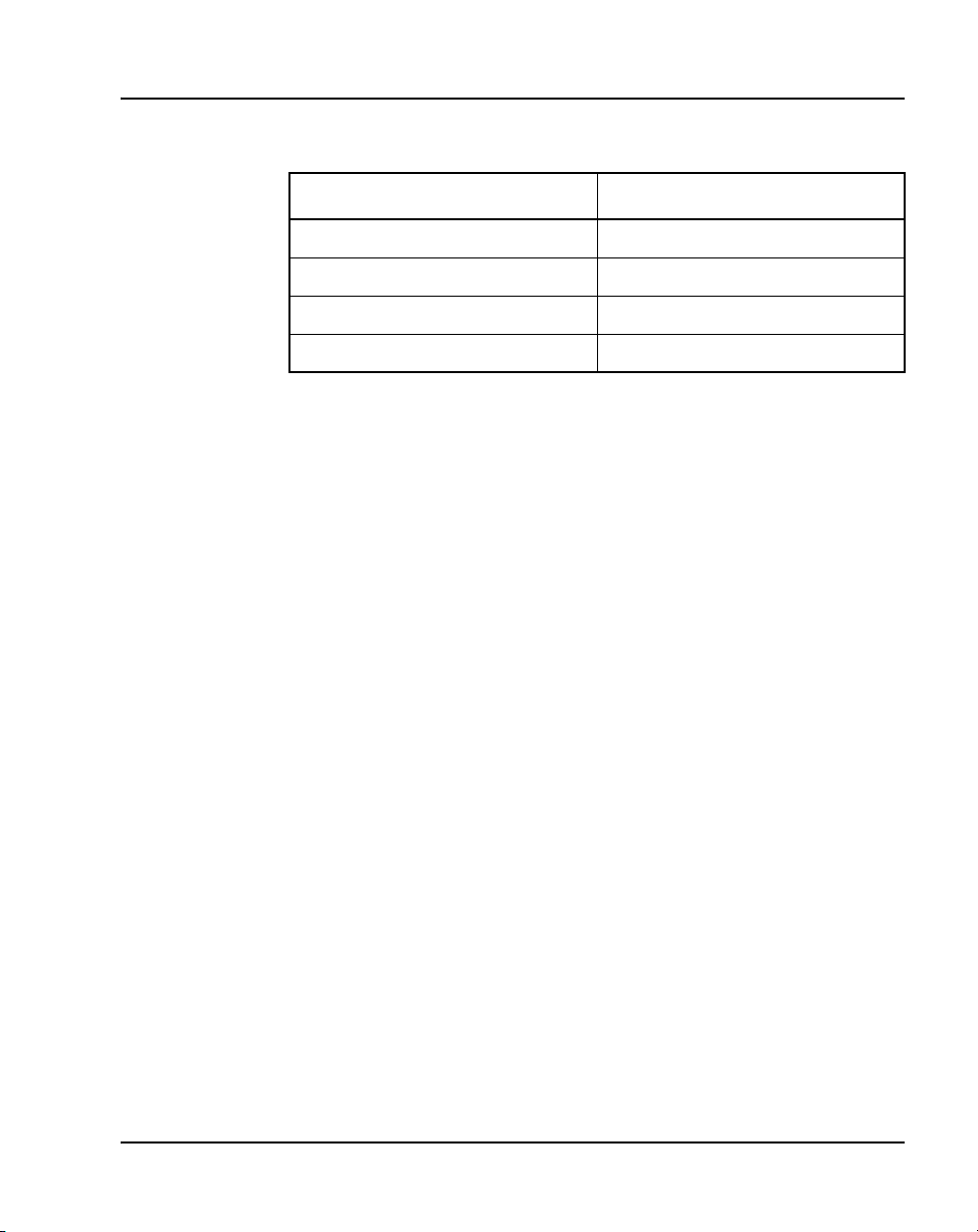
Table 1
Meridian 1 systems to CS 1000M systems (Part 2 of 2)
This Meridian 1 system... Maps to this CS 1000M system
Meridian 1 PBX 51C CS 1000M Half Group
Meridian 1 PBX 61C CS 1000M Single Group
Meridian 1 PBX 81 CS 1000M Multi Group
Meridian 1 PBX 81C CS 1000M Multi Group
For more information, see one or more of the following NTPs:
• Communication Server 1000M and Meridian 1: Small System Upgrade
Procedures (553-3011-258)
• Communication Server 1000M and Meridian 1: Large System Upgrade
Procedures (553-3021-258)
• Communication Server 1000S: Upgrade Procedures (553-3031-258)
• Communication Server 1000E: Upgrade Procedures (553-3041-258)
Intended audience
About this document Page 21 of 504
Conventions
This document is intended for individuals responsible for installing,
configuring, operating, administering, and troubleshooting Meridian
proprietary telephones, attendant consoles and add-on modules, and
engineering and configuring digital telephone lines.
Terminology
In this document, the following systems are referred to generically as
“system”:
• Communication Server 1000S (CS 1000S)
• Communication Server 1000M (CS 1000M)
Telephones and Consoles Description, Installation, and Operation
Page 22

Page 22 of 504 About this document
• Communication Server 1000E (CS 1000E)
•Meridian1
The following systems are referred to generically as “Small System”:
• Communication Server 1000M Chassis (CS 1000M Chassis)
• Communication Server 1000M Cabinet (CS 1000M Cabinet)
• Meridian 1 PBX 11C Chassis
• Meridian 1 PBX 11C Cabinet
The following systems are referred to generically as “Large System”:
• Communication Server 1000M Half Group (CS 1000M HG)
• Communication Server 1000M Single Group (CS 1000M SG)
• Communication Server 1000M Multi Group (CS 1000M MG)
• Meridian 1 PBX 51C
• Meridian 1 PBX 61C
•Meridian1 PBX81
• Meridian 1 PBX 81C
Related information
This section lists information sources that relate to this document.
NTPs
The following NTPs are referenced in this document:
• Spares Planning (553-3001-153)
• Equipment Identification (553-3001-154)
• Circuit Card: Description and Installation (553-3001-211)
• Features and Services (553-3001-306)
• Software Input/Output: Administration (553-3001-311)
• Attendant PC: Description, Installation, and Operation (553-3001-320)
553-3001-367 Standard 3.00 August 2005
Page 23

About this document Page 23 of 504
• Software Input/Output: System Messages (553-3001-411)
• Software Input/Output: Maintenance (553-3001-511)
• Communication Server 1000M and Meridian 1: Small System Upgrade
Procedures (553-3011-258)
• Communication Server 1000M and Meridian 1: Large System Upgrade
Procedures (553-3021-258)
• Analog Terminal Adapter Quick Reference Card
• PC Console Interface Unit Installation Guide
• PC Console Interface Unit Quick Reference Guide
• Installing the Analog Terminal Adapter
• Meridian Digital Telephones: M3901, M3902, M3903, M3904 User
Guide
• Meridian Digital Telephones: M3902, M3903, M3904 Quick Reference
Guide
• Meridian Digital Telephone: M3905 Call Center User Guide
• Nortel M2016S Secure Set Quick Reference Guide
• Nortel M2016S Secure Set User Guide
For information on IP Phones, refer to IP Phones: Description, Installation,
and Operation (553-3001-368).
Online
To access Nortel documentation online, click the Technical Documentation
link under Support on the Nortel home page:
http://www.nortel.com
CD-ROM
To obtain Nortel documentation on CD-ROM, contact your Nortel customer
representative.
Telephones and Consoles Description, Installation, and Operation
Page 24

Page 24 of 504 About this document
How to get Help
Getting Help from the Nortel Web site
The best source of support for Nortel products is the Nortel Support Web site:
www.nortel.com/support
This site enables customers to:
• download software and related tools
• download technical documents, release notes, and product bulletins
• sign up for automatic notification of new software and documentation
• search the Support Web site and Nortel Knowledge Base
• open and manage technical support cases
Getting Help over the phone from a Nortel Solutions Center
If you have a Nortel support contract and cannot find the information you
require on the Nortel Support Web site, you can get help over the phone from
a Nortel Solutions Center.
In North America, call 1-800-4NORTEL (1-800-466-7865).
Outside North America, go to the Web site below and look up the phone
number that applies in your region:
www.nortel.com/callus
When you speak to the phone agent, you can reference an Express Routing
Code (ERC) to more quickly route your call to the appropriate
support specialist. To locate the ERC for your product or service, go to:
www.nortel.com/erc
553-3001-367 Standard 3.00 August 2005
Page 25

About this document Page 25 of 504
Getting Help through a Nortel distributor or reseller
If you purchased a service contract for your Nortel product from a distributor
or authorized reseller, you can contact the technical support staff for that
distributor or reseller.
Telephones and Consoles Description, Installation, and Operation
Page 26

Page 26 of 504 About this document
553-3001-367 Standard 3.00 August 2005
Page 27

102
Page 27 of 504
Attendant consoles
Contents
This section contains information on the following topics:
Introduction . . . . . . . . . . . . . . . . . . . . . . . . . . . . . . . . . . . . . . . . . . . . . . 28
Engineering codes . . . . . . . . . . . . . . . . . . . . . . . . . . . . . . . . . . . . . . . . . 29
Features . . . . . . . . . . . . . . . . . . . . . . . . . . . . . . . . . . . . . . . . . . . . . . . . . 31
Busy Lamp Field/Console Graphics Module . . . . . . . . . . . . . . . . . . 32
Display backlight power supply option . . . . . . . . . . . . . . . . . . . . . . 44
DSS-9000 Direct Station Select/Busy Lamp Field . . . . . . . . . . . . . 44
Attendant Supervisory Module. . . . . . . . . . . . . . . . . . . . . . . . . . . . . 44
Physical description. . . . . . . . . . . . . . . . . . . . . . . . . . . . . . . . . . . . . . . . 48
Dimensions . . . . . . . . . . . . . . . . . . . . . . . . . . . . . . . . . . . . . . . . . . . . 48
Keyboard layout . . . . . . . . . . . . . . . . . . . . . . . . . . . . . . . . . . . . . . . . 51
Display screen messages . . . . . . . . . . . . . . . . . . . . . . . . . . . . . . . . . 55
Display screen messages . . . . . . . . . . . . . . . . . . . . . . . . . . . . . . . . . 55
Connections . . . . . . . . . . . . . . . . . . . . . . . . . . . . . . . . . . . . . . . . . . . 56
Local console controls . . . . . . . . . . . . . . . . . . . . . . . . . . . . . . . . . . . 56
Wiring . . . . . . . . . . . . . . . . . . . . . . . . . . . . . . . . . . . . . . . . . . . . . . . . . . 57
Installing wiring . . . . . . . . . . . . . . . . . . . . . . . . . . . . . . . . . . . . . . . . 57
Installation. . . . . . . . . . . . . . . . . . . . . . . . . . . . . . . . . . . . . . . . . . . . . . . 59
Normal operating ranges . . . . . . . . . . . . . . . . . . . . . . . . . . . . . . . . . 59
Packing and unpacking. . . . . . . . . . . . . . . . . . . . . . . . . . . . . . . . . . . 59
Installation and removal . . . . . . . . . . . . . . . . . . . . . . . . . . . . . . . . . . 60
Installing the M2250 attendant console . . . . . . . . . . . . . . . . . . . . . . 60
Removing the M2250 attendant console . . . . . . . . . . . . . . . . . . . . . 61
Telephones and Consoles Description, Installation, and Operation
Page 28

Page 28 of 504 Attendant consoles
Removing the M2250 attendant console top cover . . . . . . . . . . . . . 62
Installing the M2250 attendant console top cover . . . . . . . . . . . . . . 63
Performing a loopback test . . . . . . . . . . . . . . . . . . . . . . . . . . . . . . . 64
Designating keys on the M2250 attendant console . . . . . . . . . . . . . 64
Cross-connecting attendant consoles . . . . . . . . . . . . . . . . . . . . . . . . 68
Operation . . . . . . . . . . . . . . . . . . . . . . . . . . . . . . . . . . . . . . . . . . . . . . . 77
M2250 configurations . . . . . . . . . . . . . . . . . . . . . . . . . . . . . . . . . . . 77
Attendant PC requirements . . . . . . . . . . . . . . . . . . . . . . . . . . . . . . . 78
M2250 feature key modes . . . . . . . . . . . . . . . . . . . . . . . . . . . . . . . . 79
M2250 console diagnostics . . . . . . . . . . . . . . . . . . . . . . . . . . . . . . . 81
M2250 failure codes. . . . . . . . . . . . . . . . . . . . . . . . . . . . . . . . . . . . . 87
M2250 feature operation . . . . . . . . . . . . . . . . . . . . . . . . . . . . . . . . . 89
Introduction
Attendant consoles are designed to assist in placing and extending calls into
and out of a telephone switching system. The console is operated by an
attendant who is the human interface between the system and the users.
The M2250 attendant console is a stand-alone, digital attendant console
designed for telephone traffic control in the CS 1000 and Meridian 1. A
Digital Line Card (DLC) connects the M2250 to the system.
The PC-based Console application software allows all functions supported by
the M2250 to be performed on a computer workstation within a Windows
95®, Windows 98®, Windows 2000®, or Windows NT® operating system
environment. The PC-based Console application operates with the PC
Console Interface Unit (PCCIU). The PCCIU is typically installed under the
attendant’s PC monitor, and provides connection to the Main Distribution
Frame (MDF) and PC communications port. The PCCIU is configured as an
M2250 attendant console in LD 12. Refer to Software Input/Output:
Administration (553-3001-311) for configuration information
In the North America, Asia Pacific and CALA market regions, the PCCIU
and the Attendant PC software are available as a bundled package. In the
EMEA market region, the PCCIU is available on its own or with a separate
PC software application called SMILE.
553-3001-367 Standard 3.00 August 2005
Page 29

Attendant consoles Page 29 of 504
For more information on Attendant PC and the PCCIU, refer to the following
documents:
• Attendant PC: Description, Installation, and Operation (553-3001-320)
• PC Console Interface Unit Installation Guide
• PC Console Interface Unit Quick Reference Guide
Engineering codes
Refer to Table 2 for engineering codes for available M2250 attendant console
models and related equipment. For ordering information, refer to Equipment
Identification (553-3001-154). For EMEA codes, please contact your local
Nortel representative.
Table 2
Engineering codes for the M2250 and related equipment (Part 1 of 3)
Engineering
code
NT3G40BB-35 BLF/CGM Chameleon A0652760 CALA, Spain, US
Model Color Order code Availability
NT3G41BB-35 BLF/CGM Chameleon
Grey
NT3G41BB-98 BLF/CGM Dark Grey A0652759 APAC
NT3G42BA-35 BLF/CGM N/A A0642991 Africa, Australia,
NT3G42BA-93 BLF/CGM Dolphin A0656519 Australia, UK
Telephones and Consoles Description, Installation, and Operation
A0652758 APAC, Canada
Austria, Belgium, CIS,
Denmark, Europe,
Finland, France,
Germany, Greece,
Holland, Ireland,
Middle East, Norway,
Portugal, Sweden,
Switzerland, Turkey,
UK
Page 30

Page 30 of 504 Attendant consoles
Table 2
Engineering codes for the M2250 and related equipment (Part 2 of 3)
Engineering
code
NT3G42BA-98 BLF/CGM N/A A0642994 Finland, France,
Model Color Order code Availability
Germany
NT6G00AF-35 M2250 Chameleon
Grey
NT6G40BA-35 M2250 Chameleon
Grey
NT6G41BB-35 M2250 Chameleon
Grey
NT6G42BC-35 M2250 Chameleon
Grey
NT6G43BA-35 M2250 Chameleon
Grey
NT6G43BA-98 M2250 Dark Grey A0642790 Finland, Germany
NT6G44BA-35 M2250 Chameleon
Grey
NT6G45BA-35 M2250 Chameleon
Grey
NT6G47BB-35 M2250 Chameleon
Grey
A0393450 Africa, APAC, CALA,
CIS, Greece, Ireland,
Middle East, NA,
Portugal, Turkey
A0642786 Switzerland
A0642787 APAC, Norway
A0642788 Denmark
A0642789 Finland, Germany
A0642791 Austria
A0642792 Belgium
A0642793 France
NT6G47BB-98 M2250 Dark Grey A0642794 France
NT6G48BC-35 M2250 Chameleon A0642795 UK
NT6G48BC-93 M2250 Dolphin A0642796 New Zealand, UK
NT6G50BA-35 M2250 Chameleon A0642797 Australia
NT6G50BA-93 M2250 Dolphin A0642798 Australia
553-3001-367 Standard 3.00 August 2005
Page 31

Attendant consoles Page 31 of 504
Table 2
Engineering codes for the M2250 and related equipment (Part 3 of 3)
Engineering
code
NT6G53BB-35 M2250 Chameleon A0655900 Holland
Model Color Order code Availability
NT6G55BA-35 M2250 Chameleon
Grey
NT6G56BB-35 M2250 Chameleon
Grey
NT6G57BA-35 M2250 Chameleon
Grey
NT6G57BA-98 M2250 Dark Grey A0642804 Italy
NT3G30AA-35 Adjustable
stand
NT3G30AA-98 Adjustable
stand
NT7G10AA Attendant
Supervisory
Module (ASM)
Chameleon
gray (ash)
BTS dark gray A0348778 Global
N/A A0366221 Global
A0642799 Spain
A0642802 Sweden
A0642803 Italy
A0348780 Global
Features
The M2250 has the following features:
• A four-line, 40 character, liquid crystal display (LCD) with backlighting.
Power, including backlighting, is maintained during building power
failures with the system’s battery backup, if equipped.
• Angle adjustment of the display screen, which can be tilted through 90°
from horizontal to fully vertical.
• Scrolling control of lines 2 and 3 of the display screen.
• In Shift mode, the M2250 can have up to 20 Trunk Group Busy (TGB)
keys.
Telephones and Consoles Description, Installation, and Operation
Page 32

Page 32 of 504 Attendant consoles
• In Shift mode, the M2250 can have up to 10 extra flexible feature keys
for a total of 20.
• An optional supporting stand that can be adjusted to nine different
positions.
• A handset and headset volume slider control, situated below the dial pad.
• A physical connection to a serial data port through a subminiature D-type
female connector on the console back wall. This permits connection of
the console to the serial port of a personal computer.
• An optional Busy Lamp Field/Console Graphics Module (BLF/CGM),
which displays the status of up to 150 consecutive extensions (SBLF) or
any group of 100 extensions within the system (EBLF) and has many text
and graphics capabilities.
• An optional Attendant Supervisory Module (ASM) can be installed.
• Supports transmission level adjustment to meet international
requirements by accepting and processing downloaded information from
the system (when this messaging is supported in software). The
transmission level can be adjusted to one of 16 different levels.
• Multi-language selection.
• Menus for local console features (Options menu) and diagnostics
(Diagnostics menu).
• Code blue or emergency relay (associated with ICI 0).
• Time and date system download.
• Alert tone volume and frequency selection.
• Electret or carbon transmitter support.
• Power Fail Transfer switch.
• Keyclick.
Busy Lamp Field/Console Graphics Module
The Busy Lamp Field/Console Graphics Module (BLF/CGM) can be added
to an M2250 attendant console.
553-3001-367 Standard 3.00 August 2005
Page 33

Attendant consoles Page 33 of 504
The BLF/CGM can do the following:
• display the status (busy or idle) of up to 150 consecutive extensions
within the system Standard Busy Lamp Field (SBLF)
• display the status (busy or idle) of any hundred group of DNs within the
system Enhanced Busy Lamp Field (EBLF)
• display which attendant console is the supervisory console and which
consoles are active
• display supplementary information about individual extensions, such as
the reason the person is away (business, vacation, or illness), when the
person is due to return, and an alternate extension where calls to the
person should be directed
• display a company logo
• display graphics
• display text in any one of eight languages
• have its screen contrast adjusted for easy viewing
Power requirements
The BLF/CGM obtains its power through the attendant console. See Figure 1
on page 35. The requirements are as follows:
• a reference ground line (0 V)
• power source of 5 V for the CMOS electronics that control the Lamp
Field Array module (c. 50 mA)
• power source of –12 V for the display of the Console Graphics Module
(c. 10 mA)
• backlighting power
The BLF/CGM has a battery that provides backup power to maintain the
Supplementary Information when the console is powered down. The battery
lifetime is five years. To replace the battery, return the BLF/CGM to the
supplier.
Telephones and Consoles Description, Installation, and Operation
Page 34

Page 34 of 504 Attendant consoles
Installation
The BLF/CGM mounts on the back of the attendant console and is held on by
snap-fits and screws. It is connected to the console using a 16-way connector
that is located on the keyboard Printed Circuit Board (PCB). This connector
is accessed through a rectangular knockout section located underneath the
casing overhang at the Meridian logo location. The attendant console’s top
cover must be removed to install the BLF/CGM.
Refer to the following procedures to install the BLF/CGM:
• Procedure 1, “Connecting the BLF/CGM to the M2250 attendant
console”, on page 35
• Procedure 2, “Checking the functionality of the Busy Lamp Field/
Console Graphics Module”, on page 42
• Procedure 3, “Removing the Busy Lamp Field/Console Graphics
Module”, on page 43
Refer to the M1250/M2250 Attendant Console User Guide or the Busy Lamp
Field/Console Graphics Module User Guide for further information.
CAUTION WITH ESDS DEVICES
Follow normal antistatic precautions when installing the
BLF/CGM on the attendant console.
553-3001-367 Standard 3.00 August 2005
Page 35
Attendant consoles Page 35 of 504
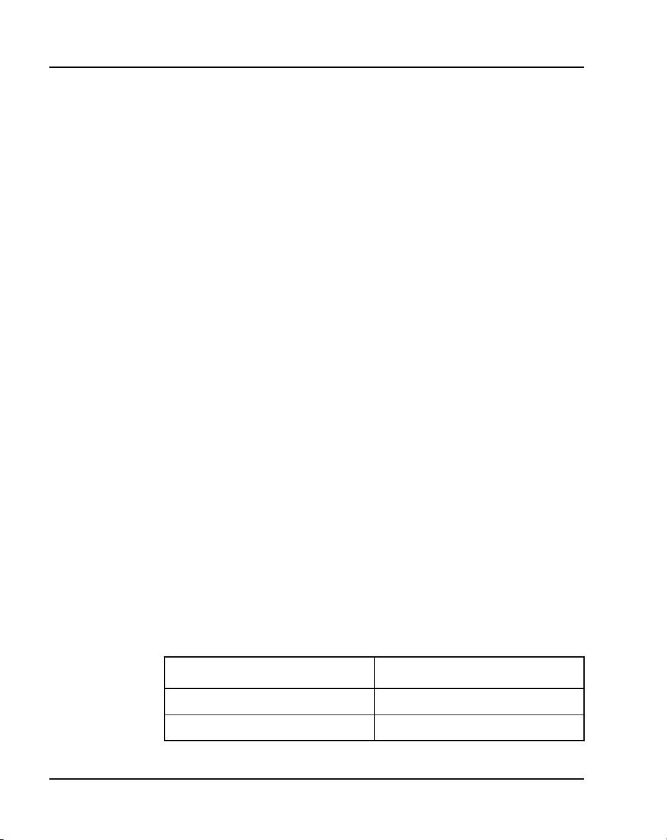
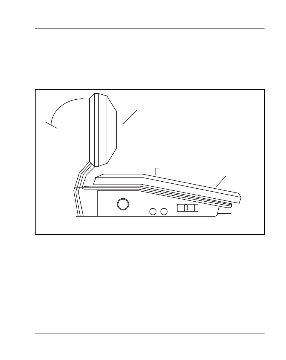
Figure 1
Busy Lamp Field/Console Graphics Module on the M2250 attendant console
BLF/CGM
M2250 Attendant Console
553-AAA1718.EPS
Procedure 1
Connecting the BLF/CGM to the
M2250 attendant console
1 Disconnect the main power/system cable from the rear of the attendant
console, and remove the handset jack plug from the side.
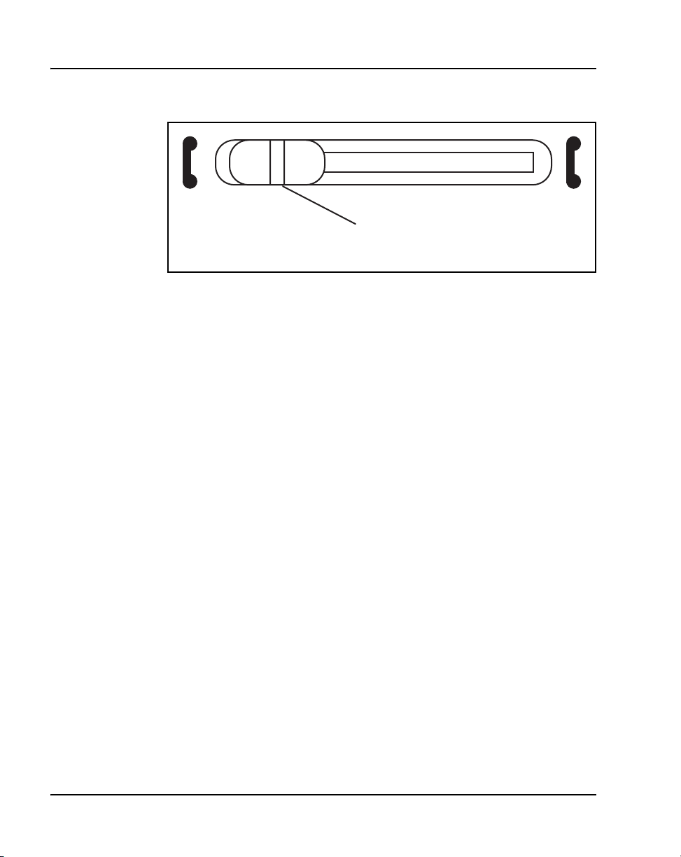
2 Move the adjustable display to the down position to protect it from
damage while installing the BLF/CGM. Move the volume slider switch to
the far left. See Figure 2 on page 36.
Telephones and Consoles Description, Installation, and Operation
Page 36
Page 36 of 504 Attendant consoles
Figure 2
Volume slider position
3 Place the attendant console facedown on a properly prepared work
surface, taking care to avoid scratching or damaging the top cover or
display. Remove the adjustable stand, if required.
The stand is secured with four screws. Remove the stand as a complete
assembly, and set aside.
4 Remove the 12 fastening screws in the base of the attendant console that
secure the top cover to the console base. See Figure 3 on page 37.
Holding the console base and cover firmly, turn it over so that the top
cover is on, facing up.
Move Volume Slider
to left-most position
553-AAA0626
553-3001-367 Standard 3.00 August 2005
Page 37
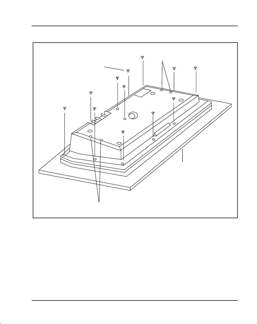
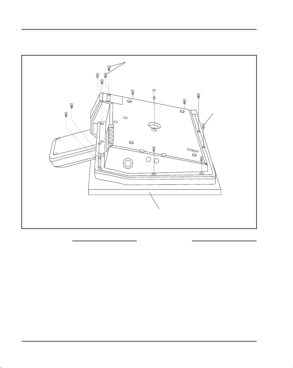
Figure 3
Removing the fastening screws
Remove These
12 Screws
Attendant consoles Page 37 of 504
Do Not Remove
These Screws
Polystyrene
Foam Sheet
Do Not Remove
These Screws
553-AAA0627
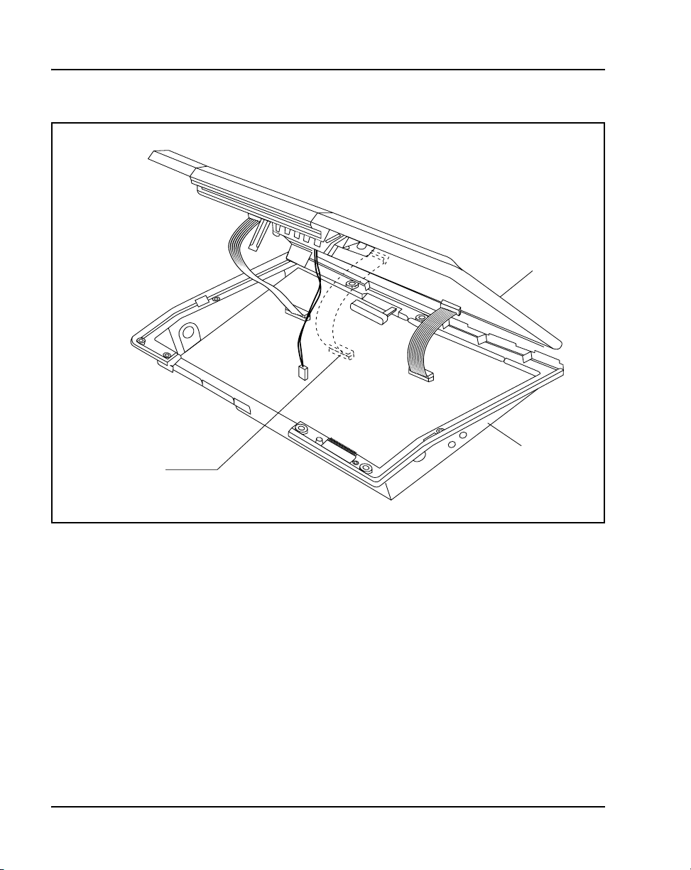
5 Raise and hold the top cover to remove the single cable connector only.
The alerter cable does not need to be removed. See Figure 4 on page 38.
6 Remove the top cover, and place it upside down to the left of the attendant
console.
Telephones and Consoles Description, Installation, and Operation
Page 38
Page 38 of 504 Attendant consoles
Figure 4
Removing the top cover
Remove flat cable
Top cover
Base
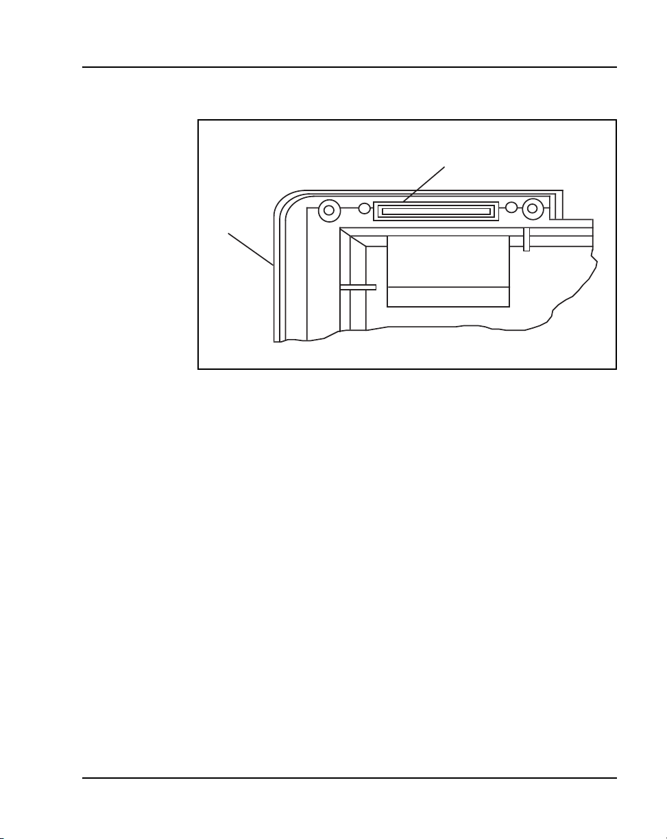
7 Remove the knockout section on the back of the attendant console (see
Figure 5 on page 39) with a small screwdriver or similar tool. Remove any
remnants of the breakaway tags.
8 Feed the flat ribbon cable for the Busy Lamp Field/Console Graphics
Module (BLF/CGM) through the knockout hole in the base of the
attendant console.
9 Hold the BLF/CGM unit over the console in a vertical position, ensuring
that the two locators on the bottom bracket of the BLF/CGM are located
in the knockout hole.
553-3001-367 Standard 3.00 August 2005
553-AAA1719.EPS
Page 39
Attendant consoles Page 39 of 504
Figure 5
Attendant console knockout section
Knockout Section
(Clean Away 6 Tags)
Base
553-AAA0629
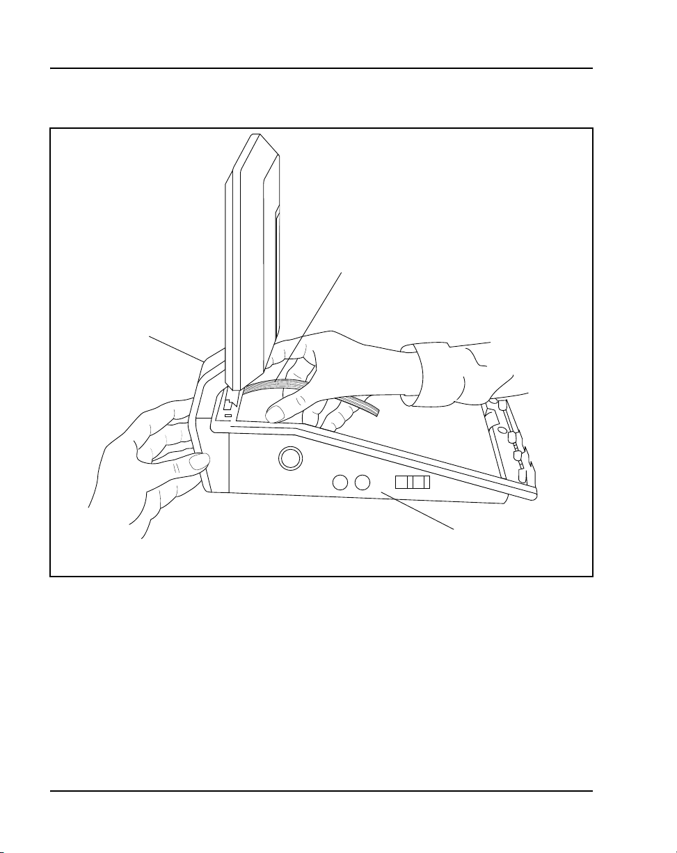
10 Push down on the attendant console, while holding the BLF/CGM unit,
until the two locators snap into place. See Figure 6 on page 40.
11 Fit the BLF/CGM ribbon cable onto the top cover circuit board, into the
flexible strip connector J4 (so that the blue line on the cable faces away
from the circuit board).
12 Hold the top cover over the attendant console and reconnect the cable
connector(s) onto the base of the attendant console.
13 Place the top cover on the console. Slide it back and down into place. See
Figure 7 on page 41. Check that all the cables are in the correct positions
and that none are trapped.
14 Push the BLF/CGM display into position by rotating it back (see Figure 7).
15 Ensuring that the volume slider is fully engaged in the correct slider, hold
the top cover and console base firmly together. Turn the assembly upside
down. See Figure 8 on page 42.
16 Reinsert the 12 screws that secure the top cover to the console base and
tighten.
17 Insert the two new screws supplied with the BLF/CGM that attach it to the
base, and tighten. See Figure 8 on page 42.
Telephones and Consoles Description, Installation, and Operation
Page 40
Page 40 of 504 Attendant consoles
Figure 6
Connecting the BLF/CGM to the attendant console
BLF/CGM
BLF/CGM Flat cable
18 Cable in BLF power at the local Main Distribution Frame (MDF) as per
M2250 cross-connections.
19 If required, replace the adjustable stand.
20 Reconnect the main system cable to the rear of the console.
21 If the BLF/CGM has been correctly installed, the main menu appears
when power is supplied to the attendant console. Test the BLF/CGM by
selecting a menu option. Refer to Busy Lamp Field/Console Graphics
Module User Guide for programming information.
553-3001-367 Standard 3.00 August 2005
Base
553-AAA0630
Page 41
22 Define the Busy Lamp Field in the system database. Refer to Features
and Services (553-3001-306).
23 Test the Busy Lamp Field features using M1250/M2250 Attendant
Console User Guide.
Figure 7
Positioning the top cover and the BLF/CGM
BLF/CGM
Rotate Back
Attendant consoles Page 41 of 504
Slide Back
and Down
Top Cover
Base
553-AAA0632
Telephones and Consoles Description, Installation, and Operation
Page 42
Page 42 of 504 Attendant consoles
Figure 8
Attaching the top cover to the attendant console base and BLF/CGM
Fit 2 new screws
Re-Insert
12 Screws
Procedure 2
Checking the functionality of the
Busy Lamp Field/Console Graphics Module
Use this procedure to check the functionality of the BLF/CGM. Once in this
menu, the dial pad is in CGM mode. When any dial pad keys are pressed,
except the pound (#) key, the keys are echoed on the BLF/CGM.
1 From Diagnostics menu 1, press 5.
2 Press keys 0 through 9 and the asterisk (*) on the dial pad. Check the
CGM to see that they are echoed.
553-3001-367 Standard 3.00 August 2005
Polystyrene foam sheet
553-AAA0633
End of Procedure
Page 43

Attendant consoles Page 43 of 504
3 Press the pound (#) to exit and return to Diagnostics menu 1.
End of Procedure
Procedure 3
Removing the Busy Lamp
Field/Console Graphics Module
1 Disconnect the main power/system cable from the rear of the attendant
console, and remove the handset jack plug from the side.
2 Move the adjustable display to the down position to protect it from
damage while removing the BLF/CGM. Also move the volume slider
switch to the far left (see Figure 2 on page 36).
3 Place the attendant console facedown on a properly prepared work
surface, taking care to avoid scratching or damaging the top cover or
display. Remove the adjustable stand, if required.
The stand is secured with four screws. Remove the stand as a
complete assembly, and set it aside.
4 Remove the 12 fastening screws in the base of the attendant console that
secure the top cover to the console base. See Figure 3 on page 37.
Remove the two screws securing the BLF/CGM to the base of the
attendant console.
5 Holding the console base and cover firmly, turn it back over so that the top
cover is on, facing up.
6 Raise and hold the top cover to remove the single cable connector only.
The alerter cable does not need to be removed (see Figure 4 on page 38).
7 Unplug the BLF/CGM ribbon cable from the attendant console.
8 Remove the top cover and place it upside down to the left of the attendant
console.
9 Pull back the snap-fits on the BLF/CGM to disengage the BLF/CGM from
the attendant console.
10 Place the top cover on the console. Slide it back and down into place (see
Figure 7 on page 41). Reconnect all cables in the correct positions, and
make sure that none are trapped.
Telephones and Consoles Description, Installation, and Operation
Page 44

Page 44 of 504 Attendant consoles
11 Ensuring that the volume slider is fully engaged in the correct slider, hold
the top cover and console base firmly together. Turn the assembly upside
down (see Figure 8 page 42).
12 Reinsert the 12 screws that secure the top cover to the console base and
tighten.
13 If required, replace the adjustable stand.
14 Reconnect the main system cable to the rear of the console.
For more on the features and operation of the BLF/CGM, refer to the Busy
Lamp Field/Console Graphics Module User Guide.
Display backlight power supply option
An optional 16 V DC power supply (A0367601) can be installed to the Main
Distribution Frame (MDF) to improve the backlight brightness of the BLF/
CGM display.
The display backlight power supply must be cabled in at the local MDF at a
maximum of 120 ft (36 m) from the attendant console when the BLF/CGM is
installed (A0367601 – Transformer). This provides all the power
requirements for the M2250 applications.
End of Procedure
DSS-9000 Direct Station Select/Busy Lamp Field
The DSS-9000 is a combined 150-lamp busy field and 150-button direct
station select console that can be attached to an M2250 attendant console. The
DSS-9000 emulates either a QMT-3 Busy Lamp Field array (standard Busy
Lamp Field mode) or the Enhanced Busy Lamp Field Mode of a Console
Graphics Module. For more information on DSS-9000 Direct Station Select/
Busy Lamp Field, refer to the DSS-9000 Direct Station Select/Busy Lamp
Field User Guide.
Attendant Supervisory Module
A customer may wish to supervise an attendant console. To allow the M2250
to be supervised, an Attendant Supervisory Module (ASM) must be added.
553-3001-367 Standard 3.00 August 2005
Page 45
Attendant consoles Page 45 of 504
An attendant console configured as a supervisor does not need the ASM
installed.
To accept the ASM, the minimum vintage M2250 attendant console is
M2250AD. To fully support the ASM, the minimum vintage BLF/CGM is
AB. The third PWR TN must be programmed and wired out to support the
ASM. See Figure 17 on page 71.
Follow the steps in Procedure 4 to install an ASM on an M2250 attendant
console.
Procedure 4
Installing an Attendant Supervisory Module
on an M2250 attendant console
CAUTION WITH ESDS DEVICES
Damage to Equipment
Before handling internal set components, discharge
static electricity from hands and tools by touching
any grounded metal surface or conductor
1 Disconnect the main power/system cable from the rear of the attendant
console, and remove the handset jack plug from the side.
.
2 Move the adjustable display to the down position to protect it from
damage while installing the ASM. Move the volume slider switch to the
left-most position.
3 Place the attendant console facedown on a properly prepared work
surface, taking care to avoid scratching or damaging the top cover or
display. Remove the adjustable stand, if equipped.
The stand is secured with four screws. Loosen the screws and remove
the stand as a complete assembly, and set aside.
4 Remove the 12 fastening screws in the base of the attendant console that
secure the top cover to the console base (see Figure 3 on page 37).
Holding the console base and cover firmly, turn it back over so that the top
cover is on, facing up.
Telephones and Consoles Description, Installation, and Operation
Page 46
Page 46 of 504 Attendant consoles
5 Raise and hold the top cover to remove the single cable connector. The
alerter cable does not need to be removed (see Figure 4 on page 38).
Remove the top cover and place it upside down to the left of the attendant
console.
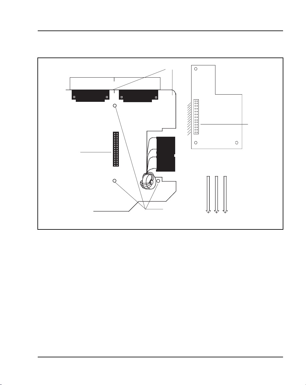
6 Holes are located in the upper right-hand side of the attendant console’s
main PCB, near grid positions D1, D5, and A5. See Figure 9 on page 47.
Insert one standoff in each of the holes, twisting it until it is secure.
7 Position the ASM board over the J3 connector on the console’s main
PCB. Align the holes on the ASM board with the standoffs, and carefully
work the ASM pin connector onto connector J3 until firmly seated. See
Figure 9 on page 47.
8 Hold the top cover over the attendant console, and reconnect the cable
connector onto the base of the console.
9 Place the top cover on the console. Slide it back and down into place.
Check that all the cables are in the correct positions, and that none are
trapped.
10 Ensure that the volume switch is fully engaged in the correct slider. Hold
the top cover and console base firmly together. Turn the assembly upside
down.
11 Reinsert the 12 screws that secure the top cover to the console base and
tighten.
12 If required, replace the adjustable stand.
13 Reconnect the main system cable to the rear of the console.
CAUTION
Damage to Equipment
Once a standoff is inserted, it cannot be removed. Be
sure to place each standoff in the correct hole on the
main PCB, as shown in Figure 9 on page 47.
14 Test the supervisory console feature to make sure you can now properly
supervise the M2250 attendant console. Refer to M1250/M2250
Attendant Console User Guide.
553-3001-367 Standard 3.00 August 2005
End of Procedure
Page 47
Attendant consoles Page 47 of 504
Figure 9
Identifying the correct grid positions on the main PCB and attaching the ASM
Grid marks
59
A
J3 connector
M2250 main PCB (cutaway)
B
C
Attendant Supervisory Module
D
Insert Standoffs here
Pin connector
553-AAA0634
Telephones and Consoles Description, Installation, and Operation
Page 48
Page 48 of 504 Attendant consoles
Physical description
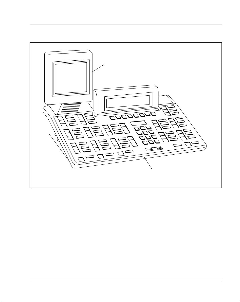
Figure 10 on page 49 shows a top view of the M2250 attendant console
layout. The user-accessible components are labeled using a row/column grid
arrangement. Figure 11 on page 50 shows rear, left side, and bottom views of
the console. These illustrations show where to find the various components.
Dimensions
Dimensions of the M2250 attendant console are as follows:
Table 1
Dimensions
Width 425 mm (16.75 in.)
Depth 245 mm (9.6 in.)
Height (front) 25 mm (1 in.)
Height (back) 65 mm (2.5 in.)
Height (with display screen panel up) 115 mm (4.5 in.)
Weight approximately 2.75 kg (6 lbs)
553-3001-367 Standard 3.00 August 2005
Page 49
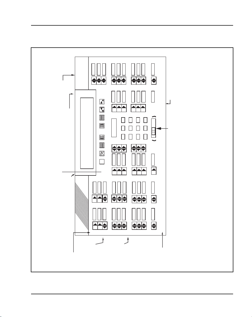
Figure 10
M2250 attendant console – top view
Attendant consoles Page 49 of 504
console to distributing frame
connector for cable connecting
25-pin subminiature D-type male
Display 2
Display 1
connection to PC with Monitor
RS-232 Connector for
or
Display line 4
Display line 3
Display line 2
Display line 1
B
A
C/H
F
EX.Scr
(8)
(7)
(6)
(5)
Directory Number
(4)
(3)
(2)
C
(1)
EX.Des
D2
D1
D0
RL.Src
3
2
1
6
5
4
RL.Des
Conf
9
8
7
Shift
FK
he
553-AAA0566
FI
ies keystrips.
EK
Hold
(in base of console)
Power Fail Transfer Switch
EI
#
0
*
DI/EI
CK
CI
BK
BI
Slider Control for Handset or Headset Volume Adjustments
AK
purposes only (not designated on the console)
Arbitrary Icon key numbering for test identification
Display screen (can be tilted upwards)
Rows
9
console)
(in both sidesof
headset jacks
Handset or
8
7
6
5
Slider Switch
ON/OFF
Backlighting
Telephones and Consoles Description, Installation, and Operation
AI
2
4
1
3
0
Rows and columns are labeled with numbers and letters respectively in order to allow textual references when identifying t
Columns
Note:
location of specific components. In the column designations, the letter I stands for indicators, and the letter K signif
Page 50
Page 50 of 504 Attendant consoles
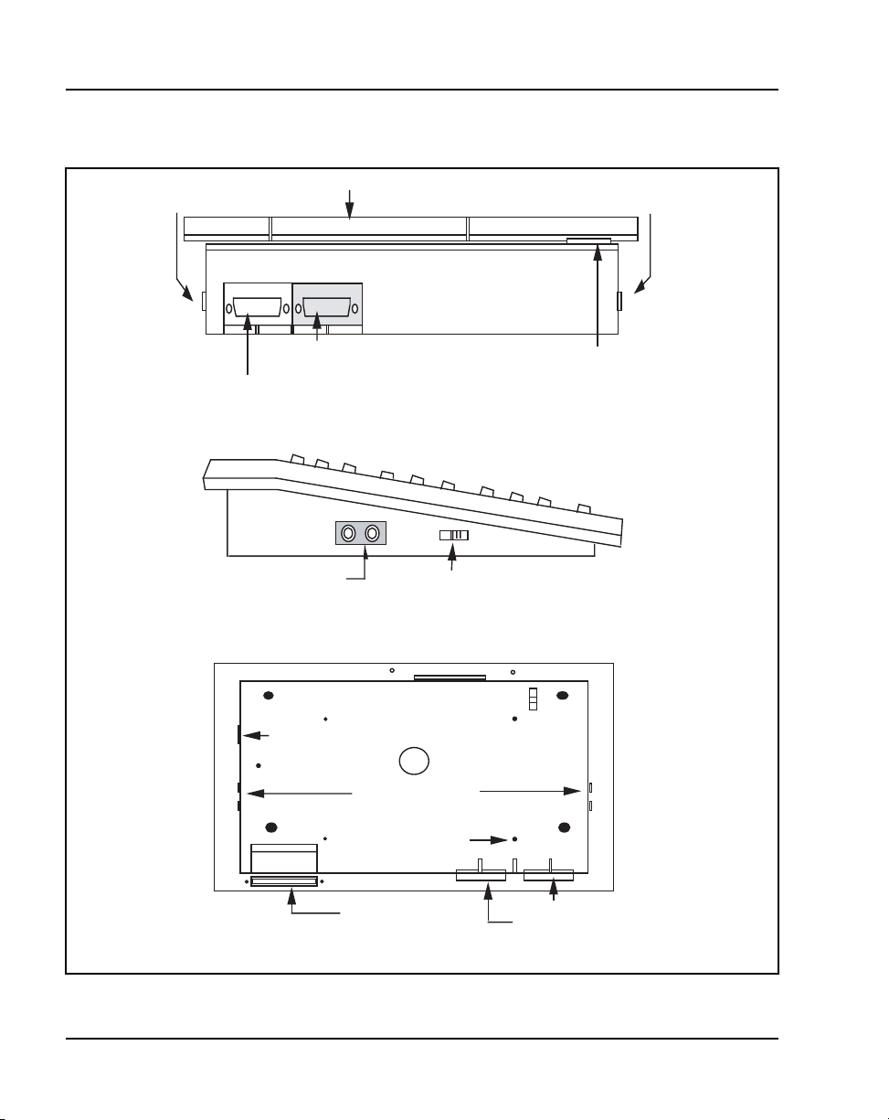
Figure 11
M2250 attendant console – rear, left side, and bottom views
Display panel (can be tilted upwards)
Handset/Headset jacks
Protective plastic cover to be installed when
........
.......
.......
.......
connector is not in use
Handset/Headset jacks
RS-232 female connector for connection
to PC with monitor (data port)
25-pin subminiature D-type male connector for cable
connecting console to distributing frame
Rear view
Handset/Headset jacks
(same on opposite side)
Backlighting ON/OFF slider switch
Left side view
Front edge of console
Power Fail Transfer
switch (PFT)
Off
On
Backlighting
slider switch
Handset/Headset jacks
Adjustable standscrew
mounting point (total of 4)
Knockout for access
to J4 connector
(BLF/CGM)
Knockout for access
to J4 connector
(BLF/CGM)
Bottom view
553-3001-367 Standard 3.00 August 2005
RS-232 female connector
25-pin D-type male connector
553-AAA0575
Page 51
Keyboard layout
Refer to Table 3 for the description of keys and Figure 10 on page 49 and
Figure 11 on page 50 for the location of switches and keys mentioned in this
section.
Function keys
The attendant console has eight function keys, located directly below the
display screen. Refer to Table 3 for the positions, functions, and markings of
these keys. For an explanation of the functions assigned to the other attendant
console keys, refer to “Operation” on page 77.
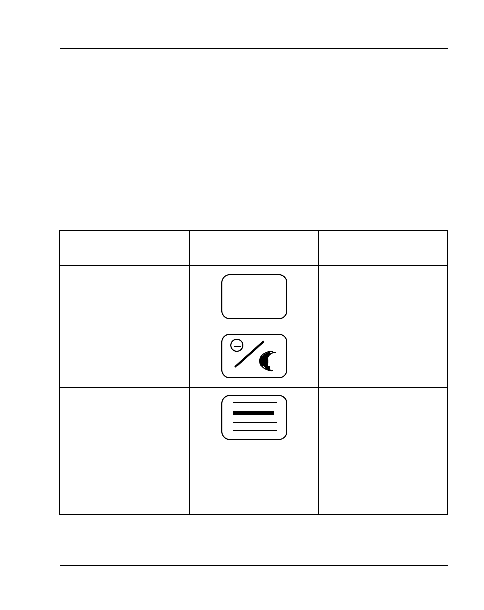
Table 3
Softkey definitions and functions (Part 1 of 3)
Key number
(see Figure 10)
Symbol Function
Attendant consoles Page 51 of 504
(1)
(2)
(3)
Centralized Attendant Service
(CAS) File
C/H
Prime function (normal):
Position Busy feature
Level 1 function (Shift):
Night Service feature
Prime function (normal):
Selects display screen line 2 for
scrolling.
Level 1 function (Shift):
Selects the Options menu on the
display screen.
Alternating between the idle and
active call display. From the idle
display, press this key to show
the active call display.
Telephones and Consoles Description, Installation, and Operation
Page 52
Page 52 of 504 Attendant consoles
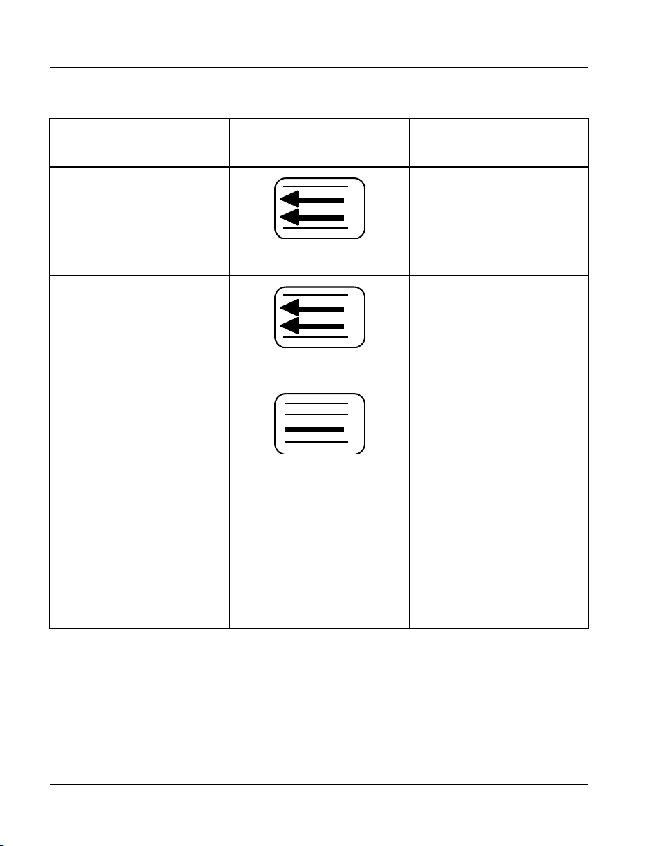
Table 3
Softkey definitions and functions (Part 2 of 3)
Key number
(see Figure 10)
Symbol Function
(4)
(5)
(6)
Prime function (normal):
Scrolls the currently selected line
to the left.
Level 1 function (Shift):
Decreases the alert speaker
volume.
Prime function (normal):
Scrolls the currently selected line
to the right.
Level 1 function (Shift):
Increases the alert speaker
volume.
Prime function (normal):
Selects line 3 on display screen
for scrolling.
Level 1 function (Shift):
Selects the Diagnostics menu on
the display screen. The
Diagnostics menu is
password-protected. To display
it, the user must enter a 4-digit
password and press * on the dial
pad.
Alternating between the idle and
active call display. From the
active call display, press this key
to show the idle display.
553-3001-367 Standard 3.00 August 2005
Page 53
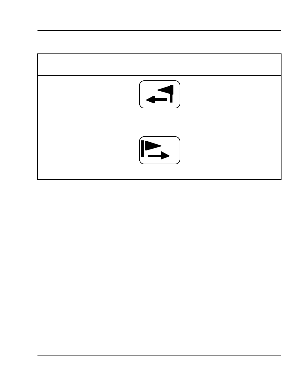
Table 3
Softkey definitions and functions (Part 3 of 3)
Key number
(see Figure 10)
Symbol Function
Attendant consoles Page 53 of 504
(7)
(8)
Prime function (normal):
Signal Source feature key
Level 1 function (Shift and Conf/
Busy Lamp Field key):
Used with the Busy Lamp Field/
Console Graphics Module, as
CGM key.
Prime function (normal):
Signal Destination feature key
Level 1 function (Shift):
Used with the Busy Lamp Field/
Console Graphics Module, as the
Mode key.
Switches
A slider control, located below the dial pad, between columns DI/EI and FI,
controls the handset and headset receive volume level. See Figure 10 on
page 49.
A Power Fail Transfer (PFT) switch is located in the baseplate. See Figure 11
on page 50. Both the line connector and the RS-232 connector for the PC port
are located at the back of the console.
Shift key
The Shift key is positioned in column FK, row 1, just above the Hold key. See
Figure 10 onpage 49. It is used to access Level 1 mode functions.
Handset and headset jacks
Two pairs of jacks are provided for plugging in handsets or headsets. The
jacks are located on both sides of the console beneath the faceplate in the
recessed area shown by the arrows. See Figure 10 on page 49. The console
Telephones and Consoles Description, Installation, and Operation
Page 54

Page 54 of 504 Attendant consoles
accepts both carbon and electret handsets or headsets and automatically
adapts itself to each type.
Note: Electret headsets and handsets are polarity sensitive and must be
correctly inserted into the jack.
LCD indicators
The LCD indicators on the M2250 display triangular symbols that normally
point towards the key with which they are associated. Certain keys in the
QMT2 mode of operation and loop keys have two LCDs associated with each
key instead of one.
Every LCD can flash at 30, 60, or 120 impulses per minute (ipm). Refer to
“Operation” on page 77 for more details.
The M2250 attendant console has 10 additional flexible features. These are
programmed in LD 12 and accessed using the Shift key.
553-3001-367 Standard 3.00 August 2005
Page 55

Display screen messages
Source information appears on line 2 of the display screen. Destination
information appears on line 3 of the display screen.
The status messages listed below appear on line 4 of the display screen panel.
— MN (minor alarm)
— MJ (major alarm)
— C/H (CAS/History File)
— CW (Call Waiting)
— BUSY (Position Busy)
— NIGHT (Night Service)
—IDLE (Idle)
— ACTIVE (lpk has been selected)
— S (Shift mode)
— EMERGENCY (Power Fail Transfer (PFT) feature is activated.)
The first four status messages appear as MN, MJ, C/H, and CW on line 4 of
the display screen panel. BUSY and NIGHT are combined with the status of
the Release lamp to indicate the console status as shown in Table 4.
Attendant consoles Page 55 of 504
Table 4
Release lamp indicator status
Typ e Indicator Status
Display screen status (line 4)Night Busy Release
ON X X NIGHT
OFF ON X BUSY
OFF OFF ON IDLE
OFF OFF OFF ACTIVE
X X X EMERGENCY
Telephones and Consoles Description, Installation, and Operation
Page 56

Page 56 of 504 Attendant consoles
If the emergency power fail transfer feature is activated, the console status
will be displayed as EMERGENCY.
Connections
The line cord connects to the rear of the M2250 attendant console through a
25-pin subminiature D-type connector. The jack connector is attached to the
line cord for user safety and equipment protection (pins are not exposed).
Having the plug connector mounted in the console also prevents interchanges
between the line cord and the serial data port connectors (the serial data port
in the console has a jack connector).
Identical two-prong G3 type connectors are provided on each side of the
console body to permit handset or headset connection at either side of the
console. The M2250 attendant console is compatible with both carbon and
electret handsets or headsets. The electret handset plug is
orientation-dependent and is labeled accordingly.
The attendant console is connected to the system through two digital ports –
one port for Call Service processing and one for Call Destination
processing – with three additional ports for powering, for a total of five ports.
The PCCIU interface used for the PC-based Console software application
requires only three ports in total.
The attendant console requires a Digital Line Card (DLC) or an Integrated
Services Digital Line Card (ISDLC) NT8D02 or later.
Local console controls
Visual contrast on the display panel can be adjusted using the Contrast option
on the Options menu.
From the Options menu, four-line mode can be changed to two-line mode for
easier viewing and to use larger fonts.
The pitch and volume of the buzz tone on the console can be adjusted by
the user.
Any one of 15 languages can be chosen for the console screen displays:
English, French, Spanish, German, Italian, Norwegian, Irish (Gaeilge),
553-3001-367 Standard 3.00 August 2005
Page 57

Wiring
Attendant consoles Page 57 of 504
Turkish, Katakana, P.R.C. (People’s Republic of China), Taiwan, Korean,
Polish, Czech/Slovak, or Hungarian.
When the languages P.R.C., Taiwanese, and Korean are chosen, the attendant
console uses two-line display.
The attendant console is equipped with a real-time clock/calendar. The time
of day (hours, minutes, and seconds) and the date (day, month, and year) are
displayed on line 1 of the display screen.
The sound of key clicks can be turned on or off. The pitch and volume of key
clicks can be adjusted.
The M2250 attendant console requires a 16-pair cable terminated on an
Amphenol connector.
When zone cabling and conduit are used, assign a block of numbers or letters
to each zone. Allow for growth when assigning blocks of numbers.
Cable markers are normally an adhesive-backed cloth tape 1/2 inches wide by
3-1/2 inches long (15 mm by 65 mm) with preprinted numbers.
For limits and cabling for analog (500/2500-type) telephones, refer to
Figure 12 on page 58.
For a list of terminal connections, see Table 5 on page 59.
Installing wiring
Follow the steps in Procedure 5 to install the wiring for a telephone.
Procedure 5
Installing wiring
1 Assign a number to the wire or cable used.
2 Attach the assigned number to the wire or cable at the end nearest the
telephone, using a cable marker.
Telephones and Consoles Description, Installation, and Operation
Page 58

Page 58 of 504 Attendant consoles
3 Run the wire or cable between the telephone location and nearest
cross-connect point (if not previously run).
4 Connect the cable or wire to the telephone connecting block.
5 Designate the telephone connecting block.
Figure 12
Zone cabling and conduit assignment
Zone Zone Zone Zone
1.2
1
1.1
5
Zone Conduit
2.1
6
2.2
2
Apparatus
Closet
3
7
Each Zone is
approximately
600-800 feet
13 14 15 16
10
9
Satellite
11
Closet
4
8
12
17
6 Cross-connect the pairs at intermediate cross-connect points (if required)
and terminate at the cross-connect terminal.
553-3001-367 Standard 3.00 August 2005
18
19 20
553-AAA0579
Page 59

7 Terminate leads at the cross-connect terminal and designate the blocks
Table 5
Terminal connections
Attendant consoles Page 59 of 504
according to the house cable plan.
NE-47QA or
QBB1B
G 1T T1 (G) G W-BL
R 1R R1 (R) R BL-W
BK X1 AUX (BK) BK W-O
Y X2 GND (Y) Y O-W
5 R T2 (BL) W-SL
6 B R2 (W) SL-W
Normal operating ranges
Installation
Connecting block
Designations
NE-284-74-500
1 adapter
NE-625F
TELADAPT
plugs and jacks
Z station wire 16/25-pair cable
Inside wiring
Colors
The M2250 attendant console has a maximum permissible loop length of
3500 ft (915 m), assuming 24 AWG (0.5 mm) wire with no bridge taps. A
15.5 dB loss at 256 kHz defines the loop length limit.
This section provides installation instructions for the M2250 attendant
console. For Attendant PC Software installation instructions, refer to
Meridian 1 Attendant PC: Software Installation Guide.
Packing and unpacking
Use proper care while unpacking the M2250 attendant console. Check for
damaged containers so that appropriate claims can be made to the transport
company for items damaged in transit.
Telephones and Consoles Description, Installation, and Operation
Page 60

Page 60 of 504 Attendant consoles
If an attendant console must be returned to the factory, pack it in the
appropriate container to avoid damage during transit. Remember to include
all loose parts (cords, handset, power unit, labels, and lenses) in the shipment.
Installation and removal
Use the following procedures to install and remove M2250 attendant
consoles.
Note: Although M2250 attendant consoles do not require a static
discharge ground connection, the connection should be installed to
protect any earlier vintage attendant consoles that may be used as
replacements.
Choose a clean, level work surface and place several sheets of soft, clean
paper between the attendant console and the work surface. This will prevent
scratching or otherwise damaging the top cover, LCD indicators and screen,
and the feature keys of the attendant console.
Installing the M2250 attendant console
Follow the steps in Procedure 6 to install the M2250 attendant console.
Procedure 6
Installing the M2250 attendant console
1 Ensure that a 16-pair or 25-pair cable equipped with a 25-pair Amphenol
connector is installed at the attendant console’s location.
2 Unpack and inspect the attendant console for damage. If the console is
damaged, notify the supplier.
3 Designate the console according to the features provided.
4 Connect the Amphenol plug on the attendant console to the Amphenol
jack coming from the Main Distribution Frame (MDF).
a. Fasten the Amphenol connectors together and secure the captive
screws on the cable.
b. Ensure that the connectors are secured in a connector mounting, if
provided, or to the wall. Do not leave connectors unprotected on the
floor.
553-3001-367 Standard 3.00 August 2005
Page 61

Attendant consoles Page 61 of 504
5 Add a line circuit for the attendant console, if not already done. Refer to
Circuit Card: Description and Installation (553-3001-211).
6 Cross-connect the attendant console at the cross-connect terminal. See
Procedure 12 on page 69.
7 Enter the related attendant console data in the system. Refer to Software
Input/Output: Administration (553-3001-311).
8 Test the console features using the attendant console user guide.
Note: Refer to Circuit Card: Description and Installation (553-3001-211)
for circuit card installation procedures.
End of Procedure
Removing the M2250 attendant console
Follow the steps in Procedure 7 if it is necessary to remove an M2250
attendant console.
Procedure 7
Removing the M2250 attendant console
1 Remove related attendant console data from the system memory. Refer
to the Software Input/Output: Administration (553-3001-311).
2 Locate and remove cross-connections from the attendant console cable
at the cross-connect terminal. See Procedure 12 on page 69.
3 Remove the circuit card if required. Refer to Circuit Card: Description and
Installation (553-3001-211).
Note: Do not remove the circuit card if any of the remaining units on the
card are assigned.
4 Disconnect the Amphenol connector on the end of the cable leading to the
cross-connect terminal from the connector on the cable leading to the
attendant console.
5 Pack the attendant console, handset, and cords in a suitable container.
End of Procedure
Telephones and Consoles Description, Installation, and Operation
Page 62

Page 62 of 504 Attendant consoles
Removing the M2250 attendant console top cover
Follow the steps in Procedure 8 to remove the M2250 Attendant top cover.
Procedure 8
Removing the M2250 attendant console top cover
1 Disconnect any plugs and cords from the attendant console.
2 Remove the ten 10-mm fastening screws in the flange of the attendant
console, as well as one 10-mm and one 40-mm screw on the base of the
attendant console. See Figure 13 for the M2250 assembly drawing.
Figure 13
M2250 assembly drawing (exploded view)
Support screw
(1 of 10)
LCD screen
LCD screen
hinge assembly
Base housing
assembly
Ribbon cable
Faceplate
assembly
553-3001-367 Standard 3.00 August 2005
553-AAA0580
Page 63

Attendant consoles Page 63 of 504
3 Holding the top cover and the base together by hand, turn the attendant
console right-side up and place it back on the work surface.
4 Carefully lift the faceplate straight up and disconnect the 20-pin plug
ribbon cable located at J2.
Note: On attendant consoles with a display attached to the top cover, do
not connect or disconnect the cable to the display unless the attendant
console line cord is disconnected.
End of Procedure
Installing the M2250 attendant console top cover
Follow the steps in Procedure 9 to install the M2250 attendant console top
cover.
Procedure 9
Installing the M2250 attendant console top cover
1 Set the QMT2 dip switch. To locate the dip switch, look at the attendant
console from the top. The QMT2 dip switch is the only dip switch on the
topmost circuit board. Set the switch to ON (enable QMT2) or OFF
(disable QMT2).
Note: The QMT2 feature must be enabled in system software. Refer to
LD 12 in Software Input/Output: Administration (553-3001-311).
2 Carefully lift the top cover straight up and connect the 20-pin plug ribbon
cable to J2.
3 Put the top cover back on the attendant console:
a. Place the top cover onto the base housing, and turn the attendant
console upside down.
b. Reinsert and tighten the ten 10-mm fastening screws on the flange.
c. Reinsert and tighten one 10-mm and one 40-mm fastening screw on
the back.
4 Return the attendant console to its working position, reconnect the plugs
and cords, and test the features.
End of Procedure
Telephones and Consoles Description, Installation, and Operation
Page 64

Page 64 of 504 Attendant consoles
Performing a loopback test
Follow the steps in Procedure 10 to perform a loopback test on the M2250
attendant console.
Procedure 10
Performing a loopback test on the
M2250 attendant console
1 Make a loopback connector. Prepare a blank 25-way RS-232 plug by
internally connecting pins 2 and 3 together with strapping wire.
2 Press the Shift key to access Level 1 mode.
3 Press the F4 (function) key to access the Diagnostics menu on the LCD
screen.
4 Plug the loopback connector into the Data Port RS-232 jack in the back
of the console.
5 Select the Data Port option from the Diagnostics menu by dialing 3. The
LCD screen displays OK when the test is successfully completed.
If there is a hardware fault on the M2250, A0H is displayed.
If the blank RS-232 connector is not plugged into the data port correctly
(as described in Step 4), the display reads 90H or A0H.
6 Press the asterisk (*) key to repeat the test.
7 To exit the test mode press the octothorpe (#). to return to the main
Diagnostics menu.
8 Press the octothorpe (#) to return to normal operating mode.
9 Remove the loopback connector from the Data Port RS-232 jack.
Designating keys on the M2250 attendant console
Refer to the work order to determine the features and key designations for
each attendant console. Designate each key on the attendant console by
placing its feature name (from the designation sheet) in the key cap that fits
on the key.
553-3001-367 Standard 3.00 August 2005
End of Procedure
Page 65

Attendant consoles Page 65 of 504
The Directory Number (DN) designation window on the attendant console is
located above the keypad.
Follow the steps in Procedure 11 to designate keys on an M2250 attendant
console.
Procedure 11
Designating keys on an M2250 attendant console
1 Remove the cap from each key requiring a designation by gently pulling
upward on the cap.
2 Remove the appropriate designation from the sheet of designations.
3 Place the designation in the cap, place the cap over the corresponding
key, and gently press down. Repeat this procedure for all keys requiring
a designation.
4 Insert a paper clip in the hole at the left or right end of the DN designation
window. Pry the window open.
5 Insert the number tag, and replace the designation window.
End of Procedure
The following figures show the typical key designations for the M2250
attendant console:
• Figure 14 on page 66 shows the key designations for the M2250
attendant console in Shift mode.
• Figure 15 on page 67 and Figure 16 on page 68 show the M2250
attendant console in Unshift mode.
Telephones and Consoles Description, Installation, and Operation
Page 66
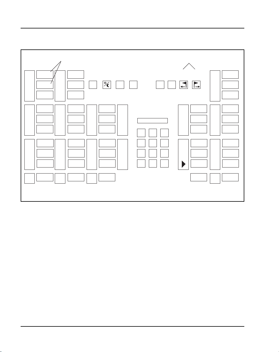
Page 66 of 504 Attendant consoles
Figure 14
M2250 key designations in Shift mode (QMT2 not enabled)
TGB7
TGB6
TGB5
TGB4
TGB3
TGB2
TGB1
TGB0
Note
ICI9
ICI8
ICI7
ICI6
ICI5
ICI4
ICI3
ICI2
ICI1
ICI0
CAS BSYF1OMN
C/H
LPK5
LPK4
LPK3
LPK2
LPK1
LPK0
RLS
VDH
F2
1 2 3
4 5 6
7 8 9
*
BLF Functions only
CGMSDMODE
DMN SS
VUP
F4
F3
EX SR
EX DS
RL SR
RL DS
BLF
0
#
SHIFT
HOLD
FEAT9
FEAT8
FEAT7
FEAT6
FEAT5
FEAT4
FEAT3
FEAT2
FEAT1
FEAT0
553-AAA0581
553-3001-367 Standard 3.00 August 2005
Page 67
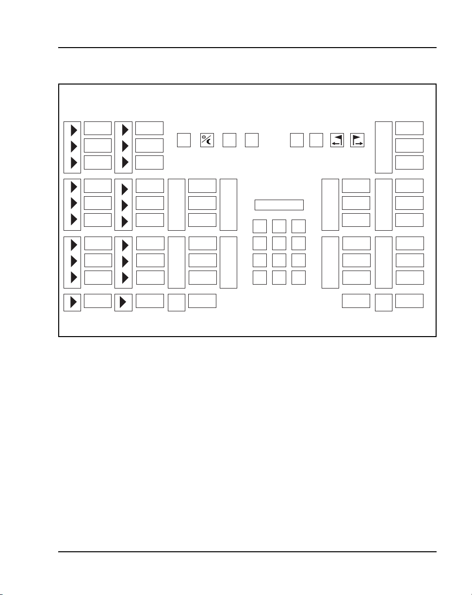
Attendant consoles Page 67 of 504
Figure 15
M2250 key designations in Unshift mode (QMT2 enabled)
ICI09
ICI08
ICI07
ICI06
ICI05
ICI04
ICI03
ICI02
ICI01
ICI00
ICI19
ICI18
ICI17
ICI16
ICI15
ICI14
ICI13
ICI12
ICI11
ICI10
CAS BSYF1OMN
C/H
LPK5
LPK4
LPK3
LPK2
LPK1
LPK0
RLS
VDH
F2
1 2 3
4 5 6
7 8 9
*
SS SDVUP
DMN
F4
F3
EX SR
EX DS
RL SR
RL DS
CONF 6
0
#
SHIFT
HOLD
FEAT9
FEAT8
FEAT7
FEAT6
FEAT5
FEAT4
FEAT3
FEAT2
FEAT1
FEAT0
553-AAA0583
Telephones and Consoles Description, Installation, and Operation
Page 68
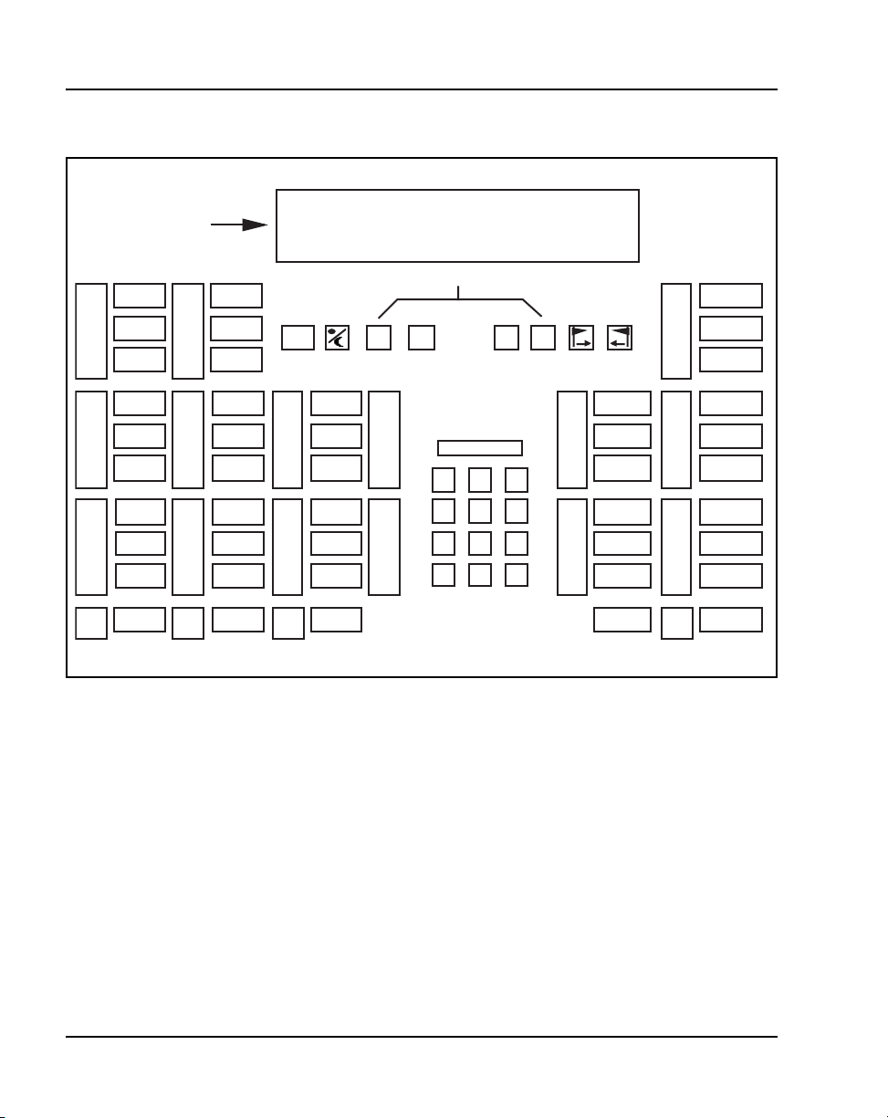
Page 68 of 504 Attendant consoles
Figure 16
M2250 designations in Unshift mode (QMT2 not enabled)
LCD Display
Screen
(4 or 2 lines
for M2250)
ICI9
ICI8
ICI7
CAS
C/H
BSY
F1 F2
Scrolling
F3
F4
SS SD
FEAT9
FEAT8
FEAT7
ICI6
ICI5
ICI4
ICI3
ICI2
ICI1
ICI0
LPK5
LPK4
LPK3
LPK2
LPK1
LPK0
RLS
1 2 3
4 5 6
7 8 9
0
*
#
Cross-connecting attendant consoles
Terminations are located on the vertical side of the distributing frame when
frame-mounted blocks are used and located in the blue field when
wall-mounted blocks are used.
Line circuit card (TN) terminations are located on the horizontal side of the
distributing frame when frame-mounted blocks are used and located in the
white field and wall-mounted blocks are used.
Follow the steps in Procedure 12 on page 69 to cross-connect attendant
consoles.
EX SR
EX DS
RL SR
RL DS
CONF6
SHIFT
HOLD
FEAT6
FEAT5
FEAT4
FEAT3
FEAT2
FEAT1
FEAT0
553-AAA0584
553-3001-367 Standard 3.00 August 2005
Page 69

Attendant consoles Page 69 of 504
Procedure 12
Cross-connecting attendant consoles
1 Locate the attendant console terminations at the cross-connect terminal.
2 Connect Z-type cross-connecting wire to the leads of the attendant
console.
3 Locate the line circuit card (TN) terminations.
4 Run and connect the other end of the cross-connecting wire to the
assigned TN terminal block.
End of Procedure
Refer to Table 6 for details on Z-type cross-connecting wire and Table 7 on
page 70 for a list of inside wiring colors.
Table 6
Z-type cross-connecting wire
Size Gauge Color Designation
1 pr 24 Y-BL Tip
BL-Y Ring
3 pr 24 W-BL Voice T
BL-W Voice R
W-O Signal T
O-W Signal R
W-G Power
G-W Power
Telephones and Consoles Description, Installation, and Operation
Page 70
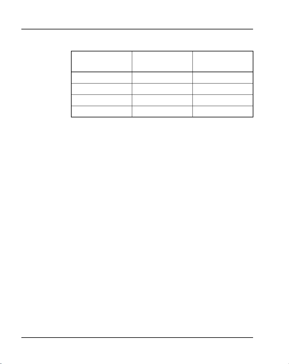
Page 70 of 504 Attendant consoles
Table 7
Inside wiring colors
Z station wire 16/25-pair cable
G W-BL First pair Tip
R BL-W First pair Ring
BK W-O Second pair Tip
Y O-W Second pair Ring
Connect to
equipment TN
553-3001-367 Standard 3.00 August 2005
Page 71
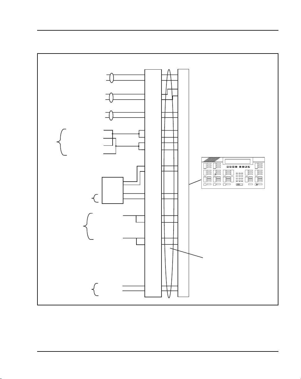
Figure 17
M2250 attendant console cross-connections
Cross connect
block
W-BL
BL-W
W-OR
OR-W
W-SL
SL-W
R-OR
•
OR-R
R-G
•
G-R
Note 1
To 1st TN
To 2nd TN
To 3rd TN
To 4th TN Tip
To 4th TN Ring
To 5th TN Tip
To 5th TN Ring
TCM Primary
TCM Secondary
ASM
+AUX
•
–AUX
•
Attendant consoles Page 71 of 504
26
1
27
2
30
5
32
7
33
8
Part of Power Fail
or Energy Transfer
Major Alarm
Note 2
Code Blue
GND
TC
GND
ALARM
+ VPS
VPS RTN
Relay 2
Relay 1
BK-BL
BL-BK
BK-BR
BR-BK
Y-BL
BL-Y
Y-OR
OR-Y
V-SL
SL-V
36
11
39
14
41
16
50
25
M2250 Console
(console connector)
42
17
25 pair cable from console to MDF
553-AAA0585
Telephones and Consoles Description, Installation, and Operation
Page 72

Page 72 of 504 Attendant consoles
The following notes refer to Figure 17 on page 71, which illustrates the
M2250 attendant console cross-connections.
Note 1: The M2250 is powered by means of the line circuits. In addition
to the primary TN, secondary TN, and ASM TN, two TNs are cabled to
the M2250 using the +AUX and –AUX leads. The maximum loop length
is 3000 ft of 24 AWG wire.
Note 2: When additional options are used (BLF or display backlight
option), an additional 16 V DC power supply is required. The 16 V DC
source is cabled using +VPS and VPS RTN leads. The maximum
distance from the console to the power source is 120 feet of 24 AWG
wire. Please note: if both options are installed, only one 16 V DC power
supply is required.
Note 3: Nortel recommends that five consecutive TNs on the line circuit
be allocated for each console.
Note 4: When used with the ISDLC, the M2250 requires NT8D02 or
later.
Note 5: The third TN must be cross-connected to the console cable
WH/SL pair whether or not an ASM (Attendant Supervisory Module) is
installed. This third TN provides additional console power which is
required.
Table 8 on page 73 explains where each M2250 cable pair is connected.
Table 9 on page 75 lists the M2250 typical cross-connections.
553-3001-367 Standard 3.00 August 2005
Page 73

Attendant consoles Page 73 of 504
Table 8
M2250 attendant console connections (Part 1 of 3)
Mounting cord 16/25-pair connector cable
Lead
designation
TCM primary 26
TCM secondary 27
Attendant
Supervisory
Module
Spare 31
+AUX 32
–AUX 33
Spare 34
Pin
number
1
2
30
5
6
7
8
9
Pair
number
1T
R
2T
R
5T
R
6T
R
7T
R
8T
R
9T
R
Color Connected to
W-BL
BL-W
W-O
O-W
W-SL
SL-W
R-BL
BL-R
R-O
O-R
R-G
G-R
R-BR
BR-R
TN #1
TN #2
TN #3
TN #4
TN #5
Telephones and Consoles Description, Installation, and Operation
Page 74

Page 74 of 504 Attendant consoles
Table 8
M2250 attendant console connections (Part 2 of 3)
Mounting cord 16/25-pair connector cable
Lead
designation
Spare 35
Power Fail or
Energy Transfer
Spare
Spare
Spare
Spare
GND
Major Alarm
Spare 40
VPS 41
Pin
number
10
36
11
37
12
38
13
39
14
15
16
Pair
number
10T
R
11T
R
12T
R
13T
R
14T
R
15T
R
16T
R
Color Connected to
R-SL
SL-R
BK-BL
BL-BK
BK-O
O-BK
BK-G
G-BK
BK-BR
BR-BK
BK-SL
SL-BK
Y- B L
BL-Y
GND (Note 1)
TC (Note 2)
GND (Note 1)
ALM (Note 2)
VPS RTN 42
17
Spare
Code Blue 50
25
553-3001-367 Standard 3.00 August 2005
17T
R
25T
R
Y- O
O-Y
Y- S L
SL-Y
Relay 2
Relay 1
Page 75

Attendant consoles Page 75 of 504
Table 8
M2250 attendant console connections (Part 3 of 3)
Mounting cord 16/25-pair connector cable
Lead
designation
Note 1: Connect to Pin 3 or 28 of the appropriate PFJ5 terminal block.
Note 2: Connect TC to Pin 29 or 5 and ALM to Pin 4 or 31 of the
appropriate PFJ5 terminal block.
Table 9
M2250 typical cross-connections (Part 1 of 2)
Pair Pins
1T
1R
2T
2R
3T
3R
4T
4R
26
1
27
2
28
3
29
4
Pin
number
Pair
Color
W-BL
BL-W
W-O
O-W
W-G
G-W
W-BR
BR-W
Pair
number
Color Connected to
DLC
Connections
Unit
0
Unit
1
Unit
2
Unit
3
ISDLC
Connections
Unit
0
Unit
8
Unit
1
Unit
9
5T
5R
6T
6R
7T
7R
30
5
31
6
32
7
Telephones and Consoles Description, Installation, and Operation
W-S
S-W
R-BL
BL-R
R-O
O-R
Unit
4
Unit
5
Unit
6
Unit
2
Unit
10
Unit
3
Page 76

Page 76 of 504 Attendant consoles
Table 9
M2250 typical cross-connections (Part 2 of 2)
Pair Pins
8T
8R
9T
9R
10T
10R
11T
11R
12T
12R
13T
13R
14T
14R
33
8
34
9
35
10
36
11
37
12
38
13
39
14
Pair
Color
R-G
G-R
R-BR
BR-R
R-S
S-R
BK-BL
BL-BK
BK-O
O-BK
BK-G
G-BK
BK-BR
BR-BK
DLC
Connections
Unit
7
Unit
8
Unit
9
Unit
10
Unit
11
Unit
12
Unit
13
ISDLC
Connections
Unit
11
Unit
4
Unit
12
Unit
5
Unit
13
Unit
6
Unit
14
15T
15R
16T
16R
553-3001-367 Standard 3.00 August 2005
40
15
41
16
BK-S
S-BK
Y- B L
BL-Y
Unit
14
Unit
15
Unit
7
Unit
15
Page 77

Operation
M2250 configurations
Attendant consoles Page 77 of 504
This section contains operating procedures for the M2250 attendant console.
The attendant console faceplate layout is shown in Figures 14 through 16,
starting on page 66. Refer to these figures as the basis for component location
references throughout this section.
The M2250 attendant console can be configured to operate with the QMT2
feature, which is provided by a QMT2 add-on module incorporated in the
console. Instead of having to add a keystrip unit, the technician can set a dip
switch on the keyboard/controller Printed Circuit Panel (PCP) to ON (enable
QMT2) or OFF (disable QMT2). It is important that the system software
configuration and the QMT2 dip switch be set correctly.
For more information, refer to the section on LD15 in the following
documents:
• Features and Services (553-3001-306)
• Software Input/Output: Administration (553-3001-311)
QMT2 feature disabled
When the QMT2 feature is disabled, the following conditions apply:
• If the console is not in Shift mode, keystrip AK is inactive.
• If the console is in Shift mode, the keys in strip AK function as Trunk
Group Busy (TGB) keys, if configured in the system software.
• If the operator presses any of these keys, the associated trunk group is
busied out.
• The triangle points aimed to the left of keystrip AK are never active.
• If the operator presses any key outside keystrip AK when the console is
in Shift mode, the console performs the function associated with that key.
The Shift indicator remains on.
• The keys in keystrip BK function as Incoming Call Identification
(ICI) keys.
Telephones and Consoles Description, Installation, and Operation
Page 78

Page 78 of 504 Attendant consoles
QMT2 feature enabled
When the QMT2 feature is enabled, the following conditions apply:
• If the console is not in Shift mode, the keys in strip AK and/or BK
function as Incoming Call Identification (ICI) keys.
• If the console is in Shift mode, the keys in keystrips AK and BK function
as Trunk Group Busy (TGB) keys. That is, they imitate the keystrips of
the QMT2 add-on module as follows:
— The LCD indicators pointing to the left indicate busy trunks.
— The LCD indicators pointing to the right indicate incoming calls.
Attendant PC requirements
To install the PC-based Console software application, a PC-compatible
Pentium system is required, with the following:
• minimum 16 MB RAM
• hard disk with at least 10 MB free disk space
• 17-inch SVGA color monitor
• 16 bit sound board
• Network interface adapter
• RS232 serial port
For complete installation and operation instructions, refer to the
Attendant PC: Description, Installation, and Operation (553-3001-320).
553-3001-367 Standard 3.00 August 2005
Page 79
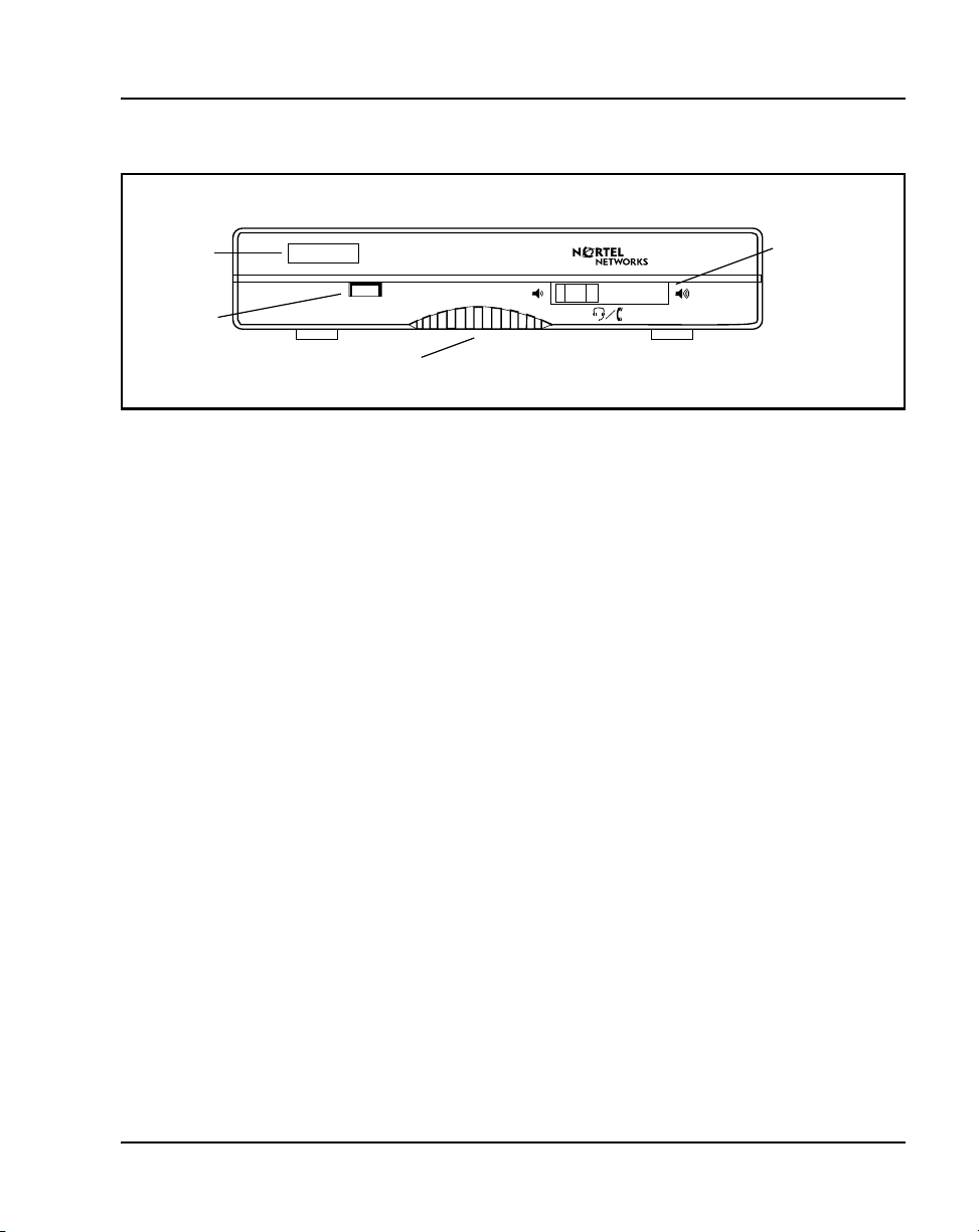
Figure 18
PC Console Interface Unit
Attendant consoles Page 79 of 504
brandline
insert
Status LED
alerter speaker
M2250 feature key modes
Functions shown for some of the feature keys in Table 3 page 51 vary
depending on which console mode is in effect while the key is being pressed.
Table 10 on page 80 lists the various alternate feature key functions.
When a feature key is pressed while the attendant console is in a mode other
than normal or Level 1, nothing happens.
When in the normal call processing mode, access the Level 1 mode by
pressing the Shift key. The LCD indicator beside the shift key lights and
remains on throughout all options and menus. It goes out only upon return to
normal call processing. All call processing keys that do not have a dual
function perform normally while the console is in Level 1 mode. Press the
Shift key again to return to normal call processing.
headset/handset
volume control
553-AAA0576
On the M2250 attendant console, press the pound (#) key to exit from any
submenu from the Options menu, or from the Diagnostics menu to normal
operating mode. Press the Shift key to return to the Level 1 mode.
Level 1 mode also provides access to additional call processing features, as
well as to options and maintenance features. One of the additional call
processing features is access to Trunk Group Busy (TGB) keys that are
locked out in normal mode. For example, in normal mode, there are ten
Telephones and Consoles Description, Installation, and Operation
Page 80
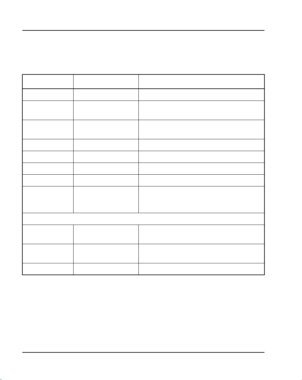
Page 80 of 504 Attendant consoles
available TGB keys on the M2250. With QMT2 enabled, the number of TGB
keys on each console is doubled.
Table 10
Softkey alternate functions
Key Operational mode Function
F1 Normal Selects line 2 of the display for scrolling.
F2 Normal Scrolls left on the selected line, at 8 characters
per step.
F3 Normal Scrolls right on the selected line, at 8 characters
per step.
F4 Normal Selects line 3 of the display screen for scrolling.
Shift, F1 Level 1 Selects the Options menu.
Shift, F2 Level 1 Turns down the alerter speaker volume.
Shift, F3 Level 1 Turns up the alerter speaker volume.
Shift, F4 Level 1 Selects the Diagnostic menu. (A password must
be entered on the M2250 before the Diagnostics
menu appears.)
Example:
Press Shift and
F1 (in sequence)
553-3001-367 Standard 3.00 August 2005
Options menu The Options menu is displayed.
Press dial pad key 1 Accesses Contrast menu. (Refer to user guide
Press dial pad key # Returns to Options menu.
for contrast setting routines.)
Page 81
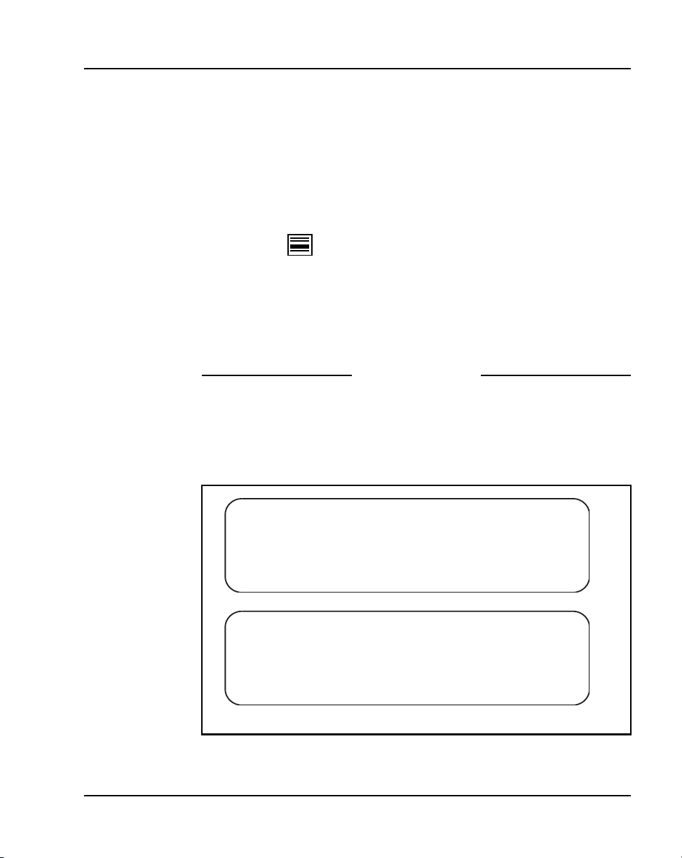
M2250 console diagnostics
Use the Diagnostics menu to check the functions of the console and to
perform tests. To enter the Diagnostics mode, use Procedure 13. Figure 19
shows the main Diagnostics menu for the M2250 attendant console.
Procedure 13
Entering the M2250 Diagnostics mode
1 Press the Shift key.
2 Press the key (F4 function key).
3 On M2250 consoles, enter the password 9999.
4 Press the asterisk (*) key to enter Diagnostics menu 1. To toggle between
menu 1 and menu 2, press the asterisk (*) key.
5 To quit the Diagnostics mode, press the octothorpe (#) key.
Follow the procedures listed below to perform the Diagnostic tests.
Figure 19
Console Diagnostics menus
Attendant consoles Page 81 of 504
End of Procedure
DIAGNOSTICS MENU:
1. KEYBOARD
4. ICs
DIAGNOSTICS MENU:
1. DISPLAY
4. CONTROL
2. LAMPS
5. LAMP FIELD
<next>
*
2. FIRMWARE
5. RESET
<next>
*
3. DATA PORT
6. ALERTER
# <exit>
3. QMT2
# <exit>
{ 1 }
{ 2 }
553-AAA0577
Telephones and Consoles Description, Installation, and Operation
Page 82
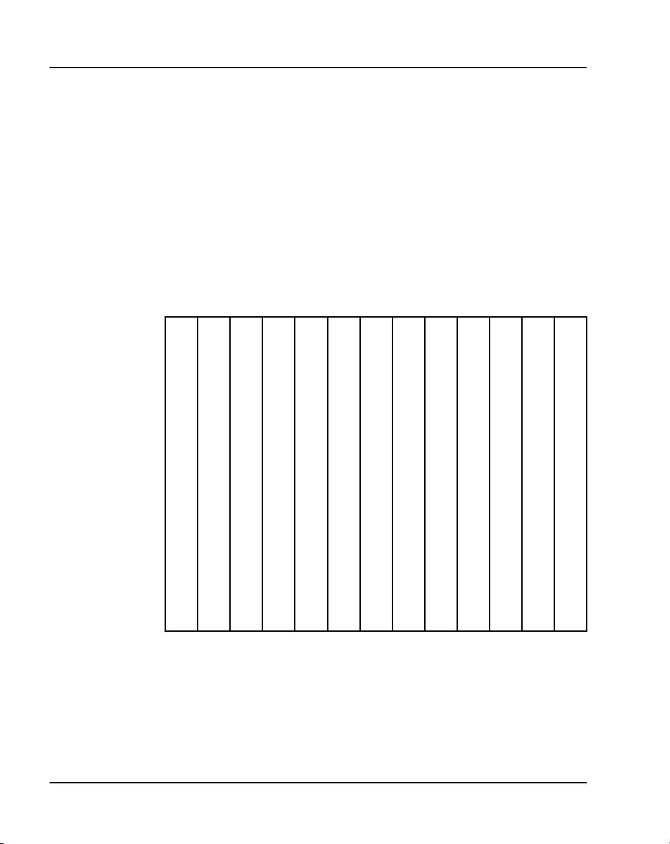
Page 82 of 504 Attendant consoles
Procedure 14
Testing the Keyboard
Use this procedure to check the functionality of each key on the console.
When a key is pressed, its location code is displayed within parentheses. For
example, (00) denotes the upper left-hand ICI key.
1 From Diagnostics menu 1, press 1.
2 Press any key on the console. The display shows the key’s location code,
indicating that the key is functional. Table 11 shows the key location
codes.
3 Press the octothorpe (#) key to exit and return to Diagnostics menu 1.
Table 11
Key location codes for console diagnostics
22 21 20 34 54 60 61 62
00 10 70 80 90
01 11 71 81 91
02 12 72 82 92
03 13 23 63 73 83 93
04 14 24 64 74 84 94
05 15 25 35 45 55 65 75 85 95
06 16 26 36 46 56 66 76 86 96
07 17 27 37 47 57 67 77 87 97
08 18 28 38 48 58 68 78 88 98
09 19 29 69 79 89 99
553-3001-367 Standard 3.00 August 2005
Page 83

Attendant consoles Page 83 of 504
Procedure 15
Testing the LCD indicators
Use this procedure to check the functionality of each LCD indicator on the
console.
1 From the Diagnostics menu 1, press 2.
2 Press 1 to turn all lamps ON. Press the asterisk (*) to turn each lamp OFF
one by one.
3 Press 2 to turn all lamps OFF. Press the asterisk (*) to turn each lamp ON
one by one.
4 Press the octothorpe (#) to exit and return to Diagnostics menu 1.
End of Procedure
Procedure 16
Testing the data port
Use this procedure to perform a loopback test on the RS-232 port at the back
of the console. Before performing the test, a connector (25-way D-plug) with
pin 2 shorted to pin 3 should be inserted in RS-232 port. A failure code is
displayed if any error is found.
1 From Diagnostics menu 1, press 3. The display shows OK if the test is
successful.
2 Press the asterisk (*) to repeat the loopback test.
3 Press the octothorpe (#) to exit and return to Diagnostics menu 1.
End of Procedure
Procedure 17
Testing the ICS
Use this procedure to check the functionality of any peripheral devices
connected to the User Interface Printed (UIP)and the Audio System Interface
Printed (ASIP) microprocessor circuit cards within the console. A failure code
is displayed if any error is found.
1 From Diagnostics menu 1, press 4.
2 Press the asterisk (*) to perform the ICS test.
Telephones and Consoles Description, Installation, and Operation
Page 84

Page 84 of 504 Attendant consoles
3 Press the octothorpe (#) to exit and return to Diagnostics menu 1.
Procedure 18
Testing the Busy Lamp Field/Console
Graphics Module
Use this procedure to check the functionality of the BLF/CGM. Once in this
menu, the dial pad is in CGM mode. When any dial pad keys are pressed,
except the octothorpe (#) key, the keys are echoed on the BLF/CGM.
1 From Diagnostics menu 1, press 5.
2 Press keys from 0 – 9 and the asterisk (*) on the dial pad. Check the CGM
to see that they are echoed.
3 Press the octothorpe (#) to exit and return to Diagnostics menu 1.
Note: For more information on installation and operation of this feature,
see “Busy Lamp Field/Console Graphics Module” on page 32, or refer to
the Busy Lamp Field/Console Graphics Module User Guide.
End of Procedure
End of Procedure
Procedure 19
Checking the Alerter
Use this procedure to check the pitches and volume levels of the alerter and
auxiliary tone channel.
1 From Diagnostics menu 1, press 6.
2 Follow these instructions in any order:
Press key 1 to turn the buzz and auxiliary tones ON.
Press key 2 to turn the buzz and auxiliary tones OFF.
Press key 3 to increase the pitch of the buzz and auxiliary tones.
Press key 4 to decrease the pitch of the buzz and auxiliary tones.
Press key 5 to increase the volume of the buzz and auxiliary tones.
Press key 6 to decrease the volume of the buzz and auxiliary tones.
3 Press the octothorpe (#) to exit and return to Diagnostics menu 1.
553-3001-367 Standard 3.00 August 2005
End of Procedure
Page 85

Attendant consoles Page 85 of 504
Procedure 20
Testing the Display
Use this procedure to check the functionality of the alphanumeric display
panel. Cycle through a number of different display patterns to check for visual
defects.
1 From Diagnostics menu 2, press 1.
2 Press the asterisk (*) to change the display screen pattern. Continue
changing the pattern until all the patterns have been cycled through.
3 Press the octothorpe (#) to exit and return to Diagnostics menu 1.
End of Procedure
Procedure 21
Displaying the firmware version numbers
Use this procedure to display the release and issue numbers of the firmware
installed on the UIP and ASIP microprocessor circuit cards.
1 From Diagnostics menu 2, press 2. The display shows the firmware
release and issue numbers, as shown below:
DIAGNOSTICS: FIRMWARE
ASIP: XX XX
UIP: XX XX
2 Press the octothorpe (#) to exit and return to Diagnostics menu 1.
End of Procedure
Procedure 22
Displaying and resetting the QMT2 switch status
Use this procedure to display the current state of the QMT2 dip switch inside
the console and to change the setting for verification testing (LD 31). After a
change, the actual switch setting will return to its original state after a time-out
period of about three minutes.
1 From Diagnostics menu 2, press 3.
2 Press the asterisk (*) to toggle between QMT2 ON and OFF.
Telephones and Consoles Description, Installation, and Operation
Page 86

Page 86 of 504 Attendant consoles
3 Press the octothorpe (#) to exit and return to Diagnostics menu 1.
Procedure 23
Toggling control gates
Use this procedure to turn the conference bridge analog control gates, the
auxiliary tone channel, and the Code Blue Relay ON or OFF. Note that the
auxiliary control only affects the control gate on the ASIP circuit card. To
actually generate a tone, use the Alerter menu.
1 From Diagnostics menu 2, press “4.”
DIAGNOSTICS: CONTROL
1. SCR 2. DST 3. ARX 4. ATX 5. TON 6. REL
{ 0 } { 0 } { 0 } { 0 } { 0 } { 0 }
* <OFF> # <exit>
2 Follow the appropriate instruction below:
Press key 1 to toggle the primary control gate between ON and OFF.
Press key 2 to toggle the secondary control gate between ON and OFF.
End of Procedure
Press key 3 to toggle the attendant receive control between ON and OFF.
Press key 4 to toggle the attendant transmit control between ON and
OFF.
Press key 5 to toggle the auxiliary tone control between ON and OFF.
Press key 6 to toggle the relay control between ON and OFF.
3 Press the asterisk (*) to turn all the control gates OFF.
4 Press the octothorpe (#) to exit and return to Diagnostics menu 1.
553-3001-367 Standard 3.00 August 2005
End of Procedure
Page 87

Reset
To perform a hard reset of the console, from Diagnostics menu 2, press 5. The
reset is performed immediately. All devices and memory on the UIP and
ASIP boards are reset as if the power cord were unplugged and plugged in
again.
M2250 failure codes
A failure code appears on the display in response to the detection of a
hardware fault.
Refer to Table 12 for an explanation of failure codes and possible solutions.
Table 12
M2250 failure codes (Part 1 of 2)
Printed
Failure
code
circuit
pack (PCP)
Reason What to do
Attendant consoles Page 87 of 504
40H UIP The PSG, U13, is not
responding.
20H UIP The RTC, U16, is faulty. Same as for 40H.
10H UIP The RAM IC, U1, is faulty. Same as for 40H.
08H UIP A key in column A is stuck. Unplug the line cord.
09H UIP A key in column B is stuck. Same as for 08H.
Telephones and Consoles Description, Installation, and Operation
Unplug the line cord and plug it in
again. If the failure code still appears,
there is an electrical fault in the
console, and it should be returned.
Note: Log the failure code with the
returned unit, as it gives an indication
of which component has failed.
Free the key if it is stuck.
Plug in the line cord.
If the failure code still appears, the
console is faulty and should be
returned.
Page 88

Page 88 of 504 Attendant consoles
Table 12
M2250 failure codes (Part 2 of 2)
Printed
Failure
code
0AH UIP A key in column C is stuck. Same as for 08H.
circuit
pack (PCP)
Reason What to do
0BH UIP A key in column D0 is
stuck.
0CH UIP A key in column D1 is
stuck.
0DH UIP A key in column D2 is
stuck.
0EH UIP A key in column E is stuck. Same as for 08H.
0FH UIP A key in column F is stuck. Same as for 08H.
A0H ASIP The RS-232 has failed the
loopback test.
90H ASIP ASM A44#3, U1, is faulty. Same as for 40H.
88H ASIP Secondary A44#2, U2, is
faulty.
Same as for 08H.
Same as for 08H.
Same as for 08H.
Check to see if the loopback
connector is inserted. If not, insert it
and perform the loopback test again.
If the failure code still appears, turn
the console off and on while the
connector is inserted.
Perform the loopback test again. If the
failure code still appears, the console
is faulty and should be returned.
Same as for 40H.
84H ASIP Primary A44#1, U1, is
faulty.
82H ASIP The UART, U5, is faulty. Same as for 40H.
81H ASIP The RAM, U8, is faulty. Same as for 40H.
553-3001-367 Standard 3.00 August 2005
Same as for 40H.
Page 89
The failure codes produced by the firmware in response to the detection of a
hardware fault are bit-significant as follows:
B7 B6 B5 B4 B3 B2 B1 B0
0 PSG RTC RAM KEYS c2* c1* c0*
1 ASIP RS-232 A44#3 A44#2 A44#1 UART RAM
* Refers to key’s column number.
Note: Bit 7 indicates whether the failure occurred on the user interface
printed circuit card (UIP) (B7=0) or on the audio and system interface
printed circuit card (ASIP) (B7=1).
In most instances, the failure code accurately identifies the faulty hardware
component. However, if the microprocessor is faulty, the readings may be
unreliable or misleading.
Failure code A0H is always shown if the loopback test has not been
performed. Refer to “Testing the data port” on page 83.
M2250 feature operation
Attendant consoles Page 89 of 504
Time and date
On the M2250, the time and date are automatically downloaded from the
system on power-up or console reset. The time and date are downloaded by
the switch whenever it runs a lamp audit. Only the visual format can be
changed.
Trunk Group Busy indicators
Trunk Group Busy (TGB) indicators show the status of each group of trunks.
If a TGB indicator is on steadily, the attendant has busied out all trunks in that
group by pressing the Shift key plus the TGB key. If a TGB indicator is
flashing, all the trunks in that group are actually busy.
In Supervisory mode, TGB indicators show the status of other consoles in the
customer group. If the indicator is off, the attendant position is in a Position
Telephones and Consoles Description, Installation, and Operation
Page 90

Page 90 of 504 Attendant consoles
Busy mode. When an indicator associated with a particular attendant is on,
the attendant is available to service calls.
Note: The M2250 attendant console must be equipped with the
Attendant Supervisory Module (NT7G10AA) to allow attendant
supervision.
Incoming Call Indicators
Incoming Call Indicators (ICI) display the various types of incoming calls
presented to the attendant console. They also indicate the number of calls and
the length of time calls have been queued.
• If the indicator is on, one call has been queued for less than a certain
length of time (as defined by software).
• If the indicator is flashing, one call has been queued for more than the
defined length of time, or there is more than one call in the queue.
Night service/busy
When the Shift key is off, press the Busy key to put the attendant console into
Position Busy mode. When the Shift key is on, press the Busy key to put the
console into Night Service mode. To return to normal operating mode, press
the Busy key again.
In a multi-console system, activating Night Service mode will busy out all
attendant consoles in the system.
Enhanced Night Service
This feature allows Public Network (Central Office [CO], Direct Inward Dial
[DID], Foreign Exchange [FEX], and Wide Area Telephone service [WAT])
trunks to be assigned to specific Directory Numbers (DN) during Night
Service.
With this feature each customer will be able to assign Public Network trunks
to one of nine Night Groups. Each Night Group will allow the customer to
define up to nine Night DNs. During Night Service incoming calls will be
routed to one of the Night DNs defined for the group. The actual DN the call
will be routed to is determined by the Night Service Option number selected
at that time.
553-3001-367 Standard 3.00 August 2005
Page 91

Attendant consoles Page 91 of 504
The customer will also be able to define whether Night Call Waiting tone will
be given to Night stations. With Night Call Waiting tone allowed, busy Night
stations are notified when an incoming call is terminating on them. The
incoming call will be queued on the Night station until it becomes idle. When
the Night station becomes idle, the incoming call will be presented.
This enhancement allows incoming DID trunks to be queued against busy
Night stations, thereby making the operation of the DID trunks the same as
for all other Public Network trunks.
Attendant Blocking of DN
The Attendant Blocking of DN (ABDN) feature enables the attendant to
block a DN for a telephone from receiving or making calls. This is
particularly useful when a caller dials the attendant DN and requests an
external (long distance) call. If the caller chooses to disconnect until the
attendant successfully places the call, the requesting DN becomes idle and
can receive or make calls. Therefore, the requesting DN could be busy when
the attendant establishes the requested call.
To prevent the requesting DN from being busy when the requested call is
completed, the attendant can block the DN from making or receiving calls. To
callers attempting to contact the blocked DN, the line appears busy. To a
caller attempting to use the blocked DN, the line is connected to the attendant.
When the attendant completes the external call, the attendant can call the
blocked DN and extend the call. This feature applies to both stand-alone and
ISDN network environments.
The Attendant Blocking of DN feature is available on the M2250 attendant
consoles. It is not valid on M2616 telephones used as attendant consoles.
Attendant and Network Wide Remote Call Forward
This modification to the Remote Call Forward feature (RCFW) allows a user
to program a call forward Directory Number from any attendant console or
station throughout the network. An RFW key on the attendant console allows
an attendant to view any station’s call forward status and to activate or
deactivate call forward for a station.
Telephones and Consoles Description, Installation, and Operation
Page 92

Page 92 of 504 Attendant consoles
Refer to ISDN Primary Rate Interface: Features (553-3001-369) for further
details.
Network Attendant Services
This feature allows attendant services to be distributed anywhere within a
Meridian ISDN network. If, at the time of an attendant request, attendant
services are not available at a station’s local node, connection to an attendant
at a remote node takes place. Call treatment is the same as for a connection to
a local attendant node.
Call processing
The attendant answers an incoming call by pressing the flashing loop key.
To answer a specific type of incoming call, press the ICI key next to the
appropriate ICI indicator. This removes the call from the queue and presents
it to the attendant.
ICI key assignments
An ICI key may be assigned more than one call type. Refer to Software Input/
Output: Administration (553-3001-311). If the Attendant Call Party Name
Display (ACPND) feature is equipped, all incoming calls are displayed by
calling party name or external call source. The following examples list
possible ICI key assignments:
• Attendant Intercept indicates that a call is being made by a station to a
facility to which that station is restricted, and the call has been routed to
the attendant console.
• Listed Directory Numbers (maximum four) indicates that a call is
being made to an attendant console associated with one of the listed
directory numbers.
• Dial 0 indicates that a station that is not fully restricted has dialed 0.
• Fully Restricted Station indicates that a fully restricted station has
dialed 0.
• Foreign Exchange indicates that the incoming call is from a foreign
exchange.
553-3001-367 Standard 3.00 August 2005
Page 93

Attendant consoles Page 93 of 504
• Wide Area Telephone Service indicates that the incoming call
originated at a wide area telephone exchange.
• Recall
indicates that a camped-on call or a call extended to an idle station
has not been answered for 30 seconds or that a station is recalling the
attendant.
• Call Forward indicates that the call is being forwarded to the console
from a station within the system.
• Tie Trunk indicates that the incoming call is on a tie trunk.
Operating keys
The operating key/lamp strips CI/CK, DI, EI, and FI/FK allow the attendant
to process calls from the console.
Key/lamp strips CI/CK and FI/FK have permanently assigned functions as
given in the following list.
• Release
allows the attendant to release a call presented to the console.
When the LCD associated with the RLS key is lit, it indicates that no
incoming calls are being presented to the console.
• Loop Keys/Lamps allow the attendant to answer and originate calls
from the console. The first call in the incoming queue is automatically
presented to an idle loop key. Subsequent calls are queued and presented
to a loop key when a loop becomes idle. Call selection is made by
pressing the required ICI key. This action causes the call, which was
automatically presented to the loop key by the system, to be replaced by
the selected incoming call. In all cases, when the loop key is pressed, all
ICIs go dark except the one associated with the call presented to the
loop key.
• Position Busy enables the attendant to put the console in Position Busy
mode. All calls directed to a console in Position Busy mode are
redirected to a free console in multiconsole installations or to the night
connection in single console installations. When a console is in Position
Busy mode, “BUSY” is shown on line 4 of the display.
Telephones and Consoles Description, Installation, and Operation
Page 94

Page 94 of 504 Attendant consoles
• Night Service permits incoming calls to the attendant to be routed to a
preselected station. The Night Service key enables the attendant to assign
the Night Directory Number (DN) and to initiate Night Service. When
assigning the Night Service DN, “NIGHT” flashes on line 4 of the
display. When Night Service is on, “NIGHT” appears without flashing
on the display.
• In a multiconsole system, activating Night Service will busy out all
attendant consoles in the system.
• Hold allows the attendant to hold an active call at the console while
serving other calls.
• Conference permits the attendant to set up a conference of up to five
conferees plus the attendant.
• Release Destination
allows the attendant to release the called party from
a call held at the console while holding the calling party.
• Release Source allows the attendant to release the calling party from a
call held at the console while holding the called party.
• Signal Source and Destination allows the operator to recall either party
to a call held on the console.
• Exclude Destination excludes the called party from an established call
held at the console, allowing the attendant to speak privately with the
calling party.
• Exclude Source excludes the calling party from an established call
held at the console, allowing the attendant to speak privately with the
called party.
Feature keys
Any of the keys on keystrip FK can be assigned any of the optional features
in the list that follows except the Barge-In and Busy Verify features. These
require five LCD indicator states (off, on, and flash at 30, 60, or 120 impulses
per minute). If Barge-In or Busy Verify is required, it must be assigned to
keys FK-0 and FK-1.
553-3001-367 Standard 3.00 August 2005
Page 95

Attendant consoles Page 95 of 504
All other features may be assigned to any of the keys on strip FK. Refer to
Software Input/Output: Administration (553-3001-311) for additional
information. The following are some of the more common feature keys:
• Attendant End to End Signaling enables the attendant to send dual tone
multifrequency (DTMF) signals to either the source or destination party.
• Busy Verify allows the attendant to confirm that a station returning a
busy signal is actually being used.
• Barge-In allows the attendant to enter an established trunk connection
for the purpose of talking to one or both parties.
• Paging allows access to a public address facility.
• Speed Call allows numbers to be dialed automatically by pressing the
SPEED CALL key and dialing a 1- or 2-digit code.
Call Waiting indicator
The Call Waiting indicator indicates that there is a queue of calls to be
answered. When one or more calls are waiting, “CW” appears on line 4 of the
display. The CW display changes from steady to flashing when waiting calls
exceed a certain number or when a call has been waiting longer than a
specified time.
The maximum number of waiting calls and the maximum hold time for each
waiting call to be answered can be set with a data administration task. Refer
to Features and Services (553-3001-306) for more information.
An optional buzz is available to indicate when the first call enters the queue.
The number of waiting calls can be viewed on the LCD screen by pressing a
key assigned on the attendant console. On the M2250, the number of waiting
calls can be displayed continuously on line 4 of the display, if defined in
LD15 and selected from the Options menu.
Alarm indicators
Alarms appear on line 4 of the display. “MN” indicates a minor alarm
condition; “MJ” indicates a major alarm. A minor alarm is an indication of a
minor system failure affecting a limited number of lines or trunks. A major
alarm indicates that Emergency Transfer may have been initiated. See
“Emergency Transfer” on page 96.
Telephones and Consoles Description, Installation, and Operation
Page 96

Page 96 of 504 Attendant consoles
Emergency Transfer
If a major equipment or power failure halts local call processing, preselected
CO trunks are automatically connected to preselected stations (predetermined
and hard-wired at installation time) through relays in the system. Emergency
Transfer can also be activated manually by a switch underneath the attendant
console.
If the switch is activated while the console has power, the word
“EMERGENCY” appears on line 4 of the display.
Attendant Administration
Attendant Administration is an optional feature that allows the attendant to
modify some of the features assigned to selected telephone sets within the
attendant’s customer group. The attendant can enter a special program mode
with an assigned key.
Once in the program mode, the console key/lamp strips have different
functions from those during normal call processing. A plastic overlay can be
placed over the console keyboard to identify the altered key functions. Refer
to Features and Services (553-3001-306) for Attendant Administration
description and operating procedures.
Collect Call Blocking
The Collect Call Blocking feature enables a system administrator to block
long distance collect call service calls on incoming Direct Inward Dialing
(DID) and Public Exchange/Central Office trunks (analog or DT12).
Under the following conditions, the system sends a special answer signal to
the Central Office to indicate that collect calls cannot be accepted:
• The Collect Call Blocking (CCB) package 290 is enabled.
• The incoming route has CCB enabled via the CCB prompt in the Route
Data Block.
• The call is answered by a CCB user (that is, Collect Call Blocking
Allowed Class of Service or option).
553-3001-367 Standard 3.00 August 2005
Page 97

Attendant consoles Page 97 of 504
Classes of service and prompts are provided which enable administrators to
inhibit specific users from receiving collect DID and Central Office calls.
These can be configured for the following:
• PBX and BCS through the Collect Call Blocking Allowed/Denied
(CCBA/CCBD) option
• Attendant and Network Alternate Route Selection calls on a per customer
basis through CCBA/CCBD option
• Automatic Call Distribution (ACD) queues through the CCBA prompt
• Direct Inward System Access (DISA) through the CCBA prompt
• Tandem calls dialed with Coordinated Dialing Plan (CDP) (Trunk
Steering Code, Distant Steering Code) through the CCBA prompt
• Tandem non-CDP calls through the CCBA prompt in the Route Data
Block from the outgoing trunk route
When a call is answered by a CCB user, the system sends the CCB answer
signal in place of the regular signal for incoming DID/CO calls from the
routes with CCB enabled. If the call is a collect call, The CO will disconnect
the call.
Alarm Management
The Integrated Alarm Management feature is a series of subfeatures which
improve the handling of key alarm messages generated by the system and its
Application Processors.
It also clarifies existing alarm messages and makes attendant console alarm
lamp signals more meaningful. The system has three levels of alarm: critical,
major, and minor. The attendant console alarm lamp will light when critical
alarms occur.
Digital Trunk Interface – CIS
The CIS DTI trunk feature provides connectivity between the system and
digital trunks used in the Commonwealth of Independent States (CIS).
The CIS 2 Mbps DTI feature enables the system to connect digital DID/COT
trunks to a CIS Local Central Office and to a CIS Toll Exchange (through
Local CO and Public Network, or directly for incoming toll call connections).
Telephones and Consoles Description, Installation, and Operation
Page 98

Page 98 of 504 Attendant consoles
This link supports DID/COT trunking types, and requires that the system be
equipped with at least one CDTI2/CSDTI2 digital trunks pack, as well as
associated software.
DPNSS Executive Intrusion
Executive Intrusion (EI) allows an originating party to break into an
established call between two other parties (the wanted and the unwanted
parties) under certain circumstances. If intrusion succeeds, a conference takes
place on the wanted node between the originating, wanted and unwanted
parties.
EI succeeds in breaking into the call based on comparisons between the
Intrusion Capability Level (ICL) of the originating party and the Intrusion
Protection levels (IPL) of the wanted and unwanted parties.
The system provides Executive Intrusion from attendant consoles. Executive
Intrusion from Telephone Sets is not supported. However, a Meridian 1,
CS 1000M, or CS 1000S PBX will accept an EI activation request from an
ordinary set on a third party PBX.
Attendant Monitor
Attendant Monitor is a customer-defined option which allows the attendant to
monitor – in listen only mode – any established call involving a set or trunk
on the customer with or without the connected parties being aware that
monitoring is taking place (depending on the configuration of the customer
tone option).
The differences between the existing Busy Verify and Barge-in features and
the Attendant Monitor feature are the following:
• Attendant Monitor provides a listen only path for the attendant.
• There is no click sound given to the connected parties upon Attendant
connection when the no tone option is configured.
• The tone to the connected parties may or may not be given depending on
the customer tone options for Attendant Monitor.
• The display (if there is one) on any of the parties involved in the calls
does not indicate that the Attendant is monitoring.
553-3001-367 Standard 3.00 August 2005
Page 99

Attendant consoles Page 99 of 504
Busy Verify and Barge-in Enhancement
Attendant Monitor changes the operation of Busy Verify and Barge-in
slightly. Tone is now configurable. Busy Verify and Barge-in restrictions
relating to the Warning Tone Allowed/Denied Class of Service apply to
Attendant Monitor as well.
Attendant Forward No Answer
Attendant Forward No Answer allows two enhancements to existing
operations. The first enhancement permits calls presented to the attendant to
forward to a second attendant or the night DN when a customer-defined time
expires. The second enhancement allows DID or CO calls to any set during
night service to disconnect if not answered within a predefined number of
ring cycles.
Attendant Forward No Answer is selectable on a customer basis, and is
included in the package 134, AFNA.
Semi-Automatic Camp-On
Semi-Automatic Camp-On is an option to the current camp-on operation.
When the party to which a call is camped-on becomes free, the attendant is
recalled first instead of the wanted party being rung immediately. The
modification is implemented under the Semi-Automatic Camp-on (SACP)
package.
When an external call is camped on to a busy DN by an attendant or a set, the
called party receives a buzz (for digital sets) or a burst of tone (for analog
[500/2500-type] sets), indicating camp-on. Without SACP, if the called party
becomes idle within a customer-defined time, the camped-on call rings the
station immediately.
With SACP, if the called party becomes idle, the camped-on call recalls the
attendant instead of ringing the called party. The called party meanwhile is
kept busy from receiving any calls (but is still able to originate calls).
A programmable key, the Semi-Automatic Camp-on Recall (SACP) key is
included with the SACP feature.When a recall is presented to the console, the
RECALL ICI lamp and the SACP lamp light up. After answering the recall
from the calling party, the attendant can ring the called party by pressing the
Telephones and Consoles Description, Installation, and Operation
Page 100

Page 100 of 504 Attendant consoles
SACP key. The attendant can then hold the call on the console, or release the
call as usual.
When the attendant tries to present the call (after it has recalled to the
attendant) to the wanted party, this party may have originated another call. In
that case, the attendant receives the indication that the set is busy, and can
then camp-on the call again or release it, as usual. On a second camp-on, the
attendant must activate the SACP feature again, if needed.
The SACP feature is active either for all camped-on calls or on a per-call basis
depending on the customer option. When the per-call basis is chosen, the
attendant activates the feature by pressing the SACP key before camping-on
the call. If the SACP key is pressed twice, the associated lamp goes dark, and
the SACP feature becomes inactive for the call.
Series Call
The Series Call feature causes a source call (either an attendant-answered
incoming call, or an attendant-originated trunk call), that has been extended
to an internal destination party, to be recalled to the attendant when the
destination party hangs up. The attendant can then send the source call to
another destination party. This feature enables a caller to talk to more than
one party without having to disconnect and call again. Recall to Same
Attendant must be allowed, otherwise the recall is routed to the first available
attendant. This process can be repeated for as many destinations as requested
by the caller.
A Series Call is canceled if one of the following occurs:
• the attendant presses the SECL key while the associated lamp is lit
• the attendant extends the source to a trunk while the SECL lamp is lit
• the attendant enters Night Service after extending the call and prior to
receiving the recall
• the destination is call forwarded to a trunk
• the source disconnects
553-3001-367 Standard 3.00 August 2005
 Loading...