

Page 1

Configuring L2TP Services
BayRS Version 13.00
Site Manager Software Version 7.00
Part No. 303532-A Rev 00
October 1998
Page 2

4401 Great America Parkway 8 Federal Street
Santa Clara, CA 95054 Billerica, MA 01821
Copyright © 1998 Bay Networks, Inc.
All rights reserved. Pr inted in the USA. October 1998.
The information in this document is subject to change without notice. The statements, configurations, technical data,
and recomm endations in this document are believed to be accurate and reliable, but are presented without express or
implied warranty. Users must take full responsibility for their appli cations of any products s pecified in this document.
The information in this document is proprietary to Bay Networks, Inc.
The software described in this document is furnished under a license agreement and may only be used in accordance
with the te rms of that license. A summary of the S oftware License is included in this document.
Trademarks
ACE, AFN, AN, BCN, BLN, BN, BNX, CN, FRE, LN, Optivity, PPX, Quick2Conf ig, and Bay Networks are
registered tradema rks and Advanced Remote Node, ANH, ARN, ASN, BayRS, BaySecure, BayStack, BayStream,
BCC, BCNX, BLNX, EZ Install, EZ Internetwork, EZ LAN, FN, IPAutoLearn, PathMan, RouterMan, SN, SPEX,
Switch Node, System 5000, and the Bay Netw orks logo are trademarks of Bay Networks, Inc.
Microsoft , MS, MS-DOS, Win32, Windows, and W indows NT are r egistered tr ademarks of Microsoft Corporation.
All other trademarks and registered trademarks are the property of their respective owners.
Restricted Rights Legend
Use, duplication, or disclosure b y the United States Government is subject to restrict ions as set forth in subparagraph
(c)(1)(ii) of the Rights in Technical Data and Computer Software clause at DFARS 252.227-7013.
Notwithstanding any other license agreement th at may pertain to, or accompany the delivery of, this com puter
software, the rights of the Unite d States Government regarding its use, reproduction, and disclosure are as set forth in
the Commercial Computer Software-Restricted Rights clause at FAR 52.227-19.
Statement of Conditions
In the interest of improving internal design, operational function, and/or reliability, Bay Networks, Inc. reserves the
right to make changes to the products described in this document with out notice.
Bay Networks, Inc. does not assume any liability that may occur due to the use or application of the product( s) or
circuit layout(s) described herein.
Portions of the code in this software product may be Copyright © 1988, Regents of the University of California. All
rights reserved. Red istribution and use in source and binary forms of such portions are permit ted, provided that the
above copyright notice and this paragraph are duplicated in all such forms and that any documentation, advertising
materials, and other materials related to such distribution and use acknowledge that such portions of the software were
deve loped by the Uni versity of California, Berkeley. The name of the University may not be used to endorse or
promote products derived from such portions of the software without specific prior written permission.
SUCH PORTIONS OF THE SOFTWARE ARE PROVIDED “AS IS” AND WITHOUT ANY EXPRESS OR
IMPLIED WARRANTIES, INCLUDING, WITHOUT LIMITATION, THE IMPLIE D WARRANTIES OF
MERCHANTABILITY AND FITNESS FOR A PARTICULAR PURPOSE.
In additi on, the program and information contained herein are lice nsed only pursuant to a license agreement that
contains restrictions on use and discl osure (that may incorporate by reference certain limitations and notices imposed
by thir d pa rt ie s).
ii
303532-A Rev 00
Page 3

Bay Networks, Inc. Software License Agreement
NOTICE: Please carefully read this license agreement before copying or using the accompanying software or
instal ling the hardware unit w ith pre-enabled software (each of w hich is referred to as “Software” in this Agree m ent).
BY COPYING OR USING THE SOFTWARE, YOU ACCEPT ALL OF THE TERMS AND CONDITIONS OF
THIS LICENSE AGREEMENT. THE TERMS EXPRESSED IN THIS A GREEM ENT ARE THE ONLY TERMS
UNDER WHICH BAY NETWORKS WILL PERMIT YOU TO USE THE SOFTWARE. If you do not accept these
terms and conditions, return the product, unused and in the original shipping container, within 30 days of purchase to
obtain a credit for the full purchase price.
1. License Grant. Bay Networks, Inc. (“Bay Networ ks”) grants the end user of the Softwar e (“Licensee”) a personal,
nonexcl usive, nontransferab le license: a) t o use the Software either on a singl e com puter or, if applicable, on a single
authori zed de vi ce ide ntified by hos t ID, fo r whi ch it wa s ori gi nal ly acq uir ed ; b) to cop y th e Sof tw ar e so lely f or bac kup
purposes in support of author ized use of the Software; and c) to use and copy the associated user manual solely i n
support of authorized use of the Software by Licensee. This license applies to the Software only and does not extend
to Bay Networks Agent softw are or other Bay Networks softw are products. Bay Networks Agent software or other
Bay Networks software products are licensed for use under the terms of the applicable Bay Networks, Inc. Software
License Agreement that accompanies such software and upon payment by the end user of the applicable licen se fees
for such software.
2. Restrictions on use; reservation of rights. The Software and user manuals are protected under copyright laws.
Bay Networks and/or its licensors retai n all title and ownership in bot h the Software and user manuals, including any
revis ions made by Bay Networks or its li censors. The copyright noti ce m ust be reproduced and included with any
copy of any por tion of the Sof tw are or use r manua ls . Licens ee may not modif y, trans late , dec ompi le, di sas semb le, use
for any compe ti ti v e an al ysis, r e v erse e ngi ne er , dis tr ib ute , o r c rea te der i vativ e w ork s fro m th e Sof twa re or u se r man ual s
or any copy, in whole or in part. Except as expressly provided in this Agreement, Licensee may not copy or transfer
the Softw are or user manual s, in whole or in part. The Software and user manuals embody Bay Networks’ and its
licenso rs’ confident ial and proprietary intellectual property. Licensee shall not sublicense, assign, or other w ise
disclos e to any third pa rty the Software, or any information abou t the operation, design, performance, or
implementation of the Software and us er manuals that is confidential to Bay Networks and its li censors; how ever,
Licensee m ay grant permission to its consul tants, subcontractors , and agents to use the Software at License e’s facility,
provided they have agreed to use the Software only in accordance with the term s of this license.
3. Limited warranty. Bay Networks warrants each item of Softwa re, as delivered by Bay Networks and properly
installed and operated on Bay Networks har dw are or other equipment it is ori ginally licensed for, to function
substantially as descri bed in its accomp anying user manual during its warranty period, which begi ns on the date
Softwar e is fi r st shi pped to Licen see . If any it em of Soft war e fai ls to so func ti on du ring i ts warr anty pe ri od, as t he so le
remedy Bay Ne tworks will at its discretion provide a suitable fi x, patch, or workaround for the problem that may be
included in a future Software release. Bay Networks further warrants to Licensee that the media o n which the
Softwar e is provided will be free from defects in materials and workmans hip under norm al use for a period of 90 days
from the date Software is first shi pped to Licensee. B ay Networks will replace defectiv e media at no charge if it is
returned to Bay Networks during the warrant y period along with proof of the date of shipment. This w arranty d oes not
apply i f the media has been d amaged as a result of accident, misuse, or abuse. The Licens ee assumes all responsibility
for selection of the Software to achieve Licensee’s intended results and for the installation, use, and results obtained
from the Software. Bay Ne tworks does not warrant a) tha t the functions contained in the software will meet the
Licensee ’s requirements, b) that the Sof tware will operate in the hardware or software comb inations that the License e
may select, c) that the operation of the Software will b e uninterrupted or error free, or d) that all defects in the
operati on of the Softw are will be corrected. Bay Networks i s not obligated to remedy any Software defect that cannot
be repro duced with the latest Software release. These warranties do not apply to the Software if it has been (i) altered,
except by Bay Networks or in accordance with its instructions; (ii) used in conjunction with another vendor’s product,
resulting in the defect; or (iii) damaged by improper environment, abuse, mi suse, accident, or negligence. THE
FOREGOING WARRANTIES AND LIMITATIONS ARE EXCLUSIVE REMEDIES AND ARE IN LIEU OF ALL
OTHER WARRANTIES EXPRESS OR I MPLIED, INCLUDI NG WITHOUT LIMITATION ANY WARRANTY OF
MERCHANTABILITY OR FITNESS FOR A P ARTICULAR PURPOSE. Licensee is responsible for the security of
303532-A Rev 00
iii
Page 4

its own data and inform ation and for mai ntaining adequate procedures apart from the Software t o reconstruct lost or
altered files, data, or programs.
4. Limitation of liability. IN NO EVENT WILL BAY NETWORKS OR ITS LICENSORS BE LIABLE FOR ANY
COST OF SUBSTITUTE PROCUREMENT; SPECIAL, INDIRECT, INCIDENTAL, OR CONSEQUENTIAL
DAMAGES ; OR ANY DAMAGES RESULTING FROM INACCURATE OR LOST DATA OR LOSS OF USE OR
PROFITS ARISING OUT OF OR IN CONNECTION WITH THE PERFORMANCE OF THE SOFTWARE, EVEN
IF BAY NETWORKS HAS BEEN ADVISED OF THE POSSIBILITY OF SUCH DAMAGES. IN NO EVENT
SHALL THE LIABILITY OF BAY NETWORKS RELATING TO THE SOFTWARE OR THIS AGREEMENT
EXCEED THE PRICE PAID TO BAY NETWORKS FOR THE SOFTWARE LICENSE.
5. Governmen t L i c en s ees. This provisio n applies to all Software and docum entation acquired directly or indirectly
by or on behalf of the United States Government. The Software and documentation are commercial products, licensed
on the open market at market p rices, and were developed ent irely at pri vate expense and without the use of any U.S.
Government funds. The license to the U. S. Governmen t is granted only with restricted rights, and use, duplica tion, or
disclos ure by the U.S. Go vernment is subject to the restrictions set forth in subparagraph (c)(1) of the Comm ercial
Computer So ftware––Restricted Rights clause of FAR 52.227-19 and the limitations set out in this license for c ivilian
agencies , and subparagra ph (c)(1)(ii) of the Rights in Technical Data a nd C om p uter Software clause of DFARS
252.227-7013, for agencies of the Department of Defen se or their successors, whichever is applicable.
6. Use of Software in the European Communit y. This pr ovision applies to all Software acquired for use within the
European Comm unity. If Licensee uses the Software within a country in the European Com mu n ity, t he Software
Directive enacted by the Council of European Communities Directive dated 14 May , 1991, will apply to the
examination of the Softw are to facili tate interoperability. Licensee agrees to notify Bay Networks of any such
intended examination of the Software and may procure support and assis tance from Bay Networks.
7. Term and termination. This license is effective until terminated; however, all of the restrictions with respect to
Bay Networks’ copyright in the Software and user manuals will cease being effective at the date of expiration of the
Bay Networks copyright; those restrictions relating to use and discl osure of Bay Networ ks’ confidential information
shall continue in effect. Licensee may terminate this license at any time. The license will automatically terminate if
Licensee fails to comply with any of the terms and conditions of the license. Upon termination for any reason,
Licensee will immediately destroy or return to Bay Networks the Software, user manuals, and all copies. Bay
Networks is not liable to Licensee for damages in any form so lely by reason of the terminati on of this license.
8. Export and Re-export. License e agrees not to export, directly or indirectly, the Software or related technical data
or information without first obtaining any required export licenses or other governmental approvals. Without limiting
the fore going, Licensee, on behalf of itself and its subsidiari es and affiliates, agrees that it wil l not, without first
obtaining all export licenses and appr ovals required by the U.S. Governmen t: (i) export, re-export, transfer, or divert
any such Sof tware or technical data, or an y direct product thereof, to any country to whi ch such exports or re-exports
are rest ricted or embargoed under United States ex port control laws and regu lations, or to any national or resident of
such rest ricted or embargoed countr ies; or (ii) provide the Software or related technical data or infor mation to any
military end user or for any m ilitary end use, including the design, development, or production of any chemical,
nuclear, or biological weapons.
9. General. If any provision of this Agreement is held to be invalid or unenforceable by a court of competent
jurisdiction, the remainder of the provisions of this Agreement shall remain in full force and effect. This Agreement
will be governed by the laws of the state of California.
Should you have any quest ions concerning this Agreement, contact Bay Networks, Inc., 4401 Great America
Parkway, P.O. Box 58185, Santa Clara, California 95054-8185.
LICENSEE ACKNOW LEDGES THAT LICENSEE HAS READ THIS AGREEMENT , UNDERSTANDS IT, AND
AGREES TO BE BOUND BY ITS TERMS AND CONDITIONS. LICENSEE FUR THER AGREES THAT THIS
AGREEMENT IS THE ENTIRE AND EXCLUSIVE AGREEMENT BETWEEN BAY NETWORKS AND
LICENSEE, WHICH SUPERSEDES ALL PRIOR ORAL AND WRITTEN AGREEMENTS AND
COMMUNICATIONS BETWEEN THE PARTIES PERTAINING TO THE SUBJECT MATTER OF THIS
AGREEMENT. NO DIFFERENT OR ADDITIONAL TERMS WILL BE ENFORCEABLE AGAINST BAY
NETWORKS UNLESS BAY NETWORKS GIVES ITS EXPRESS WRITTEN CONSENT, INCLUDING AN
EXPRESS WAIVER OF THE TERMS OF THIS AGREEMENT.
iv
303532-A Re v 00
Page 5

Contents
Preface
Before You Begin .............................................................................................................xiii
Text Convent io n s ..... ................................................ ........................................................xiv
Acronyms ......................................................................................................................... xv
Bay Networks Technical Publications ..............................................................................xvi
How to Get Help ..............................................................................................................xvi
Chapter 1
L2TP Overview
L2TP Benefits ................................................................................................................. 1-2
What Is Tunne ling? .........................................................................................................1-2
L2TP Sessions .........................................................................................................1-3
Components of an L2TP Network ..................................................................................1-4
Remote Host ............ ......................................................... .......................................1-4
L2TP Access Concentrator (LAC) ............................................................................1-5
Remote Access Server (RAS) ..................................................................................1-5
Tun nel Ma nagem ent Ser ver (TMS) ..........................................................................1-5
L2TP Network Server (LNS) ....................................................................................1-6
RADIUS Server ........................................................................................................1-6
Examples of L2TP Networks ....................................................................................1-7
L2TP Packet Encapsulation ............................................................................................1-8
Making a Connection Across an L2TP Network ......................................... ....... ....... ..... .1-9
Security in an L2TP Netw o rk ................ .................................................................. ......1-10
Bay Networks L2TP Implementation ............................................................................1-11
Tunnel Management ............................................................................................... 1 -12
Tunnel Authentication .............................................................................................1 -12
RADIUS User Authentication .................................................................................1-14
RADIUS Accounting ...............................................................................................1-15
303532-A Rev 00
v
Page 6

L2TP IP Interface Addresses .................................................................................1-15
Remote Router Configuration ................................................................................ 1 -16
Where to Go Next .........................................................................................................1-17
Chapter 2
Starting L2TP
Planning Considerations for an L2TP Network .................................... .. ....... .......... ....... .2-2
Tun nel Authentication Passwords .............................................................................2-2
RADIUS Server Information .....................................................................................2-2
Preparing a Configuration File ........................................................................................2-3
Enabling L2TP on an Unconfigured WAN Interface ........................................................2-4
Enabling L2TP on an Existing PPP Interface .................................................................2-5
Enabling L2TP on an Existing Frame Relay Interface ....................................................2-7
Enabling L2TP on an Existing ATM Interface ................................................................. 2-9
Chapter 3
Customizing L2TP Services
Modifying the L2TP Protocol Configuration .................................................................... 3-2
Modifying RADIUS Server Information ........................................................................... 3-3
Changing the LNS System Name ...................................................................................3-4
Modifying the Number of L2TP Sessions Permitted .......................................................3-5
Keeping the Remote User’s Domain Name ....................................................................3-6
Changing the Domain Name Delimiter ...........................................................................3-7
Enabling Tunne l Authentication ...................................................................................... 3-8
Modifying L2TP IP Interface Addresses .........................................................................3-9
Disabling RIP ................................................................................................................3-10
Disabling L2TP .............................................................................................................3-10
Deleting L2TP from a PPP Interface .............................................................................3-11
Deleting L2TP from a Frame Relay Interface ...............................................................3-12
Deleting L2TP from an ATM Interface ...........................................................................3 -13
Appendix A
L2TP Parameters
L2TP Configuration Parameters ....................................................................................A-2
L2TP Tunnel Security Parameters ................................................................................. A-8
L2TP IP Interface Parameters .....................................................................................A-10
vi
303532-A Re v 00
Page 7

Appendix B
Configurati on Exampl es
Example 1: Remote PC Calling the Corporate Network ................................................ B-1
Configuring the Remote Hosts ................................................................................ B-2
Configuring the LACs and the TMS ........................................................................B-3
Configuring the LNS ................................................................................................ B-3
Data Path Through the Network ..............................................................................B-4
Example 2: Remote Router Calling the Corporate Network .......................................... B-5
Configuring the Dial-on-Demand Circuit ................................................................. B-6
Configurin g the PPP Inte r face .................................. ...............................................B-6
Appendix C
Troubleshooting
Index
303532-A Rev 00
vii
Page 8

Page 9

Figures
Figure 1-1. L2TP Network Using a LAC .....................................................................1-7
Figure 1-2. L2TP Network Using a RAS .....................................................................1-7
Figure 1-3. Packet Encapsulation Process .................................................................1-8
Figure 1-4. Tunnel Authentication Control Messages ......................................... .. ....1-13
Figure 1-5. Remote Router Dialing the LNS .............................................................1-16
Figure A-1. L2TP Configuration List Window .............................................................A-2
Figure A-2. L2TP T unnel Security List Window .........................................................A-8
Figure A-3. L2TP IP Interface List Window .............................................................. A-10
Figure A-4. L2TP IP Interface Window ....................................................................A-10
Figure B-1. L2TP Network with PCs at the Remote Site ...........................................B-2
Figure B-2. L2TP Network with Routers at the Remote Site ..................................... B-5
303532-A Rev 00
ix
Page 10

Page 11

Tables
Table C-1. Common L2TP Network Problems and Solutions ..................................C-1
303532-A Rev 00
xi
Page 12

Page 13

This guide describes La yer 2 Tunneling Proto col (L2TP) and what you do to start
and customize L2TP services on a Bay Networks® router.
Before You Begin
Before using this guide, you must complete the following procedures. For a new
router:
• Ins ta ll the rout er (re fer t o the installation guide that came with your router).
• Connect the router to the network and create a configuration file (refer to
Quick-Starting Routers, Configuring BayStack Remote Access, or Connecting
ASN Routers to a Network).
Preface
303532-A Rev 00
Make sure that you are running the latest version of Bay Networks BayRS
Site Manager software. For information about upgrading BayRS and Site
Manager, see the upgrading guide for your version of BayRS.
™
and
xiii
Page 14

Configuring L2TP Services
Text Conventions
This guide uses the following text conventions:
bold text
Indicates text tha t you need to enter and command
names and options.
Example: Enter
Example: Use the
show ip {alerts | routes
command.
dinfo
}
italic text Indicates file and directory names, new terms, book
titles, and variables in command syntax descriptions.
Where a variable is two or more words, the words are
connected by an underscore.
Example: If the command syntax is:
<
show at
valid_route
valid_route>
is one va riable and you subs titu te one value
for it.
screen text Indicates system output , fo r exa mple, prompts and
system messages.
Example:
Set Ba y Netw orks Tr ap Mo nito r Fil ters
separator ( > ) Shows menu paths.
Example: Protocol s > IP identifie s the IP option on the
Protocols menu.
|
vertical line (
) Separates choices for command keywords and
arguments. Enter only one of the choices. Do not type
the vertical line when entering the command.
Example: If the command syntax is:
xiv
show ip {alerts | rou tes
show ip alerts
or
show ip routes
, you enter either:
}
, but not both.
303532-A Re v 00
Page 15

Acronyms
Preface
CHAP Challenge Handshake Authentication Protocol
IP Internet Protocol
ISDN Integra ted Services Digital Network
ISP Internet Servic e Provider
L2TP Layer 2 Tunneling Protocol
LAC L2TP access concentrat or
LAN local area network
LCP Link Control Protocol
LNS L2TP network server
MPPP Multilink Point-to-Point Protocol
PAP Password Authe ntication Protocol
PPP Point-to-Poi nt Protocol
303532-A Rev 00
RADIUS Remote Authentication Dial-In User Service
RAS remote access server
RIP Routing Informati on Protocol
SCCCN start control connection connected
SCCRP start control connection reply
SCCRQ start control connection request
TA terminal adapter
TCP/IP Tra nsmission Control Protocol/Internet Protocol
TMS tunnel management server
UDP User Datagram Protocol
VPN virtual private network
WAN wide area network
xv
Page 16

Configuring L2TP Services
Bay Netwo rks Technical Publications
You can now print Bay Networks technical manuals and release notes free,
directly from the Int ernet. Go to support.bayn etworks.com/libr ary/tpubs/. Fi nd the
Bay Networks product for which you need doc umenta tion. Then locate the
specific category and model or version for your hardware or software product.
Using Adobe Acrobat Reader, you can open the manuals and release note s, sear ch
for the sections you need, and print them on most standard printers. You can
download Acrobat Reader free from the Adobe Systems Web site,
www.adobe.com.
You can purchase Bay Networks documentation sets, CDs, and selected technic al
publications through the Bay Networks Collateral Catalog. The catalog is loc ated
on the World Wide Web at support.baynetworks .c om/catalog.html and is divided
into sections arran ged alpha betically:
• The “CD ROMs” section lists available CDs.
• The “Guides/Books” section lists books on technical topics.
• The “Technical Manuals” section lists available printed documentati on sets.
Make a note of the part numbers and prices of the items that you want to order.
Use the “Marketing Collateral Catalog description” link to place an order and to
print the order form.
How to Get Help
For product assista nce, support contracts, or informati on abou t educational
services, go to the following URL:
http://www.baynetworks.com/corporate/contacts/
Or telephone the Bay Networks Technical Solutions Center at:
800-2LANWAN
xvi
303532-A Re v 00
Page 17

Chapter 1
L2TP Overview
The Layer 2 Tunneling Protocol (L2TP) provides remote users, such as
telecommuters, mobile professionals, and personnel in remote branch offices,
with dial-in access to a corporate network. L2TP enables users to create a virtual
private network (VPN), whic h uses the existing physical infrastr ucture of a public
network, such as the Internet, but offers the security and exclusivit y of a private
network.
This chapter contains the following information:
303532-A Rev 00
Topic Page
L2TP Benefits
What Is Tunneling? 1-2
Components of an L2TP Network 1-4
L2TP Pac ket Encapsulation 1-8
Making a Connection Acro ss an L2TP Network 1-9
Security in an L2TP Network 1-10
Bay Networks L2TP Implementation 1-11
Where to Go Next 1-17
1-2
1-1
Page 18

Configuring L2TP Services
L2TP Benefits
L2TP has seve ral advantages:
• Users and businesses can take adv antage of existing network equipment a nd
resources.
Corporations do not need to maintain a nd manage remo te access servers and
other special netw ork ing equipment for remote users. Instead, they c an use
their existin g Interne t leased c onnections a nd resources at the Interne t Service
Provider (ISP) ne twork, thereby significantly reducing corporate networking
and maintenance costs.
In addition, corporations do not need to provide technical support to the
remote users. Because the remote user is making a local call to the ISP, the
ISP provides technic al assistance if the user has trouble making connections.
• Re mo te users can place a free local call to thei r ISP for access to the Internet,
eliminating long-distance toll calls required to dial the corporate network
directly.
• ISPs earn more business from corporate customer s using the equipment,
thereby increasing the ISP’s revenues.
• L2TP is a standards-based protocol that provides greater interoperability with
networking equipment f rom other vendors.
What Is Tunneling?
Tun neling is a way of forwarding traffic from r e mote users to a corpora te network
through an IP network. A tunnel is a virtu al connection between two sites, for
example, an access concentrator at the ISP network and a router at the corporate
network. Tunneling across an existing public network such as the Internet creates
a virtual private network that offers corporate network access to a wider range of
remote users.
L2TP is a tunneling mechanism that extends the end point of the Point-to-Point
Protocol (PPP) connection f rom an L2TP access concentrator (LAC) or remote
access server (RAS) at the ISP network to an L2TP network server (LNS) at the
corporate site.
1-2
303532-A Re v 00
Page 19

Multiple users can communicate thr ough a single tunnel between the same LAC
and LNS pair. Each user transmits and receives data in an individual L2TP
session.
The LAC brings down the tunnel for any one of the following rea sons:
• A network failure occurs.
• The LAC or other equipment at the ISP is not operating properly. If the LAC
• There are no active sessions inside the tunnel.
• The system administrator at the ISP terminates the user connection.
• The LAC is not responding to a Hello packet from the LNS.
For the LAC to rees tablish a tunnel, the remote user has to place a new call.
L2TP Sessions
L2TP Overview
fails, all tunnel users are disconnected.
An individual se ssion ends when a remote user disconnects the call, but
multiple sessions can ru n inside a single tunnel.
303532-A Rev 00
Packets are exchanged acr o ss an L2TP tunnel during an L2TP session. An L2TP
session is c reated whe n an e nd-to-e nd WAN connection is est ablished be twee n the
remote host and the LNS.
The L2TP portion of the packets sent thr ough the tunnel contains a header with a
call ID field (also called a session ID) and a tunnel ID field. The call ID field,
which indicate s the sess ion t hat the WAN packet belongs t o, is ne goti ated b etween
the LAC and the LNS when the L2TP call is set up. The tunnel ID specifies the
tunnel that the L2TP session is using.
In addition to the fi el ds in the header, the L2TP packet contain s a call serial
number, which is a unique number for each L2TP call. This number matches the
call to the L2TP session.
For an L2TP session, you can enable flow control. Flow control manages
congestion ac ross th e conn ection, ensures that pa cke ts a re not lo st, and m akes sur e
the device s at each end of the conne ction are communicating properly.
To enable flow control, se e Chapter 3
, “Customizing L2TP Services.”
1-3
Page 20

Configuring L2TP Services
Components of an L2TP Network
The following sections describe the components of an L2TP network. For
illustrati ons of L2TP networks, see Figures 1-1 and 1-2 on page 1-7.
Remote Host
At the remote site is the user who wants to dial in to the corpor ate network. The
remote user can be located anywhere, provided that the user can dial into an ISP
network using a PC or a router. The ISP provides the connection to the Int ernet.
The host at the remote site can be a PC or router that uses PPP for dial-up
connections.
• If the PC or router does not have built-in L2TP software capabilities, it dia ls
into a LAC, which provides a tunnel across the Internet to the corpor at e LNS.
• If the PC or router is an L2TP client, that is, it has buil t-in L2TP func tionali ty,
the L2TP client software provides a tunnel through a RAS across the Internet
to the corporate LNS. A LAC is unnecessary with an L2TP client.
The main differe nce between connecting an L2TP client and a nonclient is the
starting point of the tunn el. For an L2TP client, the tunnel begins at the PC or
router; for a non-L2TP client, the tunnel beg ins at the LAC. All tunn el s end at the
LNS.
1-4
This guide’s primary focus is on an L2TP network between a remote
Note:
host that doe s not have built- in L2TP capabili ties a nd u ses a LAC, rather than a
RAS.
303532-A Re v 00
Page 21

L2TP Access Concentrator (LAC)
The L2TP access concentrator (LAC) resides at the ISP network. The LA C
establishes the L2TP tunnel between itself and the LNS.
In this guide, the term LAC refers to a remote access server with L2TP
Note:
capabilitie s. The term RAS refers to a remote access server without L2TP
capabilities.
When the remote user places a call to the ISP network, this call goes to the LAC.
The LAC then ne gotiates the activ ation of an L2TP tunnel with the LNS. This
tunnel carries data from the remot e user to the corporate network.
For more information about the Bay Networks implementation of the LAC in an
L2TP network, see “Bay Networks L2TP Implem entation
Remote Access Server (RAS)
The remote access serve r (RAS) resides at the ISP network. If the remote host is
an L2TP client, the tunnel is established from the remote client through a RAS to
an LNS at the corporate network. In this situation, there is no need for a LAC.
L2TP Overview
” on page 1-11.
The RAS does not establish the tunnel; it only forwa rds already tunneled data to
the destination.
Tunnel Management Server (TMS)
At the ISP networ k, there needs to be a mechanism for identifying L2TP tunneled
users so that the LA C can constr uct the L2TP tunnel. Bay Networks uses a
mechanism called a tunnel manageme nt server (TMS); other vendors may use a
different method.
303532-A Rev 00
1-5
Page 22

Configuring L2TP Services
L2TP Network Server (LNS)
The L2TP network server (LNS) is a router that resides at the corporate network
and serves as the termina tion point for L2TP tunnels and sessions.
The LNS authenticates the PPP connection r equest and allows the end-to-end PPP
tunneled connection. The LNS may also perfo rm user authentication with a
RADIUS server to prevent unauthorized users from access ing the network;
however, user authentication may also be done by the LNS itself.
An LNS can support multiple remote user s, each communic ating withi n their own
L2TP session. The L2TP session is the virtual e nd-to-end connection over which
the LAC sends dat a to the LNS.
The Bay Networks router is an LNS. For info rmation about the Bay Networks
LNS, see “Bay Networks L2TP Implementation
RADIUS Server
An L2TP network may include a Remote Authentication Dial-in User Service
(RADIUS) server. The RADIUS server has three main func tions in an L2TP
network:
” on page 1-11.
1-6
• Authenticating the remote users
• Assigning IP addresses to the remote users
• Providing accounting services for corporate billing
The RADIUS server database centr alizes the authentication function, eliminating
the need to configur e each LNS with user names and passwords. It also as signs an
IP address to a remote host to identify the host . Fi nally, the RADIUS server can
provide accounting services for the corporate network, calcula ting billing charges
for an L2TP session.
For informatio n about the Bay Networks implementation of RADIUS user
authentication and accounting, see “RADIUS User Authentication
and “RADIUS Accounting” on page 1-15.
” on page 1-14
303532-A Re v 00
Page 23
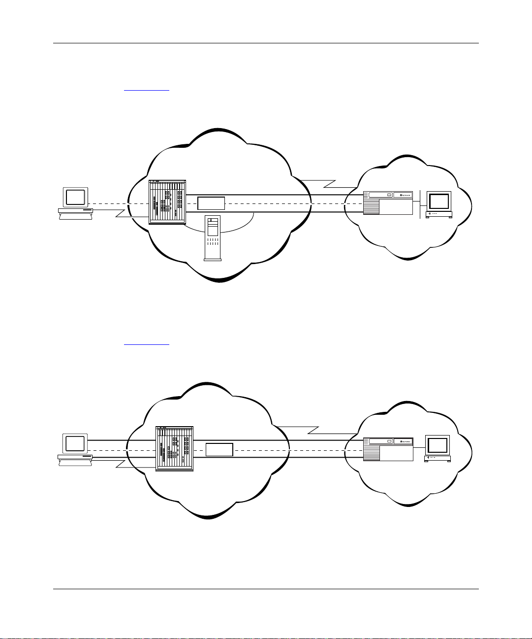
Examples of L2TP Networks
Figure 1-1 shows an L2TP network that uses a LAC to connect to the LNS. The
tunnel is between the LAC and the LNS.
ISP network
L2TP Overview
Remote
host
PC
No L2TP
functionality
PPP
connection
LAC
T unnel
Data
TMS
Figure 1-1. L2TP Network Using a LAC
Figure 1-2 shows an L2TP network that use s a RAS to connect to the LNS. The
tunnel is between the PC (the L2TP client) and the LNS.
ISP network
Remote
host
PC
T unnel
RAS
Data
Frame rela y
connection
Frame rela y
connection
Corporate network
LNS
RADIUS
server
L2T0003A
Corporate network
LNS
L2TP
client
Figure 1-2. L2TP Network Using a RAS
303532-A Rev 00
RADIUS
server
L2T0004A
1-7
Page 24
Configuring L2TP Services
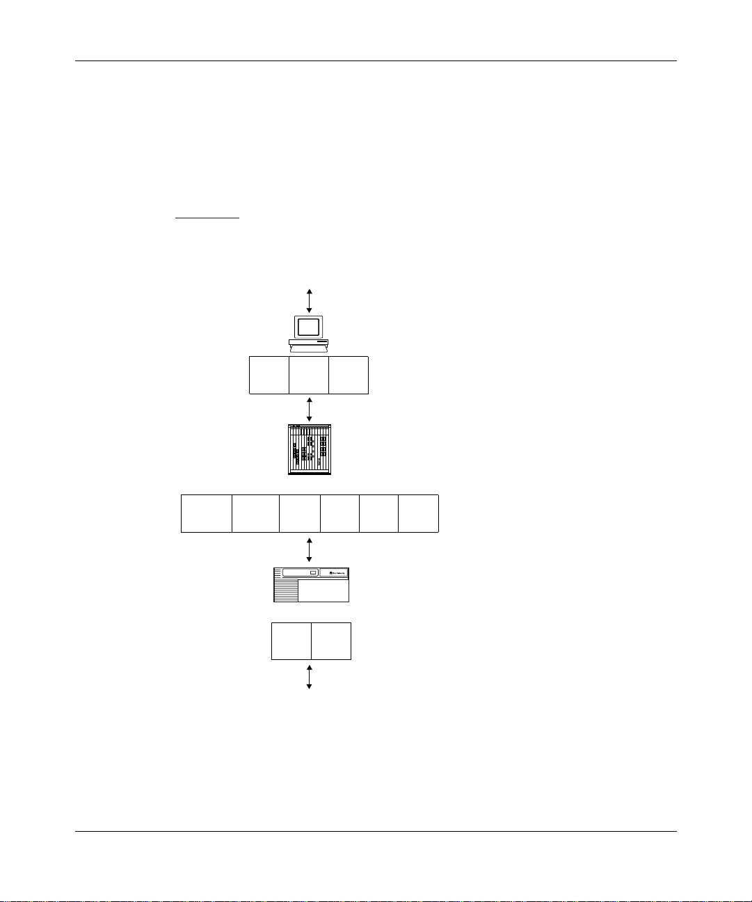
L2TP Packet Encapsulation
The PC or router at the remote site sends PPP packets to the LAC. The LAC
encapsulates thes e incomi ng packets in an L2TP packet and sends it across an IP
network through a bidirectional tunnel. After the LNS receives the packets, it
decapsulates them and terminates the PPP connection.
Figure 1-3
network.
Layer 2
protocol
shows how data is encapsulated for transmission ove r an L2TP
Remote user places a call
PPP IP
IP/UDP
LAC
LNS
DATA
PPP
IPL2TP
DATA
1-8
IP DATA
Data packet moves to the corporate network
L2T0005A
Figure 1-3. Packet Encapsulation Process
303532-A Re v 00
Page 25

Making a Connection Across an L2TP Network
The followin g steps explain how a remote user connects across an L2TP network
that includes a Bay Networks LAC, TMS, and LNS (see Figure 1-1 on page 1-7):
1.
The remote user dials a LAC at the local ISP network to establish a PPP
connection to the corpora te network.
In the call, the user includes any required information, for example, a user
name, including a domain name, and a password. When the user dials in, he
enters a name, for example, jdoe@baynetworks.com; jdoe is the user n ame
and baynetworks.com is the domain name.
2.
The LAC receives the call and passes the domain name to the TMS.
If the TMS finds a match for the domain name, a tunnel can be created. The
TMS also checks the number of current connections so that they will not
exceed the maximum number allowed.
If the user is not a tunnel candidate, as determined by the domain name, the
LAC assumes that the remote host is making a regular dial-in request and
authenticates the user acc ordingly.
L2TP Overview
303532-A Rev 00
3.
The LAC tries to establish an L2TP tunnel with the LNS.
For the LAC to send a tunnel request to the LNS, it needs the address of the
LNS. The LAC requests the address from the TMS. It then checks for this
address in its own routing table. After obtaining the address, the LAC sends a
tunnel request to the LNS. The LNS may perform tunnel authentication, if
configured to do so. If the LAC and LNS complete tunnel authentication
successfully, the LAC establishes the tunnel.
4.
After the tunnel is established, the LAC forwards the remote user’s name to
the LNS, which ver if ies the user’s identity with the corporate RADIUS serv er.
If the RADIUS server recognizes the user name, it replies with an
acknowledgm ent and an IP address that it assigns to the remote user for the
duration of the call. This IP address identifies the remote user who may not
have an addre ss of his own.
5.
After the remote user is succ essfully au thentica ted, the user ha s an end-to- end
PPP connection to the corporate network over the Internet.
The tunnel can now carry a user session dur ing which the LAC and the LNS
exchange PPP packe ts.
1-9
Page 26

Configuring L2TP Services
Security in an L2TP Network
You can configure two layers of security in an L2TP network:
• Tunnel authentication
Tunnel authentication is the process of negotiating the establishment of a
tunnel between the LAC and the LNS.
• User authentication
The network administr ator at the corporate site can configure a RADIUS
server with the names and passwords of authorized users. The server’s
database central izes the authentication function, eli minating the need to
configure each LNS with user names and passwords.
When the LNS receives a call, it forwards the user information to the
RADIUS server, which verifies whet he r the user is authorized to access the
network.
You can also configure the LNS to perform user authentication if a RADIUS
server is not part of the network configuration.
For more information a bout the Bay Networks implementation of tunn el and user
authenticati on, se e “Tunnel Authentication
Authentication” on page 1-14.
” on page 1-12 and “RADIUS User
1-10
303532-A Re v 00
Page 27

Bay Networks L2TP Implementation
In an L2TP network, the Bay Networks router is the LNS. LNS soft ware operates
on the BLN®, BCN®, and ASN™ platforms.
The Bay Networks LNS has the following characteristics:
• Each slot can act as an LNS, which means that one router can ha ve man y LNS
interface s, each with its own address. You can have as man y LNS interfaces as
there are available slots on the router.
• The LNS performs user authentication with a RADIUS server to prevent
unauthorized user s from acce ssing the network.
• The LNS accepts only incoming calls; it does not place calls to the LAC.
• The Bay Networks L2TP implementation supports only IP traffic through the
L2TP tunnel. The LNS supports only numbered IP addresse s.
• The router interface between the ISP and the corporate network (see
Figure 1-1
(including PPP m ultilink) , or ATM. Bay Networks r ecommends t hat you use a
high-speed link, such as T1, for the lea sed connection.
on page 1-7) is a leased line operating with frame relay, PPP
L2TP Overview
303532-A Rev 00
• The LNS terminates PPP multilink and PPP encapsulated data within an
L2TP packet.
• The LNS operates with the LAC implementation configured on the Bay
Networks Model 5399 Remote Access Concentrator.
• The host (PC or router) dialing into the ISP network can be on the same
subnet as the IP inte rface on the LNS.
• The LNS supports RIP. RIP is particularly useful when the remote host is a
router, because it enables the LNS to learn routing information from the
remote router.
For instructions on how to configure a Bay Networks router as an LNS, see
Chapter 2
, “Starting L2TP.”
1-11
Page 28

Configuring L2TP Services
Tunnel Management
The Bay Networks tunnel management server (TMS), which resides at the ISP
network, stores the TMS database. This database contains the remote users’
domain name, the IP address informati on of each LNS, and other tunnel
addressing information that the network administrator configures. The LAC
requests this information from the TMS to construct the L2TP tunnel.
When the LAC receives a call, it forwards the domain na me to the TMS. The
domain name is th e por tion of the use r’s address that s pecif ies a p articul ar l ocation
in the network. For example, if the user name is jdoe@baynetworks. com,
baynetworks.com is the domain name. The TMS looks up the domain name and
verifies that the remote user is an L2TP user. The TMS also provides the LAC
with the addressing information required to establish a tunnel to the correct LNS.
The domain name referred to in this guide is a domain identifier that
Note:
does not foll ow a speci fi c format . It i s not related t o any Domain Na me System
(DNS) protocol requirements.
Tunnel Authentication
1-12
For security purp ose s, you can en able the LNS to perform tunnel authentication.
Tun nel authentication is the process of negotiating the establishment of a tunnel.
During tunnel authenti cation, the LNS identifies the L2TP client or LAC by
comparing the LAC ’s tunnel authentication password with its own password. If
the passwords match, the LNS permit s the LAC to establish a tunnel.
The LAC does not send the tunnel authentication password as a plain-text
message. The exchange of pass words works much like the PPP Challenge
Handshake Authent ication Prot ocol (CHAP). When one side r ecei v es a cha llenge,
it responds with a value that is calculated based on the authentication password.
The receiving side matches the value against its own calculation. If the values
match, authenticat ion is successful.
Tunnel authentication occurs in both directions, which means that the LAC and
LNS both try to verify the other’s identity.
303532-A Re v 00
Page 29

A
L2TP Overview
You can enable tunnel authentication on the Bay Networks LNS. If tunnel
authenticati on is disabled, which is the default, the LNS sends a default challenge
response to the LA C during the authentication process so that the tunne l can be
established. The LNS cannot send outgoing calls, so it cannot initiate tunnel
authentication.
During tunnel authenti cation, the following exchange of messages takes place:
1.
The LAC sends a tunnel setup message, called the start control connection
reque st (SCCRQ) message to the LNS. This message includes a challenge to
the LNS.
2.
The LNS replies with a tunnel response, a chal lenge response, and its own
challenge message. This is called the start control connection reply (SCCRP)
message.
3.
The LAC repli es with a challenge response that includes its tunnel
authentication password. This is the start control connection connected
(SCCCN) message.
4.
If this same password is configured for the LNS, the LNS grants approval to
the LAC to estab lish a tunnel.
303532-A Rev 00
Figure 1-4
shows tunnel authentication.
ISP network
PPP connection
LAC
SCCRQ
tunnel request and challenge
tunnel response, challenge response,
and LNS challenge
SCCCN
challenge response
Figure 1-4. Tunnel Authentication Control Messages
Corporate network
LNS
SCCRP
L2T0006
1-13
Page 30

Configuring L2TP Services
After tunnel authent ication is complete, it does not need to be repeated for other
calls to the same LA C.
RADIUS User Authentication
RADIUS user authentic ation is ena bled b y defa ult on the Bay Netw orks LNS; you
must configur e this feature so that the LNS ca n validate the remote user’s identity
before allowing access to the network.
The network administr ator at the corporate site must configure a RADIUS server
with the names and pas swords of authorized users. When the LNS receives a call,
it forwards an authentic ation request with the user information to the RADIUS
server, which verifies whether the user is authorized. If the user is permitte d
access to the network, the RADIUS serv er replies with an acknowledgment
message and the appropriate IP address f or that user to make a connection.
The IP address that the RADIUS server assigns is essential because many remote
hosts may not have their own addresses. The LNS uses the address to identify the
remote host and send data to the remote user. After the session ends, the IP
address becomes available for another user.
1-14
If the corporate network uses an existing RADIUS database for L2TP
connections, you do not have to reconfigure the names in the databa se . The LNS
automatically r emov es the doma in porti on of t he use r na me that is i ncluded a s part
of the call from the LA C to the LNS. If you want to keep the domain name, you
can disable this feature. For instructions, see Chapter 3
, “Customizing L2TP
Services.”
For more information about configuring Bay Networks routers as RADIUS
servers, see Configuring RADIUS.
303532-A Re v 00
Page 31

RADIUS Accounting
The RADIUS server can provide accounting services in addition to its
authentication services. RADIUS accounting is enabled by default on the Bay
Networks LNS.
The RADIUS accounting serve r calculates billing charges for an L2TP session
between the remote user and the LNS . To determine these charges, the server uses
information that it rec eives from the LNS, such as the status of each call and the
number of packets sent during the ses sion. Using this data, the server determine s
billing charge s, whic h the network administ rator can use to mana ge network costs .
The primary RADIUS accounting server can be the same server as the
authentication server or it can be a different server.
For more information about RADIUS accounting, see Configuring RADIUS.
L2TP IP Interface Addresses
When configuring the Bay Networks LNS, you must configure an IP address for
every slot that has an L2TP interface. This address is referred to as the L2TP IP
interface address. The L2TP IP interface can be any valid IP address .
L2TP Overview
303532-A Rev 00
The L2TP IP interface address is internal to the LNS. When communicating with
the remote user , the LNS associa tes the user’s IP address, which is assigned by the
RADIUS server, with the L2TP IP interface address that you configured.
The L2TP IP interface address and the RA D IUS-assigned IP ad d re ss d o not have
to be in the same subnet.
1-15
Page 32

Configuring L2TP Services
PC 1
PC 2
LAC
192.168.18.41
192.32.25.34
192.32.25.35
Dial-in router
LNS
192.168.19.34
L2TP IP, RIP enabled
192.32.33.94
LAN interface
RIP enabled
192.32.25.33
Dial-on-demand
RIP enabled
Dial-optimized
routing enabled
192.32.25.66
L2T0009B
Remote Router Configuration
If the host at the remote site is a Bay Networks router, you may need to configure
a dial-on-demand circuit for the remote router’s dial-up interface to the LAC at the
ISP network.
Enable RIP on both the dial- on-demand circuit and the attache d LAN interface of
the remote router, so that the LNS can learn routing information from the remote
router. To avoid unnecessarily activating the circ u it beca u s e o f RI P packe t s ,
enable dial-optimized routing for the dial-on-demand circuit (see Figure 1-5
In addition, c onfi gure a de fault or static r oute f or the r emote r outer, which uses the
next-hop address tha t corresponds to the L2TP IP interface addres s of the LN S.
This de f a u l t o r st a t i c ro ute ena b l e s th e remote ro uter to deliver L2TP packets to
the LNS.
).
1-16
Figure 1-5. Remote Router Dialing the LNS
303532-A Re v 00
Page 33

Where to Go Next
Go to one of the following chap ters f or more information:
If you want to Go to
Start L2TP on a router using defa ult parameter settings. Chapter 2
Change default settings for L2TP parameters. Chapter 3
Obtain inf ormation about Site Manager parameters (this is the same
informatio n you obtain using Site Manager online Help).
Review configuration examples. Appendix B
Troubleshoot L2TP configuration problems. Appendix C
L2TP Overview
Appendix A
303532-A Rev 00
1-17
Page 34

Page 35

Chapter 2
Starting L2TP
The quickest way to star t L2TP is to enable it with the default configuration that
Bay Networks software supplies. This configuration uses all available parameter
defaults. You need to supply values f or sev e ral paramet ers that do not hav e default
values.
This chapter includes the following information:
Topic Page
303532-A Rev 00
Planning Considerations for an L2TP Network
Preparing a Configuration File 2-3
Enabling L2TP on an Unconfigured WAN Interface 2-4
Enabling L2TP on an Existing PPP Interface 2-5
Ena bling L2 T P on an Existi n g Frame Rel ay In t e rface 2-7
Enabling L2TP on an Existing ATM Interface 2-9
2-2
2-1
Page 36

Configuring L2TP Services
Planning Considerations for an L2TP Network
This guide primarily e xpla ins how to configure a Bay Networks BLN, BCN, or
ASN router as an LNS in an L2TP network. To successfully operate in an L2TP
network, obtain the following information to conf igure the LNS.
Tunnel Authentication Passwords
If you plan to enable tunnel authentication, which is optional for the Bay
Networks LNS, you must obtain the LAC password from your ISP. For more
information about the authentication process, see “Tunnel Authentication” on
page 1-12.
RADIUS Server Information
The Bay Networks implementation of L2TP requires that you configure a
RADIUS server to perform user authentication and to assign IP addresses to
remote users.
For the RADIUS server, do the following:
2-2
• Configure the RADIUS server with user names and domain names.
• Obtain the address and password of the RADIUS server to enter in the LNS
configura tion.
• Configure the RADIUS server to assign IP addresses to remote users.
This address identi fies the remote user to the LNS during an L2TP sessio n. I f
the remote use r does not have a preconfigured addre ss, the only way to a ssign
addresses is by the RADIUS serv e r. This address is also used for netw ork
communication across the subscriber network.
For more information about configuring Bay Networks routers as RADIUS
servers, see Configuring RADIUS.
303532-A Re v 00
Page 37

Preparing a Configuration File
Before starting L2TP, you must create and save a configurat ion file with at least
one WAN interface, for example, a synchronous or MCT1 port.
L2TP is not compatible with dial serv ices. Do not enable L2TP on the
Note:
same slot that you enable for a dial service, such as dial-on-demand, dial
backup, or bandwidth-on-demand.
For informatio n about the Site Manager configuration tool and how to work with
configura tion files, see Configuring and Managing Routers with Site Manager.
To open the configuration file, complete the following tasks:
Site Manager Procedure
You do this System responds
Starting L2TP
1. In the main Site Manager window, choose
Tools
.
2. Choose
3. Choose
Dynamic
4. Select the file and cl ick on OK. The Configuration Manager window
Configuration Manager
Local File, Remote File
.
. The Configuration Manager window
, or
The Tools menu opens.
opens.
Site Manager prompts you for the
configuration file you want to open.
opens, displaying the router modules.
From the Configurat ion Manager window , go to one of the following sections to
enable L2TP:
Section Page
Enabling L2TP on an Unconfigured WAN Interface
Enabling L2TP on an Existing PPP Interface 2-5
Ena bling L2 T P on an Existi n g Frame Rel ay In t e rface 2-7
Enabling L2TP on an Existing ATM Interface 2-9
2-4
303532-A Rev 00
2-3
Page 38

Configuring L2TP Services
Enabling L2TP on an Unconfigured WAN Interface
To enable L2TP on an unconfigured WAN interface, complete the following tasks:
Site Manager Procedure
You do this System responds
1. In the Configuration M anager window ,
choose a WAN connector.
2. Accept the default circuit name or change
it, then click on OK.
3. Choose
click o n OK.
4. Choose
5. Enter the IP address of the LNS (r outer),
then click on OK.
6. Set the following parameters:
• RADIUS Primary Server IP Address
• RADIUS Primary Server Password
•
7. Click on OK. The L2TP Tunneling Security window
8. Click on OK. The L2TP IP I nter f ace L ist window ope ns ,
9. Set the following parameters:
• L2TP IP Interface Address
•
PPP, Frame Relay
L2TP
, then click on OK. The IP Configuration window opens.
RADIUS Client IP Address
Click on
descriptions beginning on page A-5
Subnet Mask
Help
or see the parameter
, or
ATM
then
The Add Circuit window opens.
The WAN Protocols window opens.
The Select Protocols window opens.
The L2TP Configuration window opens.
.
opens.
followed by the L2TP IP Configuration
window.
Site Manager displays a message
alerting you of the time delay to create
the L2TP tunnel circuits.
2-4
Click on
descriptions beginning on page A-11
10.Click on OK. You return to the L2TP IP Interface List
Help
or see the parameter
.
window, which displays the IP interface
address and the subnet mask. A
message windo w opens that reads,
Configuration is completed
L2TP
.
(continued)
303532-A Re v 00
Page 39

Starting L2TP
Site Manager Procedur e
You do this System responds
11.Click on OK.
12.Click on
Done
. You return to the Configuration Manager
(continued)
window.
Enabling L2TP on an Existing PPP Interface
To enable L2TP on an interface with PPP and IP already enabled, complete the
following ta sks:
Site Manager Procedure
You do this System responds
1. In the Configuration M anager window ,
choose a WAN connector.
2. Choose
3. Choose
the window.
4. Choose
5. Choose
6. Set the following parameters:
• RADIUS Primary Server IP Address
• RADIUS Primary Server Password
•
Edit Circuit
Protocols
Add/Delete
L2TP
RADIUS Client IP Address
. The Circuit Definition window opens.
in the top left corner of
. The Select Protocols window opens.
, then click on OK. The L2TP Configuration window opens.
The Edit Connector window opens.
The Protocols menu opens.
303532-A Rev 00
Click on
descriptions beginning on page A-5
7. Click on OK. The L2TP Tunneling Security window
8. Click on OK. The L2TP IP I nter f ace L ist window ope ns ,
Help
or see the parameter
.
opens.
followed by the L2TP IP Configuration
window.
(continued)
2-5
Page 40

Configuring L2TP Services
Site Manager Procedur e
You do this System responds
9. Set the following parameters:
• L2TP IP Interface Address
• Subnet Mask
Click on
descriptions beginning on page A-11
10.Click on OK. You return to the L2TP IP Interface List
11.Click on OK.
12.Click on
13.Choose
14.Choose
Help
or see the parameter
Done
. You return to the Circuit Definition
File
. The File menu opens.
Exit
. You return to the Configuration Manager
(continued)
Site Manager displays a message
alerting you of the time delay to create
the L2TP tunnel circuits.
.
window, which displays the IP interface
address and the subnet mask. A
message windo w opens that reads,
Configuration is completed
window.
window.
L2TP
.
2-6
303532-A Re v 00
Page 41

Enabling L2 TP on an Existing Frame Relay Interface
T o e nable L2TP on an in terface with frame relay and IP already enabled, complete
the follo wing tasks:
Site Manager Procedure
You do this System responds
Starting L2TP
1. In the Configuration M anager window ,
choose a WAN connector.
2. Choose
3. Choose
4. Choose
the window.
5. Choose
6. Choose
7. Set the following parameters:
• RADIUS Primary Server IP Address
• RADIUS Primary Server Password
•
8. Click on OK. The L2TP Tunneling Security window
9. Click on OK. The L2TP IP I nter f ace L ist window ope ns ,
10.Set the following parameters:
• L2TP IP Interface Address
• Subnet Mask
Edit Circuit
Services
Protocols
Add/Delete
L2TP
RADIUS Client IP Address
Click on
descriptions beginning on page A-5
Help
. The Frame Relay Circuit Definiti on
. The Fr ame Relay Service List window
in the top left corner of
. The Select Protocols window opens.
, then click on OK. The L2TP Configuration window opens.
or see the parameter
The Edit Connector window opens.
window opens.
opens.
The Protocols menu opens.
.
opens.
followed by the L2TP IP Configuration
window.
Site Manager displays a message
alerting you of the time delay to create
the L2TP tunnel circuits.
303532-A Rev 00
Click on
descriptions beginning on page A-11
Help
or see the parameter
.
(continued)
2-7
Page 42

Configuring L2TP Services
Site Manager Procedur e
You do this System responds
11.Click on OK. You return to the L2TP IP Interface List
12.Click on OK.
13.Click on
14.Click on
15.Click on
Done
. You return to the Frame Relay Service
Done
. You return to the Frame Relay Circuit
Done
. You return to the Configuration Manager
(continued)
window, which displays the IP interface
address and the subnet mask. A
message windo w opens that reads,
Configuration is completed
List window.
Definition win dow.
window.
L2TP
.
2-8
303532-A Re v 00
Page 43

Enabling L2TP on an Existing ATM Interface
T o enabl e L2TP on an interface with ATM and IP already enabled, you can enable
L2TP in two ways. If your interface uses a COM connector, complete the tasks in
the follo wing table. If your interface uses an ATM connector, go to page 2-10.
Site Manager Procedure
You do this System responds
Starting L2TP
1. In the Configuration M anager window ,
choose a WAN connector.
2. Choose
3. Choose
4. Choose
5. Choose
6. Set the following parameters:
• RADIUS Primary Server IP Address
• RADIUS Primary Server Password
•
7. Click on OK. The L2TP Tunneling Security window
8. Click on OK. The L2TP IP I nter f ace L ist window ope ns ,
9. Set the following parameters:
• L2TP IP Interface Address
• Subnet Mask
10.Click on OK. You return to the L2TP IP Interface List
11.Click on OK.
Edit Circuit
Group Protocols
Add/Delete
L2TP
RADIUS Client IP Address
Click on
descriptions beginning on page A-5
Click on
descriptions beginning on page A-11
Help
Help
. The Circuit Definition window opens.
. The Group Protocols menu opens.
. The Select Protocols window opens.
, then click on OK. The L2TP Configuration window opens.
or see the parameter
or see the parameter
The Edit Connector window opens.
.
opens.
followed by the L2TP IP Configuration
window.
Site Manager displays a message
alerting you of the time delay to create
the L2TP tunnel circuits.
.
window, which displays the IP interface
address and the subnet mask. A
message windo w opens that reads,
Configuration is completed
L2TP
.
(continued)
303532-A Rev 00
2-9
Page 44

Configuring L2TP Services
Site Manager Procedur e
You do this System responds
12.Click on
13.Choose
14.Choose
Done
. You return to the Circuit Definition
File
. The File menu opens.
Exit
. You return to the Configuration Manager
(continued)
window.
window.
If your ATM interface uses an ATM connector, complete the following tasks:
Site Manager Procedure
You do this System responds
1. In the Configuration M anager window ,
choose an ATM connector.
2. Choose
3. Choose
4. Choose
5. Choose
6. Complete steps 6
previous table.
7. Click on
8. Click on
9. Click on
Service Attributes
Proto cols
Add/Delete.
L2TP
Done
Done
Done
. The Protocols menu opens.
, then click on OK. The L2TP Configuration window opens.
through 11 in the
. You return to the ATM Servic e Re c o rd s
. You return to the E d it ATM Connecto r
. You return to the Configuration Manager
. The ATM Service Records List window
The Edit ATM Connector window opens.
opens.
The Select Protocols window opens.
Site Manager enables L2TP.
List window.
window.
window.
2-10
303532-A Re v 00
Page 45

Chapter 3
Customizing L2TP Services
When you enable L2TP, default values are in effect for most parameters (see
parameter descrip tions in Appendix A, “L2TP Paramete rs”). You may want to
change some of these values, depending on the requirements of your network.
This chapter includes the following information:
Topic Page
Modifying the L2TP Protocol Configuration
Modifying RADIUS Server Information 3-3
Changing the LNS System Name 3-4
Modifying the Number of L2TP Sessions Permitted 3-5
Keeping the Remote User’s Domain Name 3-6
Changing the Domain Name Delimiter 3-7
Enabling Tunnel Authentication 3-8
Modifying L2TP IP Interface Addresses 3-9
Disabling RIP 3-10
Disabling L2TP 3-10
Deleting L2TP from a PPP Interface 3-11
Deleting L2TP from a F rame Relay Interface 3-12
Deleting L2TP from an ATM Interface 3-13
3-2
303532-A Rev 00
3-1
Page 46

Configuring L2TP Services
Modifying the L2TP Protocol Configuration
To modify how data is transmitte d acr oss an L2TP network, such as the number,
frequency, and timing of data and acknowledgment packets exchanged between
the LNS and LAC, you can modify the L2TP protocol pa rameters.
To modify the L2TP protocol confi guration, complete the following tasks:
Site Manager Procedure
You do this System responds
1. In the Configuration M anager window ,
choose
2. Choose
3. Choose
4. Choose
5. Select an LNS entry from the list.
6. Edit any of the following parameters:
• Receive Window Size
• Retransmit Timer (seco nds)
• Maximum Retransmit
• Hello Timer (seconds)
• Ack Timeout (milliseconds)
•
7. Click on
Protocols
IP
. The IP menu opens.
L2TP
L2TP Configuration
T unnel Flow Control
Click on
descriptions beginning on page A-3
Done
.
. The L2TP menu opens.
. The L2TP Configuration List window
Help
or see the parameter
. You return to the Configuration Manager
The Protocols menu opens.
opens.
.
window.
3-2
303532-A Re v 00
Page 47

Modifying RADIUS Server Information
If you change the address of the RADIUS serve r tha t you are usin g to authentic ate
remote users and manage accounting functions, you must update the server
address information on the LNS.
For more information about using a RADIUS server in an L2TP network, see
“RADIUS Se rver
To modify the address of the RADIUS server, complete the follo wing tasks:
You do this System responds
” on page 1-6.
Site Manager Procedure
Customizing L2TP Services
1. In the Configuration M anager window ,
choose
2. Choose
3. Choose
4. Choose
5. Select an LNS entry from the list.
6. Set the following parameters:
• RADIUS Primary Server IP Address
• RADIUS Primary Server Password
•
7. Click on
Protocols
IP
. The IP menu opens.
L2TP
L2TP Configuration
RADIUS Client IP Address
Click on
descriptions beginning on page A-5
Done
.
. The L2TP menu opens.
. The L2TP Configuration List window
Help
or see the parameter
. You return to the Configuration Manager
The Protocols menu opens.
opens.
.
window.
You can also modify the RADIUS information in the conf iguration windows
specific to RADIUS. For more information, see Configuring RADIUS.
303532-A Rev 00
3-3
Page 48

Configuring L2TP Services
Changing the LNS System Name
The LNS system name is the name of the router. This name is used during tunnel
setup to identify the LNS uniquely.
By default, Site Manager enters the system name that you initially configured
when first accessing the router. See Configuring and Managing Routers with Site
Manager f or more det ails about system information.
To change the LNS system name, complete the following tasks:
Site Manager Procedure
You do this System responds
1. In the Configuration M anager window ,
choose
2. Choose
3. Choose
4. Choose
5. Select an LNS entry from the list.
6. Set the
Click on
description on page A-5
7. Click on
Protocols
IP
. The IP menu opens.
L2TP
L2TP Configuration
LNS System Name
Help
Done
.
. The L2TP menu opens.
. The L2TP Configuration List window
parameter.
or see the parameter
.
. You return to the Configuration Manager
The Protocols menu opens.
opens.
window.
3-4
303532-A Re v 00
Page 49

Customizing L2TP Services
Modifying the Number of L2TP Sessions Permitted
You can modify the maximum number of active L2TP sessions that the LNS can
manage. The default is 100 sessions.
For more information about L2TP sessions, see “L2TP Sessions
” on page 1-3.
To change the maximum number of L2TP sessions supported by the LNS,
complete the follo wing tasks:
Site Manager Procedure
You do this System responds
1. In the Configuration M anager window ,
choose
2. Choose
3. Choose
4. Choose
5. Select an LNS entry from the list.
6. Set the
Click on
description on page A-3
7. Click on
Protocols
IP
. The IP menu opens.
L2TP
L2TP Configuration
Max L2TP Sessions
Help
Done
.
. The L2TP menu opens.
. The L2TP Configuration List window
parameter.
or see the parameter
.
. You return to the Configuration Manager
The Protocols menu opens.
opens.
window.
303532-A Rev 00
3-5
Page 50

Configuring L2TP Services
Keeping the Remote User’s Domain Name
The LNS removes the domain name from the complete user name by default,
before passing it on to the RADIUS serve r for user authentication.
To keep the domain name with the user name, complete the following tasks:
Site Manager Procedure
You do this System responds
1. In the Configuration M anager window ,
choose
2. Choose
3. Choose
4. Choose
5. Select an LNS entry from the list.
6. Set the
parameter to
see the parameter description on
page A-7
7. Click on
Protocols
IP
. The IP menu opens.
L2TP
L2TP Configuration
Remove Domain Name
.
Done
.
. The L2TP menu opens.
. The L2TP Configuration List window
Disable
. Click on
. You return to the Configuration Manager
Help
or
The Protocols menu opens.
opens.
window.
3-6
303532-A Re v 00
Page 51

Changing the Domain Name Delimiter
In the complete user name there is a single-character delimiter that separat es the
user name from t he domain name. By default, the LNS removes the domain name
when it receives a call. The delimiter tells the LNS which characters to remove.
The default delimit er is an at sign (@).
To change the delimiter, complete the following tasks:
Site Manager Procedure
You do this System responds
Customizing L2TP Services
1. In the Configuration M anager window ,
choose
2. Choose
3. Choose
4. Choose
5. Select an LNS entry from the list.
6. Set the
parameter. Click on
parameter descri pti on on pageA-7
7. Click on
Protocols
IP
. The IP menu opens.
L2TP
L2TP Configuration
Domain Name Delimiter
Done
.
. The L2TP menu opens.
. The L2TP Configuration List window
Help
or see the
.
. You return to the Configuration Manager
The Protocols menu opens.
opens.
window.
303532-A Rev 00
3-7
Page 52

Configuring L2TP Services
Enabling T unnel Authentication
To prevent una uthorized users from accessing the corporate network, you can
enable tunnel authentication. During tunnel negotiation, the LAC sends its tunnel
authentication password to the LNS. If the password is not recognized by the
LNS, authentication is unsuccessful and the LAC cannot create the tunnel.
If you are using the Password Authentication Protocol (PAP) for PPP
Note:
authenticati on, do not en abl e tunnel authentication.
For more in format ion abou t t unnel authe nti cation, see “T unnel Aut hentic ation
page 1-12.
To enable tunnel authentica tion, complete the following tasks:
Site Manager Procedure
You do this System responds
1. In the Configuration M anager window ,
choose
2. Choose
3. Choose
4. Choose
5. Select an LNS entry from the list.
6. Set the following parameters:
• Enable Tunnel Authentication
•
7. Click on
Protocols
IP
. The IP menu opens.
L2TP
Tunnel Authentication
T unnel Authentica tion Password
Click on
descriptions on page A-9
Done
.
. The L2TP menu opens.
. The L2TP Tunnel Security Li st window
Help
or see the parameter
.
. You return to the Configuration Manager
The Protocols menu opens.
opens.
window.
” on
3-8
303532-A Re v 00
Page 53

Modifying L2TP IP Interface Addresses
The L2TP IP Interface List window lists the L2TP IP interface addresses for each
slot that has L2TP configur ed. The LNS uses the addresses internally to identify
the remote sites.
For more information about the L2TP IP interface, see “L2TP IP Interface
Addresses” on page 1-16.
To change an address on the list, complete the following tasks:
Site Manager Procedure
You do this System responds
Customizing L2TP Services
1. In the Configuration M anager window ,
choose
2. Choose
3. Choose
4. Choose
5. Select an LNS entry from the list.
6. Click on
7. Modify the following parameters:
• L2TP IP Interface Address
• Subnet Mask
8. Click on OK. You return to the L2TP IP Interface List
9. Click on
Protocols
IP
. The IP menu opens.
L2TP
L2TP IP Interface
Change
Click on
descriptions beginning on page A-11
Done
.
. The L2TP menu opens.
. The L2TP IP Interface List window opens.
. The L2TP IP Interface window opens.
Help
or see the parameter
. You return to the Configuration Manager
The Protocols menu opens.
.
window. The new address appears in the
list.
window.
303532-A Rev 00
3-9
Page 54

Configuring L2TP Services
Disabling RIP
RIP is enabled on the LNS by default so that the LNS can learn routes from the
remote dial-in router. If the LNS does not require RIP support, you can disable it.
To disable RIP, complete the following tasks:
You do this System responds
Site Manager Procedure
1. In the Configuration M anager window ,
choose
2. Choose
3. Choose
4. Choose
5. Select an LNS entry from the list.
6. Set the
Click on
description on page A-12
7. Click on
Disabling L2TP
To disable L2TP on a slot, complete the following tasks:
You do this System responds
1. In the Configuration M anager window ,
choose
2. Choose IP. The IP menu opens.
3. Choose
4. Choose
5. Select an LNS entry from the list.
The Protocols menu opens.
Protocols
IP
. The IP menu opens.
L2TP
L2TP IP Interface
RIP Enable
Help
Done
Protocols
L2TP
L2TP Configuration
.
. The L2TP menu opens.
. The L2TP IP Interface List window opens.
para m e ter to
or see the parameter
.
. You return to the Configuration Manager
.
. The L2TP menu opens.
Disable
Site Manager Procedure
. The L2TP Configuration List window
.
window.
The Protocols menu opens.
opens.
(continued)
3-10
303532-A Re v 00
Page 55

Customizing L2TP Services
Site Manager Procedur e
You do this System responds
6. Set the
Disable
parameter descri pti on on pageA-3
7. Click on
Enable L2TP
. Click on
Done
parameter to
Help
or see the
. You return to the Configuration Manager
.
Deleting L2TP from a PPP Interface
To delete L2TP from a PPP interface, complete the following tasks:
Site Manager Procedure
You do this System responds
1. In the Configuration M anager window ,
click on a WAN connector configured with
L2TP.
2. Choose
3. Choose
4. Choose
5. Click on
6. Click on OK. You return to the Circuit Definition
7. Choose
8. Choose
Edit Circuit
Protocols
Add/Delete
L2TP
File
. The File menu opens.
Exit
. You return to the Configuration Manager
. The Circuit Definition window opens.
. The Protocols menu opens.
. The Select Protocols window opens.
. Site Manager deselects L2TP.
(continued)
Site Manager disables L2TP for the slot.
window.
The Edit Connector window opens.
window.
window.
303532-A Rev 00
3-11
Page 56

Configuring L2TP Services
Deleting L2TP from a Frame Relay Interface
To delete L2TP from a frame relay interface, complete the following tasks:
Site Manager Procedure
You do this System responds
1. In the Configuration M anager window ,
click on a WAN connector configured with
L2TP.
2. Choose
3. Choose
4. Choose
the window.
5. Choose
6. Click on
7. Click on OK. You return to the Frame Relay Service
8. Click on
9. Click on
Edit Circuit
Services
Protocols
Add/Delete
L2TP
Done
Done
. The Frame Relay Circuit Definiti on
. The Fr ame Relay Service List window
in the top left corner of
. The Select Protocols window opens.
. Site Manager deselects L2TP.
. You return to the Frame Relay Circuit
. You return to the Configuration Manager
The Edit Connector window opens.
window opens.
opens.
The Protocols menu opens.
List window.
Definition win dow.
window.
3-12
303532-A Re v 00
Page 57

Deleting L2TP from an ATM Interface
To delete L2TP from an ATM interface on a COM connector, complete the
following ta sks:
Site Manager Procedure
You do this System responds
Customizing L2TP Services
1. In the Configuration M anager window ,
click on a COM connector configured with
L2TP.
2. Choose
3. Choose
4. Choose
5. Click on
6. Click on OK. You return to the Circuit Definition
7. Choose
8. Choose
Edit Circuit
Group Protocols
Add/Delete
L2TP
File
. The File menu opens.
Exit
. You return to the Configuration Manager
. The Circuit Definition window opens.
. The Group Protocols menu opens.
. The Select Protocols window opens.
. Site Manager deselects L2TP.
The Edit Connector window opens.
window.
window.
To delete L2TP from an ATM interface on an ATM connector, complete the
following ta sks:
Site Manager Procedure
You do this System responds
1. In the Configuration M anager window ,
click on an ATM connector configured with
L2TP.
2. Choose
3. Choose
the window.
4. Choose
5. Click on
Service Attributes
Protocols
Add/Delete
L2TP
in the top left corner of
. The Select Protocols window opens.
. Site Manager deselects L2TP.
. The ATM Service Records List window
The Edit ATM Connector window opens.
opens.
The Protocols menu opens.
(continued)
303532-A Rev 00
3-13
Page 58

Configuring L2TP Services
Site Manager Procedur e
You do this System responds
6. Click on OK. You return to the ATM Servic e Re c o rd s
7. Click on
8. Click on
Done
. You return to the E d it ATM Connecto r
Done
. You return to the Configuration Manager
(continued)
List window.
window.
window.
3-14
303532-A Re v 00
Page 59

Appendix A
L2TP Parameters
This appendix contains the Site Manage r parameter descriptions for L2TP
services. You can display the same information using Site Manager online Help.
For information about the IP parameters that you set when enabling L2TP, see
Configuring I P Services.
This appendix contains the following information:
T opic Page
303532-A Rev 00
L2TP Configuration Parameters
L2TP Tunnel Security Parameters A-8
L2TP IP Interface Parameters A-10
For each parameter, this appendix provi des the following information:
• Parameter name
• Configuration Manager menu path
• Default setting
• Valid parameter options
• Parameter function
• Instructions for setting the parameter
• Management information base (MIB) object ID
A-2
A-1
Page 60

Configuring L2TP Services
The Technician Interface allows you to modify parameters by issuing
commit
commands with the MIB object ID. This process is equivalent to
modifying parameters using Site Manager. F or more inf ormation about using the
T echnician Interface to access the MIB, see Using Technician Interface Software.
Caution:
The Technician Interface does not verify parameter values you enter.
Entering an invalid value can corrupt your configuration.
L2TP Configuration Parameters
The L2TP Configurati on List window (Figure A-1) contains parameters that
define how L2TP sends and receives dat a .
set
and
A-2
Figure A-1. L2TP Configuration List Window
The parameter descriptions follow.
303532-A Re v 00
Page 61

L2TP Parameters
Parameter: Enable L2TP
Path: Configuration Manager > Protocols > IP > L2TP > L2TP Configuration
Default: Enable
Options: Enable
|
Disable
Function: Enables or disables L2TP on this interface.
Instructions: Si te Manager automatica lly sets thi s paramete r to Enable when you selec t L2TP
as a protocol. Accept the default , Ena ble, to use L2TP. To temporarily disable
L2TP, set this parameter to Disable.
MIB Object ID: 1.3.6.1.4 .1.18.3.5.23.2.1.2
Parameter: Max L2TP Sessions
Path: Configuration Manager > Protocols > IP > L2TP > L2TP Configuration
Default: 100
Options: 1 to 100 sessions
Function: Specifies the maximum number of L2TP sessions that the LNS allows.
Instructions: Ente r the maximum number of L2TP sessions that you wa nt the LNS to support.
MIB Object ID: 1.3.6.1.4 .1.18.3.5.23.2.1.16
Parameter : Receive Window Size
Path: Configuration Manager > Protocols > IP > L2TP > L2TP Configuration
Default: 4
Options: 1 to 7 packets
Function: Specifies the number of control pack ets that the LNS can receive from the LAC
without the LNS sending an acknowledgment packet to the LAC.
Instructions: Enter the number of packets that determine the window size, or accept the
default va lue.
MIB Object ID: 1.3.6.1.4 .1.18.3.5.23.2.1.6
303532-A Rev 00
A-3
Page 62

Configuring L2TP Services
Parameter : Retransm it Time r (s econ ds )
Path: Configuration Manager > Protocols > IP > L2TP > L2TP Configuration
Default: 1
Options: 1 to 60 seconds
Function: Indicates the number of seconds that the LNS waits for an acknowledgment
from the LAC before resending packets.
Instructions: If you are experiencing many timeouts during L2TP tunnel negotiation or
during a session, set this value to a number greater than the default. Otherwise,
accept the default.
MIB Object ID: 1.3.6.1.4 .1.18.3.5.23.2.1.7
Parameter: Maximum Retransmit
Path: Configuration Manager > Protocols > IP > L2TP > L2TP Configuration
Default: 1
Options: 1 to 60
Function: Specifies the maximum number of times the LNS retransmits packets to the
LAC.
Instructions: If you are experiencing many timeouts during L2TP tunnel negotiation or
during a session, set this value to a number greater than the default. Otherwise,
accept the default.
MIB Object ID: 1.3.6.1.4 .1.18.3.5.23.2.1.8
Parameter: Hello Timer (seconds)
Path: Configuration Manager > Protocols > IP > L2TP > L2TP Configuration
Default: 60
Options: 1 to 60 seconds
Function: Indicates t he maximum number of seconds that can elapse with out data activity
before the LNS sends a packet through the tunnel to the LAC to check the
connection.
Instructions: Set this parameter to a smaller number only if the connection is not stable .
Otherwise, accept the defa ult.
MIB Object ID: 1.3.6.1.4 .1.18.3.5.23.2.1.9
A-4
303532-A Re v 00
Page 63

L2TP Parameters
Parameter: Ack Timeout (milliseconds)
Path: Configuration Manager > Protocols > IP > L2TP > L2TP Configuration
Default: 250
Options: 1 to 350 milliseconds
Function: Specifies the maximum number of milliseconds that can elapse before the LNS
sends an acknowledgm ent to the LA C th at it recei v ed an L2TP contr ol message,
such as a tunnel authentication or session control message.
Instructions: If you are unsure of the stability of the connection or the L2TP session, se t this
parameter to a number smaller than the default. Otherwise, accept the default.
MIB Object ID: 1.3.6.1.4 .1.18.3.5.23.2.1.10
Parameter: LNS System Name
Path: Configuration Manager > Protocols > IP > L2TP > L2TP Configuration
Default: BayRS
Options: The router’s system name or any name you specify
Function: Specifies the name of the LNS. This name applies to the router, not just the slot
with the LNS interface.
Instructions: Site Manager automatically enters the name from the router’s system
information. You can modify it, if you choose. If no system name is provided,
the router uses BayRS.
MIB Object ID: 1.3.6.1.4 .1.18.3.5.23.2.1.12
Parameter: RADIUS Primary Serv er IP Address
Path: Configuration Manager > Protocols > IP > L2TP > L2TP Configuration
Default: None
Options: Any 32-bit IP address
Function: Specifies the primary RADIUS server for user authentication.
Instructions: Enter the IP address of the RADIUS server. If the RADIUS server is already
configured, Site Manager automatically supplies the address.
MIB Object ID: 1.3.6.1.4 .1.18.3.5.22.2.1.3
303532-A Rev 00
A-5
Page 64

Configuring L2TP Services
Parameter: RADIUS Primary Serv er Password
Path: Configuration Manager > Protocols > IP > L2TP > L2TP Configuration
Default: None
Options: Any alphanumeric string, up to a maximum of 64 characters
Function: Specifies the primary RADIUS server’s password.
Instructions: Enter the password for the RADIUS server. If the RADIUS server is already
configured, Site Manager automatically supplies the passw ord.
MIB Object ID: 1.3.6.1.4.1.18.3.5.22.2.1.11
Parameter: RADIUS Client IP Address
Path: Configuration Manager > Protocols > IP > L2TP > L2TP Configuration
Default: None
Options: Any IP address
Function: Identifies the router acting as the LNS. This address applies for the en tire router .
Instructions: Enter the IP address of the router. If the RADIUS server is already configured,
Site Manager automaticall y supplie s the address.
MIB Object ID: 1.3.6.1.4 .1.18.3.5.22.1.1.5
Parameter: Tunnel Flow Control
Path: Configuration Manager > Protocols > IP > L2TP > L2TP Configuration
Default: Disable
|
Options: Enable
Disable
Function: Specif ies whether the LNS uses flow control on the tunnele d data packet s. Flo w
control ensures the stable flow of data between both sides of the connection.
Instructions: To enable flow control, select Enable . Othe rwi se, accept the default, Disable.
MIB Object ID: 1.3.6.1.4 .1.18.3.5.23.2.1.20
A-6
303532-A Re v 00
Page 65

L2TP Parameters
Parameter: Remove Domain Name
Path: Configuration Manager > Protocols > IP > L2TP > L2TP Configuration
Default: Enable
Options: Enable
|
Disable
Function: Instructs the router whether to re move the domain name from the complete user
name before RADIUS authentication takes place. If enabled, the LNS removes
the delimiter separating the use r name and the domain name and all characters
to the right of the delimiter. Removing the domain name ensures that the
RADIUS server c an identi fy the user without ha ving t o r econf i gure the names i n
the server database.
Instructions: Accept the default, Enable, to remove the domain name from the user name.
Select Disable to keep the domain name.
MIB Object ID: 1.3.6.1.4 .1.18.3.5.23.2.1.21
Parameter: Domain Name Delimiter
Path: Configuration Manager > Protocols > IP > L2TP > L2TP Configuration
Default: @
Options: A single-charact er string (for example, a colon)
Function: This character ide ntifies the delimiter used to separ ate the domain name from
the user name. This parameter is relevant only if you accept the default value,
Enable, for the Remove Domain Name paramet er.
Instructions: Specify a character as a delimit er or accep t the defa ult.
MIB Object ID: 1.3.6.1.4 .1.18.3.5.23.2.1.22
303532-A Rev 00
A-7
Page 66

Configuring L2TP Services
L2TP Tunne l Securi ty Parameters
The L2TP Tunnel Sec urity List window (Figure A-2) contains the tunnel
authentication parameters.
A-8
Figure A-2. L2TP Tunnel Sec uri t y Lis t Wi nd ow
The parameter descriptions follow.
303532-A Re v 00
Page 67

L2TP Parameters
Parameter: Enable Tunnel Authentication
Path: Configuration Manager > Protocols > IP > L2TP > Tunnel Authentication
Default: Disable
|
Options: Enable
Disable
Function: Enables or disables the use of tunnel authentication for a slot on the LNS.
Tunnel aut hentication provides a le vel of network security to protect the
corporate network from unauthorized users.
Instructions: Set this parameter to Enable for the LNS to perform tunnel authentication.
Otherwise, accept the default, Disable.
MIB Object ID: 1.3.6.1.4 .1.18.3.5.23.1.1.2
Parameter: Tunnel Authentication Password
Path: Configuration Manager > Protocols > IP > L2TP > Tunnel Authentication
Default: None
Options: An alphanumeric string, up to a maximum of 40 characters
Function: Identif ies the L NS to the LAC if the de vices are u sing tunnel authentic ation. The
LAC and the LNS must share the same password to successfully complete
tunnel authentication.
Instructions: Enter a password.
MIB Object ID: 1.3.6.1.4 .1.18.3.5.23.1.1.5
303532-A Rev 00
A-9
Page 68

Configuring L2TP Services
L2TP IP Interface Parameters
The L2TP IP Interface List window (Figure A-3) contains the list of IP interfaces
for each slot on the router configured with L2TP.
A-10
Figure A-3. L2TP IP Interface List Window
When you click on Change , S ite Manager displays the L2TP IP Interface window
(Figure A-4).
Figure A-4. L2TP IP Interface W in dow
303532-A Re v 00
Page 69

L2TP Parameters
The parameter descriptions follow.
Parameter : L 2 TP IP I nte rfa ce Ad dres s
Path: Configuration Manager > Protocols > IP > L2TP > L2TP IP Interface
Default: None
Options: Any unique IP address
Function: Specifies the IP address that identifi es the L2TP IP interface for the LNS. You
must provide an address for each slot configured as an LNS.
Instructions: Enter a unique IP address. This address applies for the entire router slot.
MIB Object ID: Not Applicable
Parameter: Subnet Mask
Path: Configuration Manager > Protocols > IP > L2TP > L2TP IP Interface
Default: None
Options: A 32-bit IP subnet mask
Function: Specifies the network and subnet portion of the L2TP IP interface address.
Site Manager automaticall y calc ulates a natural subnet mask based on the class
of the network address. For example, if you enter a Class C address, the subnet
mask will be 255.255.255.0.
To configure more subnets for your network, you can change this natural mask.
Instructions: Accept the assigned natural subnet mask or enter a new one. You are not
restricted to entering a natural mask. For example, if the L2TP IP address is
192.32.16.55, you can enter a subnet mask of 255.255.255.192.
MIB Object ID: 1.3.6.1.4 .1.18.3.5.3.2.1.24.1.6
303532-A Rev 00
A-11
Page 70

Configuring L2TP Services
Parameter: RIP Enable
Path: Configuration Manager > Protocols > IP > L2TP > L2TP IP Interface
Default: Enable
Options: Enable
|
Disable
Function: Specifies whether RIP Listen is enabled on this interface. See Configuring IP
Services for more information about RIP.
Instructions: Accept the default, Enabl e, so th at the LNS ca n learn routes from a remote
dial-in router. Select Disable to disable RIP.
MIB Object ID: 1.3.6.1.4 .1.18.3.5.3.2.2.2.1.2
A-12
303532-A Re v 00
Page 71

Appendix B
Configuration Examples
This appendix prov ides tw o e xample s of L2TP networ k config urati ons. It i ncludes
only those parameters that require changes from their default settings for proper
configura tion. For instructions on modifying pa ramete rs, see Chapter 3,
“Customizing L2TP Services.”
This appendix assumes that you are familiar with L2TP configuration proc ed ures.
For information about setting up an interface on the router, see Quick-Starting
Routers and Configuring and Managing Routers with Site Manager.
Example 1: Remote PC Calling the Corporate Network
Figure B-1 shows a sample L2TP network. In this network, note the following:
• Domain names are in the TMS database.
• User names and domain names are in the RADIUS server database.
• Tunnel IP interface addresses are unique for each slot.
• Frame relay is the WAN protocol for t he connection between the I SP network
and the corporate network.
303532-A Rev 00
B-1
Page 72

Configuring L2TP Services
No active call from mmark;
no tunnel needed
mmark@baynetworks.com
PC
No L2TP
functionality
jsmart@baynetworks.com
PC
No L2TP
functionality
Modem
TA
ISDN
Multilink
PPP
ISP network
LAC 2
TMS
LAC 1
Domain name in TMS database
baynetworks.com = 192.32.16.55
Frame rela y
T unnel
Corporate
network
LNS
192.32.16.55
192.32.68.2
L2TP IP
interface
IP addresses in the
RADIUS server database
192.32.40.1 jsmart@baynetworks.com
192.32.40.2 mmark@baynetworks.com
Router
.17
RADIUS server
192.32.26.6
bay_private
.26.0
L2T0007B
Figure B-1. L2TP Network with PCs at the Remote Site
Configuring the Remote Hosts
The remote hosts in this network are two PCs running Windows 95. Neither PC
has internal L2TP capabil ities.
In this network, one PC has a synchronous dial connection to the ISP via a
modem. The other PC has a 128 Kb/s dial ISDN connection through an ISDN
terminal adap t er (TA).
The user names at the PCs are mmark@baynetworks.c om and
jsmart@baynetwor ks.com.
B-2
303532-A Re v 00
Page 73

Configuring the LACs and the TMS
The LACs in this network are Model 5399 Remote Access Concentrators. Both
devices ha ve L2TP modules installed. See Model 5399 Remote Access
Concentrator documenta tion for information about configuring L2TP.
The LACs use the same TMS, which you configure with the following
information:
Domain name: baynetworks.com
Tunnel end point address (LNS address): 192.32.16.55
Tunnel authentication password: LAC1
Configuring the LNS
The LNS in this network is a BN router with at least two synchronous interfaces.
To configure the router as an LNS:
Choose a WAN port for the slot y ou want as the LNS.
1.
From the WAN Protocols menu, choose Frame Relay.
2.
Configuration Examples
303532-A Rev 00
From the Select Pr otocols menu, choose IP and L2TP.
3.
In the IP Configuration window, enter the IP address of the LNS.
4.
Paramet e r Name Value
IP Address 192.32.16.55
In the L2TP Configuration window, enter the RADIUS server
5.
informati on.
Paramet e r Name Value
RADIUS Primary Server IP Address 192.32.26.6
RADIUS Primary Server Password bay_private
RADIUS Client IP Address 192.32.16.55
B-3
Page 74

Configuring L2TP Services
In the L2TP Tunneling Security window, enable tunnel authentication.
6.
Paramet e r Name Value
Enable Tunnel Authentication Enable
Tunnel Authentication Password LAC1
In the L2TP IP Interface window, enter the L2TP IP address.
7.
Paramet e r Name Value
L2TP IP Interf ace Address 192.32.68.2
Subnet Mask 255.255.255.0
During the L2TP session, the RADIUS server assigns the following IP
addresses:
jsmart@baynetwor ks.com: 192.32.40.1
mmark@baynetworks.com: 192.32.40.2
These addresses are stor ed in the RADIUS serv er database.
Data Path Through the Network
After all components of the netw ork are configured, jsmart can place a call to the
local ISP. The LAC that receiv es this call sends the user name to the TMS, which
verifies the domain name and address and sends this information back to the LAC
so that it can forward the data.
The LAC then ne gotiates the initiation of the tunnel with the LNS, and the tunnel
is brought up. The LNS then authenticates jsmart@baynetworks.com with the
RADIUS server. After the RADIUS server grants access, it assigns the address
192.32.40.1 to jsmart, to inc lude the remote host (jsmart’s PC) in the virtual
private network.
Data now passes through the tunnel from jsmart’s PC to the LNS for the duration
of the L2TP session. When jsmart disconnects the call, the session is terminated.
If no other active sessions are using the tunnel, the tunnel is brought down.
B-4
303532-A Re v 00
Page 75

Configuration Examples
Example 2: Remote Router Calling the Corporate Network
Figure B-2 shows a network with two BayStack™ AN® routers at the r emote site.
The AN routers are us ing dial-o n -demand servi ce fo r dia l- up connections.
In this network, note the following:
• PPP is the WAN protocol for the conne ction between the ISP ne twork and the
corporate network.
• For the LNS configuration, you do not need to configure a static route for the
remote router’s network because the LNS can learn the rout e using RIP.
• The IP network addresses are assigned as follows:
jsmart@bay.com: 192.32.40.1
mmark@bay.com: 192.32.40.2
No active call from mmark;
PC
PC
no tunnel needed
mmark@bay .com
No L2TP
functionality
jsmart@bay .com
No L2TP
functionality
Modem
TA
ISDN
Multilink
PPP
ISP network
LAC 2
TMS
LAC 1
Domain name in TMS database
bay .com = 192.32.16.55
LNS
192.32.16.55
PPP
T unnel
192.32.40.254
L2TP IP
interface
IP addresses in the
RADIUS server database
192.32.40.1 jsmart@bay .com
192.32.40.2 mmark@bay .com
Corporate
network
.17
RADIUS server
192.32.26.6
bay_private
Router
.26.0
L2T0008B
Figure B-2 . L2TP Network with Rout ers at the R em ote Site
The LNS configurat ion in this e xample is the same as in Example 1; ho we v er , you
must modify the confi guration of the remote AN router. Go to the next sections.
303532-A Rev 00
B-5
Page 76

Configuring L2TP Services
Configuring the Dial-on-Demand Circuit
Modify the dial-on-demand circuit configuration for the AN routers as follows:
In the Conf igurat ion Man ager windo w, choose Dialu p > Deman d Cir cuit s
1.
> Demand Pools > PPP Circuits > PPP Demand Circuits to display the
PPP Demand Circuits window.
Disable outbound authentication.
2.
Paramet e r Name Value
Outbound Aut hentication Disable
CHAP Local Name jsmart@bay.com
Dial Optimized Routing Enabled
Enable RIP on the dial-on-demand circuit.
3.
Configure default or static routes for the PC LAN to the L2TP IP
4.
interface.
For more information about dial-on-demand, see Configuring Dial Services.
Configuring the PPP Interface
Modify the PPP interface configuration for the AN routers as follows:
In the Configuration Manager window, choose Protocols > PPP >
1.
Interfaces to display the PPP Interface List window.
Select the PPP interface to the ISP network.
2.
Click on Lines to display the PPP Line List window.
3.
Enable RFC 1661 compliance.
4.
Paramet e r Name Value
RFC1661 Compliance Enable
For more information about PPP, see Configuring PPP Services.
B-6
303532-A Re v 00
Page 77

Appendix C
Troubleshooting
T o moni tor your L2TP network and solv e problems that may oc cur , fir st check the
event log file for any messages recorded by the LNS. For information about
viewing and reading event messages, see Event Messages for Routers and
Configuring and Managing Routers with Site Manager.
Table C-1
provides troubleshoo ting solutions for common problems with your
L2TP network.
T able C-1. Common L2TP Network Problems and Solutions
Problem What to Do
L2TP tunnel did not initiate. Check whether y ou ena bled tunn el authe nticat ion for
the LNS on that slot.
If authentication is enabled, make sure that the
authentication p ass w ord is the same for the LA C and
the LNS.
You can also check the tunnel statist ics, which are
automatically enabled on the LNS.
L2TP host (PC or router) cannot
reach the corporate network
through the established
connection.
Check the address and user authentication
information configured in the RADIUS server
database.
(continued)
303532-A Rev 00
C-1
Page 78

Configuring L2TP Services
T able C-1. Common L2TP Network Problems and Solutions
Problem What to Do
L2TP session is not activ e. The LNS failed to negoti ate the PPP LCP options.
Reconfigure the host at the remote site dialing in to
the ISP.
For a Bay Networks router at the remote site, check
the PPP MRU/MRRU size. The LNS supports an
MRU/MRUU size of 1500 only.
Use the follo wing guidelines to configure a Bay
Networks router at the remote site:
• For router software versions up to and including
11.02/rel, use an MTU size of 1510, which is the
default.
• For router software versions 11.02/rev and later
RFC1661 Compliance
Bay Netw orks rout er at the re mote
site cannot tunnel into the
corporate network.
set the PPP par ameter
Enable.
You can also check the session statist ics, which are
automatically enabled on the LNS.
Check the IP address assigned by the RADIUS
server. There may be a mismatch between the
address of the remote ro uter dialing in to the LAC
and the address that the RADIUS serve r assigns.
(continued)
to
C-2
For example, router A dials in with its IP address of
1.1.1.3 and the RADIUS server assigns an incorrect
IP address of 1.1.1.5.
303532-A Re v 00
Page 79

Index
A
accounting, RADIUS, 1-15
Ack Timeout (milliseconds) param eter, A -5
acrony m s , xv
B
Bay Networ ks LN S. See LNS
C
configuration examp les, B-1
configuration file, requirem ents, 2-3
conventions, text, xiv
D
deleting L2TP
from ATM, 3-13
from frame rela y, 3-12
from PPP, 3-11
disabling L2TP, 3-10
Domain Name Delimiter parameter, A-7
domain name, descripti on, 1-12
E
educational services, xvi
Enable L2TP parameter, A-3
Enable Tunnel Authentication parameter, A-9
H
Hello Timer (seconds) parameter, A-4
L
L2TP
Bay Networks implementat ion, 1-11
customizing configuration, 3-1
data transmission across network, 1-9
deleting, ATM interface, 3-13
deleting, frame relay interface, 3-12
deleting, PPP interface, 3-11
descri ption, 1-1
disabling, 3-10
network components, 1-4
packet encapsulation, 1-8
parameter descriptions, A-1
parameters, modifying, 3-2
purpose, 1-2
starting, 2-3
troubleshooting, C-1
L2TP access concentrator. See LAC
L2TP IP In terface Address parameter, A-11
L2TP IP interface address, modifying, 3-9
L2TP networ k server. See LNS
LAC
configuration example, B-3
descri ption, 1-5
tunnel authentication, security, 1-12
Layer 2 T unneling Protocol. See L2TP
LNS
Bay Networks implementat ion, 1-11
changing RADIUS server address, 3-3
changing system name, 3-4
configuration example, B-3
configuring router as, 2-3
customizing parameter s, 3-1
descri ption, 1-6
enabling tunnel authen tication, 3-8
303532-A Rev 00
Index-1
Page 80

LNS (conti nued)
L2TP security, 1-10
modifyi ng protocol configuration, 3-2
operating with LACs, 1-11
LNS System Name parameter, A-5
LNS system name, changing, 3-4
M
Max L2TP Sessions parameter, A-3
Maximum Retransmit parameter, A-4
P
packet encapsulation, L2TP, 1-8
parameters
customizing, 3-1
descri ptions, A-1
See also pa rameter nam es
password, RADIUS server
descri ption, 1-14
setting, 3-3
password, tunnel authentication
descri ption, 1-12
setting, 3-8
product support, xvi
publications, Bay Networks, xvi
S
sessions, L2TP
descri ption, 1-3
modifyi ng number permitt ed, 3-5
Subnet Mask parameter, A-11
support, Bay Networks, xvi
T
technical publications, xvi
technical support, xvi
text conventions , xiv
TMS, description, 1-5, 1-12
troubleshooting netwo rk problems, C-1
tunnel authentication
descri ption, 1-12
enabling, 3-8
Tunnel Authentication Password parameter, A-9
Tunnel Fl ow Control p ar am e te r, A-6
tunnel management server. See TMS
tunnel, description, 1-2
U
user aut hentication, RADIUS, 1-14
R
RADIUS Client IP Address parameter, A-6
RADIUS Primary Server IP Address parameter, A-5
RADIUS Primary Server Pass word parameter, A-6
RADIUS server
changing address and pas sw ord, 3-3
descri ption, 1-6
for user authentication, 1-14
Receive Window Size parameter, A-3
remote access server (RAS), 1-5
Remove Domain Name parameter, A-7
Retrans mit Timer (seconds) parameter , A-4
RIP Enable parameter, A-12
router platforms for L2TP, 1-11
Index-2
V
virtual private network (VPN), description, 1-1
303532-A Re v 00
 Loading...