

Page 1

BayRS Version 14.20
Part No. 308614-14.20 Rev 00
January 2001
600 Technology Park Drive
Billerica, MA 01821-4130
Configuring Remote Access for AN and Passport ARN Routers
Page 2

Copyright © 1999 Nortel Networks
All rights reserved. Printed in the USA. January 2001.
The information in this document is subject to change without notice. The statements, configurations, technical data,
and recommendations in this document are believed to be accurate and reliable, but are presented without express or
implied warranty. Users must take full responsibility for their applications of any products specified in this document.
The information in this document is proprietary to Nortel Networks NA Inc.
The software described in this document is furnished under a license agreement and may only be used in accordance
with the terms of that license. A summary of the Software License is included in this document.
Trademarks
NORTEL NETWORKS is a trademark of Nortel Networks.
ACE, AFN, AN, BCN, BLN, BN, BNX, CN, FRE, LN, Optivity, Optivity Policy Services, Passport and PPX are
registered trademarks and Advanced Remote Node, ANH, ARN, ASN, BayRS, BaySecure, BayStack, BayStream,
BCC, BCNX, BLNX, Centillion, EtherSpeed, FN, IP AutoLearn, Optivity Enterprise, Optivity Internetwork,
Pathman, RouterMan, SN, SPEX, Switch Node, System 5000, and TokenSpeed are trademarks of Nortel Networks.
Microsoft, MS, MS-DOS, Win32, Windows, and Windows NT are registered trademarks of Microsoft Corporation.
All other trademarks and registered trademarks are the property of their respective owners.
Restricted Rights Legend
Use, duplication, or disclosure by the United States Government is subject to restrictions as set forth in subparagraph
(c)(1)(ii) of the Rights in Technical Data and Computer Software clause at DFARS 252.227-7013.
Notwithstanding any other license agreement that may pertain to, or accompany the delivery of, this computer
software, the rights of the United States Government regarding its use, reproduction, and disclosure are as set forth in
the Commercial Computer Software-Restricted Rights clause at FAR 52.227-19.
Statement of Conditions
In the interest of improving internal design, operational function, and/or reliability, Nortel Networks NA Inc. reserves
the right to make changes to the products described in this document without notice.
Nortel Networks NA Inc. does not assume any liability that may occur due to the use or application of the product(s)
or circuit layout(s) described herein.
Portions of the code in this software product may be Copyright © 1988, Regents of the University of California. All
rights reserved. Redistribution and use in source and binary forms of such portions are permitted, provided that the
above copyright notice and this paragraph are duplicated in all such forms and that any documentation, advertising
materials, and other materials related to such distribution and use acknowledge that such portions of the software were
developed by the University of California, Berkeley. The name of the University may not be used to endorse or
promote products derived from such portions of the software without specific prior written permission.
SUCH PORTIONS OF THE SOFTWARE ARE PROVIDED “AS IS” AND WITHOUT ANY EXPRESS OR
IMPLIED WARRANTIES, INCLUDING, WITHOUT LIMITATION, THE IMPLIED WARRANTIES OF
MERCHANTABILITY AND FITNESS FOR A PARTICULAR PURPOSE.
In addition, the program and information contained herein are licensed only pursuant to a license agreement that
contains restrictions on use and disclosure (that may incorporate by reference certain limitations and notices imposed
by third parties).
ii
308614-14.20 Rev 00
Page 3

Nortel Networks NA Inc. Software License Agreement
NOTICE: Please carefully read this license agreement before copying or using the accompanying software or
installing the hardware unit with pre-enabled software (each of which is referred to as “Software” in this Agreement).
BY COPYING OR USING THE SOFTWARE, YOU ACCEPT ALL OF THE TERMS AND CONDITIONS OF
THIS LICENSE AGREEMENT. THE TERMS EXPRESSED IN THIS AGREEMENT ARE THE ONLY TERMS
UNDER WHICH NORTEL NETWORKS WILL PERMIT YOU TO USE THE SOFTWARE. If you do not accept
these terms and conditions, return the product, unused and in the original shipping container, within 30 days of
purchase to obtain a credit for the full purchase price.
1. License Grant. Nortel Networks NA Inc. (“Nortel Networks”) grants the end user of the Software (“Licensee”) a
personal, nonexclusive, nontransferable license: a) to use the Software either on a single computer or, if applicable, on
a single authorized device identified by host ID, for which it was originally acquired; b) to copy the Software solely
for backup purposes in support of authorized use of the Software; and c) to use and copy the associated user manual
solely in support of authorized use of the Software by Licensee. This license applies to the Software only and does not
extend to Nortel Networks Agent software or other Nortel Networks software products. Nortel Networks Agent
software or other Nortel Networks software products are licensed for use under the terms of the applicable Nortel
Networks NA Inc. Software License Agreement that accompanies such software and upon payment by the end user of
the applicable license fees for such software.
2. Restrictions on use; reservation of rights. The Software and user manuals are protected under copyright laws.
Nortel Networks and/or its licensors retain all title and ownership in both the Software and user manuals, including
any revisions made by Nortel Networks or its licensors. The copyright notice must be reproduced and included with
any copy of any portion of the Software or user manuals. Licensee may not modify, translate, decompile, disassemble,
use for any competitive analysis, reverse engineer, distribute, or create derivative works from the Software or user
manuals or any copy, in whole or in part. Except as expressly provided in this Agreement, Licensee may not copy or
transfer the Software or user manuals, in whole or in part. The Software and user manuals embody Nortel Networks’
and its licensors’ confidential and proprietary intellectual property. Licensee shall not sublicense, assign, or otherwise
disclose to any third party the Software, or any information about the operation, design, performance, or
implementation of the Software and user manuals that is confidential to Nortel Networks and its licensors; however,
Licensee may grant permission to its consultants, subcontractors, and agents to use the Software at Licensee’s facility,
provided they have agreed to use the Software only in accordance with the terms of this license.
3. Limited warranty. Nortel Networks warrants each item of Software, as delivered by Nortel Networks and properly
installed and operated on Nortel Networks hardware or other equipment it is originally licensed for, to function
substantially as described in its accompanying user manual during its warranty period, which begins on the date
Software is first shipped to Licensee. If any item of Software fails to so function during its warranty period, as the sole
remedy Nortel Networks will at its discretion provide a suitable fix, patch, or workaround for the problem that may be
included in a future Software release. Nortel Networks further warrants to Licensee that the media on which the
Software is provided will be free from defects in materials and workmanship under normal use for a period of 90 days
from the date Software is first shipped to Licensee. Nortel Networks will replace defective media at no charge if it is
returned to Nortel Networks during the warranty period along with proof of the date of shipment. This warranty does
not apply if the media has been damaged as a result of accident, misuse, or abuse. The Licensee assumes all
responsibility for selection of the Software to achieve Licensee’s intended results and for the installation, use, and
results obtained from the Software. Nortel Networks does not warrant a) that the functions contained in the software
will meet the Licensee’s requirements, b) that the Software will operate in the hardware or software combinations that
the Licensee may select, c) that the operation of the Software will be uninterrupted or error free, or d) that all defects
in the operation of the Software will be corrected. Nortel Networks is not obligated to remedy any Software defect that
cannot be reproduced with the latest Software release. These warranties do not apply to the Software if it has been (i)
altered, except by Nortel Networks or in accordance with its instructions; (ii) used in conjunction with another
vendor’s product, resulting in the defect; or (iii) damaged by improper environment, abuse, misuse, accident, or
negligence. THE FOREGOING WARRANTIES AND LIMITATIONS ARE EXCLUSIVE REMEDIES AND ARE
IN LIEU OF ALL OTHER WARRANTIES EXPRESS OR IMPLIED, INCLUDING WITHOUT LIMITATION ANY
WARRANTY OF MERCHANTABILITY OR FITNESS FOR A PARTICULAR PURPOSE. Licensee is responsible
308614-14.20 Rev 00
iii
Page 4

for the security of its own data and information and for maintaining adequate procedures apart from the Software to
reconstruct lost or altered files, data, or programs.
4. Limitation of liability. IN NO EVENT WILL NORTEL NETWORKS OR ITS LICENSORS BE LIABLE FOR
ANY COST OF SUBSTITUTE PROCUREMENT; SPECIAL, INDIRECT, INCIDENTAL, OR CONSEQUENTIAL
DAMAGES; OR ANY DAMAGES RESULTING FROM INACCURATE OR LOST DATA OR LOSS OF USE OR
PROFITS ARISING OUT OF OR IN CONNECTION WITH THE PERFORMANCE OF THE SOFTWARE, EVEN
IF NORTEL NETWORKS HAS BEEN ADVISED OF THE POSSIBILITY OF SUCH DAMAGES. IN NO EVENT
SHALL THE LIABILITY OF NORTEL NETWORKS RELATING TO THE SOFTWARE OR THIS AGREEMENT
EXCEED THE PRICE PAID TO NORTEL NETWORKS FOR THE SOFTWARE LICENSE.
5. Government Licensees. This provision applies to all Software and documentation acquired directly or indirectly by
or on behalf of the United States Government. The Software and documentation are commercial products, licensed on
the open market at market prices, and were developed entirely at private expense and without the use of any U.S.
Government funds. The license to the U.S. Government is granted only with restricted rights, and use, duplication, or
disclosure by the U.S. Government is subject to the restrictions set forth in subparagraph (c)(1) of the Commercial
Computer Software––Restricted Rights clause of FAR 52.227-19 and the limitations set out in this license for civilian
agencies, and subparagraph (c)(1)(ii) of the Rights in Technical Data and Computer Software clause of DFARS
252.227-7013, for agencies of the Department of Defense or their successors, whichever is applicable.
6. Use of Software in the European Community. This provision applies to all Software acquired for use within the
European Community. If Licensee uses the Software within a country in the European Community, the Software
Directive enacted by the Council of European Communities Directive dated 14 May, 1991, will apply to the
examination of the Software to facilitate interoperability. Licensee agrees to notify Nortel Networks of any such
intended examination of the Software and may procure support and assistance from Nortel Networks.
7. Term and termination. This license is effective until terminated; however, all of the restrictions with respect to
Nortel Networks’ copyright in the Software and user manuals will cease being effective at the date of expiration of the
Nortel Networks copyright; those restrictions relating to use and disclosure of Nortel Networks’ confidential
information shall continue in effect. Licensee may terminate this license at any time. The license will automatically
terminate if Licensee fails to comply with any of the terms and conditions of the license. Upon termination for any
reason, Licensee will immediately destroy or return to Nortel Networks the Software, user manuals, and all copies.
Nortel Networks is not liable to Licensee for damages in any form solely by reason of the termination of this license.
8. Export and Re-export. Licensee agrees not to export, directly or indirectly, the Software or related technical data
or information without first obtaining any required export licenses or other governmental approvals. Without limiting
the foregoing, Licensee, on behalf of itself and its subsidiaries and affiliates, agrees that it will not, without first
obtaining all export licenses and approvals required by the U.S. Government: (i) export, re-export, transfer, or divert
any such Software or technical data, or any direct product thereof, to any country to which such exports or re-exports
are restricted or embargoed under United States export control laws and regulations, or to any national or resident of
such restricted or embargoed countries; or (ii) provide the Software or related technical data or information to any
military end user or for any military end use, including the design, development, or production of any chemical,
nuclear, or biological weapons.
9. General. If any provision of this Agreement is held to be invalid or unenforceable by a court of competent
jurisdiction, the remainder of the provisions of this Agreement shall remain in full force and effect. This Agreement
will be governed by the laws of the state of California.
Should you have any questions concerning this Agreement, contact Nortel Networks, 4401 Great America Parkway,
P.O. Box 58185, Santa Clara, California 95054-8185.
LICENSEE ACKNOWLEDGES THAT LICENSEE HAS READ THIS AGREEMENT, UNDERSTANDS IT, AND
AGREES TO BE BOUND BY ITS TERMS AND CONDITIONS. LICENSEE FURTHER AGREES THAT THIS
AGREEMENT IS THE ENTIRE AND EXCLUSIVE AGREEMENT BETWEEN NORTEL NETWORKS AND
LICENSEE, WHICH SUPERSEDES ALL PRIOR ORAL AND WRITTEN AGREEMENTS AND
COMMUNICATIONS BETWEEN THE PARTIES PERTAINING TO THE SUBJECT MATTER OF THIS
AGREEMENT. NO DIFFERENT OR ADDITIONAL TERMS WILL BE ENFORCEABLE AGAINST NORTEL
NETWORKS UNLESS NORTEL NETWORKS GIVES ITS EXPRESS WRITTEN CONSENT, INCLUDING AN
EXPRESS WAIVER OF THE TERMS OF THIS AGREEMENT.
iv
308614-14.20 Rev 00
Page 5

Contents
Preface
Before You Begin ............................................................................................................. xv
Text Conventions .............................................................................................................xvi
Acronyms ........................................................................................................................xvii
Hard-Copy Technical Manuals .........................................................................................xix
How to Get Help .............................................................................................................. xx
Chapter 1
Understanding Tools and Options
Network Configuration and Management Tools ..............................................................1-1
Router Startup Procedure ..............................................................................................1-2
Startup Files .............................................................................................................1-2
Startup Options ........................................................................................................1-3
The Boot Process .....................................................................................................1-5
Netboot Process ................................................................................................1-5
Local Boot Process ..........................................................................................1-12
Preparing for the Initial Startup .....................................................................................1-13
Selecting the Initial Startup Option .........................................................................1-13
EZ-Install .........................................................................................................1-14
Local Boot ........................................................................................................1-14
Netboot ............................................................................................................1-15
Providing a Tailored Configuration File ...................................................................1-15
Selecting the Routine Startup Option ...........................................................................1-16
Recommendations .................................................................................................1-16
Netboot ...................................................................................................................1-16
Directed Netboot ....................................................................................................1-17
Local Boot ..............................................................................................................1-18
Steps for Completing Startup Options ..........................................................................1-18
EZ-Install ................................................................................................................1-19
308614-14.20 Rev 00
v
Page 6

Netboot ...................................................................................................................1-20
Directed Netboot ....................................................................................................1-21
Local Boot ..............................................................................................................1-22
Chapter 2
Setting Up a UNIX Boot Server
Setting Up a BootP Server .............................................................................................2-2
Setting Up BootP Sockets ........................................................................................2-2
Configuring BootPD .................................................................................................2-2
Copying BootPD on Sun Workstations ..............................................................2-2
Setting Up BootPD to Run .................................................................................2-3
Setting Up BootPD to Respond to AN/ANH and ARN Routers .........................2-3
Editing the bootptab File ....................................................................................2-4
Verifying Consistent BootP Service ................................................................... 2-7
Setting Up a TFTP Server ..............................................................................................2-9
Setting Up TFTPD .................................................................................................... 2-9
Providing TFTP Access to All Directories ..........................................................2-9
Restricting TFTP Access to Specified Directories ...........................................2-10
Adding a TFTP User for an HP 9000 Workstation ...........................................2-11
Setting Up Static Routes to Next-Hop Routers ......................................................2-11
Editing the /etc/inetd.conf File .........................................................................2-11
Verifying the Routes .........................................................................................2-12
Loading the Changes into Memory ..................................................................2-12
What to Do Next ...........................................................................................................2-13
Chapter 3
Configuring Netboot Services with Site Manager
Preparing Configuration and Image Files .......................................................................3-2
Creating Configuration Files .....................................................................................3-2
Preparing an Image .................................................................................................3-5
Enabling Netboot or Directed Netboot ............................................................................3-6
Adding a Netboot or Directed Netboot Interface .............................................................3-8
Configuring a Netboot or Directed Netboot Interface .....................................................3-9
Setting Up Routing Paths for Netboot ...........................................................................3-10
Enabling Router Interfaces .....................................................................................3-10
Creating BootP Relay Agent Forwarding Tables ...................................................3-12
vi
308614-14.20 Rev 00
Page 7

Creating the BootP Client Interface Table .....................................................................3-14
Chapter 4
Configuring Netboot Client Services
Using Netboot Configuration Commands ....................................................................... 4-2
Setting the Boot Configuration ........................................................................................4-3
Using the bconfig Command Format .......................................................................4-3
Examples of Using the bconfig Command ...............................................................4-4
Setting the Netboot Interface Configuration ....................................................................4-5
Configuring a Serial Interface for Network Booting ..................................................4-5
Configuring an Ethernet Interface for Network Booting ............................................4-7
Configuring an ARN Token Ring Interface for Network Booting ...............................4-8
Enabling and Disabling Interfaces with the ifconfig Command ................................ 4-9
Examples of Using the ifconfig Command ............................................................... 4-9
Verifying Your Configuration ..........................................................................................4-10
What to Do Next ...........................................................................................................4-11
Chapter 5
Managing ANH Repeater Ports
Enabling and Disabling ANH Repeater Ports .................................................................5-2
Testing and Resetting ANH Repeater Ports ...................................................................5-5
Appendix A
Site Manager Parameters
Netboot and Directed Netboot Parameters .................................................................... A-2
Netboot Interface Parameters ........................................................................................ A-4
BootP Relay Agent Interface Parameters ...................................................................... A-7
BootP Client Interface Address Parameters .................................................................. A-8
Repeater Port Group Parameters .................................................................................. A-9
Appendix B
Troubleshooting Network Boot Problems
Solving Startup Problems .............................................................................................. B-1
Router Fails to Get IP Address ................................................................................ B-2
Upstream Router Not Receiving BootP Requests ............................................ B-2
Upstream Router Not Sending BootP Responses ............................................ B-2
Router Fails to Netboot ........................................................................................... B-3
Upstream Router Not Receiving BootP Requests ............................................ B-3
308614-14.20 Rev 00
vii
Page 8

Router Not Sending BootP Responses ............................................................ B-4
BootP Server Not Sending BootP Responses .................................................. B-4
Router Fails to Perform Directed Netboot ............................................................... B-5
Router Netboots, but Fails to Load Applications ..................................................... B-5
Identifying Remote Connectivity Problems .................................................................... B-8
Displaying Messages from the Router Console ...................................................... B-8
Displaying Statistics and Error Messages ............................................................... B-8
Guidelines for Using Packet Capture ...................................................................... B-9
Guidelines for Using a LAN Protocol Analyzer ........................................................ B-9
Resolving Connectivity Problems ................................................................................ B-10
Displaying Parameter Settings .............................................................................. B-10
Debugging the BootP Server ................................................................................ B-12
Verifying the BootP Server Setup .......................................................................... B-14
Displaying the BootP Server IP Routes ................................................................ B-15
Displaying the Number of Packets Forwarded and Dropped ................................. B-16
Quick Get Instructions .................................................................................... B-16
Technician Interface Instructions .................................................................... B-16
Maintaining the Router Software ................................................................................. B-17
Upgrading the Software Image ............................................................................. B-17
Restoring a Local File System .............................................................................. B-18
Hints and Notes ........................................................................................................... B-19
Setup Hints ............................................................................................................ B-19
Implementation Notes ........................................................................................... B-20
Appendix C
Using the Quick-Start Local Boot Procedure
What Is Quick-Start? ..................................................................................................... C-2
Using the Worksheets ................................................................................................... C-2
Global Information Worksheet ................................................................................. C-4
Router Protocol Worksheets ................................................................................... C-6
Wide Area Protocol Worksheets ............................................................................. C-9
Running the Quick-Start Script .................................................................................... C-13
Index
viii
308614-14.20 Rev 00
Page 9

Figures
Figure 1-1. Calculating an IP Address
(Direct Access PVC or Standard PPP) ....................................................1-7
Figure 1-2. Requesting an IP Address from the BootP Server
(Group Access PVC) ................................................................................ 1-8
Figure 1-3. Obtaining the Path Names of the Kernel and Configuration Files ............1-9
Figure 1-4. Obtaining the Configuration File ............................................................1-10
Figure 1-5. Obtaining the Kernel File .......................................................................1-11
Figure 1-6. Establishing an IP Network Interface .....................................................1-12
Figure 2-1. Sample bootptab File ............................................................................... 2-7
Figure 2-1. Sample bootptab File (continued) ............................................................2-8
Figure 3-1. Enabling BootP Relay in a Sample Network ..........................................3-11
Figure 5-1. 8-Port ANH Port Status Window ..............................................................5-3
Figure 5-2. 12-Port ANH Port Status Window ............................................................5-4
Figure C-1. Quick-Start IP Configuration Test .......................................................... C-16
308614-14.20 Rev 00
ix
Page 10

Page 11

Tables
Table 1-1. Router Startup Files ................................................................................1-3
Table 1-2. Summary of Startup Options for AN/ANH and ARN Routers ..................1-4
Table 2-1. BootPD Tags for a Router Host Name .....................................................2-5
Table 2-2. BootPD Tags for a Kernel File Name ......................................................2-6
Table 2-3. Providing TFTP Access to All Directories ................................................2-9
Table 2-4. Restricting TFTP Access to Specified Directories .................................2-10
Table 3-1. Configuration Manager Module Names for AN and ANH .........................3-3
Table 3-2. ARN Base Module Configurations ...........................................................3-3
Table 3-3. ARN Expansion Module Configurations ...................................................3-4
Table 3-4. ARN Adapter Module Configurations .......................................................3-4
Table 4-1. bconfig Command Options ......................................................................4-3
Table 4-2. ifconfig Command Options for a Serial Interface .....................................4-6
Table 4-3. ifconfig Command Options for an Ethernet Interface ...............................4-7
Table 4-4. ifconfig Command Options for an ARN Token Ring Interface ..................4-8
Table B-1. BootP Messages ................................................................................... B-13
Table C-1. Quick-Start Commands ........................................................................ C-15
308614-14.20 Rev 00
xi
Page 12

Page 13

This guide describes connecting a Nortel Networks™ Access Node (AN®), Access
Node Hub (ANH
managed network.
Before You Begin
Before using this guide, you (or the person responsible at the router site) must
install the router hardware, as described in one of the following guides:
• Installing and Operating AN and ANH Systems
Preface
™
), or Passport® Advanced Remote Node™ (ARN™) router to a
• Installing and Operating AN/DC and ANH-8/DC Systems
• Installing and Operating Passport ARN Routers
• Installing and Operating Passport ARN/DC Routers
Make sure that you are running the latest version of Nortel Networks BayRS
Site Manager software. For information about upgrading BayRS and Site
Manager, see the upgrading guide for your version of BayRS.
308614-14.20 Rev 00
™
and
xiii
Page 14

Configuring Remote Access for AN and Passport ARN Routers
Text Conventions
This guide uses the following text conventions:
angle brackets (< >) Indicate that you choose the text to enter based on the
description inside the brackets. Do not type the
brackets when entering the command.
Example: If the command syntax is:
ip_address
ping <
ping 192.32.10.12
>
, you enter:
bold text
Indicates command names and options and text that
you need to enter.
Example: Enter
Example: Use the
show ip {alerts | routes}.
command.
dinfo
braces ({}) Indicate required elements in syntax descriptions
where there is more than one option. You must choose
only one of the options. Do not type the braces when
entering the command.
Example: If the command syntax is:
show ip {alerts | routes}
show ip alerts or show ip routes
, you must enter either:
, but not both.
brackets ([ ]) Indicate optional elements in syntax descriptions. Do
not type the brackets when entering the command.
Example: If the command syntax is:
show ip interfaces [-alerts]
show ip interfaces
or
, you can enter either:
show ip interfaces -alerts
.
ellipsis points (. . . ) Indicate that you repeat the last element of the
command as needed.
xiv
Example: If the command syntax is:
ethernet/2/1 [<
ethernet/2/1
parameter> <value
and as many parameter-value pairs as
needed.
>] . . .
, you enter
308614-14.20 Rev 00
Page 15

Preface
italic text Indicates file and directory names, new terms, book
titles, and variables in command syntax descriptions.
Where a variable is two or more words, the words are
connected by an underscore.
Example: If the command syntax is:
show at <
valid_route
valid_route
is one variable and you substitute one value
>
for it.
screen text Indicates system output, for example, prompts and
system messages.
Acronyms
Example:
Set Trap Monitor Filters
separator ( > ) Shows menu paths.
Example: Protocols > IP identifies the IP option on the
Protocols menu.
vertical line (
) Separates choices for command keywords and
|
arguments. Enter only one of the choices. Do not type
the vertical line when entering the command.
Example: If the command syntax is:
show ip {alerts | routes}
show ip alerts
or
show ip routes
, you enter either:
, but not both.
This guide uses the following acronyms:
ANSI American National Standards Institute
ARP Address Resolution Protocol
AUI Attachment Unit Interface
BofL Breath of Life
BootP Bootstrap Protocol
BootPD Bootstrap Protocol Daemon
BRI Basic Rate Interface
308614-14.20 Rev 00
xv
Page 16

Configuring Remote Access for AN and Passport ARN Routers
CCITT International Telegraph and Telephone Consultative
Committee (now ITU-T)
CHAP Challenge Handshake Authentication Protocol
CSMA/CD carrier sense multiple access/collision detection
DCE data communications equipment
DLCI data link connection identifier
DLCMI Data Link Control Management Interface
DSU/CSU data service unit/channel service unit
DTE data terminal equipment
FTP File Transfer Protocol
HDLC high-level data link control
IEEE Institute of Electrical and Electronics Engineers
IP Internet Protocol
IPX Internet Packet Exchange
ISDN Integrated Services Digital Network
xvi
ISO International Organization for Standardization
ITU-T International Telecommunications
Union–Telecommunications sector (formerly CCITT)
LAN local area network
LMI Local Management Interface
LQR Link Quality Reporting
MAC media access control
MAU media access unit
MIB Management Information Base
NBMA nonbroadcast multi-access
OSI Open Systems Interconnection
OSPF Open Shortest Path First (protocol)
PAP Password Authentication Protocol
PCMCIA Personal Computer Memory Card International
Association
308614-14.20 Rev 00
Page 17

Preface
PPP Point-to-Point Protocol
PVC permanent virtual circuit
RARP Reverse Address Resolution Protocol
RFC Request for Comments
RIP Routing Information Protocol
RMON remote monitoring
SAM System Administration Manager
SIMM single in-line memory module
SMDS switched multimegabit data service
SMIT System Management Interface Tool
SNMP Simple Network Management Protocol
STP shielded twisted pair
TCP/IP Transmission Control Protocol/Internet Protocol
Telnet Telecommunication network
TFTP Trivial File Transfer Protocol
TFTPD Trivial File Transfer Protocol Daemon
UDP User Datagram Protocol
WAN wide area network
Hard-Copy Technical Manuals
You can print selected technical manuals and release notes free, directly from the
Internet. Go to the support.baynetworks.com/library/tpubs/ URL. Find the product
for which you need documentation. Then locate the specific category and model
or version for your hardware or software product. Use Adobe Acrobat Reader to
open the manuals and release notes, search for the sections you need, and print
them on most standard printers. Go to Adobe Systems at www.adobe.com to
download a free copy of Acrobat Reader.
You can purchase selected documentation sets, CDs, and technical publications
through the Internet at the www1.fatbrain.com/documentation/nortel/ URL.
308614-14.20 Rev 00
xvii
Page 18

Configuring Remote Access for AN and Passport ARN Routers
How to Get Help
If you purchased a service contract for your Nortel Networks product from a
distributor or authorized reseller, contact the technical support staff for that
distributor or reseller for assistance.
If you purchased a Nortel Networks service program, contact one of the following
Nortel Networks Technical Solutions Centers:
Technical Solutions Center Telephone
EMEA (33) (4) 92-966-968
North America (800) 2LANWAN or (800) 252-6926
Asia Pacific (61) (2) 9927-8800
China (800) 810-5000
An Express Routing Code (ERC) is available for many Nortel Networks products
and services. When you use an ERC, your call is routed to a technical support
person who specializes in supporting that product or service. To locate an ERC for
your product or service, go to the www12.nortelnetworks.com/ URL and click
ERC at the bottom of the page.
xviii
308614-14.20 Rev 00
Page 19

Chapter 1
Understanding Tools and Options
The AN/ANH and ARN families of routers connect multiprotocol workgroups to
corporate backbone networks. This chapter provides an overview of the software
and procedures for configuring and managing router remote access for AN, ANH,
and ARN routers.
Topic Page
Network Configuration and Management Tools
Router Startup Procedure 1-2
Preparing for the Initial Startup 1-13
Selecting the Routine Startup Option 1-16
Steps for Completing Startup Options 1-18
Network Configuration and Management Tools
There are several tools available for configuring and managing the AN/ANH, and
ARN routers:
• Graphical, SNMP-based network management tools within
™
Optivity Internetwork
Optivity Enterprise
-- Site Manager, a router management, configuration, and monitoring
application
-- RouterMan
™
application
™
-- PathMan
, a diagnostic application for determining the complete data
path between two network devices
, a component of the Nortel Networks
™
application suite:
, a real-time router performance and status reporting
1-1
308614-14.20 Rev 00
1-1
Page 20

Configuring Remote Access for AN and Passport ARN Routers
• Router configuration and management tools included with BayRS:
-- Technician Interface, a command-line interface that operates in router
memory. Technician Interface commands and scripts provide real-time
SNMP-based Management Information Base (MIB) access from an
attached or remote (modem or Telnet) management console.
-- AN Monitor, a command-line interface to the router diagnostic firmware.
You use the AN Monitor to configure AN, ANH, and ARN boot
configurations.
This guide describes how to connect AN/ANH, and ARN routers to a managed
network using Site Manager, and how to set the startup configuration using the
AN Monitor and Technician Interface.
Router Startup Procedure
The following sections describe the software files and configuration options
involved in the startup procedure for AN/ANH, and ARN routers:
• Startup Files
• Startup Options
Startup Files
1-2
Before it can operate, a router must boot a software image. The software image
contains an operating-system kernel file that supports the router platform, plus a
group of executable files that support the major networking protocols and dial-up
services that the network requires. Booting the router is the process of installing
and using the applicable software image files.
To bridge and route traffic, a router also needs a configuration file that is tailored
to the network. A configuration file is a binary system file that contains hardware
and software configuration data.
308614-14.20 Rev 00
Page 21

Understanding Tools and Options
Nortel Networks ships the software image for AN/ANH and ARN routers on a
PCMCIA flash memory card, along with a default configuration file named
config. The ARN software image is named arn.exe. The AN/ANH software image
is named an.exe. Tab le 1- 1
describes the executable startup files contained in the
AN/ANH and ARN software images.
Table 1-1. Router Startup Files
Startup File Name Description
krnl_arn.exe
krnl_an.exe
Application files Executable files needed to perform the functions specified in the
String files Compressed ASCII files needed when you use the Nortel Networks
Startup Options
A router obtains the software image and configuration files that you want it to use
during startup.
Startup options allow AN/ANH and ARN routers to retrieve startup files either
over the network or from the file system stored in local flash memory. Obtaining
startup files from the router file system is called local booting. Obtaining one or
more startup files over the network is called network booting, or netbooting.
You use one of four boot options to complete a startup procedure. Tab le 1-2
summarizes these startup options. “The Boot Process
local and network booting works.
ARN operating-system kernel
AN/ANH operating-system kernel
configuration file. All application files have
extensions. (For example, the router needs an
file to run IPX.)
Technician Interface to display the event log or MIB object names.
Groups of string files remain in compressed format until needed.
.exe
file-name
ipx.exe
executable
” on page 1-5 describes how
For initial startup, AN/ANH and ARN routers are configured for a default option,
but you can change the default (see “Preparing for the Initial Startup
page 1-13
Routine Startup Option” on page 1-16. To review the steps for configuring and
completing a startup option, see “Steps for Completing Startup Options
page 1-18
308614-14.20 Rev 00
” on
). To select the startup option for routine operation, see “Selecting the
”
.
1-3
Page 22

Configuring Remote Access for AN and Passport ARN Routers
Table 1-2. Summary of Startup Options for
Boot
Option
EZ-Install Local
Netboot Local
Directed
Netboot
Local Boot Local Local The router boots from the software
Image File
Source
(PCMCIA
flash
memory
card)
or
Network
Local
or
Network
Configuration
File Source Description Requirements
Network
(serial in terface
only)
Local
or
Network
Local
or
Network
The default option for initial
startup. The router boots the
software image files in local flash
memory, then obtains its
configuration file from a remote
workstation on a frame relay
network that is configured as a
Bootstrap Protocol (BootP) server.
The router saves the configuration
file to the flash memory card for
future use.
The router obtains at least one
startup file from a remote
workstation that is configured as a
BootP server.
The router obtains at least one
startup file from a remote
workstation that is configured as a
Trivial File Transfer Protocol
(TFTP) server. You must specify
the IP address of the TFTP server
and the complete path to the
startup file(s) before booting.
image and generic startup
configuration files stored in flash
memory. You create a customized
configuration file by running the
Quick-Start script.
AN/ANH and ARN
Routers
• Serial connection
configured with the
high-level data link
control (HDLC) or frame
relay protocol
• BootP server that
contains the
configuration file
• Management console
• BootP server that
contains at least one
startup file
• Connection over a
frame relay or HDLC
(serial or DSU/CSU),
Ethernet, or token ring
(ARN only) interface
• Management console
• TFTP server that
contains at least one
startup file
• Connection over a
frame relay or HDLC
(serial or DSU/CSU),
Ethernet, or token ring
(ARN only) interface
• Management console
• Installed flash memory
card that contains the
startup files
1-4
308614-14.20 Rev 00
Page 23

The Boot Process
The following sections describe the boot process for the Local Boot and Netboot
startup options:
Understanding Tools and Options
• Netboot Process
(EZ-Install, Netboot, or Directed Netboot)
• Local Boot Process
Netboot Process
When booting over the network using EZ-Install, Netboot, or Directed Netboot,
AN/ANH and ARN routers complete the following tasks:
1.
Determines its IP address
2.
Obtains the operating-system kernel file and/or configuration file by
communicating with a configured BootP server on the IP network
3.
Reboots, using the newly transferred kernel file
4.
Obtains application and string files over the network as it needs them
5. Begins bridging and routing traffic as specified in the configuration file
The following sections describe in more detail the key steps in this process:
• Obtaining an IP Address Manually (Netboot or Directed Netboot)
or Obtaining an IP Address Automatically (EZ-Install)
• Obtaining the Kernel and Configuration Files
Obtaining an IP Address Manually (Netboot or Directed Netboot)
For Netboot and Directed Netboot, you configure the IP address manually.
Chapter 3 describes how to use Site Manager to configure netboot interfaces.
Chapter 4 describes how to configure netboot using the Technician Interface.
Obtaining an IP Address Automatically (EZ-Install)
During the EZ-Install process, AN/ANH and ARN routers obtain its IP address as
follows:
1.
2.
308614-14.20 Rev 00
When you turn on the router, it runs a set of diagnostic tests.
The router sends a BootP request to the upstream router for an IP address and
subnet mask.
1-5
Page 24

Configuring Remote Access for AN and Passport ARN Routers
The router sends the BootP request through all serial ports at approximately
the same time, using the following protocols:
• Nortel Networks Standard Point-to-Point Protocol (PPP) using high-level
data link control (HDLC) encapsulation
• Frame Relay Annex D
• Frame Relay Local Management Interface (LMI)
• Frame Relay Annex A
Note:
The upstream router must have a circuit running Nortel Networks
Standard PPP using HDLC or a frame relay permanent virtual circuit (PVC).
If the AN/ANH and ARN router does not receive a response to the first BootP
request, it issues a second request.
If the AN/ANH or ARN router does not receive a response in approximately
four minutes, it boots the image and configuration files in its local file system,
as described in “Local Boot Process
3.
The first interface on the upstream router to receive the BootP request
” on page 1-12.
responds.
1-6
4.
The upstream router obtains the IP address of the AN/ANH or ARN router’s
serial interface. The protocol configuration of the upstream router determines
whether it calculates or requests the IP address, as follows:
-- A frame relay PVC in direct access mode or a Nortel Networks Standard
PPP interface calculates the IP address by adding 1 to the IP address of
the interface that received the request.
For example, in Figure 1-1
, the upstream router’s interface address is
192.32.1.1. This means that the upstream router calculates 192.32.1.2 as
the AN/ANH or ARN router’s IP address.
Note:
If the IP address plus 1 equals a broadcast address, the upstream router
calculates the IP address by subtracting 1. For example, if the IP address of the
upstream router’s interface is 7.255.255.254, the IP address of the AN/ANH or
ARN
router is 7.255.255.253.
308614-14.20 Rev 00
Page 25
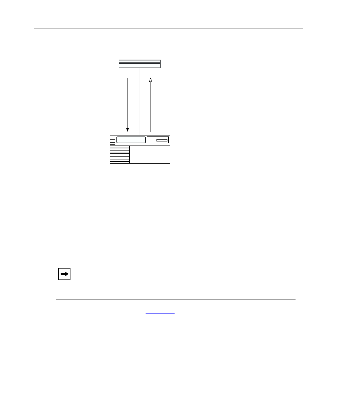
Understanding Tools and Options
AN/ANH/ARN router
BOOTP request
Upstream router
IP address 192.32.1.1
BOOTP response with
IP address 192.32.1.2
NPA0001A
Figure 1-1. Calculating an IP Address
(Direct Access PVC or Standard PPP)
-- A frame relay PVC in group access mode refers to its BootP client
interface table to find an associated IP address for the AN/ANH or ARN
router.
The BootP client interface table contains a data link connection
Note:
identifier (DLCI) and IP address pair for each PVC. You use Site Manager to
create this table when you follow the instructions for setting up routing paths
in Chapter 3.
308614-14.20 Rev 00
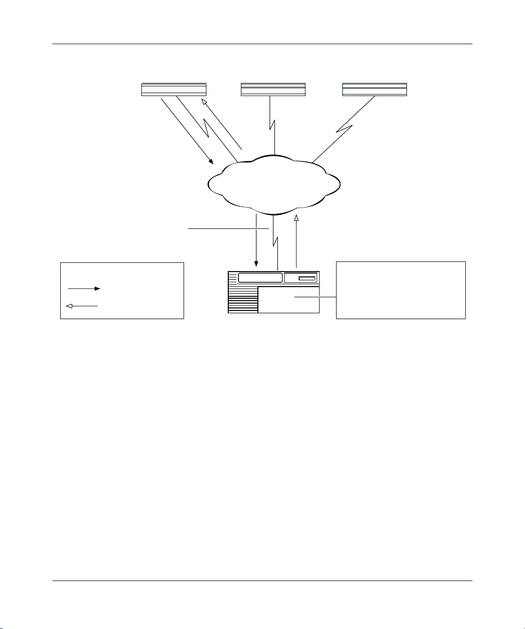
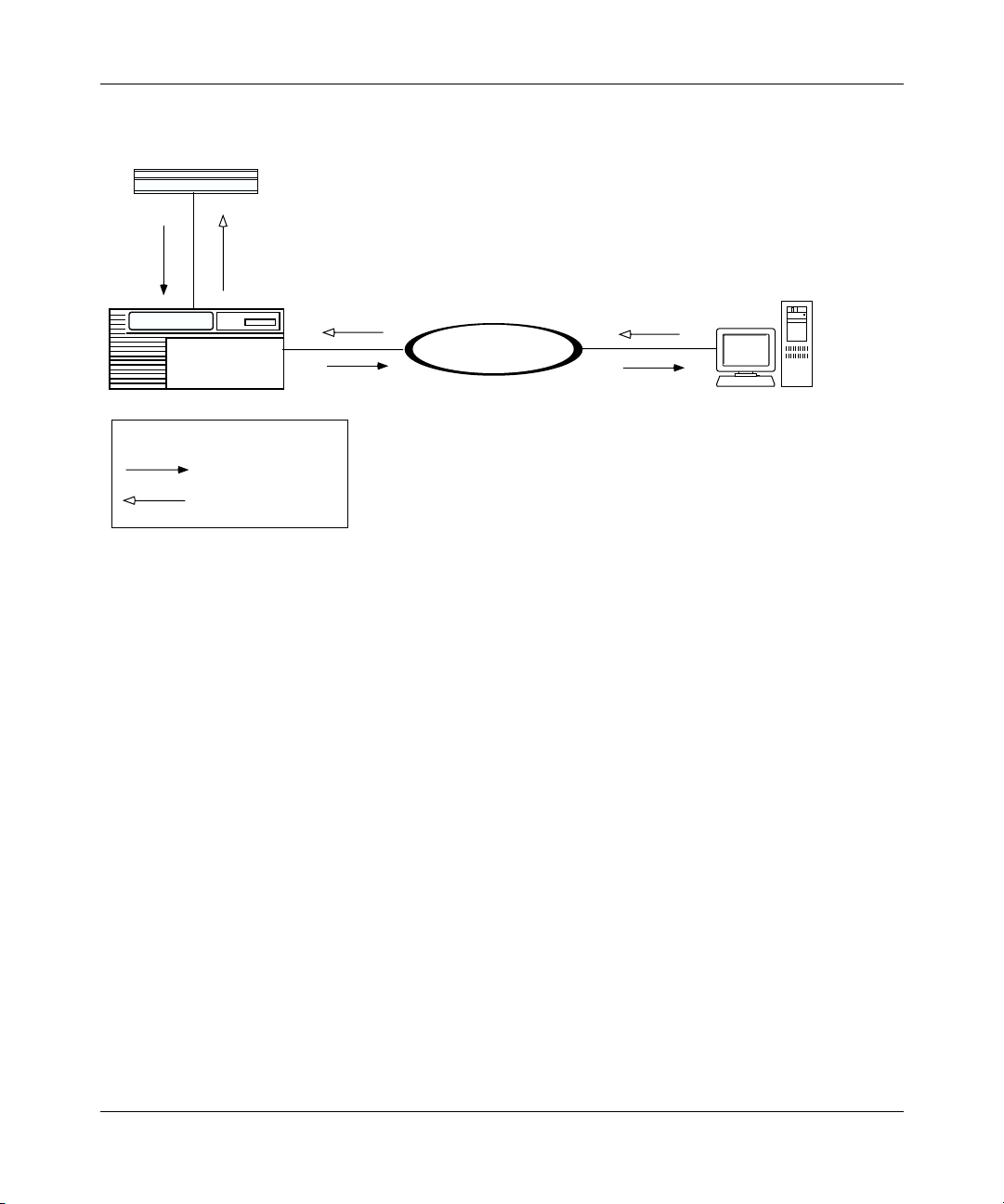
For example, in Figure 1-2
, the AN/ANH or ARN router sends BootP
requests for its IP address. The upstream router receives the request on
PVC 31. The upstream router determines the DLCI, refers to DLCI 31 in
the BootP client interface table, finds the IP address, and sends a BootP
response containing the IP address back to PVC 31.
1-7
Page 26
Configuring Remote Access for AN and Passport ARN Routers
AN/ANH/ARN
Circuit containing PVC 31, 32, 33 (for
virtual connections to the three routers)
Key
BOOTP request
BOOTP response
Booting router 2 Booting router 3
PVC 32
PVC 31
Frame Relay
Upstream router
PVC 33
BOOTP Client Interface Table:
DLCI 31 192.32.1.2
DLCI 32 192.32.1.3
DLCI 33 192.32.1.4
NPA0002A
Figure 1-2. Requesting an IP Address from the BootP Server (Group Access PVC)
The upstream router sends the IP address and subnet mask to the AN/ANH or
5.
ARN router in a BootP response message.
6.
The AN/ANH or ARN router assigns the IP address and subnet mask to any
serial interface that receives a BootP response.
7.
The AN/ANH or ARN router stores these IP addresses, along with the IP
address of the next-hop router, in RAM.
If more than one serial interface receives a BootP response, the AN/ANH or
ARN router assigns an IP address to each interface.
1-8
308614-14.20 Rev 00
Page 27
AN/ANH/ARN
Understanding Tools and Options
Obtaining the Kernel and Configuration Files
With a known IP address, an AN/ANH and ARN router can obtain its
operating-system kernel and configuration files over the network. The procedure
is the same for EZ-Install, Netboot, and Directed Netboot.
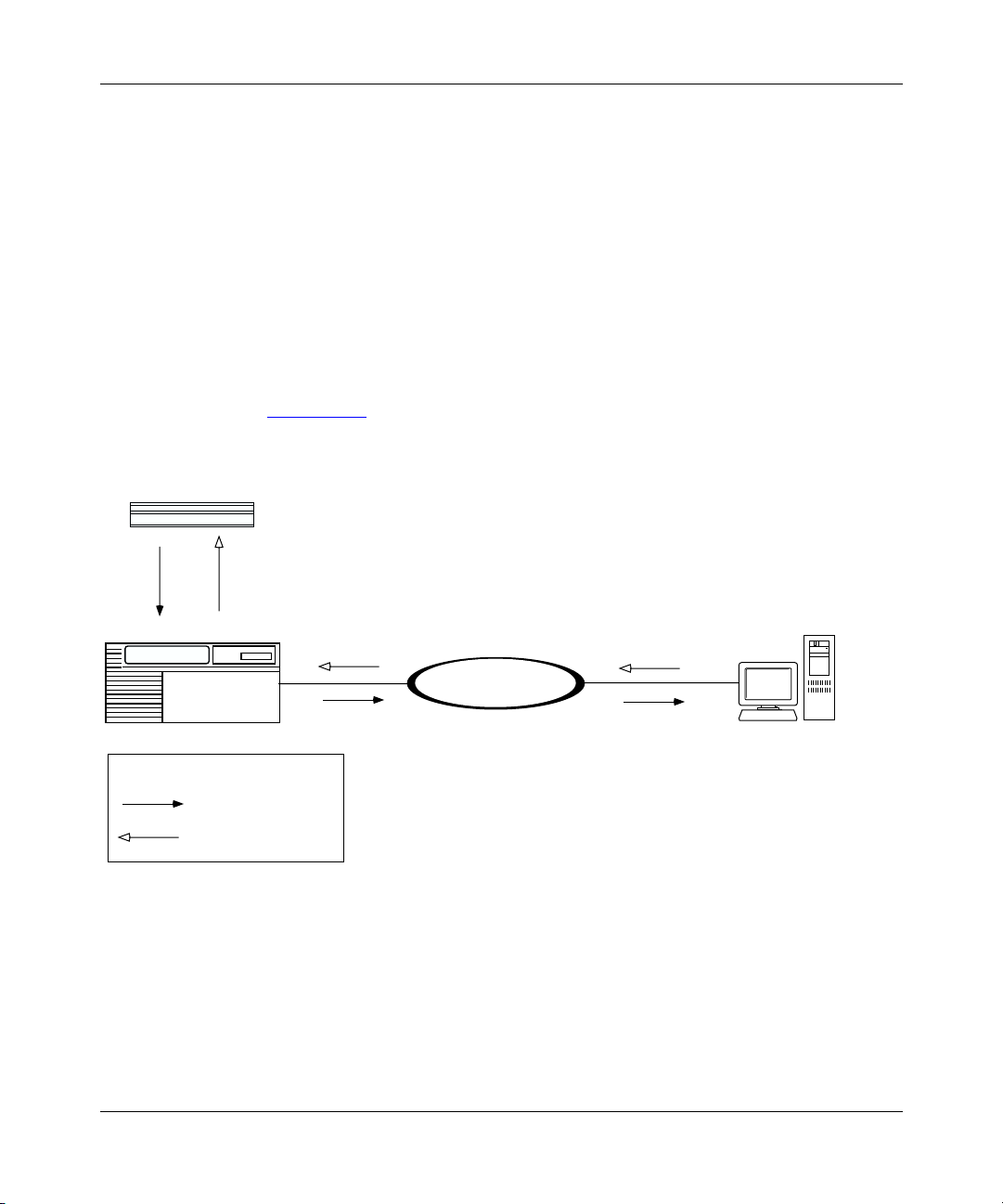
1.
The router sends a BootP request for the path names of the startup files.
The router issues the request simultaneously through all serial (COM),
Ethernet, and token ring (ARN only) interfaces that have IP addresses. The
router issues this request periodically for approximately 3 minutes, regardless
of whether a cable is connected.
2.
A BootP server responds to the router’s request with the directory path names
(Figure 1-3)
.
Upstream router
Pathnames
Corporate backbone
BOOTP
server
Key
BOOTP request
BOOTP response
Figure 1-3. Obtaining the Path Names of the Kernel and Configuration Files
The first router interface that processes the BootP response acts as the TFTP
client in the remaining steps.
3.
The router stops sending BootP requests.
308614-14.20 Rev 00
NPA0003A
1-9
Page 28
Configuring Remote Access for AN and Passport ARN Routers
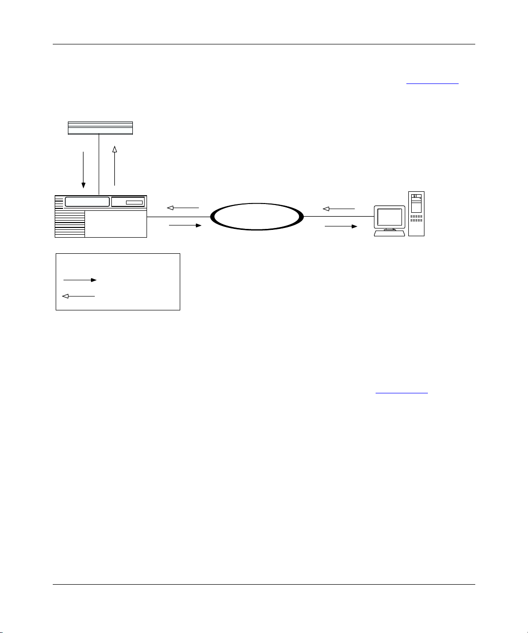
4.
The router sends a TFTP request for the configuration file.
5.
The BootP server uses TFTP to transfer the configuration file (Figure 1-4).
AN/ANH/ARN
Configuration file
Corporate backbone
Upstream router
Key
TFTP request
TFTP transfer
Figure 1-4. Obtaining the Configuration File
6.
The router sends a TFTP request for the kernel file.
7.
The BootP server uses TFTP to transfer the kernel file (Figure 1-5).
BOOTP server
BOOTP response
NPA0004A
1-10
308614-14.20 Rev 00
Page 29
Understanding Tools and Options
AN/ANH/ARN
Kernel
Corporate backbone
Upstream router
Key
TFTP request
TFTP transfer
Figure 1-5. Obtaining the Kernel File
The router boots the kernel.
8.
9.
The router uses TFTP to obtain application and string files as it needs them.
10.
The router begins bridging and routing network traffic as specified in the
configuration file.
The AN/ANH, or ARN router can continue to request files, even after it begins
bridging and routing traffic.
If a failure occurs in steps 1 through 8, the AN/ANH or ARN router attempts to
boot locally.
BOOTP server
NPA0005A
308614-14.20 Rev 00
1-11
Page 30
Configuring Remote Access for AN and Passport ARN Routers
Local Boot Process
When the AN/ANH and ARN routers boot locally, they read the kernel,
application, and string files embedded in the an.exe or arn.exe software image file
on the local PCMCIA flash memory card.
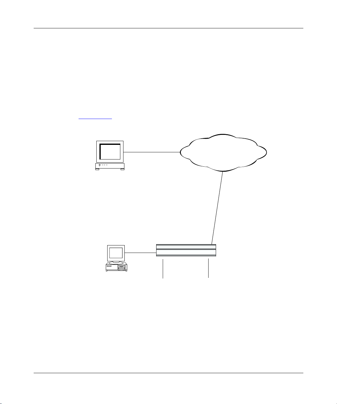
When you use Local Boot as the initial boot option, you boot a default (generic)
configuration file. You must then run the Quick-Start installation script to
customize the default configuration file. Running the installation script establishes
an IP network interface between the router and a Site Manager workstation
(Figure 1-6)
IP address = 192.32.10.12
.
Corporate IP network
Site Manager
workstation
1-12
ASCII console or PC
Console port
AN/ANH/ARN
Ethernet port
IP address = 192.32.156.7
Subnet mask = 255.255.255.0
NPA0006A.EPS
Figure 1-6. Establishing an IP Network Interface
Appendix C briefly describes the procedure for customizing the default
configuration file, provides worksheets for preparing to run the procedure, and
explains how to begin the Quick-Start installation script.
308614-14.20 Rev 00
Page 31

Preparing for the Initial Startup
The first time you turn on an AN/ANH or ARN router, it begins a startup
procedure to obtain the files it needs to operate routinely over the network. For the
procedure to be successful, you must first complete the following tasks:
• Select the initial startup option (see the next section,“Selecting the Initial
Startup Option”)
• Set up the network to support the startup option (see Chapter 3)
• For options other than EZ-Install, configure the router for the startup option
(see Chapter 4)
• Provide a tailored configuration file for the router (see “Providing a Tailored
Configuration File” on page 1-15)
• Coordinate the initial startup with a person at the router site
The person at the router site installs the hardware and cables, and then
initiates the appropriate startup option. The router hardware installation guide
explains these tasks in detail.
Understanding Tools and Options
Note:
As an alternative to another person performing the initial startup at the
AN/ANH or ARN router site, you can perform these tasks using a modem
connection.
Selecting the Initial Startup Option
By default, the EZ-Install procedure begins when you turn on an AN/ANH or
ARN routers router. You can change the initial startup option to Local Boot or
Netboot.
308614-14.20 Rev 00
1-13
Page 32

Configuring Remote Access for AN and Passport ARN Routers
This section reviews the options for initial startup and lists the requirements for
each startup option. “Selecting the Routine Startup Option
similar information for routine operation. “Steps for Completing Startup Options
on page 1-18
Note:
describes the procedure for configuring a startup option.
Even if you use the default option, EZ-Install, Nortel Networks strongly
recommends that you connect a modem or a console to an AN/ANH or ARN
router for initial startup. With a console connection, you can issue commands
to the router and display messages. This is very useful if you have network
problems after installation.
EZ-Install
EZ-Install is the easiest option for the person at the router site to perform, because
AN/ANH and ARN routers automatically begin the procedure at startup, and the
network automatically supplies the IP address and configuration file.
The EZ-Install procedure requires the following at initial startup:
• A communications link between the AN/ANH or ARN router and an
upstream router over an HDLC or frame relay interface
” on page 1-16 provides
”
1-14
• A BootP server that contains a customized configuration file for the AN/ANH
or ARN router
If EZ-Install fails in an initial startup attempt, one of the following occurs:
• An AN or ANH router attempts to boot once using the Local Boot option. If
both boot attempts fail, you must troubleshoot the problem and reboot the
router as described in Appendix B.
• An ARN router first tries to local boot, and then tries to netboot. The ARN
continuously attempts to local boot and netboot until it boots successfully, you
turn off the ARN, or you interrupt the process in one of the following ways:
-- Press the Reset button on the ARN back panel
-- Type the [Control]-c break sequence at the management console
Local Boot
The Local Boot procedure requires the following at initial startup:
• An installed PCMCIA flash memory card that contains the software image
file and a generic configuration file
308614-14.20 Rev 00
Page 33

Understanding Tools and Options
• A local console or modem connection with the AN/ANH or ARN router
When you use Local Boot as the initial boot option, the Site Manager connection
is not yet in place. AN/ANH and ARN routers boot using the generic
configuration file; then, you must run the Quick-Start installation script to
customize the configuration file and save it locally (see Figure 1-6
on page 1-12).
See the description of the Quick-Start installation procedure in Appendix C.
Netboot
The Netboot procedure requires the following at initial startup:
• A communications link between the AN/ANH or ARN router and an
upstream router over an Ethernet, HDLC, frame relay, or token ring (ARN
only) interface
• A local console or modem connection with the AN/ANH or ARN router
• A BootP server that contains the software image file (arn.exe for the ARN or
an.exe for the AN/ANH) or a network configuration file (config) customized
for the AN/ANH or ARN router
• An IP address assigned to the AN/ANH or ARN router’s boot interface
Providing a Tailored Configuration File
Since AN/ANH and ARN routers ship with a generic configuration file on the
PCMCIA flash memory card, you must tailor that file to your network before a
router can bridge and route traffic.
You can provide the AN/ANH and ARN routers with a tailored configuration file
during the initial startup in one of the following ways:
• Place a tailored configuration file on the server for the router to download
during EZ-Install or another netboot procedure.
See “Preparing Configuration and Image Files” in Chapter 3 for information
about creating a tailored configuration file.
• Allow the router to start using the generic configuration file during a Local
Boot procedure; then, use the Technician Interface Quick-Start installation
script to configure one or more interfaces for IP so that the router can connect
to Site Manager (or another network management tool).
308614-14.20 Rev 00
1-15
Page 34

Configuring Remote Access for AN and Passport ARN Routers
The Quick-Start procedure initially tailors the default configuration file; use
Site Manager to complete the configuration. See Appendix C for more
information.
Selecting the Routine Startup Option
This section provides information to help you select the boot configuration for
routine startup operations.
Recommendations
Nortel Networks recommends that you do the following:
• Maintain the complete software image file (an.exe or arn.exe) on the local file
system at all times, in case the network connection to the BootP server goes
down and the router needs to use Local Boot for startup.
• Set up the network to support Netboot even if you plan to use the Local Boot
option. With the network set up to support Netboot, you can boot the router
over the network for some procedures and boot it locally for others.
Netboot
1-16
Netboot takes longer than the other startup options, but has many benefits.
Note:
Over a low-speed WAN, or after configuring AN/ANH and ARN
routers to run several protocols, netbooting can take up to 15 minutes. It takes
less time to netboot only the kernel file or configuration file.
Using Netboot for routine startups allows you to:
• Manage software image and configuration files from a remote location by
storing them on the BootP server
This option greatly simplifies the management of remote routers by allowing
you to keep the startup files up-to-date in a single location -- the BootP server.
308614-14.20 Rev 00
Page 35

Understanding Tools and Options
• Minimize the need to maintain the router’s local file system
When the an AN/ANH or ARN router obtains files from a BootP server, it
stores them in memory, not in its file system, reducing the need for frequent
file-system compactions. (See Using Technician Interface Software or
Configuring and Managing Routers Using Site Manager to learn about
compacting a file system.)
• Restore a corrupted file system
The router’s file system resides on an installed flash memory card. With
Netboot enabled, the AN/ANH or ARN router can still boot over the network
if the local files become corrupted. (When the router reboots due to a reset or
power loss, it automatically boots the configuration and image files over the
network if it cannot find intact files locally.)
• Obtain application and string files from the BootP server as the router needs
them
Obtaining these files individually, rather than obtaining the entire an.exe or
arn.exe file, reduces line costs and the use of flash memory space.
The Netboot procedure requires the following at initial startup:
• A communications link between the AN/ANH or ARN router and an
upstream router over an Ethernet, HDLC, frame relay, or token ring (ARN
only) interface
• A local console or modem connection with the AN/ANH or ARN router
• A BootP server that contains the operating-system kernel (krnl_arn.exe for the
ARN or krnl_an.exe for the AN/ANH) or a network configuration file
customized for the AN/ANH or ARN router
• An IP address assigned to the AN/ANH or ARN router boot interface
Directed Netboot
The Directed Netboot procedure requires the following at initial startup:
• A communications link between the AN/ANH or ARN router and an
upstream router over an Ethernet, HDLC, frame relay, or token ring (ARN
only) interface
• A local console or modem connection with the AN/ANH or ARN router
308614-14.20 Rev 00
1-17
Page 36

Configuring Remote Access for AN and Passport ARN Routers
• A TFTP server that contains the kernel file (krnl_arn.exe for the ARN or
krnl_an.exe for the AN/ANH) or a network configuration file customized for
the AN/ANH or ARN router
Compared with Netboot, Directed Netboot offers the following advantages:
• Creates less network traffic
• Is generally faster
Directed Netboot is usually reserved for starting AN/ANH and ARN routers after
the initial startup because you need to know the exact location of the startup files.
During Directed Netboot, AN/ANH and ARN routers transfer files from a TFTP
server directly, bypassing negotiation with a BootP server for the IP address and
path names of the startup files.
Local Boot
Local-booting the startup files for routine startups allows you to:
• Minimize the time it takes the router to boot
In most configurations, however, the difference between the two options is
only a few seconds. Typically, local-booting takes two to three minutes.
• Minimize line usage
Obtaining files locally prevents an increase in network traffic during the
startup process.
When you choose the Local Boot option for routine startups, AN/ANH and ARN
routers read the IP addresses from the local configuration file and assign them to
the appropriate interfaces.
Steps for Completing Startup Options
This section summarizes the steps for completing these startup options:
• EZ-Install
• Netboot
• Directed Netboot
• Local Boot
1-18
308614-14.20 Rev 00
Page 37

EZ-Install
Understanding Tools and Options
You can use Netboot for some procedures and Local Boot for others, provided you
have set up the network to support Netboot.
To boot an AN/ANH or ARN router over the network, all routers in the
Note:
path to the BootP server must be running BayRS Version 7.60 or later.
Complete the following steps for the EZ-Install option:
1.
Use the Configuration Manager in local mode to create a complete
configuration file for the router. (See Chapter 3 and Configuring and
Managing Routers with Site Manager.)
2.
Set up a UNIX workstation on the network to support BootP. (See Chapter 2.)
3.
Create a BootP client on the upstream router to support automated addressing,
and configure all routers between the BootP server and the AN/ANH or ARN
router as BootP relay agents. (See Chapter 3.)
4.
Ensure that there is a network connection from a synchronous interface on the
AN/ANH or ARN router to the upstream router.
If the AN/ANH or ARN router will connect to the upstream router over
Note:
a frame relay circuit, ensure that the upstream router is running BayRS Version
7.80 or later.
5.
A person at the AN/ANH or ARN router site installs and turns on the router.
(See the model-specific hardware installation guide.)
The AN/ANH or ARN router obtains a software image from its local file
system, an IP address from the upstream router, and the customized
configuration file from the BootP server. (“The Boot Process
” on page 1-5
describes this process; no action is required.)
If the configuration file meets your network requirements, the AN/ANH or
ARN router starts bridging and routing traffic.
6.
Use the Site Manager Statistics Manager and Events Manager tools to verify
that the AN/ANH or ARN router is routing traffic as specified in the
configuration file. (See Configuring and Managing Routers with Site
Manager.)
308614-14.20 Rev 00
1-19
Page 38

Configuring Remote Access for AN and Passport ARN Routers
Netboot
Complete the following steps for the Netboot option:
1.
Use the Configuration Manager in local mode to create a complete
configuration file for the AN/ANH or ARN router. (See Chapter 3 and
Configuring and Managing Routers with Site Manager.)
2.
Set up a UNIX workstation on the network to support BootP. (See Chapter 2.)
3.
Use Site Manager to enable BootP on each router interface between the router
and the BootP server. (See Chapter 3.)
4.
Ensure that there is a network connection from a synchronous, Ethernet, or
token ring (ARN only) interface on the AN/ANH or ARN router to the
upstream router.
If the AN/ANH or ARN router will connect to the upstream router over
Note:
a frame relay circuit, ensure that the upstream router is running BayRS Version
7.71 or later.
5.
Install the kernel and application files in the BootP server’s file system, and
make sure that they reside in the same directory. (See Chapter 2.)
1-20
6.
The person at the AN/ANH or ARN router site establishes a Technician
Interface session, or you establish a session using a modem. (See the hardware
installation guide.)
7.
The person at the AN/ANH or ARN router console uses the
ifconfig
commands to configure a synchronous, Ethernet, or token ring (ARN
bconfig
only) interface. (See Chapter 4 and the hardware installation guide.)
8.
The person at the AN/ANH or ARN router site boots the router. (See the
hardware installation guide.)
After the AN/ANH or ARN router boots, it obtains at least one startup file
from the BootP server. If the configuration file meets your network
requirements, the router starts bridging and routing traffic.
9.
Use the Site Manager Statistics Manager and Events Manager tools to verify
that the AN/ANH or ARN router is routing traffic as specified in the
configuration file. (See Configuring and Managing Routers with Site
Manager.)
308614-14.20 Rev 00
and
Page 39

Directed Netboot
Complete the following steps for the Directed Netboot option:
1.
Use the Configuration Manager in local mode to create a complete
configuration file for the AN/ANH or ARN router. (See Chapter 3 and
Configuring and Managing Routers with Site Manager.)
2.
Set up a network server to support TFTP. (See Chapter 2.)
3.
Install the router image and/or configuration files in the TFTP server’s file
system. (See Chapter 2.)
4.
Ensure that there is a network connection from a synchronous, Ethernet, or
token ring (ARN only) interface on the AN/ANH or ARN router to the
upstream router.
Note:
a frame relay circuit, ensure that the upstream router is running BayRS Version
8.00 or later.
Understanding Tools and Options
If the AN/ANH or ARN router will connect to the upstream router over
5.
The person at the AN/ANH or ARN router site establishes a Technician
Interface session, or you establish a session using a modem. (See the hardware
installation guide.)
6.
The person at the AN/ANH or ARN router console uses the
ifconfig commands to configure a synchronous, Ethernet, or token ring (ARN
bconfig
only) interface. (See Chapter 4 and the hardware installation guide.)
7.
The person at the AN/ANH or ARN router site boots the router. (See the
hardware installation guide.)
The AN/ANH or ARN router obtains one or more startup files from the TFTP
server. If the configuration file meets your network requirements, the router
starts bridging and routing traffic.
8.
Use the Site Manager Statistics Manager and Events Manager tools to verify
that the AN/ANH or ARN router is routing traffic as specified in the
configuration file. (See Configuring and Managing Routers with Site
Manager.)
and
308614-14.20 Rev 00
1-21
Page 40

Configuring Remote Access for AN and Passport ARN Routers
Local Boot
Complete the following steps for the Local Boot option:
1.
Complete the Quick-Start configuration worksheets. (See Appendix C.)
2.
The person at the AN/ANH or ARN router site establishes a Technician
Interface session, or you establish a session using a modem. (See the hardware
installation guide.)
If you are not at the router console, provide the person at the console with the
information in the configuration worksheets. The hardware installation guide
contains duplicate worksheets. (See Appendix C.)
3.
The person at the router console runs the installation script (install.bat for the
AN/ANH and inst_arn.bat for the ARN), using the information provided in
the worksheets you completed in step 1. (See Appendix C and your hardware
installation guide.)
4.
The installation script records the responses in a configuration file.
(See Appendix C and your hardware installation guide.)
If the configuration file meets your network requirements, the router starts
bridging and routing traffic.
1-22
5.
Use the Site Manager Statistics Manager and Events Manager tools to verify
that the AN/ANH or ARN router is routing traffic as specified in the
configuration file. (See Configuring and Managing Routers with Site
Manager.)
308614-14.20 Rev 00
Page 41

Chapter 2
Setting Up a UNIX Boot Server
To support network booting, you need to set up a UNIX workstation on the
network to run BootP and TFTP. This chapter describes what you need to do at a
UNIX workstation to prepare AN/ANH and ARN routers for booting over the
network.
Topic Page
Setting Up a BootP Server
Setting Up a TFTP Server 2-9
What to Do Next 2-13
2-2
When AN/ANH and ARN routers boot over the network, they obtain one or more
of its startup files from a UNIX server. When AN/ANH and ARN routers use
EZ-Install or Netboot, the server supplies startup file path names using BootP. The
routers then retrieve the files using TFTP. When AN/ANH and ARN routers use
Directed Netboot, they already know the path names of the files they need and
retrieve the files directly from the server using TFTP.
Complete the appropriate sections of this chapter for the startup option you are
configuring:
To Configure This Startup Option Complete These Sections
EZ-Install • Setting Up a BootP Server
• Setting Up a TFTP Server
Netboot • Setting Up a BootP Server
• Setting Up a TFTP Server
Directed Netboot • Setting Up a TFTP Server
308614-14.20 Rev 00
2-1
Page 42

Configuring Remote Access for AN and Passport ARN Routers
Setting Up a BootP Server
To support EZ-Install or Netboot, AN/ANH and ARN routers need a network
connection to a BootP server. You configure a UNIX workstation as a BootP
server by:
• Setting up BootP sockets
• Configuring the BootP Daemon (BootPD)
Setting Up BootP Sockets
A socket is a UNIX mechanism for creating virtual connections between
operating-system and network processes. For each socket, the /etc/services file
must include a User Datagram Protocol (UDP) descriptor that provides
process-to-process addressing information.
To set up the send and receive sockets for BootP:
1. Log in to the UNIX workstation as root.
2. Use a text editor to insert the following two lines in the /etc/services file:
bootps 67/udp # bootp server
bootpc 68/udp # bootp client
Configuring BootPD
A daemon is an unattended process (that is, one that runs in the background). An
application typically calls a daemon to perform a standard routine or service (in
this case, BootP).
Complete the following tasks to configure BootPD on a UNIX workstation:
• On Sun workstations, copy the BootPD program to the /etc directory.
• Set up BootPD to run.
• Set up BootPD to respond to AN/ANH and ARN routers.
Copying BootPD on Sun Workstations
Depending on the operating system you use, Nortel Networks may or may not
ship BootPD with the Site Manager package.
2-2
308614-14.20 Rev 00
Page 43

Setting Up a UNIX Boot Server
The AIX and HP-UX operating systems include BootPD. SunOS and Solaris do
not include BootPD, so Site Manager automatically installs BootPD on Sun
workstations running these operating systems.
Copy the bootpd file to the /etc directory as follows:
1. Log in to the UNIX workstation as root.
Enter the following command:
2.
cp /usr/wf/bin/bootpd /etc
Setting Up BootPD to Run
To configure your workstation to run BootPD when it receives a BootP request
packet:
1. As root, use a text editor to open the /etc/inetd.conf file.
2. Make sure that no other line in the file begins with
bootps
.
If there is such a line, your workstation is already configured as a BootP
server. Comment out this line by typing a pound sign (#) at the beginning of
the line so that the server will use the BootPD program that you specify in the
next step.
3. Insert the following line anywhere in the file to configure your
workstation as a BootP server:
bootps dgram udp wait root /etc/bootpd bootpd
4. Save and exit the file.
Setting Up BootPD to Respond to AN/ANH and ARN Routers
When the operating system receives a BootP request packet, it starts BootPD.
BootPD matches the source IP address of the packet to an IP address in its BootP
table (bootptab file) to determine the path names of the requested startup files.
The bootptab file can include the same path name for all booting
Note:
routers, or a different path name for each IP address.
308614-14.20 Rev 00
2-3
Page 44

Configuring Remote Access for AN and Passport ARN Routers
Entries in bootptab also include optional parameter tags. Nortel Networks
supplies a sample bootptab file that Site Manager installs automatically in the /
usr/wf/config directory. Use a copy of this sample file if you do not already have a
bootptab file.
To set up BootPD to respond to booting routers:
1. As root, view the contents of the /etc directory to determine if it already
contains a bootptab file.
If it does contain a bootptab file, skip steps 2 and 3 and proceed to step 4 to
edit this file.
2. Enter the following command to copy the bootptab file to the /etc
directory:
cp /usr/wf/config/bootptab /etc
3.
Use a text editor to open the bootptab file in the /etc directory.
4. In the bootptab file, type the information that pertains to the AN/ANH
and ARN routers in your network.
The section that follows explains how to format your entries. Use Tables 2-1
and 2-2
to determine which tags and values you need. Figure 2-1 shows the
sample bootptab file included with the Site Manager software. The comments
in this file explain the sample definitions.
5. Save the bootptab file changes.
The bootptab file must reside in the /etc directory. BootPD fails if it
Note:
cannot find the bootptab file in /etc.
Editing the bootptab File
Specify a hostname definition in the bootptab file for each AN/ANH or ARN
router in your network. The format of each definition in the bootptab file is as
follows:
<
hostname
:
<tg>=<value>
:
<tg>=<value>
:
<tg>=<value>
>:\
:\
:\
:
2-4
308614-14.20 Rev 00
Page 45

Setting Up a UNIX Boot Server
hostname
•
router is a client). Each
is a name you assign to a BootP client (each AN/ANH or ARN
hostname
definition must:
-- Contain a maximum of 79 characters
-- Contain alphanumeric characters, and an alphabetic first character
-- Not contain an underscore (_)
• You can use a dot (.) to separate characters, but the character immediately
following the dot must be alphabetic.
tg
is a BootP parameter name (tag).
•
• Follow each tag with an equals sign (=) and a value.
• A pound sign (#) at the beginning of a line indicates a comment.
• A backslash (\) at the end of a line indicates continuation of the line.
Note:
Make sure you type a backslash (\), not a slash (/), at the end of each
line that does not conclude a definition.
Tabl e 2- 1
tags for kernel file names.
Table 2-1. BootPD Tags for a Router Host Name
Tag
ip Required IP address -- the host IP address
sm Optional Subnet mask -- the host subnet
T129 Required Path name of the router
T130 Required Size of the router configuration file
308614-14.20 Rev 00
lists the BootPD tags for router host names. Tab le 2 -2 lists the BootPD
Required or
Optional Value Example
ip=192.32.5.2
of the router
sm=255.255.255.0
mask of the router
T129="/usr/cfg/
configuration file. The maximum
length is 49 characters.
in 512-byte blocks. This tag
determines how much memory the
router allocates for the file. Set this
tag to 0x0004.
an_Bost.cfg"
T130=0x0004
(continued)
2-5
Page 46

Configuring Remote Access for AN and Passport ARN Routers
Table 2-1. BootPD Tags for a Router Host Name
Required or
Tag
tc Optional Table continuation -- a pointer to
Optional Value Example
another location in the same file
for additional information. This tag
points to information that is
common to all routers that use
BootPD. If the information
contradicts information in a
specific host-name definition,
BootPD uses the information in
that definition.
Table 2-2. BootPD Tags for a Kernel File Name
Required
Tag
hd Required Home directory -- the directory on
or Optional Value Example
the workstation containing the
kernel files. By default, the Image
Builder writes its files to the
directory specified in the example.
(continued)
tc=general
hd=/$HOME/.builder_dir/
rel120/an
2-6
rel<number>
The
contains the current BayRS
release. If you change the default
or move the files to another
directory, specify that directory.
bf Required Boot file -- the name of the kernel
file.
bs Required Boot size
file in 512-byte blocks. If you
specify auto as the size, the BootP
server calculates the size of the
file for each BootP request.
directory
-- the size of the kernel
bf=krnl_an.exe
bs=auto
(continued)
308614-14.20 Rev 00
Page 47

Setting Up a UNIX Boot Server
Table 2-2. BootPD Tags for a Kernel File Name
Required
Tag
vm Required Vendor magic cookie selector
or Optional Value Example
the BootP server should always
reply in a manner compliant with
RFC 1048. You must specify
rfc1048 for this tag in order for the
router to understand the BootP
responses it receives.
(continued)
--
vm=rfc1048
The sample bootptab file shown in Figure 2-1 enables two ANs (named
AN.Boston and AN.Chicago) to boot over the network. Use the basic format
shown in Figure 2-1
to set up your own bootptab file.
Verifying Consistent BootP Service
You may want to configure a second workstation as a BootP server for backup
purposes. If you do so, make sure that the two bootptab files are identical. Also,
make sure that the kernel, application, and string files are from the same BayRS
version.
# This file contains the default specification for the boot
# image file to be used by all ANs.
# "general" contains information that is common to all ANs
# that need to boot via BOOTP. You can use any word in place
# of "general."
# "hd" specifies that /$HOME/.builder_dir/rel900/an is the
# directory on the workstation where the boot files are
# located. By default, the Image Builder writes its files to
# this directory. If you are using a router software version
# later than 8.00, add the associated three digits to the end
# of the "rel" directory name. If you moved the files to
# another directory, specify that directory.
# "bf" specifies that the name of the boot image kernel file
# is krnl_an.exe.
Figure 2-1. Sample bootptab File
308614-14.20 Rev 00
general:\
:hd=/$HOME/.builder_dir/rel812/an:\
:bf=krnl_an.exe:\
(continued)
2-7
Page 48

Configuring Remote Access for AN and Passport ARN Routers
# "bs" indicates the size of the boot file. If you specify
# "auto" as the size, the BOOTP server calculates the size of
# the file for each BOOTP request.
:bs=auto:\
# "vm" indicates that the BOOTP server should always reply in
# a manner compliant with RFC 1048. You must enter rfc1048
# for this tag so that the AN can understand the BOOTP
# responses it receives.
:vm=rfc1048:
# This line marks the beginning of the active definition for
# the AN we are naming "AN.Boston."
AN.Boston:\
# "ip" indicates the IP address of the AN.
:ip=192.32.5.2:\
# "T130" indicates the size of the AN’s configuration file in
# 512-byte blocks. Always use 0x0004.
:T130=0x0004:\
# "T129" indicates the pathname of the configuration file
# for the AN.
:T129="/usr1/cfg/AN_Bost.cfg":\
2-8
# "tc" indicates that the "general" definition contains more
# information that applies to BOOTP transmissions to
# "AN.Boston."
:tc=general:
# This is the active definition for the AN we are naming
# "AN.Chicago."
AN.Chicago:\
:ip=10.0.0.4:\
:T130=0x0004:\
:T129="/rte3/cfg/AN_Chic.cfg":\
:tc=general:
Figure 2-1. Sample bootptab File
(continued)
308614-14.20 Rev 00
Page 49

Setting Up a TFTP Server
AN/ANH and ARN routers need a network connection to a TFTP server to
complete EZ-Install, Netboot, or Directed Netboot. You configure a UNIX
workstation as a TFTP server by:
• Setting up the TFTP daemon (TFTPD) to provide TFTP access
• Setting up static routes to AN/ANH and ARN routers (optional)
• Loading the changes into memory
Setting Up TFTPD
When you set up the TFTPD server on a UNIX workstation, you can allow TFTP
access to the root directory and any subdirectory, or restrict TFTP access to a
specified directory or path name.
Allowing TFTP access to all directories is the simpler procedure. Specifying a
directory provides security, but requires either keeping the startup files in the
specified directory or creating a link to each path name.
Setting Up a UNIX Boot Server
Providing TFTP Access to All Directories
To provide TFTP access to files in the root (/) directory and all subdirectories,
insert the appropriate line for your operating system in the /etc/inetd.conf file.
Find the sample line for your operating system in Tabl e 2- 3
Table 2-3. Providing TFTP Access to All Directories
Operating
System Sample Line to Insert in /etc/inetd.conf File, or Other Instruction
SunOS tftp dgram udp wait root /usr/etc/in.tftpd in.tftpd -s /
Solaris tftp dgram udp wait root /usr/sbin/in.tftpd in.tftpd -s /
HP-UX tftp dgram udp wait root /etc/tftp tftp
AIX Use the System Management Interface Tool (SMIT) to configure TFTP. For
308614-14.20 Rev 00
.
instructions, see the IBM guides on TCP/IP daemons and TFTP.
2-9
Page 50

Configuring Remote Access for AN and Passport ARN Routers
Restricting TFTP Access to Specified Directories
To restrict TFTP access to a specific directory:
1. Log in to your UNIX workstation as root.
Insert the appropriate line in the /etc/inetd.conf file.
2.
The examples in Tab le 2 -4
restrict access to the /tftpboot directory. You can
substitute any directory you want.
Table 2-4. Restricting TFTP Access to Specified Directories
Operating
System Sample Line to Insert in /etc/inetd.conf File, or Other Instruction
SunOS tftp dgram udp wait root /usr/etc/in.tftpd in.tftpd -s
/tftpboot
Solaris tftp dgram udp wait root /usr/sbin/in.tftpd in.tftpd
-s /tftpboot
HP-UX tftp dgram udp wait root /etc/tftp tftp -s /tftpboot
AIX Use the System Management Interface Tool (SMIT) to configure TFTP.
For instructions, see the IBM guides on TCP/IP daemons and TFTP.
3. Create a symbolic link in the specified directory for every startup file
path name.
For example, to set up symbolic links in the /tftpboot directory:
a. Enter the following command to move to the /tftpboot directory:
cd tftpboot
2-10
Note:
Do not insert a slash (/) in the
cd tftpboot
command. A symbolic link
cannot contain references to directories above the directory specified in the
tftpd
command line.
b.
Enter the following commands to create symbolic links:
ln -s . usr
ln -s . tftpboot
308614-14.20 Rev 00
Page 51

Setting Up a UNIX Boot Server
Adding a TFTP User for an HP 9000 Workstation
Follow the instructions in this section only if you are running Site Manager on an
HP 9000 workstation.
To add a TFTP user for the HP 9000, insert the following line in your /etc/passwd
file. Nortel Networks recommends that you use root (/) as the TFTP home
directory.
tftp::
<user_id>:<group_no.>
::/:/bin/false
For example:
tftp::510:20::/:/bin/false
Note:
Nortel Networks recommends that you not use the System
Administration Manager (SAM) utility to add a TFTP user.
Setting Up Static Routes to Next-Hop Routers
If your workstation requires static routes, read this section to learn how to specify
a path to the network by:
• Editing the /etc/inetd.conf file
• Verifying the routes
• Loading the changes into memory
You must set up a static route for each path between the AN/ANH or ARN router
and the BootP server’s next-hop router.
Note:
You may want to specify a static route in a multihop environment or in
an environment using routing protocols such as RIP, where minor routing
update delays may extend the time it takes to Netboot.
Editing the /etc/inetd.conf File
Insert the following line in the /etc/inetd.conf file to set up a static route:
route add
destination
308614-14.20 Rev 00
<destination> <gateway> <hops>
is the IP address of the router or its network.
2-11
Page 52

Configuring Remote Access for AN and Passport ARN Routers
gateway
is the IP address of the network destination to which packets will be
addressed.
hops
is the number of hops to the network destination.
Verifying the Routes
After adding a static route for each path to an AN/ANH or ARN router, enter the
following command to display the routing table and verify the routes you added:
netstat -r
Loading the Changes into Memory
Once you modify the /etc/inetd.conf file, you must force the operating system to
reread it by rebooting the workstation or by issuing a hang-up signal.
In most cases, reboot the workstation. Issue a hang-up signal if the workstation is
performing a task that you do not want to interrupt.
Rebooting Your Workstation
To reboot your workstation:
1. Log in as root.
2-12
-r
2. Enter the following command (the
/etc/shutdown now -r
flag reboots the workstation):
Issuing a Hang-Up Signal
To issue a hang-up signal:
1. Log in as root.
2. Enter the following command to hang up on the inetd process:
ps -aux | grep inetd
The system displays a line similar to this one:
root 148 0.0 0.0 48 0 ? IW Sept 14 0:07 inetd
308614-14.20 Rev 00
Page 53

3.
Enter the following command, using the first number in the line after the
word
kill -1 148
The inetd process rereads the /etc/inetd.conf file.
What to Do Next
Before you can netboot the AN/ANH or ARN router, complete the steps in
Chapter 3.
root
(in this case,
148
Setting Up a UNIX Boot Server
):
308614-14.20 Rev 00
2-13
Page 54

Page 55

Chapter 3
Configuring Netboot Services with Site Manager
This chapter describes how to use Site Manager to configure netboot services for
AN/ANH and ARN routers in the network.
Topic Page
Preparing Configuration and Image Files
Enabling Netboot or Directed Netboot 3-6
Adding a Netboot or Directed Netboot Interface 3-8
Configuring a Netboot or Directed Netboot Interface 3-9
Setting Up Routing Paths for Netboot 3-10
Creating the BootP Client Interface Table 3-14
3-2
Complete the appropriate sections of this chapter for the startup option you are
configuring:
To Configure This Startup
Option Complete These Sections
EZ-Install (default) • Preparing Configuration and Image Files
EZ-Install over Frame Relay
PVC in group-access mode
Netboot • Enabling Netboot or Directed Netboot
Directed Netboot • Enabling Netboot or Directed Netboot
• Preparing Configuration and Image Files
• Creating the BootP Client Interface Table
• Adding a Netboot or Directed Netboot Interface
• Configuring a Netboot or Directed Netboot Interface
• Setting Up Routing Paths for Netboot
• Adding a Netboot or Directed Netboot Interface
• Configuring a Netboot or Directed Netboot Interface
308614-14.20 Rev 00
3-1
Page 56

Configuring Remote Access for AN and Passport ARN Routers
Preparing Configuration and Image Files
AN/ANH and ARN routers ship with a flash memory card that contains a default
(generic) configuration file and the an.exe or arn.exe router software image. For
the AN/ANH and ARN routers in your network, you must create:
• A unique configuration file for each netbooting router
• A uniform software image for all netbooting routers
Creating Configuration Files
To prepare network configuration files:
1. Use the Configuration Manager in local mode to create a configuration
file for each router.
For instructions, see Configuring and Managing Routers with Site Manager.
Also, see the following:
• Tabl e 3- 1
configuration file for AN routers
• Tabl es 3-2
configuration file for ARN routers.
Note:
For ARN routers, you choose base, expansion, and adapter modules
separately.
Site Manager identifies AN and ANH routers with module names that use
mnemonic abbreviations for each of the router’s connectors. For example, the
module name E/T/2S identifies an AN with one Ethernet, one token ring, and two
serial interfaces. The module name 8ptEHub/3S/N11 DCM identifies an 8-port
ANH with a third serial interface and an RMON data collection module (DCM)
installed.
for the Site Manager module name to use when creating a
through 3-4 for the module names to use when creating a
3-2
308614-14.20 Rev 00
Page 57

Configuring Netboot Services with Site Manager
Tabl e 3- 1 lists the mnemonics used in AN and ANH module names.
Table 3-1. Configuration Manager Module Names for AN and ANH
Module Name Mnemonic Connector Type
E Ethernet
T Token ring
2S Two serial
3S Three serial
BRI-S ISDN BRI with S/T interface
BRI-U ISDN BRI with U interface
BRI-S+ ISDN BRI S/T interface, floating B-channel
BRI-U ISDN BRI U interface, floating B-channel
N11 DCM RMON data collection module
CSU_DSU 56/64K DSU/CSU
FT1 T1/Fractional T1
FE1 E1/Fractional E1
8pt EHub 8-port Ethernet hub
12pt EHub 12-port Ethernet hub
For ARN routers, you choose base, expansion, and adapter modules separately.
Tabl e 3- 2
can have only one base module.
Table 3-2. ARN Base Module Configurations
Base Module Site Manager Module Name
Ethernet Ethernet
Ethernet with DCM Ethernet/DCM
Token Ring Token Ring
100 Base-T Ethernet 10/100BASE-TX Ethernet
100 Base-FX Ethernet
(fiber)
308614-14.20 Rev 00
lists the base module (system board) options for ARN routers. An ARN
100BASE-FX Ethernet
3-3
Page 58

Configuring Remote Access for AN and Passport ARN Routers
Tabl e 3- 3 lists the optional expansion modules available for an ARN. An
expansion module is a parallel daughterboard installed on the base module. The
ARN base module supports only one expansion module.
Table 3-3. ARN Expansion Module Configurations
Expansion Module Site Manager Module Name
Ethernet Ethernet
Ethernet with DCM Ethernet/DCM
Token Ring Token Ring
Tri-Serial TRI Serial
Ethernet/Tri-Serial Ethernet/TRI Serial
Ethernet/Tri-Serial with DCM Ethernet/TRI Serial/DCM
Token Ring/Tri-Serial Token Ring/TRI Serial
Tabl e 3- 4
lists the optional adapter modules for an ARN. An adapter module is a
serial daughterboard installed in the front-panel card cage. The ARN base module
supports one or two adapter modules.
Table 3-4. ARN Adapter Module Configurations
Adapter Module Site Manager Module Name
Serial Serial
ISDN BRI S/T ISDN ‘S/T’
ISDN BRI U ISDN ‘U’
56/64K DSU/CSU*
V.34 Modem V34 Modem
X.25 PAD X25 PAD
FT1/T1 DSU/CSU Fractional T1
FE1/E1 G703 Fractional E1
* The ARN supports network booting over DSU/CSU interfaces only for the default
configuration, 56 Kb/s DDS lines. You cannot netboot over a 64 Kb/s DSU/CSU
interface.
56/64K DSU/CSU
3-4
308614-14.20 Rev 00
Page 59

Configuring Netboot Services with Site Manager
2.
Record the name of each configuration file and corresponding router for
later reference when configuring network boot options.
When you name configuration files, keep the following restrictions in mind:
• Nortel Networks recommends that the operational configuration file for
each router be named config. If a router experiences a power failure, it
boots from the file named config when power returns. However, the
configuration files that you save on a BootP server for Directed Netboot
do not have to be named config because you specify the configuration file
path name (see the description of the Site Manager parameter Boot
Config Pathname on page A-3.)
• Configuration file names must begin with an alphabetic character. The
remaining characters must be alphanumeric and can include an
underscore (_). You cannot use spaces.
• Configuration file names can consist of 1 to 15 characters, including a
dot (.). Nortel Networks recommends that you limit file names to 8
characters to ensure that all supported operating systems can recognize
the names.
• Configuration file-name extensions are optional and must follow a file
name and a dot. Nortel Networks recommends that you limit file-name
extensions to three characters.
• BootP allows a maximum of 49 characters in a path name, including
slashes, file name, optional dot, and file-name extension.
3. If the BootP server and Site Manager do not reside on the same
workstation, transfer the configuration files to the BootP server.
Preparing an Image
If you want the router to automatically boot a network-based image when starting
up (using Netboot or Directed Netboot), use the Site Manager Image Builder tool.
To create the kernel, application, and string files for storage on the BootP/TFTP
server:
1. On the Site Manager workstation, open the software image file using the
Image Builder tool.
For instructions on how to use the Image Builder, see Configuring and
Managing Routers with Site Manager.
308614-14.20 Rev 00
3-5
Page 60

Configuring Remote Access for AN and Passport ARN Routers
After you open the image file, the Image Builder automatically extracts the
kernel image file, application files, and string files.
Keep the following in mind:
• Be sure to choose the correct image (an.exe for an AN/ANH, or arn.exe
for an ARN). If you choose an image for another router type, you cannot
generate the correct files.
• The kernel file and all of the application (.exe) files and string (.str) files
must be from the same software image file. If these files are from different
software versions, the router may fail to boot or may not operate properly.
2. If you use a different workstation as a BootP server, transfer to that
workstation all of the files in the directory that contains the kernel file.
The router cannot netboot until the kernel file is available on the BootP server.
Enabling Netboot or Directed Netboot
By default, the router obtains the software image files from its local file system
and its configuration file from a BootP server. You can use Site Manager to
display and change these settings as follows:
3-6
Site Manager Procedure
You do this System responds
1. In the Configuration Manager window,
choose Protocols.
2. Choose Global Protocols. The Global Protocols menu opens.
3. Choose Net Boot. The Net Boot menu opens.
4. Choose Global. The Edit Netboot Global Parameters
The Protocols menu opens.
window opens.
(continued)
308614-14.20 Rev 00
Page 61

Configuring Netboot Services with Site Manager
Site Manager Procedure
You do this System responds
5. Set the following parameters:
• Boot Image From Network
• Boot Config From Network
• Boot Server Address
• Boot Image Pathname*
• Boot Config Pathname
Click on Help or refer to the parameter
descriptions beginning on page A-2.
6. Click on OK. You return to the Configuration Manager
* When you netboot a router, the value of Boot Image Pathname is the full path name of the active
image on the remote server. When you boot a router locally, the name of the active image
(wfHwEntry.wfHwActiveImageName) appears in the form <
Note:
Instead of enabling the Boot Image From Network parameter, you can
(continued)
Site Manager enables Netboot if you
enable one or both of the first two
parameters.
Site Manager enables Directed Netboot if
you enable one or both of the first two
parameters, and then specify values for
the remaining parameters.
window.
volume
>:<
image name
>.
use the Router Files Manager tool to transfer an upgraded image file to the
router. To do this, delete the old image file, compact the file system, and copy
the upgraded image file to the router. To verify that the file transfer was
successful, use the Router Files Manager to confirm that the new image file on
the router is the same size as that on the Site Manager workstation. For more
information about the Router Files Manager, see Configuring and Managing
Routers with Site Manager.
You can also use Technician Interface commands to configure network booting, as
described in Chapter 4.
Note:
UNIX BootP server on the network, as described in Chapter 2.
308614-14.20 Rev 00
Before the router can obtain files over the network, you must set up a
3-7
Page 62

Configuring Remote Access for AN and Passport ARN Routers
Adding a Netboot or Directed Netboot Interface
When you enable Netboot or Directed Netboot, you must add (and configure) at
least one AN/ANH or ARN router circuit as a Netboot interface. If you are using
EZ-Install, you do not need to configure Netboot interfaces. You can use Site
Manager to add a Netboot interface.
Site Manager Procedure
You do this System responds
1. In the Configuration Manager window,
choose Protocols.
2. Choose Global Protocols. The Global Protocols menu opens.
3. Choose Net Boot. The Net Boot menu opens.
4. Choose Interfaces. The Netboot Interfaces window opens.
5. Click on Add. The Netboot Interface window opens.
6. Set the Connector parameter.
Click on Help or refer to the parameter
description on page A-4.
7. Click on OK. You return to the Netboot Interfaces
The Protocols menu opens.
window, which shows the interface you
just added.
3-8
308614-14.20 Rev 00
Page 63

Configuring Netboot Services with Site Manager
Configuring a Netboot or Directed Netboot Interface
You can use Site Manager to configure a Netboot or Directed Netboot interface.
Site Manager Procedure
You do this System responds
1. In the Configuration Manager window,
choose Protocols.
2. Choose Global Protocols. The Global Protocols menu opens.
3. Choose Net Boot. The Net Boot menu opens.
4. Choose Interfaces. The Netboot Interfaces window opens.
5. In the scroll box, choose the interface you
want to configure.
6. Set the following parameters:
• Connector IP Address
• Connector Subnet Mask
• Connector Next Hop
• Connector Protocol Mask
• Connector State
Click on Help or refer to the parameter
descriptions beginning on page A-4.
7. Click on Apply, then click on Done. You return to the Configuration Manager
Note:
If you configure more than one interface to Netboot, the first interface to
The Protocols menu opens.
The window shows the parameter values
for that interface.
window.
receive a reply from the BootP server will complete the Netboot process.
308614-14.20 Rev 00
3-9
Page 64

Configuring Remote Access for AN and Passport ARN Routers
Setting Up Routing Paths for Netboot
You set up the routing paths between the BootP server and the AN/ANH or ARN
router by:
• Enabling each router interface in the paths to the routers
• Creating a BootP relay agent forwarding table for each router in a path
• Creating a BootP client interface table for the upstream router when the router
is on a Frame Relay PVC in group access mode
Enabling Router Interfaces
You must enable BootP relay (also called BootP pass-through or gateway) on all
interfaces in the paths between AN/ANH or ARN routers and the BootP server.
For example, you would enable BootP relay on the interfaces indicated in
Figure 3-1
.
3-10
308614-14.20 Rev 00
Page 65

Configuring Netboot Services with Site Manager
Booting routers
Enable BOOTP on
these interfaces
BOOTP server
Figure 3-1. Enabling BootP Relay in a Sample Network
308614-14.20 Rev 00
Corporate backbone
NPA0007A
3-11
Page 66

Configuring Remote Access for AN and Passport ARN Routers
You can use Site Manager to enable BootP relay on an interface.
Site Manager Procedure
You do this System responds
1. In the Configuration Manager window,
click on the connector on which you want
to enable BootP relay.
2. Choose Edit Circuit. The Circuit Definition window opens.
3. Choose Protocols. The Protocols menu opens.
4. Choose Add. The Select Protocols window opens.
5. Choose BOOTP. The BOOTP menu opens.
6. Choose File. The File menu opens.
7. Choose Exit. You return to the Configuration Manager
The Edit Connector window opens.
window.
Creating BootP Relay Agent Forwarding Tables
You must create a BootP relay agent forwarding table for every router that passes
BootP traffic between the AN/ANH or ARN router and the BootP server.
The BootP relay agent forwarding table allows you to specify the IP interface that
receives the incoming BootP request packets, and the associated IP interface that
forwards them. You can add multiple pairs of incoming and outgoing interfaces to
support connections to multiple routers in your network.
3-12
308614-14.20 Rev 00
Page 67

Configuring Netboot Services with Site Manager
You can use Site Manager to create the BootP relay agent forwarding table.
Site Manager Procedure
You do this System responds
1. In the Configuration Manager window,
The Protocols menu opens.
choose Protocols.
2. Choose IP. The IP menu opens.
3. Choose BOOTP. The BOOTP menu opens.
4. Choose Relay Agent Interface Table. The BOOTP Relay Agent Interface Table
window opens.*
5. Click on Forward I/F (interface). The BOOTP Relay Agent Forwarding
Table window opens.
6. Click on Add. The BOOTP Addresses window opens.
7. Set the following parameters:
• Input IP Address
• Output IP Address
Click on Help or refer to the parameter
descriptions beginning on page A-7.
8. Click on OK. The BOOTP Relay Agent Forwarding
Table window lists the connector and
input IP address on the left, and the
connector and output IP address on the
right.
If you specify an IP address of an
interface that is not configured, ???
appears instead of the connector (for
example, ??? 192.32.23.3). If you
configure the IP address, Site Manager
displays the appropriate connector.
9. Click on Done. You return to the BOOTP Relay Agent
Interface Table window.
* Click on Help or see
parameters in the BOOTP Relay Agent Interface Table window. Make sure that the Timeout Secs.
parameter is set to the default, 0.
Configuring SNMP, BootP, and DHCP Services
for a description of the
308614-14.20 Rev 00
3-13
Page 68

Configuring Remote Access for AN and Passport ARN Routers
Creating the BootP Client Interface Table
The upstream router is the booting router’s next-hop router. By default, the
booting router’s synchronous interfaces automatically try to obtain IP addresses
from the upstream router. This is the EZ-Install process.
If the AN/ANH or ARN router using EZ-Install obtains its address from the
upstream router, and the upstream router’s interface to the AN/ANH or ARN
router is a Frame Relay PVC in group access mode, you must use Site Manager to
connect to the upstream router and create a BootP client interface table (in
addition to a BootP relay agent forwarding table).
Note:
You do not need to create a BootP client interface table if the Frame
Relay PVC is configured to operate in direct access mode, or if the circuit is
configured to operate with Nortel Networks Standard PPP (HDLC
encapsulation).
The BootP client interface table allows you to specify and pair the IP address of
the AN/ANH or ARN router with the DLCI of the Frame Relay group access
PVC.
3-14
Note:
If you are using EZ-Install over Frame Relay, you can have up to 20
PVCs for a single Frame Relay interface on the upstream router. If you have
more than 20 PVCs on the Frame Relay interface, the EZ-Install process may
fail. To ensure that the process does not fail, configure a maximum of 20 PVCs
for a Frame Relay interface.
For more information about the DLCI and Frame Relay, see Configuring Frame
Relay Services.
308614-14.20 Rev 00
Page 69

Configuring Netboot Services with Site Manager
You can use Site Manager to create the BootP client interface table.
Site Manager Procedure
You do this System responds
1. In the Configuration Manager window,
The Protocols menu opens.
choose Protocols.
2. Choose IP. The IP menu opens.
3. Choose BOOTP. The BOOTP menu opens.
4. Choose Relay Agent Interface Table. The BOOTP Relay Agent Interface Table
window opens.*
5. Click on Client I/F (interface). The BOOTP Client Interface Table
window opens.
6. Click on Add. The BOOTP Client Interface Address
window opens.
7. Set the following parameters:
• IP Address
• DLCI Number
Click on Help or refer to the parameter
descriptions beginning on page A-8.
8. Click on OK. The BOOTP Client Interface Table
window lists the client IP interface and the
DLCI number you added.
9. Click on Done. You return to the BOOTP Relay Agent
Interface Table window.
* Click on Help or see
parameters in the BOOTP Relay Agent Interface Table window. Make sure that the Timeout Secs.
parameter is set to the default, 0.
Configuring SNMP, BootP, and DHCP Services
for a description of the
308614-14.20 Rev 00
3-15
Page 70

Page 71

Chapter 4
Configuring Netboot Client Services
This chapter describes how to enable AN/ANH or ARN routers for netboot startup
options using commands at the Technician Interface or AN Monitor prompt.
Topic Page
Using Netboot Configuration Commands
Setting the Boot Configuration 4-3
Setting the Netboot Interface Configuration 4-5
Verifying Your Configuration 4-10
What to Do Next 4-11
First, read “Using Netboot Configuration Commands
” on page 4-2 for
4-2
information about working with someone at a remote AN/ANH or ARN router
site or accessing a router command line. Then, complete the appropriate sections
of this chapter for the AN/ANH or ARN router’s startup configuration:
For This Startup Configuration Complete These Sections
Netboot or Directed Netboot over a
serial interface
Netboot or Directed Netboot over an
Ethernet interface
Netboot or Directed Netboot of an
ARN over a token ring interface
• Setting the Boot Configuration
• Configuring a Serial Interface for Network
Booting
• Setting the Boot Configuration
• Configuring an Ethernet Interface for Network
Booting
• Setting the Boot Configuration
• Configuring an ARN Token Ring Interface for
Network Booting
308614-14.20 Rev 00
4-1
Page 72

Configuring Remote Access for AN and Passport ARN Routers
Using Netboot Configuration Commands
This chapter provides instructions for using the
ifconfig, bconfig
, and
getcfg
commands to configure Netboot and Directed Netboot.
If you are not configuring the router yourself, you can determine the appropriate
syntax for these commands and provide the person at the router site with the exact
command lines to use.
To access a router command line, you need a management console connection to
the router. With a terminal or modem console connection, you can view router
diagnostic messages and use the
ifconfig
Netboot and Directed Netboot. You use
and
bconfig
to verify a configuration.
getcfg
commands to configure
To display a command-line login prompt, you can do one of the following:
• Wait for the router to local-boot (that is, wait for EZ-Install to fail).
• Interrupt the startup process by issuing a break sequence. This automatically
starts the AN Monitor, a firmware diagnostics monitor for routers.
Note:
Be sure to issue the break sequence before EZ-Install completes.
The break sequence depends on the management console you are using. Some
terminals have specific break keys; others require a specific key sequence to
issue a break (for example, [Control]-c or ~ #). See the documentation for
your terminal or PC terminal emulator for the correct break sequence.
4-2
To log in to either the AN Monitor or the Technician Interface, enter
Manager
at
the login prompt.
Note:
Manager
is case-sensitive; use an uppercase M.
The Technician Interface or AN Monitor command-line prompt appears. Proceed
to the appropriate section:
• Setting the Boot Configuration
• Setting the Netboot Interface Configuration
308614-14.20 Rev 00
Page 73

Setting the Boot Configuration
Configuring Netboot Client Services
This section describes how to use the
option at the Technician Interface or AN Monitor command-line prompt.
• For Netboot, you use
bconfig
configuration file or boot image (software image or kernel file) for the
AN/ANH or ARN router to use at startup.
• For Directed Netboot, you use
server and the full path name of the boot image and configuration files.
Using the bconfig Command Format
To configure an interface for Netboot, use the following
format:
bconfig -d [image | config
To configure an interface for Directed Netboot, use the following
command format:
bconfig [image | config
You must issue the
bconfig
boot image, and again to specify the location of the configuration file.
]
] [
local
|
command twice: once to specify the location of the
bconfig
command to configure a netboot
to specify the network location of a
bconfig
network
to specify the IP address of the TFTP
bconfig
<TFTP_host> <TFTP_pathname>
[
command
bconfig
]]
See Table 4 -1
Table 4-1. bconfig Command Options
Option Description
image Specifies the router’s boot image. The boot image can be the
config Specifies the router’s configuration file
local Indicates that the specified file (
network Indicates that the specified file (
308614-14.20 Rev 00
for a description of the
complete software image file (
krnl_an.exe
(
router’s local file system
remote file system
or
krnl_arn.exe
bconfig
command options.
an.exe
or
arn.exe
)
<image>
<image>
or
<config>
or
<config>
) or the kernel file
) resides in the
) resides on a
(continued)
4-3
Page 74

Configuring Remote Access for AN and Passport ARN Routers
Table 4-1. bconfig Command Options
Option Description
<TFTP_host>
<TFTP_
pathname>
-d Reverts to the default values for
Specifies the IP address of the TFTP server. If both the
<config>
host
Specifies the complete path name of
remote server
any previously specified IP address and path name for the file, thus
disabling Directed Netboot
files are on the network, both files must reside on the same
Examples of Using the bconfig Command
1. Configure the default Netboot procedure. Boot from the software image file in
local flash memory and use BootP to get the configuration file from the
network.
bconfig -d image
bconfig -d config
2. Use Netboot for both the boot image file and the configuration file.
bconfig image network
bconfig config network
(or
bconfig image local
(or
bconfig config network
(continued)
<image>
<image>
)
)
or
or
<config>
<config>
<image>
and nullifies
and
on the
4-4
3. Use a local configuration file and Directed Netboot to boot the kernel file.
bconfig image network 21.3.5.62 /usr/mykernel.exe
bconfig config local
4. Boot from the local software image file and use Directed Netboot to get the
configuration file from the network.
bconfig image local
bconfig config network 21.3.5.62 /usr/anstartup/config
5. Use Directed Netboot for both the boot image file and the configuration file.
bconfig image network 21.3.5.62 /usr/mykernel.exe
bconfig config network 21.3.5.62 /usr/anstartup/config
308614-14.20 Rev 00
Page 75

Configuring Netboot Client Services
Setting the Netboot Interface Configuration
This section describes how to use the
ifconfig
command to configure an AN/ANH
or ARN router interface to support netboot options.
An AN/ANH or ARN router netboots over one of its serial, Ethernet, or token ring
(ARN only) interfaces. Because a router interface must have an IP address to
communicate in an IP network, the netboot interface must have a valid IP address.
You have two options for assigning an IP address to an interface:
• Configure the upstream router to support automated addressing for EZ-Install.
Chapter 3 describes how to configure the upstream router to support
EZ-Install by creating the BootP client interface table. “The Boot Process” on
page 1-5 describes how the router automatically obtains an IP address during
the EZ-Install process.
• Use the
ifconfig
command to configure a serial, Ethernet, or token ring
interface for Netboot or Directed Netboot.
The following sections describe the
ifconfig
command formats.
Configuring a Serial Interface for Network Booting
To configure a serial interface for network booting, enter the following command
at the Technician Interface or AN Monitor prompt:
Note:
options.
ifconfig [
[
<next_hop_address>
Insert a space to separate each command option from the next.
The
[
-d
Tabl e 4- 2 describes the
serial interface.
308614-14.20 Rev 00
The serial interface must be configured with IP to support netboot
<serial_options>] <interface> [<IP_address> <subnet_mask>
]]
serial_options
|
-fr
[
-annexd
variable represents some combination of the following options:
|
-lmi | -annexa
ifconfig
|
]
-int_clk]
command options for configuring the router’s
4-5
Page 76

Configuring Remote Access for AN and Passport ARN Routers
Table 4-2. ifconfig Command Options for a Serial Interface
Option Description
-d Resets the router’s IP interface options to the default values. This
option tries four WAN configurations in the following order, until it finds
the correct type for the router’s connection to the network:
1. Nortel Networks HDLC encapsulation (also called
Nortel Networks Standard PPP) with external clocking
2. Frame Relay Annex D
3. Frame Relay LMI
4. Frame Relay Annex A
-fr Configures the router’s serial port as a frame relay connection. With
this option, use one of the following options to specify a DLCMI
option: -annexd, -annexa, or -lmi.
-annexd
-annexa
-lmi
-int_clk Sets the serial port to internal clocking at 1.25 MB/s. If you do not
<interface>
<IP_address>
<subnet_mask>
<next_hop_
address>
When one of these options is used with the -fr option, it specifies a
DLCMI option. Use the same option as the network to which the
router’s Frame Relay interface is connected. The default option for
Frame Relay is -annexd.
specify this option, the router defaults to external clocking.
Specifies the IP connector you are configuring. Use the format
<port_no.>
com
Specifies the IP address of the interface you set with
Provide this address in dotted-decimal notation.
Specifies the IP subnet mask of the interface you set with
Provide this address in dotted-decimal notation.
Specifies the IP address of the next-hop router. Provide this address
in dotted-decimal notation. Specify this address only if there are
intermediate routers between the AN/ANH or ARN router and the
BootP server.
.
<interface>
<interface>
.
.
4-6
308614-14.20 Rev 00
Page 77

Configuring Netboot Client Services
Configuring an Ethernet Interface for Network Booting
To configure an Ethernet interface for network booting, enter the following
command at the Technician Interface or AN Monitor prompt:
The Ethernet interface must be configured with IP to support netboot
Note:
options.
<interface> [<IP_address> <subnet_mask> [<next_hop_address>
ifconfig [-d
Tabl e 4- 3 describes the
]
ifconfig
command options for configuring the Ethernet
interface on an AN/ANH or ARN router.
Table 4-3. ifconfig Command Options for an Ethernet Interface
Option Description
-d Resets the router’s IP interface options to the default values. Resetting
an Ethernet interface makes it inactive in the network booting process.
(The output of the getcfg command shows the default as None.)
<interface>
<IP_address>
<subnet_mask>
<next_hop_
address>
Specifies the IP connector you are configuring. Use the format
port_no.
xcvr<
Specifies the IP address of the interface you set with
Provide this address in dotted-decimal notation.
Specifies the IP subnet mask of the interface you set with
Provide this address in dotted-decimal notation.
Specifies the IP address of the next-hop router. Provide this address in
dotted-decimal notation. Specify this address only if there are
intermediate routers between the AN/ANH or ARN router and the
BootP server.
>.
<interface>
.
<interface>
]]
.
308614-14.20 Rev 00
4-7
Page 78

Configuring Remote Access for AN and Passport ARN Routers
Configuring an ARN Token Ring Interface for Network Booting
To configure an ARN token ring interface for network booting, enter the following
command at the Technician Interface or AN Monitor prompt:
The token ring interface must be configured with IP to support netboot
Note:
options.
speed
ifconfig [-d
[
<next_hop_address>
] [ -r<
Tabl e 4- 4 describes the
<interface> [<IP_address> <subnet_mask>
>]
]]
ifconfig
command options for configuring the ARN’s
token ring interface.
Table 4-4. ifconfig Command Options for an ARN Token Ring Interface
Option Description
-d Resets the ARN’s IP interface options to the default values. Resetting
a token ring interface makes it inactive in the network booting process.
(The output of the getcfg command shows the default as None.)
<speed>
-r
<interface>
<IP_address>
<subnet_mask>
<next_hop_
address>
Specifies the speed of the token ring interface. Specify either 16 or 4
(Mb/s). The default is 16 Mb/s.
Specifies the IP connector you are configuring. Use the format
<port_no.>
mau
Specifies the IP address of the interface you set with
Provide this address in dotted-decimal notation.
Specifies the IP subnet mask of the interface you set with
Provide this address in dotted-decimal notation.
Specifies the IP address of the next-hop router. Provide this address in
dotted-decimal notation. Specify this address only if there are
intermediate routers between the ARN and the BootP server.
.
<interface>
.
<interface>
.
4-8
308614-14.20 Rev 00
Page 79

Configuring Netboot Client Services
Enabling and Disabling Interfaces with the ifconfig Command
To enable or disable an AN/ANH or ARN router interface for network booting,
enter the appropriate command at the Technician Interface or AN Monitor prompt:
ifconfig -disable
ifconfig -enable
<interface>
The
<interface>
<interface>
variable specifies the IP connector you are enabling or disabling
for network booting. Use one of the following formats:
• xcvr
• com
• mau
<port_no.>
<port_no.>
<port_no.>
Examples of Using the ifconfig Command
1. Configure the current interface for the default Netboot procedure.
ifconfig -d
2. Specify the IP address and subnet mask of the first Ethernet Netboot interface.
ifconfig xcvr1 21.3.5.62 255.255.255.0
3. Specify the IP address and subnet mask of the second Ethernet Netboot
interface.
ifconfig xcvr2 21.3.5.61 255.255.255.0
4. Configure the IP address and frame relay DLCMI of the third serial Netboot
interface.
5. Specify the IP address and subnet mask of the first token ring interface on an
308614-14.20 Rev 00
ifconfig com3 21.3.5.62 -fr -annexa
ARN.
ifconfig mau1 21.3.4.77 255.255.255.0
4-9
Page 80

Configuring Remote Access for AN and Passport ARN Routers
Verifying Your Configuration
You can use the
getcfg
command to verify the following:
• Whether the router is set to boot using a local or remote boot image
• Whether the router is set to configure using a local or remote configuration
file
• The configuration of the serial, Ethernet, and token ring (ARN only)
interfaces
To display the configured startup options for an AN/ANH or ARN router, enter
the following command at the Technician Interface or AN Monitor prompt:
getcfg
The following sample output shows the default configuration for an AN/ANH
with one Ethernet interface and two serial interfaces:
Boot Options
boot image=local
boot config=network
Netboot Parameters:
XCVR1..None
COM1...EZ-Install
COM2...EZ-Install
4-10
The following sample output shows the configuration for an ARN with one
Ethernet interface, one token ring interface, and five serial interfaces:
Boot Options
boot image=local
boot config=network
Netboot Parameters:
MAU1...None
XCVR2..None
COM1...EZ-Install
COM2...EZ-Install
COM3...EZ-Install
COM4...EZ-Install
COM5...EZ-Install
308614-14.20 Rev 00
Page 81

What to Do Next
You can now boot the AN/ANH or ARN router over the network, assuming that
you have done the following:
• Configured a UNIX workstation to support network booting, as described in
Chapter 2
• Prepared configuration and boot image files and placed them in the
appropriate locations for your boot configuration, as described in Chapter 3
Whenever you boot the router, it should start routing traffic as specified in the
configuration file it obtains from the BootP server.
To determine whether the AN/ANH or ARN router is routing traffic, use the Site
Manager Statistics Manager tool to view traffic statistics and the Events Manager
tool to view the event log. For instructions on using these tools, see Configuring
and Managing Routers with Site Manager.
If the AN/ANH or ARN router does not start routing traffic after booting, see
Appendix B, “Troubleshooting Network Boot Problems.”
Configuring Netboot Client Services
308614-14.20 Rev 00
4-11
Page 82

Page 83

Chapter 5
Managing ANH Repeater Ports
This chapter describes how you use Site Manager to manage ANH repeater ports.
Topic Page
Enabling and Disabling ANH Repeater Ports
Testing and Resetting ANH Repeater Ports 5-5
5-2
308614-14.20 Rev 00
5-1
Page 84

Configuring Remote Access for AN and Passport ARN Routers
Enabling and Disabling ANH Repeater Ports
You can use Site Manager to enable or disable the ANH repeater ports.
Site Manager Procedure
You do this System responds
1. In the Site Manager main window, choose
Tools.
2. Choose Configuration Manager. The Configuration Manager menu opens.
3. Choose Dynamic. The Configuration Manager window
4. Choose Platform. The Platform menu opens.
5. Choose Setup Repeater. The Setup Repeater menu opens.
6. Choose Por t Status. The Port Status window opens, allowing
7. To change the status of a port, click on
Enabled or Disabled to the right of the
port number.
8. Click on OK. Site Manager closes the Port Status
The Tools menu opens.
opens, displaying the real-time router
hardware and software configuration.
you to enable or disable the ports on the
router.
Figure 5-1
for the 8-port ANH. Figure 5-2
Port Status window for the 12-port ANH.
window and saves your changes.
shows the Port Status window
shows the
5-2
308614-14.20 Rev 00
Page 85

Managing ANH Repeater Ports
Figure 5-1. 8-Port ANH Port Status Window
Note:
disable the Ethernet circuit, click on Disabled for port 9.
308614-14.20 Rev 00
Port 9 is the Ethernet AUI from the ANH baseboard to the repeater. To
5-3
Page 86

Configuring Remote Access for AN and Passport ARN Routers
5-4
Figure 5-2. 12-Port ANH Port Status Window
Port 13 is the Ethernet connection from the ANH baseboard to the
Note:
repeater. To disable the Ethernet circuit, click on Disabled for port 13.
308614-14.20 Rev 00
Page 87

Testing and Resetting ANH Repeater Ports
You can use Site Manager to test and reset ANH repeater ports.
Site Manager Procedure
You do this System responds
Managing ANH Repeater Ports
1. In the Site Manager main window, choose
Tools.
2. Choose Configuration Manager. The Configuration Manager menu opens.
3. Choose Dynamic. The Configuration Manager window
4. Choose Platform. The Platform menu opens.
5. Choose Setup Repeater. The Setup Repeater menu opens.
6. Choose Group Parameters. The Group Parameters window opens.
7. Set the following parameters:
• Reset
• Selftest
Click on Help or refer to the parameter
descriptions beginning on page A-9.
8. Click on OK. Site Manager executes the action(s)
Note:
The repeater port self-test does not disrupt traffic flow. Resetting a
The Tools menu opens.
opens, displaying the real-time router
hardware and software configuration.
The Configuration Manager tests each
repeater port and indicates in a log file
whether the ports pass the diagnostics.
specified in the Group Parameters
window and then closes the window.
repeater port does disrupt traffic flow; however, it does not affect the
management counters defined in the RFC 1516 MIB specification.
308614-14.20 Rev 00
5-5
Page 88

Page 89

Appendix A
Site Manager Parameters
This appendix contains reference information for the Site Manager remote access
parameters.
Topic Page
Netboot and Directed Netboot Parameters A-2
Netboot Interface Parameters A-4
BootP Relay Agent Interface Parameters A-7
BootP Client Interface Address Parameters A-8
Repeater Port Group Parameters A-9
For each parameter, this appendix provides the following information:
• Parameter name
• Configuration Manager menu path
• Default setting
• Valid parameter options
• Parameter function
• Instructions for setting the parameter
• MIB object ID
308614-14.20 Rev 00
A-1
Page 90

Configuring Remote Access for AN and Passport ARN Routers
Netboot and Directed Netboot Parameters
Parameter: Boot Image From Network
Path: Configuration Manager > Protocols > Global Protocols > Net Boot > Global
Default: Disable
Options: Enable
Function: Enables or disables retrieval of the boot image from the BootP server the next
time the router starts up.
Instructions: Set to Disable if you want to boot using the image in the router’s local file
system. This setting reduces the time it takes to boot the router and eliminates
using network resources to obtain the image.
Set to Enable if:
• You want the router to obtain the image from a BootP server and you have
• You are upgrading the image on several routers. The routers can then boot
MIB Object ID: 1.3.6.1.4.1.18.3.3.2.10.1.1
Parameter: Boot Config From Network
Path: Configuration Manager > Protocols > Global Protocols > Net Boot > Global
Default: Enable
Options: Enable
Function: Enables or disables retrieval of the configuration file from the BootP server the
next time the router starts up.
Instructions: Set to Disable if you have already saved the configuration file to the router’s
flash memory file system, and you want to boot using this configuration file.
This setting reduces the time it takes to boot the router and eliminates using
network resources to obtain the configuration file.
Disable
|
already set up the network to support BootP.
using a single image on the BootP server. Make sure that the directory name
in the bootptab file matches the location of the upgraded image before you
boot the routers.
Disable
|
Set to Enable if you want the router to obtain the configuration file from a BootP
server and you have already set up the network to support BootP.
MIB Object ID: 1.3.6.1.4.1.18.3.3.2.10.1.2
A-2
308614-14.20 Rev 00
Page 91

Site Manager Parameters
Parameter: Boot Server Address
Path: Configuration Manager > Protocols > Global Protocols > Net Boot > Global
Default: None
Options: A valid IP address of a TFTP server
Function: When the Boot Image From Network parameter and/or the Boot Config From
Network parameter are set to Enable, this parameter specifies the TFTP server
from which the router will obtain the boot image and configuration files.
Instructions: Use this parameter only when configuring Directed Netboot. Specify the valid
IP address of the TFTP server, in dotted-decimal notation.
MIB Object ID: 1.3.6.1.4.1.18.3.3.2.10.1.3
Parameter: Boot Image Pathname
Path: Configuration Manager > Protocols > Global Protocols > Net Boot > Global
Default: None
Options: A valid path name for the boot image file
Function: When the parameter Boot Image From Network is set to Enable, this parameter
specifies the full path name of the boot image file on the TFTP server.
Instructions: Use this parameter only when configuring Directed Netboot. Make sure that the
file you specify is the valid boot image file on the TFTP server.
MIB Object ID: 1.3.6.1.4.1.18.3.3.2.10.1.4
Parameter: Boot Config Pathname
Path: Configuration Manager > Protocols > Global Protocols > Net Boot > Global
Default: None
Options: A valid path name for the configuration file
Function: When the parameter Boot Config From Network is set to Enable, this parameter
specifies the full path name of the boot configuration file on the TFTP server.
Instructions: Use this parameter only when configuring Directed Netboot. Make sure that the
file you specify is the valid configuration file on the TFTP server.
MIB Object ID: 1.3.6.1.4.1.18.3.3.2.10.1.5
308614-14.20 Rev 00
A-3
Page 92

Configuring Remote Access for AN and Passport ARN Routers
Netboot Interface Parameters
Parameter: Slot
Path: Configuration Manager > Protocols > Global Protocols > Net Boot >
Interfaces > Add
Default: None
Options: 1
Function: Specifies the physical slot in which the hardware module is installed.
Instructions: Specify 1 as the slot. AN/ANH and ARN routers have only one slot.
Parameter: Connector
Path: Configuration Manager > Protocols > Global Protocols > Net Boot >
Interfaces > Add
Default: None
Options: COM1 | COM2 | COM3 | COM4 | COM5 | XCVR1 | XCVR2 | TOKEN1 |
TOKEN2
Function: Specifies the name of the connector configured for the Netboot interface.
Instructions: Specify COM1, COM2, COM3, COM4, or COM5 to configure Netboot over a
synchronous interface.
Specify XCVR1 or XCVR2 to configure Netboot over an Ethernet interface.
Specify TOKEN1 or TOKEN2 to configure Netboot over a token ring interface
(ARN only).
Note that the interfaces that are available depend on the interface options you
purchased with your router.
Parameter: Connector IP Address
Path: Configuration Manager > Protocols > Global Protocols > Net Boot >
Interfaces
Default: None
Options: Any valid IP address
Function: Specifies the IP address of this interface.
Instructions: Specify the IP address of this interface in dotted-decimal notation.
MIB Object ID: 1.3.6.1.4.1.18.3.3.2.10.3.1.4
A-4
308614-14.20 Rev 00
Page 93

Site Manager Parameters
Parameter: Connector Subnet Mask
Path: Configuration Manager > Protocols > Global Protocols > Net Boot > Interfaces
Default: None
Options: Any valid IP subnet mask
Function: Specifies the network and subnetwork portion of the 32-bit IP address of this
interface. The Configuration Manager automatically calculates an appropriate
subnet mask, depending on the class of the network to which the interface
connects. However, you can change the subnet mask using this parameter.
Instructions: Accept the assigned subnet mask, or specify one in dotted-decimal notation.
MIB Object ID: 1.3.6.1.4.1.18.3.3.2.10.3.1.5
Parameter: Connector Next Hop
Path: Configuration Manager > Protocols > Global Protocols > Net Boot > Interfaces
Default: None
Options: Any valid IP address
Function: Specifies the IP address of the next-hop router connected to this interface. When
the router starts up, the next-hop router passes the BootP requests and responses
that initiate the transfer of the image and/or configuration file between the router
and the BootP server. If the router and BootP server are on the same IP subnet,
you do not have to set this parameter.
Instructions: Specify the IP address of the next-hop router connected to this interface in
dotted-decimal notation.
MIB Object ID: 1.3.6.1.4.1.18.3.3.2.10.3.1.6
Parameter: Connector Protocol Mask
Path: Configuration Manager > Protocols > Global Protocols > Net Boot > Interfaces
Default: Point to Point
Options: Point to Point
Fr Relay Annexa
Function: During the boot process, the router configures the synchronous interface for the
specified protocol.
Instructions: Specify the desired protocol option.
MIB Object ID: 1.3.6.1.4.1.18.3.3.2.10.3.1.7
308614-14.20 Rev 00
Point to Point Internal Clock | Fr Relay Annexd |
|
Fr Relay LMI
|
A-5
Page 94

Configuring Remote Access for AN and Passport ARN Routers
Parameter: Connector State
Path: Configuration Manager > Protocols > Global Protocols > Net Boot > Interfaces
Default: Enable
Options: Enable
Disable
|
Function: Enables or disables Netboot on this interface. When set to Enable, any settings
specified for the other four parameters in the Netboot Interfaces window appear.
When set to Disable, Site Manager disregards the other parameters and the
router cannot Netboot.
Instructions: If you do not want Site Manager to use the other parameters on the Netboot
Interfaces window, set this parameter to Disable. If you want Site Manager to
use any of the other parameter settings in the Netboot Interfaces window, set
this parameter to Enable.
MIB Object ID: 1.3.6.1.4.1.18.3.3.2.10.3.1.1
A-6
308614-14.20 Rev 00
Page 95

Site Manager Parameters
BootP Relay Agent Interface Parameters
Parameter: Input IP Address
Path: Configuration Manager > Protocols > IP > BOOTP >
Relay Agent Interface Table > Forward I/F > Add
Default: None
Options: Any valid IP address
Function: Specifies the IP interface that receives BootP request packets from an external
network. This interface must have BootP configured on it.
Instructions: Specify the IP address of the interface through which the router will receive
BootP requests.
MIB Object ID: 1.3.6.1.4.1.18.3.5.3.8.3.2.1.3
Parameter: Output IP Address
Path: Configuration Manager > Protocols > IP > BOOTP >
Relay Agent Interface Table > Forward I/F > Add
Default: None
Options: Any valid IP address
Function: Specifies the IP interface that forwards BootP request packets to an external
network.
Instructions: Specify the IP address of the interface through which the router will forward
BootP requests.
MIB Object ID: 1.3.6.1.4.1.18.3.5.3.8.3.2.1.4
308614-14.20 Rev 00
A-7
Page 96

Configuring Remote Access for AN and Passport ARN Routers
BootP Client Interface Address Parameters
Parameter: IP Address
Path: Configuration Manager > Protocols > IP > BOOTP >
Relay Agent Interface Table > Client I/F > Add
Default: None
Options: Any valid IP address
Function: Specifies the IP address of the router that is using EZ-Install. This parameter
applies only to a Frame Relay PVC in group access mode.
Instructions: Specify the IP address (in dotted-decimal notation) of the router interface.
MIB Object ID: 1.3.6.1.4.1.18.3.5.3.8.1.1.1.3
Parameter: DLCI Number
Path: Configuration Manager > Protocols > IP > BOOTP >
Relay Agent Interface Table > Client I/F > Add
Default: None
Options: 16 to 1007
Function: Specifies the identification number of the upstream router’s PVC. The Frame
Relay network uses the DLCI number to direct data from the AN/ANH or ARN
router to the upstream router.
Instructions: Specify the number in decimal format. Use the DLCI number assigned by your
Frame Relay service provider.
MIB Object ID: 1.3.6.1.4.1.18.3.5.3.8.1.1.1.2
A-8
308614-14.20 Rev 00
Page 97

Site Manager Parameters
Repeater Port Group Parameters
Parameter: Reset
Path: Configuration Manager (Dynamic mode only) > Platform > Setup Repeater >
Group Parameters
Default: NO_RESET
Options: NO_RESET
Function: Resets the repeater. The Configuration Manager tests each repeater port and
indicates in a log file whether the ports pass the diagnostics. The reset does not
affect the management counters defined in the RFC 1516 MIB specification, nor
does it affect the status of the ports. However, the reset does disrupt traffic flow.
Instructions: Accept the default, NO_RESET, or select RESET.
MIB Object ID: 1.3.6.1.2.1.22.1.1.4
Parameter: Selftest
RESET
|
Path: Configuration Manager (Dynamic mode only) > Platform > Setup Repeater >
Group Parameters
Default: NO_SELFTEST
Options: NO_SELFTEST
Function: Causes the router to perform an agent-specific test on itself. This test does not
disrupt traffic flow.
Instructions: Accept the default, NO_SELFTEST, or select SELFTEST.
MIB Object ID: 1.3.6.1.2.1.22.1.1.5
SELFTEST
|
308614-14.20 Rev 00
A-9
Page 98

Page 99

Appendix B
Troubleshooting Network Boot Problems
Use the information in this appendix to resolve problems directly related to startup
and connectivity with remote routers.
Topic Page
Solving Startup Problems B-1
Identifying Remote Connectivity Problems B-8
Resolving Connectivity Problems B-10
Maintaining the Router Software B-17
Hints and Notes B-19
Note:
For other troubleshooting information, see Troubleshooting Routers.
Solving Startup Problems
This section helps you to isolate and solve the most common router startup
problems. Proceed to the appropriate section:
• Router Fails to Get IP Address (page B-2
• Router Fails to Netboot (page B-3
• Router Fails to Perform Directed Netboot (page B-5
• Router Netboots, but Fails to Load Applications (page B-5
308614-14.20 Rev 00
)
)
)
)
B-1
Page 100

Configuring Remote Access for AN and Passport ARN Routers
Router Fails to Get IP Address
If a message at the AN/ANH or ARN router console indicates that the router
failed to get an IP address from the upstream router, or that the upstream router is
unable to receive BootP requests, ensure that the network cable between the AN/
ANH or ARN router’s synchronous port and the upstream router is firmly
connected. Then, refer to the instructions in one of the following sections to find
and correct the problem:
• Upstream Router Not Receiving BootP Requests
• Upstream Router Not Sending BootP Responses
If you follow the instructions in these sections and cannot find and correct the
problem, contact the Nortel Networks Technical Solutions Center.
Upstream Router Not Receiving BootP Requests
If the upstream router is not receiving BootP requests, use the
display the router parameters and the
bconfig
and
ifconfig
getcfg
commands to correct
them, if necessary. For instructions, see “Displaying Parameter Settings
page B-10
and “Debugging the BootP Server” on page B-12.
command to
” on
Upstream Router Not Sending BootP Responses
If the upstream router is receiving BootP requests but is failing to send BootP
responses, use Site Manager to verify the following:
• The upstream router’s interface to the AN/ANH or ARN router is enabled.
• BootP is enabled on the circuit connecting the AN/ANH or ARN router to the
upstream router.
• The upstream router’s link modules and drivers are loaded.
• IP is enabled on the upstream router.
• BootP is enabled on the upstream router.
• The BootP relay agent forwarding table associated with the upstream router
shows an IP address that is configured on the IP router.
• The input IP address is correct.
• If you are using EZ-Install over a Frame Relay PVC in group access mode,
the upstream router’s BootP client interface table is configured properly.
B-2
308614-14.20 Rev 00
 Loading...