

Page 1

Part No. 312865-A
July 2001
4401 Great America Parkway
Santa Clara, CA 95054
Installing Giga bit
Interface Converters
*312865-A*
Page 2

Copyright © 2001 Nortel Networks
All rights reserved. July 2001.
The information in this document is subject to change without notice. The
statements, configurations, technical data, and recommendations in this document
are believed to be accurate and reliable, but are presented without express or implied
warranty. Users must take full responsibility for their applications of any products
specified in this document. The information in this documen t is pro prie tary to
Nortel Networks Inc.
Trademarks
Nortel Networks, the Nortel Networks logo, and the Globemark and are trademarks
of Nortel Networks.
Adobe and Acrobat Reader are trademarks of Adobe Systems Incorporated.
Statement of conditions
In the interest of improving internal design, operational function, and/or reliability,
Nortel Networks Inc. reserves the right to make changes to the products described in
this document without notice.
Nortel Networks Inc. does not assume any liability that may occur due to the use or
application of the product(s) or circuit layout(s) described herein.
EMI Compliance
Meets requirements of:
FCC Part 15, Subparts A and B, Class A
EN55022: 1998/CISPR22:1997), Class A
General License VDE 0871, Class B
(AmtsblVfg No. 243/1991, Vfg 46/1992) VCCI Class A ITE
EN55024:1998/CISPR24:1997
Caution: Use of co ntrols o r adjustme nts, or pe rforman ce
of procedures other than those specified herei n may
result in hazardous radiation exposure.
Page 3
Caution: Only qualified technicians should install this
equipment.
Place all printed circuit boards on an antis tatic mat unti l you
are ready to install them. If you do not have an antistatic
mat, wear a discha rge le as h to free yourself of s tatic before
touching any of the printed circuit boards, or free yourself of
static by touching a grounded metal object before handling a
printed circuit boar d.
Product Safety
Meets requirements of:
CSA 22.2 No. 950-M95/UL1950, 3rd ed.
EN60950: 1992 /A1:1993 /A2:1993 /A3:1995 /A4:
199721CFR, Chapter I
EN60825-1:1994 /A11:1996
Warning: Fiber optic equipment can emit laser or infrared light that can
injure your eyes. Never look into an optical fiber or connector port.
Always assume that fiber optic cables are connected to a light source.
Vorsicht: Glasfaserkomponenten können Laserlicht bzw. Infrarotlicht
abstrahlen, wodurch Ihre Augen geschädigt werden können. Schauen
Sie niemals in einen Glasfaser-LWL oder ein Anschlußteil. Gehen Sie
stets davon aus, daß das Glasfaserkabel an eine Lichtquelle
angeschlossen ist.
Avertissement: L’équipement à fibre optique peut émettre des
rayons laser ou infrarouges qui risquent d’entraîner des lésions
oculaires. Ne jamais regarder dans le port d’un connecteur ou d’un
câble à fibre optique. Toujours supposer que les câbles à fibre optique
sont raccordés à une source lumineuse.
1
Page 4
Advertencia: Los equipos de fibra óptica pueden emitir radiaciones
de láser o infrarrojas que pueden dañar los ojos. No mire nunca en el
interior de una fibra óptica ni de un puerto de conexión. Suponga
siempre que los cables de fibra óptica están conectados a una fuente
luminosa.
Avvertenza: Le apparecchiature a fibre ottiche emettono raggi laser o
infrarossi che possono risultare dannosi per gli occhi. Non guardare
mai direttamente le fibre ottiche o le porte di collegam en to. Tenere in
considerazione il fatto che i cavi a fibre ottiche sono coll eg ati a una
sorgente luminosa.
Introduction
This section describes the Gigabit Interface Converter (GBIC)
and label, and provides a GBIC model l ist.
Product description
Gigabit Interface Converters (GBICs) are hot-swappable
input/output enhancement components designed for use with
Nortel Networks*
link with fiber optic networks.
Figure 1 shows the two GBIC insertion and removal
mechanisms—extractor tabs and extr actor handle.
products to allow Gigabit Ethernet ports to
2
Page 5
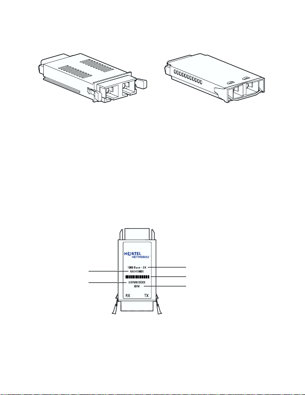
Figure 1 GBIC extraction tabs and extractor handle
GBIC model with
extractor tabs
GBIC model with
extractor handle
9702FA
GBIC labeling
The Nortel Networks label on a typical GBIC (Figure 2) contains
a Nortel Networks serial number, a bar code, a manufact urer’s
code, an interface type, and a part number.
Figure 2 Nortel Networks GBIC label
Part number
Serial number
3
GBIC interface type
Bar code
Manufacturer code
9706EA
Page 6
Note: When you contact a Nortel Networks service
representative for troubleshooting purposes, you must
have the following information available:
• Nortel Networks serial number
• Manufacturer’s code
• Interface type
• GBIC part number
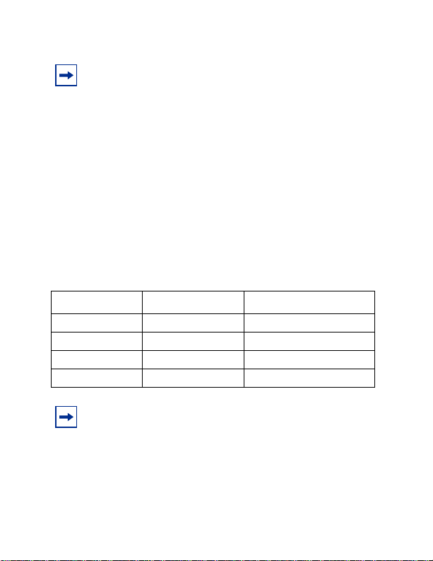
GBIC model list
Table 1 lists and describes the Nortel Networks GBIC models.
T able 1 Nortel Networks GBIC models
Model number Product number Description
1000BASE-SX AA1419001 Short wavelength 550 m
1000BASE-LX AA1419002 Long wavelength 5 km
1000BASE-XD AA1419003 Extended distance 50 km
1000BASE-ZX AA1419004 Extended distance 70 km
Note: GBIC wav elength distance may vary, depending
on the quality of fiber optic cable used.
4
Page 7

Handling, safety, and environmental guidelines
Before installing your GBIC, read the following hand ling, safety,
and environmental gui del ines:
• GBICs are static sensitive. To prevent damage from
electrostatic discharge (ESD), follow your normal board
and component handling proced ur es.
• GBICs are dust sensitive. When you store a GBIC, or when
you disconnect it from a fiber optic cable, always keep the
dust cover ov er the GB IC’s optical bores.
• To clean contaminants from the op t ical bores of a GBIC,
use an alcohol swab or equivalent to clean the ferrules of
the optical connector.
• Dispose of this product according to all national laws and
regulations.
Warning: Fiber optic equipment can emit laser or
infrared light that can i njure yo ur e yes. Never l ook i nto
an optical fiber or connector port. Always assume that
fiber optic cables are connecte d to a light source.
Installing a GBIC
This section lists the steps to install a GBIC.
T o install a GBIC:
1 Remove the GBIC from its protective packaging.
5
Page 8

2 Verify that the GBIC is the correct model for your network
configuration (Table 1 on page 4).
3 Remove the dust cover from the GBIC’s optical bores.
4 Grasp the GBIC between your thumb and forefinger.
5 Inser t the GBIC into the slot o n the fro nt pa nel of th e Gigab it
Ethernet switching module (Figure 3) .
Figure 3 Inserting the GBIC into th e sw i t ching module
Note: GBICs are keyed to prevent incorrect insertion.
Removing a GBIC
This section lists the steps for removing a GBIC.
To remove a GBIC:
1 Disconnect the network fiber cable from the GBIC
connector.
6
Page 9

2 Depending on your GBIC model, either grasp the extraction
tabs (Figure 1) located on either side of the GBIC with your
thumb and forefinger, or lift the extractor handle (Figure 1)
attached to the GBIC.
3 Slide the GBIC out of the Gigabit Ethernet module slot.
4 If the GBIC does not slide easily from the module slot, use a
gentle side-to-side rocking motion whil e firm ly pu llin g the
GBIC from the slot.
5 Dispose of the GBIC according to all national laws and
regulations.
Note: If you are storing a GBIC, remember to place a
dust cover over the fiber optic bores.
GBIC specifications
Table 2 describes general GBIC specifications.
T able 2 GBIC specifications
Specification Descriptions
Dimensions (H x W x D) 0.39 x 1.18 x 2.56 inches
(1 x 3 x 6.5 cm)
Connectors Multimode fiber optic: SC
Single-mode fiber optic: SC
7
Page 10

Standards, connectors, cabling, and distance
This section describes GBIC standards, connectors, cabling, and
distance; and provides specificat i ons for the following GBICs:
• “1000BASE-SX,” nex t
• “1000BASE-LX” on page 9
• “1000BASE-XD” on page 11
• “1000BASE-ZX” on page 13
GBIC ports for both multimode and single-mode fiber have
SC-type connectors and a minimum cable distance of 6.5 feet (2
m).
1000BASE-SX
The Model 1000BASE-SX GBIC provides 1000BASE-SX (850
nm, short wavelengt h, Gigabit Ethernet) connectivity using SC
duplex multimode fiber connectors.The Model 1000BASE-SX
GBIC supports full -duplex operati on only
Table 3 describes standards, connectors, cabling, and distance for
the Model 1000BASE-SX GBIC.
T able 3 1000BASE-SX specification s
Type Specifications
Standards Conformity to the following standards:
802.3z, 1000BASE-SX
Connectors Duplex SC fiber optic connector
.
8
Page 11

T able 3 1000BASE-SX specification s (cont inued)
Type Specifications
Cabling 62.5 µm MMF optic cable
50 µm MMF optic cable
Distance 902 ft. (275 m) using 62.5 µm
Wavelength 850 nm
Optical budget 7 dB
Laser Transmitter Characteristics
Minimum launch power -10 dBm
Maximum launch power -4 dBm
Receiver
Characteristics
Minimum receiver
sensitivity
Maximum input power 0 dBm
cable
1804 ft. (550 m) using 50 µm MMF optic cable
-17 dBm
MMF optic
1000BASE-LX
The Model 1000BASE-LX GBIC provides 1000BASE-LX
(1300 nm, wavelengt h, Gigabit Ether net) connectivity using
SC duplex fiber connectors. The long wavele ngth optical
transceivers used in the LX model provide variable distance
ranges using both multimode and single-mode fiber optic
cabling. The Model 1000BASE-LX GBIC supports full-duplex
operation only
.
9
Page 12

Table 4 describes standards, connectors, cabling, and distance for
the Model 1000BASE-LX GBIC.
T able 4 1000BASE-LX specification s
Type Specifications
Standards Conformity to the following standards:
802.3z, 1000BASE-LX
Connectors Duplex SC fiber optic connector
Cabling 62.5 µm
Distance 1804 ft. (550 m) using 62.5 µm
Wavelength 1300 nm
Optical budget 10.5 dB
Laser Transmitter Characteristics
Minimum launch power -9.5 dBm
Maximum launch power -3 dBm
Receiver Characteristics
Minimum receiver
sensitivity
Maximum input power -3 dBm
MMF optic cable
50 µm MMF optic cable
10 µm SMF optic cable
cable
1804 ft. (550 m) using 50 µm
16405 ft. (5 km) using 10 µm
-20 dBm
MMF optic
MMF optic cable
SMF optic cable
10
Page 13

Note: When multimode fiber is used in long-distance
applications, external, removable, mode-conditioning
patch cords may be required to prevent differential mode
delay (DMD). You can order mode conditioning patch
cords through Nortel Networks:
• SC-SC Mode-Conditioning Patch Cord 62. 5/125
(part number AA0018035)
• SC-SC Mode-Conditioning Patch Cord 50/12 5
(part number AA0018036)
1000BASE-XD
The Model 1000BASE-XD GBIC pr ovides Gigabit Ethernet
connectivity using SC duplex single-mode fiber connectors.
High-performance optical transceivers enable Gigabit Ethernet
link distances up to 50 kilometers (km) over single-mode fiber.
The ports operate in full-duplex mode only.
Note: The Model 1000BASE-XD GBIC is based on
proprietary signaling and is compatible with Accelar
1000 Series XD modules.
Table 5 describes standards, connectors, cabling, and distance for
the Model 1000BASE-XD GBIC.
T able 5 1000BASE-XD GBIC specific ati ons
Type Specifications
Standards Conformity to the following standards:
802.3z, Ethernet full duplex
11
Page 14

T able 5 1000BASE-XD GBIC specif icat ions (continued)
Type Specifications
Connectors Duplex SC single-mode fiber optic
Cabling Single-mode fiber optic cable
Distance Up to 50 km using single-mode fiber
Optical budget 17 dB
Laser Transmitter Characteristics
Wavelength 1550 ± 10 nm
Maximum spectral width 0.2 nm
Maximum launch power 0 dBm or 1.0 mW
Minimum launch power into
fiber
Distance 50 km
Receiver Characteristics
Wavelength 1200 to 1550 nm
Minimum receiver sensitivity -22 dBm
Maximum input power -3 dBm
connector
cable, depending on the quality of the fiber
-5 dBm or 0.3 mW
Note: Norte l Networks recommends that you use an
in-line attenuator for shorter link distances to avoid
overloading the receiver.
12
Page 15

1000BASE-ZX
The Model 1000BASE-ZX GB IC provides Gigabit Ethernet
connectivity using SC duplex single-mode fiber connectors.
High-performance optical transceivers enable Gigabit Ethernet
link distances up to 70 km over single-mode fiber cable. The
ports operate in full-duplex mode only.
Note: The 1000BASE-ZX Model GBIC is based on
proprietary signaling. Nortel Networks rec o mm e nds that
this product be used only with other Nortel Networks
1000BASE-ZX GBICs.
Table 6 describes standards, connectors, cabling, and distance for
the Model 1000BASE-ZX GBIC.
T able 6 1000BASE-ZX GBIC specifi cati on s
Type Specifications
Standards Conformity to the following standards:
Connectors Duplex SC single-mode fiber optic connector
Cabling Single-mode fiber cable
Distance Up to 70 km using single-mode fiber cable,
Optical Budget 22 dB
Laser Transmitter Characteristics
Wavelength 1550 ± 10 nm
Maximum spectral width 0.2 nm
Maximum launch power 5 dBm or 3.0 mW
Minimum launch power 0 dBm
802.3z, Ethernet full duplex
depending on the quality of the fiber
13
Page 16

T able 6 1000BASE-ZX GBIC specif icat ions (continued)
Type Specifications
Distance 70 km
Receiver Characteristics
Wavelength 1200 to 1550 nm
Minimum receiver sensitivity -22 dBm
Maximum input power -3 dBm
Note: When shorter lengths of si ngle-mode fiber cable
are used, there is a risk of overload i ng the receiver. It
may be necessary to insert an in-line optical attenuator
in the link to prevent overloading, as follows:
• Insert a 10 dB in-line optical attenuator between the
fiber optic cable plant and th e re ceiving port on the
1000BASE-ZX GB IC , at ea c h en d of the li nk , if the
fiber optic cable span is less than 25 km.
• Insert a 5 dB in line optical attenu at or between the
fiber optic cable plant and th e re ceiving port on the
1000BASE-ZX GB IC , at ea c h en d of the li nk , if the
fiber optic cable span is less than 50 km.
Connecting to Nortel Networks online
This section describes products, services, and support systems
that can be accessed online.
14
Page 17

Hard-copy technical manuals
You can print selected technical manuals and release notes free,
directly from the Internet. Go to the www.nortelnetworks.com/
documentation URL. Find the product for which you need
documentation. Then locate the speci fic category and model or
version for your hardware or software product. Use Adobe*
Acrobat Reader* to open the manuals and release notes, search
for the sections you need, and print them on most standard
printers. Go to Adobe Systems at the www.adobe.com URL to
download a free copy of the Adobe Acrobat Reader.
You can purchase selected documentation sets, CDs, and
technical publications t hrough the Internet at the
www1.fatbrain.com/documentation/nortel/ URL.
How to get help
If you purchased a service contract for your Nortel Networks
product from a distributor or authorized reseller, contact the
technical support staff for that distributor or reseller for
assistance.
If you purchased a Nortel Networks service program, contact one
of the following Nor tel Networks Technical Solutions Centers:
Technical Solutions Center Telephone
Europe, Middle East, and Africa (33) (4) 92-966-968
North America (800) 4NORTEL or (800) 466-7835
15
Page 18

Technical Solutions Center Telephone
Asia Pacific (61) (2) 9927-8800
China (800) 810-5000
An Express Routing Code (ERC) is available for many Nortel
Networks products and services. When you use an ERC, your
call is routed to a technical support person who specializ es in
supporting that product or service. To locate an ERC for your
product or service, go to the www12.nortelnetworks.com/ URL
and click ERC at the bottom of the page.
16
 Loading...