


 Loading...
Meridian 1
Option 11C and 11C Mini
Technical Reference Guide
Document Number: 553-3011-100
Document Release: Standard 14.00
Date: January 2002
Copyright © 1991–2002 Nortel Networks
All Rights Reserved
Printed in Canada
Information is subject to change without notice. Nortel Networks reserves the right to make changes in design or components as progress in engineering and manufacturing may warrant. This equipment has been tested and found to comply with the limits for a Class A digital device pursuant to Part 15 of the FCC rules, and the radio interference regulations of Industry Canada. These limits are designed to provide reasonable protection against harmful interference when the equipment is operated in a commercial environment. This equipment generates, uses and can radiate radio frequency energy, and if not installed and used in accordance with the instruction manual, may cause harmful interference to radio communications. Operation of this equipment in a residential area is likely to cause harmful interference in which case the user will be required to correct the interference at their own expense.
SL-1 and Meridian 1 are trademarks of Nortel Networks.

4
Page 3 of 544
Revision history
January 2002
Standard 14.00. This is a global document and is up-issued for Release 25.40.
December 2000
Standard 13.00. This global document is up-issued to include updates and changes required for Option 11C IP Expansion with Release 25.3x software.
April 2000
Standard 12.00. This is a global document and is up-issued for X11 Release 25.0x. Document changes include removal of: redundant content; references to equipment types except Options 11C and 11C Mini; and references to previous software releases.
September 1999
Issue 11.00, Standard
July 1999
Issue 10.00, Standard
May 1999
Issue 9.00, Standard
March 1998
Issue 8.00, Standard
July 1996
Release 7.00, Standard
July 1995
Release 6.00, Standard.
December 1994
Release 5.00, Standard.
Option 11C and 11C Mini Technical Reference Guide

Page 4 of 544
July 1994
Release 4.00, Standard.
October 1993
Release 3.00, Standard.
January 1993
Release 2.00, Issue 2.0, Standard.
April 1992
Release 2.00, Issue 1.0, Standard.
June 1991
Release 1.00, Standard.
553-3011-100 Standard 14.00 January 2002

8
Page 5 of 544
Contents
About this guide . . . . . . . . . . . . . . . . . . . . . . . . . . . 9
Chapter 1 — Memory, Storage and
CPU capacity . . . . . . . . . . . . . . . . . . . . . . . . . . . . . . 11
Chapter 2 — Provisioning . . . . . . . . . . . . . . . . . . . 87
Chapter 3 — Transmission parameters . . . . . . . . 157
Chapter 4 — Cabinet distribution over
a data network . . . . . . . . . . . . . . . . . . . . . . . . . . . . . 177 Chapter 5 — Spares planning . . . . . . . . . . . . . . . . 187 Chapter 6 — Power supplies . . . . . . . . . . . . . . . . . 197 Chapter 7 — System Controller cards . . . . . . . . . . 207 Chapter 8 — SDI ports . . . . . . . . . . . . . . . . . . . . . . 227 Chapter 9 — The TDS/DTR card . . . . . . . . . . . . . . . 243 Chapter 10 — NTBK22 MISP card . . . . . . . . . . . . . 261 Chapter 11 — Meridian Digital Telephones . . . . . 265 Chapter 12 — M2317 Telephone . . . . . . . . . . . . . . 271 Chapter 13 — Meridian Modular Telephones . . . . 283
Option 11C and 11C Mini Technical Reference Guide

Page 6 of 544 Contents
Chapter 14 — M3900 telephone series . . . . . . . . . 309
Chapter 15 — European Digital
telephones: 3110, 3310, and 3820 . . . . . . . . . . . . . 319 Chapter 16 — M5317 BRI Terminal . . . . . . . . . . . . 335 Chapter 17 — M2250 Attendant Console . . . . . . . 353
Chapter 18 — NT8D02 and NTDK16
Digital Line Cards . . . . . . . . . . . . . . . . . . . . . . . . . . 365
Chapter 19 — NT8D09 Analog Message
Waiting Line Card . . . . . . . . . . . . . . . . . . . . . . . . . . 371 Chapter 20 — NT8D14 Universal Trunk Card . . . . 377 Chapter 21 — NT8D15 E&M Trunk Card . . . . . . . . 389 Chapter 22 — NT5K21 XMFC/MFE card . . . . . . . . 399 Chapter 23 — NTAG26 XMFR card . . . . . . . . . . . . 409 Chapter 24 — NT6D70 SILC line card . . . . . . . . . . 415 Chapter 25 — NT6D71 UILC line card . . . . . . . . . . 419
Chapter 26 — NT1R20 Off Premise
Station (OPS) analog line card . . . . . . . . . . . . . . . 423 Chapter 27 — Cable specifications and interfaces 439 Chapter 28 — NTAK09 1.5 Mb DTI/PRI card . . . . . 447
Chapter 29 — NTRB21 DTI/PRI/DCH
TMDI card . . . . . . . . . . . . . . . . . . . . . . . . . . . . . . . . 455 Chapter 30 — NTAK10 2.0 Mb DTI card . . . . . . . . 467
553-3011-100 Standard 14.00 January 2002

Contents Page 7 of 544
Chapter 31 — NTAK79 2.0 Mb PRI card . . . . . . . . 479 Chapter 32 — NTBK50 2.0 Mb PRI card . . . . . . . . 493 Chapter 33 — NTAK20 clock controller . . . . . . . . 503
Chapter 34 — NTAK93 D-channel handler
interface . . . . . . . . . . . . . . . . . . . . . . . . . . . . . . . . . . 513
Chapter 35 — NTBK51 Downloadable
D-channel handler . . . . . . . . . . . . . . . . . . . . . . . . . . 519 Chapter 36 — NT5D14 Line Side T-1 card . . . . . . . 525 List of terms . . . . . . . . . . . . . . . . . . . . . . . . . . . . . . . 531 Index . . . . . . . . . . . . . . . . . . . . . . . . . . . . . . . . . . . . 537
Option 11C and 11C Mini Technical Reference Guide

Page 8 of 544 Contents
553-3011-100 Standard 14.00 January 2002

10
Page 9 of 544
About this guide
This Technical Reference guide contains detailed technical information about the Option 11C and Option 11C Mini systems. It includes such things as:
•circuit cards information
•spares planning
•SDI ports information
•tones and cadences
•transmission parameters
•Meridian modular telephone sets
•M2250 attendant console
This document is a global document. Contact your system supplier or your Nortel Networks representative to verify that the hardware and software described is supported in your area.
Option 11C and 11C Mini Technical Reference Guide

Page 10 of 544 About this guide
553-3011-100 Standard 14.00 January 2002
86
Page 11 of 544
Chapter 1 — Memory, Storage and
CPU capacity
Contents
This section contains information on the following topics:
Reference List . . . . . . . . . . . . . . . . . . . . . . . . . . . . . . . . . . . . . . . . . . . . 12
Overview . . . . . . . . . . . . . . . . . . . . . . . . . . . . . . . . . . . . . . . . . . . . . . . 12
Option 11C and Option 11C Mini data storage, loading, and restoring . . 12
Data storage . . . . . . . . . . . . . . . . . . . . . . . . . . . . . . . . . . . . . . . . . . . . . . 14
Data loading . . . . . . . . . . . . . . . . . . . . . . . . . . . . . . . . . . . . . . . . . . . . . . 16
Data restoring . . . . . . . . . . . . . . . . . . . . . . . . . . . . . . . . . . . . . . . . . . . . . 18
Pre-programmed data . . . . . . . . . . . . . . . . . . . . . . . . . . . . . . . . . . . . . . . 18
Components of pre-programmed data . . . . . . . . . . . . . . . . . . . . . . . . . . 19
Model telephones . . . . . . . . . . . . . . . . . . . . . . . . . . . . . . . . . . . . . . . . . . 19
Trunk route data and model trunks . . . . . . . . . . . . . . . . . . . . . . . . . . . . 20
Numbering plan . . . . . . . . . . . . . . . . . . . . . . . . . . . . . . . . . . . . . . . . . . . 20
SDI ports . . . . . . . . . . . . . . . . . . . . . . . . . . . . . . . . . . . . . . . . . . . . . . . . 21
Tone services . . . . . . . . . . . . . . . . . . . . . . . . . . . . . . . . . . . . . . . . . . . . . 21
Benefits of pre-programmed data . .. . . . . . . . . . . . . . . . . . . . . . . . . . . . 21
Software Installation program and pre-programmed data . . . . . . . . . . . 22
Removing pre-programmed data . . . . . . . . . . . . . . . . . . . . . . . . . . . . . . 23
Customer Configuration Backup and Restore . . . . . . . . . . . . . . . . . . . . 23
Operations performed . .. . . . . . . . . . . . . . . . . . . . . . . . . . . . . . . . . . . . . 23
File transfer time . . . . . . . . . . . . . . . . . . . . . . . . . . . . . . . . . . . . . . . . . . 24
Option 11C and 11C Mini Technical Reference Guide

Page 12 of 544 Memory, Storage and CPU capacity
Equipment requirements . . . . . . . . . . . . . . . . . . . . . . . . . . . . . . . . . . . . . 24 Real time CPU capacity . .. . . . . . . . . . . . . . . . . . . . . . . . . . . . . . . . . . . . 25 Software Program store . . . . . . . . . . . . . . . . . . . . . . . . . . . . . . . . . . . . . . 28 Resident Program store . . . . . . . . . . . . . . . . . . . . . . . . . . . . . . . . . . . . . . 28 Data store requirements . . . . . . . . . . . . . . . . . . . . . . . . . . . . . . . . . . . . . . 30 Unprotected data requirements . . . . . . . . . . . . . . . . . . . . . . . . . . . . . . . . 30 Notes to Table 11 . .. . . . . . . . . . . . . . . . . . . . . . . . . . . . . . . . . . . . . . . . . 34 Protected data requirements . . . . . . . . . . . . . . . . . . . . . . . . . . . . . . . . . . . 48 Notes for Table 12 . . . . . . . . . . . . . . . . . . . . . . . . . . . . . . . . . . . . . . . . . . 53
Reference List
The following are the references in this section:
•Maintenance (553-3001-511)
•Option 11C Customer Controlled Backup and Restore (CCBR) (553- 3011-330)
•Option 11C Mini Planning and Installation (553-3021-209)
•Option 11C Planning and Installation (553-3021-210)
•Option 11C and 11C Mini Upgrade Procedures (553-3021-250)
Overview
This chapter presents an outline of Real Time CPU capacity for the
Option 11C, and Option 11C Mini. In addition, it describes Option 11C and Option 11C Mini data storage, loading and restoring, as well as the unprotected and protected memory requirements for features applicable to the these systems.
Option 11C and Option 11C Mini data storage, loading, and restoring
For the Option 11C and Option 11C Mini system, configuration data is both stored and loaded by accessing overlay programs 43 and 143. The sequence of events where data is copied from one area to the next depends on the status of the switch - new installation, software upgrade - and the purpose of the data transfer, such as to make a backup copy of the customer database.
553-3011-100 Standard 14.00 January 2002

Memory, Storage and CPU capacity Page 13 of 544
An Option 11C with IP Expansion can be made up of both Option 11C cabinets and Option 11C Mini chassis. However, when an Option 11C Mini chassis is used, the NTDK97 Mini System Controller (MSC) card is replaced with an NTDK20 Small System Controller (SSC) card and an appropriate IP Expansion daughterboard.
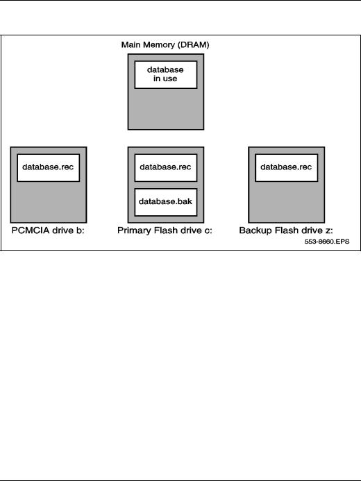
Option 11C and Option 11C Mini software is stored in various areas of the NTDK20 SSC and NTDK97 MSC cards. In terms of customer data, there are four possible areas where these records can be stored (Refer to Figure 1):
•DRAM — stores and accesses the active version of customer records, system data and overlay data
•Primary Flash drive c: — contains two copies of customer records (primary and backup records)
•Backup Flash drive z: — retains the true backup copy of the customer database
•PCMCIA device a: or b: — if equipped, this 40 Mbyte device can store a complete backup copy of the customer database
Option 11C and 11C Mini Technical Reference Guide

Page 14 of 544 Memory, Storage and CPU capacity
Data storage
The Option 11C and 11C Mini data dump performed in LD 43, is the system’s method of backing up configuration data to its file storage devices. By invoking one of the several data dump commands in the overlay, the user is ensured that at least one backup copy of configuration data exists in a location other than DRAM (Refer to Table 1).
Table 1
LD 43 data dump commands
Command |
|
Description |
|
|
|
BKO |
|
Customer records in the Primary Flash drive are copied to the PCMCIA |
|
|
device. |
EDD |
|
Customer data in DRAM is written to the Primary and Backup flash drives |
|
|
on the NTDK20 SSC and NTDK97 MSC. |
EDD NBK |
|
Customer data in DRAM is written to the Primary and Backup flash drives |
|
|
on the NTDK20 SSC and NTDK97 MSC. (Same as the EDD command). |
SWP |
|
A swap or exchange of database records is completed between the Pri- |
|
|
mary Flash drive’s main and secondary databases (Refer to Figure 1). |
|
|
|
|
The effects of the LD 43 commands described above are be better illustrated |
|
|
by referring to Figure 1. |
|
|
|
Note: Refer to the Option Maintenance (553-3001-511) for a complete |
|
|
listing and description of LD 43 commands. |
553-3011-100 Standard 14.00 January 2002
Memory, Storage and CPU capacity Page 15 of 544
Figure 1
Data storage on the NTDK20 SSC and NTDK97 MSC
The Option 11C and Option 11C Mini offer one additional area of data storage that is truly external to the switch. This storage device can be an IBMtype PC or Macintosh-type computer, running an Option11C software feature called “Customer Configuration Backup and Restore” (CCBR). Through the use of LD 143 and the CCBR feature, the user can transfer customer records between the SSC or MSC’s Primary Flash drive to either an on-site or remotecomputer system (Refer to Table 2 for a listing of CCBR commands supported in LD 143).
Option 11C and 11C Mini Technical Reference Guide

Page 16 of 544 Memory, Storage and CPU capacity
Table 2
LD 143 CCBR commands
Command |
Description |
|
|
XBK |
Customer database records in the Primary Flash drive are backed up to |
|
an external computer hard-drive. |
XRT |
Customer database records are restored from an external computer |
|
hard-drive to the Backup Flash drive and on the NTDK20 SSC and |
|
NTDK97 MSC. |
XSL |
The Option 11C or Option 11C Mini is remotely “sysloaded” with cus- |
|
tomer records stored in the Primary Flash drive. |
XVR |
Customer files stored on an external computer are verified for validity and |
|
integrity with records in the Backup Flash drive. |
|
|
Note: Refer to Administration (553-3001-311) and Maintenance (553- 3001-511) for a complete listing and description of LD 143 commands.
Data loading
An Option 11C and 11C Mini “SYSLOAD” is a sequence of events whereby the switch loads and verifies system and customer records into the NTDK20 SSC’s or NTDK97 MSC’s active memory area, or DRAM. The flow of data depends on the status of the software - new installation, software release upgrade, or a user-initiated sysload - or the commands initiated in either LD 143, or the Install Setup Program.
Despite the various ways to initiate a Sysload, the flow of data generally follows the path described below (Refer to Figure 2 for a graphical illustration):
1The Option 11C and 11C Mini searches for customer records in the Primary Flash drive. If the files are located and verified, data is loaded into the NTDK20 SSC’s or NTDK97 MSC’s DRAM.
2If the records are corrupt or cannot be found in the Primary Flash drive, the system searches the Backup Flash drive. If the customer records are located and verified, the Option 11C and 11C Mini loads the data into DRAM.
553-3011-100 Standard 14.00 January 2002

Memory, Storage and CPU capacity Page 17 of 544
3If the customer records cannot be located in the Backup Flash drive, the Option 11C and 11C Mini automatically searches the PCMCIA drive. If customer records are located and verified, data is loaded into DRAM.
4If the customer records cannot be located in the PCMCIA drive, the Option 11C and 11C Mini searches the Primary Flash drive for the secondary backup (.bak) file. If the customer records are located and verified, data is loaded into DRAM.
Figure 2
Flow of data during an Option 11C or Option 11C Mini Sysload
Sysload and a new Option 11C or Option 11C Mini installation
Software for new Option 11C and 11C Mini systems is delivered on a preprogrammed Software Daughterboard for the Option 11C, or directly on the MSC for the Option 11C Mini. Once this hardware is installed and the system is powered up (SYSLOAD), the Install Setup and Loader program (LD 143) is automatically invoked. This program is menu driven and assists in loading the software into the system.
Option 11C and 11C Mini Technical Reference Guide

Page 18 of 544 Memory, Storage and CPU capacity
Data restoring
In the unlikely event configuration data becomes corrupted, a backup copy of the current database can be restored to the Option 11C and 11C Mini. There are four possible areas of where a backup of configuration data can be restored from — the secondary primary database, the backup flash drive, the PCMCIA drive, or an external computer hard-drive. (Refer to Table 2 for a description of the commands used to restore backup data to the Option 11C and 11C Mini.)
Table 3
Commands used to restore data to the Option 11C and Option 11C Mini
Command |
Overlay |
Description |
|
|
|
SWP |
43 |
Secondary primary files are “swapped” with the contents of |
(see note) |
|
the primary flash drive (Refer to database.bak in Figure 2). |
RES |
43 |
Restore files to the primary flash drive from the PCMCIA |
|
|
drive. |
RIB |
43 |
Restores the missing files in primary flash drive from the |
|
|
internal backup drive. |
XRT |
143 |
Customer database records are restored from an external |
|
|
computer hard-drive to the Primary and Backup Flash drives |
|
|
on the NTDK20 SSC or NTDK97 MSC. |
|
|
|
Note: The SWP command in LD 43 does not “restore” data to the primary flash drive: it swaps or replaces the contents of the primary drive with the data stored in the primary drive’s secondary database.
Pre-programmed data
When an Option 11C or Option 11C Mini system is initially installed, customer data must be entered into the overlay programs. Telephones, for example, must be assigned features on their keys to allow them to function properly.
However, the Main SSC or the Mini MSC can be pre-programmed with customer data. If you load pre-programmed data into the system during installation, some overlay entries will be automatically configured on the telephones. For example, you can choose a telephone model that has predetermined feature and key assignments and a preassigned class of
553-3011-100 Standard 14.00 January 2002

Memory, Storage and CPU capacity Page 19 of 544
service. This can be a significant time-saver if you have to program numerous types of telephone models.
Pre-programmed data is not mandatory for software installation. In fact, the NTDK20 or the NTDK97, can be programmed with the minimum number of files to allow the Option 11C and 11C Mini to operate.
During start-up, the Software Installation Program is automatically invoked. The Option 11C or Option 11C Mini, loads system data from the NTDK20, or the NTDK97 respectively, and prompts the user for a variety of information, including the time and date, type of installation, feature set required, and type of database. At this point, if the user selects any response other than “Default database,” pre-programmed data will not be loaded on the system.
Pre-programmed data cannot be removed from the Option 11C and 11C Mini system once it is loaded into the system. However, pre-programmed data can be bypassed during first-time system installations.
Note: The pre-programmed data on the Option 11C and 11C Mini system can provide an effective starting point for programming telephone and trunk information. Before bypassing the option of loading pre-programmed data, take the time to determine whether the default data can be used at this site.
Components of pre-programmed data
The following items are pre-programmed in the Default database on the Main Option 11C NTTK13 Software Daughterboard:
•Model telephones
•Trunk route data and model trunks
•Numbering plan
•SDI ports
•Tone and digit switch
Model telephones
A model telephone can be thought of as a default set of features and class of service assigned to a telephone.
Option 11C and 11C Mini Technical Reference Guide

Page 20 of 544 Memory, Storage and CPU capacity
Telephone models simplify telephone installation. During telephone activation, the telephone prompts you to accept a default model. If a model is chosen, all keys are automatically assigned a feature and no further key programming is required. (The extension number is also predefined using the default numbering plan.)
If you do not want to accept the default model, you can create other models by following the procedures in Chapter 19 of the Option 11C Planning and Installation (553-3021-210), or Chapter 17 of the Option 11C Mini Planning and Installation (553-3021-209).
Note: Off-Premise Station (OPS) telephones do not have their own telephone models. You can, however, create OPS models by entering DD in response to the CDEN prompt in LD 10.
Trunk route data and model trunks
Pre-programmed trunk routes and trunk models simplify trunk installation procedures. A pre-programmed trunk route supports a certain trunk type, has a default access code, and must be assigned a trunk model. A trunk model supports a certain card type, trunk type, and signalling arrangement.
Trunk models are assigned to default trunk routes using the administration telephone. You can create other models by following the procedures in Chapter 20 of the Option 11C Planning and Installation (553-3021-210) or Chapter 18 of the Option 11C Mini Planning and Installation (553-3021- 209).
Numbering plan
The pre-programmed numbering plan automatically assigns default extension numbers to the following (this list may not be representative of all countries):
•Local extension numbers
•Attendant extension
•Night number
•ACD queues
•Meridian Mail extensions
•Call park extensions
553-3011-100 Standard 14.00 January 2002
Memory, Storage and CPU capacity Page 21 of 544
If the default numbering plan does not suit this system’s needs, you can change it using the procedures Chapter 22 of the Option 11C Planning and Installation (553-3021-210) or Appendix A of the Option 11C Mini Planning and Installation (553-3021-209).
SDI ports
There are three pre-programmed SDI ports on Option 11C and 11C Mini systems. The NTDK20 SSC or NTDK97 MSC provides TTY ports 0, 1, and 2. All three SDI interfaces can be used as either modem or maintenance ports for TTY terminals.
Tone services
The SSC/MSC provides 30 channels of tone and cadence transmission to the system.
The SSC/MSC also provides tone detection. Units 0-7 can be configured to support DTR/XTD. Units 8-15 can also be configured to support DTR/XTD
Optionally, units 8-11 can be configured to support other tone detection functions in lieu of DTR/XTD on units 8-15. These other tone functions include one of MFC/MFE/MFK5/MFK6/MFR.
LD 56 contains default tables used for tone and cadence generation.
Table 4
LD 56 tone and cadence data
|
Pre-configured TDS/DTR data |
|
|
|
|
TDS loop |
|
Channels 1-30 |
DTR or XTD |
|
Card 0, units 0-7 |
|
|
|
Benefits of pre-programmed data
The main benefit of pre-programmed data is that it simplifies installation and activation procedures. Table 5 compares how a task would be performed using pre-programmed data and how it would be performed without preprogrammed data.
Option 11C and 11C Mini Technical Reference Guide

Page 22 of 544 |
Memory, Storage and CPU capacity |
||
|
|
|
|
Table 5 |
|
|
|
Benefits of pre-programmed data |
|
||
|
|
|
|
Task |
Task performed using pre- |
Task performed without using |
|
programmed data |
pre-programmed data |
||
|
|||
|
|
|
|
Activating |
Plug telephone into socket, lift |
Enter LD 10 or 11, enter telephone type, |
|
telephones |
handset, choose model, |
specify TN, assign class of service, assign |
|
|
choose extension |
a feature to each key on telephone |
|
|
|
LD 10 has approximately 120 prompts |
|
|
|
LD 11 has approximately 160 prompts |
|
|
|
|
|
Activating |
Use the administration menu |
Enter LD 16, enter trunk type, access code, |
|
trunks |
to add a trunk: |
signalling arrangements |
|
|
• enter a route access code |
Enter LD 14, enter TN, route member |
|
|
• enter a TN |
||
|
number, signalling arrangements, class of |
||
|
• enter a trunk model |
||
|
service, and so on |
||
|
|
||
|
|
LD 16 has approximately 200 prompts |
|
|
|
LD 14 has approximately 50 prompts |
|
|
|
|
|
Establishing a |
No effort required. Default |
A numbering plan must be developed to |
|
numbering |
extension numbers become |
map TNs to DNs. |
|
plan |
active when telephones are |
|
|
|
activated. Default plan is |
|
|
|
sequential. |
|
|
|
|
|
|
Software Installation program and pre-programmed data
The Software Installation program is automatically invoked when the new Option 11C or Option 11C Mini is started up (SYSLOAD). After successfully responding to various prompts in the program, you are given the option of selecting a database to be loaded.
Detailed information about the Software Installation program can be found in the Option 11C Planning and Installation (553-3021-210) or the Option 11C Mini Planning and Installation (553-3021-209) used for first-time installations; or the Option 11C and 11C Mini Upgrade Procedures (553- 3021-250) used for upgrades from an Option 11 or 11E to an Option 11C system.
553-3011-100 Standard 14.00 January 2002

Memory, Storage and CPU capacity Page 23 of 544
Removing pre-programmed data
Pre-programmed data cannot be removed from the Option 11C or Option 11C Mini system once it is loaded into the system. However, pre-programmed data can be bypassed during first-time system installations.
During start-up, the Software Installation Program is automatically invoked. The Option 11C and 11C Mini then loads system data from the Software Daughterboard, or MSC for the Option 11C Mini, and prompts the user for a variety of information, including the time and date, type of installation, feature set required, and type of database. At this point, if the user selects any response other than “Default database,” pre-programmed data will not be loaded on the system
Note: The pre-programmed data on the Option 11C and 11C Mini system can provide an effective starting point for programming telephone and trunk information. Before bypassing the option of loading pre-programmed data, take the time to determine whether the default data can be used at this site.
Customer Configuration Backup and Restore
The Customer Configuration Backup and Restore (CCBR) feature provides the ability to store the configuration database of the Option 11C on an external hard-drive of an IBM-type PC or Macintosh-type computer.
The CCBR feature can be invoked on-site with the use of a modem eliminator, or remotely over a modem connection.
Operations performed
The CCBR feature performs two different functions of safeguarding customer programmed data. The first involves storing the configuration database in the unlikely event of an system failure - such as a continuous SYSLOAD or INI - or data corruption. To correct this problem, the backup copy of the configuration database can be restored to the Option 11C or Option 11C Mini.
Option 11C and 11C Mini Technical Reference Guide

Page 24 of 544 Memory, Storage and CPU capacity
The second function of the CCBR feature has to do with the role it plays in upgrading software from an Option 11 or 11E to an Option 11C system. To illustrate, if the CCBR feature is invoked in LD 43 of an Option 11 or 11E, its configuration data can be backed up on a hard-drive of an external computer. When the new Option 11C hardware is fully installed, and the PCMCIA card is inserted in the System Core card, the backup copy of the configuration data - stored on the computer - can be transferred back to the upgraded Option 11C system as part of the software upgrade process. Immediately upon download, the Option 11 or 11E database files will be automatically converted to the Option 11C format.
Note: Whenever the CCBR feature is used, configuration data is always backed up to the primary flash drive. Prior to invoking the CCBR command, a data dump should be performed to ensure the primary database is current.
File transfer time
Depending on the number of records in the configuration data base, it can take over 30 minutes to backup or restore data at a rate of 1200 bps. CCBR access time can be significantly decreased using a 19200 baud modem: 19200 baud is the maximum data transfer rate supported by the Option 11C or Option 11C Mini.
Equipment requirements
Communications software
Communications software compatible with XModem CRC protocol is required to operate the CCBR feature. This requirement applies to on-site and remote access.
On-site access
On-site access to the Option 11C or Option 11C Mini system can be made by directly connecting a computer to SDI port 0, 1, or 2.
Note: You will need to connect a modem eliminator between the SDI cable and the computer cable for on-site computer access.
553-3011-100 Standard 14.00 January 2002

Memory, Storage and CPU capacity Page 25 of 544
Remote access
Remote access to the Option 11C or Option 11C Mini is established by connecting SDI port 0, 1, or 2 on the SSC/MSC to an analog line (Central Office line) through an on-site modem. This will allow the computer to dial directly into the Option 11C or Option 11C Mini from a remote location.
Detailed information about the CCBR feature can be found in the Option 11C Customer Controlled Backup and Restore (CCBR) (553-3011-330).
Real time CPU capacity
Table 6
CPU capacity
Release |
Average Msecs of CPU for PBX Call |
Equivalent Basic IPE Calls per |
|
(Equivalent Basic Call) |
Hour |
||
|
|||
|
|
|
|
16.90G |
250 |
10075 |
|
18.30H |
306 |
8225 |
|
18.40H |
300 |
8400 |
|
20.06 |
338 |
7450 |
|
20.19 |
374 |
6750 |
|
21.0x |
373 |
6075 |
|
22.0x |
50 |
58000 |
|
23 |
50 |
55775 |
|
24 |
47 |
50175 |
|
25 |
49 |
46324 |
|
|
|
|
Option 11C and 11C Mini Technical Reference Guide

Page 26 of 544 Memory, Storage and CPU capacity
Table 7
Option 11C Real Time Measurements PRI Calls (msecs) (with IP Expansion)
Call Type |
2527d(2530) No Expansion cabinet |
|
2527d (2530) With IP Expansion |
|
cabinet |
||
|
|
|
|
|
|
|
|
pbx - tie |
57 |
|
89 |
tie - pbx |
51 |
|
86 |
aries - tie |
56 |
|
127 |
tie - aries |
59 |
|
99 |
tie - tie |
|
|
|
Average |
58 |
|
100 |
|
|
|
|
Figure 3 |
|
|
|
Option 11C Real Time Measurements i2004 Calls (msecs) |
|
||
|
ITG card on Expansion cabinet |
ITG card on Main cabinet |
Call Type |
PRI card on Expansion cabinet |
PRI card on Expansion cabinet |
|
2527d |
2527d |
|
|
|
i2004-aries |
236 |
231 |
aries-i2004 |
197 |
190 |
i2004-i2004 |
323 |
321 |
i2004-tie |
319 |
321 |
|
|
|
Option 11C memory requirements are calculated using the following tables:
•Table 9 on page 28 - Resident Program Store
•Table 10 on page 29 - IP Memory Impacts
•Table 11 on page 30 - Unprotected data store requirements
•Table 12 on page 48 - Protected data store requirements
553-3011-100 Standard 14.00 January 2002

Memory, Storage and CPU capacity Page 27 of 544
Record the memory requirements on “Worksheet D: Unprotected memory calculations” on page 141 and “Worksheet E: Protected memory calculations” on page 142.
Network Delay
There is some impact on real-time performance (estimated to be 20%) when digital trunks are installed in IP Expansion cabinets. However, there is still sufficient real-time to support five fully configured Option 11C cabinets in a typical business configuration.
Table 8
Basic LAN Requirements for Excellent Voice Quality
LAN requirement |
Value for Excellent Voice Quality |
|
|
Packet loss rate |
<0.5% |
PDV jitter buffer (maximum) |
RTD<5 ms |
Round trip Delay |
<5 ms |
PDV jitter buffer (minimum) |
RTD<12 ms |
100BaseT/F Layer 2/Layer 3 switch |
Full Duplex connection |
|
|
Option 11C and 11C Mini Technical Reference Guide

Page 28 of 544 Memory, Storage and CPU capacity
Software Program store
Resident Program store
The Resident Program store requirements are listed in Table 9
Table 9
Resident Program Store
Program 1024 words = 1K |
Storage in words |
|
|
Basic (BASE) |
0 |
Read/Write Firmware |
0 |
Overlay |
46 000 |
Options (OPTF) |
0 |
Multi Customer (CUST) |
0 |
ROM Firmware |
8 000 |
Total |
54 000 |
|
|
553-3011-100 Standard 14.00 January 2002

Memory, Storage and CPU capacity Page 29 of 544
For IP connectivity, extra memory usage is required. Table 10 summarizes the additional memory requirements of the Survivable IP configuration.
Table 10
IP Memory impacts
Functional area |
Flash |
DRAM |
C-drive |
PCMCIA |
|
|
|
|
|
CDR storage |
|
|
4 Mb (17500) |
|
Survivable db |
|
x |
x |
x |
start-up |
3K |
2K |
|
3K |
100baseT/F |
|
|
|
218981 B |
multi-clock |
28 words |
|
|
|
cardlan |
|
30K |
|
|
SSD |
|
40K |
|
|
IP config |
|
0.8K |
0.8K |
0.8K |
voice |
|
1K |
|
|
bootP |
|
20K |
0.8K |
0.8K |
remote TTY |
|
35K |
|
|
TOTAL |
|
|
|
|
|
|
|
|
|
Option 11C and 11C Mini Technical Reference Guide

Page 30 of 544 Memory, Storage and CPU capacity
Data store requirements
Unprotected data requirements
Table 11 lists the unprotected data store requirements per item in words.
Table 11
Unprotected data store requirements (Part 1 of 4)
Data Store by Feature |
Fixed Number of 1k |
Calculated number |
|
Words per Item |
of Words Per Item |
||
|
|||
|
|
|
|
Fixed Address Globals |
22389 |
- |
|
500-type telephones |
8.5 |
- |
|
2500-type telephones |
8.5 |
- |
|
SL-1 sets (no digit display) |
20.25 |
- |
|
SL-1 sets (digit display) |
22.25 |
- |
|
Add-on K/L Strips |
10 |
- |
|
Data Service/VMS Access TNs |
- |
See Note 10 on page |
|
|
|
40 |
|
Analog Trunks |
- |
See Note 17 on page |
|
|
|
44 |
|
BRI Trunks |
83 |
- |
|
DTI |
82 |
- |
|
JDM/DTI2 |
57 |
- |
|
ISDN PRI/PRI2/ISL |
- |
See Note 18 on page |
|
|
|
46 |
|
Attendant |
131 |
- |
|
Customers |
234 |
- |
|
Console Presentation Group (CPG) Data |
29, 35 |
#Customer, #CPG |
|
Block |
|
|
|
Trunk Routes |
- |
See Note 1 on page |
|
|
|
34 |
|
|
|
|
553-3011-100 Standard 14.00 January 2002
Loading...