

Page 1

Nortel Ethernet Routing Switch 2500 Series
Overview — System
Configuration
NN47215-500 (323162-B)
.
Page 2

Document status: Standard
Document version: 02.02
Document date: 19 November 2007
Copyright © 2007, Nortel Networks
All Rights Reserved.
Sourced in Canada, India, and the United States of America
The information in this document is subject to change without notice. The statements, configurations, technical
data, and recommendations in this document are believed to be accurate and reliable, but are presented without
express or implied warranty. Users must take full responsibility for their applications of any products specified in this
document. The information in this document is proprietary to Nortel Networks.
The software described in this document is furnished under a license agreement and may be used only in accordance
with the terms of that license. The software license agreement is included in this document.
Trademarks
*Nortel, Nortel Networks, the Nortel logo, and the Globemark are trademarks of Nortel Networks.
Adobe and Adobe Reader are trademarks of Adobe Systems Incorporated.
Microsoft, Windows, and Windows NT are trademarks of Microsoft Corporation.
Trademarks are acknowledged with an asterisk (*) at their first appearance in the document.
All other trademarks are the property of their respective owners.
Restricted rights legend
Use, duplication, or disclosure by the United States Government is subject to restrictions as set forth in subparagraph
(c)(1)(ii) of the Rights in Technical Data and Computer Software clause at DFARS 252.227-7013.
Notwithstanding any other license agreement that may pertain to, or accompany the delivery of, this computer
software, the rights of the United States Government regarding its use, reproduction, and disclosure are as set forth
in the Commercial Computer Software-Restricted Rights clause at FAR 52.227-19.
Statement of conditions
In the interest of improving internal design, operational function, and/or reliability, Nortel Networks reserves the right
to make changes to the products described in this document without notice.
Nortel Networks does not assume any liability that may occur due to the use or application of the product(s) or
circuit layout(s) described herein.
Portions of the code in this software product may be Copyright © 1988, Regents of the University of California. All
rights reserved. Redistribution and use in source and binary forms of such portions are permitted, provided that the
above copyright notice and this paragraph are duplicated in all such forms and that any documentation, advertising
materials, and other materials related to such distribution and use acknowledge that such portions of the software
were developed by the University of California, Berkeley. The name of the University may not be used to endorse or
promote products derived from such portions of the software without specific prior written permission.
SUCH PORTIONS OF THE SOFTWARE ARE PROVIDED "AS IS" AND WITHOUT ANY EXPRESS OR IMPLIED
WARRANTIES, INCLUDING, WITHOUT LIMITATION, THE IMPLIED WARRANTIES OF MERCHANTABILITY AND
FITNESS FOR A PARTICULAR PURPOSE.
In addition, the program and information contained herein are licensed only pursuant to a license agreement that
contains restrictions on use and disclosure (that may incorporate by reference certain limitations and notices
imposed by third parties).
Page 3

Nortel Networks software license agreement
This Software License Agreement ("License Agreement") is between you, the end-user ("Customer") and Nortel
Networks Corporation and its subsidiaries and affiliates ("Nortel Networks"). PLEASE READ THE FOLLOWING
CAREFULLY. YOU MUST ACCEPT THESE LICENSE TERMS IN ORDER TO DOWNLOAD AND/OR USE THE
SOFTWARE. USE OF THE SOFTWARE CONSTITUTES YOUR ACCEPTANCE OF THIS LICENSE AGREEMENT.
If you do not accept these terms and conditions, return the Software, unused and in the original shipping container,
within 30 days of purchase to obtain a credit for the full purchase price.
"Software" is owned or licensed by Nortel Networks, its parent or one of its subsidiaries or affiliates, and is
copyrighted and licensed, not sold. Software consists of machine-readable instructions, its components, data,
audio-visual content (such as images, text, recordings or pictures) and related licensed materials including all whole
or partial copies. Nortel Networks grants you a license to use the Software only in the country where you acquired the
Software. You obtain no rights other than those granted to you under this License Agreement. Youare responsible for
the selection of the Software and for the installation of, use of, and results obtained from the Software.
Licensed Use of Software. Nortel Networks grants Customer a nonexclusive license to use a copy of the
1.
Software on only one machine at any one time or to the extent of the activation or authorized usage level,
whichever is applicable. To the extent Software is furnished for use with designated hardware or Customer
furnished equipment ("CFE"), Customer is granted a nonexclusive license to use Software only on such
hardware or CFE, as applicable. Software contains trade secrets and Customer agrees to treat Software as
confidential information using the same care and discretion Customer uses with its own similar information that it
does not wish to disclose, publish or disseminate. Customer will ensure that anyone who uses the Software
does so only in compliance with the terms of this Agreement. Customer shall not a) use, copy,modify, transfer or
distribute the Software except as expressly authorized; b) reverse assemble, reverse compile, reverse engineer
or otherwise translate the Software; c) create derivative works or modifications unless expressly authorized; or d)
sublicense, rent or lease the Software. Licensors of intellectual property to Nortel Networks are beneficiaries of
this provision. Upon termination or breach of the license by Customer or in the event designated hardware or
CFE is no longer in use, Customer will promptly return the Software to Nortel Networks or certify its destruction.
Nortel Networks may audit by remote polling or other reasonable means to determine Customer’s Software
activation or usage levels. If suppliers of third party software included in Software require Nortel Networks to
include additional or different terms, Customer agrees to abide by such terms provided by Nortel Networks
with respect to such third party software.
2. Warranty. Except as may be otherwise expressly agreed to in writing between Nortel Networks and Customer,
Software is provided "AS IS" without any warranties (conditions) of any kind. NORTELNETWORKS DISCLAIMS
ALL WARRANTIES (CONDITIONS) FOR THE SOFTWARE, EITHER EXPRESS OR IMPLIED, INCLUDING,
BUT NOT LIMITED TO THE IMPLIED WARRANTIES OF MERCHANTABILITY AND FITNESS FOR A
PARTICULAR PURPOSE AND ANY WARRANTY OF NON-INFRINGEMENT. Nortel Networks is not obligated
to provide support of any kind for the Software. Some jurisdictions do not allow exclusion of implied warranties,
and, in such event, the above exclusions may not apply.
3. Limitation of Remedies. IN NO EVENT SHALL NORTEL NETWORKS OR ITS AGENTS OR SUPPLIERS BE
LIABLE FOR ANY OF THE FOLLOWING: a) DAMAGES BASED ON ANY THIRD PARTY CLAIM; b) LOSS
OF, OR DAMAGE TO, CUSTOMER’S RECORDS, FILES OR DATA; OR c) DIRECT, INDIRECT, SPECIAL,
INCIDENTAL, PUNITIVE, OR CONSEQUENTIAL DAMAGES (INCLUDING LOST PROFITS OR SAVINGS),
WHETHER IN CONTRACT, TORT OR OTHERWISE (INCLUDING NEGLIGENCE) ARISING OUT OF YOUR
USE OF THE SOFTWARE, EVEN IF NORTEL NETWORKS, ITS AGENTS OR SUPPLIERS HAVE BEEN
ADVISED OF THEIR POSSIBILITY. The foregoing limitations of remedies also apply to any developer and/or
supplier of the Software. Such developer and/or supplier is an intended beneficiary of this Section. Some
jurisdictions do not allow these limitations or exclusions and, in such event, they may not apply.
General
4.
a. If Customer is the United States Government, the following paragraph shall apply: All Nortel Networks
Software available under this License Agreement is commercial computer software and commercial
computer software documentation and, in the event Software is licensed for or on behalf of the United States
Government, the respective rights to the software and software documentation are governed by Nortel
Networks standard commercial license in accordance with U.S. Federal Regulations at 48 C.F.R. Sections
12.212 (for non-DoD entities) and 48 C.F.R. 227.7202 (for DoD entities).
b. Customer may terminate the license at any time. Nortel Networks may terminate the license if Customer
fails to comply with the terms and conditions of this license. In either event, upon termination, Customer
must either return the Software to Nortel Networks or certify its destruction.
Page 4

c. Customer is responsible for payment of any taxes, including personal property taxes, resulting from
Customer’s use of the Software. Customer agrees to comply with all applicable laws including all applicable
export and import laws and regulations.
d. Neither party may bring an action, regardless of form, more than two years after the cause of the action
arose.
e. The terms and conditions of this License Agreement form the complete and exclusive agreement between
Customer and Nortel Networks.
f. This License Agreement is governed by the laws of the country in which Customer acquires the Software.
If the Software is acquired in the United States, then this License Agreement is governed by the laws of
the state of New York.
Page 5

Contents
New in this release 15
Features 15
Other changes 15
Introduction 17
Before you begin 17
Text conventions 17
Related publications 19
How to get help 20
Ethernet Routing Switch 2500 Series hardware 23
Hardware components of the Ethernet Routing Switch 2500 Series 23
Network configuration examples 34
5
Getting help from the Nortel web site 20
Getting help through a Nortel distributor or reseller 20
Getting help over the phone from a Nortel Solutions Center 20
Getting help from a specialist by using an Express Routing Code 20
Front panel 23
Back panel 29
Small office desktop switch application 34
Branch office workgroup switch application 35
Medium sized office wiring closet switch application 36
Nortel Ethernet Routing Switch 2500 Series stacking 39
Stacking capabilities 39
Stacking functionality delivery 40
Stack enabled switches 40
Standalone configuration with license files 40
Stack configuration 45
Configuring the operational mode on rear ports using the CLI 46
rear-ports mode command 46
show rear-ports mode command 46
Configuring the operational mode of rear ports using the Device Manager 47
Rear ports and stacking 47
Initial stack installation 49
Stack MAC address 49
Copyright © 2007, Nortel Networks
.
Nortel Ethernet Routing Switch 2500 Series
Overview — System Configuration
NN47215-500 (323162-B) 02.02 Standard
4.1 19 November 2007
Page 6

6 Contents
Stack configurations 49
Temporary base unit 51
Redundant cascade stacking 52
Removing a stack unit 53
Adding/Replacing a stack unit 53
Auto Unit Replacement 54
AUR function 55
Configuring AUR using the CLI 61
Configuring AUR using Device Manager 63
System configuration software features 65
Switch management features 65
Configuration and switch management 65
Console port settings 66
Switch banner 66
User name and password 66
Logging in 67
Autosave feature 68
Using SNTP 68
Using DNS to ping and Telnet 69
BootP automatic IP configuration/MAC address 70
Choosing a BootP request mode 70
Flash memory storage 72
Configuration File Download/Upload 73
Requirements 73
Binary configuration file 73
ASCII configuration file 74
Autotopology 74
Link Layer Discovery Protocol (IEEE 802.1ab) 74
Ethernet port management features 77
Autosensing and autonegotiation 77
Custom Autonegotiation Advertisements 77
High speed flow control 78
Rate Limiting Configuration 79
Other features 79
RFCs 79
Standards 80
CLI Basics 81
CLI command modes 82
Port numbering 85
Port numbering in Standalone Mode 85
Accessing CLI 86
Setting the system username and password 87
Getting help 87
Copyright © 2007, Nortel Networks
.
Nortel Ethernet Routing Switch 2500 Series
Overview — System Configuration
NN47215-500 (323162-B) 02.02 Standard
4.1 19 November 2007
Page 7

Basic navigation 87
General navigation commands 88
Keystroke navigation 88
help command 89
no command 90
default command 90
logout command 90
enable command 91
configure command 91
interface command 91
disable command 92
end command 92
exit command 92
reload command 93
shutdown command 94
Managing basic system information 96
show sys-info command 96
show tech command 97
Managing MAC address forwarding database table 98
show mac-address-table command 98
mac-address-table aging-time command 99
default mac-address-table aging-time command 99
Contents 7
Getting Started with Device Manager 101
Installing Device Manager 101
JDM installation precautions 102
Installing the Device Manager software 102
Installing JDM on Windows 102
Windows minimum requirements 103
Removing previous versions of JDM on Windows 103
Installing JDM on Windows from the CD 104
Installing JDM on Windows from the web 104
Executing the JDM installation software on Windows 105
Installing JDM on UNIX or Linux 110
Minimum requirements 111
Installing JDM on Solaris from the CD 111
Installing JDM on Linux from the CD 111
Installing JDM on UNIX or Linux from the web 112
Executing the JDM installation software on UNIX or Linux 113
Removing JDM in Unix or Linux environments 118
Device Manager basics 119
Starting Device Manager 119
Setting the Device Manager properties 120
Opening a device 123
Copyright © 2007, Nortel Networks
.
Nortel Ethernet Routing Switch 2500 Series
Overview — System Configuration
NN47215-500 (323162-B) 02.02 Standard
4.1 19 November 2007
Page 8

8 Contents
Device Manager window 126
Menu bar 127
Toolbar 127
Device view 128
Shortcut menus 131
Status bar 133
Using the buttons in Device Manager dialog boxes 133
Editing objects 133
Working with statistics and graphs 134
Types of statistics 134
Types of graphs 135
Statistics for single and multiple objects 137
Viewing statistics as graphs 138
Telnet session 140
Opening an SSH connection to the device 140
Opening the web-based management home page 141
Trap log 142
Online Help 143
Using the Web-based management interface 145
Requirements 145
Logging in to the web-based management interface 146
Menu 147
Management page 149
Viewing stack information 151
Viewing summary information 153
Changing stack numbering 154
Identifying unit numbers 155
Power over Ethernet for the Ethernet Routing Switch 2526T-PWR
and 2550T-PWR 157
Diagnosing and correcting PoE problems 158
Status codes on PoE ports 158
Configuring PoE switch parameters using the CLI 158
poe poe-pd-detect-type command 158
poe poe-power-usage-threshold command 159
poe poe-trap command 160
no poe-trap command 160
Configuring PoE port parameters using the CLI 160
no poe-shutdown command 161
poe poe-shutdown command 161
poe poe-priority command 162
poe poe-limit command 163
Displaying PoE configuration using the CLI 164
show poe-main-status command 164
Copyright © 2007, Nortel Networks
.
Nortel Ethernet Routing Switch 2500 Series
Overview — System Configuration
NN47215-500 (323162-B) 02.02 Standard
4.1 19 November 2007
Page 9

Contents 9
show poe-port-status command 165
show poe-power-measurement command 166
Configuring PoE using web-based management 167
Displaying and configuring power management for the switch 168
Displaying and configuring power management for the ports 170
Editing and viewing switch PoE configurations using Device Manager 172
PoE tab for a single unit 172
Device Manager display for PoE ports 174
PoE tab for ports 175
System configuration using the CLI 177
Configuring the switch IP address, subnet mask and default gateway 177
IP notation 177
Assigning and clearing IP addresses 178
Pinging 183
Resetting the switch to default configuration 184
Using DNS to ping and telnet 184
show ip dns command 185
ping command 185
ip name-server command 186
no ip name-server command 187
ip domain-name command 187
no ip domain-name command 188
default ip domain-name command 188
Configuration Management 188
Automatically loading Configuration file 188
ASCII Configuration Generator 191
Customizing your system 193
Setting the terminal 193
Displaying system information 195
Setting boot parameters 196
Setting TFTP parameters 197
Customizing the opening banner 200
Displaying the ARP table 202
Displaying interfaces 202
show interfaces command 202
show interfaces config command 204
Saving the configuration to NVRAM 205
copy config nvram command 205
write memory command 205
save config command 206
Enabling and disabling autosave 206
show autosave command 206
autosave enable command 207
Copyright © 2007, Nortel Networks
.
Nortel Ethernet Routing Switch 2500 Series
Overview — System Configuration
NN47215-500 (323162-B) 02.02 Standard
4.1 19 November 2007
Page 10

10 Contents
no autosave enable command 207
default autosave enable command 207
Setting time on network elements using Simple Network Time Protocol 208
show sntp command 208
sntp enable command 209
no sntp enable command 209
sntp server primary address command 209
sntp server secondary address command 210
no sntp server command 210
sntp sync-now command 211
sntp sync-interval command 211
default sntp command 212
Setting local time zone 212
clock time-zone 213
no clock time-zone 213
clock summer-time 213
no clock summer-time 214
show clock time-zone 214
show clock summer-time 215
Enabling Autopology 215
autotopology command 216
no autotopology command 216
default autotopology command 216
show autotopology settings 216
show autotopology nmm-table 217
Configuring LLDP using the CLI 217
lldp command 218
default lldp command 219
lldp config-notification command 219
no lldp config-notification command 220
default lldp config-notification command 220
lldp tx-tlv command 221
no lldp tx-tlv command 221
default lldp tx-tlv command 222
lldp status command 222
no lldp status command 223
default lldp status command 223
show lldp command 224
show lldp port command 226
Configuring LEDs to blink on the display panel 229
Upgrading software 229
download command 230
Copyright © 2007, Nortel Networks
.
Nortel Ethernet Routing Switch 2500 Series
Overview — System Configuration
NN47215-500 (323162-B) 02.02 Standard
4.1 19 November 2007
Page 11

Contents 11
Ethernet port management using the CLI 233
Enabling or disabling a port 233
shutdown command for the port 233
no shutdown command 234
Naming ports 235
name command 235
no name command 236
default name command 236
Setting port speed 237
speed command 237
default speed command 238
duplex command 239
default duplex command 239
Enabling flow control 240
flowcontrol command 240
no flowcontrol command 241
default flowcontrol command 242
Enabling rate-limiting 242
show rate-limit command 243
rate-limit command 243
no rate-limit command 244
default rate-limit command 244
Enabling Custom Autonegotiation Advertisements (CANA) 244
show auto-negotiation-advertisements command 245
show auto-negotiation-capabilities command 245
auto-negotiation-advertisements command 246
no auto-negotiation-advertisements command 247
default auto-negotiation-advertisements command 247
Configuring the switch using Device Manager 249
Viewing Unit information 249
Unit tab 250
Rate Limit tab 250
Viewing switch IP information 253
Globals tab 253
Addresses tab 254
ARP tab 255
TCP tab 256
TCP Connections tab 257
UDP Listeners tab 257
Editing the chassis configuration 258
System tab 259
Agent tab 265
Copyright © 2007, Nortel Networks
.
Nortel Ethernet Routing Switch 2500 Series
Overview — System Configuration
NN47215-500 (323162-B) 02.02 Standard
4.1 19 November 2007
Page 12

12 Contents
PowerSupply tab 267
Fan tab 268
Banner tab 269
Custom Banner tab 271
Working with configuration files 272
FileSystem dialog box 272
ASCII config file 273
Save Configuration tab 274
Working with SNTP 276
Configuring SNTP 276
Configuring local time zone using the device manager 278
Configuring daylight savings time using the device manager 278
Displaying topology information using Device Manager 279
Topology tab 279
Topology Table tab 280
Configuring LLDP using Device Manager 281
LLDP Globals tab 282
Port tab 285
TX Stats tab 287
Graphing LLDP transmit statistics 288
RX Stats tab 289
Graphing LLDP receive statistics 291
Local System tab 291
Local Port tab 292
Local Management tab 294
Neighbor tab 295
Neighbor Mgmt Address tab 297
Unknown TLV tab 299
Organizational Defined Info tab 300
Configuring ports using Device Manager 303
Viewing and editing a single port configuration 303
Interface tab for a single port 304
Viewing and editing multiple port configurations 307
Interface tab for multiple ports 308
Administering the switch using web-based management 311
Viewing system information 311
Quick Start 312
Configuring system security 314
Rebooting the Ethernet Routing Switch 2500 Series 315
Changing the Ethernet Routing Switch 2500 Series to system defaults 316
Logging out of the management interface 316
Configuring the switch using web-based management 319
Configuring BootP, IP, and gateway settings 319
Copyright © 2007, Nortel Networks
.
Nortel Ethernet Routing Switch 2500 Series
Overview — System Configuration
NN47215-500 (323162-B) 02.02 Standard
4.1 19 November 2007
Page 13

Contents 13
Modifying system settings 322
Configuring switch port status 324
Configuring high speed flow control 327
Downloading switch images 328
Downloading ASCII configuration files 330
Storing and retrieving a switch configuration file from a TFTP server 331
Requirements for storing and retrieving configuration parameters on a TFTP
server 333
Enabling and disabling autosave 333
Configuring port communication speed 334
Configuring Rate Limiting 335
Configuring Rate Limiting 335
Troubleshooting 337
Interpreting the LEDs 337
Diagnosing and correcting problems 337
Normal power-up sequence 338
Port connection problems 339
Appendix A DB-9 (RS-232-D) Console/Comm Port connector 341
Appendix B Default settings 343
Appendix C Sample BootP configuration file 351
Appendix D Command List 353
Appendix E Technical specifications 375
Environmental specifications 375
AC power specifications 375
Physical dimensions 376
Performance specifications 376
Network protocol and standards compatibility 376
Safety agency certification 377
Electromagnetic emissions 377
Electromagnetic immunity 378
Index 379
Copyright © 2007, Nortel Networks
.
Nortel Ethernet Routing Switch 2500 Series
Overview — System Configuration
NN47215-500 (323162-B) 02.02 Standard
4.1 19 November 2007
Page 14

14 Contents
Copyright © 2007, Nortel Networks
.
Nortel Ethernet Routing Switch 2500 Series
Overview — System Configuration
NN47215-500 (323162-B) 02.02 Standard
4.1 19 November 2007
Page 15

New in this release
The following sections detail what’s new in Overview — System
Configuration (NN47215-500) for Release 4.1:
•
Features
•
Other changes
Features
For information about changes that are feature related, see the following
sections:
•
"Stacking capabilities" (page 39)
•
"Stacking functionality delivery" (page 40)
•
"Stack configurations" (page 49)
•
"Auto Unit Replacement" (page 54)
Other changes
For information about changes that are not feature-related, see the following
sections:
15
•
Information on the new fields StackInsertionUnitNumber and
AutoUnitReplacementEnabled are updated for the System tab under
Configuring the switch using Device Manager chapter. For more
information, see "System tab" (page 259)
•
Changed the screen for License File tab. For more information, see
"Copying the license file using the Java Device Manager" (page 42)
•
Information on the new tabs Time Zone and Daylight Saving Time are
updated with new procedure and screens. For more information, see
"Configuring local time zone using the device manager" (page 278)
•
"Configuring daylight savings time using the devicemanager" (page 278)
Copyright © 2007, Nortel Networks
.
Nortel Ethernet Routing Switch 2500 Series
Overview — System Configuration
NN47215-500 (323162-B) 02.02 Standard
4.1 19 November 2007
Page 16

16 New in this release
Copyright © 2007, Nortel Networks
.
Nortel Ethernet Routing Switch 2500 Series
Overview — System Configuration
NN47215-500 (323162-B) 02.02 Standard
4.1 19 November 2007
Page 17

Introduction
This guide provides information about configuring and managing basic
switching features on the Nortel Ethernet Routing Switch 2500 Series.
This guide describes the features of the following Nortel switches.
•
Nortel Ethernet Routing Switch 2526T
• Nortel Ethernet Routing Switch 2526T-PWR
•
Nortel Ethernet Routing Switch 2550T
•
Nortel Ethernet Routing Switch 2550T-PWR
The term "Ethernet Routing Switch 2500 Series" is used in this document to
describe the features common to the switches mentioned above.
A switch is referred to by its specific name while describing a feature
exclusive to the switch.
The Ethernet Routing Switch 2500 Series operates in the Standalone Mode
and Stacking Mode in this product release.
17
Before you begin
This guide is intended for network administrators who have the following
background:
•
basic knowledge of networks, switching, Ethernet bridging, and IP
routing
•
familiarity with networking concepts and terminology
•
basic knowledge of network topologies
Text conventions
This guide uses the following text conventions:
Copyright © 2007, Nortel Networks
.
Nortel Ethernet Routing Switch 2500 Series
Overview — System Configuration
NN47215-500 (323162-B) 02.02 Standard
4.1 19 November 2007
Page 18

18 Introduction
angle brackets (< >) Indicate that you choose the text to enter based on the
description inside the brackets. Do not type the brackets
when entering the command.
Example: If the command syntax is
ping <ip_address>, you enter
ping 192.32.10.12
bold body text
Indicates objects such as window names, dialog box
names, and icons, as well as user interface objects such
as buttons, tabs, and menu items.
braces ({}) Indicate required elements in syntax descriptions where
there is more than one option. You must choose only
one of the options. Do not type the braces when
entering the command.
Example: If the command syntax is
show ip {alerts|routes}, you must enter either
show ip alerts or show ip routes, but not both.
brackets ([ ]) Indicate optional elements in syntax descriptions. Do
not type the brackets when entering the command.
Example: If the command syntax is
show ip interfaces [-alerts], you can enter
either show ip interfaces or
show ip interfaces -alerts.
italic text Indicates variables in command syntax descriptions.
Also indicates new terms and book titles. Where a
variable is two or more words, the words are connected
by an underscore.
plain Courier
text
Copyright © 2007, Nortel Networks
.
Example: If the command syntax is
show at <valid_route>,
valid_route is one variable and you substitute one
value for it.
Indicates command syntax and system output, for
example, prompts and system messages.
Example: Set Trap Monitor Filters
Nortel Ethernet Routing Switch 2500 Series
Overview — System Configuration
NN47215-500 (323162-B) 02.02 Standard
4.1 19 November 2007
Page 19

separator ( > ) Shows menu paths.
Example: Protocols > IP identifies the IP command on
the Protocols menu.
Related publications 19
vertical line ( | )
Related publications
For more information about using the Ethernet Routing Switch 2500, see
the following publications:
• Nortel Ethernet Routing Switch 2500 Series Release NotesNortel
Ethernet Routing Switch 2500 Series Release Notes — Software
Release 4.0 (NN47215-400)
Documents important changes about the software and hardware that
are not covered in other related publications.
•
Nortel Ethernet Routing Switch 2500 Series Configuration — VLANs,
Spanning Tree, and MultiLink Trunking (NN47215-501)
Describes how to configure Virtual Local Area Networks (VLAN),
Spanning Tree Protocol (STP), and MultiLink Trunk (MLT) features for
the Nortel Ethernet Routing Switch 2500.
Separates choices for command keywords and
arguments. Enter only one of the choices. Do not type
the vertical line when entering the command.
Example: If the command syntax is
show ip {alerts|routes}, you enter either
show ip alerts or show ip routes, but not both.
•
Nortel Ethernet Routing Switch 2500 Series Configuration — Quality
of Service (NN47215-504)
Describes how to configure and manage Quality of Service and IP
Filtering features for the Nortel Ethernet Routing Switch 2500.
•
Nortel Ethernet Routing Switch 2500 Series Security — Configuration
and Management (NN47215-505)
Describes how to configure and manage security for the Nortel Ethernet
Routing Switch 2500.
•
Nortel Ethernet Routing Switch 2500 Series Performance Management
— System Monitoring (NN47215-502)
Describes how to configure system logging and network monitoring,
and how to display system statistics for the Nortel Ethernet Routing
Switch 2500.
•
Nortel Ethernet Routing Switch 2500 Series Configuration — IP
Multicast (NN47215-503)
Copyright © 2007, Nortel Networks
.
Nortel Ethernet Routing Switch 2500 Series
Overview — System Configuration
NN47215-500 (323162-B) 02.02 Standard
4.1 19 November 2007
Page 20

20 Introduction
How to get help
This section explains how to get help for Nortel products and services.
Getting help from the Nortel web site
The best way to get technical support for Nortel products is from the Nortel
Technical Support web site:
w
ww.nortel.com/support
This site provides quick access to software, documentation, bulletins, and
tools to address issues with Nortel products. More specifically, the site
enables you to:
• download software, documentation, and product bulletins
•
•
Describes how to configure IP Multicast Routing Protocol features for
the Nortel Ethernet Routing Switch 2500.
search the Technical Support web site and the Nortel Knowledge Base
for answers to technical issues
sign up for automatic notification of new software and documentation
for Nortel equipment
•
open and manage technical support cases
Getting help through a Nortel distributor or reseller
If you purchased a service contract for your Nortel product from a distributor
or authorized reseller, contact the technical support staff for that distributor
or reseller.
Getting help over the phone from a Nortel Solutions Center
If you do not find the information you require on the Nortel Technical Support
web site, and have a Nortel support contract, you can also get help over the
phone from a Nortel Solutions Center.
In North America, call 1-800-4NORTEL (1-800-466-7835).
Outside North America, go to the following web site to obtain the phone
number for your region:
ww.nortel.com/callus
w
Getting help from a specialist by using an Express Routing Code
An Express Routing Code (ERC) is available for many Nortel products and
services. When you use an ERC, your call is routed to a technical support
person who specializes in supporting that product or service. To locate the
ERC for your product or service, go to:
Copyright © 2007, Nortel Networks
.
Nortel Ethernet Routing Switch 2500 Series
Overview — System Configuration
NN47215-500 (323162-B) 02.02 Standard
4.1 19 November 2007
Page 21

www.nortel.com/erc
How to get help 21
Copyright © 2007, Nortel Networks
.
Nortel Ethernet Routing Switch 2500 Series
Overview — System Configuration
NN47215-500 (323162-B) 02.02 Standard
4.1 19 November 2007
Page 22

22 Introduction
Copyright © 2007, Nortel Networks
.
Nortel Ethernet Routing Switch 2500 Series
Overview — System Configuration
NN47215-500 (323162-B) 02.02 Standard
4.1 19 November 2007
Page 23

Ethernet Routing Switch 2500 Series hardware
The Ethernet Routing Switch 2500 Series provides wire-speed switching
for high-performance, low-cost connections to full-duplex, and half-duplex
10/100/1000 Mb/s Ethernet Local Area Networks (LAN).
Ethernet Routing Switch 2500 Series software release 4.1 supports the
following devices:
•
Ethernet Routing Switch 2526T
•
Ethernet Routing Switch 2526T-PWR
•
Ethernet Routing Switch 2550T
•
Ethernet Routing Switch 2550T-PWR
This chapter describes the hardware features and components of the
Ethernet Routing Switch 2500 Series devices. It includes information about
the following topics:
23
•
"Hardware components of the Ethernet Routing Switch 2500 Series"
(page 23)
•
"Network configuration examples" (page 34)
Hardware components of the Ethernet Routing Switch 2500 Series
Front panel
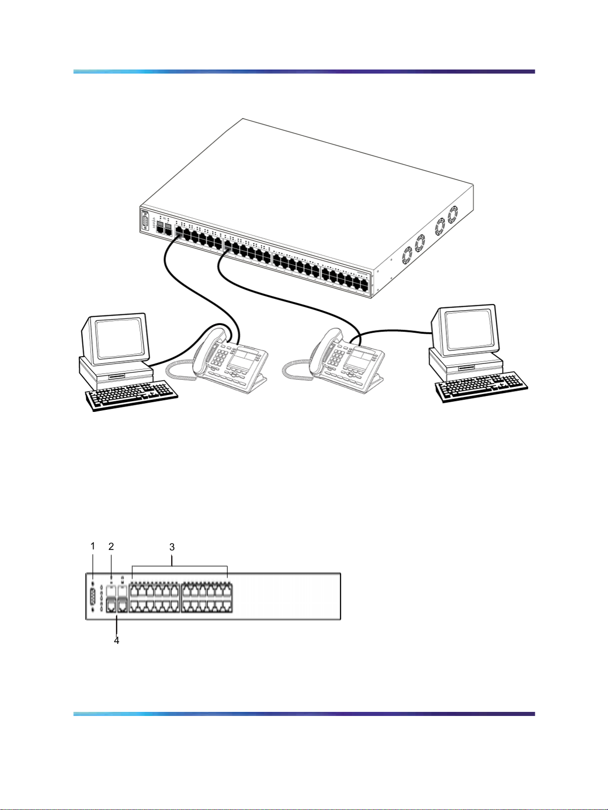
Figure 1 "Ethernet Routing Switch 2550T-PWR" (page 24) shows an
Ethernet Routing Switch 2550T-PWR providing power and Ethernet
connections to IP Phones, and data connections to personal computers
(PC).
Nortel Ethernet Routing Switch 2500 Series
Overview — System Configuration
NN47215-500 (323162-B) 02.02 Standard
Copyright © 2007, Nortel Networks
.
4.1 19 November 2007
Page 24
24 Ethernet Routing Switch 2500 Series hardware
Figure 1 Ethernet Routing Switch 2550T-PWR
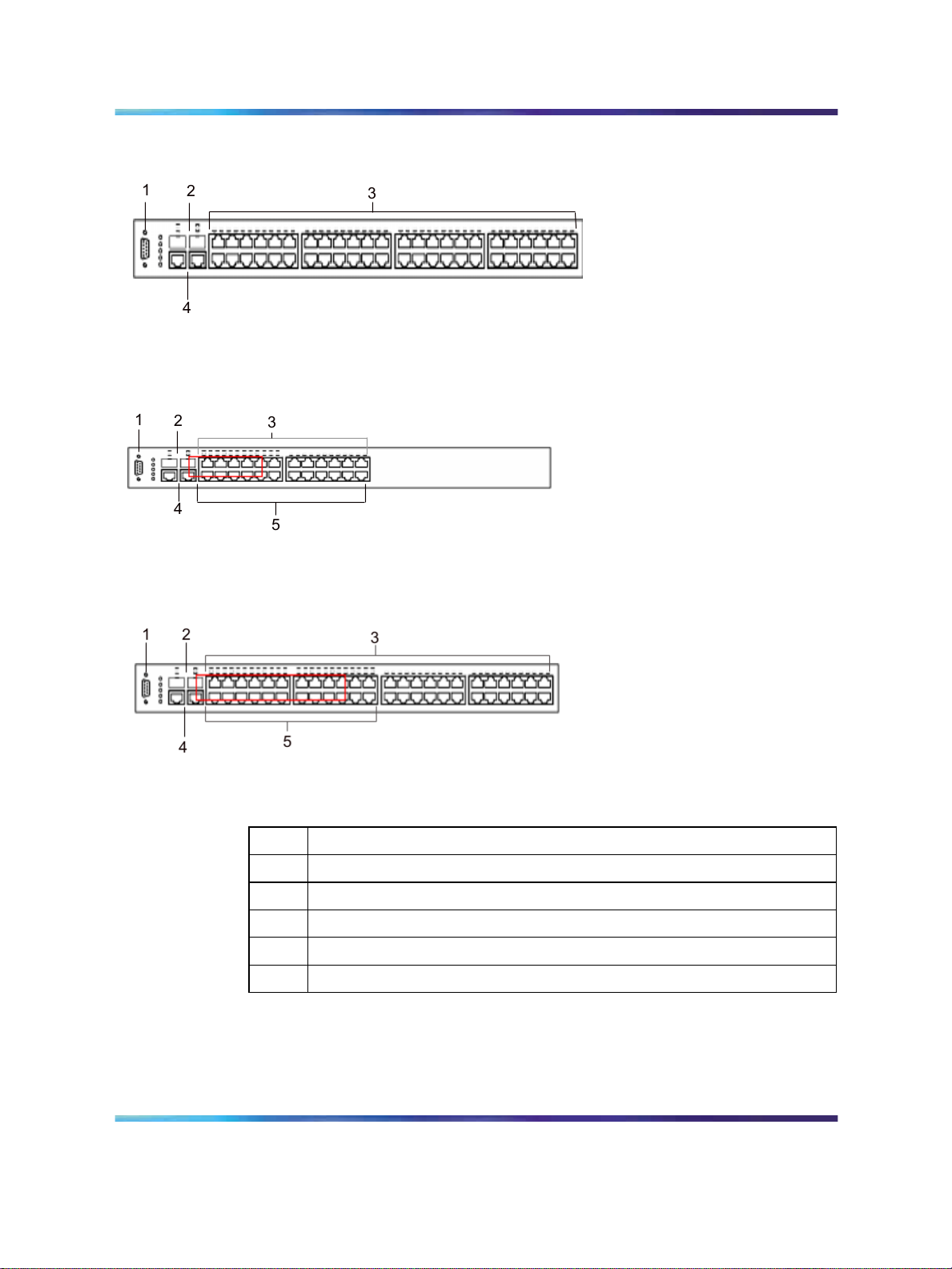
The following graphics display the front panel configuration on the Ethernet
Routing Switch 2526T, 2526T-PWR, 2550T, and 2550T-PWR. Table 1
"Components on the Ethernet Routing Switch 2500 front panel" (page
25) describes the components on the front panel.
Figure 2 Ethernet Routing Switch 2526T front panel
Nortel Ethernet Routing Switch 2500 Series
Overview — System Configuration
NN47215-500 (323162-B) 02.02 Standard
Copyright © 2007, Nortel Networks
.
4.1 19 November 2007
Page 25
Hardware components of the Ethernet Routing Switch 2500 Series 25
Figure 3 Ethernet Routing Switch 2550T front panel
Figure 4 Ethernet Routing Switch 2526T-PWR front panel
Figure 5 Ethernet Routing Switch 2550T-PWR front panel
Table 1 Components on the Ethernet Routing Switch 2500 front panel
Item Description
1
Console port
2
SFP Gigabit Interface Converter (GBIC) slots
3
10/100BaseT RJ-45 connector ports (copper)
4
10/100/1000BaseT RJ-45 connector ports (copper)
5
PoE ports (on 2526T-PWR and 2550T-PWR models only)
Console port
With the Console port, you can access the Command Line Interface (CLI)
commands to customize your network. For more information about using
the CLI, see "CLI Basics" (page 81).
Copyright © 2007, Nortel Networks
.
Nortel Ethernet Routing Switch 2500 Series
Overview — System Configuration
NN47215-500 (323162-B) 02.02 Standard
4.1 19 November 2007
Page 26

26 Ethernet Routing Switch 2500 Series hardware
The Console port is a DB-9, RS-232-D male serial port connector. You can
use this connector to connect a management station, console, or terminal to
the Ethernet Routing Switch 2500 Series by using a straight-through DB-9
to DB-9 standard serial port cable. You must use a VT100/ANSI-compatible
terminal (for cursor control and to activate cursor and functions keys) to
use the Console port.
The default settings of the Console port are:
• 9600 baud with eight data bits
•
one stop bit
•
no parity as the communications format
•
flow control set to disabled
Gigabit Interface Converter
Small Form Factor Pluggable Gigabit Interface Converters are
hot-swappable input and output enhancement components designed for
use with Nortel products to allow Gigabit Ethernet ports to link with fiber
optic networks.
SFP GBIC Support on the Ethernet Routing Switch 2500 Series
Small Form Factor Pluggable (SFP) transceivers are hot-swappable
input/output enhancement components designed for use with Nortel
products to allow Gigabit Ethernet ports to link with other Gigabit Ethernet
ports over various media types.
The Ethernet Routing Switch 2500 Series supports the following SFPs:
•
1000Base-SX SFP GBIC (mini-GBIC, connector type: LC)
•
1000Base-SX SFP GBIC (mini-GBIC, connector type: MT-RJ)
•
1000Base-LX SFP GBIC (mini-GBIC, connector type: LC)
•
CWDM SFPs
For more information about the SFP GBICs see Installing Gigabit Interface
Converters, SFPs, and CWDM SFP Gigabit Interface Converters (312865).
Port connectors
The Ethernet Routing Switch 2500 Series uses 10BASE-T/100BASE-TX
RJ-45 (8-pin modular) port connectors.
The Ethernet Routing Switch 2500 Series uses autosensing ports
designed to operate at 10 Mb/s (megabits per second) or at 100 Mb/s,
depending on the connecting device. These ports support the IEEE 802.3u
autonegotiation standard, which means that when a port is connected
to another device that also supports the IEEE 802.3u standard, the two
devices negotiate the best speed and duplex mode.
Copyright © 2007, Nortel Networks
.
Nortel Ethernet Routing Switch 2500 Series
Overview — System Configuration
NN47215-500 (323162-B) 02.02 Standard
4.1 19 November 2007
Page 27

Hardware components of the Ethernet Routing Switch 2500 Series 27
The 10BASE-T/100BASE-TX switch ports also support half- and full-duplex
mode operation.
The 10BASE-T/100BASE-TX RJ-45 switch ports can connect to 10 Mb/s or
100 Mb/s Ethernet segments or nodes.
ATTENTION
Use only Category 5 copper Unshielded Twisted Pair (UTP) cable connections
when connecting 10BASE-T/100BASE-TX ports.
Auto-MDI/MDI-X
The 10/100BASE-TX port connectors support auto-MDI/MDI-X.
Typical MDI-X ports connect over straight-through cables to the Network
Interface Card (NIC) in a node or server, similar to a conventional Ethernet
repeater hub. However, with the auto-MDI/MDI-X feature, you can still use
straight-through cables while connecting to an Ethernet hub or switch.
The auto-MDI/MDI-X feature is dependent on the autonegotiation feature.
If autonegotiation is enabled on a port, the auto-MDI/MDI-X feature is
automatically enabled on the port as well. If autonegotiation is disabled on a
port, then the port operates as a standard MDI-X port.
Power over Ethernet on Ethernet Routing Switch 2526T-PWR
and 2550T-PWR
The Ethernet Routing Switch 2526T-PWR and 2550T-PWR provide IEEE
802.3af-compliant power over the PoE-labeled front-panel RJ-45 ports. The
switches provide power discovery and power management on each port
basis. You can use the PoE ports to provide power to network appliances,
such as IP Phones, wireless access points, and video devices.
You can enable or disable power to individual ports. For information about
configuring PoE, see "Power over Ethernet for the Ethernet Routing Switch
2526T-PWR and 2550T-PWR" (page 157).
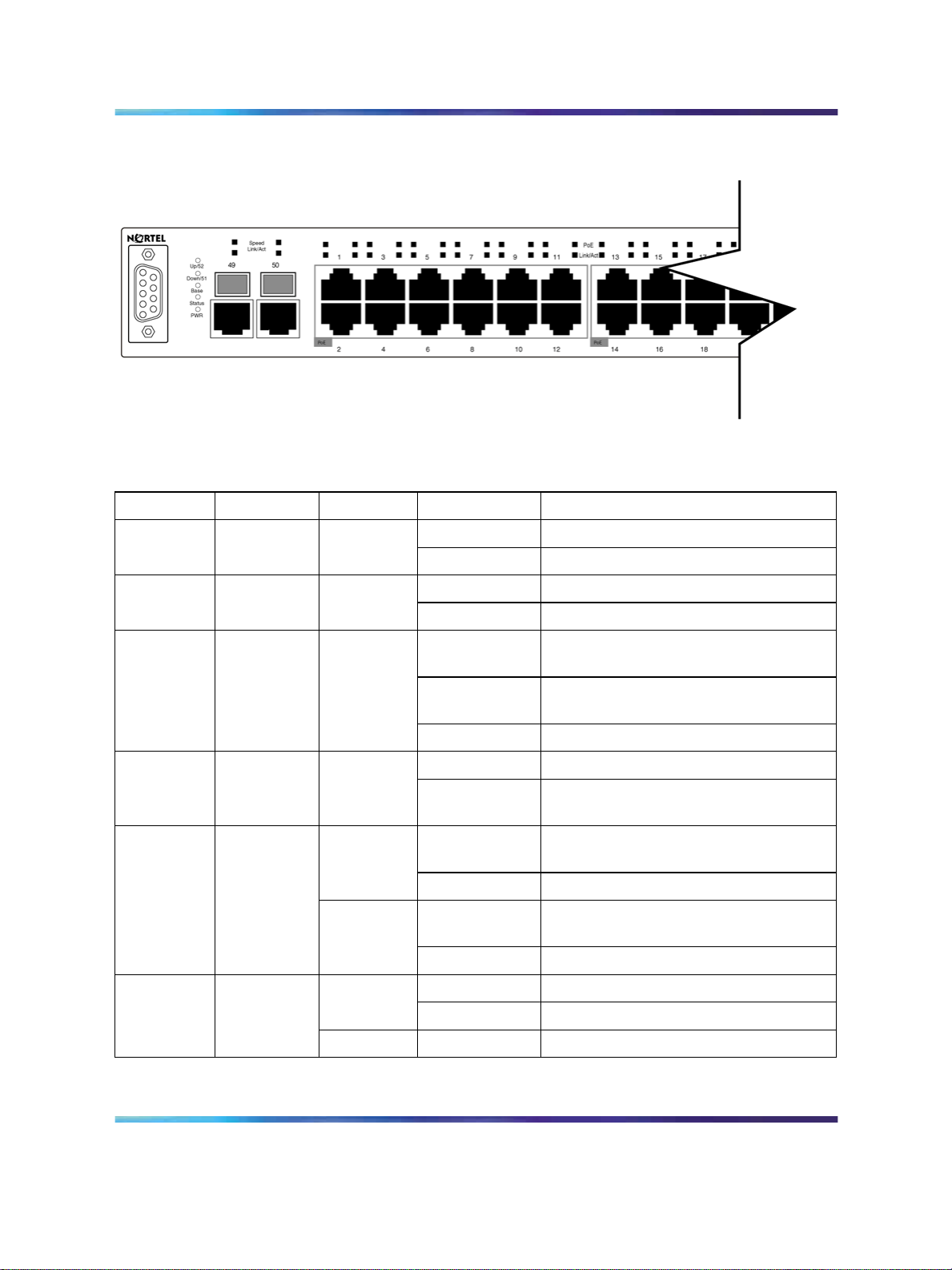
LED display panel
Figure 6 "LED display panel" (page 28) shows the LED display panel of the
Ethernet Routing Switch 2500 Series. See Table 2 "Ethernet Routing Switch
2500 Series LED descriptions" (page 28) for a description of the LEDs.
Copyright © 2007, Nortel Networks
.
Nortel Ethernet Routing Switch 2500 Series
Overview — System Configuration
NN47215-500 (323162-B) 02.02 Standard
4.1 19 November 2007
Page 28
28 Ethernet Routing Switch 2500 Series hardware
Figure 6 LED display panel
Table 2 Ethernet Routing Switch 2500 Series LED descriptions
Label Type
Rear port
Up/52
status
Rear port
Down/51
status
Status Switch
status
er Status
Speed RJ45/SFP
Uplink port
speed
Color State
Green
Fast Flashing Link is good and active.Up/28 or
Slow Flashing This port is disabled by software.
Green
Fast Flashing Link is good and active.Down/27
Slow Flashing This port is disabled by software.
Green
Flashing The switch is booting up and performing
On Self-test passed successfully and
Off The switch failed the self-test.
Green
On Power is present.PWR Switch Pow
Off Switch is not connected to a power
Green
Steady This port is set to operate at 1 Gb/s,
Flashing This port is disabled by software.
Amber
Steady This port is set to operate at 10/100
Flashing This port is disabled by software.
Meaning
a self-test.
switch is operational.
source.
and the link is good.
Mb/s, and the link is good.
Link/Act RJ45/SFP
Uplink port
status
Copyright © 2007, Nortel Networks
.
Green
Steady Link is OK.
Flashing Traffic activity.
Off No link/No traffic.
Nortel Ethernet Routing Switch 2500 Series
Overview — System Configuration
NN47215-500 (323162-B) 02.02 Standard
4.1 19 November 2007
Page 29
Hardware components of the Ethernet Routing Switch 2500 Series 29
Label Type
Link/Act Port conne
ction status
PoE port
s to PWR
models
only)
Base Base unit
power
status
status for
stack mode
Color State
Steady Station connected at 10/100 Mb/s.Green
Flashing Traffic activity at 10/100 Mb/s.
Off No link/No traffic.
Green Steady Power is supplied to the port.PoE (applie
Off No power is supplied to the port.
Green ON This unit is permanent base in stack
Amber ON This unit is selected as temporary base
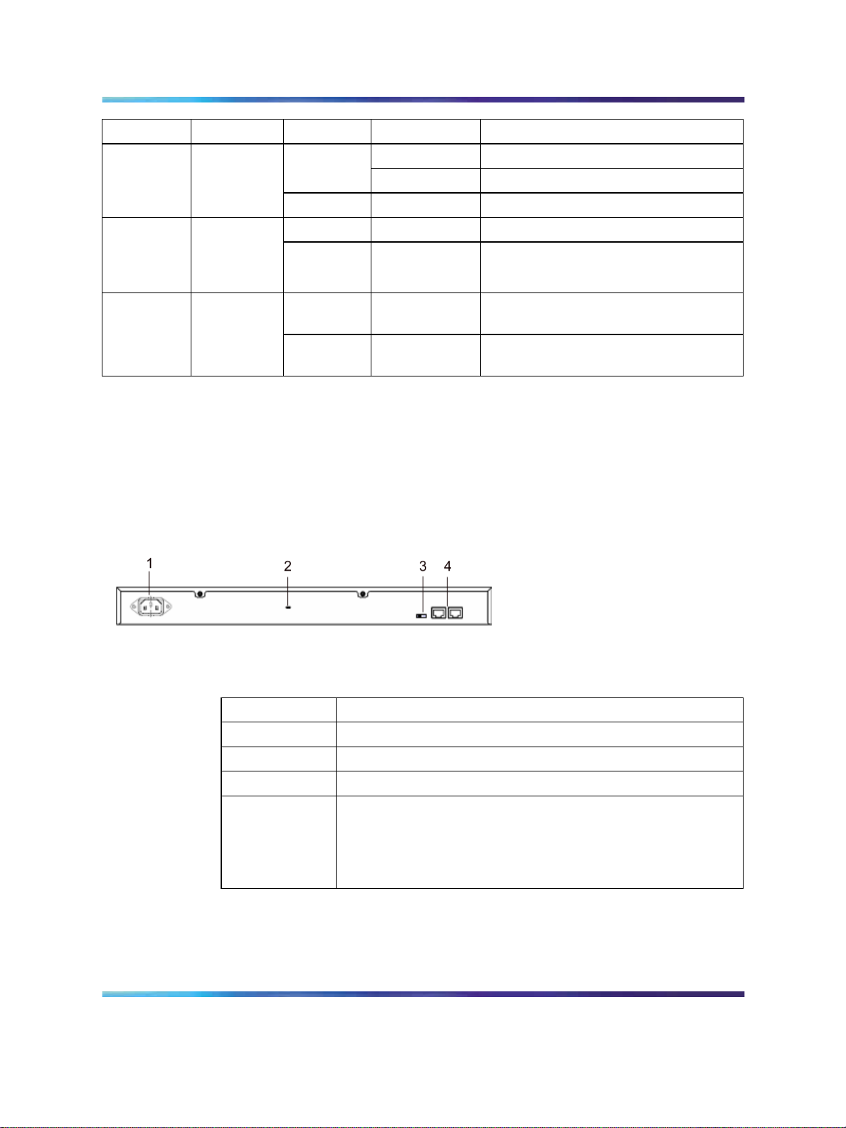
Back panel
The back panel of the Ethernet Routing Switch 2500 Series is shown in
Figure 7 " Ethernet Routing Switch 2500 Series back panel" (page 29).
Table 3 "Components on the Ethernet Routing Switch 2500 Series back
panel" (page 29) describes the components on the back panel.
Figure 7 Ethernet Routing Switch 2500 Series back panel
Meaning
mode.
in stack mode.
Table 3 Components on the Ethernet Routing Switch 2500 Series back panel
Item Description
1
2
3
4
Kensington lock
Using the Kensington lock, you can secure your switch. Wrap the steel cable
around a secure immovable object, insert the cable lock in the Kensington
Security Lock, and turn the key.
Copyright © 2007, Nortel Networks
.
AC power receptacle
Kensington lock
Base Unit select switch
Additional 1000BaseT RJ-45 connector rear ports.
For switch operating mode: ports 27,28 on 2526T models and
ports 51,52 on 2550T models.
For stack operating mode: Link UP, Link DOWN for connecting
with other units in stack.
Nortel Ethernet Routing Switch 2500 Series
Overview — System Configuration
NN47215-500 (323162-B) 02.02 Standard
4.1 19 November 2007
Page 30
30 Ethernet Routing Switch 2500 Series hardware
Cooling fans
Cooling fans are located on one side of the Ethernet Routing Switch 2500
Series to provide cooling for the internal components. When you install
the switch, be sure to allow enough space on both sides of the switch for
adequate ventilation.
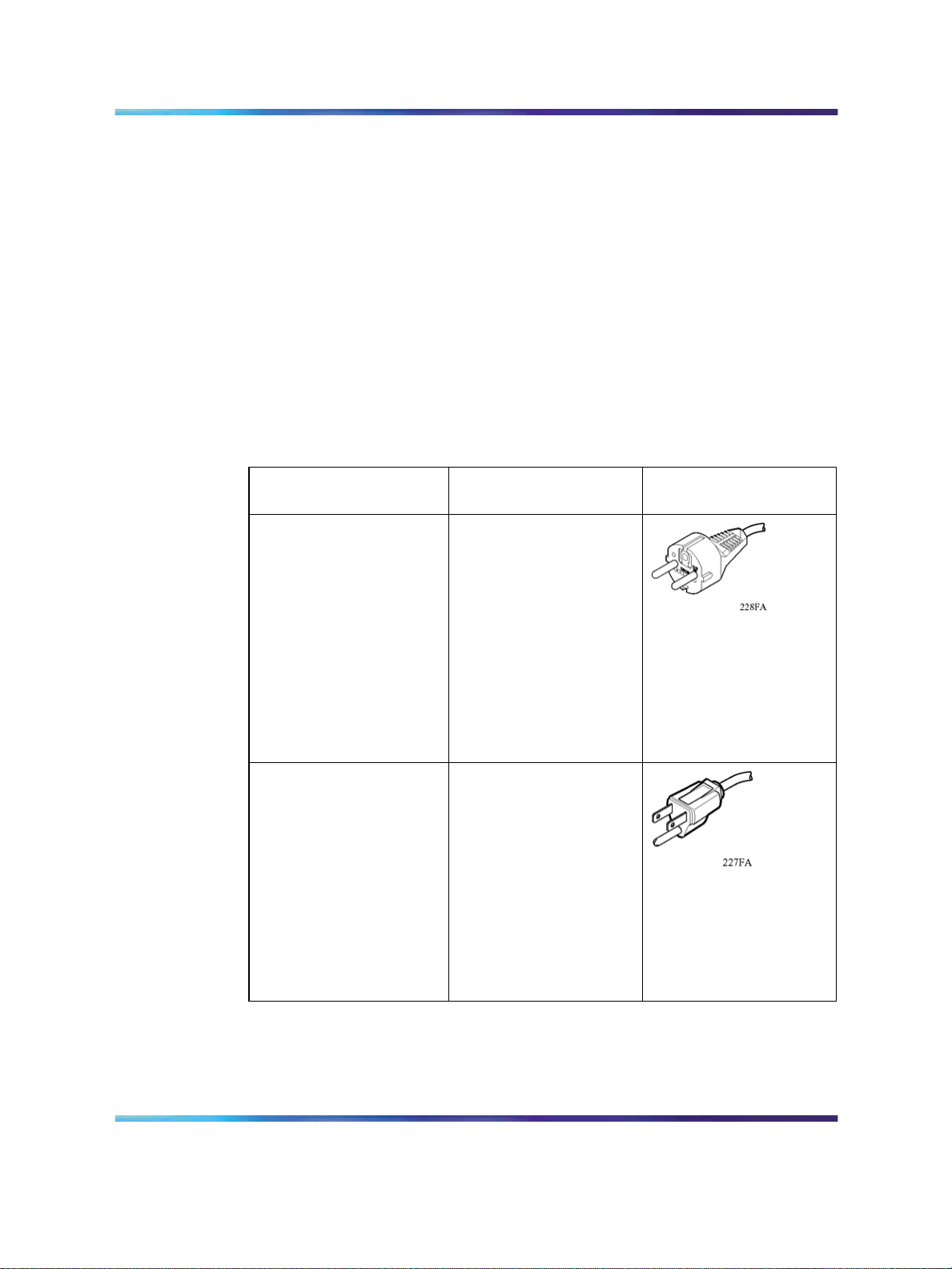
AC power receptacle
The AC power receptacle accepts the AC power cord that is supplied with
the switch. For installation outside North America, make sure that you
have the proper power cord for your region. Any cord used must have a
CEE-22 standard V female connector on one end and must meet the IEC
320-030 specifications.Table 4 "International power cord specifications"
(page 30) lists specifications for international power cords.
Table 4
International power cord specifications
Country/Plug
description
Continental Europe:
•
CEE7 standard VII
male plug
•
Harmonized cord
(HAR marking on
the outside of the
cord jacket to comply
with the CENELEC
Harmonized
Document HD-21)
U.S./Canada/Japan:
•
NEMA5-15P male
plug
•
UL recognized (UL
stamped on cord
jacket)
Specifications
220 or 230 VAC 50 Hz
Single phase
100 or 120 VAC 50– 60
Hz Single phase
Typical plug
•
CSA certified (CSA
label secured to the
cord)
Copyright © 2007, Nortel Networks
.
Nortel Ethernet Routing Switch 2500 Series
Overview — System Configuration
NN47215-500 (323162-B) 02.02 Standard
4.1 19 November 2007
Page 31

Hardware components of the Ethernet Routing Switch 2500 Series 31
Country/Plug
description
United Kingdom:
•
BS1363 male plug
with fuse
•
Harmonized cord
Australia:
AS3112-1981 Male plug
CAUTION
Read immediately.
Inspect the power cord and determine if it provides the proper
plug and is appropriately certified for use with your electrical
system. Immediately discard this power cord if it is inappropriate
for electrical systems in your country and obtain the proper cord
as required by your national electrical codes or ordinances.
Specifications
240 VAC
50 Hz
Single phase
240 VAC
50 Hz
Single phase
Typical plug
Copyright © 2007, Nortel Networks
.
See the technical documentation for this product for detailed
installation procedures to be followed by qualified service
personnel.
CAUTION
Vorsicht:
Bitte sofort lesen.
Sehen Sie nach, ob dieses Netzkabel über den richtigen
Stecker verfügt und für die Verwendung in Ihrem
Stromversogungsnetz zertifiziert ist. Falls dieses Kabel nicht für
das Stromversorgungsnetz in Ihrem Land geeignet ist, darf es
nicht verwendet werden. Besorgen Sie sich ein Kabel, das die
Vorschriften der Zulassungsbehörden in Ihrem Land erfüllt.
Die technische Dokumentation dieses Produkts enthält
ausführliche Installationsanweisungen, die nur von qualifiziertem
Kundendienstpersonal ausgeführt werden dürfen.
Nortel Ethernet Routing Switch 2500 Series
Overview — System Configuration
NN47215-500 (323162-B) 02.02 Standard
4.1 19 November 2007
Page 32

32 Ethernet Routing Switch 2500 Series hardware
Attention:
Lisez ceci immédiatement.
Examinez ce cordon d’alimentation pour déterminer s’il dispose de la fiche
appropriée et s’il est bien agréé pour utilisation sur votre installation électrique.
Débarrassez-vous en immédiatement s’il ne convient pas à l’utilisation sur
le secteur électrique en usage dans votre pays et procurez-vous un cordon
conforme à la réglementation nationale en vigueur.
Reportez-vous à la documentation technique de ce produit pour obtenir des
instructions détaillées d’installation, destinées à un technicien qualifié.
CAUTION
Attenzione:
Leggere attentamente.
Controllare questo cavo di alimentazione, verificarne il
collegamento con la presa appropriata nonché la certificazione
per l’uso nell’impianto elettrico posseduto. Non utilizzare
assolutamente in caso tale cavo non sia adatto al sistema elettrico
del paese in cui viene utilizzato e richiederne un altro certificato
dall’ente nazionale di fornitura elettrica.
ATTENTION
Per le procedure di installazione che devono essere seguite dal
personale di servizio, consultare questa documentazione tecnica
del prodotto.
CAUTION
Advertencia:
Sírvase leer inmediatamente.
Inspeccione este cable de alimentación eléctrica y determine si
viene con el enchufe apropiado y está debidamente certificado
para el uso con su sistema eléctrico. Si no cumple con los
reglamentos del sistema eléctrico de su país, despójese de
este cable de alimentación inmediatamente y obtenga el cable
requerido, según las ordenanzas y códigos eléctricos nacionales.
Refiérase a la documentación técnica de este producto para
recibir información detallada sobre los procedimientos que el
personal calificado de reparaciones deberá seguir.
Copyright © 2007, Nortel Networks
.
Nortel Ethernet Routing Switch 2500 Series
Overview — System Configuration
NN47215-500 (323162-B) 02.02 Standard
4.1 19 November 2007
Page 33

Hardware components of the Ethernet Routing Switch 2500 Series 33
WARNING
Removal of the power cord is the only way to turn off power to this
device. The power cord must always be connected in a location
that can be accessed quickly and safely in case of an emergency.
WARNING
Vorsicht:
Die Stromzufuhr zu diesem Gerät kann nur durch Ziehen des
Netzstromkabels unterbrochen werden. Die Netzsteckdose, an
die das Netzstromkabel angeschlossen ist, muß sich stets an
einem Ort befinden, der bei einem Notfall schnell und einfach
zugänglich ist.
Copyright © 2007, Nortel Networks
.
WARNING
Avertissement:
Le débranchement du cordon d’alimentation constitue le
seul moyen de mettre cet appareil hors tension. Le cordon
d’alimentation doit donc toujours être branché dans une prise
accessible pour faciliter la mise hors tension en cas d’urgence.
WARNING
Advertencia:
La única forma de desconectar la alimentación de este dispositivo
es desenchufar el cable de alimentación. El cable de alimentación
siempre debe estar conectado en una ubicación que permita
acceder al cable de forma rápida y segura en caso de emergencia.
Nortel Ethernet Routing Switch 2500 Series
Overview — System Configuration
NN47215-500 (323162-B) 02.02 Standard
4.1 19 November 2007
Page 34

34 Ethernet Routing Switch 2500 Series hardware
WARNING
Avvertenza:
Estrarre il cavo di alimentazione è l’unico sistema per spegnere il
dispositivo. Il cavo di alimentazione deve essere sempre collegato
in una posizione che permetta l’accesso facile e sicuro in caso
di emergenza.
Network configuration examples
This section provides network configuration examples using the Ethernet
Routing Switch 2500 Series switches. In these examples, traffic Quality of
service (QoS) feature can be used to prioritize the traffic of the network to
ensure uninterrupted traffic of critical applications. The examples are:
•
"Small office desktop switch application" (page 34)
•
"Branch office workgroup switch application" (page 35)
•
"Medium sized office wiring closet switch application" (page 36)
Small office desktop switch application
Figure 8 "Ethernet Routing Switch 2500 Series used as a desktop switch"
(page 35) shows the Ethernet Routing Switch 2500 Series used as a
desktop switch in a small office environment. The desktop workstations and
servers are connected directly to the switch ports. Alternatively, an ERS
2500 series switch that supports Power over Ethernet (PoE) can provide
connectivity and power to Wireless LAN Access Points (WLAN APs) in
addition to desktop workstations and servers.
Copyright © 2007, Nortel Networks
.
Nortel Ethernet Routing Switch 2500 Series
Overview — System Configuration
NN47215-500 (323162-B) 02.02 Standard
4.1 19 November 2007
Page 35

Network configuration examples 35
Figure 8 Ethernet Routing Switch 2500 Series used as a desktop switch
Branch office workgroup switch application
Figure 9 "Ethernet Routing Switch 2500 Series used as a workgroup
switch" (page 36) shows the Ethernet Routing Switch 2500 Series used as
a workgroup switch in an enterprise branch office environment. Desktop
workstations and servers are connected directly to the switch ports.
Alternatively, an ERS 2500 series switch that supports Power over Ethernet
(PoE) can provide connectivity and power to IP Phones and Wireless LAN
Access Points (WLAN APs) in addition to desktop workstations and servers.
The Ethernet Routing Switch 2500 series switch can optionally be stacked
up to 8 units to form a single virtual switch providing up to 384 10/100Mb/s
connections and 16 1000Mb/s connections.
Copyright © 2007, Nortel Networks
.
Nortel Ethernet Routing Switch 2500 Series
Overview — System Configuration
NN47215-500 (323162-B) 02.02 Standard
4.1 19 November 2007
Page 36

36 Ethernet Routing Switch 2500 Series hardware
Figure 9 Ethernet Routing Switch 2500 Series used as a workgroup switch
Medium sized office wiring closet switch application
Figure 10 "Configuring power workgroups and a wiring closet switch" (page
37) shows the Ethernet Routing Switch 2500 series used as a wiring
closet switch in a medium to large enterprise office environment. Desktop
workstations, IP Phones, and WLAN APs are connected directly to the
switch ports.
Figure 10 "Configuring power workgroups and a wiring closet switch"
(page 37) shows the Ethernet Routing Switch 1600 series used as a
backbone switch, connecting to Ethernet Routing Switch 2500 – S1, with
an optional 1000BASE-SX SFP GBIC for maximum bandwidth. S2 is a
single virtual switch stack of three ERS 2500 switches providing 10 or
100Mb/s, also connecting to the ERS 1624G backbone switch with an
optional 1000BASE-SX SFP GBIC in both switches.
Copyright © 2007, Nortel Networks
.
Nortel Ethernet Routing Switch 2500 Series
Overview — System Configuration
NN47215-500 (323162-B) 02.02 Standard
4.1 19 November 2007
Page 37

Network configuration examples 37
Figure 10
Configuring power workgroups and a wiring closet switch
Copyright © 2007, Nortel Networks
.
Nortel Ethernet Routing Switch 2500 Series
Overview — System Configuration
NN47215-500 (323162-B) 02.02 Standard
4.1 19 November 2007
Page 38

38 Ethernet Routing Switch 2500 Series hardware
Copyright © 2007, Nortel Networks
.
Nortel Ethernet Routing Switch 2500 Series
Overview — System Configuration
NN47215-500 (323162-B) 02.02 Standard
4.1 19 November 2007
Page 39

Nortel Ethernet Routing Switch 2500 Series stacking
This chapter includes information about the stacking features, such as stack
capabilities, stacking functionality delivery,stack configuration, and Auto Unit
Replacement. This chapter contains information about the following topics:
•
"Stacking capabilities" (page 39)
•
"Stacking functionality delivery" (page 40)
•
"Stack configuration" (page 45)
•
"Auto Unit Replacement" (page 54)
Stacking capabilities
The Nortel Ethernet Routing Switch 2500 Series contain two built-in rear
ports that can be used as stacking/cascade ports to enable a stack of up to
eight units.
39
A stack can consist of Nortel Ethernet Routing Switch 2526T, Nortel Ethernet
Routing Switch 2550T, Nortel Ethernet Routing Switch 2526T-PWR, and
Nortel Ethernet Routing Switch 2550T-PWR units.
The stack ports on ERS 2500 series switches provide 4Gbps (FDX) stack
bandwidth for an aggregate of up to 32Gbps for a stack of eight units.
A stack of Ethernet Routing Switch 2500 series switches can also consist of
a mix of stack pre-enabled units as well as non pre-enabled units. The non
pre-enabled units in a stack must meet the following requirements before
they are added into a stack configuration:
•
contain a valid license file (a license file contains the switch MAC
addresses)
•
Operational mode of rear ports operating in Stacking Mode
Copyright © 2007, Nortel Networks
.
Nortel Ethernet Routing Switch 2500 Series
Overview — System Configuration
NN47215-500 (323162-B) 02.02 Standard
4.1 19 November 2007
Page 40

40 Nortel Ethernet Routing Switch 2500 Series stacking
Stacking functionality delivery
The Nortel Ethernet Routing Switch 2500 series switches allow you to
stack multiple switches together to create a single virtual switch that can
be managed as a single device. Stacking functionality is delivered in
two distinctively different ways on Ethernet Routing Switch 2500 series
switches:
•
Through stack enabled units with order codes AL2515xxx-E6. The
rear ports of stack enabled ERS 2500 switch are factory pre-enabled,
configured, and operating in Stacking Mode by default and are ready
to stack. These units do not require or use the software licensing
mechanism.
•
Through software using a licensing mechanism for standalone units with
order codes AL2500xxx-E6. Standalone ERS 2500 switches require the
purchase of a Stacking License Kit for each license to create a license
file, which unlocks stacking capability on standalone units.
Stack enabled switches
The stack enabled unit rear ports are configured in Stacking Mode at
the factory and are ready for immediate use for connection in a stack
configuration. Stacking Mode is the default operating mode that cannot be
overridden by a factory default. Standalone Mode operation is still available
for configuration on the rear-ports of stack enabled units. For information
on adding or replacing a new unit, see "Adding/Replacing a stack unit"
(page 53).
All factory pre-enabled units are identifiable through CLI, Web UI, and
Device Manager with the text Stack Enabled included in the switch
description for identification purposes.
Standalone configuration with license files
Standalone units are not pre-enabled with stacking capability in the factory
and require the use of a software based licensing mechanism to unlock
stacking functionality for activation on the rear ports. Standalone units use
the GenLic engine for decryption of a license file. The license file must
contain the switch MAC address to unlock the stacking functionality.
Standalone units require the purchase of an Ethernet Routing Switch 2500
series Stacking License Kit, of which there are four types available. Each kit
contains a License Certificate with a License Authorization Code (LAC) that
enables a specific number of stacking licenses for one or multiple ERS 2500
series switches. Each ERS 2500 series switch requires one license file to
unlock stacking functionality. A single license file can contain up to 1000
switch MAC addresses for installation on multiple switches.
Copyright © 2007, Nortel Networks
.
Nortel Ethernet Routing Switch 2500 Series
Overview — System Configuration
NN47215-500 (323162-B) 02.02 Standard
4.1 19 November 2007
Page 41

Stacking functionality delivery 41
A Stacking License Certificate contains instructions on how to deposit
license entitlements into a license bank, enter switch MAC address(es),
create the license file, then download and copy the license file onto each
switch requiring stacking functionality. These instructions are carried out on
the Nortel Licensing portal web site at: w
ww.nortellicensing.com.
ATTENTION
Once a valid license file is downloaded on to an Nortel Ethernet Routing Switch
2500 Series switch, you can configure the operational mode of rear ports to
Stacking Mode. Although the rear ports are set to Stacking Mode, a reboot of the
switch is required to fully enable the stacking operation.
Working with license files using the CLI
With the following commands, you can copy the license file to your switch
and display or clear the existing license information:
•
"copy tftp license command" (page 41)
•
"show license command" (page 42)
•
"clear license command" (page 42)
copy tftp license command The copy tftp license command
copies the license file from a TFTP server to your switch. After you copy the
license to the switch, you need to perform a reboot to activate the license.
The license is copied to NVRAM. If you reset the switch to default, this removes
the license from the switch. But the stacking feature is enabled until you configure
the switch to Standalone Mode.
The syntax for the copy tftp license command is:
copy tftp license <A.B.C.D> <WORD>
The copy tftp license command is executed in the Privileged EXEC
command mode.
"copy tftp license command parameters" (page 41) describes the
parameters and variables for the copy tftp license command.
copy tftp license command parameters
Parameters and
variables
Description
ATTENTION
<A.B.C.D> The TFTP server address.
<WORD> The software license filename on the TFTP server.
Nortel Ethernet Routing Switch 2500 Series
Overview — System Configuration
NN47215-500 (323162-B) 02.02 Standard
Copyright © 2007, Nortel Networks
.
4.1 19 November 2007
Page 42

42 Nortel Ethernet Routing Switch 2500 Series stacking
show license command The show license command displays the
existing licenses on your switch. The syntax for the show license
command is:
show license { <1-10> | all }
The show license command is executed in the Privileged EXEC
command mode.
Table 5 show license command parameters
Parameters and variables Description
<1-10>
all Displays all licenses.
Displays the selected licenses.
The following figure displays a sample output for the show license all
command after installing the license file.
Figure 11 show license all command output
clear license command The clear license command deletes the
existing licenses on your switch.
The syntax for the clear license command is:
clear license { <1-10> | all }
The clear license command is executed in the Privileged EXEC
command mode.
Copying the license file using the Java Device Manager
Use the Java Device Manager to copy the license file to the 2500 Series
Nortel Ethernet Routing Switch.
Copyright © 2007, Nortel Networks
.
Nortel Ethernet Routing Switch 2500 Series
Overview — System Configuration
NN47215-500 (323162-B) 02.02 Standard
4.1 19 November 2007
Page 43

Step Action
Stacking functionality delivery 43
1
From the Device Manager menu select Edit > File System.
The FileSystem dialog box appears.
2
Click the License File tab.
The License File tab appears.
3
In the LoadServerAddr field, enter the TFTP server address.
4 In the LicenseFileName field, enter the software license filename
on the TFTP server.
ATTENTION
The LicenseFileName field is case sensitive and you can use a maximum
of 64 characters including the file extension. Numerals are allowed in the
LicenseFileName but special characters like @, -, #, and so on are not allowed.
5
6
7
8
9
In the LicenseFileAction field, select dnldLicense.
Click Apply.
Click Refresh.
The LicenseFileStatus field displays the file copy progress. After
the file copy completes, a warning message appears prompting you
to reboot the switch and activate the license.
To reboot the switch, choose Edit > Chassis
Under the System tab, select the reboot option and click Apply.
—End—
Copyright © 2007, Nortel Networks
.
Nortel Ethernet Routing Switch 2500 Series
Overview — System Configuration
NN47215-500 (323162-B) 02.02 Standard
4.1 19 November 2007
Page 44

44 Nortel Ethernet Routing Switch 2500 Series stacking
Downloading the license files using the Web-based management
interface
You can download the license files to the Nortel Ethernet Routing Switch. To
download the Ethernet Routing Switch 2500 Series license files, a properly
configured Trivial File Transfer Protocol (TFTP) server must be present in
your network, and the Ethernet Routing Switch 2500 Series must have an
IP address.
To download a license file, use the following procedure:
Step Action
1
From the main menu, choose Configuration > License Download.
The License Download page appears.
Figure 12 License Download page
The following table describes the fields on the License Download
page.
Table 6
License Download page fields
Fields Description
License Image Filename Type the valid license image filename.
Select Target Choose the target address.
TFTP Server IP Address Type the IP address of your TFTP download
host.
Start Load of New License File ChooseYes to start downloading the new license
file immediately and No to cancel.
Remove License File Number Choose the license number to be removed.
2
3
Copyright © 2007, Nortel Networks
.
Type information in the text boxes, or select from a list.
Click Submit.
Nortel Ethernet Routing Switch 2500 Series
Overview — System Configuration
NN47215-500 (323162-B) 02.02 Standard
4.1 19 November 2007
Page 45

Stack configuration
The Nortel Ethernet Routing Switch 2500 series provides the capability for
intelligent fail-safe resilient stacking of up to eight units in a single switch
stack. This provides uninterrupted connectivity of up to 400 user ports in a
virtual switch managed as a single unit.
All ERS 2500 series switches must be running software release 4.1 before being
connected in a stack configuration.
To set up a stack, do the following:
Step Action
1 Power down all switches.
Stack configuration 45
—End—
ATTENTION
2
Set the Unit Select switch at the rear of the non-base units to the
off position.
3
Plug all stack cables in to the rear RJ-45 cascade ports and ensure
the cables are connected from Cascade Down on the first unit to
Cascade Up on the second unit and so on. The last unit in the stack
must be connected back to the first unit for full stack resiliency.
Ensure all the cascade cables are properly connected.
4
Power up all the switches in the stack starting with the Base unit.
ATTENTION
In a mixed stack of 2526T, 2526T-PWR, 2550T, and 2550T-PWR, any
switch can act as the Base unit.
—End—
ATTENTION
The rear ports must be operating Stacking Mode before adding a switch into
a stack.
Copyright © 2007, Nortel Networks
.
Nortel Ethernet Routing Switch 2500 Series
Overview — System Configuration
NN47215-500 (323162-B) 02.02 Standard
4.1 19 November 2007
Page 46

46 Nortel Ethernet Routing Switch 2500 Series stacking
Configuring the operational mode on rear ports using the CLI
You can use the following commands to configure the operational mode of
rear ports into Stacking or Standalone Mode:
•
"rear-ports mode command" (page 46)
•
"show rear-ports mode command" (page 46)
rear-ports mode command
The rear-ports mode command configures the operational mode of
the rear-port.
The syntax for the rear-ports mode is:
# rear-ports mode [unit <1-8>] {standalone|stacking}
The rear-ports mode command is executed in the Global Configuration
command mode.
Table 7 "rear-ports mode command" (page 46) describes the parameters
and variables for the rear-ports mode command.
Table 7 rear-ports mode command
Parameters and variables Description
[unit <1-8>]
{standalone|stacking}
Specifies the unit number. You can use a
maximum of eight units.
Specifies the operational mode of the selected
unit.
show rear-ports mode command
The show rear-ports mode displays the operational mode of the rear
port.
The syntax for the show rear-ports mode is:
# show rear-ports mode
The show rear-ports mode command is executed in Global
Configuration command mode in the CLI. There are no parameters and
variables for show rear-ports mode command.
Figure 13 "show rear-ports mode command output" (page 47) displays a
sample output of the show rear-ports mode command when the rear
ports are set and running in Stacking Mode.
Copyright © 2007, Nortel Networks
.
Nortel Ethernet Routing Switch 2500 Series
Overview — System Configuration
NN47215-500 (323162-B) 02.02 Standard
4.1 19 November 2007
Page 47

Stack configuration 47
Figure 13 show rear-ports mode command output
Configuring the operational mode of rear ports using the Device
Manager
Use the Device Manager to configure the operational mode of the rear ports
into Standalone or Stacking Mode in the Ethernet Routing Switch 2500
Series. For more information on configuring the operational mode of rear
ports, see "Rear Ports Mode tab" (page 252)
Rear ports and stacking
The rear panel view of a Nortel Ethernet Routing Switch 2500 series
switch consists of two RJ-45 1000BaseT ports and a Unit Select switch. In
Stacking Mode, the two rear ports become the Cascade Down and Cascade
Up ports for connecting switch units in a stack configuration. The rear panel
components are illustrated in the following diagram:
Figure 14 Rear panel components
Unit Select switch
The Unit Select switch is used to designate a switch in the stack as the
base unit. Sliding the switch to the right designates that switch as the base
unit. Only one switch in a stack has the Unit Select switch in the base unit
position. All other switches in the stack must have the Unit Select switch in
the left position.
The base unit designation of a switch is also displayed on the front panel
LED display. For more information, see Table 2 "Ethernet Routing Switch
2500 Series LED descriptions" (page 28)
Copyright © 2007, Nortel Networks
.
Nortel Ethernet Routing Switch 2500 Series
Overview — System Configuration
NN47215-500 (323162-B) 02.02 Standard
4.1 19 November 2007
Page 48

48 Nortel Ethernet Routing Switch 2500 Series stacking
Cascade Down port
The Cascade Down port is used to connect this switch unit to the next unit
in the stack through a stack cable. A connection from this port must be
attached to the Cascade Up port of the next switch in the stack. A return
cable from the Cascade Down port of the last unit must be connected to
the Cascade Up port of the first unit to complete the stack connection.
ATTENTION
Each Nortel Ethernet Routing Switch 2500 series switch is supplied with one
46-cm stack cable to create a stack connection. For stacking three or more units
(maximum 8 units per stack), you need to order the 1.5 or 3 meters stack return
cable (order number AL2518002-E6 and AL2518003-E6, respectively).
Cascade Up port
The Cascade Up port is used to accept a stack cable connection from
an adjacent unit above. A return cable from the Cascade Up port of the
first unit must be connected to the Cascade Down port of the last unit to
complete a stack connection.
ATTENTION
Nortel Ethernet Routing Switch 2500 series switches use tested and certified
Category 5E UTP cables as stack cables. All Nortel branded ERS 2500 series
stack cables are for use with these switches. However, Cat 5E stack cable
connections of up to 100 meters is possible between each ERS 2500 switch but
not officially supported. Using non-Nortel tested and certified stack cables for
such configurations are solely the user’s responsibility should any stack operation
issues occur.
The following illustration demonstrates the proper stack cable crossover
configuration. Failure to use this configuration can result in loss of
connectivity. This example shows a cascade down configuration
Connecting stack cables
Copyright © 2007, Nortel Networks
.
Nortel Ethernet Routing Switch 2500 Series
Overview — System Configuration
NN47215-500 (323162-B) 02.02 Standard
4.1 19 November 2007
Page 49

1. Base Unit
2. Cascade Cable
3. Cascade Cable (used for return)
Initial stack installation
During the initial installation of the stack, the software automatically
determines the physical order of all units in the stack according to the
position of the base unit within the stack. Thereafter, the individual units
maintain their original unit numbering, even if the position of one or more
units in the stack is changed.
For example, when the stack is initially powered, the base unit becomes unit
1 and the unit that the base unit connects to (via the Cascade Down cable)
becomes unit 2 (and the next unit is unit 3 and so on), until the maximum
stack configuration (up to 8 units) is reached. If the base unit is changed to
another unit in the stack, the new base unit keeps its original unit number
in the stack.
Stack MAC address
When a switch participates in a stack configuration, a stack MAC address is
automatically assigned during stack initialization. The stack MAC address is
the base unit MAC address plus 1. If another unit in the stack is assigned
as the base unit, the new stack MAC address is the MAC address of the
new base unit plus 1. The original stack IP address still applies to the new
base unit.
Stack configuration 49
Stack configurations
Due to stack parameters being associated with the base unit, the physical
stack order depends on the base unit position and whether the stack is
configured cascade up (stack up) or cascade down (stack down). This
designation depends on the stack cabling arrangement.
The system automatically numbers the physical units based on the
designated base unit (Unit 1). In a cascade down configuration, the base
unit is physically located as the top unit in the stack. The cable connected to
the Cascade Down connector of the base unit terminates in the Cascade Up
connector on the next unit in the stack which is physically located below the
base unit. This next unit is designated Unit 2. The stack is wired downward
through the units and the system continues to number in this manner
throughout the stack. In this configuration, the base unit discovers the
stack in a cascade down (stack down) direction. The following illustration
demonstrates a cascade down (stack down) configuration.
Copyright © 2007, Nortel Networks
.
Nortel Ethernet Routing Switch 2500 Series
Overview — System Configuration
NN47215-500 (323162-B) 02.02 Standard
4.1 19 November 2007
Page 50

50 Nortel Ethernet Routing Switch 2500 Series stacking
ATTENTION
Many network management software packages assume a cascade down (stack
down) configuration, Nortel recommends the usage of this configuration.
Cascade down stack configuration
In a cascade up (stack up) configuration, the base unit is physically
located as the top unit in the stack. The cable connected to the Cascade
Down connector of the base unit terminates in the Cascade Up connector
physicallylocated at the bottom of the stack. This next unit is designated Unit
2. The stack is wired upward through the units and the system continues to
number in this manner throughout the stack. In this configuration, the base
unit discovers the stack in a cascade up (stack up) direction. The following
illustration demonstrates a cascade up (stack up) configuration.
Copyright © 2007, Nortel Networks
.
Nortel Ethernet Routing Switch 2500 Series
Overview — System Configuration
NN47215-500 (323162-B) 02.02 Standard
4.1 19 November 2007
Page 51

Cascade up stack configuration
Stack configuration 51
Regardless of stack configuration, the following applies:
•
When power is applied to the stack the base unit initializes, typically
within 60 seconds, and the entire stack powers up as a single logical unit.
•
A RS-232 communications cable can be attached to the console port of
any switch in the stack to establish a console connection.
• Asoftware upgrade can be performed on the stack from any switch using
the console interface, a Telnet session, the web-based management
interface, or any SNMP-based management software.
•
The stack can be managed using a Telnet session, web-based
management interface, or any SNMP-based management software
through any stack switch port.
• When stacking two or more switches. use the 3 meters cascade
max-return cable (part number AL2518003-E6) to complete the link
from the last unit in the stack to the base unit.
Temporary base unit
If an assigned base unit fails, the next unit in the stack order automatically
becomes the new temporary base unit. This change is indicated by the
Base LED on the temporary base unit LED display panel moving to a steady
amber state.
Copyright © 2007, Nortel Networks
.
Nortel Ethernet Routing Switch 2500 Series
Overview — System Configuration
NN47215-500 (323162-B) 02.02 Standard
4.1 19 November 2007
Page 52

52 Nortel Ethernet Routing Switch 2500 Series stacking
This automatic failover is only a temporary safeguard. If the stack
configuration loses power, the temporary base unit cannot power up as
the base unit when power is restored. Also, if the original unit rejoins the
stack, it cannot resume base unit status. For this reason, always assign
the temporary base unit as the base unit until the failed unit is repaired
or replaced.
ATTENTION
If the temporary base unit is not assigned as the new base unit, and the temporary
base unit fails, the next unit in the stack order becomes the temporary base
unit. This process continues after successive failures until only two units are left
in the stack.
Redundant cascade stacking
The Nortel Ethernet Routing Switch 2500 Series allows a stack of up to 8
units into a dual-path cascade stack. If any single unit fails or if a cable is
accidently disconnected, other units in the stack remain operational without
interruption.
In addition to increasing bandwidth, the software uses the cables to provide
two paths between units. If one path breaks the data travels over the
remaining path with half the normal inter-switch bandwidth.
The following diagram shows an example of a stack configuration with a unit
failure in the stack. This illustrates:
• Unit 3 becomes non-operational due to a unit failure, cable
disconnection, or a loss of power.
•
Units 2 and 4, directly upstream and downstream from Unit 3, sense
the loss of link signals from unit 3. The software causes all the data to
traverse the remaining path.
•
The Cascade Down LED for Unit 2 and the Cascade Up LED for Unit 4
turn amber to indicate an error has been detected.
•
The remaining stack units continue to be connected.
Copyright © 2007, Nortel Networks
.
Nortel Ethernet Routing Switch 2500 Series
Overview — System Configuration
NN47215-500 (323162-B) 02.02 Standard
4.1 19 November 2007
Page 53

Redundant cascade stacking
Stack configuration 53
Removing a stack unit
If a unit is removed from the stack, the following switch configuration settings
revert to those configured before the unit became a member of the stack:
•
IP address
•
Console, Web, Telnet, and SNMP passwords
•
SNMP community strings
Adding/Replacing a stack unit
To replace a failed stack unit or insert a new unit into a stack, follow this
procedure:
Step Action
1
2
Upload a copy of the stack configuration file to a TFTP server.
Since unit failure is not a predictable situation, it is suggested that
the stack configuration file is backed up regularly to a TFTP server.
Obtain the new ERS 2500 switch.
Copyright © 2007, Nortel Networks
.
Nortel Ethernet Routing Switch 2500 Series
Overview — System Configuration
NN47215-500 (323162-B) 02.02 Standard
4.1 19 November 2007
Page 54

54 Nortel Ethernet Routing Switch 2500 Series stacking
Ensure that the new switch is set to factory default values. Then,
if the unit is a standalone ERS 2500 switch, ensure that a valid
stacking license.dat file is installed on the switch and the rear ports
are operating in Stacking Mode. If the unit is a Stack Enabled
ERS 2500 switch, then the unit is ready for adding or replacing.
For information on installing a stacking license, see "Standalone
configuration with license files" (page 40).
3
Download the configuration file to the new unit.
Manually insert the new unit in the stack. Turn off the new unit
inserted into the stack and manually replace the failed unit in the
stack. Plug in the stack cables into the appropriate cascade ports.
4
Power up the new unit in the stack.
The new unit joins the stack and the configuration of the failed unit is
replicated onto it. Once the replication is completed, the new unit
is reset and rejoins the stack automatically.
If the base unit is being replaced, remember that the stack elected a
temporary base unit. The new unit cannot automatically resume operation
as the base unit even with the Unit Select switch set to Base. To restore the
stack to its original running state with the new unit set to Base using the
Unit Select switch, the switch stack must be reset.
Auto Unit Replacement
The Auto Unit Replacement (AUR) feature enables users to replace a unit
from a stack while retaining the configuration of the unit. This feature
requires the stack power to be on during the unit replacement.
—End—
The main feature of the AUR is the ability to retain the configuration (CFG)
image of a unit in a stack during a unit replacement. The retained CFG
image from the old unit is restored to the new unit. Because retained CFG
images are kept in the DRAM of the stack, the stack power must be kept on
during the procedure.
In order for AUR to function properly, the new unit and the existing units in the
stack must all be running the same version of software (Release 4.1 software
or later).
Copyright © 2007, Nortel Networks
.
ATTENTION
Nortel Ethernet Routing Switch 2500 Series
Overview — System Configuration
NN47215-500 (323162-B) 02.02 Standard
4.1 19 November 2007
Page 55

Auto Unit Replacement 55
ATTENTION
AUR is intended for a stack configuration of two or more units. In a two-unit stack
configuration, if a unit fails, the remaining unit becomes a standalone switch. AUR
loads the configuration of the failed unit in the replacement of ERS 2500 Series
unit if the failed unit was a non-Base Unit.
AUR is not designed for the situation of removing and reinserting the same switch
(with the same MAC address).
Other information related to this feature:
•
The new unit must be the same hardware configuration as the old,
including the same number of ports.
•
If the administrator adds a new unit with a different hardware
configuration, the configuration of this unit is used.
• If the administrator adds a new unit with the same hardware
configuration, the previous configuration of the new unit is lost. It is
overwritten with the restored configuration from the stack.
•
This feature can be disabled/enabled at any time using the CLI. The
default mode is ENABLE.
•
Customer log messages are provided.
After booting a stack, use the CLI command show stack auto-unit-
replacement from a unit console to find out if that unit is ready for replacement.
AUR function
The CFG mirror image is a mirror of a CFG image (in FLASH) of a unit in
a stack. The mirror image does not reside in the same unit with the CFG
image. The unit that contains the CFG image is called the Associated Unit
(AU) of the CFG mirror image. The MAC Address of the AU is called the
Associated Mac Address (AMA) of the CFG mirror image.
An active CFG Mirror Image is a CFG mirror image that has its AU in the
stack. An INACTIVE CFG Mirror Image is a CFG mirror image for which
the associated AU has been removed from the stack. When a CFG mirror
image becomes INACTIVE, the INACTIVE CFG mirror image is copied
to another unit.
ATTENTION
The stack always keeps two copies of an INACTIVE CFG mirror image in
the stack in case one unit is removed–the other unit can still provide the
backup INACTIVE CFG mirror image.
Copyright © 2007, Nortel Networks
.
Nortel Ethernet Routing Switch 2500 Series
Overview — System Configuration
NN47215-500 (323162-B) 02.02 Standard
4.1 19 November 2007
Page 56

56 Nortel Ethernet Routing Switch 2500 Series stacking
CFG mirror image process
The CFG mirror image process is triggered by specific events.
Power Cycle After a power cycle, all the CFG images in a stack are
mirrored.
Figure 15 "CFG mirror process in stack" (page 56) illustrates the CFG mirror
images in a three-unit stack after the stack is powered on. Unit 1 is the
Based Unit (BU) and all other units are Non-Based Units (NBU).
•
Unit 1 (BU) contains mirror images for unit 2 (CFG 2) and unit 3 (CFG 3).
•
Unit 2 (NBU), is the TEMP-BU. It contains a mirror image of unit 1 (CFG
1), in case the BU (unit 1) is removed from the stack.
•
All three mirror images (CFG 1, CFG 2, and CFG 3) are active.
•
Unit 2 is the Associated Unit of the CFG 2 mirror image.
•
The Mac Address 2 is the Associated Mac Address (AMA) of the CFG
2 mirror image.
Figure 15 CFG mirror process in stack
Copyright © 2007, Nortel Networks
.
Nortel Ethernet Routing Switch 2500 Series
Overview — System Configuration
NN47215-500 (323162-B) 02.02 Standard
4.1 19 November 2007
Page 57

Adding a unit In a stack that does not have any INACTIVE CFG mirror
images, adding a new unit causes the CFG image of the new unit to be
mirrored in the stack. For example, in Figure 16 "CFG mirror images in the
stack after adding unit 4" (page 57), after adding unit 4 to the stack, the
CFG 4 mirror image is created in the BU (unit 1).
Figure 16 CFG mirror images in the stack after adding unit 4
Auto Unit Replacement 57
Removing an NBU When an NBU is removed from a stack, the related
CFG mirror image in the stack becomes INACTIVE.
The AUR feature ensures that the stack always has two copies of an
INACTIVE CFG mirror image. These two copies must not reside in the
same unit in the stack.
For example, after the removal of unit 4 from the stack shown in Figure 16
"CFG mirror images in the stack after adding unit 4" (page 57), the CFG 4
mirror image becomes INACTIVE (see Figure 17 "CFG mirror images after
removing unit 4" (page 58)). Another copy of the INACTIVE CFG 4 mirror
image is also created in unit 2.
Copyright © 2007, Nortel Networks
.
Nortel Ethernet Routing Switch 2500 Series
Overview — System Configuration
NN47215-500 (323162-B) 02.02 Standard
4.1 19 November 2007
Page 58

58 Nortel Ethernet Routing Switch 2500 Series stacking
Figure 17 CFG mirror images after removing unit 4
Removing a BU When a BU is removed, the TEMP-BU assumes the
role of the BU. Because all the CFG mirror images of the NBUs reside in
the removed BU, the TEMP-BU mirrors all the CFG image of the NBUs
in the stack.
After the removal of the BU from the stack shown in Figure 16 "CFG mirror
images in the stack after adding unit 4" (page 57), the TEMP-BU (unit 2)
has to mirror all the CFG images in the stack (see Figure 18 "CFG mirror
images in the stack after removing the BU (unit 1)" (page 59)). The feature
also ensures that the stack always has two copies of an INACTIVE CFG
mirror image.
Copyright © 2007, Nortel Networks
.
Nortel Ethernet Routing Switch 2500 Series
Overview — System Configuration
NN47215-500 (323162-B) 02.02 Standard
4.1 19 November 2007
Page 59

Figure 18 CFG mirror images in the stack after removing the BU (unit 1)
Auto Unit Replacement 59
As shown in Figure 18 "CFG mirror images in the stack after removing
the BU (unit 1)" (page 59):
•
Unit 2 becomes the TEMP-BU.
•
The CFG 1 mirror image (residing in unit 2) becomes INACTIVE.
•
A second copy of the INACTIVE CFG 1 mirror image is created in unit 3.
• The TEMP-BU (unit 2) contains all CFG mirror images of the stack’s
NBUs.
•
The CFG 2 mirror image is created in unit 3. Unit 3 becomes the next
TEMP-BU in case the current TEMP-BU is removed.
Restoring a CFG image
Restoring a CFG image is a process that overwrites the CFG image of a
new unit in a stack with an INACTIVE mirror image stored in the stack.
Copyright © 2007, Nortel Networks
.
Nortel Ethernet Routing Switch 2500 Series
Overview — System Configuration
NN47215-500 (323162-B) 02.02 Standard
4.1 19 November 2007
Page 60

60 Nortel Ethernet Routing Switch 2500 Series stacking
ATTENTION
Restore a CFG image to a new unit happens only if the following conditions are
met.
•
The AUR feature is enabled.
•
There is at least one INACTIVE CFG mirror image in the stack.
•
The MAC Address of the new unit is different from all the AMA of the
INACTIVE CFG mirror images in the stack.
The image restore process consists of the following steps:
Step Action
1
2
Adding a new unit to a stack
The INACTIVE CFG mirror image in the stack is sent to the new unit.
The INACTIVE CFG mirror image becomes ACTIVE.
3
4
The new unit saves the received CFG image to its flash.
The new unit resets itself.
—End—
For example, if a unit 5 (MAC Address 5) is added to the stack shown in
Figure 18 "CFG mirror images in the stack after removing the BU (unit 1)"
(page 59), the following occurs (see Figure 19 "CFG mirror images in the
stack after adding unit 5" (page 61)):
•
The INACTIVE CFG 1 mirror image is copied to the CFG 5 image. Unit
5 now has the configuration of unit 1 that is no longer in the stack.
•
The INACTIVE CFG 1 mirror image in unit 2 becomes ACTIVE.
•
The INACTIVE CFG 1 mirror image in unit 3 is removed.
•
The MAC Address 5 of the unit 5 becomes the new AMA of the CFG
1 mirror image.
Copyright © 2007, Nortel Networks
.
Nortel Ethernet Routing Switch 2500 Series
Overview — System Configuration
NN47215-500 (323162-B) 02.02 Standard
4.1 19 November 2007
Page 61

Figure 19 CFG mirror images in the stack after adding unit 5
Auto Unit Replacement 61
Synchronizing the CFG mirror images with CFG images
A CFG mirror image is updated whenever a CFG flash synchronization
occurs in the AU.
Configuring AUR using the CLI
This section describes the CLI commands used in AUR configuration.
show stack auto-unit-replacement command
The show stack auto-unit-replacement command displays the
current AUR settings.
The syntax for this command is:
show stack auto-unit-replacement
The stack auto-unit-replacement enable command is in all
command modes.
Copyright © 2007, Nortel Networks
.
Nortel Ethernet Routing Switch 2500 Series
Overview — System Configuration
NN47215-500 (323162-B) 02.02 Standard
4.1 19 November 2007
Page 62

62 Nortel Ethernet Routing Switch 2500 Series stacking
There are no parameters or variables for the show stack auto-unit
replacement command.
stack auto-unit-replacement enable command
The stack auto-unit-replacement enable command enables AUR
on the switch.
The syntax for this command is:
stack auto-unit-replacement enable
The stack auto-unit-replacement enable command is executed
in the Global Configuration mode.
There are no parameters or variables for the stack auto-unit-
replacement enable command.
no stack auto-unit-replacement enable command
The no stack auto-unit-replacement enable command disables
AUR on the switch.
The syntax for this command is:
no stack auto-unit-replacement enable
The no stack auto-unit-replacement enable command is
executed in the Global Configuration mode.
There are no parameters or variables for the no stack
auto-unit-replacement enable command.
default stack auto-unit-replacement enable command
The default stack auto-unit-replacement enable command
restores the default AUR settings.
The syntax for this command is:
default stack auto-unit-replacement enable
The default stack auto-unit-replacement enable command is
executed in the Global Configuration mode.
There are no parameters or variables for the default stack
auto-unit-replacement enable command.
Copyright © 2007, Nortel Networks
.
Nortel Ethernet Routing Switch 2500 Series
Overview — System Configuration
NN47215-500 (323162-B) 02.02 Standard
4.1 19 November 2007
Page 63

Configuring AUR using Device Manager
You also can enable or disable AUR using Device Manager by toggling the
AutoUnitReplacementEnabled field in the System tab (see "System tab"
(page 259)).
Displaying unit stack uptime
You can display the uptime for each unit in a stack. Unit stack uptime
collects the stack uptime for each unit in a stack and reports this information
when requested. You can determine how long each unit is connected to the
stack. You can use the show stack-info uptime to display the unit
uptimes. The syntax for the show stack-info uptime is
show stack-info uptime
The show stack-info uptime is executed in Privileged EXEC
command mode and takes no parameters.
Auto Unit Replacement 63
Copyright © 2007, Nortel Networks
.
Nortel Ethernet Routing Switch 2500 Series
Overview — System Configuration
NN47215-500 (323162-B) 02.02 Standard
4.1 19 November 2007
Page 64

64 Nortel Ethernet Routing Switch 2500 Series stacking
Copyright © 2007, Nortel Networks
.
Nortel Ethernet Routing Switch 2500 Series
Overview — System Configuration
NN47215-500 (323162-B) 02.02 Standard
4.1 19 November 2007
Page 65

65
System configuration software features
This chapter describes the software features used for system configuration
on the Ethernet Routing Switch 2500 Series. It includes information about
the following topics:
•
x-ref to switch management features
• x-ref to ethernet port management features
•
x-ref to other features
Switch management features
Configuration and switch management
The Ethernet Routing Switch 2500 Series that is shipped directly from the
factory is ready to operate in any 10BASE-T or 100BASE-TX standard
network.
You must assign an IP address to the switch. You can set both addresses
by using the Console port or BootP, which resides on the switch. You can
manage the switch using:
•
Command Line Interface (CLI)
The CLI is used to automate general management and configuration
of the Ethernet Routing Switch 2500. Use the CLI through a Telnet
connection or through the serial port on the console. See "CLI Basics"
(page 81) for more information.
•
Java-based Device Manager
Device Manager is a Java-based set of graphical network management
applications used to configure and manage an Ethernet Routing Switch
2500 Series. See "Getting Started with Device Manager" (page 101) for
more information.
•
Web-based management
You can manage the network from the World Wide Web. Access the
web-based Graphical User Interface (GUI) through the Embedded Web
Server (EWS), the HTML-based browser located on your network. The
Copyright © 2007, Nortel Networks
.
Nortel Ethernet Routing Switch 2500 Series
Overview — System Configuration
NN47215-500 (323162-B) 02.02 Standard
4.1 19 November 2007
Page 66

66 System configuration software features
GUI lets you configure, monitor, and maintain your network through Web
browsers. You can also download software using the Web.
For information about web-based management, see "Using the
Web-based management interface" (page 145).
•
Any generic SNMP-based network management software.
You can use any generic SNMP-based network management software
to configure and manage an Ethernet Routing Switch 2500 Series.
Console port settings
The efault settings for the Console port are:
•
9600 baud with eight data bits
•
One stop bit
•
No parity as the communications format
•
Flow control set to disabled
Switch banner
When you connect to the switch through the Console port or through a
Telnet connection, you are presented with a Nortel switch banner. Enter
Ctrl+Y to proceed to the CLI interface.
Figure 20 Login banner
User name and password
You can use the CLI to set user names as well as passwords for system
access through the CLI, Telnet, and web-based management. The syntax
for the username command is:
username <username> <password> [ro|rw]
Copyright © 2007, Nortel Networks
.
Nortel Ethernet Routing Switch 2500 Series
Overview — System Configuration
NN47215-500 (323162-B) 02.02 Standard
4.1 19 November 2007
Page 67

You can also set the CLI password using the cli password command,
or the Password Setting web-based management page. When you log on
to the switch, you are prompted to enter a valid user name. Therefore,
ensure you are aware of the valid usernames (default RW and RO) before
you change passwords.
For the standard software image, the default password for user RO is "user"
and for user RW is "secure". For the secure software image, the default
password for RO is "userpasswd" and for RW is "securepasswd".
For more information about this and other advanced security features
supported on the Ethernet Routing Switch 2500 Series, see Nortel Ethernet
Routing Switch 2500 Series Security — Configuration and Management
(NN47215-505).
Logging in
If you set a password using the username or cli password command,
the next time you access the switch, you are prompted for a username
and password as shown in Figure 21 "Login screen" (page 67) (default
usernames are RW and RO).
Switch management features 67
Figure 21 Login screen
Enter a valid user name and password and press Enter. You are then
directed to the CLI.
For the standard software image, the default password for user RO is "user"
and for user RW is "secure". For the secure software image, the default
password for RO is "userpasswd" and for RW is "securepasswd".
Copyright © 2007, Nortel Networks
.
Nortel Ethernet Routing Switch 2500 Series
Overview — System Configuration
NN47215-500 (323162-B) 02.02 Standard
4.1 19 November 2007
Page 68

68 System configuration software features
For information about the security features on the switch, see Nortel
Ethernet Routing Switch 2500 Series Security — Configuration and
Management (NN47215-505).
Autosave feature
By default, every 60 seconds the Ethernet Routing Switch checks whether
a configuration change has occurred, or if a log message is written to
nonvolatile storage. If one of these two events has occurred, the system
automatically saves its configuration and the nonvolatilelog to flash memory.
Also, the system automatically saves the configuration file if a system reset
command is invoked by the user.
Do not power off the switch within 60 seconds of changing any configuration
parameters. Doing so causes loss of changes in the configuration parameters.
ATTENTION
You can enable or disable the autosave feature using the
and no autosave enable commands.
You can use the CLI command copy config nvram to force a manual save of
the configuration when the autosave feature is disabled.
Using SNTP
The Simple Network Time Protocol (SNTP) feature synchronizes the
Universal Coordinated Time (UTC) to an accuracy within 1 second. This
feature adheres to the IEEE RFC 2030 (MIB is the s5agent). With this
feature, the system can obtain the time from any RFC 2030-compliant
NTP/SNTP server.
If you have trouble using this feature, try other NTP servers. Some NTP servers
can be overloaded or currently inoperable.
The system attempts to connect to the NTP server at least three times, with
five minutes duration between each retry. If the connection fails after three
attempts, the system waits for the next synchronization time (the default is
24 hours) and begins the process again.
autosave enable
ATTENTION
The SNTP provides a real-time timestamp for the software, shown as
Greenwich Mean Time (GMT).
If the SNTP is enabled (the default value is disabled), the system
synchronizes with the configured NTP server at bootup and at
user-configurable periods thereafter (the default sync interval is 24 hours).
The first synchronization is not performed until network connectivity is
established.
Copyright © 2007, Nortel Networks
.
Nortel Ethernet Routing Switch 2500 Series
Overview — System Configuration
NN47215-500 (323162-B) 02.02 Standard
4.1 19 November 2007
Page 69

Switch management features 69
The SNTP supports primary and secondary NTP servers. The system tries
the secondary NTP server only if the primary NTP server is unresponsive.
Configuring with CLI
To use the CLI to configure the SNTP feature, use the following procedure:
Step Action
1
2
3
4
Set the primary and secondary NTP server.
Enable the SNTP.
Display the UTC time.
Optionally, to ensure the synchronization happens immediately,
force a synchronization.
—End—
Setting local time zone
The SNTP uses Universal Coordinated Time (UTC) for all time
synchronizations so it is not affected by different time zones. For the switch
to report the correct time for your local time zone and daylight savings time,
you must use the following commands:
•
"clock time-zone" (page 213)
•
"no clock time-zone" (page 213)
• "clock summer-time" (page 213)
•
"no clock summer-time" (page 214)
•
"show clock time-zone" (page 214)
• Figure 75 "show clock summer-time" (page 215)
Using DNS to ping and Telnet
You can use the DNS client to ping or Telnet to a host server or to a host
by name.
To use this feature, you must configure at least one Domain Name Server
(DNS). You can also configure a default domain name. If you configure
a default domain name, that name is appended to host names that do
not contain a dot. The default domain name and addresses are saved in
NVRAM.
Copyright © 2007, Nortel Networks
.
Nortel Ethernet Routing Switch 2500 Series
Overview — System Configuration
NN47215-500 (323162-B) 02.02 Standard
4.1 19 November 2007
Page 70

70 System configuration software features
The host names for ping and Telnet cannot be longer than 63 alphanumeric
characters, and the default DNS domain name cannot be longer than 255
characters.
Configuring with CLI
You can use the CLI to configure the DNS client. Following are the
commands used to configure the DNS client using the CLI.
•
show ip dns command
•
ping command
•
ip name-server command
•
no ip name-server command
•
ip domain-name command
•
no ip domain-name command
•
default ip domain-name command
You can also use the ping command to specify additional ping parameters,
including the number of ICMP packets to be sent, the packet size, the
interval between packets, and the timeout. You can also set the ping to
continuous, or you can set a debug flag to obtain extra debug information.
For more information about these commands, see "System configuration
using the CLI" (page 177).
BootP automatic IP configuration/MAC address
The Ethernet Routing Switch 2500 Series has a unique 48-bit hardware
address, or MAC address, that is printed on a label on the back panel. You
can use this MAC address when you configure the network BootP server
to recognize the Ethernet Routing Switch 2500 Series BootP requests. A
properly configured BootP server lets the switch automatically learn its
assigned IP address, subnet mask, IP address of the default router (default
gateway), and software image file name.
For more information and an example of a BootP configuration file, see
Appendix "Sample BootP configuration file" (page 351).
Choosing a BootP request mode
The BootP Request Mode field in the IP Configuration window lets you
choose which method the switch uses to broadcast BootP requests:
• BootP or Default IP
•
BootP Always
•
BootP Disabled
Copyright © 2007, Nortel Networks
.
Nortel Ethernet Routing Switch 2500 Series
Overview — System Configuration
NN47215-500 (323162-B) 02.02 Standard
4.1 19 November 2007
Page 71

Switch management features 71
•
BootP or Last Address
ATTENTION
Whenever the switch is broadcasting BootP requests, the BootP process
eventually times out if a reply is not received. When the process times out, the
BootP request mode automatically changes to BootP Disabled mode. To restart
the BootP process, change the BootP request mode to any of the three following
modes:
•
BootP or Default IP
•
BootP Always
•
BootP or Last Address
BootP or Default IP
The Ethernet Routing Switch 2500 Series operates in the BootP or Default
IP mode (the default mode) as follows:
•
After the switch is reset or power cycled, if the switch has a configured
IP address other than 0.0.0.0 or the default IP address, then the switch
uses the configured IP address.
•
If the configured IP address is 0.0.0.0 or the default IP address
(192.168.1.1/24), then the switch attempts BootP for 1 minute.
•
If BootP succeeds, then the switch uses the IP information provided.
•
If BootP fails and the configured IP address is the default, then the
switch uses the default IP address (192.168.1.1/24).
•
If BootP fails and the configured IP address is 0.0.0.0, then the switch
retains this address.
BootP Always
This option lets you manage the switch that is configured with the IP address
obtained from the BootP server. The Ethernet Routing Switch 2500 Series
operates in the BootP Always mode as follows:
•
The switch continues to broadcast BootP requests, regardless of
whether an in-band IP address is set from the console terminal.
•
If the switch receives a BootP reply that contains an in-band IP address,
the switch uses this new in-band IP address.
•
If the BootP server is not reachable, you cannot change the in-band
IP address until the BootP mode is set to BootP Disabled. However,
after a period of a few minutes (appoximately 10 minutes), the switch
automatically enters the BootP Disabled mode. You can then configure
the IP address using the CLI.
Copyright © 2007, Nortel Networks
.
Nortel Ethernet Routing Switch 2500 Series
Overview — System Configuration
NN47215-500 (323162-B) 02.02 Standard
4.1 19 November 2007
Page 72

72 System configuration software features
If an IP address is not currently in use, these actions take effect immediately.
If an IP address is currently in use, these actions take effect only after the
switch is reset or power cycled.
BootP Disabled
This option lets you manage the switch by using the IP address set from the
console terminal. The Ethernet Routing Switch 2500 Series operates in the
BootP Disabled mode as described in the following steps:
•
The switch does not broadcast BootP requests, regardless of whether
an IP address is set from the console terminal.
•
The switch can be managed only by using the in-band switch IP address
set from the console terminal.
BootP or Last Address
This option lets you manage the switch even if a BootP server is not
reachable. The Ethernet Routing Switch 2500 Series operates in the BootP
or Last Address mode as described in the following steps:
•
When you specify the IP data from the console terminal, the IP address
becomes the in-band address of the switch. BootP requests are not
broadcast. You can manage the switch using this in-band IP address.
•
When you do not specify the in-band IP address from the console
terminal, the switch broadcasts BootP requests until it receives a BootP
reply containing an in-band IP address. If the switch does not receive a
BootP reply that contains an in-band IP address within 10 minutes, the
switch uses the last in-band IP address it received from a BootP server.
This IP information is displayed in the Last BootP column.
If the IP address specified as the in-band IP address is not currently in use,
these actions take effect immediately. If an IP address is currently in use,
these actions take effect only after the switch is reset or power cycled.
Default BootP setting
With Release 4.1 software, the default operational mode for BootP on the
switch is BootP or Default IP. The switch requests an IP address from
BootP only if one is not already set from the console terminal (or if the IP
address is the default IP address: 192.168.1.1).
Flash memory storage
Switch software image storage
The Ethernet Routing Switch 2500 Series uses flash memory to store the
switch software image. The flash memory lets you update the software
image with a newer version without changing the switch hardware (see
"Upgrading software" (page 229)). An in-band connection between the
switch and the TFTP load host is required to download the software image.
Copyright © 2007, Nortel Networks
.
Nortel Ethernet Routing Switch 2500 Series
Overview — System Configuration
NN47215-500 (323162-B) 02.02 Standard
4.1 19 November 2007
Page 73

Configuration File Download/Upload
The Configuration Management feature lets you store and retrieve the
configuration parameters of an Ethernet Routing Switch 2500 Series to a
TFTP server. This feature supports two different methods for managing
system configuration files:
•
Binary configuration file management
• ASCII configuration file management
Requirements
The following requirements apply to the Configuration file feature:
•
The Configuration File feature can only be used to copy standalone
switch configuration parameters to other standalone switches.
•
A configuration file obtained from a standalone switch can only be used
to configure other standalone switches that have the same firmware
revision and model type as the donor standalone switch.
Table 8 "Parameters not saved to the configuration file" (page 73) describes
configuration file parameter information.
Switch management features 73
Table 8
Parameters not saved to the configuration file
These parameters are not saved
In-Band Switch IP Address
In-Band Subnet Mask
Default Gateway
Configuration Image Filename
TFTP Server IP Address
Terminal settings (speed, width, length)
Binary configuration file
You can store the configuration parameters of a switch to a TFTP server
and retrieve the stored parameters to automatically configure a replacement
switch. Certain requirements apply when automatically configuring a switch
using this feature (see "Requirements" (page 73)). You can set up the file
on your TFTP server and set the filename read and write permission to
enabled before you can save the configuration parameters.
Although most configuration parameters are saved to the configuration file,
certain parameters are not saved (see Table 8 "Parameters not saved to the
configuration file" (page 73)).
Copyright © 2007, Nortel Networks
.
Nortel Ethernet Routing Switch 2500 Series
Overview — System Configuration
NN47215-500 (323162-B) 02.02 Standard
4.1 19 November 2007
Page 74

74 System configuration software features
ASCII configuration file
You can also store the configuration parameters of a switch/stack as an
ASCII configuration file and retrieve the stored file to automatically configure
a replacement switch/stack.
Autotopology
You can enable the Optivity* Autotopology* protocol on the Ethernet Routing
Switch 2500 Series using the CLI. For more information about Autotopology,
go to the Nortel support site: www.nortel.com/support (The product family
for Optivity and Autotopology is Data and Internet.)
Link Layer Discovery Protocol (IEEE 802.1ab)
Release 4.1 software supports the Link Layer Discovery Protocol (LLDP)
(IEEE 802.1ab), which lets stations connected to a LAN to advertise their
capabilities to each other, enabling the discovery of physical topology
information for network management. LLDP-compatible stations can
consist of any interconnection device including PCs, IP Phones, switches,
and routers. Each LLDP station stores LLDP information in a standard
Management Information Base (MIB), making it possible for the information
to be accessed by a network management system (NMS) or application.
Each LLDP station:
•
advertises connectivity and management information about the local
station to adjacent stations on the same 802 LAN (802.3 Ethernet with
Ethernet Routing Switch 2500)
•
receives network management information from adjacent stations on
the same LAN
ATTENTION
LLDP works in stack mode.
LLDP makes it possible to discover certain configuration inconsistencies or
malfunctions that can result in impaired communications at higher layers.
For example, it can be used to discover duplex mismatches between an IP
Phone and the connected switch.
LLDP is compatible with IETF PROTO MIB (IETF RFC 2922).
Figure 22 "How LLDP works" (page 75) shows an example of how LLDP
works in a network.
Copyright © 2007, Nortel Networks
.
Nortel Ethernet Routing Switch 2500 Series
Overview — System Configuration
NN47215-500 (323162-B) 02.02 Standard
4.1 19 November 2007
Page 75

Figure 22 How LLDP works
Switch management features 75
1. The Ethernet Routing Switch and router advertise chassis or port IDs
and system descriptions to each other.
2. The devices store the information about each other in local MIB
databases, accessible using SNMP.
3. A network management system retrieves the data stored by each device
and builds a network topology map.
LLDP operational modes
LLDP is a one-way protocol. An LLDP agent can transmit information
about the capabilities and current status of the system associated with its
MAC service access point (MSAP) identifier. The LLDP agent can also
receive information about the capabilities and current status of the system
associated with a remote MSAP identifier. However, LLDP agents cannot
solicit information from each other.
You can set the local LLDP agent to transmit only, receive only, or to both
transmit and receive LLDP information. You can configure the state for
LLDP reception and transmission using SNMP or CLI commands.
Connectivity and management information
The information fields in each LLDP frame are contained in a Link Layer
Discovery Protocol Data Unit (LLDPDU) as a sequence of short, variable
length, information elements known as type, length, value (TLV). Each
LLDPDU includes the following four mandatory TLVs:
• chassis ID TLV
Copyright © 2007, Nortel Networks
.
Nortel Ethernet Routing Switch 2500 Series
Overview — System Configuration
NN47215-500 (323162-B) 02.02 Standard
4.1 19 November 2007
Page 76

76 System configuration software features
•
port ID TLV
•
Time to Live TLV
•
End Of LLDPDU TLV
The chassis ID and the port ID values are concatenated to form a logical
MSAP identifier that is used by the recipient to identify the sending LLDP
agent and port.
A non-zero value in the Time to Live (TTL) field of the TTL TLV indicates
to the receiving LLDP agent how long the LLDPDU information from the
MSAP identifier remains valid. All LLDPDU information is automatically
discarded by the receiving LLDP agent if the sender fails to update it
in a timely manner. A zero value in TTL field of Time To Live TLV tells
the receiving LLDP agent to discard the information associated with the
LLDPDU MSAP identifier.
In addition to the four mandatory TLVs, Release 4.1 software supports the
basic management TLV set. You can specify which of these optional TLVs
to include in the transmitted LLDPDUs for each port.
The optional management TLVs are as follows:
•
Port Description TLV
•
System Name TLV
•
System Description TLV
•
System Capabilities TLV (indicates both the system supported
capabilities and enabled capabilities, such as end station, bridge, or
router)
•
Management Address TLV
Transmitting LLDPDUs When a transmit cycle is initiated, the LLDP
manager extracts the managed objects from the LLDP local system MIB
and formats this information into TLVs. The TLVs are then inserted into
the LLDPDU.
LLDPDUs are regularly transmitted at a user-configurable transmit interval
(tx-delay), or when any of the variables contained in the LLPDU are
modified on the local system (such as system name or management
address). Tx-delay is the minimum delay between successive LLDP frame
transmissions.
TLV system MIBs The LLDP local system MIB stores the information for
constructing the various TLVs to be sent. The LLDP remote system MIB
stores the information received from remote LLDP agents.
Copyright © 2007, Nortel Networks
.
Nortel Ethernet Routing Switch 2500 Series
Overview — System Configuration
NN47215-500 (323162-B) 02.02 Standard
4.1 19 November 2007
Page 77

LLDPDU and TLV error handling LLDPDUs and TLVs that contain
detectable errors are discarded. TLVs that are not recognized, but that also
contain no basic format errors, are assumed to be validated and are stored
for possible later retrieval by network management.
Configuring LLDP using the CLI
For information about configuring LLDP using the CLI, see "Configuring
LLDP using the CLI" (page 77).
Ethernet port management features
Autosensing and autonegotiation
The Ethernet Routing Switch 2500 Series is an autosensing and
autonegotiating device:
•
The term autosense refers to the ability of a port to sense the speed of
an attached device.
• Theterm autonegotiation refers to a standardized protocol (IEEE 802.3u)
that exists between two IEEE 802.3u-capable devices. Autonegotiation
lets the switch select the best of speed and duplex modes.
Ethernet port management features 77
Autosensing is used when the attached device is not capable of
autonegotiation or is using a form of autonegotiation that is not compatible
with the IEEE 802.3u standard. In this case, because it is not possible to
sense the duplex mode of the attached device, the Ethernet Routing Switch
2500 Series reverts to half-duplex mode.
When autonegotiation-capable devices are attached to the Ethernet Routing
Switch 2500 Series, the ports negotiate down from 100 Mb/s speed and
full-duplex mode until the attached device acknowledges a supported speed
and duplex mode.
Custom Autonegotiation Advertisements
Custom Autonegotiation Advertisements (CANA) lets you customize
the capabilities that you advertise. For example, if a port is capable of
10/100/1000 full duplex operation, the port can be configured to only
advertise 10 half-duplex capabilities.
CANA lets you control the capabilities that are advertised by the Ethernet
switches as part of the autonegotiation process. In the current software
releases, autonegotiation can either be enabled or disabled.
When autonegotiation is disabled, the hardware is configured for a single
(fixed) speed and duplex value. When autonegotiation is enabled, the
advertisement made by the product is a constant value based upon all
speed and duplex modes supported by the hardware.
Copyright © 2007, Nortel Networks
.
Nortel Ethernet Routing Switch 2500 Series
Overview — System Configuration
NN47215-500 (323162-B) 02.02 Standard
4.1 19 November 2007
Page 78

78 System configuration software features
When autonegotiating, the switch selects the highest common operating
mode supported between the switch and its link partner.
In certain situations, it is useful to autonegotiate a specific speed and
duplex value. In these situations, the switch can allow for attachment at an
operating mode other than its highest supported value.
For example, if the switch advertises only a 100 Mbps full-duplex capability
on a specific link, the link goes active only if the neighboring device is also
capable of autonegotiating a 100 Mbps full-duplex capability. This prevents
mismatched speed and duplex modes if customers disable autonegotiation
on the neighboring device.
The CANA feature is available only for built-in 10/100 Ethernet ports and combo
ports (not available for rear ports).
You can only enable CANA through the CLI. When CANA is enabled on a port,
autonegotiation status is displayed as Custom in the web-based management
interface.
ATTENTION
High speed flow control
The high speed flow control feature lets you control traffic and avoid
congestion on the gigabit full-duplex link. If the receive port buffer becomes
full, the Ethernet Routing Switch 2500 Series issues a flow-control signal
to the device at the other end of the link to suspend transmission. When
the receive buffer is no longer full, the switch issues a signal to resume the
transmission. You can choose Symmetric or Asymmetric flow control mode.
High speed flow control cannot be configured unless you set Autonegotiation
to Disabled on the port and the speed/duplex is at 1000/full.
Two high speed flow control modes are available:
Symmetric mode
This mode lets both GBIC port and its link partner to send flow control
pause frames to each other.
When a pause frame is received (by either the GBIC port or its link partner),
the port suspends transmission of frames for a number of slot times specified
in the control frame or until a pause-release control frame is received. Both
devices on the link must support this mode when it is selected.
Copyright © 2007, Nortel Networks
.
Nortel Ethernet Routing Switch 2500 Series
Overview — System Configuration
NN47215-500 (323162-B) 02.02 Standard
4.1 19 November 2007
Page 79

Asymmetric mode
This mode lets the link partner send flow control pause frames to the
GBIC port. When a pause frame is received, the receiving port suspends
transmission of frames for a number of slot times specified in the control
frame or until a pause-release control frame is received.
In this mode, the GBIC port is disabled from transmitting pause frames to its
link partner. Use this mode when the GBIC port is connected to a buffered
repeater device.
You can choose a high speed flow control mode using CLI commands. For
more information about the commands see "Enabling flow control" (page
240).
Rate Limiting Configuration
The Rate Limiting feature lets you configure the threshold limits forbroadcast
and multicast packets ingressing on a port for a given time interval. The
Ethernet Routing Switch 2500 Series drops any packets received above the
threshold value if the traffic ingressing on the port exceeds the threshold.
The hardware restrictions on this platform do not allow you to determine if
the traffic from a port is the cause of excess broadcast or multicast traffic.
Consequently you cannot perform port specific actions such as disabling
a port. You can generate a trap to detect the excess traffic or you can
configure the switch to store a message in the system log when the traffic
on the port exceeds the threshold value. This message in the system log
conveys that some traffic to the switch is dropped.
Other features 79
When the volume of either packet type is high, placing severe strain on
the network (often referred to as a "storm"), you can set the forwarding
rate of those packet types to not exceed a specified percentage of the total
available bandwidth. The pps (Packets Per Second) value you set is a small
amount of the maximum value of pps for the maximum available bandwidth
that is 262143 pps.
All Rate Limiting configuration settings are applied across the entire unit. You
cannot set some ports in the unit to limit broadcast traffic with a value of X pps
and some other ports in the same to limit multicast traffic with a value of Y pps.
Other features
RFCs
For more information about networking concepts, protocols, and topologies,
consult the following RFCs:
•
RFC 1213 (MIB-II)
Copyright © 2007, Nortel Networks
.
ATTENTION
Nortel Ethernet Routing Switch 2500 Series
Overview — System Configuration
NN47215-500 (323162-B) 02.02 Standard
4.1 19 November 2007
Page 80

80 System configuration software features
•
RFC 1493 (Bridge MIB)
•
RFC 1573 (Interface MIB)
•
RFC 1643 (Ethernet MIB)
•
RFC 1757 (RMON)
•
RFC 1271 (RMON)
•
RFC 1157 (SNMP)
Standards
The following IEEE Standards also contain information germane to the
Ethernet Routing Switch 2500 Series:
• IEEE 802.1D (Standard for Spanning Tree Protocol)
•
IEEE 802.3 (Ethernet)
•
IEEE 802.1Q (VLAN Tagging)
Copyright © 2007, Nortel Networks
.
Nortel Ethernet Routing Switch 2500 Series
Overview — System Configuration
NN47215-500 (323162-B) 02.02 Standard
4.1 19 November 2007
Page 81

CLI Basics
You can manage the Ethernet Routing Switch 2500 Series with the following
management tools:
•
Device Manager (GUI)
•
Web-based management system
•
Command Line Interface (CLI)
The Ethernet Routing Switch 2500 Series Command Line Interface (CLI) is
a management tool that provides methods for configuring, managing, and
monitoring the operational functions of the switch. You can access CLI
through a console terminal directly connected to the switch Console port,
remotely through a dial-up modem connection, in-band through a Telnet
session. For a complete, alphabetical list of CLI commands, see Appendix
"Command List" (page 353).
You can use the CLI interactively, or you can load and execute CLI "scripts."
CLI scripts are loaded in one of the following ways:
81
•
Entering the configure network command
•
Manually loading the script in the console menu
•
Automatically loading the script at boot-up
This chapter contains information about the following CLI topics:
•
"CLI command modes" (page 82)
•
"Port numbering" (page 85)
•
"Accessing CLI" (page 86)
•
"Setting the system username and password" (page 87)
•
"Getting help" (page 87)
•
"Basic navigation" (page 87)
•
"Managing basic system information" (page 96)
• "Managing MAC address forwarding database table" (page 98)
Copyright © 2007, Nortel Networks
.
Nortel Ethernet Routing Switch 2500 Series
Overview — System Configuration
NN47215-500 (323162-B) 02.02 Standard
4.1 19 November 2007
Page 82

82 CLI Basics
CLI command modes
Most CLI commands are available only under a certain command mode.
The Ethernet Routing Switch 2500 Series has the following four command
modes:
• User EXEC
•
Privileged EXEC
•
Global Configuration
•
Interface Configuration
The User EXEC mode is the default mode; it is also referred to as exec.
This command mode is the initial mode of access on powering-up the
Ethernet Routing Switch 2500 Series. In this command mode, the user can
access only a subset of the total CLI commands; however, the commands
in this mode are available while the user is in any of the other four modes.
The commands in this mode are those you would generally need, such
ping and logout.
as
Commands in the Privileged EXEC mode are available to all other modes
but the User EXEC mode. The commands in this mode allow you to perform
basic switch-level management tasks, such as downloading the software
image, setting passwords, and booting the Ethernet Routing Switch 2500
Series. The Privileged EXEC mode is also referred to as privExec mode.
The Global Configuration mode and the Interface Configuration mode allow
you to change the configuration of the Ethernet Routing Switch 2500 Series.
Changes made in these command modes are immediately applied to the
switch configuration and saved to NVRAM.
The Global Configuration commands allow you to set and display general
configurations for the switch, such as the IP address, SNMP parameters,
the Telnet access, and VLANs. The Global Configuration mode is also
referred to as config mode.
The Interface Configuration commands allow you to configure parameters
for each port, such as speed and duplex mode. The Interface Configuration
mode is also referred to as config-if mode.
Figure 23 "CLI command mode hierarchy" (page 83) provides an illustration
of the hierarchy of Ethernet Routing Switch 2500 Series CLI command
modes.
Copyright © 2007, Nortel Networks
.
Nortel Ethernet Routing Switch 2500 Series
Overview — System Configuration
NN47215-500 (323162-B) 02.02 Standard
4.1 19 November 2007
Page 83

Figure 23 CLI command mode hierarchy
CLI command modes 83
You can see a specific value for each command mode at the prompt line,
and you can use specific commands to enter or exit each command mode
(Table 9 "Command mode prompts and entrance/exit commands" (page
83)). Additionally, you can only enter command modes from specific modes
and only exit to specific command modes.
Table 9 "Command mode prompts and entrance/exit commands" (page
83) describes the command mode prompts and entrance/exit commands.
Table 9 Command mode prompts and entrance/exit commands
Command
mode
User EXEC
(exec)
Sample Prompt for
the Ethernet
Switch 2500
2500T>
Enter/exit command
Default mode, automatically
enter
logout or exit to quit to
Main Menu
Copyright © 2007, Nortel Networks
.
Nortel Ethernet Routing Switch 2500 Series
Overview — System Configuration
NN47215-500 (323162-B) 02.02 Standard
4.1 19 November 2007
Page 84

84 CLI Basics
Command
mode
Privileged EXEC
(privExec)
Global
Configuration
(config)
Interface
Configuration
(config-if)
Sample Prompt for
the Ethernet
Switch 2500
2500T#
2500T(config)#
2500T(config-if)# interface FastEthern
Enter/exit command
enable to enter from User
EXEC mode
logout or exit to quit to
Main Menu
configure to enter from
Privileged EXEC mode
end or exit to exit to
Privileged EXEC mode;
logout to quit to Main Menu
et {<portnum>|all}
to enter from Global
Configuration mode
logout to quittoMain Menu;
end to exit to Privileged
EXEC mode; exit to exit to
Global Configuration mode
The prompt displays the switch name, and the current CLI command mode.
For example:
•
User EXEC--2500T>
• Privileged EXEC--2500T#
•
Global Configuration--2500T(config)#
•
Interface Configuration--2500T(config-if)#
See Appendix "Command List" (page 353) for a complete, alphabetical list
of all CLI commands and where they are explained.
The initial command mode in CLI depends on your access level when you
logged into the Ethernet Routing Switch 2500 Series:
•
With no password protection, you can enter the CLI in userExec mode,
and use the enable command to move to the privExec command mode.
• If you have logged into the CLI with read-only access, you enter the CLI
in userExec mode and cannot access any other CLI command modes.
Copyright © 2007, Nortel Networks
.
Nortel Ethernet Routing Switch 2500 Series
Overview — System Configuration
NN47215-500 (323162-B) 02.02 Standard
4.1 19 November 2007
Page 85

•
Port numbering
The port numbering for different versions of Ethernet switches are listed as
follows:
•
•
The CLI uses the variable <portlist> when a command specifies one or
more ports for the command.
Port numbering 85
If you have logged into the CLI with read-write access, you enter the
CLI in privExec mode and use the commands to move to the other
command modes.
Ethernet Routing Switch 2526 has 24 10/100 Mb/s ports on the front, as
well as two combo ports, which includes two GBIC or two copper ports
at 10/100/1000Mbps. The switch also provides two 1000 Mb/s ports on
the rear panel.
Ethernet Routing Switch 2550 has 48 10/100 ports on the front, as well
as two combo ports, which includes two GBIC or two copper ports at
10/100/1000Mbps. The switch also provides two 1000 Mb/s ports on
the rear panel.
Port numbering in Standalone Mode
In a Standalone Mode, the port number variable is an integer between 1 and
52 for Ethernet Routing Switch 2550 and 1 to 28 for Ethernet Routing Switch
2526. You can use the <portlist> variable in the following formats:
•
A single port number— a integer between 1 and 52.
— Example: 7 means port 7
•
A range of port numbers— a pair of port numbers between 1 and 52
separated by a dash.
— Example: 1-3 means ports 1, 2, and 3
— Example: 5-24 means all ports from port 5 through port 24
•
A list of port numbers and/or port ranges, separated by commas.
— Example: 1,3,7 means ports 1, 3, and 7
— Example: 1-3,9-11 means ports 1, 2, 3, 9, 10, and 11
— Example: 1,3-5,9-11,15 means ports 1, 3, 4, 5, 9, 10, 11, and 15
•
none means no ports.
•
all means all the ports on the standalone Ethernet Routing Switch
2500 Series, including any GBIC ports.
Copyright © 2007, Nortel Networks
.
Nortel Ethernet Routing Switch 2500 Series
Overview — System Configuration
NN47215-500 (323162-B) 02.02 Standard
4.1 19 November 2007
Page 86

86 CLI Basics
You can also use the unit/port convention with a standalone Ethernet
Routing Switch 2500 Series as long as the unit number is 1.
Accessing CLI
You access the CLI using Telnet or through a direct connection to the switch
from a terminal or personal computer (PC). You can use any terminal or PC
with a terminal emulator as the CLI command station. Make sure that the
terminal has the following features:
•
•
•
•
9600 bits per second (b/s), 8 data bits, 1 stop bit, no parity, no flow
control
Serial terminal-emulation program such as Terminal or Hyperterm for
Windows* 95, Windows 98, Windows 2000, Windows XP or Windows
NT*
Cable and connector to match the male DTE connector (DB-9) on the
Ethernet Routing Switch 2500 Series Console port, with the DCE/DTE
switch on the switch management module set to DTE
VT100 Arrows checked in the Terminal Preferences window under
Terminal Options, and Block Cursor unchecked; VT-100/ANSI checked
under Emulation
To access CLI, use the following procedure:
Step Action
1
When you access the Ethernet Routing Switch 2500 Series, the
following banner appears.
Ethernet Routing Switch 2500 Series banner
2
Press Ctrl+Y, and the CLI prompt appears.
2500>
Copyright © 2007, Nortel Networks
.
Nortel Ethernet Routing Switch 2500 Series
Overview — System Configuration
NN47215-500 (323162-B) 02.02 Standard
4.1 19 November 2007
Page 87

The > sign at the end of the name of the switch indicates that the
default CLI mode is User EXEC mode. See "CLI command modes"
(page 82), to select the command mode you want to use (and are
authorized to use).
—End—
Setting the system username and password
You can set usernames and passwords for system access through the CLI,
Telnet, and web-based management. For the standard software image, the
default password for user RO is "user" and for user RW is "secure". For
the secure software image, the default password for RO is "userpasswd"
and for RW is "securepasswd". For more information, see
Routing Switch 2500 Series Security — Configuration and Management
(NN47215-505).
Getting help
When you navigate through the CLI, online Help is available at all levels.
Entering a portion of the command, space, and a question mark (?) at the
prompt results in a list of all options for that command.
Basic navigation 87
Nortel Ethernet
See "help command" (page 89) for more information about specific types
of Help.
Basic navigation
This section discusses basic navigation around the CLI and between
the command modes. As you see, the CLI incorporates various shortcut
commands and keystrokes to simplify its use. This section contains
information about the following topics:
• "General navigation commands" (page 88)
•
"Keystroke navigation" (page 88)
•
"help command" (page 89)
•
"no command" (page 90)
•
"default command" (page 90)
•
"logout command" (page 90)
•
"enable command" (page 91)
•
"configure command" (page 91)
•
"interface command" (page 91)
•
"disable command" (page 92)
Copyright © 2007, Nortel Networks
.
Nortel Ethernet Routing Switch 2500 Series
Overview — System Configuration
NN47215-500 (323162-B) 02.02 Standard
4.1 19 November 2007
Page 88

88 CLI Basics
General navigation commands
•
"end command" (page 92)
•
"exit command" (page 92)
•
"reload command" (page 93)
•
"shutdown command" (page 94)
When you enter "?" at any point in the CLI session, the system retrieves
help information for whatever portion of the command you entered thus far.
See "help command" (page 89) for more information.
The system records the last command in a CLI session. However, the last
command is not saved across reboots.
Add the word no to the beginning of most CLI configuration commands to
clear or remove the parameters of the actual command. For example, when
you enter the command ip address 192.32.154.126, you set the IP
address. However, when you enter no ip address, the system returns
the IP address to zero. See Appendix "Command List" (page 353) for an
alphabetical list of no commands.
Add the word default to the beginning of most CLI configuration
commands to set the parameters of the command to the factory default
values. See Appendix "Command List" (page 353) for an alphabetical list of
default commands.
When you enter a portion of the command and press the [Tab] key, the
system finds the first unambiguous match of a command and displays that
command. For example, if you enter down+[Tab], the system displays
download.
Keystroke navigation
You can change the location of the cursor using the key combinations
shown in the following table.
Table 10 Keystroke navigation
Key combination Function
Ctrl+A
Ctrl+B
Ctrl+C
Ctrl+D
Start of line
Back 1 character
Abort command
Delete the character indicated by the cursor
Ctrl+E
Copyright © 2007, Nortel Networks
.
End of line
Nortel Ethernet Routing Switch 2500 Series
Overview — System Configuration
NN47215-500 (323162-B) 02.02 Standard
4.1 19 November 2007
Page 89

Key combination Function
Basic navigation 89
Ctrl+F
Ctrl+H
Tab
Ctrl+K and Ctrl+R
Ctrl+N or Down arrow
Ctrl+P or Up arrow
Ctrl+T
Ctrl+U
Ctrl+W
Ctrl+X
Ctrl+z
Forward 1 character
Delete character left of cursor (Backspace key)
Command/parameter completion
Redisplay line
Next history command
Previous history command
Transpose characters
Delete entire line
Delete word left of cursor
Delete all characters to left of cursor
Exit Global Configuration mode (to Privileged EXEC
mode)
?
Esc+C and Esc+U
Esc+l
Esc+B
Esc+D
Context-sensitive help
Capitalize character at cursor
Change character at cursor to lowercase
Move back 1 word
Delete 1 word to the right
Esc+F Move 1 word forward
help command
The help command is in all command modes and displays a brief message
about using the CLI help system. The syntax for the help command is:
help
The help command is executed in the Privileged EXEC command mode.
The help command has no parameters or variables.
Figure 24 "help command output" (page 90) shows the output from the
help command.
Copyright © 2007, Nortel Networks
.
Nortel Ethernet Routing Switch 2500 Series
Overview — System Configuration
NN47215-500 (323162-B) 02.02 Standard
4.1 19 November 2007
Page 90

90 CLI Basics
no command
Figure 24 help command output
The no command is always used as a prefix to a configuration command,
and it negates the action performed by that command. The effect of the
no command is to remove or to clear the configuration controlled by the
specified command. Various no commands are in the config and config-if
command modes.
See Appendix "Command List" (page 353) for an alphabetical listing of all
no commands.
Not all configuration commands support the no prefix command.
default command
The default command is always used as a prefix to a configuration
command, and it restores the configuration parameters to default values.
The default values are specified by each command.
See Appendix A for an alphabetical listing of all default commands.
Not all commands support the default prefix command.
logout command
The logout command logs you out of the CLI session. The syntax for the
logout command is:
ATTENTION
ATTENTION
Copyright © 2007, Nortel Networks
.
Nortel Ethernet Routing Switch 2500 Series
Overview — System Configuration
NN47215-500 (323162-B) 02.02 Standard
4.1 19 November 2007
Page 91

logout
The logout command is in all command modes.
The logout command has no parameters or variables.
enable command
The enable command changes the command mode from User EXEC to
Privileged Exec mode. The syntax for the enable command is:
enable
The enable command is executed in the User Exec command mode.
The enable command has no parameters or variables.
configure command
The configure command moves you to the Global Configuration (config)
command mode and identifies the source for the configuration commands.
The syntax for the configure command is:
Basic navigation 91
configure {terminal|network}
The configure command is executed in the Privileged EXEC command
mode.
Table 11 "configure command parameters and variables" (page
91) describes the parameters and variables for the configure command.
Table 11
configure command parameters and variables
Parameters and
variables
terminal | network
interface command
The interface command moves you to the Interface Configuration
(config-if) command mode. The syntax for the interface command is:
Description
Specifies the source for the configuration commands for the
Ethernet Routing Switch 2500 Series:
terminal—a you to enter Global Configuration command
mode to enter configuration commands network—lets you
set up parameters for auto-loading a script at boot-up or for
loading and executing a script immediately
interface FastEthernet <portlist>
Copyright © 2007, Nortel Networks
.
Nortel Ethernet Routing Switch 2500 Series
Overview — System Configuration
NN47215-500 (323162-B) 02.02 Standard
4.1 19 November 2007
Page 92

92 CLI Basics
The interface command is executed in the Global Configuration
command mode.
Table 12 "interface command parameters and variables" (page 92) describes
the parameters and variables for the interface command.
Table 12 interface command parameters and variables
Parameters
and variables
<portlist> Specifies the portlist you want to be affected by all the
disable command
The disable command returns you to the User EXEC (exec) command
mode. The syntax for the disable command is:
disable
The disable command is executed in the Privileged EXEC command
mode.
The disable command has no parameters or variables.
end command
The end command moves you to the priv Exec mode from either the Global
Configuration (config) mode or the Interface Configuration (config-if) mode.
The syntax for the end command is:
end
Description
commands issued in the config-if command mode.
The end command has no parameters or variables.
exit command
The exit command moves you around the command modes:
•
In User EXEC (exec) and Privileged EXEC (privExec) command modes,
exit lets you quit the CLI session.
•
In Global Configuration (config) mode, exit moves you back to the
privExec command mode.
• In Interface Configuration (config-if) command mode, exit moves you
back to the Global Configuration command mode.
The syntax for the exit command is:
Copyright © 2007, Nortel Networks
.
Nortel Ethernet Routing Switch 2500 Series
Overview — System Configuration
NN47215-500 (323162-B) 02.02 Standard
4.1 19 November 2007
Page 93

exit
The exit command has no parameters or variables.
reload command
The reload command provides you with a configuration rollback
mechanism to prevent loss of connectivity to a switch, typically for remote
configurations. The reload command lets you temporarily disable the
autosave feature for a specified time period (1 to 60 minutes), allowing you
to make a number of configuration changes on remote switches without
affecting the current saved configuration.
During the interval in which the autosave feature is disabled by the reload
command, you must use the copy config nvram, write memory,or
save config command to force a manual save of your configurations.
Once the reload timer expires, the switch reloads the last saved
configuration. To abort the switch reload before the timer expires, you must
enter the reload cancel command.
The reload command provides you with a safeguard against any
misconfigurations when you perform dynamic configuration changes on
a remote switch.
Basic navigation 93
The following example describes how you can use the reload command
to prevent connectivity loss to a remote switch.
Step Action
1
Enter the CLI command reload force 30. This instructs the
switch to reboot in 30 minutes, loading the configuration from
NVRAM.
During this 30-minute period, autosave of the configuration to
NVRAM is disabled.
2
Execute dynamic switch configuration commands, which take effect
immediately. These configurations are not saved to NVRAM.
3
If the configurations cause no problems and switch connectivity is
maintained, you can perform the following:
4
Save the current running configuration using the copy config
nvram, write memory, or save config command.
5
Since the new configuration is working properly, cancel the reload
using the reload cancel command.
—End—
Copyright © 2007, Nortel Networks
.
Nortel Ethernet Routing Switch 2500 Series
Overview — System Configuration
NN47215-500 (323162-B) 02.02 Standard
4.1 19 November 2007
Page 94

94 CLI Basics
If you make an error when performing configurations in Step 2 that results in
the loss of switch connectivity (for example, an error in the IP address mask,
MLT configuration, or VLAN trunking), the reload command provides you
with a safeguard: when the reload timer expires, the switch reboots to the
last saved configuration, and connectivity is re-established. Therefore, you
do not have to travel to the remote site to reconfigure the switch.
Initiate the reload command before you start the switch configuration
commands. Once you initiate the command in the CLI, the following
message appears:
Reload (y/n) ?
Enter yes at this prompt to set the switch reload.
The following warning message then appears:
Warning the switch has been set to reload in <xx> minutes.
Current configuration has NOT been saved. Configuration must
be explicitly saved.
Once the reload timer expires, the switch resets, reloads the last saved
configuration, and re-enables the autosave feature.
The syntax for the reload command is:
reload [force] [minutes-to-wait <1-60>] [cancel]
describes the parameters and variables for the interface command.
Table 13 reload command parameters and variables
Parameters
and variables
force Instructs the switch to skip the reload confirmation prompt.
minutes-to-wait
<1-60>]
cancel Aborts all scheduled switch reloads
The reload command is executed in the Privileged EXEC command mode.
shutdown command
The shutdown command lets you safely shut down and power off the
switch. Once the shutdown command is initiated, the switch saves the
current configuration and instructs users to power off the switch within the
specified time period (1 to 60 minutes); otherwise, the switch performs a
reset.
Description
Specifies the number of minutes that pass before the switch
reloads itself. The default wait time is set at 10 minutes.
Copyright © 2007, Nortel Networks
.
Nortel Ethernet Routing Switch 2500 Series
Overview — System Configuration
NN47215-500 (323162-B) 02.02 Standard
4.1 19 November 2007
Page 95

Basic navigation 95
When the shutdown command is initiated in the CLI, the following message
appears:
Shutdown (y/n) ?
Enter y at this prompt to shut down the switch.
The following warning message then appears:
Warning the switch/stack has been set to reboot in <xx>
minutes. Current configuration has been saved, no further
configuration changes can be saved until reboot occurs or
’shutdown cancel’ command is issued.
The syntax for shutdown command is:
shutdown [force] [minutes-to-wait <1-60>] [cancel]
Once the shutdown command is initiated, all existing and subsequent
Console Interface sessions display the following message:
Stack will reset in <xxxx> seconds.
While existing CLI sessions do not receive a warning message, all
subsequent CLI sessions display the following message:
The shutdown process is in progress. It is safe to poweroff
the stack. Configuration changes will not be saved.
Shutdown has blocked the flash. Autoreset in <xxxx> seconds.
ATTENTION
You can disable switch ports that are trunk members, if you choose to disable
them one by one. If you choose to disable all ports of the unit or stack, the
changes cannot have effect on the ports belonging to MLTs.
Neither web-based management nor Device Manager receive any shutdown
warning messages.
Table 14 "shutdown command parameters and variables" (page
95) describes the parameters and variables for the shutdown command.
Table 14 shutdown command parameters and variables
Parameters
and variables
Description
cancel Aborts all scheduled switch shutdowns
Copyright © 2007, Nortel Networks
.
Nortel Ethernet Routing Switch 2500 Series
Overview — System Configuration
NN47215-500 (323162-B) 02.02 Standard
4.1 19 November 2007
Page 96

96 CLI Basics
Parameters
and variables
force Instructs the switch to skip the shutdown confirmation
minutes-to-wait
<1-80>
Any configurations or login performed on the switch after the shutdown command
is initiated are not saved to NVRAM and are lost after the reset.
Description
prompt.
Specifies the number of minutes that pass before the
switch resets itself. The default wait time is set at 10
minutes.
The shutdown command is executed in the Privileged EXEC command
mode.
Managing basic system information
This section shows you how to view basic system information such as
the current software version. This section contains information about the
following topics:
• "show sys-info command" (page 96)
ATTENTION
•
"show tech command" (page 97)
show sys-info command
The show sys-info command displays the current system characteristics.
The syntax for the show sys-info command is:
show sys-info
The show sys-info command is executed in the Privileged EXEC
command mode.
The show sys-info command has no parameters or variables.
Figure 25 "show sys-info command output" (page 97) displays sample
output from the show sys-info command.
Copyright © 2007, Nortel Networks
.
Nortel Ethernet Routing Switch 2500 Series
Overview — System Configuration
NN47215-500 (323162-B) 02.02 Standard
4.1 19 November 2007
Page 97

Figure 25 show sys-info command output
To change the system contact, name, or location, see the snmp-server
command (see Nortel Ethernet Routing Switch 2500 Series Security —
Configuration and Management (NN47215-505)).
show tech command
The show tech command displays detailed system information. The
syntax for the show tech command is:
Managing basic system information 97
show tech
The show tech command is executed in the Privileged EXEC command
mode. The show tech command has no parameters or variables.
Figure 26 "show tech command output" (page 97) displays a sample output
from the show tech command.
Figure 26 show tech command output
Copyright © 2007, Nortel Networks
.
Nortel Ethernet Routing Switch 2500 Series
Overview — System Configuration
NN47215-500 (323162-B) 02.02 Standard
4.1 19 November 2007
Page 98

98 CLI Basics
Managing MAC address forwarding database table
This section describes the commands to view the contents of the MAC
address forwarding database table, as well as setting the age-out time for
the addresses. The following topics are covered:
• "show mac-address-table command" (page 98)
•
"mac-address-table aging-time command" (page 99)
•
"default mac-address-table aging-time command" (page 99)
show mac-address-table command
The show mac-address-table command displays the current contents
of the MAC address forwarding database table. The syntax for the show
mac-address-table command is:
show mac-address-table [vid <1-4094>] [aging-time] [port
<LINE>][address <H.H.H> {include | exclude <pattern>}]
The show mac-address-table command is executed in the Privileged
EXEC command mode.
Table 15 "show mac-address-table command parameters and variables"
(page 98) describes the parameters and variables for the show
mac-address-table command.
Table 15 show mac-address-table command parameters and variables
Parameters
and variables
vid <1-4094> Enter the number of the VLAN you want to display the
aging-time Displays the time in seconds after which an unused
port <LINE> List of ports.
address <H.H.H> Displays a specific MAC address if it exists in the
include | exclude
<pattern>
Description
forwarding database.
Default is to display the management VLAN’s database.
entry is removed from the forwarding database.
database. Enter the MAC address you want displayed.
Lets you filter the results of the command by printing
only those entries in the address table that include or
exclude a given pattern. The value for <pattern>
must be a sequence of 1 to 6 bytes in hex, separated
by dashes.
for example: show mac-address-table port
1/1-5 address include 00-0E-45-23
Copyright © 2007, Nortel Networks
.
Nortel Ethernet Routing Switch 2500 Series
Overview — System Configuration
NN47215-500 (323162-B) 02.02 Standard
4.1 19 November 2007
Page 99

Managing MAC address forwarding database table 99
Figure 27 "show mac-address-table command output" (page 99) displays
sample output from the show mac-address-table command.
Figure 27 show mac-address-table command output
mac-address-table aging-time command
The mac-address-table aging-time command sets the time
that the switch retains unseen MAC addresses. The syntax for the
mac-address-table aging-time command is:
mac-address-table aging-time <time>
The mac-address-table aging-time command is executed in the
Global Configuraion command mode.
Table 16 "mac-address-table aging-time command parameters and
variables" (page 99) describes the parameters and variables for the
mac-address-table aging-time command.
Table 16 mac-address-table aging-time command parameters and variables
Parameters
and
variables
time Enter the aging time in seconds that you want for MAC
Description
addresses before they are flushed.
default mac-address-table aging-time command
The default mac-address-table aging-time command sets the
time that the switch retains unseen MAC addresses to 300 seconds. The
syntax for the default mac-address-table aging-time command
is:
default mac-address aging-time
The default mac-address-table aging-time command is executed
in the Global Configuration command mode.
Copyright © 2007, Nortel Networks
.
Nortel Ethernet Routing Switch 2500 Series
Overview — System Configuration
NN47215-500 (323162-B) 02.02 Standard
4.1 19 November 2007
Page 100

100 CLI Basics
The default mac-address-table aging-time command has no
parameters or variables.
Copyright © 2007, Nortel Networks
.
Nortel Ethernet Routing Switch 2500 Series
Overview — System Configuration
NN47215-500 (323162-B) 02.02 Standard
4.1 19 November 2007
 Loading...