

Page 1
Secure Router 2330/4134 as Communication Server 1000
Survivable SIP Branch Solution
Quick Start Configuration Guide
Release: 10.2
Document Revision: 01.03
www.nortel.com
NN-SR-0001
Page 2

Secure Router 2330/4134 as Communication Server 1000 Survivable SIP Branch Solution
Release: 10.2
Publication: NN-SR-0001
Document release date: 23 November 2009
Copyright © 2009 Nortel Networks. All Rights Reserved.
While the information in this document is believed to be accurate and reliable, except as otherwise
expressly agreed to in writing NORTEL PROVIDES THIS DOCUMENT "AS IS" WITHOUT WARRANTY OR
CONDITION OF ANY KIND, EITHER EXPRESS OR IMPLIED. The information and/or products described
in this document are subject to change without notice.
Nortel, Nortel Networks, the Nortel logo, and the Globemark are trademarks of Nortel Networks.
All other trademarks are the property of their respective owners.
Page 3

Contents
3
CONTENTS 3
NEW IN THIS RELEASE 4
N
AVIGATION
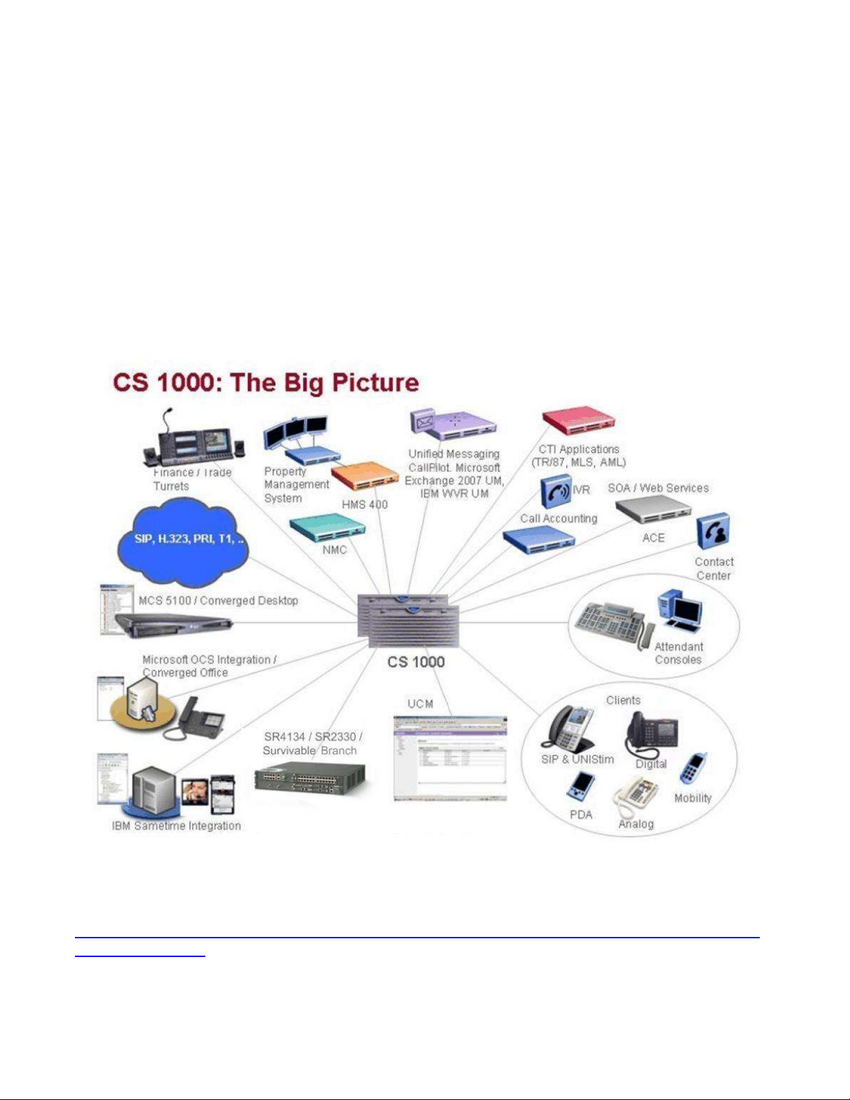
CS 1000
F
EATURE BACKGROUND
Communication Server 1000 4
Secure Router 4134 6
Secure Router 2330 7
F
EATURE DESCRIPTION
Multiservice Branch Router 7
Survivable SIP PSTN Gateway 8
INTRODUCTION 10
N
AVIGATION
SR 2330/4134 INTEROPERABILITY WITH CS 1000 11
SR 2330/4134, CS 1000
SSM O
SIP G
CS 1000 CONFIGURATION 16
SLG C
Steps 16
SSG C
Steps 26
NRS/SPS C
Steps 29
SIP C
CS 1000 P
4
AND SECURE ROUTER
7
10
PERATION
ATEWAY OPERATION
ONFIGURATION
ONFIGURATION
LIENTS CONFIGURATION
12
16
26
ONFIGURATION
ATCHES
34
2330/4134 4
4
COMPONENTS
13
29
34
11
SR 2330/4134 CONFIGURATION 35
Steps 35
NTML Examples 40
Example of Normal mode NTML (normal_cs1k.ntm) 40
Example of Backup mode NTML (backup_cs1k.ntm) 40
Page 4

New in this release
The following section details what’s new in Secure Router 2330/4134 as Communication
Server 1000 Survivable SIP Branch Solution (NN-SR-0001) for Release 10.2.
Features
The following sections detail the Secure Router 2330/4134 based CS 1000 branch solution and its
features.
Navigation
•
"CS 1000 and Secure Router 2330/4134" (page 4)
•
"Feature background" (page 4)
•
"Feature description" (page 7)
CS 1000 and Secure Router 2330/4134
4
In a centralized CS 1000 call server architecture, the remote branches make use of the call
processing resources available at a central location, generally located at the corporate
headquarters. The survivable branch solution based on Secure Router 4134 (SR 4134) and
Secure Router 2330 (SR 2330) provides business continuity to the branch office in the event
of a WAN connection outage to corporate headquarters. With this solution, employees at the
branch office can continue to use SIP phones to place and receive intra-site calls and calls
over the PSTN, including 911 calls.
Feature Background
Communication Server 1000
Nortel Communication Server 1000 is a server-based, full-featured IP PBX and the
cornerstone of Nortel Enterprise Unified Communication deployments. It provides the
benefits of a converged network plus advanced applications and over 750 world-class
telephony features. Fully distributed over IP LAN & WAN infrastructure with built-in reliability
and survivability, Communication Server 1000 supports business-critical applications,
including unified messaging, customer contact center, IVR, wireless VoIP and IP phones.
Key Features:
• Feature rich with over 750 call processing and telephony features
• Highly scalable with support for up to 22,500 IP users off of one Call Server, multiple
Call Servers networked together can support unlimited scalability
Page 5
• World class reliability and redundancy mechanisms - highly reliability architectural
elements that maximize network uptime with extensive redundancy mechanisms to
ensure network uptime including survivability options such as Campus and
Geographic redundancy to support network failover
• Extensive desktop portfolio includes; Wireless, Soft-phones, IP, Digital and Analog set
support, to meet diverse end-user requirements
• Supports business-critical applications, including IP Contact Center, CallPilot unified
messaging, and integrated services such as conferencing, one-number-follow-me
Personal Call Director, recorded announcement, network-wide attendant and
messaging
• Telephony integration with desktop application providers such as Microsoft and IBM
5
For more details please refer Nortel CS 1000 Product Webpage
http://products.nortel.com/go/product_content.jsp?segId=0&catId=null&parId=0&prod_id=511
21&locale=en-US
Page 6

6
Secure Router 4134
The Nortel Secure Router 4134 is a modular, multi-service platform that integrates multiple
networking functions, including routing, WAN, Ethernet switching, security and Voice over IP
(VoIP) into a single device. The platform's design ensures the consistently high throughput
required by voice, data or unified communications applications. The first device of its kind to
feature embedded Microsoft intelligence to simplify deployment of unified communications,
the Secure Router 4134 can reduce the number of devices needed at the branch or regional
site, generating substantial operational and capital cost savings for your business.
Key Features:
• Highly modular, high-performance platform - A wide range of LAN, WAN and
multiservice options to support converged branch, regional or headquarters
environments
• All-in-one voice, data and unified communications solution for enterprises – Nortel
SCS Server hosted on 4134 provides complete unified communications and data
networking solution for enterprise sites of up to 250 users by combining voice — call
server, conferencing, collaboration applications and PSTN gateway — with data and
security in an integrated, easy-to-manage platform.
• Only device of its kind to integrate Microsoft OCS services - Ideal for enterprises
considering deploying Microsoft OCS services in their remote branch sites
• Voice media gateway services - Enables connection to the Public Switched Telephone
Network (PSTN) or to traditional telephony devices
• Survivable voice services - Allows continued voice calling when the primary IP
connection is lost.
• Robust routing services - Full IPv4 and IPv6, BGP-4 and multicast implementation for
enterprise deployments
• Integrated Ethernet switching - High-density L2/L3 Gigabit, Fast Ethernet, as well as
Power over Ethernet. Up to 58 Gigabit or 72 Fast Ethernet ports supported.
• Wide range of WAN connectivity - Low and high-speed WAN options include serial,
T1/E1, DS3/T3, Channelized DS3/T3, HSSI and ISDN
• Integrated security - Stateful firewall and high-speed VPN encryption ensured the
integrity of both voice and data traffic
• High-reliability / resiliency - Hot-swappable modules, redundant power and
port/platform resiliency features deliver maximum uptime
• Unified Communications-ready platform - Superior small packet handling and low
latency ensures the quality of multimedia applications. Integrated VoIP and Microsoft
capabilities deliver on the promise of the unified communications branch.
For more details please refer Nortel SR 4134 Product Webpage
http://products.nortel.com/go/product_content.jsp?segId=0&catId=null&parId=0&prod_id=623
60&locale=en-US
Page 7

7
Secure Router 2330
The Nortel Secure Router 2330 is a cost reduced 1RU version of 4134 with almost same
feature set and lower capacity.
For more details please refer Nortel SR 2330 Product Webpage
http://products.nortel.com/go/product_content.jsp?segId=0&catId=null&parId=0&prod_id=693
60&locale=en-US
Feature Description
The Secure Routers 4134 and 2330 combines high performance, robust routing, flexible
WAN and voice media gateway connectivity and is targeted at enterprise branch and remote
site environments. A rich suite of routing services and advanced WAN functionality makes
these Secure Routers ideal for high-speed Internet access, private line WAN connectivity, IP
Telephony and multimedia, IPSec VPN, stateful firewall and data applications. The SR
2330/4134 survivable branch solution for Nortel CS 1000 provides business continuity to the
branch office in the event of a WAN connection outage to corporate headquarters.
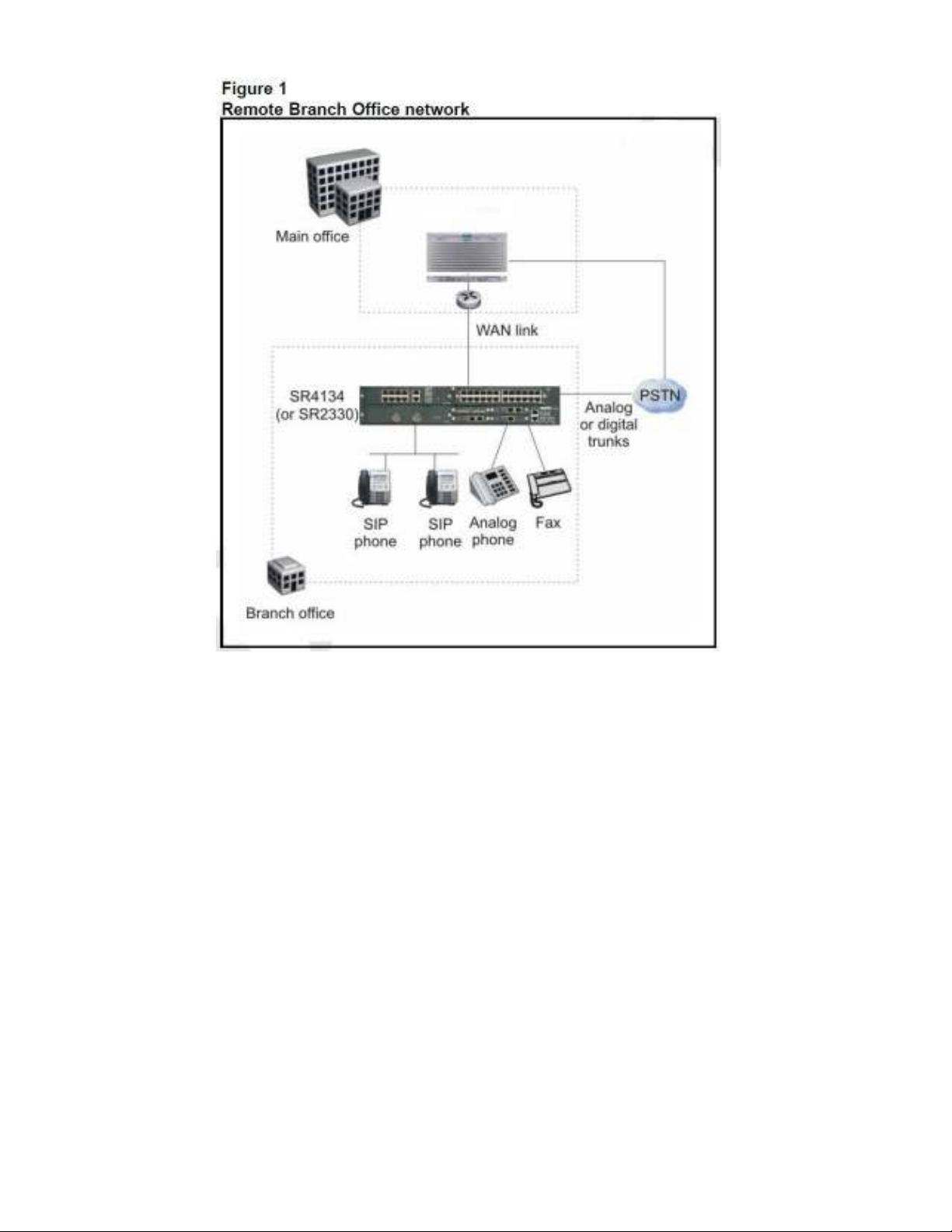
Multiservice Branch Router
Figure 1 shows a survivable branch office deployment with CS 1000 Call Server located at
the corporate main office or data center and Secure Router as branch office multi service
router providing data routing, security and survivable SIP-PSTN gateway.
Data routing services include a full IPv4 and IPv6 protocol set, including BGP-4 and
multicast capabilities. A full-function IPv6 implementation also enables deployment into
environments that require extended IP addressing with the same routing services.
Powerful, fully-integrated security features include VPN and firewalls for increased reliability
and user confidence. Capabilities include stateful packet firewall, detection and prevention of
more than 60 Distributed Denial of Service (DDoS) attacks, VPN hardware acceleration for
hub and spoke deployment over IPSec and VPN tunnels, and IPSec VPN data-encryption
services with AES, 3DES, DES, SHA-1, MD-5 and Diffie-Hellman support.
The SR also offers a set of integrated voice interfaces that allow connection to the public
switched telephone network (PSTN) as well as support of conventional TDM-based
telephony devices. T1/E1, FXS and FXO interfaces are all available for flexible telephony
connection with support for up to 128 simultaneous voice channels.
Page 8
8
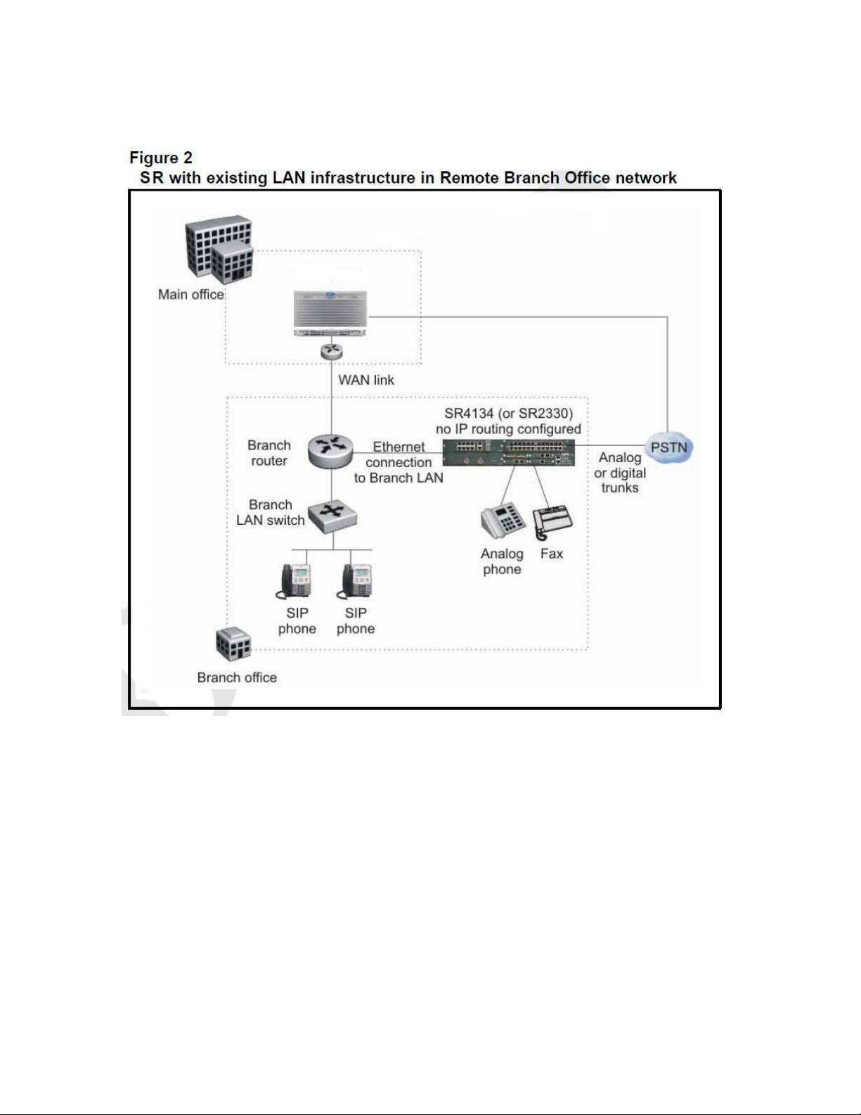
Survivable SIP PSTN Gateway
Figure 2 shows a survivable branch office deployment with CS 1000 Call Server located at
the corporate main office or data center and Secure Router providing survivable SIP-PSTN
gateway functionality complimenting the existing data infrastructure.
The SR 2330/4134 supports a variety of PSTN interfaces like T1/E1, BRI U, BRI S/T,
FXS/DID and FXO/CAMA for connectivity to PSTN and legacy PBXs and telephony devices.
Also supports a rich set of PSTN protocols including ISDN PRI, BRI, QSIG, T1 CAS, E1 R2
and analog signaling.
The Secure Router also includes a SIP Registrar and B2BUA based SIP Proxy which can
function as a backup SIP Server supporting up-to 300 SIP end-points including Nortel and
3rd-party SIP phones Nortel 1120E/1140E, Nortel 1535 Video phone, LG Nortel 6800/8800,
Polycom 330, SMC 3456, IP Dialog and Xlite. It can provide phone and call routing services
to the branch office when main office call server connectivity is lost and is already tested with
Nortel Call Servers and 3rd party Servers - CS 1000, CS 2100, CS 2000, A2E, SCS,
Page 9
9
Microsoft OCS and Broadsoft/Sylantro. Other main features include Call Admission Control,
PSTN fallback and memory based load control.
Page 10

10
Introduction
This document describes the quick start configuration of Nortel Secure Router 2330/4134
(Release 10.2) as survivable branch SIP-PSTN gateway for Nortel Communication Server
1000 (Release 6.0). For more information and detailed configuration guides on SR 2330, SR
4134 and CS 1000 go to the Nortel website:
www.nortel.com/support
Navigation
•
"SR 2330/4134 interoperability with CS 1000 (page 11)
•
"CS 1000 Configuration" (page 16)
•
"SR 2330/4134 Configuration" (page 35)
Page 11
11
SR 2330/4134 interoperability with CS 1000
SR 2330/4134, CS 1000 components
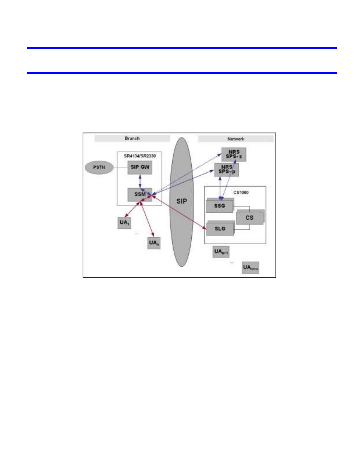
The following diagram shows the main components of Secure Router 2330/4134 and
Communication Server 1000.
SR has two modules SIP Gateway (SIP GW) and SIP Survivability Module (SSM) that
together interworks with CS 1000 to provide SIP survivable gateway functionality at the
branch. SSM is a software-only subsystem on the Secure Router through which SIP calls are
routed to the CS 1000. This module includes SIP B2BUA based proxy and SIP Registrar. SIP
GW is software and hardware subsystem on the Secure Router that provides PSTN
connectivity. The User Agents (UA) are SIP endpoints.
For detailed information about SSM operation please refer to Secure Router Release 10.2
guide NN47263-510 Configuration — SIP Survivability.
For detailed information on SIP GW please refer to Secure Router Release 10.2 guide
NN47263-508 Configuration — SIP Media Gateway.
The main CS 1000 components are Call Server (CS), SIP Signaling Gateway (SSG), SIP
Line Gateway (SLG), SIP Proxy Server (SPS) and Network Routing Service (NRS). SSG
handles SIP trunking and SLG takes care of SIP endpoints or SIP Lines.
Page 12
12
For detailed information on CS 1000 components and operation please refer to
Communication Server 1000 Release 6.0 user guides.
SSM Operation
The SSM operates in two modes - Normal (Connected) and Survivable (Isolated). In normal
mode, the SSM functions as an outbound proxy and proxies all SIP messages initiated from
the SIP phones (UA) and the SIP GW to the SLG located in the head office. SSM acts as a
B2BUA i.e. changes the Contact Header of SIP endpoint requests. Also the SIP endpoint
registrations to the SLG are “cached” locally. In survivable mode, the SSM supports SIP
server functionality to provide basic call features to the SIP endpoints at the branch, and also
supports local registrar functionality to store registrations.
SSM monitors the reachability of SLG by sending OPTIONS messages. If SLG is not
reachable or the link connected to SLG is down, SSM switches to the Survivable mode. The
SSM will continue to monitor the reachability of SLG as long as the link is up. Once it is
reachable, SSM will switch back to Normal mode.
SIP endpoints that have registered during Survivable mode will be registered with the SLG
after the Normal mode is established and next registration is attempted. SSM forces SIP
endpoints to register frequently (Default time 30 sec) in Survivable mode so that the
endpoints are registered to SLG as soon as SSM switches to Normal mode.
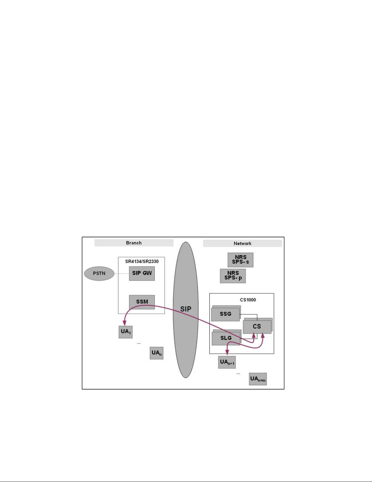
The above diagram shows the call flow of a SIP endpoint in branch, calling a SIP endpoint
connected to CS 1000 in Normal (Connected) mode. SSM proxies the calls to the SLG
received from the SIP endpoint. SSM also modifies the contact header in the INVITE
messages to point to the SSM bind IP address before forwarding the INVITE to the SLG to
Page 13

13
ensure that incoming calls are routed through the SSM. The same call flow holds good for
the call originated by the SIP endpoint connected to CS 1000. When the call arrives at SSM,
it will look for a mapped contact in its registration “cache” and routes the call to the UA. If
SSM does not find the mapped contact then it forwards the call to the configured default
gateway.
The following diagram shows the call flow between two SIP endpoints in branch in Normal
(Connected) mode.
SIP Gateway Operation
SIP GW interconnects SIP voice over IP networks with the PSTN. It also provides direct
connections for analog phones, faxes and modems. In branch office deployment for CS
1000, SIP GW registers with the currently active NRS/SPS to enable newly active SPS to
route calls to SIP GW. This is different than a user registration. SIP GW will monitor the
reachability of NRS/SPS to know that current active NRS/SPS. SIP GW does this by
sending OPTIONS messages to both primary and secondary NRS/SPS. If current active
SPS is not reachable, then gateway will switch to the other SPS as the currently active SPS.
The following diagram shows the call flow between a branch PSTN interface/device and SIP
endpoint connected to CS 1000. The SIP GW will route PSTN calls to an active SPS server
with Req-Uri having IP address of the active NRS/SPS via SSM. The SSM will then replace
the IP address with CS 1000 domain in ‘From’, ‘To’ and Req-Uri headers. If none of the NRS
SPSs is available, then SIP GW will send calls to SSM with Req-Uri having host as domain
configured for SLG in SSM e.g. nortel.com. This routing happens on the basis of entries
defined in Normal mode NTML dial plan. Normal mode dial plan defines routes for both
primary SPS and secondary SPS. SSM will choose the route from NTML depending upon
destination set in SIP messages by SIP GW.
Page 14

14
SSM will receive the incoming calls from SPS that are destined for PSTN. For such calls
SSM will not be able to find a mapped contact in its registration cache and hence routes the
call to configured default gateway which is SIP GW.
The following diagram shows the call flow between a branch PSTN interface/device and
branch SIP endpoint.
Page 15

The following diagram shows the call flow between branch PSTN interfaces/devices.
15
Page 16

16
CS 1000 Configuration
This section describes the configuration steps needed on CS 1000 components like SLG,
SSG and SPS for SR 2330/4134 based branch solution. There is no SR 2330/4134 specific
configuration required on CS 1000. Please refer to CS 1000 user guides for the detailed
configuration steps. The following diagram complete with IP addresses will be used as
reference for the configuration chapters.
SLG Configuration
Please refer to CS 1000 NN43001-508 SIP Line Fundamentals document for detailed
information on SLG configuration. There is no Secure Router specific configuration need to
done on SLG.
Steps
1. SIP Line (SIPL) feature depends on the following packages to be enabled in keycode.
Page 17

17
Package Type
Package
Mnemonic
Package
Number
Package Description
(New or
Existing
Applicable
Market
or Dependency)
SLS_Package
FFC
SIP_LINE_N
417 SIP Line Service New Global
139 Flexible Feature Codes Existing Global
415 Nortel SIP Line Package Existing
T_PKG
SIP_LINE_3
P_PKG
416 3rdParty SIP Line
Package
2. Deploy SIP Line software application on the Linux server
Existing
Figure SIPL 1 – SIP Line application deployment
Page 18

3. SIPL node configuration
18
+ Nodes: Servers, Media Cards
Figure SIPL 2 – SIPL node details
Figure SIPL 3 – General SIPL node configuration
Page 19

19
Figure SIPL 4 – SIP Line Gateway Service configuration
4. The SIP Line service must be enabled on a customer level
+ Customer --> Cus Number --> SIP Line Service
Figure SIPL 5 - SIP Line service inside Customer edit page
Page 20

20
Figure SIPL 6 - SIP Line service enable page
5. Password length configuration for SIP clients
+ Customer -->CUS# -->Flexible Feature Codes
Figure SIPL 7 - Password length configuration
Page 21

6. Enable ISDN for trunking
+ Customer --> CUS# --> Features Packages
21
Figure SIPL 8 – Enable ISDN feature
7. AML and VAS configuration
+ System --> Interfaces --> Application Module Link (must over 32)
Figure SIPL 9 – AML configuration
Page 22

+ System --> Interfaces --> Value Added Server --> Add -->Application Module Link
22
Figure SIPL 10 – AML configuration
8. D-channel/Route/Trunk for SIPL service
+ Routes and Trunks --> D-Channel
Figure SIPL 11 – D-Channel configuration for SIPL service
Page 23

23
+ Routes and Trunks --> Routes and Trunks --> CUS# --> Add route
Figure SIPL 12a – Route configuration for SIPL service
Figure SIPL 12b – Route configuration for SIPL service
Page 24

+ Routes and Trunks --> Routes and Trunks --> CUS# --> Route# --> Add Trunks
24
Figure SIPL 13 – Trunk configuration for SIPL service
9. SIPL phone configuration
+ Phones --> Add --> choice UEXT-SIPL phone --> preview
Figure SIPL 14a – SIPL phone configuration
Page 25

25
Figure SIPL 14b – SIPL phone configuration
Figure SIPL 14c – SIPL phone configuration
Page 26

26
SSG Configuration
Please refer to CS 1000 document for detailed information on SSG configuration. SIPL
needs a SSG server to route an external call to NRS (Network Routing Service). SIPGW and
H323GW endpoints will be configured in SSG to register on specific NRS server.
Steps
1) Deploy Signaling Server software application on the Linux server
2) SSG node configuration:
Figure SSG 1 – SSG application deployment
+ Nodes: Servers, Media Cards
Page 27

27
Figure SSG 2 – SSG node details
Figure SSG 3 – SIPGw and H323Gw endpoints configuration
Page 28

3) Specify a NRS server for SIPGw endpoint:
28
Figure SSG 4 – Specify a NRS server for SIPGw endpoint
4) Specify a GateKeeper server (NRS) for H323Gw endpoint:
Figure SSG 5 – Specify a GateKeeper server(NRS) for H323Gw endpoint
Page 29

29
NRS/SPS Configuration
Please refer to CS 1000 NN43001-130 Network Routing Service Fundamentals document for
detailed information on NRS/SPS configuration. The Network Routing Service (NRS)
provides routing services to both SIP and H.323-compliant devices. The NRS allows
customers to manage a single network dialing plan for SIP, H.323, and mixed SIP/H.323
networks. Therefore SIPGw and H323Gw endpoints of SSG and Secure Router endpoint
have to register on NRS server.
Steps
1) Deploy NRS software application on the Linux server
Figure NRS 1 – NRS application deployment
Page 30

2) NRS server configuration
30
Figure NRS 2 – NRS server configuration
3) SSG endpoint configuration
Figure NRS 2a – SSG endpoint configuration
Page 31

31
Figure NRS 2b – SSG endpoint configuration
4) Dialing plan routes for SSG endpoint configuration:
Figure NRS 3 – Dialing plan routes for SSG endpoint configuration
Page 32

5) SSG endpoint registration status
32
Figure NRS 4 – SSG endpoint registration status
6) SR 2330/4134 endpoint configuration
Figure NRS 5a – SR 2330/4134 endpoint configuration
Page 33

33
Figure NRS 5b – SR 2330/4134 endpoint configuration
7) Dialing plan routes for SR 2330/4134 endpoint configuration:
Figure NRS 6 – Dialing plan routes for SR 2330/4134 endpoint configuration
Page 34

8) SR 2330/4134 endpoint registration status
34
Figure NRS 7 – SR 2330/4134 endpoint registration status
SIP Clients Configuration
Configure the branch SIP endpoints to use SSM bind IP address as the Outbound Proxy
ie.100.20.42.80:5060.
Please ensure that the SIP username and domain need to match the CS 1000 SIP Line
settings. username@domain represents a globally unique identifier for a SIP user.
CS 1000 Patches
Below patches are needed for version CS: 600R LB: 6.00.18 LA: 6.00.18 of the CS 1000
system:
nortel-CS 1000-sps-6.00.18.17-01.i386.000
nortel-CS 1000-vtrk-6.00.18.23-08.i386.000
For higher versions of CS 1000, please refer Meridian PEP Library at
http://qtcfs0n6.ca.nortel.com/mpl/core_menu_view.cfm
If you don’t find the required versions in PEP Library please contact Nortel support.
Page 35

35
SR 2330/4134 Configuration
This section describes the configuration steps needed for SR 2330/4134 for CS 1000 branch
solution. The following diagram complete with IP addresses will be used as reference for this
chapter.
For configuration details on SSM, please refer to Secure Router Release 10.2 guide
NN47263-510 Configuration — SIP Survivability.
For configuration details on SIP Gateway (SIP GW) please refer to Secure Router Release
10.2 guide NN47263-508 Configuration — SIP Media Gateway.
Steps
1. Configure the Ethernet interface for connection to the SIP server and SIP phones:
configure terminal
interface ethernet 0/1
ip address 100.20.42.80 255.255.255.224
exit ethernet
Page 36

2. Configure a default route to the branch router:
ip route 0.0.0.0/0 100.20.42.65
3. Configure the SIP Media Gateway to listen on port 5070:
voice service voip
sip
bind all ipv4:100.20.42.80:5070
exit sip
exit voip
4. To configure the SIP Survivability Module, bind the IP interface for SIP traffic using
default port 5060:
voice service voip
ssm
bind ip ipv4:100.20.42.80
5. Enable SSM:
enable
6. Configure dialpan. Normal mode NTML is used to route gateway calls to SPSs and to
replace IP address of SPS to domain name. Survivable dial plan is optional.
Configure it only if number translation is required in survivable mode.
dialplan
load normal normal_cs1k.ntm
load survivable backup_cs1k.ntm
exit dialplan
7. Enable SSM keepalives to configure SLG ip-address and monitor connectivity with
SLG:
sip-server
keepalive-server ipv4:100.20.45.167:5070 interval 60 retries 2 transport udp
8. Configure SSM domain to specify SLG domain:
domain dns:interop.com
exit sip-server
9. Configure SSM Call Admission Control on the WAN interface connecting SLG:
36
Page 37

cac
max-calls ethernet0/1 256
10. Configure the CAC exclusion pool that identifies the IP address range of the SIP
endpoints that use SSM:
exclude-pool 100.20.47.0 255.255.255.0
exit cac
11. Point the SSM to the SIP Media Gateway IP interface as the default gateway
(specifying the non-default port), Port should be same as configured for gateway’s
listening port in step 3.:
default-gateway ipv4:100.20.42.80:5070 transport udp
exit ssm
exit voip
12. Configure the outbound proxy on the SIP Media Gateway to point to the SSM:
sip-ua
outbound-proxy ipv4:100.20.42.80:5060
13. Configure the primary and secondary SPS for the SIP Media Gateway:
(No need to configure secondary sip-server if there is only one SPS used):
sip-server ipv4:100.20.42.77:5060
sip-server ipv4:100.20.42.82:5060 secondary
14. Configure authentication parameters to be used for gateway to SPS calls and
registration:
authentication SR 4134 1234
15. Configure keepalive to monitor primary and secondary SPS connectivity:
keepalive target sip-server
keepalive target sip-server secondary
16. Configure dynamic registration from SR gateway to active SPS.
register dynamic
exit sip-ua
17. Configure voice ports for FXS phones
(example for 2 FXS phones connected to port 2/1 and 2/2)
voice-port 2/1
signal loop-start
station number 74001
37
Page 38

no shutdown
exit voice-port
voice-port 2/2
signal loop-start
station number 74002
no shutdown
exit voice-port
18. Configure PRI interface bundle.
(example to configure PRI E1 bundle on port 3/1 with switch-type as qsig)
interface bundle E1PSTN
link pri_e1 3/1 voice
isdn
switch-type primary-qsig
activate
exit isdn
exit bundle
19. Optional translation profile configuration.
a. Configure translation profile for PSTN to SPS calls. (Example to translate 335..
number to 5.. numbers.) There can be more that 1 rules which can be called or calling
or both numbers.
voice translation-rule 100
rule 1 /335/ /5/
exit translation-rule
voice translation-profile pstn2sps
translate calling 100
translate called 100
exit translation-profile
b. Configure translation profile for SPS to PSTN calls. (Example to translate 5..
numbers to 335..)
voice translation-rule 200
rule 1 /5/ /335/
exit translation-rule
voice translation-profile sps2pstn
translate calling 200
translate called 200
exit translation-profile
38
Page 39

39
20. Configure Dial peer for FXS phones:
dial-peer voice pots 1
destination-pattern 74001
port 2/1
forward-digits all
no shutdown
exit pots
dial-peer voice pots 2
destination-pattern 74002
port 2/2
forward-digits all
no shutdown
exit pots
21. Configure Dial peer for PRI interface and (optionally) apply translation profile.
(Following dial peer is for calls coming from SPS with a number starting with 53 to be
translated to a number starting with 3353 before sending on PRI. Don’t use translation
profile if no translation required. )
dial-peer voice pots 3
destination-pattern 53.%
port 3/1
forward-digits all
no shutdown
translation-profile outgoing sps2pstn
exit pots
(Following dial peer is for calls coming from PSTN with a number starting with 3353 to
be translated to a number starting with 53 before sending to SPS. Don’t use
translation profile if no translation required. )
dial-peer voice pots 4
destination-pattern 3353.%
port 3/1
forward-digits all
no shutdown
translation-profile incoming pstn2sr
exit pots
If no translation required than instead of dial-peer 3 and 4, only 1 dial peer is required with
destination-pattern 53.% (assuming that all PRI numbers are starting with 53).
Following is an example if a 911 call is to be routed to PRI interface.
dial-peer voice pots 5
destination-pattern 911
port 3/1
forward-digits all
no shutdown
Page 40

NTML Examples
Example of Normal mode NTML (normal_cs1k.ntm)
This NTML is used by SSM to route gateway calls to active SPS (100.20.42.77 or
100.20.42.82) with domain nortel.com.
<translation>
<address-switch field = "original-destination" subfield = "host">
<address is = "100.20.42.77">
<replace string=" nortel.com" field="destination" subfield="host">
<replace string=" nortel.com" field="origin" subfield="host">
<replace string=" nortel.com" field="original-destination" subfield="host">
<route host="100.20.42.77" add-route="yes" replace-host ="no"/>
</replace>
</replace>
</replace>
</address>
<address is = "100.20.42.82">
<replace string=" nortel.com" field="destination" subfield="host">
<replace string=" nortel.com" field="origin" subfield="host">
<replace string=" nortel.com" field="original-destination" subfield="host">
<route host="100.20.42.82" add-route="yes" replace-host ="no"/>
</replace>
</replace>
</replace>
</address>
</address-switch>
</translation>
40
Example of Backup mode NTML (backup_cs1k.ntm)
This NTML is optional. Here is an example assuming that calls with certain prefix in backup
mode needs to be converted to a 5 digit number extension.
<translation>
<number-switch>
<number is = "967?????">
<drop literals = "3"/>
</number>
<number is = "613967?????">
<drop literals = "6"/>
</number>
<number is = "1613967?????">
<drop literals = "7"/>
</number>
</number-switch>
</translation>
 Loading...