

Page 1

Part No. 206379-A
September 1999
4401 Great America Parkway
Santa Clara, CA 95054
Installation and Reference for the BayStack 21 PCI 10/100 Adapter w/WOL
Page 2

Copyright © 1999 Nortel Networks.
All rights reserved. Sep tember 1999.
The information in this docume nt is subject to change without notice. The statements, configurations, technical data,
and recommendations in this document are believed to be accur ate and reliable, but are presented without express or
implied warranty. Users mu st take full responsibi lity for their applications of any products specified in this document.
The information in this docume nt is proprietary to Nortel Networks NA In c.
Trademarks
NORTEL NETWORKS is a trademar k of Norte l Networks.
Bay Networks is a registered trademark and Ba yStack and the Nortel N etworks logo are trademarks of Nortel
Networks .
Microsoft, Windows, and Windows NT are registered trademarks of Microsoft Corporation.
All other trademarks and registered tr ademarks are the property of their respectiv e owners.
USA Requir e m e nts Only
Federal Communications Commission (FCC) Compliance Notice: Radio Frequency Notice
This dev ice complies with Part 15 of the FCC R ules. Operation is subject to the following tw o conditions:
• This dev ice may not cause harmful interference.
• This device must accept any interference received, includi ng interferenc e that may cause undesired
operati on.
Note: This equipment has been tested and found to comply with the limits for a Class B digital device, pursuant to
Part 15 of the FCC Rules. These limit s are designed to provide reasonable pr otection against harmful interferenc e in a
residen tial insta ll atio n. This equipm ent ge ner at es, us es and can ra dia te rad io fre que ncy en er g y and , if not in stal le d and
used in accordance with the instructions, m a y cause harmful int erference to radio communicati ons. However, th ere is
no guarant ee that interference will not occur in a particular ins tallation. If t his equipment does ca use harmful
interf erence to radio or television receptio n, which can be determined by turning the equipment off and on, the user is
encourage d to try to correct the interference by one or more of the following measures:
• Reorient o r relocate the re ceiving ante nna.
• Increase the separation between the equipment and recei ver.
• Connect the equipment into a n outlet on a circuit different from that to which the receiver is connected.
• Consult the dealer or an experienced radio/ TV technician for help.
EN 55 022 Statement
This is to cer tify that the N o rtel Networ ks BayStack 21 PCI 10/100 Adapter w/WOL is shielded agains t the
generation of radio interference in accordance with the application of Council Directive 89/336/EEC, Article 4a.
Conformity is declared by the application of EN 55 022 Class B (CISPR 22).
Warning: This is a Class A produc t. In a domestic environment , this product may cause radio interference, in whi ch
case, the user may be required to take appropriate measures.
ii
206379-A
Page 3

EC Declaration of Conformity
This product conforms to the provisions of Council Directive 89/336/EEC and 73/23/EEC. The Declaration of
Conformit y is availa ble on the Nortel Networks World Wide Web si te at http://libra2.corpwest.baynetw orks.com/
cgi-bin/ndCGI.exe/DocView/.
Voluntary Control Council for Interference (VCCI) Statement
Voluntary Control Council for Interference (VCCI) Statement
This is a Class A product based on the standard of the Voluntary Control Council for Interference by Information
Technology Equipment (VCCI). If this equipment is used in a dom estic env ironment, radio disturbance may ari se.
When such trouble occurs, the user may be required to take corrective actions.
Canadian Department of Communications Radio Interference
Regulations
This digital apparatus (BayStack 21 PCI 10/100 Adapter w/WOL) do not exceed the Class A limits for radio-noise
emissions from digital apparatus as set out in the Radio Interference Regulations of the Canadian D epartment of
Communications.
Règlement sur le brouillage radioélectrique du ministère des
Communications
Cet appareil numérique (BayStack 21 PCI 10/100 Adapter w/WOL) respecte les limites de bruits radioélectriques
visant les ap par ei ls num ériq ues de cl asse A prescr it es dans le Règ le ment sur le br oui llag e ra dio élect r ique du m inis tè re
des Communications du Canada.
206379-A
iii
Page 4

Electromagnetic Interference (EMI) Statement
Wichtige Sicherheitshinweise
1. Bitte lesen Sie diese Hinweis e sorgfaltig durch.
2. Heben Sie diese Anleitung fur den spateren Gebrauch auf.
3. Vor jedem R einigen ist das Gerat vom Stromnetz zu trennen. Verwenden Sie keine Flussigoder Aerosolreiniger.
Am besten eignet sich ein angefeuchtetes Tuch zur Reinigung.
4. Um eine Beschadigung des Gerate s zu vermeiden sollten Sie nur Zubehorteile verwenden, die vom Hers teller
zugelassen sind.
5. Da s G e rat ist vor Feuchtigke it zu sc hu tzen.
6. Bei der Aufstellung des Gerat es ist auf sicheren Stand zu achten. Ein Kippen oder Fallen konnte Verletzungen
hervor rufen. Verwenden Sie nur sichere Standorte und beachten Sie die Aufstellhinweise des Herstellers.
7. Die Beluftungsoffnungen dienen der Luftzirkulation die das Gerat vor Uberhitzung schutzt. Sorgen Sie dafur,
daB diese Of fnungen nicht ab gedeckt werden.
8. Beachten Sie beim AnschluB an das Str om netz die AnschluBwerte.
9. Die Netzanschlusteckdose muB aus Grunden der elektrischen Sicherheit einen Schutzleiterkontakt haben.
10. Verlegen Sie die N etzanschluBle itung so, da B niemand daruber fallen kann. Es sollte auch nic hts auf der Leitung
abgestellt werden.
11. Alle Hinweise und Warnungen, die sic h am Geraten befinden sind zu beachten.
12. Wird das Gerat uber einen langeren Zeitraum nicht benutzt, sollten Sie es vom Stromnetztrennen. Somit wird im
Falle einer Uberspannung eine Beschadigung vermieden.
13. Durch die Luf tungsoffnungen durfen niemals Ge genstande oder Flussigkeiten in das Gerat gelange n.
Dies konnt e einen Brand bzw. elektrischen Schlag auslosen.
14. Offnen sie niemals das Gerat. Das Gerat darf aus Grunden der elektrischen Sicherheit nur von authorisiertem
Servicep ersonal geoffnet werden.
iv
206379-A
Page 5

15. Wenn folgende Situationen auftreten ist das Gera t vom Stromnetz zu trennen und von einer qualifizierten
Servicestelle zu uberprufen:
a. Netzkabel oder Netzstecker sind beschadigt.
b. Flussigkeit ist in das Gerat eingedrungen.
c. Das Gerat war Feuchtigkeit ausgesetzt.
d. Wenn das Gerat nicht der Bedienungsanleitung entsprechend funktioniert oder Sie mit Hilfedieser Anle itung
keine Verbesserung erzielen.
e. Das Gerat ist gefallen und/oder das Gehause ist beschadigt.
f. Wenn das Gerat deutliche Anzeichen eines Defektes aufweist.
16. Bei Reparaturen durfen nur Or ginalersatzteile bzw. den Orginalteilen entsprechende Te ile verwendet werden.
Der Einsatz von ungeeigneten Ersatzteilen kan n eine weitere Beschadigung hervorrufen.
17. Bei Reparaturen durfen nur Or ginalersatzteile bzw. den Orginalteilen entsprechende Te ile verwendet werden.
Der Einsatz von ungeeigneten Ersatzteilen kan n eine weitere Beschadigung hervorrufen.
18. Wenden Sie sich mit allen Fragen die Service und Repartur betreffen an Ihren Servicepartner. Somit stellen Sie
die Betriebssicherheit des Gerates sicher.
19. Zum NetzanschluB dieses Gera tes ist eine geprufte Leitung zu verw enden. Fur einen Nen nstrom bis 6A und
einem Gerategewicht groBer 3kg ist eine Leitung nicht leichter als H05VV-F, 3G, 0.75mm 2 einzusetzen. Der
arbeitsplatzbezogene Schalldruckpegel nach DIN 45 635 Teil 1000 betragt 70dB(A) oder weniger.
Restricted Rights Legend
Use, duplication, or disclosure by the United States Government is subject to restrictions as set forth in subparag raph
(c)(1)(ii) of the Rights in Techni cal Data and Computer Software clause at DFARS 252.227-7013.
Notwithstanding any other license agreement that may pertain to, or accompany the delivery of, this computer
software, the rights of the United States Governm ent regardi ng its use, reproduction, and di sclosure are as set forth in
the Commercial Computer Softw are-Restric ted Rights clause at FAR 52.227-19.
Statement of Conditions
In the interest of im proving internal desig n , operational function, and /or reliabil ity, Nortel Networks NA Inc. reserves
the right to m ake changes to the products described in this document without notice.
Nortel Net w orks NA Inc. does not assume any liability that may occur due to the use or application of the product(s)
or circuit layout(s) described herein.
Portions of the code in this software product are Copyright © 1988, Regents of the Uni versity of California. All rights
reserv ed. Redistribution and use in source and binary forms of such portions are permitted, provided that the above
copyrig ht not ic e an d th is par agr ap h ar e dupli ca te d in all su ch f or ms and th at a ny doc um enta ti on, adve rt is in g mat eria ls ,
and other m ateri al s rel at ed to such di stri b utio n and use ac know led ge t hat s uch p or tions of t he sof t war e we re de v el oped
by the U niversity of California, Berke ley. The name of the University may not be used to endorse or pr om ote products
deri ved from such portions of the software without specific prior w ritten permission.
SUCH PORTIONS OF THE SOFTWARE ARE PROVIDED “AS IS” AND WITHOUT ANY EXPRESS OR
IMPLIED WARRANTIES, INCLUDING, WITHOUT LIMITATION, THE IMPLIED WARRANTIES OF
MERCHANTABILITY AND FITNESS FOR A PA RTICULAR PURPOSE.
206379-A
v
Page 6

Nortel Networks NA Inc. Software License Agreement
NOTICE: Please carefully read this license agreement before copying or using the accompanying software or
instal ling the hardware unit with pre-enabled software (each of which is r eferred to as “Software” in t h is Agreement).
BY COPYING OR USING THE SOFTWARE, YOU ACCEPT ALL OF THE TERMS AND CONDITIONS OF
THIS LICENSE AGREEMENT. THE TERMS EXPRESSED IN THIS AGREEMENT ARE THE ONLY TERMS
UNDER WHICH NORTEL NETWORKS WILL PERM IT YOU TO USE THE SOFTWARE. If you do not accept
these ter ms and conditions, return the product, unused and in the original shipping container, within 30 days of
purchase to obtain a credit for the full purchase price.
1. License Grant. Nortel N e tworks NA Inc. (“Nortel Networks”) grants the end user of the Sof tware (“Licensee”) a
personal, no ne xcl usi v e , nontr ans fe rabl e li cense: a) t o use th e Softw are eit her on a si ngl e compu ter or, if applica bl e, on
a single authorized device identified by host ID, for which it was originally acquired; b) to copy the Software solely
for backup purposes in suppo rt of authorize d use of the Software; and c) to use and copy the associated user manual
solely in support o f authorized use of the Software b y Licensee. T his license applies to the Software only and does not
extend to Nortel Networks Agent software or other Nortel Networks software products. Nortel Networks Agent
software or other Nortel Ne tworks software products are licensed for use under the terms of the applicable No rtel
Networks NA Inc. Software Lic ense Agreement that accompa nies such software and upon payment by the end user of
the applicable license fees for such software.
2. Restrictions on use; reservation of right s. The Software and user manuals are protected under copyright laws.
Nortel Net w orks and/or its licensors retain all title and o w nership in both the Software and user manuals, including
any re visions made by Nortel Networks or its licensors. The copyright notice must be reproduced and included with
any copy of any p orti on of the Soft war e or user manual s. Lic ensee m ay not m odify, trans la te , decom pile , disa ss embl e,
use for any competitive analysis, reverse engineer, distribute, or create derivative works from the Software or user
manuals or any copy, in whole or in p art. Except as e xpressly provi ded in this Agreem ent, Licensee may not copy or
transfe r the Software or user manuals, in whole or in part. The Software and user manuals embody Nortel Networks’
and its licensors’ c onfidentia l and proprietary intellectual propert y. Lic ensee shall not sublicense, assign, or otherwise
disclose to any third party the Software, or any informati on about the operation, design, performance, or
implementation of the Software and user manuals that is confidential to Nortel Networks and its licensors; however,
Licensee m ay grant permission to it s consultants, subcontrac tors, and agents to use the Software a t Licensee’s facility,
provided they have agreed to use the Software only in accordance with the terms of this l icense.
3. Limited warranty. Nortel Net w orks warrants each i tem of Software, as de livered by Nortel Networks and properly
instal led and operated on Nortel Networks h ardware or other equipment it is originally licensed for, to function
substantially as described in its accompan ying user manual dur ing its warranty period, which be gins on the date
Softwar e is f ir st shi ppe d to Licen see . I f any it em of Soft wa re fai l s to so func ti on during i ts warr anty pe ri od, as the so le
remedy Norte l Net wor ks will at it s discr et ion pro vi de a suita bl e fix , pat ch , or worka ro und fo r the p roble m that may be
included in a future Software release. No rtel Networks further warra n ts to Licensee tha t the media on which the
Softwar e is provided will be free from defects in materials and workmanship under normal use for a period of 90 days
from the date Software is first shipped to Licensee. Nort el N etworks will replace defective media at no ch arge if it is
returned to Nortel Networks during the w arranty period along with proof of the date of shipment . This warranty does
not apply if the media has been damaged as a result of accident, misuse, or abuse. The Licensee assumes all
resp on s ib ility for se le ct ion of the Sof t ware to achieve Li censee’s inten ded results and for the installa ti on , use, and
results obtained from the Software. Nortel Ne tworks does not war rant a) that the functions contained in the software
will meet the Licensee’s requirements, b) that the Software will operate in the hardware or software combinations that
the Licensee may select, c) that the operat ion of the Software will be uninterrupted or error free, or d) that all defects
in the ope rati on of th e Sof twar e wi ll be c orr ecte d. Nort el Net works i s n ot o bli g ated t o re medy an y Sof tw are de fe ct tha t
cannot be re produced with the latest Software release. These wa rranties do not apply to the Software if it has been (i)
altere d, except by Nortel Networks or in accordance with its instructions; (ii) used in conjunction wi th another
vi
206379-A
Page 7

vendor’s product, resulting in the defect; or (iii ) dam aged by improper environme nt, abuse, misuse, accident, or
negligence. THE FOREGOING WARRANTIES AND LIMITATIONS ARE EXCLUSIVE REMEDIES AND ARE
IN LIEU OF ALL OTHER WARRANTIES EXPRESS OR IMPLIED, INCLUDING WITHOUT LIMITA TION ANY
WARRANTY OF MERCHANTABILITY OR FITNESS FOR A PARTICULAR PURPOSE. Licensee is responsible
for the security of its own data and information and for mai ntaining adequate procedures apart from the Software to
reconst ruct lost or altered files, d ata, or programs.
4. Limitation of liability. IN NO EVENT WILL NORTEL NETWORKS OR ITS LICENSORS BE LIABLE FOR
ANY COST OF SUBSTITUTE PROCUREMENT; SPECIAL, INDIRECT, INCI DENTAL, OR CONSEQUENTIAL
DAMAGES; OR ANY DAMAGES RESUL TING FROM INACCURATE OR LOST DATA OR LOSS OF USE OR
PROFITS ARISI NG OUT OF OR IN CONNECTION WITH THE PERFORMANCE OF THE SOFTWARE, EVEN
IF NORTEL NETW ORKS HAS BEEN ADVISED OF THE POSSIBILITY OF SUCH DAMAGES. IN NO EVENT
SHALL THE LIABILITY OF NORTEL NETWORKS RELATING TO THE SOFTWARE OR THIS AGREEMENT
EXCEED THE PRICE PAID TO NORTEL NETWORKS FOR THE SOFTWARE LICENSE.
5. Government Licensees. This pr o visi on a pplie s t o a ll Sof tw ar e and do cum enta ti on acqui red di rectl y o r indi r ectl y b y
or on be half of the Un ited States Government. The Software and documentation are com m ercial products, licensed on
the open market at market prices, and were de veloped entirely at private expense and w ithout the use of any U .S.
Government funds. The license to the U.S. Government is granted only wi th restricte d rights, and use, duplication, or
disclos ure by the U.S. Government is subject to the restrictions set forth in subpara graph (c)(1) of th e Com mercial
Computer Sof tware––Restr icted Rights clause of FAR 52.227-19 a nd the limitations set out in this license for civilian
agencies , and subparagrap h (c)(1)(ii) of the R ights in T echnical Data and Co mp uter Software cl ause of DFARS
252.227- 7013, for agencies of the Department of Defense or their successors, whichever is applicable.
6. Use of Software in the European Community. This prov is io n ap plies to al l So f tw are acquired for use wi thin the
European Community. If Licensee uses the Software withi n a country in the Euro pean Community, the Software
Directive enacted b y the Council of Europ ean Communities Directive da ted 14 May, 1991, will apply to the
examination of the Software to facilit ate interoperability. Licensee agre es to notify Nortel Networks of any su ch
intended examination of the Software and ma y p rocure support and assistance from Nor tel Networks.
7. Term and termination. This license is effective unt il terminated; h owever, all of the restrictions w ith respect to
Nortel N etworks’ copyright in the Software and user man uals will cease being effectiv e at the d ate of expiration of the
Nortel Networks copyright; those restrictions relating to use and disclosure of Nortel Networks’ confidential
information shall continue in effect. Licensee may terminate this license at any time. The license will automatically
terminate if Licensee fails to comply with any of the terms and conditions of the license. Upon termination for any
reason, Licensee will immediately destroy or return to Nortel Networks t h e Software, user ma nuals, and all copies.
Nortel Networks is not liable to Licensee fo r damages in any form solely by reason of the termin ation of this lic ense.
8. Export and Re-export. Licensee agrees not to export, directly or indirectly, the Software or relat ed technical data
or information without first obtaining any required export licenses or other governmental approvals. Without limiting
the foregoing, Licen see, on behalf of itself and its subsidiaries a nd affiliates, agrees that it will not, w ithout fir s t
obtaining all export licenses and appro vals required by the U.S. Gove rnment: (i) export, re-expo rt, transfer, or diver t
any such Sof tware or technical data, or any direct product thereof, to any country to which such exports or re-exports
are rest ricted or embar goed under United States export control laws and regulations, or to any natio nal or resident of
such rest ricted or embargoed countries; or (ii) provide the Software or related tec hnical data or in formation to any
military end user or for any mi litary end use, including the design, developm ent, or production of any chemical,
nuclear, or biological weapons.
206379-A
vii
Page 8

9. General. If any provision of this Agreement is held to be invalid or unenforceable by a court of competent
jurisdiction, the remainder of the provisions of this Agreement shall remain in full force and effect. This Agreement
will be go verned by the la w s of the state of California.
Should you have any questions concerning this Agreement, co ntact Nortel Networks, 4401 Great A m erica Parkway,
P.O. Box 58185, Santa Clara, Califor nia 95054-8185.
LICENSEE ACKNOWLEDGES THAT LICENSEE HAS READ THIS AGREEMENT, UNDERSTANDS IT, AND
AGREES TO BE BOUND BY ITS TERMS AND CONDITIONS. LICENSEE FUR THER AGREES THAT THIS
AGREEMENT IS THE ENTIRE AND EXCLUSIVE AGREEMENT BETWEEN NORTEL NETWORKS AND
LICENSEE, WHICH SUPERSEDES ALL PRIOR ORAL AND WRITTEN AGREEMENTS AND
COMMUNICATIONS BETWEEN THE PARTIES PERTAINING TO THE SUBJECT MATTER OF THIS
AGREEMENT. NO DIFFERENT OR ADDITIONAL TERMS WILL BE ENFORCEABLE AGAINST NORTEL
NETWORKS UNLESS NORTEL NETWORKS GIVES ITS EXPRESS WRITTEN CONSENT, INCLUDING AN
EXPRESS WAIVER OF THE TERMS OF THIS AGREEMENT.
viii
206379-A
Page 9

Contents
Preface
Before You Begin ............................................................................................................xvii
Text Conventions ................... ............ ............ ............ ............ ............ ........... ..................xvii
Technical Publications ...................................................................................................xviii
How to Get Help ............................................................................................................xviii
Chapter 1
Introduction
BayStack 21 PCI Network Interface Card Overview .......................................................1-1
Product Features ............................................................................................................1-2
Product Description ........................................................................................................1-2
BayStack 21 Network Card ......................................................................................1-2
RJ-45 Ethernet Port ...........................................................................................1-2
LEDs .................................................................................................................. 1-3
WOL Cable and Connector ................................................................................1-4
System Require men ts ......................................... ................................. ............ ........1-5
Operating Environments ..........................................................................................1-5
Cable Requi re me n ts .......... ............ ................................. ................................. ........1-6
Fast Ethernet Cables (100 Mb/s) .......................................................................1-6
Ethernet Cables (10 Mb/s) ................................................................................. 1-6
Chapter 2
Hardware Installati on
Package Contents ..........................................................................................................2-1
Installing the BayStack 21 PCI Network Interface Card ..................................................2-2
Connecting the WOL Cable ..................................................................................... 2-3
206379-A
ix
Page 10

Chapter 3
Software Installation
Preinstallation ................................................................................................................. 3-2
Installing the Network Driver in a Windows 95 Environment ..........................................3-2
Configuring the Windows 95 Environment ............................. ....... ....... .. .......... ....... .3-6
Configuring the Workstation Identification .........................................................3-6
Configuring the Network Properties .................................................................. 3-8
Installing the Network Driver in a Windows 98 Environment ........................................3-12
Configuring the Windows 98 Environment ............................. ....... ....... .. .......... ......3-16
Configuring the Network Properties ................................................................3-16
Installing the Network Driver in a Windows NT Environment . ...................................... 3-18
Configuring the Network Properties ....................................................................... 3 -21
Installing the Network Driver in a Novell NetWare 4.x Environment .............................3 -23
Installing the Network Driver in a Novell NetWare Server ......................................3-23
Specifying Driver Parameters ..........................................................................3-24
Installing the Network Card in a Novell NetWare Client .........................................3 -25
Chapter 4
Using the WOL Feature
Setting Up the Workstation .............................................................................................4-1
Running the WOL Feature ..................................................................... ....... ..... ....... ......4-2
Chapter 5
Troubleshooting
Diagnostic LEDs .............................................................................................................5-1
Hardwar e Iss ues .................. ................................. ............ ................................. ............ .5-2
Software Issues ..............................................................................................................5-2
Appendix A
Technical Spec ifications
Product Specifications ...................................................................................................A-1
Software Drivers ............................................................................................................A-2
x
206379-A
Page 11

Appendix B
Novell NetWare Reference Information
Novell NetWare Server AUTOEXEC.NCF Files and Parameters ..................................B-1
Sample AUTOEXEC.NCF Files ........................................................................B-1
Sample AUTOEXEC.NCF File Parameters ....................................................... B-3
Novell NetWare Client Commands and NET.CFG File ..................................................B- 5
Client Commands ............................................................................................. B-5
Sample NET.CFG Files .....................................................................................B-5
Index
206379-A
xi
Page 12

xii
206379-A
Page 13

Figures
Figure 1-1. Link and Activity LEDs .............................................................................1-3
Figure 1-2. WOL Cable ..............................................................................................1-4
Figure 1 -3. WOL Connector .......................................................................................1-4
Figure 3 -1. New Hardware Found Window—Generic ................................................3-2
Figure 3 -2. New Hardware Found Window—BayStack 21 Network Card .. ................3-3
Figure 3 -3. Update Device Driver Wizard Dialog Box—Gener ic ................................3-3
Figure 3-4. Update D evice Driver Wizard Dial og Box—BayStack 21 Netwo rk Card ..3-4
Figure 3-5. Copying Files Dialog Box .........................................................................3-5
Figure 3 -6. Network Dialog Box—Identification Tab .. .................................................3-6
Figure 3 -7. System Settings Change Dialog Box .......................................................3-7
Figure 3-8. Network Dialog Box—Configuration Tab .................................................. 3-8
Figure 3 -9. Select Network Compone nt Type Dialog Box ..........................................3-9
Figure 3-10. Select Network Protocol Dialog Box ........................................................3-9
Figure 3-11. Configuration Tab, BayStack 21 Network Card Selected .......................3-10
Figure 3 -12. TCP/IP Propert ies Dialog Box . ..............................................................3-11
Figure 3 -13. New Hardware Found Window—Generic ..............................................3-12
Figure 3 -14. New Hardware Found Window—BayStack 21 Network Card .. ..............3-13
Figure 3-15. Copying Files Dialog Box .......................................................................3-13
Figure 3-16. Copying Files Dialog Box .......................................................................3-14
Figure 3 -17. New Hardware Found Dialog Box ..........................................................3-14
Figure 3 -18. System Settings Change Dialog Box . ....................................................3 -15
Figure 3-19. Network Dialog Box—Configuration Tab ................................................3 -16
Figure 3 -20. TCP/IP Propert ies Dialog Box . ..............................................................3-17
Figure 3-21. Network Dialog Box—Adapters Tab ....................................................... 3 -18
Figure 3 -22. Select Network Adapter Dialog Box .......................................................3-19
Figure 3-23. Select OEM Option Dialog Box ..............................................................3-20
Figure 3 -24. Speed/Duplex Mode Dialog Box ............................................................3-20
Figure 3-25. Network Dialog Box—Protocols Tab ......................................................3 -21
206379-A
xiii
Page 14

Figure 3-26. Microsoft TCP/IP Properties Dialog Box ................................................3-22
Figure 4-1. Magic Packet Utility Window ...................................... ....... ....... ..... ....... ....4-2
Figure 4-2. Create a List of Hosts on LAN Dialog Box ...............................................4-2
Figure 4-3. Magic Packet Utility Identification Window ................. ....... ....... ..... ....... ....4-3
Figure 4 -4. NewGroup Window ..................................................................................4-3
Figure 4-5. Send a Magic Packet to One Host Dialog Box .........................................4-4
xiv
206379-A
Page 15

Tables
Table 1-1. LED Indications ........................................................................................1-3
Table 1-2. Supported Operating Systems .................................................................1-5
Table 5-1. LED Indications ........................................................................................5-1
Table 5-2. Typical PCI Slot Parameters ....................................................................5-3
Table A-1. Technical Specifications .........................................................................A-1
Table A-2. Available Software Drivers ......................................................................A-2
Table B-1. Commands . ............................................................................................. B-5
206379-A
xv
Page 16

xvi
206379-A
Page 17

Congratulation s on your purchase of a BayStack™ PC network card adapter, the
BayStack 21 PCI 10/100 Adapter w/WOL, which suppor ts workgroups operating
at 10 Mb/s and/or 100 Mb/s transmission spee ds. This network card is intended
for use in a desktop workstation. You can use a similar product, the BayStack 22
PC Card Adapter, in a portable (laptop) computer.
Before You Begin
This guide provides information about using the features and capabilities of the
BayStack 21 PCI 10/100 Adapter w/WOL.
Preface
This guide is intended for Ethernet local area network (LAN) administrators with
the follo wing background:
• Working knowledge of PC terminology and operation
• Working knowledge of 10BASE-T (Ethernet) and 100BASE-TX
(Fast Ethernet) operations
• Nortel Networks
Text Conventions
This guide uses the following text conventions:
bold text
separator ( > ) Shows menu paths.
206379-A
™
network experience
Indicates command names and options and text that
you need to enter.
Example: Enter
Example: From the Windows taskbar, choose Start >
Settings > Control Panel.
a:\
.
xvii
Page 18

Installation and Reference for the BayStack 21 PCI 10/100 Adapter w/WOL
Technical Publications
You can print selected technical manuals and release notes f ree, directly from the
Internet. Go to support.baynetw ork s.c om/library/tpubs/. Find the product for
which you need documentation. Then locate the specific category and model or
version for your hardw are or softwa re product. Using Adobe Acrobat Reader, you
can open the manuals and release notes, search for the sections you need, and pr in t
them on most standard printers. You can download Acrobat Reader free from the
Adobe Systems Web site, www.adobe. com.
How to Get Help
If you purchase d a se rvi ce con t ract fo r your Nortel Networks product from a
distributor or authorized reseller, contact the technical support staff for that
distributor or reseller for assistance.
If you purc hased a Nortel Netw orks service program, contact one of the f ollowing
Nortel Networks T echnical Solutions Centers:
T echnical Solutions Center Telephone Number
xviii
Billerica, MA 800-2LANWAN (800-252-6926)
Santa Clara, CA 800-2LANW AN (800-252-6926)
Valbonne, France 33-4-92-96-69-68
Sydney, Australia 61-2-9927-8800
Tokyo, Japan 81-3-5402-7041
206379-A
Page 19

Chapter 1
Introduction
This chapter provides an overview of the BayStack 21 PCI 10/100 Adapter w/
WOL, including its hardware and software c omponents. The BayStack 21 PCI 10/
100 Adapter w/WOL complements the BayStack 70-Series 10/100 Ethernet
Switches and BayStack 60-Serie s 10/100 Ethernet Hubs.
BayStack 21 PCI 10/100 Adapter w/WOL is sometimes also referred to
Note:
as the BayStack 21 network card in this document.
BayStack 21 PCI 10/100 Adapter w/WOL Overview
You can install the BayStack 21 PCI 10/100 Adapter w/WOL in the works tations,
desktops, or servers of Microsoft® Windows® 95, Windows 98, or Windows NT®
users. The network card provides connectivity to the network using the Wake On
LAN (WOL) feature, an open standard Advanced Configuration Power Interfac e
(ACPI) function. The standard provides power management support systems
through hard ware an d ope rat ing s yst em integration. The motherboard of the
workstation must have an ACPI architecture to support this feature.
The WOL feature allows you to turn on a remote workstation. When installed in a
workstation that has be en turne d of f, the B ayStack 21 ne twork card m onitors LAN
traffic for valid wake-up frames. When the network card receives the correctly
addressed wake -up frame, it sends a signal to the motherboard to turn on the
workstation .
206379-A
1-1
Page 20

Installation and Reference for the BayStack 21 PCI 10/100 Adapter w/WOL
Information Technology (IT) organizations sometimes prefer to perform tasks
such as installing so ftwa re, run ning virus s cans, and bac king up di sk dri v es during
nonbusiness hour s to avoid interrupting user s during prime usage times.
Although organizations may use remote sof tware installation tools or other
automated softwa re, IT personnel may have to turn on each workstation for the
software to run. This use of IT resour ces is inefficient and expensive.
The remote wak e-up feature give s IT personnel the abili ty to turn workstations on
remotely. You can use the wake-up capability to turn remote machines on
automatically, thus further decreasing IT personnel tasks. Workstations that have
been turned on can be directed to run virus scans or software upgrades and then to
return to a turned off mode. This combination of remote access and automatic
wake-up feat ure saves IT personnel time and increases user productivity by
avoiding delays and disruptions during work hours.
Product Features
The BayStack 21 PCI 10/100 Adapter w/WOL provides the following features:
• Plug-and-play installation for Windows 95 and Windows 98
• 10/100 autonegotiation
• Wake on LAN (WOL) capability
Product Description
The BayStack 21 PCI 10/100 Adapter w/WOL is a standard-size PC card.
The WOL cable allows you to connect the network card to your workstation and
enable the WOL feature.
BayStack 21 Network Card
The BayStack 21 PCI 10/100 Adapter w/WOL includes the following
components:
• RJ-45 port
• 10 megabits per second (Mb/s) and 100 Mb/s Link LEDs
• Activity LED
• WOL cable and connector
1-2
206379-A
Page 21

Introduction
RJ-45 Ethernet Port
The RJ-45 10B ASE-T/100BASE-TX Ethernet port connects the net work card to a
network device, such as a hub. The port adapts to the correct network speed of
10 Mb/s or 100 Mb/s through autonegotiation with the board components of the
network card. The port is wired as an MDI-X port to connect to other devices
without using a crossover cable.
LEDs
The front of the BayStack 21 network card contains three LEDs (Figure 1-1
LNK
100 10
ACT
9459FA
).
Figure 1-1. Link and Ac tivi t y LE D s
The 10 Mb/s and 100 Mb/s Li nk LEDs indicate succ essful ne two rk connection s to
Ethernet and Fast Etherne t devices, respectively . The Link LEDs remain stea dy if
the connection is stable. You should check the RJ-45 connection if the LED is not
steady. The Activity LED indicates active network traffic.
206379-A
1-3
Page 22

Installation and Reference for the BayStack 21 PCI 10/100 Adapter w/WOL
Table 1-1 describes the Link and Activity LED indications.
Table 1-1. LED Indica tio ns
Label Color Activity Description
10 LNK Green On A 10 Mb/s connection has been established.
Off Power is not supplied to the network card, or a 10 Mb/s
connection is not established.
100 LNK Green On A 100 Mb/s connect ion has been established.
Off Power is not supplied to the network card, or a 100 Mb/s
connection is not established.
ACT Green On Heavy network traffic is passing through the port.
Blinking Intermittent or light network traffic is passing through the por t.
The rate of blinking is proportional to the amount of network
traffic.
WOL Cable and Connector
The WOL cable (Figure 1-2
) is an interconnect cable with standard 3-pin
connectors on each end.
9461FA
Figure 1-2. WOL Cable
The WOL cable includes the following three wires:
• A network card auxiliary power suppl y line , whic h maintains constant
low-level power to the motherboard
• A card wake-up signal line, which turns on the workstation remotely
• A ground line, which provides electrical grounding
1-4
206379-A
Page 23
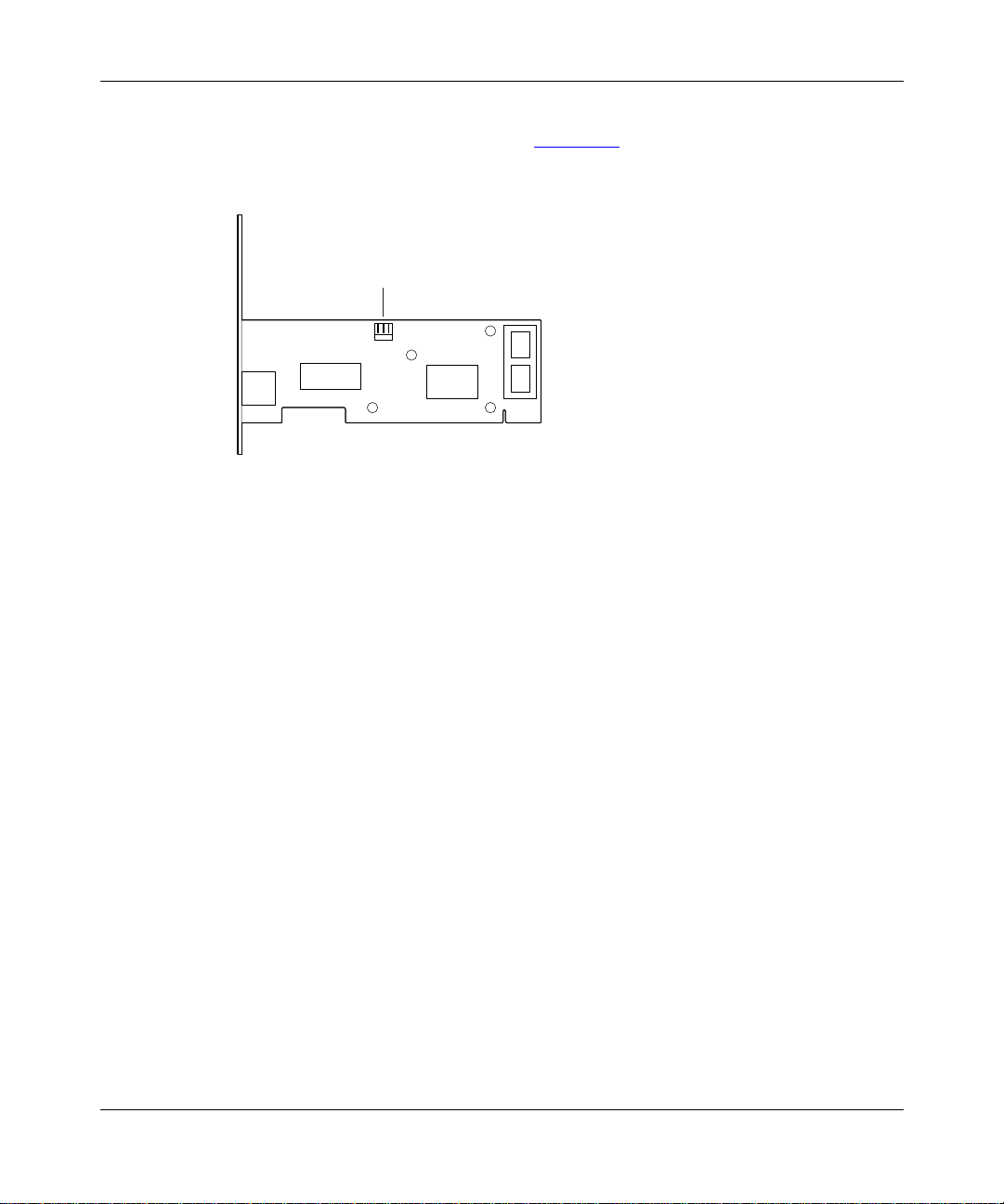
One end of the cable connects to the motherboard of your wor kstation. The other
end attaches to the WOL connector (Figure 1-3) on the board of the BayStack 21
network card.
WOL connector
Figure 1-3. WOL Connector
System Requirements
Introduction
9460EA
206379-A
Workstations using the BayStack 21 PCI 10/100 Adapter w/WOL must meet the
following r equirements:
• Microsoft Windo ws 95, Windows 98, or Windows NT
• PCI expansion slot with bus mastering capa bility
1-5
Page 24

Installation and Reference for the BayStack 21 PCI 10/100 Adapter w/WOL
Operating Environments
The BayStack 21 network card supports the operating systems and associated
drivers listed in Table 1-2.
Table 1-2. Supported Operatin g Systems
Driver Operating Systems
ODI Drivers • Novell NetWare 3.12, 4.1, 4.11
• Novell LAN Analyzer
NDIS 2.0 Drivers • Microsoft LAN Manager
• IBM LAN Server
• IBM LAN Support
•DEC PATHWORKS
NDIS 3.0 Drivers • Windows for Workgroups 3.11
•Windows 95
• Windows NT 3.51
NDIS 4.0 Drivers • Windows 95 OSR2, 98, NT 4.0
NDIS 5.0 Drivers • Windows 98
Packet Drivers • FTP PC/TCP
• NCSA TCP/IP
UNIX Drivers • SCO UNIX
•Linux
1-6
206379-A
Page 25

Cable Requirements
You can use Category 5 (Cat 5) Ethernet cables for 10 Mb/s and 100 Mb/s
network connections to the BayStack 21 network card.
Use the following guidelines when using Cat 5 cables:
• Maximum length between a workstation and a hub is 100 meters (m).
• Maximum length between two hubs is 10 m.
• M aximum le ngth betwee n tw o hubs which are func tioni ng as Ether net Cl ass 2
Repeaters is 1 00 m.
• Maximum total length between two workstations is 205 m.
Fast Etherne t C ab l es (100 Mb/s)
You must use a Cat 5 st raight-t hrough ca ble wit h one R J-45 c onnector on each end
for 100 Mb/s Ethernet connections. Do not use a crossover cable.
Ethernet Cables (10 Mb/s)
Introduction
206379-A
You can use Cat 3, Cat 4, or Cat 5 unshielded twisted pair (UTP) cable or an
EIA/TIA-568 100 ohm shielded twist ed pair (STP) cable for 10 Mb/s Ethernet
connections. You must use a straight through cable with one RJ-45 connec tor on
each end. Do not use a crossover cable.
1-7
Page 26

Page 27

This chapter describes how to install the BayStack 21 PCI 10/100 Adapter w/
WOL in an end-user workstation such as a desktop computer or server.
P ackage Contents
The BayStack 21 network card package contains the following:
• BayStack 21 PCI 10/100 Adapter w/WOL with one RJ-45 port
Chapter 2
Hardware Installation
206379-A
• WOL cable
• BayStack 21 PCI 10/100 Adapter w/WOL Software & Documentation CD,
including technic al documentation in PDF format
• Safety card
• Warranty/Registration card
Caution:
prior to handling the networ k card.
Touch a grounded metal object to free yourself of static electricity
2-1
Page 28

Installation and Reference for the BayStack 21 PCI 10/100 Adapter w/WOL
y
Installing the
To install the BayStack 21 network card in a workstation:
1.
2.
3.
4.
5.
6.
7.
8.
9.
10.
11.
Stack 21 PCI 10/100 Adapter w/ WOL
Ba
Shut down the workstation.
Unplug the workstation power cord from the power source.
Remove the chassis co ver of the workstation.
Locate an available PCI bus master expans ion slot in the workstation.
Remove the protective bracket from the slot.
Insert the contact edge of the BayStack 21 network card into the slot.
Make sure all edge connectors of the network card are firmly seated in
the slot.
Install and secure the bracket screw to secure the network card to the
chassis.
If you plan to install t he WOL cable, proceed to “Connecting the WOL
Cable” on page 2-3. Otherwise, contin ue with steps 10 thro ug h 12 .
Replace the chassis.
Install a standard Ethernet cable to the BayStack 21 network card
.
2-2
Plug one end of the network cable into the RJ-45 connector of the
a.
network card.
Plug the other end of the network cable into an RJ-45 port on the
b.
network device.
Reconnect the power cord and turn the workstation on.
12.
If the Basic Input/Output Sys tem (BIOS) section of your workstation
Note:
boot program is “Plug and Play” compliant, the BIOS will automatically
configure a newly installed network card.
If the BIOS program has assigned your network card an interrupt number that
is already assigned to another device, both devices will fault. If you detect this
problem, you must run the CMOS Setup Utility to manually assign a
nonconflicting inte rrupt number.
206379-A
Page 29

Connecting the WOL Cable
To install the WOL cable between the BayStack 21 networ k card and the chassis:
Make sure that the work sta ti on is di s connected from the power source
1.
and the chassis cover has been re moved.
Connect one end of the WOL cable to the network card WOL connector.
2.
You can use either connector on the WOL cable; they are identical. Refer to
Figure 1-3 on page 1-5
card.
Identify the WOL connector location on the workstation motherboard.
3.
The location of the connector is system dependent. You may see “WOL”
written on the motherboard.
Connect the other end of the WOL cable to the motherboard.
4.
Hardware Installation
for the location of the WOL connector on the network
Caution:
If the WOL connector on the motherboa rd does not f it the connector
on the WOL cable, or if the WOL con n ecto r doe s no t have three pi ns, do not
force the connec tion or alt er th e componen ts. Using a n incorrect connector can
damage the workstation.
Replace the chassis.
5.
Install a standard Ethernet cable to the BayStack 21 network card.
6.
Plug one end of the network cable into the RJ-45 connector of the
a.
network card.
Plug the other end of the network cable into a port on the network
b.
hub.
Reconnect the power cord and turn the workstation on.
7.
Press the Delete key to enter the BIOS CMOS Setup.
8.
Enable the WOL fu nct ion or the power-on function of the worksta tio n .
9.
The name of this function is architecture dependent. The function may be
located in a categor y heading such as “Power Management.”
Test the WOL functi on from the workstation you just conn ected or from
10.
another remote workstation that has a network card installed.
206379-A
2-3
Page 30

Page 31

Chapter 3
Software Installation
This chapter provide s instructions for installing the Windows- and Novell
NetWare-based BayStack 21 network driver software and configuring the
BayStack 21 PCI 10/100 Adapter w/WOL on your network. This chapter
describes procedures for Windows 95, Windows 98, Windows NT, and Novell
NetWare 4.x. Drivers for othe r oper ating system s ar e available bu t no t disc ussed i n
this guide. You can access information for install ing other drivers from the
BayStack 21 PCI 10/100 Adapter w/WOL Software & Documentation CD.
Different versions of Windo ws may have different installation screens than those
shown in these ins tructions. Your installation scre ens may appear in a different
order than the screens in this chapter, or you may encounter more or fewer
screens. You will be prompted for the same infor mation, regardless of the
Wind ows version.
206379-A
The driv er starts automatica lly for Windo ws 95 and W indows 98. Nor tel Networks
recommends using the automati c process to take advantage of this
“plug-and-play” capability. The driver must be manually conf igur ed for
Windows NT.
3-1
Page 32

Installation and Reference for the BayStack 21 PCI 10/100 Adapter w/WOL
Preinstallation
Perform the following tasks prior to installing the BayStack 21 network driver:
• You must install the BayStack 21 networ k card before installing the BayStack
21 network driver.
• You must have the Windows 95 or Windows 98 CD and the BayStack 21
network driver CD ready to use during the inst allation. You may be prompted
to install either CD. You may receive the “Ins ert Disk” and the “Please insert
the disk labeled Windows...” messages. If you get these messages, insert the
appropriate C D, e nter the appropriate drive letter a nd CD name, and click OK
to continue the installation. For example, if drive D is your CD drive and you
insert the Windows 95 CD, enter d:\win95 when prompted.
Installing the Network Driver in a Windows 95 Environment
This section describes the steps required to install the BayStack 21 network dr iver
in a Windows 95 workstation. Be sure you have performed the tasks in
“Preinstalla tion” on page 3-2 before continuing.
3-2
To install the network driver:
Turn on the power to the workstation, and start Windows 95.
1.
The New Hardware Found window opens, identi fying a gener ic netw ork card.
For instance, the window may list “PCI Ethernet Controller” (Figure 3-1
New Hardware Found
PCI Ethernet Controller
Select which driver you want to install for your new hardware:
Figure 3-1. New Hardware Found Window—Gen eri c
9562DA
).
206379-A
Page 33

Select which driver you want to install for your new hardware:
Software Install a tion
A second New Hardwa re Foun d window ope ns, iden tifying your BayStack 21
PCI 10/100 Adapter w/WOL (Figure 3-2).
New Hardware Found
BayStack 21 10/100 PCI Ethernet PCI Adapter
9563DA
Figure 3-2. New Hard ware Found Window—BayStack 21
Network Card
The Building Driver Informati on Database window opens. You do not have to
perform any tasks.
A generic Update Device Driver Wizard dialog box opens (Figure 3-3
Figure 3-3. Update Device Driver Wizard Dialog Box—Generic
).
206379-A
3-3
Page 34

Installation and Reference for the BayStack 21 PCI 10/100 Adapter w/WOL
Insert the
2.
Documentation
Click Next.
3.
The next Update Device Driver Wizard dialog box (Figure 3-4
BayStack 21 PCI 10/100 Adapter w/WOL Software &
CD into the CD drive
.
) indicates
that the new BayStack 21 network card has been found and the driver is
automatically loa ded.
Update Device Driver Wizard
Windows found the following updated driver for this
device:
BayStack 21 10/100 PCI Ethernet PCI Adapter
If you want to use this driver, click Finish. If this is not the
correct driver and you want to search for a different driver
manually, click Other Locations.
Location of Driver
Other Locations...
< Back
Finish Cancel
3-4
8527DB
Figure 3-4. Update Device Driver Wizard Dialog Box—BayStack 21
Network Card
206379-A
Page 35

Software Install a tion
Click Finish.
4.
The Copying Files dialog box opens (Figure 3-5
Copying Files...
The file NETB21ND.inf on Windows 95 CD-ROM
could not be found.
Insert Windows 95 CD-ROM into the drive
selected below, and click OK.
Copy files from:
D:\
).
OK
Cancel
Skip File
Details...
8528DB
Figure 3-5. Copying Files Dialog Box
Insert the
5.
Documentation
Enter the drive letter of the CD drive into the “Copy files from:” field.
6.
BayStack 21 PCI 10/100 Adapter w/WOL Software &
CD as indicated.
For example , if the CD dri ve in your workstation is drive D, enter
D:\
.
206379-A
Click OK.
7.
The Copying Files dialog box opens again.
Insert the Windows 95 CD as in dica te d.
8.
Enter D:\WIN95 into the “Copy files from” field.
9.
Click OK.
10.
The System Settings Change dialog box opens.
Remove any CDs from your CD drive.
11.
Click Yes.
12.
Restarting your system is necessary to enable your PC to finish setting up
your new hardw are.
3-5
Page 36

Installation and Reference for the BayStack 21 PCI 10/100 Adapter w/WOL
Configuring the Windows 95 Environment
You must configure the Windows 95 environment on your workstation after you
install the BayStack 21 network driver. Configure your workstation identification
first, and then configure TCP/IP properties.
Configuring the Workstation Identification
To configure the workstation identification :
From the Windows t askbar, choose Start > Settings > Control Panel.
1.
Double-click Network.
2.
The Network dialog box opens.The configuration tab is displayed by default.
Select the Ide nti ficatio n ta b (Figure 3-6).
3.
3-6
Figure 3-6. Network Dialog Box—Identification Tab
206379-A
Page 37

Software Install a tion
Enter the following information for your workstation:
4.
• Computer Name—The name assigned to your workstation by your
system administrat or
• Workgroup—Typically, the location or group name assigned by your
system administrat or
• Computer Description—The manufacturing description; usually appears
by default
Click OK.
5.
Files automatically copy. The Copying Files dialog box opens.
Enter the location of the requested files or CD in the “Copy files from:”
6.
field.
Click OK.
7.
The System Settings Change dialog box opens (Figure 3-7
Figure 3-7. System Settings Change Dialog Box
).
Restarting your system is necessary to enable your PC to finish setting up
your new hardw are .
Remove any CDs from your CD drive.
8.
Click Yes.
9.
Your system will restart.
206379-A
3-7
Page 38

Installation and Reference for the BayStack 21 PCI 10/100 Adapter w/WOL
Configuring the Network Properties
To configure the network properties of your workstation, such as TCP/IP
protocols:
From the Windows t askbar, choose Start > Settings > Control Panel.
1.
Click Network.
2.
The Network dialog box opens. The configuration tab (Figure 3-8
displayed by default.
) is
3-8
Figure 3-8. Network Dialog Box—Configuration Tab
206379-A
Page 39

Software Install a tion
Click Add.
3.
The Select Network Component Type dialog box opens (Figure 3-9
Figure 3-9. Select Network Component Type Dialog Box
Select Protocol.
4.
Click Add.
5.
The Select Network Protocol dialog box opens (Figure 3-10
).
).
206379-A
Figure 3-10. Select Network Protocol Dialog Box
3-9
Page 40

Installation and Reference for the BayStack 21 PCI 10/100 Adapter w/WOL
In the Manufacturers list , select Microsoft.
6.
In the Network Protocols list, select TCP/IP.
7.
Click OK.
8.
Return to the Con figurati o n tab.
9.
Select Nortel Ba yStack 21 10/100 PCI Ethernet Adapter (Figure 3-11).
10.
3-10
Figure 3-11. Configuration Tab, BayStack 21 Network Card Selected
206379-A
Page 41

Software Install a tion
Click Properti es .
11.
The TCP/IP Properties dialog box ope ns (Figur e 3-12
).
206379-A
Figure 3-12. TCP/IP Properties Dialog Box
Select the IP Address tab.
12.
If the workstation has a static IP address, specify the IP address, subnet
13.
mask, and default gateway of your workstation.
You can also choose the “Obtain an IP address automatically” option if the
workstation does not have a static IP address. If you choose this option, your
IP address will be supplied by a DHCP server.
3-11
Page 42

Installation and Reference for the BayStack 21 PCI 10/100 Adapter w/WOL
Use the Gateway or DNS Configuration tabs to configure other
14.
parameters, as needed.
Click OK.
15.
The Copying Files dialog box opens .
In the “Copy files from:” field, enter the location of the requested files or
16.
CD.
Click OK.
17.
The system restart dialog box opens. Restarting your system is necessary to
enable your PC to finish se tting up your new hardware.
Remove all CDs fr om the CD driv e.
18.
Click Yes.
19.
Your system restarts.
Installing the Network Driver in a Windows 98 Environment
This section describes the steps required to install the BayStack 21 network dr iver
in a Windows 98 workstation.
3-12
To install the network driver:
Turn on the power to the workstation, and start Windows 98.
1.
The New Hardware Found window opens, identi fying a gener ic netw ork card.
For instance, the window may list “PCI Ethernet Controller” (Figure 3-13
New Hardware Found
PCI Ethernet Controller
Select which driver you want to install for your new hardware:
Figure 3-13. New Hardware Found W i ndow—Generic
9562DA
).
206379-A
Page 43

Software Install a tion
A second New Hardwa re Foun d window ope ns, iden tifying your BayStack 21
PCI 10/100 Adapter w/WOL (Figure 3-14).
New Hardware Found
BayStack 21 10/100 PCI Ethernet PCI Adapter
Select which driver you want to install for your new hardware:
9563DA
Figure 3-14. New Hardware Found W i ndow
The Copying Files dialog box opens (Figur e 3-15).
Copying Files...
The file NETB21ND.cat on Windows 98 CD-ROM
could not be found.
Insert Windows 98 CD-ROM into the drive
selected below, and click OK.
Copy files from:
D:\
Figure 3-15. Copying Files Dialog Box
Insert the required C D int o th e CD dr ive of your worksta t ion .
2.
Enter the location and file name of the CD in the “Copy files from:” field.
3.
OK
Cancel
Skip File
Details...
8528DC
206379-A
For instance, enter
D:\nt_9x
if you inserted the Windows 98 CD into drive D.
3-13
Page 44

Installation and Reference for the BayStack 21 PCI 10/100 Adapter w/WOL
Click OK.
4.
The Copying Files dialog box opens (Figure 3-16
Figure 3-16. Copying Files Dialog Box
Insert the required C D int o th e CD dr ive of your worksta t ion .
5.
Enter the location and file name of the CD in the “Copy files from:” field.
6.
Click OK.
7.
).
The install program searc hes the CD. The New Hardware Found dialog box
opens (Figure 3-17
).
3-14
Figure 3-17. New Hardware Found D ial og B ox
206379-A
Page 45

Software Install a tion
Select one of the following options:
8.
• Driver from disk provided by hardware manufact urer (recommended by
Nortel Networks)
• Do not install a driver (Windows will not prompt you again)
• Select from a list of alternate drivers
Click OK.
9.
The System Settings Change dialog box opens (Figure 3-18
Figure 3-18. System Settings Change Dialog Box
).
Restarting your system is necessary to enable your PC to finish setting up
your new hardw are .
Remove all CDs fr om the CD driv e.
10.
Click Yes.
11.
Your system restarts.
206379-A
3-15
Page 46

Installation and Reference for the BayStack 21 PCI 10/100 Adapter w/WOL
Configuring the Windows 98 Environment
You must configure the Windows 98 environment on your workstation after you
install the BayStack 21 network driver.
Configuring the Network Properties
To configure the network properties for your workstation:
From the Windows t askbar, choose Start > Settings > Control Panel.
1.
Double-click Network.
2.
The Network dialog box opens. The TCP/IP network protocol for the
BayStack 21 network driver is already installed.
The configur ation tab (Figure 3-19
) is displayed by default.
3-16
Figure 3-19. Network Dialog Box—Configuration Tab
Select Nortel Ba yStack 21 10/100 PCI Ethernet Adapter.
3.
206379-A
Page 47

Software Install a tion
Click Properti es .
4.
The TCP/IP Properties dialog box ope ns (Figur e 3-20
).
206379-A
Figure 3-20. TCP/IP Properties Dialog Box
Select the IP Address tab.
5.
If the workstation has a static IP address, specify the IP address, subnet
6.
mask, and default gateway of your workstation.
You can also choose the “Obtain an IP address automatically” option if the
workstation does not have a static IP address. If you choose this option, your
IP address will be supplied by a DHCP server.
Use the Gateway or DNS Configuration tabs to configure other
7.
parameters, as needed.
Click OK.
8.
The System Settings Change dialog box opens.
3-17
Page 48

Installation and Reference for the BayStack 21 PCI 10/100 Adapter w/WOL
Click Yes.
9.
Your system restarts.
Installing the Network Driver in a Windows NT Environment
The Windows NT installation of the BayStack 21 net work driver i s not automatic.
You must install the driver manually.
To install the network driver:
From the Windows t askbar, choose Start > Settings > Control Panel.
1.
Double-click Network.
2.
The Network dialog box opens. The Identification tab is displayed by default.
Select the Adapters tab (Figure 3-21).
3.
3-18
Figure 3-21. Network Dialog Box—Adapters Tab
206379-A
Page 49

Software Install a tion
Select Add .
4.
The Select Network Adapter dialog box opens (Figure 3-22
Figure 3-22. Select Network Adapter Dialog Box
Click Have Disk.
5.
).
206379-A
Insert the
6.
Documentation
Specify the letter o f the dr ive into w hi ch you insta lled the C D.
7.
BayStack 21 PCI 10/100 Adapter w/WOL Software &
CD into the CD drive.
Typically the CD drive is letter D.
3-19
Page 50

Installation and Reference for the BayStack 21 PCI 10/100 Adapter w/WOL
Click OK.
8.
The Select OEM Option dialog box opens (Figure 3-23
Figure 3-23. Select OEM Option Dialog Box
Select Nortel Ba yStack 21 10/100 PCI Ethernet Adapter
9.
Click OK.
10.
The Speed/Duplex Mo de dialog box ( Figu re 3-24
) opens. The default mode is
Auto.
).
.
3-20
Figure 3-24. Speed/Duplex Mode Dialog Box
Select Auto.
11.
Click OK.
12.
206379-A
Page 51

Configuring the Network Properties
To configure the network properties for your workstation:
From the Windows t askbar, choose Start > Settings > Control Panel.
1.
Double-click Network.
2.
The Network dialog box opens. The Identification tab is displayed by default.
Click the Protocols tab.
3.
Software Install a tion
The Protocols tab (Figure 3-25
) is displayed.
206379-A
Figure 3-25. Network Dialog Box—Protocols Ta b
3-21
Page 52

Installation and Reference for the BayStack 21 PCI 10/100 Adapter w/WOL
Click Properti es .
4.
The Microsoft TCP/IP Propertie s dialog box opens (Figure 3-26
).
3-22
Figure 3-26. Microsoft TCP/IP Properties Dialog Box
If the workstation has a static IP address, specify the IP address, subnet
5.
mask, and default gateway of your workstation.
You can also choose the “Obtain an IP address from a DHCP server” option if
the workstation does not have a static IP address.
Use the DNS tab to add additional network parameters, if needed.
6.
Click OK.
7.
206379-A
Page 53

Software Install a tion
Click Close.
8.
The System Settings Change dialog box opens. Restarting your system is
necessary to enable your PC to finish setting up your new hardware.
Click Yes.
9.
Your system restarts.
Installing the Net work Driver in a Novell NetWare 4.x Environment
This section describes the steps required to install the BayStack 21 network dr iver
software in a Novell NetWa re version 4.x environment. You must install and
configure the software on your Novell server and client.
If you are install ing the BayStack 21 ne twork dr i ve r software in a Novell NetWare
version 3.12 environment, refer to the Readme.txt file on the BayStack 21 PCI 10/
100 Adapter w/WOL Software & Documentation CD.
Installing the Network Driver in a Novell NetWare Server
To install the BayStack 21 network driver in a Novell NetWare server:
Verify that your Novell NetWare server includes the fol lowing files:
1.
• \NETWARE\SER VER\4.X\MSM.NLM (Media Support Module)
• \NETWARE\SERVER\ETHERTSM.NLM (Topology Specific Module for
Ethernet)
Change to the Novell NetWare server directory.
2.
For instance, type the command:
CD\NWSERVER
Type:
3.
SERVER
Press Enter.
4.
At the server prompt, enter:
5.
LOAD INSTALL
From the Installation Options menu, select Driver options.
6.
206379-A
3-23
Page 54

Installation and Reference for the BayStack 21 PCI 10/100 Adapter w/WOL
Press Enter.
7.
From the Driver Optio ns m en u, s elect Configure network drivers.
8.
Press Enter.
9.
From the Additional Driver Actions menu, select Select a driver.
10.
Press Enter.
11.
Press Insert to install an unlisted driver.
12.
By default, your a: drive is scanned.
Press <F3> to specify another path or drive.
13.
Insert the
14.
Documentation
Press Enter.
15.
BayStack 21 PCI 10/100 Adapter w/WOL Software &
CD into the CD drive of your server.
The following file automatically copies from the BayStack 21 PCI 10/100
Adapter w/WOL Software & Documentation CD to your Novell NetWare
server:
• \NETWARE\SERVER\B21LAN10.LAN
From the Select a driver to install: menu, select Nortel 21 10/100 PCI
16.
Ethernet Driver.
Press Enter.
17.
The “Do you want to copy driver B21LAN10.LAN (Y)(N)” message is
displayed.
Select Yes.
18.
Proceed to the next section if you want to specify driver parameters.
19.
Specifying Driver Parameters
The BayStack 21 network driver installs with default pa rameters. You can set
specific driver parameters for the server.
3-24
206379-A
Page 55

Software Install a tion
To set specific driver parameters:
From the Board B21LAN10_ 1 (Driver B21LAN10) Actions menu, select
1.
“Select/Modify driver parameters and protocols.”
Press Enter.
2.
The default protoc ol is IPX. You can also select TCP/IP or AppleTalk.
Select a protocol from the available options.
3.
Specify the slot number (slot #).
4.
Select “Save parameter and load select driver.”
5.
If you select the IPX protocol, the network number (network #) is randomly
generated.
Press Enter at each of the following four prompts :
6.
• 802.3
• 802.2
•SNAP
206379-A
• Ethernet II
3-25
Page 56

Installation and Reference for the BayStack 21 PCI 10/100 Adapter w/WOL
Installing the Network Card in a Novell NetWare Client
To install the BayStack 21 network driver in your Novell NetWare client:
Verify that your BaySta c k 21 network card is proper ly in sta l led in your
1.
Novell NetWare workstation.
Insert the
2.
BayStack 21 Network Driver CD
into the CD drive in your
workstation.
Access the Novell NetWare client directory.
3.
Copy the following command to the client directory:
4.
\NETWARE\DOSODI\B21ODI10.COM
Enter the following commands, in order:
5.
lsl
b21odi10
ipxodi
netx
Press Enter.
6.
(or
vlm
)
You can now log in to your network.
Edit the
7.
Verify that there is a protocol binding for Ethernet 802.3 in the
8.
NET.CFG
file to change driver parameters.
file.
Refer toAppendix B, “Novell NetWare Reference Info rma tio n
NET.C FG files.
NET.CFG
” for sample
3-26
206379-A
Page 57

You can use the Wake On LAN (WOL) feature to start up remot e workstations
without end-user inter vention. A BayStack 21 PCI 10/100 Adapter w/WOL must
be installed on each workstation that you want to start remotely. You must set up
each workstation prior to using the WOL feature.
Setting Up the Workstation
Perform the follo wing tasks prior to using the WOL feature on a remote
workstation :
Chapter 4
Using the WOL Feature
206379-A
• Make sure the WOL connector is attached to the BayStack 21 network card
and to the motherboard of the works tat ion.
Refer to “Connecting the WOL Cable
• Place the workstation in sleep (or standby) mode, or turn the workstation off
completely.
” on page 2-3 for instructions.
4-1
Page 58

Installation and Reference for the BayStack 21 PCI 10/100 Adapter w/WOL
Running the WOL Feature
You must have a WOL-capable utility on the worksta tion from which you are
using the WOL feature to turn on remote workstations. There are several
commercially available utilities. As an example, instructions for using the AMD
Magic Packet Utility are provided in this section. You can obtain this utility from
www.amd.com. Procedures for utilities from other companies vary.
To use the WOL feature:
Open a WOL utility, such as the Magic Packet Utility (Figure 4-1).
1.
Figure 4-1. Magic Packet Utility Window
4-2
From the Magic Packet Utility menu, select Magic Packets > Create a
2.
List of H o sts.
The Create a List of Hosts on LAN dialog box opens (Figure 4-2
Figure 4-2. Create a List of Hosts on LAN Dialog Box
).
206379-A
Page 59

Using the WOL Feature
Enter the subnet mask of the remote workstation you want to turn on.
3.
The utility maps, or locates, BayStack 21 network cards in the subnet you
specifie d. Make sure the remote worksta ti on is still tur ned on. It should not be
in standby or shutdown mode.
Click OK.
4.
The Magic Packet Util ity identification windo w opens (Figure 4-3
Figure 4-3. Magic Packet Utility Identification W indow
Click OK.
5.
The NewGroup window opens (Figure 4-4
), displaying information about the
remote workstati on you want to turn on.
).
206379-A
Figure 4-4. NewGroup Window
You can now turn on the remote workstation. Continue with the se instr uctions
when the workstation is in standby or shutdown mode.
4-3
Page 60

Installation and Reference for the BayStack 21 PCI 10/100 Adapter w/WOL
Return to the Magic Packet Utility menu.
6.
Select Magic Packet > Power on One Host.
7.
The Send a Magic Packet to One Host dialog box opens (Figur e 4-5
Figure 4-5. Send a Magic Packet to One Hos t Dialog Box
Enter the physical address of the remote workstation you want to turn on.
8.
Do not enter the IP address.
Click Send.
9.
The utility sends a packe t to the BaySta ck 21 network card on the remote
workstation to turn on the workstation.
).
4-4
Click Close.
10.
206379-A
Page 61

This chapter provides seve ral methods for trouble shooting problems related to the
BayStack 21 PCI 10/100 Adapter w/WOL.
Diagnostic LEDs
Three LEDs on the front of the BayStack 21 network card provide diagnostic
information. The 10 Mb/s and 100 Mb/s Link LEDs indicate successful network
connections to Etherne t and Fast Ethernet devices, respec tively. The Link LEDs
remain steady if the connection is stable. You should check the RJ-45 connection
if the LED is not steady. The Activity LED indicates active n e t wo r k traffic.
Chapter 5
Troubleshooting
Table 5-1
Table 5-1. LED Indica tio ns
Label Color Activity Description
10 LNK Green On A 10 Mb/s connection has been est ablished.
100 LNK Green On A 100 Mb/s connection has been established.
ACT Green On Heavy network traffic is passing through the port.
206379-A
describes the Link and Activity LED indications.
Off Power is not supplied to the network card, or a 10 Mb/s
connection is not established.
Off Power is not supplied to the network card, or a 100 Mb/s
connection is not established.
Blinking Intermittent or light network traffic is passing through the port.
The rate of blinking is proportional to the amount of network
traffic.
5-1
Page 62

Installation and Reference for the BayStack 21 PCI 10/100 Adapter w/WOL
Hardware Issues
Perform the following tasks to check for hardware problems:
• Verify that you are using the correct cables and the correct cable lengths, as
described in “Cable Requirements” on page 1-7
• Make sure the network cable is firmly connected to the network card and to a
network device.
• Connect the Ethernet cable to a different port on the network device.
• Verify that the BayStack 21 network card is fully and firmly seated in the slot
connector in the workstation chassis. Check the connector edges of the card
for damage.
• Replace the network card in question with a network card that you are sure
functions properly. Run generic network interface card diagnostic tests.
• Install the network card in ques tion into another workstation and run the te sts
again.
• Remove all other network cards from the workstation and run the tests again.
If the verification/diagnostic run is not normal, there is probably an interrupt
number conflict. You must manually resolve the conflict by running a CMOS
Setup utility after you have reinstalled the expansion cards.
.
Software Issues
Perform the following tasks to check for software problems:
• Verify that the prop er driver is loaded, as explaine d in Chapter 3, “
Installation. ” Be s ure y ou foll o wed the dir ections f or t he ope rating sy ste m you
are running on the workstation.
• Check that the new configurat ions match the configurations of the network
device if you have manually configured the speed or mode of the network
card. Nortel Networks recommends setting the network card to
autonegoti ation when installing the network driver.
5-2
Software
206379-A
Page 63

Troubleshooting
• Verify that the PCI slot in the workstation is an enabled bus-master slot.
Do not use a slave PCI slot for the BayStack 21 network card. Some
computers may require that you configure the PCI slot to enable bus
mastering. Refer to your compute r manual for information about the PCI
BIOS setup program.
Be sure that the slot is configured for level-triggered interrupts. It should not
be configured f or edge-triggered interrupts. Table 5-2
describes typical PCI
parameter configurations. Parameters may vary in different systems.
Table 5-2. Typical PCI Slot Parameters
Parameter Configuration
PCI Slot # Slot number where the network card is installed
Master Enabled
Slave Enabled
Latency Timer 40 (range: 20 to 255)
Interrupt Type Level-triggered
Interrupt Number Choice of any number that the BIOS setup program
supplies. (The interrupt number should not conflict
with other instal led cards.)
206379-A
• Verify that your BIOS software correctly supports the PCI Local Bus
Specifi cation, version 2.0 or later. Upgrade your BIOS software if needed.
• Determine whether or not the network card slot is deactivated at the BIOS
leve l. Use the CMOS Setup utili ty i n your w orksta tion to pro vide t he option to
activate or deactivate slots.
• Disable the Plug and Play option (PnP) in the BIOS setup program, if your
computer does not requir e this op tion. In correctly assigned resources between
network cards may cause a problem.
Note:
Always consult your computer manual for information about changing
motherboard jumper and BIOS settings. If you modify the BIOS settings,
make sure the jumper and BIOS settings match.
• You may need to reserve interrupts and memory addresses for installed
Industry Standard Arch itecture (ISA) cards to prevent PCI cards from using
the same settings. Refer to your PC manual for instr uctions.
5-3
Page 64

Page 65

Tables in this appendix provide technical product specifica tions and list the
ava ilable software drivers for the BayStack 21 PCI 10/100 Adapter w/WOL.
Product Specifications
Table A-1 lists technical specifications for the BayStack 21 network card.
Table A-1. Technical Spec ifications
Appendix A
Technical Specifications
206379-A
Standards Compatibility
EMC Compliance
CE Mark: EN50081-1
Emissions: FCC Class B
Physical Dimensions
Network Card: 120 x 53.5 mm (4.72 x 2.11 in)
WOL Cable: 298 mm (11.75 in) (not including connectors)
Weight
IEEE 802.3 10BASE-T
IEEE 802.3u 100BASE-TX
PCI bus V2.2
ACPI
OnNow/PC98
EN55022
IEC1000-4-2/3/4/6
VCCI Class B
Industry Canada Class B
EN55022 (CISPR 22) Class B
55g (1.94 oz)
A-1
Page 66

Installation and Reference for the BayStack 21 PCI 10/100 Adapter w/WOL
Table A-1. Technical Specifications (continued)
Environment
°
Operating: 0
Humidity: 5% to 95%, noncondensing
Power Consumption
Network Interface
10BASE-T: RJ-45 (UTP Cable, Categories 3, 4, 5)
100BASE-TX: RJ-45 (UTP Cable, Category 5)
Data Interface
I/O Address
Interrupt
LED Indicators
to 50° C (32° to 122° F)
+5 V DC at 145mA (Standby)
+5 V DC at 300mA (Transmit)
32-bit bus- ma stering PCI
Automat ically determined by configuration space
INT A, mapping to BIOS IRQ setup
10 Mb/s, 100 Mb/s, Activity
Software Drivers
Table A-2 lists the available software drivers for the BayStack 21 PCI 10/100
Adapter w/WOL. Refer to Chapter 3, “Software Installation,” for installation
instructions regarding the Windows-based drivers. Refer to the README files
associated with other drivers for installation instructions.
A-2
Table A-2. Available Software Drivers
Driver Compatible Opera ting Systems
Microsoft Windows 95/Wind ows 98
Windows NT 3.51, 4.0
Windows for Workgroups 3.11
LAN Manager 2.x
Novell NetWare NetWare 3.1x , 4.x
32-bit ODI driver
16-bit DOS ODI driver
Client32 for Windows 95
SCO UNIX 3.2.4
ODT 5.0
Other NDIS2 DOS Mode Driver
Packet Dr ive r
206379-A
Page 67

Appendix B
Novell NetWare Reference Information
This appendix provides reference files and information for your Novell
NetWare 4.x operating system. Server and client information is provided in the
following se ctions.
If you are installing the BaySt ack 21 PCI Networ k Driver software in a Novell
NetW are ve rsion 3.12 en vironment , refer to the Readme.txt f il e on th e BayStac k 21
PCI 10/100 Adapter w/WOL Software & Documentation CD.
Novel l NetWare Server
Parameters
This section provides information about the Novell NetWare 4.x
AUTOEXEC.NCF files and parameters.
Sample
Sample files are provided for workstations that have one or two network cards
installed.
AU TOEXEC.NCF
AUTOEXEC.NCF
Files
Files and
206379-A
B-1
Page 68

Installation and Reference for the BayStack 21 PCI 10/100 Adapter w/WOL
One Network Card Installed
The following files are typically part of the AUTOEXEC.NCF file, with one
network card installed in the workstation:
LOAD C:B21LAN10 FRAME=ETHERNET_802.2 NAME=E_8022
LOAD C:B21LAN10 FRAME=ETHERNET_802.3 NAME=E_8023
LOAD C:B21LAN10 FRAME=ETHERNET_II NAME=E_II
LOAD C:B21LAN10 FRAME=ETHERNET_SNAP NAME=E_SNAP
BIND IPX E_8022 NET=10
BIND IPX E_8023 NET=20
BIND IPX E_II NET=30
BIND IPX E_SNAP NET=40
Two Network Cards Installed
The following files are typically part of the AUTOEXEC. NCF file, with two
network cards installed in the workstation:
LOAD C:B21LAN10 PCI_SLOT=3 FRAME=ETHERNE T_80 2.2 NAME=E_8022_1
LOAD C:B21LAN10 PCI_SLOT=3 FRAME=ETHERNE T_80 2.3 NAME=E_8023_1
LOAD C:B21LAN10 PCI_SLOT=3 FRAME=ETHERNET_II NAME=E_II_1
LOAD C:B21LAN10 PCI_SLOT=3 FRAME=ETHERNET_SNAP NAME=E_SNAP_1
LOAD C:B21LAN10 PCI_SLOT=4 FRAME=ETHERNE T_80 2.2 NAME=E_8022_2
LOAD C:B21LAN10 PCI_SLOT=4 FRAME=ETHERNE T_80 2.3 NAME=E_8023_2
LOAD C:B21LAN10 PCI_SLOT=4 FRAME=ETHERNET_II NAME=E_II_2
LOAD C:B21LAN10 PCI_SLOT=4 FRAME=ETHERNET_SNAP NAME=E_SNAP_2
B-2
BIND IPX E_8022_1 NET=10
BIND IPX E_8023_1 NET=20
BIND IPX E_II_1 NET=30
BIND IPX E_SNAP_1 NET=40
BIND IPX E_8022_2 NET=10
BIND IPX E_8023_2 NET=20
BIND IPX E_II_2 NET=30
BIND IPX E_SNAP_2 NET=40
206379-A
Page 69

Novell NetWare Reference Information
Sample
AUTOEXEC.NCF
File Parameter s
This section describes the AUTOEXEC.NCF file parameters SLOT, FRAME,
NODE, and Medium.
SLOT Parameter
The SLOT parameter specifies which adapter is enabled when multiple BayStack
21 PCI Network Cards are inst alled in your worksta tio n. The SLO T k eyw ord is an
index value corresponding to PCI BIOS. The mapping from the SLOT parameter
to the physical PCI slot is different from one workstation to another.
The following are examp les of typical SLOT parameters:
LOAD C:B21LAN10 SLOT=3 FRAME=ETHERNET _802. 2
LOAD C:B21LAN10 SLOT=4 FRAME=ETHERNET_II
FRAME Parameter
The FRAME parameter specif ies which type of frame is used by the BayStack 21
network driver.
Accepted value s include:
• Ethernet_802.3
206379-A
• Ethernet_802.2
• Ethernet_II
• Ethernet_SNAP
Multiple frame types can be enabled by loading the same driver with different
FRAME type parameters.
The following are examp les of typical SLOT parameters:
LOAD C:B21LAN10 FRAME=ETHERNET_802.2
LOAD C:B21LAN10 FRAME=ETHERNET_802.3
LOAD C:B21LAN10 FRAME=ETHERNET_II
LOAD C:B21LAN10 FRAME=ETHERNET_SNAP
B-3
Page 70

Installation and Reference for the BayStack 21 PCI 10/100 Adapter w/WOL
NODE Parameter
You can use the NODE parameter to replace the default node address associated
with your electrically erasable programmable read-only memory (EEPROM).
The followi ng is an example of a typical NODE parameter:
LOAD B21LAN10 NODE=0000E8001122
Medium Parameter
The Medium parameter specif ies which medium type is used by the BayStack 21
network driver. The medium type ref ers to the transmission type.
Accepted value s include:
• AUTO (sense)
• 100FULL (duplex mode)
• 100HALF (duplex mode)
• 10FULL (duplex mode)
• 10HALF (duplex mode)
B-4
The followi ng is an example of a typical Medium parameter:
LOAD B21LAN10 SLOT=3 FRAME=ETHERNET _802. 2 Medium=100Full
206379-A
Page 71

Novell NetWare Reference Information
Novell NetWare Client Commands and
This section provides information about commands and the NET.CFG file.
Client Commands
Table B-1
BayStack 21 network driver into your Novell NetWare client.
Table B-1. Commands
Command Description
lsl Supports the OSI link support layer
b21odi10 Client driver copied from the
ipxodi Default protocol stack
netx (or vlm) Server connection
Sample
The MLDI section of the NET.CFG file is the section usually edited.
The following NET.CFG file is a sample:
briefly describes the commands you enter when installing the
BayStack 21 PCI 10/100 Adapter
w/WOL Software & Documentation
NET.CFG
Files
NET.CFG
CD
File
206379-A
Link Driver B21ODI10
FRAME Ethernet_802.2
FRAME Ethernet_802.3
FRAME Ethernet_II
FRAME Ethernet_SNAP
PROTOCOL IPX 0 Ethernet_802.3
.
.
MEDIUM AUTO ;operate on auto negotiation mode
; MEDIUM 10HALF ;operate on 10M/HalfDuplex mode
; MEDIUM 10FULL ;operate on 10M/Fullduplex mode
; MEDIUM 100HALF ;operate on 100M/HalfDuplex mode
; MEDIUM 100FULL ;operate on 100M/Fullduplex mode
B-5
Page 72

Page 73

Numbers
10 Mb/s Ethernet cables, 1-6
100 Mb/s Ethernet cables, 1-6
10BASE-T/100BASE- TX ports, 1-2
A
autonegotiation, 1-2
C
cables
10 Mb/s Ethernet, 1-6
100 Mb/s Ethernet, 1-6
requirements, 1-6
WOL, 1-4
connectors
10BASE-T/100BASE-TX, 1-2
RJ-4 5 po rt, 1-2
WOL, 1-4
conventions, text, xvii, xviii
customer support, xviii
E
Etherne t cables, 1-6
F
Fast Ethernet cables, 1-6
I
installation
network card, 2-2
network driver
in a Windows 95 system, 3-2
in a Windows 98 system, 3-12
in a Windows NT system, 3-18
preins tallation ta sks, 3-2
WOL cable, 2-3
IndexIndex
L
LEDs, 1-3, 5-1
N
network card
configuring
in a Windows 95 en vironment, 3-6
in a Windows 98 en vironment, 3-16
in a Windows NT environment, 3-21
installing, 2-2
network drivers
installing in a Novell NetWare 4.x environment,
3-23
installing in a Windows 95 environment, 3-2
installing in a Windows 98 environment, 3-12
installing in a Windows NT environment, 3-18
insta lli ng in other syst ems, A-2
network properties
configuring for Windows 95, 3-8
configuring for Windows 98, 3-16
configuring for Windows NT, 3-21
Novell Net Ware
client commands, B-5
client file examples, B-5
server file examples, B-1
specif ying driver parameters, 3-24
O
operating environments, 1-5
P
package contents, 2-1
ports
autonegotiation, 1-2
Ethernet 10BASE-T/100BASE-TX, 1-2
206379-A
Index-1
Page 74

product
components, 1-2
specifications, A-1
support, xviii
R
requirements, syst em, 1-5
S
support, Nortel Networks, xviii
system requirements, 1-5
T
technical publications, xviii
technical specifications, A-1
technical support, xviii
text conventions, xvii
troubleshooting
diagnostic LEDs, 5-1
hardware, 5-2
software, 5-2
W
Wake on LAN. See WOL , 1-1
Windows 95
network properties, 3-8
workstation identification, 3-6
Windows 98, network properties, 3-16
Windows NT, network properties, 3-21
WOL
running , 4-2
setting up the workstation, 4-1
using, 4-1
WOL cable
descri ption, 1-4
installation, 2-3
WOL connector, description, 1-4
worksta ti on identific at io n
configuring for Windows 95, 3-6
Index-2
206379-A
 Loading...