

Page 1

Part No. 208700-B
September 2001
4401 Great America Parkway
Santa Clara, CA 95054
Using the Business Policy Switch 2000 Version 1.2
Page 2

2
Copyright © 2001 Nortel Networks
All rights reserved. Printed in the USA. September 2001.
The information in this document is subject to change without not ice. The statements, configurations, technical
data, and recommendations in this document are believed to be accurate and reliable, but are presented without
express or implied warranty. Users must take full responsibility for their applications of any products specified in
this document. The information in this document is proprietary to Nortel Networks NA Inc.
Trademarks
Nortel Networks is a trademark of Nortel Net works.
Accelar, Autotopology, BaySecure, BayStack, Business Policy Switch 2000, Nortel Networks, the Nortel Networks
logo, Optivity, Optivity Policy Services, Passport, and StackProbe are trademarks of Nortel Networks.
Microsoft, Windows, Windows NT, and XP are registered trademarks of Microsoft Corporation.
Acrobat Reader and Adobe are registered t rademarks of Adobe Systems Incorporated.
Java is a registered trademark of Sun Micr osystems, Inc.
All other trademarks and registered trademarks are the property of their respective owners.
Statement of Conditions
In the interest of improving internal design, operational function, and/or reliability, Nortel Networks NA Inc.
reserves the right to make changes to the products described in this document without notice.
Nortel Networks NA Inc. does not assume any liability that may occur due to the use or application of the
product(s) or cir cuit l ay ou t(s ) de s cribed herein.
USA Requirements Only
Federal Communications Commission (FCC) Compliance Notice: Radio Frequency Notice
Note: This equipment has been tested and found to comply with the limits for a Class A digital device, pursuant to
Part 15 of the FCC rules. These limits are designed to provide reasonable protection against harmful interference
when the equipment is operat ed in a commercial environment. This equipment generates, use s, and can radiate
radio frequency energy. If it is not installed and used in ac cordance with the i nstruction manua l, it may cause
harmful interference to radio communications. Operation of this equipment in a residential area is likely to cause
harmful interference, in which case users will be required to take whatever measures may be necessary to correct
the interference at their own expense.
European Requirements Only
EN 55 022 Statement
This is to certify that the Nortel Networks Business Policy Switch 2000 is shielded against the generation of radio
interference in accordance with the application of Council Directive 89/336/EEC, Article 4a. Conformity is
declared by the application of EN 55 02 2 Class A (CISPR 22).
Warning: This is a Class A product. In a domestic environment, this product may cause radio interference, in
which case, the user may be required to t ake appropriate measures.
208700-B
Page 3

Achtung: Dieses ist ei n Gerät der Funkstörgrenzwer tklasse A. In Wohnbereichen können bei Betrieb dieses
Gerätes Rundfunkstörungen auftreten, in welchen Fällen der Benutzer für entsprechend e Gegenmaßnahmen
verantwortlich ist.
Attention: Ceci est un produit de Classe A. Dans un envi ronnement domesti que, ce produit risque de créer des
interférences radioélectriques, il appartiendra alors à l’utilisateur de prendre les mesures spécifiques appropriées.
EC Declaration of Conformity
This product conforms to the provisions of Council Directi ve 89/336/EEC and 73/23/EEC. The Declaration of
Conformity is avai lable on the Nortel Networ ks World Wide Web site at http://libra2.corpwest.baynetworks.com/
cgi-bin/ndCGI.exe/DocView/.
Japan/Nippon Requirements Only
Voluntary Control Council for Interference (VCCI) Statement
3
Taiwan Requirements
Bureau of Standards, Metrology and Inspection (BSMI) Statement
Canada Requirements Only
Canadian Department of Communications Radio Interference Regulations
This digital apparatus (Business Policy Switch 2000) does not exceed the Class A limits for radio-noise emissions
from digital apparatus as set out in the Radio Interference Regulations of the Canadian Department of
Communications.
Using the Business Policy Switch 2000 Version 1.2
Page 4

4
Règlement sur le brouillage radioélectrique du ministère des Communications
Cet appareil numérique (Business Policy Switch 2000) respecte les limites de bruits radioélectriques visant les
appareils numériques de classe A prescrites dans le Règlement sur le brouillage radioélectrique du ministère des
Communications du Canada.
208700-B
Page 5

Nortel Networks NA Inc. Software License Agreement
NOTICE: Please carefully read this license agreement before copying or u s in g the accompanying software or
installing the hardware unit with pre-enabled software (each of which is referred to as “Software” in this
Agreement). BY COPYING OR USING THE SOFTWARE, YOU ACCEPT ALL OF THE TERMS AND
CONDITIONS OF THIS LICENSE AGREEMENT. THE TERMS EXPRESSED IN THIS AGREEMENT ARE
THE ONLY TERMS UNDER WHICH NORTEL NETWORKS WILL PERMIT YOU TO USE THE
SOFTWARE. If you do not accept these terms and conditio ns, return the product, unused and in the original
shipping container, within 30 days of purchas e to obtain a credit for the full purchase price.
1. License Grant. Nortel Networks NA Inc. ( “Nortel Netwo r ks ”) grants the end user of the Software (“Licensee”)
a personal, nonexcl usive, nontransferable license: a) to use the Software either on a s ingle computer or, if
applicable, on a single authorized device identified by host ID, for which it was originally acquired; b) to copy the
Software solely for backup purposes in support of authorized use of the Software; and c) to use and copy the
associated user manual solely in suppo r t o f aut horized use of the Software by Licensee. This license applies to the
Software only and does not extend to Nortel Networks Agent software or other Nortel Networks software products.
Nortel Networks Agent software or other Nortel Networks software products are licensed for use under the terms of
the applicable Nortel Networks NA Inc. So ftware License Agreement that accompan ie s such software and upon
payment by the end user of the applicab l e license fees for such software.
2. Restrictions on use; reservation of rights. The Software and user manuals are protected under cop yri ght laws.
Nortel Networks and/or its lic ensors ret ain all title and ownership in bo th the S oft ware an d u s er m anuals, including
any revisions made by Nortel Networks or its licensors. The copyright notice must be reproduced and included with
any copy of any portion of the So ftware or user manuals. Licensee may not modify, translate, decompile,
disassemble, use for any competitive analysis, reverse engineer, distribute, or create derivative works from the
Software or user manuals or any copy, in whole or in part. Except as expressly provided in this Agreement,
Licensee may not copy or transfer the Software or user manuals, in whole or in part. The Software and user manuals
embody Nortel Networks’ and its licensors’ confidential and proprietary intellectual property. Licensee shall not
sublicense, assign, or otherwise disclose to any third party the Software, or any information about the operation,
design, performance, or implement ation of the Software and user manuals that i s confidential to Nortel Networks
and its licensors; however, Licensee may grant permission to its consultants, subcontractors, and agents to use the
Software at Licensee’s facility, provided they have agreed to use the Software only in accordance with the terms of
this license.
3. Limited warranty. Nortel Networks warrants each item of Software, as delivered by Nortel Networks and
properly installed and operated on Nortel Networks hardware or other equipment it is originally licensed for, to
function substantially as described in its accompanying user manual during its warranty period, which begins on the
date Software is first shipped to Licensee. If any item of Software fails to so function during its warran ty period, as
the sole remedy Nortel Networks will at its discretion provide a suitable fix, patch, or workaround for the problem
that may be included in a future Software release. Nortel Networks further warrants to Licensee that the media on
which the Software is provided will be free from defects in materials and workmanship under normal use for a
period of 90 days from the date Software is first shipped to Licensee. Nortel Networks will replace defective media
at no charge if it is returned to Nortel Networks during the warranty period along with proof of the date of shipment.
This warranty does not apply if the media has been damaged as a result of accident, misuse, or abuse. The Licensee
assumes all responsibility for selection of the Software to achieve Licensee’s intended results and for the
installation, use, and results obtained from the Software. Nortel Networks does not warrant a) that the functions
contained in the software will meet the License e’s requirements, b) that the Software will operate in the hardware or
software combinations that the Licensee may select, c) that the operation of the Software will be uninterrupted or
error free, or d) that all defects in the operation of the Software will be corrected. Nortel Networks is not obligated
to remedy any Software defect that cannot be repro duced with the latest Software release. These warranties do not
apply to the Software if it has been (i) altered, except by Nortel Network s or in accordance with its instruc tions; (ii)
used in conjunction wi th another vendor’s product, resulting in the defect; or (iii) damaged by improper
environment, abuse, misuse, accident, or negligence. THE FOREGOING WARRANTIES AND LIMITATIONS
ARE EXCLUSIVE REMEDIES AND ARE IN LIEU OF ALL OTHER W ARRANTIE S EXPRESS OR IMPLIED,
INCLUDING WITHOUT LIMITATION ANY WARRANTY OF MERCHANTABILITY OR FITNESS FOR A
PARTICULAR PURPOSE. Licensee is responsible for the security of its own data and information and for
maintaining adequate procedures apart from the Software to reconstruct lost or altered files, data, or programs.
5
Using the Business Policy Switch 2000 Version 1.2
Page 6

6
4. Limitation of liability. IN NO EVENT WILL NORTEL NETWORKS OR ITS LICENSORS BE LIABLE FOR
ANY COST OF SUBSTITUTE PROCUREMENT; SPECIAL, INDIRECT, INCIDENTAL, OR
CONSEQUENTIAL DAMAGES; OR ANY DAMAGES RESULTING FROM INACCURATE OR LOST DATA
OR LOSS OF USE OR PROFITS ARISING OUT OF OR IN CONNECTION WITH THE PERFORMANCE OF
THE SOFTWARE, EVEN IF NORTEL NETWORKS HAS BEEN ADVISED OF THE POSSIBILITY OF SUCH
DAMAGES. IN NO EVENT SHALL THE LIABILITY OF NORTEL NETWORKS RELATING TO THE
SOFTWARE OR THIS AGREEMENT EXCEED THE PRICE PAID TO NORTEL NETWORKS FOR THE
SOFTWARE LICENSE.
5. Government Licensees. This provision applies to all Software and docum entation acqu ired directly or indirectly
by or on behalf of the United States Government. The Software and documentation ar e commercial product s ,
licensed on the open market at market prices, and were developed entirely at private expense and without the use of
any U.S. Government funds. The license to the U.S. Governme nt is granted only with restricted ri ghts, and use,
duplication, or disclosure by the U.S. Government is subject to the restrictions set forth in subparagraph (c)(1) of
the Commercial Computer Software––Restricted Rights clause of FAR 52.227-19 and the limitations set out in th is
license for civilian agencies, and subparagraph (c)(1)(ii) of the Rights in Technical Data and Computer Software
clause of DFARS 252.227-7013, for agencies of the Department of Defense or their succ essors, whichever is
applicable.
6. Use of Software in the European Com munity. This provision applies to all Software acquired for use within
the European Community. If Licensee uses the Software within a country in the European Community, the Software
Directive enacted by the Council of European Communities Directive dated 14 May, 1991, will apply to the
examination of the Software to facilitate interoperability. Licensee agrees to notify Nortel Networks of any such
intended examination of the Software an d may procure support and assistance from Nortel Networks.
7. Term and termination. This license is effective until terminated; however, all of the restrictions with respect to
Nortel Networks’ copyright in the Software and user manu als will cease be in g e f fe c tive a t the date of e xpira tio n of
the Nortel Networks copyright; those restrictions relating to use and disclosure of Nortel Networks’ confidential
information shall continue in ef fect . Licensee may te rminate this licen se at any time . The licen se will automa tically
terminate if Licensee fails to comply with any of the terms and conditions of the license. Upon termination for any
reason, Licensee will immediately destroy or return to Nortel Networks the Software, user manuals, and all copies.
Nortel Networks is not liable to Licensee for damages in any form solely by reason of the termination of this
license.
8. Export and Re-export. Licensee agrees not to export, directly or indirectly, the Software or related technical
data or information without first obt a ining any required export licenses or other governmental ap provals. Without
limiting the foregoing, Lice nsee, on be half of itself and its subsidiarie s and af filia tes, agrees th at it will no t, without
first obtaining all export licenses and app rov al s required by the U.S. Governm ent: (i) ex port, re-ex po rt, tra nsfer, or
divert any such Software or technical data, or any direct product thereof, to any country to which such exports or
re-exports ar e re stric ted or e mba rg oed unde r Un ited Stat es exp ort con trol la ws a nd regu latio ns, or to an y na tiona l or
resident of such restr icted or embargoed countri es; or (ii) provide the So ftware or related techn ical data or
information to any military end user or for any military end use, including the design, development, or production
of any chemical, nuclear, or biologi cal weapons.
9. General. If any provision of this Agreement is held to be invalid or unenforceable by a court of competent
jurisdiction, the remain der of t he pro visions of this Agr eement shall remain in full forc e an d ef fect. Th is Agreeme nt
will be governed by the laws of the state of California.
Should you have any questions concerning this Agreement, contact Nortel Networks, 4401 Great America Parkway,
P.O. Box 58185, Santa Cl ara, California 95054-8185.
LICENSEE ACKNOWLEDGES THAT LICENSEE HAS READ THIS AGREEMENT, UNDERSTANDS IT,
AND AGREES TO BE BOUND BY ITS TERMS AND CONDITIONS. LICENSEE FURTHER AGREES THAT
THIS AGREEMENT IS THE ENTIRE AND EXCLUSIVE AGREEMENT BETWEEN NORTEL NETWORKS
AND LICENSEE, WHICH SUPERSEDES ALL PRIOR ORAL AND WRITTEN AGREEMENTS AND
COMMUNICATIONS BETWEEN THE PARTIES PERTAINING TO THE SUBJECT MATTER OF THIS
AGREEMENT . NO DIFFERENT OR ADDITIONAL TERMS WILL BE ENFORCEABLE AGAINST NORTEL
NETWORKS UNLESS NORT EL NETWORKS GIVES ITS EXPRESS WRITTEN CONS ENT, INCLUDING AN
EXPRESS WAIVER OF THE TERMS OF THIS AGREEMENT.
208700-B
Page 7

Contents
Preface . . . . . . . . . . . . . . . . . . . . . . . . . . . . . . . . . . . . . . . . . . . . . . . . . . . . . . 27
Before you begin . . . . . . . . . . . . . . . . . . . . . . . . . . . . . . . . . . . . . . . . . . . . . . . . . . . . .28
Related publications . . . . . . . . . . . . . . . . . . . . . . . . . . . . . . . . . . . . . . . . . . . . . . . . . . . 28
How to get help . . . . . . . . . . . . . . . . . . . . . . . . . . . . . . . . . . . . . . . . . . . . . . . . . . . . . . 30
Chapter 1
The Business Policy Switch 2000 . . . . . . . . . . . . . . . . . . . . . . . . . . . . . . . . 33
General description . . . . . . . . . . . . . . . . . . . . . . . . . . . . . . . . . . . . . . . . . . . . . . . . . . .33
Stacking compatibility . . . . . . . . . . . . . . . . . . . . . . . . . . . . . . . . . . . . . . . . . . . . . . . . . . 33
Software version 1.2 compatibility with BayStack 450 switches . . . . . . . . . . . . . . . . .35
Physical description . . . . . . . . . . . . . . . . . . . . . . . . . . . . . . . . . . . . . . . . . . . . . . . . . . . 36
Front panel . . . . . . . . . . . . . . . . . . . . . . . . . . . . . . . . . . . . . . . . . . . . . . . . . . . . . . 36
Back panel . . . . . . . . . . . . . . . . . . . . . . . . . . . . . . . . . . . . . . . . . . . . . . . . . . . . . . . 43
Features . . . . . . . . . . . . . . . . . . . . . . . . . . . . . . . . . . . . . . . . . . . . . . . . . . . . . . . . . . . .47
CLI management system . . . . . . . . . . . . . . . . . . . . . . . . . . . . . . . . . . . . . . . . . . . . 48
Increased VLANs . . . . . . . . . . . . . . . . . . . . . . . . . . . . . . . . . . . . . . . . . . . . . . . . . . 48
Multiple Spanning Tree Protocol groups . . . . . . . . . . . . . . . . . . . . . . . . . . . . . . . .49
ASCII configuration file . . . . . . . . . . . . . . . . . . . . . . . . . . . . . . . . . . . . . . . . . . . . . 53
7
Console port . . . . . . . . . . . . . . . . . . . . . . . . . . . . . . . . . . . . . . . . . . . . . . . . . .37
Uplink/Expansion slot . . . . . . . . . . . . . . . . . . . . . . . . . . . . . . . . . . . . . . . . . . .38
Port connectors . . . . . . . . . . . . . . . . . . . . . . . . . . . . . . . . . . . . . . . . . . . . . . . . 38
LED display panel . . . . . . . . . . . . . . . . . . . . . . . . . . . . . . . . . . . . . . . . . . . . . . 39
Cascade Module slot . . . . . . . . . . . . . . . . . . . . . . . . . . . . . . . . . . . . . . . . . . . . 43
Cooling fans . . . . . . . . . . . . . . . . . . . . . . . . . . . . . . . . . . . . . . . . . . . . . . . . . . 44
AC power receptacle . . . . . . . . . . . . . . . . . . . . . . . . . . . . . . . . . . . . . . . . . . . .44
Redundant power supply unit (RPSU) and uninterruptible
power supply (UPS) . . . . . . . . . . . . . . . . . . . . . . . . . . . . . . . . . . . . . . . . . . . 46
STG configuration guidelines . . . . . . . . . . . . . . . . . . . . . . . . . . . . . . . . . . . . .51
Spanning Tree Fast Learning . . . . . . . . . . . . . . . . . . . . . . . . . . . . . . . . . . . . .53
Using the Business Policy Switch 2000 Version 1.2
Page 8

8 Contents
Configuration and switch management . . . . . . . . . . . . . . . . . . . . . . . . . . . . . . . . . . . . 80
Supported standards and RFCs . . . . . . . . . . . . . . . . . . . . . . . . . . . . . . . . . . . . . . . . . . 83
Sample ASCII configuration file . . . . . . . . . . . . . . . . . . . . . . . . . . . . . . . . . . . 54
IP manager list . . . . . . . . . . . . . . . . . . . . . . . . . . . . . . . . . . . . . . . . . . . . . . . . . . . . 56
Policy-enabled networks with QoS metering . . . . . . . . . . . . . . . . . . . . . . . . . . . . . 57
Support for the GBIC MDA . . . . . . . . . . . . . . . . . . . . . . . . . . . . . . . . . . . . . . . . . . 57
EAPOL-based security . . . . . . . . . . . . . . . . . . . . . . . . . . . . . . . . . . . . . . . . . . . . .58
Automatic PVID . . . . . . . . . . . . . . . . . . . . . . . . . . . . . . . . . . . . . . . . . . . . . . . . . . .59
Tabular port statistics . . . . . . . . . . . . . . . . . . . . . . . . . . . . . . . . . . . . . . . . . . . . . . .61
Ability to ping . . . . . . . . . . . . . . . . . . . . . . . . . . . . . . . . . . . . . . . . . . . . . . . . . . . . . 61
Improved STP Fast Learning Mode . . . . . . . . . . . . . . . . . . . . . . . . . . . . . . . . . . . . 61
BootP menu item for a stack of only BPS 2000 switches . . . . . . . . . . . . . . . . . . . 62
Policy-enabled networking . . . . . . . . . . . . . . . . . . . . . . . . . . . . . . . . . . . . . . . . . . .62
Virtual Local Area Networks (VLANs) . . . . . . . . . . . . . . . . . . . . . . . . . . . . . . . . . . 63
Using 256 VLANs . . . . . . . . . . . . . . . . . . . . . . . . . . . . . . . . . . . . . . . . . . . . . .65
Security . . . . . . . . . . . . . . . . . . . . . . . . . . . . . . . . . . . . . . . . . . . . . . . . . . . . . . . . . 66
RADIUS-based network security . . . . . . . . . . . . . . . . . . . . . . . . . . . . . . . . . . .70
MAC address-based security . . . . . . . . . . . . . . . . . . . . . . . . . . . . . . . . . . . . . 70
EAPOL-based security . . . . . . . . . . . . . . . . . . . . . . . . . . . . . . . . . . . . . . . . . .71
Flash memory storage . . . . . . . . . . . . . . . . . . . . . . . . . . . . . . . . . . . . . . . . . . . . . . 76
Switch software image storage . . . . . . . . . . . . . . . . . . . . . . . . . . . . . . . . . . . . 76
Configuration parameters storage . . . . . . . . . . . . . . . . . . . . . . . . . . . . . . . . . . 77
MultiLink Trunking . . . . . . . . . . . . . . . . . . . . . . . . . . . . . . . . . . . . . . . . . . . . . . . . .77
Port mirroring (conversation steering) . . . . . . . . . . . . . . . . . . . . . . . . . . . . . . . . . .78
Autosensing and autonegotiation . . . . . . . . . . . . . . . . . . . . . . . . . . . . . . . . . . . . . 78
BootP automatic IP configuration/MAC address . . . . . . . . . . . . . . . . . . . . . . . . . .79
Multifield packet classification . . . . . . . . . . . . . . . . . . . . . . . . . . . . . . . . . . . . .81
SNMP MIB support . . . . . . . . . . . . . . . . . . . . . . . . . . . . . . . . . . . . . . . . . . . . . . . . 81
SNMP trap support . . . . . . . . . . . . . . . . . . . . . . . . . . . . . . . . . . . . . . . . . . . . . . . . 83
Standards . . . . . . . . . . . . . . . . . . . . . . . . . . . . . . . . . . . . . . . . . . . . . . . . . . . . . . .84
RFCs . . . . . . . . . . . . . . . . . . . . . . . . . . . . . . . . . . . . . . . . . . . . . . . . . . . . . . . . . . . 84
208700-B
Page 9

Contents 9
Chapter 2
Network configuration. . . . . . . . . . . . . . . . . . . . . . . . . . . . . . . . . . . . . . . . . . 87
Compatibility with BayStack 450 switches . . . . . . . . . . . . . . . . . . . . . . . . . . . . . . . . . . 87
Network configuration examples . . . . . . . . . . . . . . . . . . . . . . . . . . . . . . . . . . . . . . . . .88
Desktop switch application . . . . . . . . . . . . . . . . . . . . . . . . . . . . . . . . . . . . . . . . . .89
Segment switch application . . . . . . . . . . . . . . . . . . . . . . . . . . . . . . . . . . . . . . . . . . 89
High-density switched workgroup application . . . . . . . . . . . . . . . . . . . . . . . . . . . .91
Fail-safe stack application . . . . . . . . . . . . . . . . . . . . . . . . . . . . . . . . . . . . . . . . . . . 92
Business Policy Switch stack operation . . . . . . . . . . . . . . . . . . . . . . . . . . . . . . . . . . . . 93
BayStack 400-ST1 Cascade Module . . . . . . . . . . . . . . . . . . . . . . . . . . . . . . . . . . . 94
Cascade A Out connector . . . . . . . . . . . . . . . . . . . . . . . . . . . . . . . . . . . . . . . .94
Unit Select switch . . . . . . . . . . . . . . . . . . . . . . . . . . . . . . . . . . . . . . . . . . . . . .95
Cascade A In connector . . . . . . . . . . . . . . . . . . . . . . . . . . . . . . . . . . . . . . . . .95
Base unit . . . . . . . . . . . . . . . . . . . . . . . . . . . . . . . . . . . . . . . . . . . . . . . . . . . . . . . . 96
Initial installation . . . . . . . . . . . . . . . . . . . . . . . . . . . . . . . . . . . . . . . . . . . . . . . 96
Stack MAC address . . . . . . . . . . . . . . . . . . . . . . . . . . . . . . . . . . . . . . . . . . . .97
Temporary base unit . . . . . . . . . . . . . . . . . . . . . . . . . . . . . . . . . . . . . . . . . . . . 97
Removing a unit from the stack . . . . . . . . . . . . . . . . . . . . . . . . . . . . . . . . . . . . 98
Stack configurations . . . . . . . . . . . . . . . . . . . . . . . . . . . . . . . . . . . . . . . . . . . . . . .98
Stack up configurations . . . . . . . . . . . . . . . . . . . . . . . . . . . . . . . . . . . . . . . . . .98
Stack down configurations . . . . . . . . . . . . . . . . . . . . . . . . . . . . . . . . . . . . . . 100
Redundant cascade stacking feature . . . . . . . . . . . . . . . . . . . . . . . . . . . . . . . . .102
IEEE 802.1Q VLAN workgroups . . . . . . . . . . . . . . . . . . . . . . . . . . . . . . . . . . . . . . . . 104
IEEE 802.1Q tagging . . . . . . . . . . . . . . . . . . . . . . . . . . . . . . . . . . . . . . . . . . . . . . 105
VLANs spanning multiple switches . . . . . . . . . . . . . . . . . . . . . . . . . . . . . . . . . . . 111
VLANs spanning multiple 802.1Q tagged switches . . . . . . . . . . . . . . . . . . . 112
VLANS spanning multiple untagged switches . . . . . . . . . . . . . . . . . . . . . . . . 112
Shared servers . . . . . . . . . . . . . . . . . . . . . . . . . . . . . . . . . . . . . . . . . . . . . . . . . . 114
VLAN workgroup summary . . . . . . . . . . . . . . . . . . . . . . . . . . . . . . . . . . . . . . . . . 120
VLAN configuration rules . . . . . . . . . . . . . . . . . . . . . . . . . . . . . . . . . . . . . . . . . . . 122
IGMP snooping . . . . . . . . . . . . . . . . . . . . . . . . . . . . . . . . . . . . . . . . . . . . . . . . . . . . . 122
IGMP snooping configuration rules . . . . . . . . . . . . . . . . . . . . . . . . . . . . . . . . . . . 127
IEEE 802.1p prioritizing . . . . . . . . . . . . . . . . . . . . . . . . . . . . . . . . . . . . . . . . . . . . 128
MultiLink Trunks . . . . . . . . . . . . . . . . . . . . . . . . . . . . . . . . . . . . . . . . . . . . . . . . . . . . .129
Client/server configuration using MultiLink Trunks . . . . . . . . . . . . . . . . . . . . . . . 131
Using the Business Policy Switch 2000 Version 1.2
Page 10

10 Contents
Before you configure trunks . . . . . . . . . . . . . . . . . . . . . . . . . . . . . . . . . . . . . . . . . 132
MultiLink Trunking configuration rules . . . . . . . . . . . . . . . . . . . . . . . . . . . . . . . . . 133
How the MultiLink Trunk reacts to losing distributed trunk members . . . . . . . . .134
Spanning tree considerations for MultiLink Trunks . . . . . . . . . . . . . . . . . . . . . . .135
Additional tips about the MultiLink Trunking feature . . . . . . . . . . . . . . . . . . . . . .138
Port mirroring . . . . . . . . . . . . . . . . . . . . . . . . . . . . . . . . . . . . . . . . . . . . . . . . . . . . . . . 139
Port-based mirroring configuration . . . . . . . . . . . . . . . . . . . . . . . . . . . . . . . . . . .140
Address-based mirroring configuration . . . . . . . . . . . . . . . . . . . . . . . . . . . . . . . .143
Port mirroring configuration rules . . . . . . . . . . . . . . . . . . . . . . . . . . . . . . . . . . . . 145
Chapter 3
Using the console interface . . . . . . . . . . . . . . . . . . . . . . . . . . . . . . . . . . . . 147
Compatibility with BayStack 450 switches . . . . . . . . . . . . . . . . . . . . . . . . . . . . . . . . . 147
Accessing the CI menus and screens . . . . . . . . . . . . . . . . . . . . . . . . . . . . . . . . . . . .148
Using the CI menus and screens . . . . . . . . . . . . . . . . . . . . . . . . . . . . . . . . . . . . . . . .149
Navigating the CI menus and screens . . . . . . . . . . . . . . . . . . . . . . . . . . . . . . . . . 149
Screen fields and descriptions . . . . . . . . . . . . . . . . . . . . . . . . . . . . . . . . . . . . . . .150
Main Menu . . . . . . . . . . . . . . . . . . . . . . . . . . . . . . . . . . . . . . . . . . . . . . . . . . . . . . . . . 151
IP Configuration/Setup screen . . . . . . . . . . . . . . . . . . . . . . . . . . . . . . . . . . . . . . .155
SNMP Configuration screen . . . . . . . . . . . . . . . . . . . . . . . . . . . . . . . . . . . . . . . . 160
System Characteristics screen . . . . . . . . . . . . . . . . . . . . . . . . . . . . . . . . . . . . . . 162
Switch Configuration Menu screen . . . . . . . . . . . . . . . . . . . . . . . . . . . . . . . . . . . 164
MAC Address Table screen . . . . . . . . . . . . . . . . . . . . . . . . . . . . . . . . . . . . . . . . . 167
MAC Address Security Configuration Menu screen . . . . . . . . . . . . . . . . . . . . . . 169
MAC Address Security Configuration screen . . . . . . . . . . . . . . . . . . . . . . . . . . .171
MAC Address Security Port Configuration screen . . . . . . . . . . . . . . . . . . . . . . . .173
MAC Address Security Port Lists screens . . . . . . . . . . . . . . . . . . . . . . . . . . . . . . 176
MAC Address Security Table screens . . . . . . . . . . . . . . . . . . . . . . . . . . . . . . . . . 181
EAPOL Security Configuration screen . . . . . . . . . . . . . . . . . . . . . . . . . . . . . . . .183
VLAN Configuration Menu screen . . . . . . . . . . . . . . . . . . . . . . . . . . . . . . . . . . . . 187
Choosing a BootP request mode . . . . . . . . . . . . . . . . . . . . . . . . . . . . . . . . . 157
Port list syntax . . . . . . . . . . . . . . . . . . . . . . . . . . . . . . . . . . . . . . . . . . . . . . . .178
Accelerator keys for repetitive tasks . . . . . . . . . . . . . . . . . . . . . . . . . . . . . . . 179
VLAN Configuration screen . . . . . . . . . . . . . . . . . . . . . . . . . . . . . . . . . . . . . . 189
MAC Address Configuration for MAC-SA-Based VLAN screen . . . . . . . . . .196
208700-B
Page 11

Contents 11
VLAN Port Configuration screen . . . . . . . . . . . . . . . . . . . . . . . . . . . . . . . . . .197
VLAN Display by Port screen . . . . . . . . . . . . . . . . . . . . . . . . . . . . . . . . . . . .200
Port Configuration screen . . . . . . . . . . . . . . . . . . . . . . . . . . . . . . . . . . . . . . . . . . 201
High Speed Flow Control Configuration screen . . . . . . . . . . . . . . . . . . . . . . . . . 204
Choosing a high speed flow control mode . . . . . . . . . . . . . . . . . . . . . . . . . . . . . . 206
Symmetric mode . . . . . . . . . . . . . . . . . . . . . . . . . . . . . . . . . . . . . . . . . . . . . . 206
Asymmetric mode . . . . . . . . . . . . . . . . . . . . . . . . . . . . . . . . . . . . . . . . . . . . . 206
MultiLink Trunk Configuration Menu screen . . . . . . . . . . . . . . . . . . . . . . . . . . . . 207
MultiLink Trunk Configuration screen . . . . . . . . . . . . . . . . . . . . . . . . . . . . . . 208
MultiLink Trunk Utilization screen . . . . . . . . . . . . . . . . . . . . . . . . . . . . . . . . . 211
Port Mirroring Configuration screen . . . . . . . . . . . . . . . . . . . . . . . . . . . . . . . . . . . 213
Rate Limiting Configuration screen . . . . . . . . . . . . . . . . . . . . . . . . . . . . . . . . . . . 216
IGMP Configuration Menu screen . . . . . . . . . . . . . . . . . . . . . . . . . . . . . . . . . . . .219
IGMP Configuration screen . . . . . . . . . . . . . . . . . . . . . . . . . . . . . . . . . . . . . . . . .221
Multicast Group Membership screen . . . . . . . . . . . . . . . . . . . . . . . . . . . . . . . . . . 224
Port Statistics screen . . . . . . . . . . . . . . . . . . . . . . . . . . . . . . . . . . . . . . . . . . . . . . 226
Stack Operational Mode screen . . . . . . . . . . . . . . . . . . . . . . . . . . . . . . . . . . . . .230
Console/Comm Port Configuration screen . . . . . . . . . . . . . . . . . . . . . . . . . . . . . 231
Identify Unit Numbers . . . . . . . . . . . . . . . . . . . . . . . . . . . . . . . . . . . . . . . . . . 237
Renumber Stack Units screen . . . . . . . . . . . . . . . . . . . . . . . . . . . . . . . . . . . 238
Hardware Unit Information screen . . . . . . . . . . . . . . . . . . . . . . . . . . . . . . . . . . . . 239
Spanning Tree Configuration Menu screen . . . . . . . . . . . . . . . . . . . . . . . . . . . . . 240
Spanning Tree Group Configuration screen . . . . . . . . . . . . . . . . . . . . . . . . . . . . 242
Spanning Tree Port Configuration screen . . . . . . . . . . . . . . . . . . . . . . . . . . . . . . 245
Spanning Tree Switch Settings screen . . . . . . . . . . . . . . . . . . . . . . . . . . . . . . . .248
Spanning Tree VLAN Membership screen . . . . . . . . . . . . . . . . . . . . . . . . . . . . . 252
TELNET/SNMP/Web Access Configuration screen . . . . . . . . . . . . . . . . . . . . . .254
Software Download screen . . . . . . . . . . . . . . . . . . . . . . . . . . . . . . . . . . . . . . . . . 257
LED Indications during the download process . . . . . . . . . . . . . . . . . . . . . . . 261
Configuration File Menu screen . . . . . . . . . . . . . . . . . . . . . . . . . . . . . . . . . . . . . . 261
Configuration File Download/Upload screen . . . . . . . . . . . . . . . . . . . . . . . . . . . .262
Requirements . . . . . . . . . . . . . . . . . . . . . . . . . . . . . . . . . . . . . . . . . . . . . . . .265
ASCII Configuration File Download screen . . . . . . . . . . . . . . . . . . . . . . . . . . . . .266
System Log screen . . . . . . . . . . . . . . . . . . . . . . . . . . . . . . . . . . . . . . . . . . . . . . . 269
Using the Business Policy Switch 2000 Version 1.2
Page 12

12 Contents
Chapter 4
Policy-enabled networks. . . . . . . . . . . . . . . . . . . . . . . . . . . . . . . . . . . . . . . 273
Summary . . . . . . . . . . . . . . . . . . . . . . . . . . . . . . . . . . . . . . . . . . . . . . . . . . . . . . . . . . 274
Summary of packet classifiers . . . . . . . . . . . . . . . . . . . . . . . . . . . . . . . . . . . . . . . 274
Summary of actions . . . . . . . . . . . . . . . . . . . . . . . . . . . . . . . . . . . . . . . . . . . . . . . 275
Differentiated Services (DiffServ) overview . . . . . . . . . . . . . . . . . . . . . . . . . . . . . . . . 276
QoS classes . . . . . . . . . . . . . . . . . . . . . . . . . . . . . . . . . . . . . . . . . . . . . . . . . . . . . . . .277
Packet classifiers or filters . . . . . . . . . . . . . . . . . . . . . . . . . . . . . . . . . . . . . . . . . . . . . 279
Layer 2 filters . . . . . . . . . . . . . . . . . . . . . . . . . . . . . . . . . . . . . . . . . . . . . . . . . . . . 280
IP filters . . . . . . . . . . . . . . . . . . . . . . . . . . . . . . . . . . . . . . . . . . . . . . . . . . . . . . . . 281
Changing IEEE 802.1p priority and drop precedence . . . . . . . . . . . . . . . . . . . . . 281
Ports . . . . . . . . . . . . . . . . . . . . . . . . . . . . . . . . . . . . . . . . . . . . . . . . . . . . . . . . . . . . . .282
Queue sets . . . . . . . . . . . . . . . . . . . . . . . . . . . . . . . . . . . . . . . . . . . . . . . . . . . . .285
Interface groups . . . . . . . . . . . . . . . . . . . . . . . . . . . . . . . . . . . . . . . . . . . . . . . . . . . . . 286
Metering or traffic policing overview . . . . . . . . . . . . . . . . . . . . . . . . . . . . . . . . . . . . . .287
Policy overview . . . . . . . . . . . . . . . . . . . . . . . . . . . . . . . . . . . . . . . . . . . . . . . . . . . . . 288
Packet flow using QoS . . . . . . . . . . . . . . . . . . . . . . . . . . . . . . . . . . . . . . . . . . . . . . . .289
Default QoS settings . . . . . . . . . . . . . . . . . . . . . . . . . . . . . . . . . . . . . . . . . . . . . . . . . 290
QoS configuration guidelines . . . . . . . . . . . . . . . . . . . . . . . . . . . . . . . . . . . . . . . . . . .290
COPS overview . . . . . . . . . . . . . . . . . . . . . . . . . . . . . . . . . . . . . . . . . . . . . . . . . . . . .291
208700-B
Chapter 5
Sample QoS configuration . . . . . . . . . . . . . . . . . . . . . . . . . . . . . . . . . . . . . 293
Creating interface groups . . . . . . . . . . . . . . . . . . . . . . . . . . . . . . . . . . . . . . . . . . . . . .294
Accepting default mapping values . . . . . . . . . . . . . . . . . . . . . . . . . . . . . . . . . . . . . . . 298
Setting up filters and filter groups . . . . . . . . . . . . . . . . . . . . . . . . . . . . . . . . . . . . . . . . 298
Defining an IP filter . . . . . . . . . . . . . . . . . . . . . . . . . . . . . . . . . . . . . . . . . . . . . . .299
Creating an IP Filter Group Table entry . . . . . . . . . . . . . . . . . . . . . . . . . . . . . . . . 301
Defining a layer 2 filter . . . . . . . . . . . . . . . . . . . . . . . . . . . . . . . . . . . . . . . . . . . . . 305
Creating a Layer2 Filter Group Table entry . . . . . . . . . . . . . . . . . . . . . . . . . . . . .308
Configuring actions . . . . . . . . . . . . . . . . . . . . . . . . . . . . . . . . . . . . . . . . . . . . . . . . . . 311
Configuring meters . . . . . . . . . . . . . . . . . . . . . . . . . . . . . . . . . . . . . . . . . . . . . . . . . . . 313
Configuring policies . . . . . . . . . . . . . . . . . . . . . . . . . . . . . . . . . . . . . . . . . . . . . . . . . . 315
Assigning mapping values . . . . . . . . . . . . . . . . . . . . . . . . . . . . . . . . . . . . . . . . . . . . . 318
Assigning 802.1p priority queue assignment . . . . . . . . . . . . . . . . . . . . . . . . . . . . 319
Page 13

Contents 13
Verifying DSCP mapping . . . . . . . . . . . . . . . . . . . . . . . . . . . . . . . . . . . . . . . . . . . 320
Assigning 802.1p user priority mapping . . . . . . . . . . . . . . . . . . . . . . . . . . . . . . . 323
Verifying DSCP queue assignments . . . . . . . . . . . . . . . . . . . . . . . . . . . . . . . . . .324
Chapter 6
Troubleshooting. . . . . . . . . . . . . . . . . . . . . . . . . . . . . . . . . . . . . . . . . . . . . . 327
Interpreting the LEDs . . . . . . . . . . . . . . . . . . . . . . . . . . . . . . . . . . . . . . . . . . . . . . . . . 327
Diagnosing and correcting problems . . . . . . . . . . . . . . . . . . . . . . . . . . . . . . . . . . . . . 331
Normal power-up sequence . . . . . . . . . . . . . . . . . . . . . . . . . . . . . . . . . . . . . . . . 332
Port connection problems . . . . . . . . . . . . . . . . . . . . . . . . . . . . . . . . . . . . . . . . . . 333
Autonegotiation modes . . . . . . . . . . . . . . . . . . . . . . . . . . . . . . . . . . . . . . . . . 333
Port interface . . . . . . . . . . . . . . . . . . . . . . . . . . . . . . . . . . . . . . . . . . . . . . . . .334
Appendix A
Technical specifications . . . . . . . . . . . . . . . . . . . . . . . . . . . . . . . . . . . . . . . 335
Environmental . . . . . . . . . . . . . . . . . . . . . . . . . . . . . . . . . . . . . . . . . . . . . . . . . . . . . . 335
Electrical . . . . . . . . . . . . . . . . . . . . . . . . . . . . . . . . . . . . . . . . . . . . . . . . . . . . . . . . . . .335
Physical dimensions . . . . . . . . . . . . . . . . . . . . . . . . . . . . . . . . . . . . . . . . . . . . . . . . . . 336
Performance specifications . . . . . . . . . . . . . . . . . . . . . . . . . . . . . . . . . . . . . . . . . . . .336
Data rate . . . . . . . . . . . . . . . . . . . . . . . . . . . . . . . . . . . . . . . . . . . . . . . . . . . . . . . . . . 337
Interface options . . . . . . . . . . . . . . . . . . . . . . . . . . . . . . . . . . . . . . . . . . . . . . . . . . . . . 337
Safety agency certification . . . . . . . . . . . . . . . . . . . . . . . . . . . . . . . . . . . . . . . . . . . . .337
Electromagnetic emissions . . . . . . . . . . . . . . . . . . . . . . . . . . . . . . . . . . . . . . . . . . . . 338
Electromagnetic immunity . . . . . . . . . . . . . . . . . . . . . . . . . . . . . . . . . . . . . . . . . . . . .338
Declaration of Conformity . . . . . . . . . . . . . . . . . . . . . . . . . . . . . . . . . . . . . . . . . . . . . . 338
Appendix B
Interoperability in a mixed stack confi guration . . . . . . . . . . . . . . . . . . . . 339
Compatibility with BayStack 450 switches . . . . . . . . . . . . . . . . . . . . . . . . . . . . . . . . . 339
Setting up your mixed stack configuration . . . . . . . . . . . . . . . . . . . . . . . . . . . . . . . . . 340
Configuration requirements . . . . . . . . . . . . . . . . . . . . . . . . . . . . . . . . . . . . . . . . . 340
Base unit . . . . . . . . . . . . . . . . . . . . . . . . . . . . . . . . . . . . . . . . . . . . . . . . . . . . 341
Merging the Business Policy Switch into a mixed stack . . . . . . . . . . . . . . . .341
Automatic failover . . . . . . . . . . . . . . . . . . . . . . . . . . . . . . . . . . . . . . . . . . . . . . . . 342
Temporary base unit . . . . . . . . . . . . . . . . . . . . . . . . . . . . . . . . . . . . . . . . . . . 343
Using the Business Policy Switch 2000 Version 1.2
Page 14

14 Contents
Troubleshooting problems . . . . . . . . . . . . . . . . . . . . . . . . . . . . . . . . . . . . . . . . . . 345
Appendix C
Media dependent adapters . . . . . . . . . . . . . . . . . . . . . . . . . . . . . . . . . . . . . 347
1000BASE-SX: 450-1SR MDA and 450-1SX MDA . . . . . . . . . . . . . . . . . . . . . . . . . . 348
1000BASE-LX: 450-1LR MDA and 450-1LX MDA . . . . . . . . . . . . . . . . . . . . . . . . . . . 350
10BASE-T/100BASE-TX: BPS2000-4TX MDA . . . . . . . . . . . . . . . . . . . . . . . . . . . . . 353
100BASE-FX: BPS2000-2FX MDA and BPS2000-4FX MDA . . . . . . . . . . . . . . . . . .355
Installing GBICs . . . . . . . . . . . . . . . . . . . . . . . . . . . . . . . . . . . . . . . . . . . . . . . . . . . . . 360
Installation . . . . . . . . . . . . . . . . . . . . . . . . . . . . . . . . . . . . . . . . . . . . . . . . . . . . . . 361
Removing an Installed GBIC . . . . . . . . . . . . . . . . . . . . . . . . . . . . . . . . . . . . . . . .362
Cabling Specifications for GBICs . . . . . . . . . . . . . . . . . . . . . . . . . . . . . . . . . . . . 363
Installing an MDA . . . . . . . . . . . . . . . . . . . . . . . . . . . . . . . . . . . . . . . . . . . . . . . . . . . .363
Replacing an MDA with a different model . . . . . . . . . . . . . . . . . . . . . . . . . . . . . . . . .366
1000BASE-LX multimode applications . . . . . . . . . . . . . . . . . . . . . . . . . . . . . . . . . . . 367
Compatible software versions . . . . . . . . . . . . . . . . . . . . . . . . . . . . . . . . . . . . 343
Using cascade modules . . . . . . . . . . . . . . . . . . . . . . . . . . . . . . . . . . . . . . . .344
Using the console interface . . . . . . . . . . . . . . . . . . . . . . . . . . . . . . . . . . . . . .345
208700-B
Appendix D
Quick steps to features . . . . . . . . . . . . . . . . . . . . . . . . . . . . . . . . . . . . . . . . 369
Configuring 802.1Q VLANs . . . . . . . . . . . . . . . . . . . . . . . . . . . . . . . . . . . . . . . . . . . . 369
Configuring MultiLink Trunks . . . . . . . . . . . . . . . . . . . . . . . . . . . . . . . . . . . . . . . . . . . 373
Configuring Port Mirroring . . . . . . . . . . . . . . . . . . . . . . . . . . . . . . . . . . . . . . . . . . . . .374
Configuring IGMP Snooping . . . . . . . . . . . . . . . . . . . . . . . . . . . . . . . . . . . . . . . . . . . 375
Configuring authentication process for EAPOL-based security . . . . . . . . . . . . . . . . .378
Appendix E
Connectors and pin assignments . . . . . . . . . . . . . . . . . . . . . . . . . . . . . . . 381
RJ-45 (10BASE-T/100BASE-TX) port connectors . . . . . . . . . . . . . . . . . . . . . . . . . . . 381
MDI and MDI-X devices . . . . . . . . . . . . . . . . . . . . . . . . . . . . . . . . . . . . . . . . . . . . . . . 382
MDI-X to MDI cable connections . . . . . . . . . . . . . . . . . . . . . . . . . . . . . . . . . . . . . 383
MDI-X to MDI-X cable connections . . . . . . . . . . . . . . . . . . . . . . . . . . . . . . . . . . .383
DB-9 (RS-232-D) Console/Comm Port connector . . . . . . . . . . . . . . . . . . . . . . . . . . . 384
Page 15

Contents 15
Appendix F
Default Settings . . . . . . . . . . . . . . . . . . . . . . . . . . . . . . . . . . . . . . . . . . . . . . 387
Appendix G
Sample BootP Configuration File. . . . . . . . . . . . . . . . . . . . . . . . . . . . . . . . 395
Index . . . . . . . . . . . . . . . . . . . . . . . . . . . . . . . . . . . . . . . . . . . . . . . . . . . . . . . 397
Using the Business Policy Switch 2000 Version 1.2
Page 16

16 Contents
208700-B
Page 17

Figures
Figure 1 Business Policy Switch 2000 . . . . . . . . . . . . . . . . . . . . . . . . . . . . . . . . . . 36
Figure 2 Business Policy Switch 2000 front panel . . . . . . . . . . . . . . . . . . . . . . . . . 37
Figure 3 Business Policy Switch 2000 LED display panel . . . . . . . . . . . . . . . . . . .39
Figure 4 Business Policy Switch 2000 back panel . . . . . . . . . . . . . . . . . . . . . . . . . 43
Figure 5 Removing the cascade module filler panel . . . . . . . . . . . . . . . . . . . . . . . . 44
Figure 6 VLAN broadcast domains within the switch . . . . . . . . . . . . . . . . . . . . . . .60
Figure 7 Business Policy Switch 2000 security feature . . . . . . . . . . . . . . . . . . . . .68
Figure 8 Business Policy Switch used as a desktop switch . . . . . . . . . . . . . . . . . . 89
Figure 9 Business Policy Switch used as a segment switch . . . . . . . . . . . . . . . . . .90
Figure 10 Configuring power workgroups and a shared media hub . . . . . . . . . . . . . 92
Figure 11 Fail-safe stack example . . . . . . . . . . . . . . . . . . . . . . . . . . . . . . . . . . . . . . 93
Figure 12 BayStack 400-ST1 Cascade Module front-panel components . . . . . . . . . 94
Figure 13 Connecting cascade cables . . . . . . . . . . . . . . . . . . . . . . . . . . . . . . . . . . . 95
Figure 14 Stack up configuration example . . . . . . . . . . . . . . . . . . . . . . . . . . . . . . . . 99
Figure 15 Stack down configuration example . . . . . . . . . . . . . . . . . . . . . . . . . . . . . 100
Figure 16 Redundant cascade stacking feature . . . . . . . . . . . . . . . . . . . . . . . . . . .103
Figure 17 Port-based VLAN example . . . . . . . . . . . . . . . . . . . . . . . . . . . . . . . . . . .105
Figure 18 Default VLAN settings . . . . . . . . . . . . . . . . . . . . . . . . . . . . . . . . . . . . . . 107
Figure 19 Port-based VLAN assignment . . . . . . . . . . . . . . . . . . . . . . . . . . . . . . . .108
Figure 20 802.1Q tagging (after port-based VLAN assignment) . . . . . . . . . . . . . . . 108
Figure 21 Policy-based VLAN assignment . . . . . . . . . . . . . . . . . . . . . . . . . . . . . . .109
Figure 22 802.1Q tagging (after policy-based VLAN assignment) . . . . . . . . . . . . .109
Figure 23 802.1Q tag assignment . . . . . . . . . . . . . . . . . . . . . . . . . . . . . . . . . . . . . 110
Figure 24 802.1Q tagging (after 802.1Q tag assignment) . . . . . . . . . . . . . . . . . . . 111
Figure 25 VLANs spanning multiple 802.1Q tagged switches . . . . . . . . . . . . . . . . 112
Figure 26 VLANs spanning multiple untagged switches . . . . . . . . . . . . . . . . . . . . . 113
Figure 27 Possible problems with VLANs and Spanning Tree Protocol . . . . . . . . . 114
Figure 28 Multiple VLANs sharing resources . . . . . . . . . . . . . . . . . . . . . . . . . . . . . 115
Figure 29 VLAN broadcast domains within the switch . . . . . . . . . . . . . . . . . . . . . . 116
Figure 30 Default VLAN Configuration screen example . . . . . . . . . . . . . . . . . . . . . 117
Figure 31 VLAN Configuration screen example . . . . . . . . . . . . . . . . . . . . . . . . . . . 118
Figure 32 Default VLAN Port Configuration screen example . . . . . . . . . . . . . . . . . 119
Figures 17
Using the Business Policy Switch 2000 Version 1.2
Page 18

18 Figures
Figure 33 VLAN Port Configuration screen example . . . . . . . . . . . . . . . . . . . . . . . 120
Figure 34 VLAN configuration spanning multiple switches . . . . . . . . . . . . . . . . . . . 121
Figure 35 IP Multicast propagation with IGMP routing . . . . . . . . . . . . . . . . . . . . . .124
Figure 36 Business Policy Switch filtering IP multicast streams (1 of 2) . . . . . . . . . 125
Figure 37 Business Policy Switch filtering IP multicast streams (2 of 2) . . . . . . . . . 126
Figure 38 Prioritizing packets . . . . . . . . . . . . . . . . . . . . . . . . . . . . . . . . . . . . . . . . . 128
Figure 39 Switch-to-switch trunk configuration example . . . . . . . . . . . . . . . . . . . . .130
Figure 40 Switch-to-server trunk configuration example . . . . . . . . . . . . . . . . . . . . .131
Figure 41 Client/server configuration example . . . . . . . . . . . . . . . . . . . . . . . . . . . .132
Figure 42 Loss of distributed trunk members . . . . . . . . . . . . . . . . . . . . . . . . . . . . . 135
Figure 43 Path Cost arbitration example . . . . . . . . . . . . . . . . . . . . . . . . . . . . . . . .136
Figure 44 Example 1: correctly configured trunk . . . . . . . . . . . . . . . . . . . . . . . . . .137
Figure 45 Example 2: detecting a misconfigured port . . . . . . . . . . . . . . . . . . . . . . 138
Figure 46 Port-based mirroring configuration example . . . . . . . . . . . . . . . . . . . . . . 141
Figure 47 Port Mirroring Configuration port-based screen example . . . . . . . . . . . . 142
Figure 48 Address-based mirroring configuration example . . . . . . . . . . . . . . . . . . 143
Figure 49 Port Mirroring Configuration address-based screen example . . . . . . . .145
Figure 50 Map of console interface screens . . . . . . . . . . . . . . . . . . . . . . . . . . . . . . 150
Figure 51 Console interface main menu . . . . . . . . . . . . . . . . . . . . . . . . . . . . . . . . . 152
Figure 52 IP Configuration/Setup screen . . . . . . . . . . . . . . . . . . . . . . . . . . . . . . . . 155
Figure 53 SNMP Configuration screen . . . . . . . . . . . . . . . . . . . . . . . . . . . . . . . . . .160
Figure 54 System Characteristics screen . . . . . . . . . . . . . . . . . . . . . . . . . . . . . . . . 162
Figure 55 Switch Configuration Menu screen . . . . . . . . . . . . . . . . . . . . . . . . . . . . .165
Figure 56 MAC Address Table Screen . . . . . . . . . . . . . . . . . . . . . . . . . . . . . . . . . .168
Figure 57 MAC Address Security Configuration Menu screen . . . . . . . . . . . . . . . . 170
Figure 58 MAC Address Security Configuration screen . . . . . . . . . . . . . . . . . . . . . 171
Figure 59 MAC Security Port Configuration screen (1 of 2) . . . . . . . . . . . . . . . . . . 175
Figure 60 MAC Security Port Configuration screen (2 of 2) . . . . . . . . . . . . . . . . . . 175
Figure 61 MAC Address Security Port Lists screens . . . . . . . . . . . . . . . . . . . . . . . 177
Figure 62 MAC Address Security Port Lists screen . . . . . . . . . . . . . . . . . . . . . . . . 178
Figure 63 MAC Address Security Table screens . . . . . . . . . . . . . . . . . . . . . . . . . . 181
Figure 64 MAC Address Security Table screen . . . . . . . . . . . . . . . . . . . . . . . . . . . 182
Figure 65 EAPOL Security Configuration screen . . . . . . . . . . . . . . . . . . . . . . . . . .184
Figure 66 VLAN Configuration Menu screen . . . . . . . . . . . . . . . . . . . . . . . . . . . . .188
Figure 67 VLAN Configuration screen . . . . . . . . . . . . . . . . . . . . . . . . . . . . . . . . . .191
208700-B
Page 19

Figures 19
Figure 68 MAC Address Configuration for MAC-SA Based VLAN screen . . . . . . .196
Figure 69 VLAN Port Configuration screen . . . . . . . . . . . . . . . . . . . . . . . . . . . . . . 198
Figure 70 VLAN Display by Port screen . . . . . . . . . . . . . . . . . . . . . . . . . . . . . . . . .200
Figure 71 Port Configuration screen (1 of 2) . . . . . . . . . . . . . . . . . . . . . . . . . . . . . 202
Figure 72 Port Configuration screen (2 of 2) . . . . . . . . . . . . . . . . . . . . . . . . . . . . . 202
Figure 73 High Speed Flow Control Configuration . . . . . . . . . . . . . . . . . . . . . . . . . 205
Figure 74 MultiLink Trunk Configuration Menu screen . . . . . . . . . . . . . . . . . . . . . . 208
Figure 75 MultiLink Trunk Configuration screen . . . . . . . . . . . . . . . . . . . . . . . . . . .209
Figure 76 MultiLink Trunk Utilization screen (1 of 2) . . . . . . . . . . . . . . . . . . . . . . . . 211
Figure 77 MultiLink Trunk Utilization screen (2 of 2) . . . . . . . . . . . . . . . . . . . . . . . .212
Figure 78 Port Mirror Configuration screen . . . . . . . . . . . . . . . . . . . . . . . . . . . . . . . 214
Figure 79 Rate Limiting Configuration screen (1 of 2) . . . . . . . . . . . . . . . . . . . . . .217
Figure 80 Rate Limiting Configuration screen (2 of 2) . . . . . . . . . . . . . . . . . . . . . .218
Figure 81 IGMP Configuration Menu screen . . . . . . . . . . . . . . . . . . . . . . . . . . . . . 220
Figure 82 IGMP Configuration screen . . . . . . . . . . . . . . . . . . . . . . . . . . . . . . . . . . 222
Figure 83 Multicast Group Membership screen . . . . . . . . . . . . . . . . . . . . . . . . . . . 225
Figure 84 Port Statistics screen . . . . . . . . . . . . . . . . . . . . . . . . . . . . . . . . . . . . . . . 227
Figure 85 Stack Operational Mode screen . . . . . . . . . . . . . . . . . . . . . . . . . . . . . . .230
Figure 86 Console/Comm Port Configuration screen . . . . . . . . . . . . . . . . . . . . . . .232
Figure 87 Renumber Stack Units screen . . . . . . . . . . . . . . . . . . . . . . . . . . . . . . . . 238
Figure 88 Hardware Unit Information screen . . . . . . . . . . . . . . . . . . . . . . . . . . . . .240
Figure 89 Spanning Tree Configuration Menu . . . . . . . . . . . . . . . . . . . . . . . . . . . . 241
Figure 90 Spanning Tree Group Configuration . . . . . . . . . . . . . . . . . . . . . . . . . . . . 243
Figure 91 Spanning Tree Port Configuration . . . . . . . . . . . . . . . . . . . . . . . . . . . . .246
Figure 92 Spanning Tree Switch Settings . . . . . . . . . . . . . . . . . . . . . . . . . . . . . . . .249
Figure 93 Spanning Tree VLAN Membership screen . . . . . . . . . . . . . . . . . . . . . . .253
Figure 94 TELNET/SNMP/Web Access Configuration screen . . . . . . . . . . . . . . . . 254
Figure 95 Software Download screen for Pure BPS 2000 Stack mode . . . . . . . . . 259
Figure 96 Software Download screen for Hybrid Stack mode . . . . . . . . . . . . . . . .259
Figure 97 Configuration File Menu screen . . . . . . . . . . . . . . . . . . . . . . . . . . . . . . . 262
Figure 98 Configuration File Download/Upload screen . . . . . . . . . . . . . . . . . . . . . 263
Figure 99 ASCII Configuration File Download screen . . . . . . . . . . . . . . . . . . . . . .267
Figure 100 System Log screen . . . . . . . . . . . . . . . . . . . . . . . . . . . . . . . . . . . . . . . . . 270
Figure 101 Schematic of QoS policy . . . . . . . . . . . . . . . . . . . . . . . . . . . . . . . . . . . . 276
Figure 102 Web-based management menu page . . . . . . . . . . . . . . . . . . . . . . . . . .295
Using the Business Policy Switch 2000 Version 1.2
Page 20

20 Figures
Figure 103 Interface Configuration page . . . . . . . . . . . . . . . . . . . . . . . . . . . . . . . . .296
Figure 104 Interface Group Assignment page . . . . . . . . . . . . . . . . . . . . . . . . . . . . . 297
Figure 105 IP Classification page (1 of 2) . . . . . . . . . . . . . . . . . . . . . . . . . . . . . . . . . 300
Figure 106 IP Classification page (2 0f 2) . . . . . . . . . . . . . . . . . . . . . . . . . . . . . . . . . 300
Figure 107 IP Classification Group page . . . . . . . . . . . . . . . . . . . . . . . . . . . . . . . . .302
Figure 108 IP Group Modification page . . . . . . . . . . . . . . . . . . . . . . . . . . . . . . . . . .303
Figure 109 IP Classification page (1 of 2) . . . . . . . . . . . . . . . . . . . . . . . . . . . . . . . . . 304
Figure 110 IP Classification page (2 0f 2) . . . . . . . . . . . . . . . . . . . . . . . . . . . . . . . . . 304
Figure 111 Layer 2 Classification page (1 of 2) . . . . . . . . . . . . . . . . . . . . . . . . . . . .306
Figure 112 Layer 2 Classification page (2 of 2) . . . . . . . . . . . . . . . . . . . . . . . . . . . .306
Figure 113 Layer 2 Classification page . . . . . . . . . . . . . . . . . . . . . . . . . . . . . . . . . . 308
Figure 114 Layer2 Group page . . . . . . . . . . . . . . . . . . . . . . . . . . . . . . . . . . . . . . . . . 309
Figure 115 Layer 2 Group Modification page . . . . . . . . . . . . . . . . . . . . . . . . . . . . . . 310
Figure 116 Layer 2 Classification page . . . . . . . . . . . . . . . . . . . . . . . . . . . . . . . . . . 311
Figure 117 Actions page . . . . . . . . . . . . . . . . . . . . . . . . . . . . . . . . . . . . . . . . . . . . . . 312
Figure 118 Action page with new entry in Action Table . . . . . . . . . . . . . . . . . . . . . . 313
Figure 119 Meters page . . . . . . . . . . . . . . . . . . . . . . . . . . . . . . . . . . . . . . . . . . . . . . 314
Figure 120 Meter page with new entry in Meter Table . . . . . . . . . . . . . . . . . . . . . . .315
Figure 121 Policies page . . . . . . . . . . . . . . . . . . . . . . . . . . . . . . . . . . . . . . . . . . . . .316
Figure 122 Policies page with new entry . . . . . . . . . . . . . . . . . . . . . . . . . . . . . . . . . 318
Figure 123 802.1p Priority Queue Assignment page . . . . . . . . . . . . . . . . . . . . . . . . 320
Figure 124 DSCP Mapping page . . . . . . . . . . . . . . . . . . . . . . . . . . . . . . . . . . . . . . . 321
Figure 125 DSCP Mapping page . . . . . . . . . . . . . . . . . . . . . . . . . . . . . . . . . . . . . . . 322
Figure 126 DSCP Mapping page . . . . . . . . . . . . . . . . . . . . . . . . . . . . . . . . . . . . . . . 323
Figure 127 802.1p Priority Mapping page . . . . . . . . . . . . . . . . . . . . . . . . . . . . . . . . . 324
Figure 128 DSCP Queue Assignment page . . . . . . . . . . . . . . . . . . . . . . . . . . . . . . . 325
Figure 129 LED display panel . . . . . . . . . . . . . . . . . . . . . . . . . . . . . . . . . . . . . . . . . . 328
Figure 130 Stack Operational Mode screen . . . . . . . . . . . . . . . . . . . . . . . . . . . . . . .342
Figure 131 System Characteristics screen . . . . . . . . . . . . . . . . . . . . . . . . . . . . . . . . 344
Figure 132 1000BASE-SX MDA front panels . . . . . . . . . . . . . . . . . . . . . . . . . . . . . .349
Figure 133 1000BASE-LX MDA front panels . . . . . . . . . . . . . . . . . . . . . . . . . . . . . . 352
Figure 134 BPS2000-4TX MDA front panel . . . . . . . . . . . . . . . . . . . . . . . . . . . . . . . 354
Figure 135 100BASE-FX MDA front panels . . . . . . . . . . . . . . . . . . . . . . . . . . . . . . . 356
Figure 136 450-1GBIC MDA front panel . . . . . . . . . . . . . . . . . . . . . . . . . . . . . . . . . . 359
Figure 137 GBIC case styles . . . . . . . . . . . . . . . . . . . . . . . . . . . . . . . . . . . . . . . . . .361
208700-B
Page 21

Figures 21
Figure 138 Installing a GBIC . . . . . . . . . . . . . . . . . . . . . . . . . . . . . . . . . . . . . . . . . . . 362
Figure 139 Removing a GBIC . . . . . . . . . . . . . . . . . . . . . . . . . . . . . . . . . . . . . . . . . . 363
Figure 140 Installing an MDA . . . . . . . . . . . . . . . . . . . . . . . . . . . . . . . . . . . . . . . . . . 365
Figure 141 Configuring 802.1Q VLANs (1 of 3) . . . . . . . . . . . . . . . . . . . . . . . . . . . . 370
Figure 142 Configuring 802.1Q VLANs (2 of 3) . . . . . . . . . . . . . . . . . . . . . . . . . . . . 371
Figure 143 Configuring 802.1Q VLANs (3 of 3) . . . . . . . . . . . . . . . . . . . . . . . . . . . . 372
Figure 144 Configuring MultiLink Trunks . . . . . . . . . . . . . . . . . . . . . . . . . . . . . . . . . 373
Figure 145 Configuring Port Mirroring (1 of 2) . . . . . . . . . . . . . . . . . . . . . . . . . . . . . 374
Figure 146 Configuring Port Mirroring (2 of 2) . . . . . . . . . . . . . . . . . . . . . . . . . . . . . 375
Figure 147 Configuring IGMP Snooping (1 of 3) . . . . . . . . . . . . . . . . . . . . . . . . . . . 376
Figure 148 Configuring IGMP Snooping (2 of 3) . . . . . . . . . . . . . . . . . . . . . . . . . . . 377
Figure 149 Configuring IGMP Snooping (3 of 3) . . . . . . . . . . . . . . . . . . . . . . . . . . . 378
Figure 150 Authenticaton process flowchart (1 of 2) . . . . . . . . . . . . . . . . . . . . . . . . 379
Figure 151 Authenticaton process flowchart (2 of 2) . . . . . . . . . . . . . . . . . . . . . . . . 380
Figure 152 RJ-45 (8-Pin Modular) port connector . . . . . . . . . . . . . . . . . . . . . . . . . .381
Figure 153 MDI-X to MDI cable connections . . . . . . . . . . . . . . . . . . . . . . . . . . . . . .383
Figure 154 MDI-X to MDI-X cable connections . . . . . . . . . . . . . . . . . . . . . . . . . . . . .384
Figure 155 DB-9 Console port connector . . . . . . . . . . . . . . . . . . . . . . . . . . . . . . . . .384
Using the Business Policy Switch 2000 Version 1.2
Page 22

22 Figures
208700-B
Page 23

Tables
Table 1 Business Policy Switch 2000 front-panel description . . . . . . . . . . . . . . . . 37
Table 2 Business Policy Switch 2000 LED descriptions . . . . . . . . . . . . . . . . . . . .39
Table 3 Business Policy Switch 2000 back-panel descriptions . . . . . . . . . . . . . . . 43
Table 4 International power cord specifications . . . . . . . . . . . . . . . . . . . . . . . . . . 45
Table 5 SNMP MIB support . . . . . . . . . . . . . . . . . . . . . . . . . . . . . . . . . . . . . . . . . . 82
Table 6 Supported SNMP traps . . . . . . . . . . . . . . . . . . . . . . . . . . . . . . . . . . . . . . . 83
Table 7 Stack up configuration description . . . . . . . . . . . . . . . . . . . . . . . . . . . . . .99
Table 8 Stack down configuration description . . . . . . . . . . . . . . . . . . . . . . . . . .101
Table 9 Redundant cascade stacking descriptions . . . . . . . . . . . . . . . . . . . . . .103
Table 10 Console interface Main Menu options . . . . . . . . . . . . . . . . . . . . . . . . . .152
Table 11 IP Configuration/Setup screen fields . . . . . . . . . . . . . . . . . . . . . . . . . . .156
Table 12 SNMP Configuration screen fields . . . . . . . . . . . . . . . . . . . . . . . . . . . . . 161
Table 13 System Characteristics screen fields . . . . . . . . . . . . . . . . . . . . . . . . . . .163
Table 14 Switch Configuration Menu screen options . . . . . . . . . . . . . . . . . . . . . .165
Table 15 MAC Address Table screen fields . . . . . . . . . . . . . . . . . . . . . . . . . . . . . .168
Table 16 MAC Address Security Configuration Menu Options . . . . . . . . . . . . . . . 170
Table 17 MAC Address Security Configuration fields . . . . . . . . . . . . . . . . . . . . . .172
Table 18 MAC Security Port Configuration screen fields . . . . . . . . . . . . . . . . . . . . 176
Table 19 MAC Address Security Port Lists screen fields . . . . . . . . . . . . . . . . . . .178
Table 20 MAC Address Security Table Screen Fields . . . . . . . . . . . . . . . . . . . . . 182
Table 21 EAPOL security configuration screen options . . . . . . . . . . . . . . . . . . . .184
Table 22 VLAN Configuration Menu Screen options . . . . . . . . . . . . . . . . . . . . . . . 189
Table 23 VLAN Configuration screen fields . . . . . . . . . . . . . . . . . . . . . . . . . . . . . . 191
Table 24 Predefined Protocol Identifier (PID) . . . . . . . . . . . . . . . . . . . . . . . . . . . . 194
Table 25 Reserved PIDs . . . . . . . . . . . . . . . . . . . . . . . . . . . . . . . . . . . . . . . . . . . . 195
Table 26 MAC Address Configuration for MAC-SA Based VLAN screen fields . . 196
Table 27 VLAN Port Configuration screen fields . . . . . . . . . . . . . . . . . . . . . . . . . . 198
Table 28 VLAN Display by Port screen fields . . . . . . . . . . . . . . . . . . . . . . . . . . . . 201
Table 29 Port Configuration screen fields . . . . . . . . . . . . . . . . . . . . . . . . . . . . . . . 203
23
Using the Business Policy Switch 2000 Version 1.2
Page 24

24 Tables
Table 30 High Speed Flow Control Configuration Screen Fields . . . . . . . . . . . . . 205
Table 31 MultiLink Trunk Configuration Menu screen options . . . . . . . . . . . . . . . .208
Table 32 MultiLink Trunk Configuration screen fields . . . . . . . . . . . . . . . . . . . . . .210
Table 33 MultiLink Trunk Utilization screen fields . . . . . . . . . . . . . . . . . . . . . . . . .212
Table 34 Port Mirroring Configuration screen fields . . . . . . . . . . . . . . . . . . . . . . .214
Table 35 Monitoring modes . . . . . . . . . . . . . . . . . . . . . . . . . . . . . . . . . . . . . . . . . .216
Table 36 Rate Limiting Configuration screen fields . . . . . . . . . . . . . . . . . . . . . . . . 219
Table 37 IGMP Configuration Menu screen options . . . . . . . . . . . . . . . . . . . . . . . 221
Table 38 IGMP Configuration screen fields . . . . . . . . . . . . . . . . . . . . . . . . . . . . . . 222
Table 39 Multicast Group Membership screen options . . . . . . . . . . . . . . . . . . . . .225
Table 40 Port Statistics screen fields . . . . . . . . . . . . . . . . . . . . . . . . . . . . . . . . . . 228
Table 41 Stack Operational Mode screen fields . . . . . . . . . . . . . . . . . . . . . . . . . . 231
Table 42 Console/Comm Port Configuration screen fields . . . . . . . . . . . . . . . . . . 232
Table 43 Renumber Stack Units screen options . . . . . . . . . . . . . . . . . . . . . . . . . .239
Table 44 Spanning Tree Configuration Menu screen options . . . . . . . . . . . . . . . . 241
Table 45 Spanning Tree Group Configuration parameters . . . . . . . . . . . . . . . . . . 243
Table 46 Spanning Tree Port Configuration screen fields . . . . . . . . . . . . . . . . . . . 247
Table 47 Spanning Tree Switch Settings parameters . . . . . . . . . . . . . . . . . . . . . .250
Table 48 Spanning Tree VLAN Membership parameters . . . . . . . . . . . . . . . . . . . 253
Table 49 TELNET/SNMP/Web Access Configuration screen fields . . . . . . . . . . . 255
Table 50 Software Download screen fields . . . . . . . . . . . . . . . . . . . . . . . . . . . . . . 260
Table 51 Configuration File Menu screen options . . . . . . . . . . . . . . . . . . . . . . . . .262
Table 52 Configuration File Download/Upload screen fields . . . . . . . . . . . . . . . . . 264
Table 53 Parameters not saved to the Configuration File . . . . . . . . . . . . . . . . . . . 266
Table 54 ASCII Configuration File Download screen fields . . . . . . . . . . . . . . . . . . 268
Table 55 System Log screen fields . . . . . . . . . . . . . . . . . . . . . . . . . . . . . . . . . . . . 271
Table 56 Service classes . . . . . . . . . . . . . . . . . . . . . . . . . . . . . . . . . . . . . . . . . . . . 278
Table 57 Re-marking QoS fields by class of interface group . . . . . . . . . . . . . . . . . 283
Table 58 Default mapping of DSCP to QoS class and IEEE 802.1p . . . . . . . . . . . 284
Table 59 Business Policy Switch LED descriptions . . . . . . . . . . . . . . . . . . . . . . . .328
Table 60 Corrective actions . . . . . . . . . . . . . . . . . . . . . . . . . . . . . . . . . . . . . . . . . . 332
Table 61 Environmental specifications . . . . . . . . . . . . . . . . . . . . . . . . . . . . . . . . . 335
Table 62 Electrical parameters . . . . . . . . . . . . . . . . . . . . . . . . . . . . . . . . . . . . . . . 335
Table 63 Physical dimensions . . . . . . . . . . . . . . . . . . . . . . . . . . . . . . . . . . . . . . . . 336
Table 64 Performance specifications . . . . . . . . . . . . . . . . . . . . . . . . . . . . . . . . . . 336
208700-B
Page 25

Tables 25
Table 65 Interface options . . . . . . . . . . . . . . . . . . . . . . . . . . . . . . . . . . . . . . . . . . .337
Table 66 MDA models . . . . . . . . . . . . . . . . . . . . . . . . . . . . . . . . . . . . . . . . . . . . . .347
Table 67 1000BASE-SX MDA components . . . . . . . . . . . . . . . . . . . . . . . . . . . . . 350
Table 68 1000BASE-LX MDA components . . . . . . . . . . . . . . . . . . . . . . . . . . . . . . 353
Table 69 100BASE-FX MDA components . . . . . . . . . . . . . . . . . . . . . . . . . . . . . . . 357
Table 70 450-1GBIc MDA description . . . . . . . . . . . . . . . . . . . . . . . . . . . . . . . . . .360
Table 71 Available GBIC models . . . . . . . . . . . . . . . . . . . . . . . . . . . . . . . . . . . . . . 360
Table 72 RJ-45 port connector pin assignments . . . . . . . . . . . . . . . . . . . . . . . . . .382
Table 73 DB-9 Console port connector pin assignments . . . . . . . . . . . . . . . . . . . 385
Table 74 Factory default settings . . . . . . . . . . . . . . . . . . . . . . . . . . . . . . . . . . . . .387
Using the Business Policy Switch 2000 Version 1.2
Page 26

26 Tables
208700-B
Page 27

Preface
27
This guide describes t he Norte l Networ ks* Busi ness Pol icy Swit ch 2000* features
and uses. The terms “Business Policy Switch 2000,” “Business Policy Switch,”
and “BPS 2000” are used synonymously in this document. The Business Policy
Switch introduces policy-enabled networking features to optimize consistent
performance and behavior for your network traffic. The Differentiated Services
(DiffServ) network architecture offers varied levels of service for different types
of data traffic. DiffServ lets you designate a specific level of performance on a
per-packet basis. For more information about configuring policy-enabled
networking, see Chapter 4, “Policy-enabled networks.”
The Business Poli cy Switch include s a dedi cated Upl ink Modu le slot for a ttaching
optional media dependent adapters (MDAs) that support a range of media types,
including Gigabit Ethernet. Installation instructions are included with each MDA
(see your Nortel Networks sales representative for ordering information). For
more information ab out the MDAs, se e Appendix C, “Media dependent adapters.”
You can use the Business Policy Switch in:
• A standalone switch configuration.
• A Business Policy Switch 2000-only stack configuration.
• A mixed stack configurat ion consis ting of BaySt ack* 450, BayStac k 410, and
Business Policy Switch 2000 switches.
The Business Policy Switch 2000 provides fail-safe stackability when you install
the optional BayStack 400-ST1 Cascade Module.
This chapter covers the following topics:
• “Before you begin,” next
• “Related publications” on page 28
• “How to get help” on page 30
Using the Business Policy Switch 2000 Version 1.2
Page 28

28 Preface
Before you begin
This guide is intended fo r network m anagers and administra tors with the
following background:
• Basic knowledge of networks, Ethernet bridging, and IP and IPX routing
• Familiarity with networking concepts and terminology
• Specific knowledge about the networking devices, protocols, topologies, and
interfaces that comprise your network
• Experience with windowing systems, graphical user interfaces (GUIs), or
Web browsers
Related publications
For more information about using the Business Policy Switch 2000, refer to the
following publications:
208700-B
• Release Notes for the Business Policy Switch 2000 Version 1.2 (part number
210676-D)
Documents important changes about the software and hardware that are not
covered in other related publications.
• Installing the Business Policy Switch 2000 (part number 209319-A)
Describes how to install the Business Policy Switch 2000.
• Getting Started with the Business Policy Switch 2000 Management Software
Operations (part number 209321-A)
Describes how to install the Java*-based device level software management
application.
• Refere nce for t he Busin ess Poli cy Sw itch 200 0 Manageme nt Soft ware V ersi on
1.2 (part number 209322-B)
Describes how to use the Java-based device-level software management
application.
Page 29

Preface 29
• Using Web-based Management for the Business Policy Switch 2000 Software
Version 1.2 (part number 209570-B)
Describes how to use the Web-based management tool to configure switch
features.
• Reference for the Business Policy Switch 2000 Command Line Interface
Software Version 1.2 (part number 212160-A)
Describes how to use Command Line Interface ( CLI) commands to configu re
and manage the BPS 2000.
• Installing Media Dependent Adapters (MDA)s (part number 302403-D)
Describes how to inst all option al MDAs in your Busin ess Pol icy Swi tch 20 00.
• Gigabit Interface Converter (GBIC) Installation Guide (part number
208723-A)
Describes how to install optional GBICs into the optional MDA in your
Business Policy Switch 2000.
• Installing the BayStack 400-ST1 Cascade Module (part number 304433-B)
Describes how to connect up to eight switches into a stack configuration by
installing optional BayStack 400-ST1 Cascade Modules.
• BayStack 10 Power Supply Unit Installation Instructions (part number
208558-B)
Describes installation, power-up, power-down and fan replacement
procedures.
• Release Notes for the BayStack 10 Power Supply Unit (part number
208560-B)
Documents important changes about the RPSU/UPS that are not covered in
other related publications.
• Installati on and Reference for the BaySta ck RPSU/UPS (part number
208296-C)
Describes how to install the optional RPSU/UPS to your Business Policy
Switch 2000.
• 100 Watt DC-DC Converter Installation and Reference Guide
(part number
209132-B)
Describes installation and removal procedures for the 100-watt DC-to-DC
converter for your Business Policy Switch 2000.
Using the Business Policy Switch 2000 Version 1.2
Page 30

30 Preface
• Reference Note: Gigabit Ethernet Physical Layer Considerations (part
number 201540-B)
Provides information about gigabit transmission over fiber optic cable and
mode conditioning.
• Release Notes for Opt i vit y Quick2Config for the Bu si nes s Pol ic y Swi tc h 20 00
2.2.1 (part number 310621-A)
Documents important Quick2Config changes that are not covered in other
related publications.
• Configuring Business Policy Switches with Optivity Quick2Config 2.2 (part
number 311208A)
Describes how to configure the BPS 2000 using Quick2Config.
• Installing and Administering Optivity Quick2Config 2.2 (part number
207809-B)
Describes how to install Quick2Config.
You can print selected technical manuals and release notes free, directly from the
Internet. Go to the www.nortelnetworks.com/documentation URL. (The product
family for the BPS 2000 is Data and Internet.) Find the product for which you
need documentation. Then locate the specific category and model or version for
your hardware or software product. Use Adobe* Acrobat Reader* to open the
manuals and release notes, search for the sections you need, and print them on
most standard printers. Go to Adobe Systems at the www.adobe.com URL to
download a free copy of the Adobe Acrobat Reader.
How to get help
If you purchased a service contract for your Nortel Networks product from a
distributor or authorized reseller, contact the technical support staff for that
distributor or reseller for assistance.
208700-B
Page 31

Preface 31
If you purchased a Nortel Networks service program, cont act one of the fol lowing
Nortel Networks Technical Solutions Centers:
Technical Solutions Center Telephone
Europe, Middle East, and Africa (33) (4) 92-966-968
North America (800) 4NORTEL or (800) 466-7835
Asia Pacific (61) (2) 9927-8800
China (800) 810-5000
An Express Routing Code (ERC) is available for many Norte l Ne twor ks p rod uct s
and services. When you use an ERC, your call is routed to a technical support
person who specialize s in suppor ting tha t product or servi ce. To locate an ERC for
your product or service, go to the www12.nortelnetworks.com/ URL and click
ERC at the bottom of the page.
Using the Business Policy Switch 2000 Version 1.2
Page 32

32 Preface
208700-B
Page 33

Chapter 1
The Business Policy Switch 2000
This chapter int roduces th e Business Policy Swit ch 2000 and covers th e followi ng
topics:
• “General d escription,” next
• “Stacking compatibility” on page 33
• “Software version 1.2 compatibility with BayStack 450 switches” on page 35
• “Physical description” on page 36
• “Features” on page 47
• “Configuration and switch management” on page 80
• “Supported standards and RFCs” on page 83
33
General description
The Business Policy Switch introduces policy-enabled networking features to
optimize consistent performance and behavior for your network traffic. The
Differentiate d Services (DiffServ) network architecture offers varied levels of
service for different types of data traffic. DiffServ lets you designate a specific
level of performance on a per-packet basis.
Stacking compatibility
You can stack the BPS 2000 up to 8 units high. There are two types of stacks:
• Pure BPS 2000—This stack has only BPS 2000 switche s. It is somet imes
referred to as a pur e sta ck. The stack ope rati onal mod e for th is ty pe of stack is
Pure BPS 2000 Mode.
Using the Business Policy Switch 2000 Version 1.2
Page 34

34
• Hybrid—This stack has a combination of BPS 2000 switches and BayStack*
450 and/or BayStack 410 switches. It is sometimes referred to as a mixed
stack. The stack operational mode for this type of stack is Hybrid Mode.
When you work with the BPS 2000 in standalone mode, you should ensure that
the stack operational mode shows Pure BPS 2000 Mode, and does not show
Hybrid Mode.
All BPS 2000 switches in the stack must be running the identical version of
software, and all the Ba yStack switches must be running the identical v ersion of
software.
When you are working with a mixed stack, you must ensure that the
Interoperability Softw are Version Numbers (ISVN) are identical. That is, the
ISVN number for the BayStack 450 switch and BayStack 410 switch must have
the same ISVN as th e BPS 2000. I f th e ISVNs a re no t th e sa me, the stack do es not
operate.
In sum, the stacking software compatibility requirements are as follows:
• Pure BPS 2000 stack—All units must be running the same software version.
• Pure BayStack 450 stack—All units must be running the same software
version.
• Hybrid stack:
— All BPS 2000 units must be running the same software version.
— All BayStack 410 units must be running the same software version.
— All BayStack 450 units must be running the same software version.
— All software versions must have the identical ISVN.
Refer to Appendix B for complete information on interoperability and
compatibility between the BPS 2000 and BayStack switches.
Using the Business Policy Switch 2000 Version 1.2
Page 35

Software version 1.2 compatibility with BayStack 450 switches
The BPS 2000 software version 1.2 is compatible with BayStack 450 software
version 4.1.
When you are using a local console to access the BPS 2000 software version 1.2
features with a Hybrid, or mixed, stack (BPS 2000 and BayStack 450 and 410
switches in the same stack), you must plug your local console into a BPS 2000
unit.
To find out which version of the BPS 2000 software is running, use the console
interface (CI) menus or the Web-based management system:
• CI menus—From the main menu of the console, choose Systems
Characteristics menu. The software currently running is displayed in
sysDescr.
• Web-based management system—Open the System Information page, which
is under Administration on the main menu. The software currently running is
displayed in the sysDes cription field.
35
You can use 256 port-, protoco l-, a nd MAC SA-bas ed VLANs f or th e sta ck wit h a
Pure BPS 2000 stack running software version 1.2. (The maximum number of
MAC SA-based VLANs available is 48). If you are working with a mixed, or
hybrid, stack, you can u se 64 VLANs for the entire st ack . Wh en yo u ch ange from
a Pure BPS 2000 Stack mode to a Hybrid Stack mode:
• If you have up to 64 VLANs on the Pure BPS 2000 Stack, they will be
retained when you change to a Hybrid Stack.
• If you have more than 64 VLANs on the Pure BPS 2000 Stack, you will lose
them all. The Hybrid Stack will return to the default VLAN configuration.
Also, a mixed, or hybrid, stack does not support multiple Spanning Tree Groups
(STG). You have a single instance of STG when working with a mixed stack.
Using the Business Policy Switch 2000 Version 1.2
Page 36

Physical description
Figure 1 depicts the front and side views of the Business Policy Switch.
Figure 1 Business Policy Switch 2000
Front panel
36
9713FA
Figure 2 shows the front-panel configuration fo r the Business Poli cy Switch 2000.
Descriptions of the front-pa nel component s fol low the figure.
For description s of the back-pane l Busines s Policy Switch co mponents, see “Back
panel” on page 43.
Using the Business Policy Switch 2000 Version 1.2
Page 37

37
3
13 15 17 19 21 23
14 16 18 20 22 24
Business Policy Switch 2000
1 3 5 7 9 11 13 15 17 19 21 23
Cas
Pwr Up
2 4 6 8 10 12 14 16 18 20 22 24
Dwn
Status
RPSUBase
42
10/100
Activity
10/100
Activity
Console Port
Uplink/Expansion Module
1
2826 2725
1357911
2 4 6 8 10 12
Business Policy Switch 2000
9712EA
Table 1 Business Policy Switch 2000 front-panel description
Figure 2 Business Policy Switch 2000 front panel
1 Console port
2 Uplink/expansion slot
3 Port connectors
4 LED display panel
Console port
The console port allows you to access the console interface (CI) screens and
customize your network using the supplied menus and screens (see Chapter 3).
The console port is a DB-9 , RS-232-D male serial port con nector. Y ou c an use t his
connector to connect a management station or console/terminal to the Business
Policy Switch by using a straight-through DB-9 to DB-9 standard serial port
cable. You must use a VT100/ANSI-compatible terminal (for cursor control and
to enable cursor and functions keys) to use the console port. See Installing the
Business Policy Switch 2000 for more information.
Note: The console port is configured as a data communications
equipment (DCE) connector. Ensure that your RS-232 cable pinouts are
configured for DCE connections (see Appendixes).
Using the Business Policy Switch 2000 Version 1.2
Page 38

38
The console port defaul t setti ngs are: 9 600 baud with 8 data bits, 1 st op bit, and no
parity as the communications format, with flow control set to enabled.
Uplink/Expansion slot
The Uplink/Expansion slot allows you to attach optional media dependent
adapters (MDAs) that support a range of media types (see Appendixes for more
information about MDA types available from Nortel Networks).
Port connectors
The Business Policy Switch uses 10BASE-T/100BASE-TX RJ-45 (8-pin
modular) port connectors.
The 10BASE-T/100BASE-TX port connectors are configured as MDI-X
(media-dependent interface-crossover). These ports connect over straight cables
to the network interface card (NIC) in a node or server, similar to a conventional
Ethernet repeater hub. I f you are connecting to an Ethernet hub or Ethernet swit ch,
use a crossover cable unless an MDI connection exists on the associated port of
the attached device (see “Appendixes).
The Business Policy Switch uses autosensi ng ports designed t o operate at 10 Mb/s
(megabits per second) or at 100 Mb/s, depen din g on the connec ting devi ce. These
ports support the IEEE 802 .3u autonegot iation st andard, whic h means that when a
port is connected to another device that also supports the IEEE 802.3u standard,
the two devices negotiate the best speed and duplex mode.
The 10BASE-T/100BASE-TX switch ports also support half- and full-duplex
mode operation (refer to Installing the Business Policy Switch 2000).
The 10BASE-T/100BASE-TX RJ-45 ports can connect to 10 Mb/s or 100 Mb/s
Ethernet segments or nodes.
Note: Use only Category 5 copper unshielded twisted pair (UTP) cable
connections when connecting 10BASE-T/100BASE-TX ports.
Using the Business Policy Switch 2000 Version 1.2
Page 39

39
See Appendixes for more information about the RJ-45 port connectors.
LED display panel
Figure 3 shows the Business Policy Switch LED display panel. See Table 2 for a
description of the LEDs.
Figure 3 Business Policy Switch 2000 LED display panel
Business Policy Switch 2000
Cas
Pwr Up
Dwn
Status
RPSU Base
1 3 5 7 9 11131517192123
2 4 6 8 10 12 14 16 18 20 22 24
10/100
Activity
10/100
Activity
9714EA
Table 2 Business Policy Switch 2000 LED descriptions
Label Type Color State Meaning
Pwr Power status Green On DC power is available to the switch’s internal circuitry.
Off No AC power to switch or power supply failed.
Status System status Green On Self-test passed successfully and switch is operational.
Blinking A nonfatal error occurred during the self-test. (This
Off The switch failed the self-test.
includes nonworking fans.)
Using the Business Policy Switch 2000 Version 1.2
Page 40

Table 2 Business Policy Switch 2000 LED descriptions (continued)
Label Type Color State Meaning
40
RPSU RPSU status Green On The switch is connected to the RPSU and can receive
Off The switch is not connected to the RPSU or RPSU is not
Cas Up Stack mode Off The switch is in standalone mode.
Green On The switch is con nected to th e upstream unit’s Cascade A
Amber On This unit has detected a problem with the switch
Amber
or
Green
Cas Dwn Stack mode Off The switch is in standalone mode.
Green On The switch is connected to the downstream unit’s
Amber On This unit has detected a problem with the switch
Amber
or
Green
Blinking Incompatible software revision or unable to obtain a unit
Blinking Incompatible software revision or unable to obtain a unit
power if needed.
supplying power.
In connector.
connected to the cascade up connector. In order to
maintain the integrity of the stack, this unit has bypassed
its upstream neighbor and has wrapped the stack
backplane onto an alternate path.
ID (Renumber Stack Unit ta ble full ). The uni t is on the ring
but cannot participate in the stack configuration.
Cascade A Out connector.
connected to the cascade down connector. In order to
maintain the integrity of the stack, this unit has bypassed
its downstream neighbor and has wrapped the stack
backplane onto an alternate path.
ID (Renumber Stack Unit ta ble full ). The uni t is on the ring
but cannot participate in the stack configuration.
Using the Business Policy Switch 2000 Version 1.2
Page 41

Table 2 Business Policy Switch 2000 LED descriptions (continued)
Label Type Color State Meaning
Base Base mode Green On The switch is configured as the stack base unit.
10/100 10/100 Mb/s
port speed
indicator
Off The switch is not configured as the stack base unit (or is
Blinking Stack configuration error: indicates that multiple base
Amber On This unit is operating as the stack configuration’s
Green On The corresponding port is set to op erate at 100 Mb /s, and
Blinking The corresponding port has been disabled by software.
Amber On The corresponding port is set to operate at 10 Mb/s, and
Blinking The corresponding port has been disabled by software.
Off The link connection is bad, or there is no connection to
in standalone mode).
units or no base units are configured in the stack.
temporary base unit. This condition occurs automatically
if the base unit (directly downstream from this unit) fails.
If this happens, the following events take place:
• The two units directly upstream and directly
downstream from the failed unit automatica l ly wrap
their cascade connectors and indicate this condition
by lighting their Cas Up and Cas Dwn LEDs (see Cas
Up and Cas Dwn description in this table).
• If the temporary base unit fails, the next unit directly
downstream from this unit becomes the new
temporary base unit. This process can continue until
there are only two units left in the stack configuration.
This automatic failover is a temporary safeguard only. If
the stack configuration loses power, the temporary base
unit will not power up as the base unit when power is
restored. For this reason, you should always assign the
temporary base unit as the base unit (set the Unit Select
switch to Base) until the failed unit is repaired or replaced.
the link is good.
the link is good.
this port.
41
Using the Business Policy Switch 2000 Version 1.2
Page 42

Table 2 Business Policy Switch 2000 LED descriptions (continued)
Label Type Color State Meaning
Link Link status Green On Valid communications link established.
Off The communications lin k c onnection is bad or ther e is no
connection to this port.
Blinking The corresponding port is management disabled.
Activity Port activity Green Blinking Indicates network activity for the corresponding port. A
high level of network activity can cause the LEDs to
appear to be on continuously.
42
Using the Business Policy Switch 2000 Version 1.2
Page 43

43
Back panel
The switch back panel is shown in Figure 4.
Figure 4 Business Policy Switch 2000 back panel
1
Table 3 Business Policy Switch 2000 back-panel descriptions
1 AC power receptacle
2 RPSU connector
3 Casca de Module slot
2 3
9719EA
Cascade Module slot
The Cascade Module slot allows you to attach an optional BayStack 400-ST1
Cascade Module to the switch (see “Stack configurations” on page 98).
You can connect up to eight switches into a redundant stack configuration.
Installation instructions are provided with each BayStack 400-ST1 Cascade
Module (see Installing the BayStack 400-ST1 Cascade Module). Use a flathead
screwdriver to remove the filler panel that covers the Cascade Module slot
(Figure 5).
For more information about cascade modul es, see Insta lling the Cascade 400 -ST1
Cascade Module. See your Nortel Networks sales representative for cascade
module ordering information.
Using the Business Policy Switch 2000 Version 1.2
Page 44

44
Figure 5 Removing the cascade module filler panel
9744FA
Cooling fans
Three cooling fans are located on one side of the Business Policy Switch to
provide cooling for the internal components. (See Figure 1 on page 36.) When
you install the switch, be sure to allow enough space on both sides of the switch
for adequate air flow. See Installing the Business Policy Switch 2000 for detailed
information.
AC power receptacle
The AC power receptacle accepts the AC power cord (supplied). For installation
outside of North America, make su re that you have the pro per power cord for your
region. Any cord used must have a CEE-22 standard V female connector on one
end and must meet the IEC 320-030 specific at ions. Table 4 lists specifications for
international power cords.
Using the Business Policy Switch 2000 Version 1.2
Page 45

45
Table 4 International power co rd specifi ca tions
Country/Plug description Specifications Typical plug
Continental Europe:
• CEE7 standard VII male plug
• Harmonized cord (HAR marking
on the outside of the cord jacket
to comply with the CENELEC
Harmonized Document HD-2 1)
U.S./Canada/Japan:
• NEMA5-15P male plug
• UL recognized (UL stamped
on cord jacket)
• CSA certified (CSA label
secured to the cor d)
United Kingdom:
• BS1363 male plug with fuse
• Harmonized cord
Australia:
• AS3112-1981 Male plug
220 or 230 VAC
50 Hz
Single phase
228FA
100 or 120 VAC
50–60 Hz
Single phase
227FA
240 VAC
50 Hz
Single phase
229FA
240 VAC
50 Hz
Single phase
230FA
Using the Business Policy Switch 2000 Version 1.2
Page 46

46
Redundant power supply unit (RPSU) and uninterruptible power supply (UPS)
The redundant power supply connector allows you to connect a backup power
supply unit to the Business Policy Switch. Nortel Networks provides an optional
redundant power supply unit (RPSU) for this purpose. The BayStack 10 Power
Supply Unit is a hot-swappable power supply unit that provides uninterrupted
operation to as man y as four Business Policy Switches in the ev ent t hat any of the
switch power supplies fail .
The BayStack 10 Power Supply Unit has a powerful, modular redundant and
uninterruptible power supply (UPS) functionality in a single chassis. It provides
scalable power redundancy and protection to your networking equipment. The
modules fit into the right-hand side of the rear of the chassis. The UPS and
associated battery pack module fit into the front of the chassis.
For further information, refer to Installation and Reference for the BayStack 10
Power Supply Unit (part number 208296-C). Contact your Nortel Networks sales
representative for more in formation.
100 Watt DC-DC Co nve rt e r
The 100 Watt DC-DC Converter operates in conjunction with the Nortel
Networks BayStack 10 Power Supply Unit and 200 Watt AC/DC Power Supply
Module. The 100 Watt DC-DC Converter provides a plug-and-play redundant
power supply unit for the Business Policy Switch 2000, as well as other products
available from Nortel Networks. Contact your Nortel Networks sales
representative for information about the Nortel Networks products that use the
100 Watt DC-DC Converter.
For further informati on about the 100 Watt DC-DC Converter, refer to Installation
and Reference for the 100 Watt DC-DC Converter Module (part number
209132-B).
Using the Business Policy Switch 2000 Version 1.2
Page 47

Features
47
The Business Policy Switch 2000 provides wire-speed switching that allows
high-performance, low-cost connections to full-duplex and half-duplex
10/100/1000 Mb/s Ethernet local area networks (LANs). The Business Policy
Switch provides the features detailed in the following sections:
• Introduced with software version 1.2
— “CLI management system” on page 48
— “Increased VLANs” on page 48
— “Multiple Spanning Tree Protocol groups” on page 49
— “ASCII configuration file” on page 53
— “IP manager list” on page 56
• Introduced with software version 1.1
— “Policy-enabled networks with QoS metering” on page 57
— “Support for the GBIC MDA” on page 57
— “EAPOL-based security” on page 58
— “Automatic PVID” on page 59
— “Tabular port statistics” on page 61
— “Ability to ping” on page 61
— “Improved STP Fast Learning Mode” on page 61
— “BootP menu item for a stack of only BPS 2000 switches” on page 62
• Introduced with software version 1.0
— “Policy-enabled networking” on page 62
— “Virtual Local Area Networks (VLANs)” on page 63
— “Security” on page 66
— “Fl ash memory storage” on page 76
— “MultiLink Trunking” on page 77
— “Port mirroring (conversation steering)” on page 78
— “Autosensing and autonegotiation” on page 78
— “BootP automatic IP configuration/MAC address” on page 79
Using the Business Policy Switch 2000 Version 1.2
Page 48

48
— “SNMP MIB support” on page 81
— “SNMP trap support” on page 83
CLI management system
With software version 1.2, the BPS 2000 offers a Command Line Interface (CLI)
management system. You can issue CLI commands through the serial port of the
switch or through a Telnet session. (The SNMPv3 and RMON features are not
supported.)
You c an work with the CLI interactively, when you use the CLI command to
configure the switch command-by-command. You can also work with the CLI all
at once, when you use the CLI command to configure the network.
Refer to Reference for the Business Policy Switch 2000 Command Line Interface
Software Version 1.2 for complete information on accessing the CLI and all
commands.
Increased VLANs
The BPS 2000 software version 1.2 provides support for 256 virtual local area
networks (VLANs). These 256 VLANs can be spread among port-based,
protocol-based, and MAC source address-based VLANs (maximum of 48 MAC
source address-based VLANs). Finally, the 256 VLANs can be on a standalone
BPS 2000 with software version 1.2 or across a Pure BPS 2000 Stack with
software version 1.2.
If you are working with more than 64 VLANs in a Pure BPS 2000 Stack and you
change to a Hybrid Stack, you lose all VLANs. However, if you have up to 64
VLANs in the Pure BPS 2000 Stack and you change to a Hybrid Stack, you will
retain all th e VLANs.
Using the Business Policy Switch 2000 Version 1.2
Page 49

49
Refer to “Virtual Local Area Networks (VLANs)” on page 63 for a more
complete description of VLANs. For informati on on confi gurin g VLANs, ref er to
Chapters 2 and 3, Using Web-based Management for the Business Policy Switch
2000 Software Version 1.2, Reference for the Business Policy Switch 2000
Management Software Version 1.2, and Reference for the Business Policy Switch
2000 Command Line Interface Software Version 1.2.
Multiple Spanning Tree Protocol groups
BPS 2000 switches support the Spanning Tree Protocol (STP) as defined in IEEE
802.1D. As defined in the IEEE 802.1D standard, the Spanning Tree Protocol
detects and eliminates logical loops in a bridged or switched network. When
multiple paths exist, the spanning tree algorithm configures the netwo rk so that a
bridge or switch uses only the most efficient path. If that path fails, the protocol
automatically reconfigures the network to make another path become active, thus
sustaining network operations.
Starting with software version 1.2, the BPS 2000 supports multiple spanning tree
groups (STGs). The BPS 2000 supports a maximum of 8 STGs, either all in one
standalone switch or across a stack consisting of only BPS 2000 switches (Pure
BPS 2000 Stack mode). Mult i ple STGs provide multiple d ata paths, which can be
used for load-balancing and redundancy. You enable load balancing between two
BPS 2000 switches using multip le STGs by c onfigur ing each p at h with a di f fere nt
VLAN and then assigning each VLAN to a separate STG. Each STG is
independent. Each STG sends its own Bridge Protocol Data Units (BPDUs), and
each STG must be independently configured.
To use more that one STG, ensure that the Stack Operational Mode is set to Pure
BPS 2000 Stack mode. To view and set the Stack Operational Mode, refer to
Chapter 3, Using Web-based Management for the Business Policy Switch 2000
Softwar e Version 1.2, or Reference for the Business Policy Swit ch 2000 Comman d
Line Interface Software Version 1.2.You have only the single default STG
available if you are in Hybrid Stack mode, which is for running mixed stacks.
Using the Business Policy Switch 2000 Version 1.2
Page 50

50
The STG, or bridge group, forms a loop-free topology that includes one or more
virtual LANs (VLANs). With software version 1.2, the BPS 2000 supports
multiple ins tances (8) of STGs running simultaneously.
As noted in “Increased VLANs,” the BPS 2 000 with softwar e version 1.2 support s
a maximum of 256 VLANs. Wi th a maximum of 8 STGs, on average, each STG
will have 32 VLANs.
In the default configuration of the BPS 2000, a single STG with the ID of 1
includes all port s on the switch . It is cal led the default STG. Although ports ca n be
added to or deleted fro m the default STG, the default STG (STG1) itself cannot
be deleted from the system. Also you cannot delete the default VLAN (VLAN1)
from STG1.
The tagging for the BPDUs from STG1, or the default STG, is user-configurable
(as are tagging settings for all STGs). However, by default STG1 sends out only
untagged BPDUs in order to operate with all devices that support only one
instance of STP. (The default tagging of STG2 through STG8 is tagged.)
Note: When you change the Stack Operational Mode from Pure BPS
2000 Stack mode to Hybrid Stack mode, you lose all STGs above 1 (the
default STG).
All other STGs, except the Default STG, must be created by the user. To become
active, each STG must be enabled by the user after creation. Each STG will be
assigned an ID number from 2 to 8 (the Default STG is assigned the ID number
1). You assign ports or VLANs to an active STG. However, a port that is not a
member of a VLAN will not be allowed to join an STG.
When you not longer need a partic ular STG, dis able and del ete that particu lar one.
The procedure is to d is abl e t he STG, delete all VLAN and port member ships, and
then delete th e STG.
Using the Business Policy Switch 2000 Version 1.2
Page 51

51
STG configuration guidelines
This section provides important information on configuring STGs:
• An STG must be created in the following order:
— Create the STG
— Add the existing VLAN and port memberships
— Enable the STG
• When you create a VLAN, that VLAN automatically belongs to STG 1, the
default STG. If you want the VLAN in another STG, you must move the
VLAN by assigning it to another STG.
• You move a newly created VLAN to an existing STG by following this order:
— Create the VLAN
— Delete the VLAN from STG1
— Add the VLAN to an existing STG
• You cannot delete or move VLAN1 from STG1.
• VLANs must be contained within a single STG; a VLAN cannot span
multiple STGs. By confining VLANs within a single STG, you avoid
problems with spanning t ree bl ocking ports and caus in g a loss of conn ectiv ity
within the VLAN. When a VLAN spans multiple switches, the VLAN must
be within the same span nin g tree group ( have t he same STG ID) acros s all the
switches.
• All VLANs in the same shared database (SVL) must be assigned to the same
STG.
• All members of a particular MultiLink Trunking (MLT) group must be
assigned to the same STG; that is, they can belong to one and only one STG.
• A port that is not a member of any VLAN cannot be added to any STG. The
port must be added to a VLAN, and that VLAN added to the desired STG.
• Tagged ports can belong to more than one STG, but untagged ports can
belong to only one STG.
• When a tagged port belongs to more than one STG, the egress BPDUs are
tagged to distinguish the BPDUs of one STG from those of another STG.
Using the Business Policy Switch 2000 Version 1.2
Page 52

52
• Because some STP-compliant devices do not support tagging, you can
configure whether to send tagged or untagged BPDUs, even from tagged
ports, with the BPS 2000 with software version 1.2. The VLAN ID for the
tagged BPDUs will be 4000+STG ID.
• An untagged port cannot span multiple STGs.
• When you add a port to a VLAN that belongs to an STG, the port is also
added to the STG. Howeve r , i f the por t you are adding is an untagg ed port and
is already a member of an STG, that port will not be added to an additional
STG because an untagged port cannot belong to more that one STG. As an
example, assume that VLAN1 belongs to STG1. You add an untagged port,
port 1, that does not belong to any STG to VLAN1, and port 1 will become
part of STG1.
However, if in the example explained above, the untagged port 1 already
belongs to STG2, then port will not become a member of STG1.
• When you remove a port from VLAN that belongs to an STG, that port will
also be removed from the STG. However, if that port belongs to another
VLAN in the same STG, the port remains in the STG.
As an example, assume that port 1 belongs to VLAN1, and VLAN1 belongs
to STG1. When you remove port 1 from VLAN1, po rt 1 i s als o removed from
STG1.
However, if port 1 belongs to both VLAN1 and VLAN2 and both VLANs
belong to STG1, removing port 1 from VLAN1 does not remove port 1 from
STG1 because VLAN2 is still a member of STG1.
• An STG cannot be deleted until you dis able it. Additi onally, you cannot delete
an STG while it contains VLAN members, so you must first delete the
VLANs from the STG.
Using the Business Policy Switch 2000 Version 1.2
Page 53

53
Spanning Tree Fast Learning
Spanning Tree Fast Learning is an enhanced port mode supported by the BPS
2000. If you enable Spanning Tree Fast Learning on a port with no other bridges,
the port is brought up more quickly following the switch initialization or a
spanning tree change. The port goes through the normal blocking and learning
states before the forwarding state, but the hold times for these states is the bridge
hello timer (2 seconds by default) instead of the bridge forward delay timer (15
seconds by default). If the port sees a BPDU it will revert to regular behavior.
With BPS 2000 software version 1.1 and higher, the port set with Fast Learning
can forward data immediatel y, as soon as the switch learns that t he port i s enabled .
Fast Learning is intended for access ports where only one device is connected to
the switch (as in workstations with no other spanning tree devices). It may not be
desirable to wait the usual 30 to 35 seconds for spanning tree initialization and
bridge learning.
Note: Use Spanning Tree Fast Learning with caution. This procedure is
contrary to that specified in the IEEE 802.1D standard for Spanning Tree
Protocol (STP), in which a port enters the blocking state following the
initialization of the bridging device or from the disabled state when the port is
enabled through configurat ion .
ASCII configuration file
Beginning with software version 1.2, the BPS 2000 can download a user-editable
ASCII configuration file from a TFTP server. You can load the ASCII
configuration fil e automatically at boot ti me or on demand using the ma nage ment
systems (console menus or CLI). Once downloaded, the configuration file
automatically configures the switch or stack according to the Command Line
Interface (CLI) commands in the file. This feature allows the flexibility of
generating command configuration files that can be use on several switches or
stacks with minor modifications. (The maximum size for an ASCII configuration
file is 100 KBs; larger configuration fi les must be sp lit into multiple files.)
Using the Business Policy Switch 2000 Version 1.2
Page 54

54
Use a text editor t o edit th e ASCI I conf igura tion; the command fo rmat i s the same
as that of th e CLI.
You can initiate the ASCII conf igurati on file download using CLI commands only
while connected to the base unit, and the ASCII configuration script will execute
to completion. When you initiate downloading the ASCII configuration file from
the console interface, the console does not display output. For this reason, it is
important that you review the commands in the file to ensure accuracy and
completeness.
For information on se tting the paramet ers for th e ASCII con figuration f ile feat ure,
refer to Chapter 3.
Sample ASCII configuration file
This section shows a sample ASCII configuration file. This file is an example
only and shows a basic configuration for a standalone BPS 2000 that includes
Multi-Link Trunking, VLANs, port speed and duplex, and SNMP configurations.
! ------------------------------------------------------! example script to configure different features from CLI
! ------------------------------------------------------!
enable
configure terminal
!
!
! ------------------------------------------------------! add several MLTs and enable
! ------------------------------------------------------mlt 3 name lag3 enable member 13-14
mlt 4 name lag4 enable member 15-16
mlt 5 name lag5 enable member 17-18
!
!
! ------------------------------------------------------! add vlans and ports
Using the Business Policy Switch 2000 Version 1.2
Page 55

55
! ------------------------------------------------------!
! create vlan portbased
vlan create 100 name vlan100 type port
!
! add Mlts created above to this VLAN
vlan members add 100 17
!
! create vlan ip protocol based
vlan create 150 name vlan150 type protocol-ipEther2
!
! add ports to this VLAN
! in this case all ports
vlan members add 150 ALL
vlan ports ALL priority 3
!
! create vlan MACSA based
vlan create 90 name MAC90 type macsa
! add ports to this VLAN
! in this case all ports
vlan members add 90 ALL
!
! igmp
! you could disable proxy on vlan 100
vlan igmp 100 proxy disable
!
! ------------------------------------------------------! Examples of changing interface parameters
! ------------------------------------------------------! change speed of port 3
interface Fastethernet 3
speed 10
duplex half
exit
!
! change speed of port 4
interface Fastethernet 4
Using the Business Policy Switch 2000 Version 1.2
Page 56

56
speed auto
duplex auto
!
!
! ------------------------------------------------------! SNMP configuration
! ------------------------------------------------------snmp host 192.168.100.125 private
snmp community private
!
!
exit
end
! ------------------------------------------------------! Finished
! -------------------------------------------------------
Note: To add comments to the ASCII configuration file, add an
exclamation point (!) to the beginning of the line.
Refer to Reference for the Business Policy Switch 2000 Command Line Interface
Software Version 1.2 for complete informati on on using the CLI commands.
IP manager list
With sof tware ver sion 1.2 , you can limi t acces s to the mana gement fe ature s of the
BPS 2000 by defining the IP address es all owed ac ces s to the switch. The features
provided by the IP manager list are:
• Definitions of up to 10 allowed IP addresses and masks
• Options to enable or disable access for Telnet, SNMP, and the Web-based
management system
Using the Business Policy Switch 2000 Version 1.2
Page 57

57
You must change the Telnet access field through direct access t o the i nterfac e; you
cannot change the Telnet access field through Telnet. You must set the Telnet
feature after the first power-up.
Note: To avoid locking a user out of the switch, Nortel Networks
recommends that you configure ranges of IP addresses that you allow
access.
When you configure the access, you are setting access for the next session. The
current session any user has open is unaffected.
For information on configuring the IP manager li st, refer to Chapter 3, Using
Web-based Management for the Business Policy Switch 2000 Software Version
1.2, and Reference for the Business Policy Switch 2000 Command Line Interface
Software Version 1.2.
Policy-enabled networks with QoS metering
With version 1.1, the BPS 2000 supports the traffic policing, or metering, feature
of IETF Differentiated Serv ices (DiffServ) Quality of Service (QoS) architecture.
Refer to “Policy-enabled networking” on page 62, for a more complete
description of policy-enabled networks, and refer to Chapter 4 for a complete
discussion of policy-enabled networks, Differentiated Services (DiffServ), and
Quality of Service (QoS). For information on configuring policy-enabled
networks, DiffServ, and QoS, refer to Using Web-based Management for the
Business Policy Switch 2000 Software Version 1.2, Reference for the Business
Policy Switch 2000 Co mmand Li ne Int erface Software Version 1.2, and Reference
for the Business Policy Switch 2000 Management Software Version 1.2.
Support for the GBIC MDA
The BPS 2000 software version 1.1 provides support for the Gigabit Interface
Connector (GBIC) MDA. The MDA, BayStack 450-1GBIC MDA, provides only
two priority queues.
Using the Business Policy Switch 2000 Version 1.2
Page 58

58
The BayStack 450-1GBIC MDA supports the following GBICs:
• 1000BASE-SX—This GBIC uses shortwave 8 50 nm fiber op tic co nnectors to
connect devices over multimode (550 m or 1,805 ft) fiber optic cable.
• 1000BASE-LX—This GBIC uses longwave 1,300 nm fiber optic connectors
to connect devices ove r sing le mode ( 5 km or 3.1 mi ) or multi mode (550 m o r
1,805 ft) fiber optic cable.
• 1000BASE-XD—This GBIC uses single mode fiber to connect devices over
distances up to 50 km (or 31 mi), depending on the quality of the cable.
• 1000BASE-ZX—This GBIC uses single mode fiber to connect devices over
distances up to 70 km (or 43 mi), depending on the quality of the cable. The
ports on this GBIC operate only in full-duplex mode.
For more information on this MDA as well as installation and cabling
instructions, refer to Installing Media Dependent Adapters (MDAs).
EAPOL-based security
BPS 2000 software version 1.1 provides support for security based on the
Extensible Authentication Protocol over LAN (EAPOL), w hich uses the EAP as
described in the IEEE Draft P802.1X to allow you to set up network access
control on internal LANs.
Refer to “Security” on page 66 for complete information on EAPOL-based
security. For information on configuring EAPOL-based security using the
Console Interface (CI) menus, refer to Chapter 3. To configure this feature using
the Web-based management system, refer to Using Web-based Management for
the Business Policy Switch 2000 Software Version 1.2. To use Device Manager
(DM) to conf igure EAPOL-based security, refer to Reference for the Business
Policy Switch 2000 Management Software Version 1.2. And, to configure this
feature using CLI commands, refer to Reference for the Business Policy Sw itch
2000 Command Line Interface Software Version 1.2.
Using the Business Policy Switch 2000 Version 1.2
Page 59

59
Automatic PVID
With soft ware version 1.1, the BPS 2000 pr ovides the Automati c PVID feature for
configuring virtual local area networks (VLANs).
Refer to “Virtual Local Area Networks (VLANs)” on page 63 for more complete
information on VLANs. Re fer to Chapter 3 for information on configuring
Automatic P VID using the Console In terface (CI) menus. Refe r to Using
W eb-b ased Management for the Business Policy Switch 2000 Software Version 1.2
for information on configuring this feature using the Web-based management
system. And, refer to Reference for the Business Policy Switch 2000 Command
Line Interface Software Version 1.2 for information on configuring Automatic
PVID with CLI commands. Finally ref er to Reference for the Business Policy
Switch 2000 Management Software Version 1.2 for information on configuring
this feature using DM.
For example, to create a broadcast domain for each VLAN shown in Figure 6,
configure each VLAN with a port membership and each por t wi th the appropriate
PVID/VLAN association:
Using the Business Policy Switch 2000 Version 1.2
Page 60

60
Figure 6 VLAN broadcast domains within the switch
S1
VLAN 3
VLAN 2 VLAN 1
Port 2
PVID = 2 PVID = 3
V2 V2 V2 V1 V2
Key
Port 4 Port 10 Port 8
VLAN 1 (PVID = 1)
VLAN 2 (PVID = 2)
VLAN 3 (PVID = 3)
Port 11Port 6
PVID = 1
V3
BS45019A
In Figure 6 the ports have the following PVID/VLAN associations:
• Ports 8, 6, and 11 are untagged members of VLAN 1.
The PVID/VLAN association for ports 6 and 11 is: PVID = 1.
• Ports 2, 4, 10, and 8 are untagged members of VLAN 2.
The PVID/VLAN association for ports 2, 4, and 10 is: PVID = 2.
• Ports 2, 4, 10, 8, 6, and 11 are untagged members of VLAN 3.
The PVID/VLAN association for port 8 is: PVID = 3.
Using the Business Policy Switch 2000 Version 1.2
Page 61

61
Refer to Cha pter 3 for info rmation on con figuring Automatic PVID using the
Console Interface (CI) menus. Refer to Using Web-based Management for the
Business Policy Switch 2000 Software Version 1.2 for information on configuring
this feature usi ng t he Web-based management syst em. And, refer to Reference for
the Business Policy Switch 2000 Command Line Interface Software Version 1.2
for information on configuring Automatic PVID with CLI co mmands. Ref er to
Reference for the Business Policy Switch 2000 Management Software Version 1.2
for information on configuring this feature with DM.
Tabular por t statistics
With BPS 2000 soft ware ver sion 1.1, you ca n view all ports in an entir e stack th at
have an error. If a particular port has no errors, it will not be displayed.
Refer to Using Web-based Management for the Business Policy Switch 2000
Software Version 1.2 to display tabular port statistics.
Ability to ping
With software version 1.1, you can ping from a BPS 2000. This ability greatly
enhances the ease of network management.
Refer to Cha pter 3 for info rmation on using the Conso le Interface (CI) menus to
ping and to Reference for the Business Policy Switch 2000 Command Line
Interface Software Version 1.2 for information on pinging with CLI commands.
Improved STP Fast Learning Mode
A front BPS 2000 port set for Fas t Learni ng Mode for the Spanning Tree Protocol
(STP) is improved in version 1.1 of BPS 2000 softwar e. The port can forward data
immediately, as soon as it detects that the link is on.
Using the Business Policy Switch 2000 Version 1.2
Page 62

62
BootP menu item for a stack of only BPS 2000 switches
In a stack consisting o nly of BPS 2000 swi tches, you can perfo rm BootP using the
MAC address of the base unit.
Refer to “BootP automatic IP configuration/MAC address” on page 79 for more
information on BootP and MAC addresses. You must use the console interface
(CI) menus to choose this option. Refer to Chapter 3 for information on using the
base unit MAC address for BootP.
Policy-enabled networking
The BPS 2000 enables system administrators to implement classes of service and
assign priority levels to different types of traffic. You can configure policies that
monitor the characteristics of traffic (for example, its source, destination, and
protocol) and perform a co ntrolli ng action on t he traf fic when certain us er- defined
characteristics are matched.
Differentiated Services (DiffServ) is a network architecture that lets service
providers and enterprise network environments offer varied levels of service for
different types of data traffic. Instead of using the “best-effort” service model to
ensure data delivery, DiffServ’s Quality of Service (QoS) lets you designate a
specific level of performance on a packet-by-packet basis. If you have
applications that require high performance and reliable service, such as voice and
video over IP, you can use DiffSer v to give prefer entia l trea tment t o this data ov er
other traffic . With BPS 2000 software version 1.1, you can use traffic policing, or
metering, w ith QoS.
The Business Policy Switch 2000 uses DiffServ to manage network traffic and
resources. The information that is required to support DiffServ and multi-field
classification is transferred using the Common Open Policy Services (COPS)
protocol. COPS is a query and response protocol that exchanges policy
information messages using the Transmission Control Protocol (TCP). All
configuration can be performed using SNMP, the CLI, and the Web-based
interface. The BPS2000 switch can in teroperate w ith the Norte l Networks
*
Optivity
Policy Server using Common Open Policy Services (COPS).
Using the Business Policy Switch 2000 Version 1.2
Page 63

63
Refer to Chapter 4, “Chapter 4, “Policy-enabled networks.”
For information on co nfigurin g QoS using the Console Interface (CI) menus, refer
to Chapter 3. To configure this feature using the Web-based management system,
refer to Using Web-based Management for the Business Policy Switch 2000
Software Version 1.2. To use Device Manager (DM) to configure QoS, refer to
Refere nce f or th e Busi ness Policy Switc h 2000 Manag ement Sof tware V e rsion 1.2 .
And, to configure this feature using CLI commands, refer to Reference for the
Business Policy Switch 2000 Command Line Interface Software Version 1.2.
Virtual Local Area Networks (VLANs)
Note: For information on configuring VLANs, STGs, and MLTs, refer
to “STG configuration guideline s” on page 51.
In a traditional shared-media network, traffic generated by a station is transmitted
to all other stations on the local segment. Therefore, for any given station on the
shared Ethernet, the local segment is the collision domain because traffic on the
segment has the potent ial to cause an Et hernet colli sion. Th e local segment i s also
the broadcast domain because any broadcast is sent to all stations on the local
segment. Although Ethernet switches and bridges divide a network into smaller
collision domains, they do not affect the broadcast domain. In simple terms, a
virtual local area network (VLAN) provides a mechanism to fine-tune broadcast
domains.
Your Business Policy Switch allows you to create three types of VLANs:
• IEEE 802.1Q port-based VLANs
A port-based VLAN is a VLAN in which the ports are explicitly con figured to
be in the VLAN. When you create a port-based VLAN, you assign a Port
VLAN Identifier (PVID) and specify which ports belong to the VLAN. The
PVID is used to coordin ate VLANs across multip le switches.
Using the Business Policy Switch 2000 Version 1.2
Page 64

64
In software version 1.1, automatic PVID automa tically sets the PVID when
you configure a po rt -ba sed VLAN. The PVID value wi ll be t he same value as
VLAN. The user can also manually change the PVID value.
The default setting for AutoPVID is Off; you must enable this feature.
• Protocol-based VLANs
A protocol-based VLAN i s a VLAN in which you assign your s wit ch ports as
members of a broadcast doma in, base d on the pr otocol infor mati on with in the
packet. Protocol-based VLANs can localize broadcast traffic and assure that
only the protocol-based VLAN ports are flooded with the specified protocol
type packets. The maximum number of available protocols is 14.
• MAC source address (SA)-based VLANs
A MAC SA-based VLAN is a VLAN in which you assign switch ports as
members of a broadcast domain, based on the source MAC address
information within the packet. MAC SA-based VLANs can be used to
provide a MAC-level security scheme to organize and group different users.
The maximum number of available MAC SA-based VLANs is 48.
Policy-based VLANs are determi ned by the inform ation within th e packet . A port
can be a mem ber of multiple policy-b ased VLANs. The order in which the rules
for VLAN classification are applied are:
1 Is the packet tagged?
2 Does the packet belong in a MAC SA-based VLAN?
3 Does the packet belong in a protocol-based VLAN?
If none of the criteria applies, the packet belongs in the VLAN identified by the
PVID of the ingress port. See Chapter 2, “Network configuration,” for more
information.
In addition, you configure VLANs as:
• Shared VLAN Learning (SVL) mode—Multiple VLANs use a single
forwarding database.
Using the Business Policy Switch 2000 Version 1.2
Page 65

65
OR
• Independent VLAN Learning (IVL) mode—Each VLAN uses a unique
forwarding database.
The IVL mode is only an option when using the Business Policy Swi tch 2000; you
must use the SVL mode when operati ng a hybrid stack. Business Pol ic y Switches
support up to 64 VLANs (port-, protocol-, or MAC SA-based), including VLAN
#1 which is always port-based. With software version 1.2, the switch supports up
to 256 VLANs. (The maximum number of available MAC SA-based VLANs is
always 48.)
Note: The maximum 256 VLANs is supported only if the Stack
Operational Mode is in Pure BPS 2000 Stack mode. A standalone BPS
2000 also supports a maximum 256 VLANs. (The maximum number of
MAC SA-based VLANs is always 48.)
A mixed stack that consi sts of BPS 2000 an d BayStac k 450 swi tches has
only 64 VLANs.
If you change from a Pure BPS 2000 Stack to a Hybrid Stack, you lose
all VLANs.
When a switch port is configured to be a member of a VLAN, it is added to a
group of ports (workgroup) that belong to one broadcast domain. You can assign
different ports (and therefore the devices attached to these ports) to different
broadcast domains. This feature allows network flexibility because you can
reassign VLANs to accommodate network moves, additions, and changes,
eliminating the need to change physical cabling.
Using 256 VLANs
The BPS 2000 software version 1.2 provides support for 256 VLANs. These 256
can be spread among port-based, protocol-based, and MAC SA-based VLANs
(maximum of 48 MAC source address-based VLANs).
Using the Business Policy Switch 2000 Version 1.2
Page 66

66
If you are working with more than 64 VLANs in a Pure BPS 2000 Stack and you
change to a Hybrid Stack, you lose all VLANs. However, if you have up to 64
VLANs in the Pure BPS 2000 Stack and you change to a Hybrid Stack, you will
retain all th e VLANs.
To have more than 64 VLANs available, you must be operating in Pure BPS 200
Stack mode; you cannot be in Hybrid mode. The 256 VLANs are supported on
either a standalone BPS 2000 wi th sof tware versi on 1.2 or acros s a Pure BPS2000
Stack with software version 1.2.
Before you begin con figuring more than 64 VLANs, yo u must en sure t hat you are
operating in Pure BPS 2000 Stack mode, and not in Hybrid Stack mode. For
information on view ing and sett ing the stac k operatio nal mode, re fer to Chapt er 3,
Using Web-based Management for the Business Policy Switch 2000 Software
Version 1.2, or Reference for the Business Policy Switch 2000 Management
Software Version 1.2.
Refer to Chapter 2, “Network configuration,” for more information on VLANs.
For information on configu ring VLANs using the CI menus, refer to Chapter 3. To
configure this feature using the Web-based management system, refer to Using
Web-based Management for the Business Policy Switch 2000 Software Version
1.2. To use Device Manager (DM) to configure VLANs, re fer t o Referen ce for the
Business Policy Switch 2000 Management Software Version 1.2. And, to
configure this feature using CLI commands, refer to Reference for the Business
Policy Switch 2000 Command Line Interface Software Version 1.2.
Security
The Business Policy Switch security features provide three levels of security for
your local area network (LAN):
• RADIUS-based security—limits administrative access to the switch through
• MAC address-based security— limits access to the switch based on allo wed
user authentication
source MAC addresses
Using the Business Policy Switch 2000 Version 1.2
Page 67

67
• EAPOL-based security—allows the exchange of authenti cation inform ation
between any end station or server connected to the switch and authentication
server (such as a RADIU S server)
Figure 7 shows a typical campus configuration using the RADIUS-based and
MAC address-based security features for the Business Policy Switch. This
example assumes that the switch, the teachers’ offices and classrooms, and the
library are physically secured. The student dormitory may (or may not be)
physically secure.
Using the Business Policy Switch 2000 Version 1.2
Page 68

Figure 7 Business Policy Switch 2000 securit y feature
RADIUS server
To Network
Center
Switch
68
RADIUS-based
security
Student Dormitory
Legend
= Secure locked area
Teachers’ offices
and classrooms
Library
BS45077A
In this configuration example, the following security measures are implemented:
• The switch
— RADIUS-based security is used to limit administrative access to the
switch through user authentication (see “RADIUS-based network
security” on page 70).
Using the Business Policy Switch 2000 Version 1.2
Page 69

69
— MAC address-based security is used to allow up to 448 authorized
stations (MAC addresses) access to one or more switch ports
(see “MAC address-based security” on page 70).
— The switch is located in a locked closet, accessible only by authorized
Technical Services personnel.
• Student dormitory
Dormitory rooms are typically occupied by two students and have been
prewired with two RJ-45 jacks. Only students who are authorized (as
specified by the MAC address-based security feature) can access the switch
on the secured ports.
• Teachers’ offices and classrooms
The PCs that are located in the teachers’ offices and in the classrooms are
assigned MAC address-based security that is specific for each classroom and
office location. The security feature logically locks each wall jack to the
specified station and prevents unauthorized access to the switch should
someone attempt to connect a personal laptop PC into the wall jack. The
printer is assigned as a single station and is allowed full bandwidth on that
switch port.
It is assumed that all PCs are password protected and that the classrooms and
offices are physically secured.
• Library
The wall jacks in the libr ary are set up so that t he PCs can be conne cted to any
wall jack in the room. This arrangement allows the PCs to be moved
anywhere in the room. The exception is the printer, which is assigned as a
single station with full bandwidth to that port.
It is assumed that a ll PCs a re pas sword pr otect ed and that a ccess to the libr ary
is physically secured.
Using the Business Policy Switch 2000 Version 1.2
Page 70

70
RADIUS-based network security
The RADIUS-based security feature allows you to set up network access control,
using the Remote Authentication Dial-In User Services (RADIUS) security
protocol. The RADIUS-based security feature uses the RADIUS protocol to
authenticate local console and Telnet logins.
You will need to set up specific user accounts (user names and passwords, and
Service-Type attributes) on your RADIUS serv er before the authentication
process can be initiated. To provide each user with appropriate levels of access to
the switch, set the following username attributes on your RADIUS server:
• Read-write access—Set the Service-Type field value to Administrative.
• Read-only access—Set the Service-Type field valu e to NAS-Pr ompt.
For detailed instructions to set up your RADIUS server, refer to your RADIUS
server documentation.
MAC address-based security
The MAC address-based security feature allows you to set up network access
control, based on source MAC addresses of authorized stations.
You can:
• Create a list of up to 448 MAC addresses and specify which addresses are
authorized to connect to your switch or stack configuration. The 448 MAC
addresses can be configured within a single standalone switch, or they can be
distributed in any order among the units in a single stack configuration.
• Specify which of your switch ports each MAC address is allowed to access.
The options for allowed port access include: NONE, ALL, and single or
multiple ports that are specified in a list, for example, 1/1-4,1/6,2/9 .
Using the Business Policy Switch 2000 Version 1.2
Page 71

71
• Specify optional actio ns to be exerc ised by your swi tch i f the s oftwar e dete cts
a security violation.
The response can be to send a trap, turn on de stination address (DA) filtering,
disable the specific port, or any combination of these three options.
The MAC address-based security feature is based on Nortel Networks
™
BaySecure
LAN Access for Ethernet , a real -time sec urity sys tem tha t safegua rds
Ethernet networks from unauthorized surveillance and intrusion.
For instructions on configuring the MAC address-based security feature, refer to
Chapter 3, Using Web-based Management for the Business Policy Switch 2000
Softwar e Version 1.2, Reference for the Business Policy Switch 2000 Ma nagement
Software Version 1.2, and Reference for the B usiness Policy Switch 2000
Command Line Interface Software Version 1.2.
EAPOL-based security
BPS 2000 software version 1.1 provides support for security based on the
Extensible Authentication Protocol over LAN (EAPOL), w hich uses the EAP as
described in the IEEE Draft P802.1X to allow you to set up network access
control on internal LANs.
For information on configuring EAPOL-based security using the Console
Interface (CI) menus, refer to Chapter 3. To configure this feature using the
Web-based management system, refer to Using Web-based Management for the
Business Policy Switch 2000 Software Version 1.2. To use Device Manager (DM)
to configure EAPOL-based security, refer to Reference for the Business Policy
Switch 2000 Management Software Version 1.2. And, to configure this feature
using CLI commands, refer to Reference for the Business Policy Switch 2000
Command Line Interface Software Version 1.2. book.
EAP allows the exchange of authentication information between any end station
or server connec ted t o the s wit ch and an aut hen ticat ion s erver (such as a RADIUS
server). The EAPOL-based security feature operates in conjunction with a
RADIUS-based server to extend the benefits of re mote authentication to internal
LAN clients.
Using the Business Policy Switch 2000 Version 1.2
Page 72

72
The following example illustrates how the BPS 2000, configured with the
EAPOL-based security feature, reacts to a new network connection:
• The switch detects a new connection on one of its ports.
— The switch requests a user ID from the new client.
— EAPOL encapsulates the user ID and forwards it to the RADIUS server.
— The RADIUS server responds with a request for the user’s password.
• The new client forwards an encryp ted password to the switch, within the
EAPOL packet.
— T he switch relays the EAPOL packet to the RADIUS server.
— If the RADIUS server validates the password, the n ew client is allowed
access to the switch and the network.
Some components and terms used with EAPOL-based security are:
• Supplicant—the device applying for access to the network.
• Authenticator—software with the sole purpose of authorizing a supplicant
that is attached to the other end of a LAN segment.
• Authentication Server—a RADIUS server that provides authorization
services to the Authenticator.
• Port Access Entity (PAE)—a software entity associated with each port that
supports the Authenticator or Supplicant functionality. In the preceding
example, the Authenticator PAE resides on the switch.
• Controlled Port—any switch port with EAPOL-based security enabled.
The Authenticator communicates with the Supplicant using an encapsulation
mechanism known as EAP over LANs (EAPOL).
The Authenticator PAE encapsulates the EAP message into a RADIUS packet
before sending the packet to the Authentication Server. The Authenticator
facilitates the authentication exchanges that occur b etween the Supplicant and the
Authentication Server by encapsulating the EAP message to make it suitable for
the packet’s destination.
Using the Business Policy Switch 2000 Version 1.2
Page 73

73
The Authen ticator determines the controlled port’s operational state. After the
RADIUS server notifies the Authenticator PAE about the success or fai l ure of the
authentication, it changes the controlled port’s operational state accordingly.
The Authen ticator PAE functionality is implemented for each controlled port on
the switch. At system initialization, or when a supplicant is initially connected to
the switch’s controlled port, the controlled port’s state is set to Blocking. During
that time, EAP packets are processed by the authenticator.
When the Authentication s erver returns a “success” or “failure” message, the
controlled port’s state is changed accordingly. If the authorization is successful,
the controlled port’s operational state is set to Forwarding. Otherwise, the
controlled port’s state depends on the Operational Traffic Control field value in
the EAPOL Security Configuratio n scree n.
The Operational Traffic Control field can have one of the following two values:
• Incoming and Outgoing—If the controlled port is unauthorized, frames are
not transmitted thro ugh the port ; all frames received on the controlle d port are
discarded. The controlled port’s state is set to Blocking.
• Incoming—If the controlled port is unauthorized, frames received on the por t
are discarded, but the transmit frames are forwarded through the port.
EAPOL dynamic VLAN assignm ent
If EAPOL-based security is ena bl ed on a por t, and then the port is authorized, the
EAPOL feature dynamical ly c hanges the por t’s VLAN configuration according to
preconfigured values, and assigns a new VLAN. The new VLAN configuration
values are applied according to previously stored parameters (based on the
user_id) in the Authentication server.
The following VLAN configuration values are affected:
• Port membership
• PVID
• Port priority
Using the Business Policy Switch 2000 Version 1.2
Page 74

74
When the EAPOL-based security is disabled on a port that was previously
authorized, the port’s VLAN configuration values are restored directly from the
switch’s non-volatile random access memory (NVRAM).
The following exceptions apply to dynamic VLAN assignments:
• The dynamic VLAN configuration values assigned by EAPOL are not stored
in the switch’s NVRAM.
• You can override the dynamic VLAN configuration values assigned by
EAPOL; however, be aware that the values you configure are not stored in
NVRAM.
• When EAPOL is enabled on a port, and you configure values other than
VLAN configuration values, those values are applied and stored in NVRAM.
You set up your Authentication server (RADIUS server) for EAPOL dynamic
VLAN assignments. The Authentication server allows you to configure
user-specific settings for VLAN memberships and port priority.
When you log on to a system th at has be en confi gured f or EAPOL authe ntica tion,
the Authenticat ion serv er recogn izes your user ID and n otifies the swi tch to assign
preconfigured (user-specific) VLAN membership and port priorities to the switch.
The configuration settings are based on configuration parameters that were
customized for your user ID and previously stored on the Authentication server.
To set up the Authentication server, set the following “Return List” attributes for
all user configurations (refer to your Authentication server documentation):
• VLAN membership attributes
— Tunnel-Type: value 13, Tunnel-Type-VLAN
— Tunnel-Medium-Type: value 6, Tunnel-Medium-Type-802
— Tunnel-Private-Group-Id: ASCII value 1 to 4094 (this value is used to
identify the specified V LAN)
• Port priority (vendor-specific) attributes
— Vendor Id: value 562, Nortel Networks vendor Id
— Attribute Number: value 1, Port Priority
Using the Business Policy Switch 2000 Version 1.2
Page 75

75
— Attribute Value: value 0 (zero) to 7 (this value is used to indicate the port
priority value assigned to the specified user)
System requirements
The following are minimum system requirements for the EAPOL-based security
feature:
• At least one of the following supported switches:
— BayStack 350/410-24T/450 switch (software version V4.0, or later)
— Business Policy Switch 2000 (software version V1.1, or later)
• RADIUS server (Microsoft Windows XP Server)
• Client software that supports EAPOL (Microsoft Windows XP Client)
You must specify the Microsoft 2001 IAS server (or any generic RADIUS server
that supports EAP) as the primary RADIUS server for these devices.
You must also configure your BayStack 350/410-24T/ 450 switche s and BPS 2000
for port-based VLANs and EAPOL security. (For information on configuring the
BPS 2000, refer to t he Chapter 3, Using Web-based Management for th e Business
Policy Switch 2000 Software Version 1.2, Reference for the Business Policy
Switch 2000 Management Software Version 1.2, and Reference for the Business
Policy Switch 2000 Command Lin e In ter fa ce Software Version 1. For information
on configuring the BayStack switches, go to www.nortelnetworks.com/
documentation on the Web, and find the switch. Scrol l down to the d ocumentation
you need.)
EAPOL-based security configuration rules
The following configuration rules apply to your BPS 2000 when using
EAPOL-based security:
• Before configuring your switch, you must configure the Primary RADIUS
Server and Shared Secret fields.
Using the Business Policy Switch 2000 Version 1.2
Page 76

76
• You cannot configure EAPOL-based security on ports that are currently
configured for:
— Shared segments
— MultiLink Trunking
— MAC address-based security
— IGMP (Static Router Ports)
— Port mirroring
• You can connect only a single client on each port that is configured for
EAPOL-based security. (If you attempt to add additional ports to a port, that
port goes to Blocking mode.)
EAPOL-based security uses the RADIUS protocol to authenticate local console,
Telnet, and EAPOL-authorized logins. Refer to “RADIUS-based network
security” on page 70 for more information on using the RADIUS protocol.
Flash memory storage
Switch software image storage
The Business Policy Switch uses flash memory to store the switch software
image. The flash memory allows you to update the software image with a newer
version without changing the switch hardware (see Chapter 3). An in-band
connection between the swit ch and the TFTP load host is required to download the
software image.
Using the Business Policy Switch 2000 Version 1.2
Page 77
77
Configuration parameters storage
All configuration parameters are stored in flash memory. These parameters are
updated every 10 seconds (if a change occurs) or whenever a reset command is
executed.
Note: Do not power off the switch within 10 seconds of changing any
configuration parameters. Powering down the switch within 10 seconds
of changing configuration parameters can cause the changed
configuration parameters to be lost.
MultiLink Trunking
Note: For information on configuring VLANs, STGs, and MLTs, refer
to “STG configuration guideline s” on page 51.
The MultiLink Trunking feature allows you to group multiple ports, two to four
together, when forming a link to another switch or server, thus increasing
aggregate throughpu t of the in terco nnecti on betw een two dev ices, up t o 800 Mb/s
in full-duplex mode. The Busines s Polic y Switch ca n be confi gured with up to six
MultiLink Trunks. The trunk members can be configured within a single unit in
the stack or distributed between any of the units within the stack configuration
(distributed trunking).
For more information about the MultiLink Trunking feature, refer to Chapter 2,
“Network configuration.”
Using the Business Policy Switch 2000 Version 1.2
Page 78

78
For information on configuring MultiLink Trunks using the CI menus, refer to
Chapter 3. To configure this feature using the Web-based management system,
refer to Using Web-based Management for the Business Policy Switch 2000
Softwar e Version 1.2. T o use Dev ice Manager (DM) to configure this feature, ref er
to Reference for the Business Policy Switch 2000 Management Software Version
1.2. And, to configure this fe ature usi ng CLI commands, ref er to Reference for the
Business Policy Switch 20 00 Comman d Line Int erface Softwa re V ersi on 1.2. bo ok.
Port mirroring (conversation steering)
The port mirroring feature (so metimes ref erred to as c onversation s teering) allows
you to designate a single switch port as a traffic monitor for up to two specified
ports or two media access control (MAC) addresses. You can specify port-based
monitoring, where all traffic on specified ports is monitored, or address-based
monitoring, where traffic between specified MAC addresses is monitored. You
can attach a probe device (such as a Nortel Networks StackProbe, or equivalent)
to the designated monitor port
For more information about the port mirroring feature, refer to Chapter 2,
“Network configuration.”
For information on configuring port mirroring using the CI menus, refer to
Chapter 3. To configure this feature using the Web-based management system,
refer to Using Web-based Management for the Business Policy Switch 2000
Softwar e Version 1.2. T o use Dev ice Manager (DM) to configure this feature, ref er
to Reference for the Business Policy Switch 2000 Management Software Version
1.2. And, to configure this fe ature usi ng CLI commands, ref er to Reference for the
Business Policy Switch 20 00 Comman d Line Int erface Softwa re V ersi on 1.2. bo ok.
Autosensing and autonegotiation
The Business Policy Switches are autosensing and autonegotiating devices:
• The term autosense refers to a port’s ability to sense the spee d of an attac hed
device.
Using the Business Policy Switch 2000 Version 1.2
Page 79

Chapter 1 The Business Policy Switch 2000 79
• The term autonegotiation refers to a standar dized proto col (IEEE 802.3u ) that
exists between t wo I EEE 80 2.3u- capable devices. Autonegotiation allows the
switch to select the best of both speed and duplex modes.
Autosensing is used when the at tache d device is not ca pable of au tonegot iati on or
is using a form of autonegotiation that is not compatible with the IEEE 802.3u
autonegotiation standard. In this case, because it is not possible to sense the
duplex mode of the attached device, the Business Policy Switch reverts to
half-duplex mode.
When autonegotiatio n-capable dev ices are att ached to the Bus iness Poli cy Switch,
the ports negotiate down from 100 Mb/s speed and full-duplex mode until the
attached device acknowledges a supported speed and duplex mode.
For more information about autosensing and autonegotiation modes, see
Chapter 6, “Troubleshooting,” on page 327.
For information on configuring autonegoitation using the CI menus, refer to
Chapter 3. To configure this feature using the Web-based management system,
refer to Using Web-based Management for the Business Policy Switch 2000
Softwar e Version 1.2. T o use Dev ice Manager (DM) to configure this feature, ref er
to Reference for the Business Policy Switch 2000 Management Software Version
1.2. And, to configure this fe ature usi ng CLI commands, ref er to Reference for the
Business Policy Switch 20 00 Comman d Line Int erface Softwa re V ersi on 1.2. bo ok.
BootP automatic IP configuration/MAC address
Beginning with software version 1.2, you can retrieve the ASCII configuration
file name and configuration server address using BootP.
With software 1.1 and a stack consisting only of BPS 2000 switches (Pure BPS
2000 Stack mode), you can perform BootP using the MAC address of the base
unit.
The Business Policy Switch has a unique 48-bit hardware address, or MAC
address, that is printed on a label on the back panel. You use this MAC address
when you configure the network BootP server to recognize the Business Policy
Switch BootP requests. A properly configured BootP server enables the switch to
automatically learn its assigned IP address, subnet mask and the IP address of the
default router (default gateway).
Using the Business Policy Switch 2000 Version 1.2
Page 80

80 Chapter 1 The Business Policy Switch 2000
For information on a stack MAC address, see Chapter 2.
For more information and an example of a BootP configuration file, see
Appendixes.
Configuration and switch management
The Business Policy Switch is shipped directly from the factory ready to operate
in any 10BASE-T or 100BASE-TX standard network.
You must assign an IP address to the switch or stack, depending on the mode of
operation. You can set both addresses by using the console port or BootP, which
resides on the switch. You can manage the switch using:
• Console interface
The console interface (CI) allows you to configure and manage the switch
locally or remotely. Access the CI menus and screens locally through a
console terminal attached to your Business Policy Switch, remotely through a
dial-up modem connection, or in-band through a Telnet session.
208700-B
For information about the console interface, refer to Chapter 3.
• Web-based management
You can manage the network from the World Wide Web. Access the
Web-based graphical user interface (GUI) through the HTML-based browser
located on your network. The GUI allows you to configure, monitor, and
maintain your network through Web browsers. You can also download
software using the Web.
For information about Web-based management, refer to Using Web-based
Management for the Business Policy Switch 2000 Software Version 1.2.
• Java-based Device Manager
Device Manager is a Java-based set of graphical network management
applications used to configure and manage a Business Policy Switch.
Refer to Reference for the Business Pol icy Switch 2000 Manag ement Softwar e
Operations Software Version 1.2 for more informat ion.
• Command Line Interface (CLI)—software v ersion 1.2
Page 81

Chapter 1 The Business Policy Switch 2000 81
With software version 1.2 and higher, the CLI is used to automate general
management and configuration of the BPS 2000. Use the CLI through a
Telnet connection or through the serial port on the console.
Refer to Reference for the Business Policy Switch 2000 Command Line
Interface Software Version 1.2 for complete information on using the CLI.
• Any generic SNMP-based network management software.
You can use any generic SNMP-based network management software to
configure and manage a Business Policy Switch.
• Nortel Networks Optivity
*
network management software
Optivity consists of views, most of which are maps that illustrate the
interconnections between the segments, rings, and nodes of your network.
The views allow you to quickly and easily analyze network performance and
fault conditions on the individual segments and specific areas in your
network. Through the views, Optivity can also alert you when a problem has
occurred in a specific location.
For further information about Optivity, contact your Nortel Networks sales
representative.
Multifield packet classification
Specify multifield packet classification based on header fields of data link,
network, and transport layer protocols as you configure your policy criteria.
Filters are populated with information needed to classify packets and determine
the set of actions that need to be applied to classified packets.
See Chapter 4, “Policy-enabled networks” for more information.
SNMP MIB support
The Business Policy Switch supports an SNMP agent with industry-standard
MIBs, as well as private MIB extensions, which ensures compatibility with
existing network management tools . The swi tch sup ports t he MIB-II (RFC 1213 ),
Bridge MIB (RFC 1493), and t he RMON MIB (RFC 1757), wh ich pr ovide access
Using the Business Policy Switch 2000 Version 1.2
Page 82

82 Chapter 1 The Business Policy Switch 2000
to detailed management statistics. With SNMP management, you can configure
SNMP traps (on individual por ts) t o gen erate automat icall y for co nditi ons such as
an unauthorized access attempt or changes in a port’s operating status. Table 5
lists supported SNM P MIBs.
Table 5 SNMP MIB support
Application Standard MIBs Proprietary MIBs
S5 Chassis MIB s5cha127.mib
S5 Agent MIB s5age140.mib
RMON rfc2819.mib
MLT rcMLT
Common Open Policy Servic e
(COPS) support
Policy Management Policy Info Base pib802, pibFramework, pib Ip,
SNMPv3 MIBs RFCs 2570, 2571, 2572, 2573,
MIB2 rfc1213.mib
IF-MIB rfc2863.mib
Etherlike MIB rfc2665.mib
Interface Extension MIB s5ifx100.mib
Switch Bay Secure s5sbs102.mib
IP Multicast (IGMP Snooping/
Proxy)
System Log MIB bnlog.mib
S5 Autotopology MIB s5emt104.mib
VLAN rcVlan
Entity MIB RFC 2737
Spanning Tree RFC1493 Bridge MIB
rfc.2940.mib
pibNtn, mibntqos, pibNtnEvol
2574, 2575, 2576
rcVlanIgmp
208700-B
Page 83

Chapter 1 The Business Policy Switch 2000 83
SNMP trap support
The Business Policy Switch supports an SNMP agent with industry-standard
SNMPv1 traps, as well as private SNMPv1 trap extensions (Table 6).
Table 6 Supported SNMP traps
Trap name Configurable Sent when
RFC 1215 (i ndustry standard):
linkUp Per port A port’s link state changes to up.
linkDown Per port A port’s link state changes to down.
authenticationFailure System wide There is an SNMP authentication failure.
coldStart Always on The system is powered on.
warmStart Always on The system restarts due to a management
s5CtrMIB (Nortel proprietary traps):
s5CtrUnitUp Always on A unit is added to an operational stack.
s5CtrUnitDown Always on A unit is removed from an operationa l stack.
s5CtrHotSwap Always on A unit is hot-swapped in an operational
s5CtrProblem Always on An assigned base unit fails.
s5EtrSbsMacAccessViolation Always on A MAC address violation is detected.
reset.
stack.
For information on configuring SNMP using the CI menus, refer to Chapter 3,
Using Web-based Management for the Business Policy Switch 2000 Software
Version 1.2, Reference for the Business Policy Switch 2000, Command Line
Interface Software V ersio n 1.2, and Refer ence for the Busine ss Policy S witch 20 00
Management Software Version 1.2.
Supported standards and RFCs
This section lists the standards and RFCs supported by the BPS 2000.
Using the Business Policy Switch 2000 Version 1.2
Page 84

84 Chapter 1 The Business Policy Switch 2000
Standards
The following IEEE Standards contain information germane to the Business
Policy Switch 2000:
• IEEE 802.1D (Standard for Spanning Tree Protocol)
• IEEE 802.3 (Ethernet)
• IEEE 802.1Q (VLAN Tagging)
• IEEE 802.1p (Prioritizing)
RFCs
For more information about networking concepts, protocols, and topologies,
consult the following RFCs:
• RFC 1213 (MIB-II)
• RFC 1493 (Bridge MIB)
• RFC 2863 (Interfaces Group MIB)
• RFC 2665 (Ethernet MIB)
• RFC 2737 (Entity MIBv2)
• RFC 2819 (RMON MIB)
• RFC 1757 (RMON)
• RFC 1271 (RMON)
• RFC 1157 (SNMP)
• RFC 2748 (COPS)
• RFC 2940 (COPS Clients)
• RFC 3084 (COPS Provisioning)
• RFC 2570 (SNMPv3)
• RFC 2571 (SNMP Frameworks)
• RFC 2573 (SNMPv3 Applications)
• RFC 2574 (SNMPv3 USM)
• RFC 2575 (SNMPv3 VACM)
• RFC 2572 (SNMP Message Processing)
208700-B
Page 85

Chapter 1 The Business Policy Switch 2000 85
Using the Business Policy Switch 2000 Version 1.2
Page 86

86 Chapter 1 The Business Policy Switch 2000
208700-B
Page 87

Chapter 2
Network configuration
Use Business Policy Swit ches to connect workstatio ns, persona l computer s (PCs),
and servers to each other by connecting these devices directly to the switch,
through a shared media hub connected to the switch or by creating a virtual LAN
(VLAN) through the switch.
This chapter contains the following important information on configuring
networks:
• “Compatibility with Ba yStack 450 switches,” next
• “Network configuration examples” on page 88
• “Business Policy Switch stack operation” on page 93
• “IEEE 802.1Q VLAN workgroups” on page 104
• “IGMP snooping” on page 122
• “MultiLink Trunks” on page 129
• “Port mirroring” on page 139
87
Compatibility with BayStack 450 switches
The BPS 2000 software version 1.2 is compatible with BayStack 450 software
version 4.1.
When you are using a local console to access the BPS 2000 software version 1.2
features with a Hybrid, or mixed, stack (BPS 2000 and BayStack 450 and 410
switches in the same stack), you must plug your local console into a BPS 2000
unit.
Using the Business Policy Switch 2000 Version 1.2
Page 88

88 Chapter 2 Network configuration
To find out which version of the BPS 2000 software is running, use the console
interface (CI) menus or the Web-based management system:
• CI menus—From the main menu of the console, choose Systems
Characteristics menu. The software currently running is displayed in
sysDescr.
• Web-based management system—Open the System Information page, which
is under Administration on the main menu. The software currently running is
displayed in the sysDes cription field.
You can use 256 port-, protoco l-, a nd MAC SA-bas ed VLANs f or th e sta ck wit h a
Pure BPS 2000 stack running software version 1.2. (The maximum number of
MAC SA-based VLANs available is 48). If you are working with a mixed, or
hybrid, stack, you can u se 64 VLANs for the entire st ack . Wh en yo u ch ange from
a Pure BPS 2000 Stack mode to a Hybrid Stack mode:
• If you have up to 64 VLANs on the Pure BPS 2000 Stack, they will be
retained when you change to a Hybrid Stack.
• If you have more than 64 VLANs on the Pure BPS 2000 Stack, you will lose
them all. The Hybrid Stack will return to the default VLAN configuration.
Also, a mixed, or hybrid, stack does not support multiple Spanning Tree Groups
(STG). You have a single instance of STG when working with a mixed stack.
Network configuration examples
This section provides fo ur ne twork conf igura tion ex amples us ing Busin ess Poli cy
Switches. In these examples, the packet classification feature can be used to
prioritize the traffic of the network to ensure uninterrupted traffic of critical
applications.
• Desktop switch application (this page)
• Segment sw itch application (page 89)
• High-density switched workgroup application (page 91)
• Fail-safe stack application (page 92)
208700-B
Page 89

Desktop switch application
Figure 8 shows a Business Policy Switch used a s a de sktop switch , where des ktop
workstations are connected directly to switch ports.
This configuration provides dedicated 100 Mb/s connections to the network
center, the server, and as many as 26 users. This configuration uses the optional
BPS2000-4TX MDA (10BASE-T/100BASE-TX MDA).
Figure 8 Business Policy Switch used as a desktop switch
Before After
Business Policy Switch 2000
10BASE-T hub
Chapter 2 Network configuration 89
Server Up to 22 users
To
Network
Center
Key
10 Mb/s
100 Mb/s
- 22 users share 10 Mb/s (10/22 Mb/s per user)
- Server bottleneck (10 Mb/s bandwidth)
- Network center bottleneck (10 Mb/s bandwidth)
Segment switch application
Figure 9 shows a Business Policy Switch used as a segment switch to alleviate
user contention for bandwidth and eliminate server and network bottlenecks.
Before segmentation, 88 users had a total bandwidth of only 10 Mb/s available.
After segmentation, 92 users have 40 Mb/s, four times the previous bandwidth,
while adding 22 dedicated 100 Mb/s connections. This configuration can be
extended to add more segments without degrading performance.
Server Up to 26 users
To
Network
Center
- 26 users; each with dedicated 100 Mb/s bandwidth
- Server with dedicated 100 Mb/s bandwidth
- Network center with dedicated 100 Mb/s full-duplex
bandwith (200 mb/s bidirectional)
9795EA
Using the Business Policy Switch 2000 Version 1.2
Page 90

90 Chapter 2 Network configuration
Figure 9 Business Policy Switch used as a segment switch
Server
To
Network
Center
Key
10 Mb/s
100 Mb/s
200 Mb/s
Before
10BASE-T hubs
Up to
88 users
After
Business Policy Switch 2000
To
Network
Center
Server
Up to 22
users
Up to 23
users
Up to 23
users
Up to 23
users
Up to 23
users
- 88 users share 10 Mb/s (10/88 Mb/s per user)
- Server bottleneck (10 Mb/s bandwidth)
- Network center bottleneck (10 Mb/s bandwidth)
-Total of 88 users
208700-B
- Four sets of 23 users; each set shares 10 Mb/s
(10/23 Mb/s per user)
- Addition of 22 users; each with dedicated
100 Mb/s bandwidth
- Server with dedicated 100 Mb/s bandwidth
- Network center with dedicated 100 Mb/s full-duplex bandwidth
(200 Mb/s bidirectional)
- Total of 114 users
9796EA
Page 91

Chapter 2 Network configuration 91
High-density switched workgroup application
Figure 10 shows an example of using a Business Polic y Swit ch wi th a hi gh- speed
™
(gigabit) c onnection to a Nortel Networks Passport
and BayStack 304 switches are also shown in this example of a high-density
switched workgroup.
As shown in Figure 10, the Passport 1100 switch is used as a backbone switch,
connecting to the Business Policy Switch with an optional gigabit
(1000BASE-SX) MDA for maximum bandwidth. The BayStack 303 and
BayStack 304 switches h ave 100 Mb/s con nections t o the Busine ss Policy Swi tch,
a 100BASE-TX hub, and a 100 Mb/s server as well as 10 Mb/s connections to
DTE (data te rminal equipment).
See the Nortel Networks library Web page www.nortelnetworks.com/
documentation for online documentation about the Nortel Networks Passport
1100 switch and the BayStack 303 and BayStack 304 switches.
1100 switch. BayStack 303
Using the Business Policy Switch 2000 Version 1.2
Page 92

92 Chapter 2 Network configuration
Figure 10 Configuring power workgroups and a shared media hub
Business
Policy Switch
2000
F
CPUPS1 PS2FAN
Accelar 1100 switch
Key
Server
10 Mb/s
100 Mb/s
1000 Mb/s
(Gigabit)
BayStack 303
100BASE-TX
Fail-safe stack application
Figure 11 shows an example of eight Business Policy Switches that are stacked
together as a single managed unit. If any single unit in the stack fails, the
remaining stack remains operational, without interruption.
As shown in Figure 11, the Passport 1100 switch is used as a backbone switch,
connecting to the Business Policy Switch with an optional gigabit
(1000BASE-SX) MDA for maximum bandwidth. This configuration uses
optional BayStack 400-ST1 Cascade Modules to connect the switches in the
fail-safe stack.
switch
F
hub
BayStack 304
switch
9841EA
208700-B
For an overview of the fail-safe stacking feature that is available for the Business
Policy Switches, see “Business Policy Switch stack operation.”
Page 93

Figure 11 Fail-safe stack example
Business Policy Switch 2000
F
F
Chapter 2 Network configuration 93
Up to
24 users
Up to
28 users
Up to
28 users
CPUPS1 PS2FAN
Accelar switch
Key
100 Mb/s
1000 Mb/s
Business Policy Switch stack operation
BPS 2000 switches configured with Business Policy Switch software version 1.0
provide fail-safe stackability when you install the optional BayStack 400-ST1
Cascade Module. You can connect up to eight Business Policy Switches and
BayStack 450 switches to provide uninterrupted connectivity for up to 224 ports
(see “Fail-safe stack application.”). The entire stack is manageable as a single
unit. Installation instructions are provided with the BayStack 400-ST1 Cascade
Module (see your Nortel Networks sal es repre sentat ive for orderi ng informa tion) .
Up to
28 users
Up to
28 users
Up to
28 users
Up to
28 users
Up to
28 users
9842EA
This section discusses the following stacking topics:
• “BayStack 400-ST1 Cascade Module” on page 94
• “Base unit” on page 96
Using the Business Policy Switch 2000 Version 1.2
Page 94

94 Chapter 2 Network configuration
• “Stack configurations” on page 98
• “Redundant cascade stacking feature” on page 102
Note: If you are implementing a mixed stack with the Business Policy
Switch and BayStack 450 and BayStack 410 switches, refer to
Appendixes for configuration and interoperability information.
BayStack 400-ST1 Cascade Module
The front-panel compone nts of the BaySt ack 400-ST1 Casc ade Module ar e shown
in Figure 12. Component descriptions follow the figure.
Figure 12 BayStack 400-ST1 Cascade Module front-panel components
1
208700-B
Cascade A Out
2
1 = Blank connectors (unused)
2 = Cascade A Out connector
3 = Unit Select switch
4 = Cascade A In connector
Unit Select
3
Base
Cascade A In
4
BS0031B
Cascade A Out connector
Provides an attachment point for connecting this unit to another unit via the
cascade cable. A return cable from another u nit ’s Cascade A Out connector to this
unit’s Cascade A In connector completes the stack connection (see the example
shown in Figure 13).
Page 95
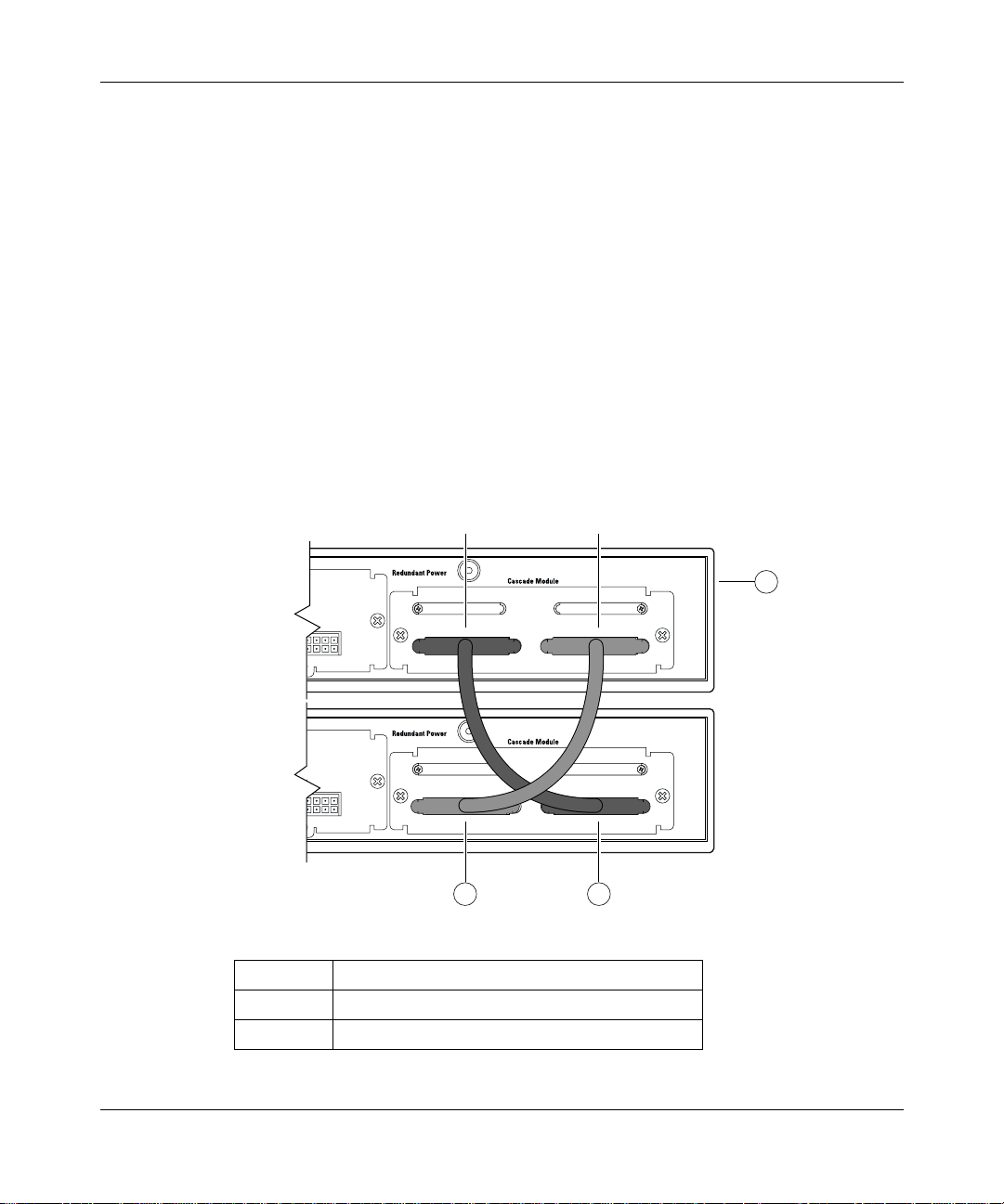
Chapter 2 Network configuration 95
Unit Select switch
The Unit Select switch ( up = Base) de termines the base unit for the stack
configuration (see “Base unit”). The Unit Select switch status is displayed on the
Business Policy Switch LED display panel. When the Unit Select switch is in the
Base (up) position, all other Unit Select switches in the stack configuration must
be set to Off (down).
Cascade A In connector
Provides an attachment point for accepting a cascade cable connection from an
adjacent unit in the stack. A return cable from this unit’s Cascad e A Out connector
to the adjacent unit’s Cascade A In connector completes the stack c onne ct ion (see
the example shown in Figure 13).
Figure 13 Connecting cascade cables
Cascade A Out
Unit 1
Unit 2
3 2
1 Base unit
2 303978-A cascade cable
3 303978-A cascade cable (used for return)
Cascade A In
1
9812EA
Using the Business Policy Switch 2000 Version 1.2
Page 96

96 Chapter 2 Network configuration
Base unit
Note: For stacking three or more units (maximum 8 units per stack),
order the optional 1 meter (39.27 inch) cascade max-return cable (order
number AL2018001).
The base unit is the unique stack unit that you configure with the Unit Select
switch on the front panel of the BayStack 400-ST1 Cascade Module. One
Business Policy Switch in the stack must be configured as the base unit; all other
units in the stack must have their Unit Select switch set to Off (see “Unit Select
switch”). You can assign any single Business Policy Switch as the base unit. If
you are configuring a mixed stack, refer to Appendixes for base unit instructions.
The physical ordering of all of the other units in the stack is determined by the
position of the base unit within the stack. This is important for management
applications that view the physical ordering of the units within the stack.
Some characteristics of the base unit are described in the following sections.
208700-B
Initial installation
During the initial installati on of the stack, the soft ware automatically determines
the physical order of all unit s in th e stack acc ording to t he positi on of the ba se unit
within the stack. Thereafter, the individual units main tain their original unit
numbering, even if you change the position of one or more units in the stack.
(Refer to Chapter 3 for information on renumbering the units using the console
interface (CI) menus and to Using Web-based Management for the Business
Policy Switch 2000 Software Version 1.2 for renumbering the units using the
Web-based management system).
For example, when you initially power up the stack, the base unit becomes unit 1
and the unit that the base unit connects to (via the Cascade A Out cable) becomes
unit 2 (and the next unit is unit 3 and so on), until the maximum stack
configuration ( up to 8 uni ts) is rea ched. I f you ch ange t he bas e uni t to an other unit
in the stack, the new base unit keeps its original unit number in the stack.
Page 97

Chapter 2 Network configuration 97
Stack MAC address
When the switch is participating in a stack configuration, a stack MAC address is
automatically assigned during the stack initialization. The base unit’s MAC
address, with a software offset, is used for the stack MAC address.
For example, if the base unit’s MAC address is 00-00-82-99-44-00, and the stack
software offset is
1F, then the stack MAC address becomes:
00-00-82-99-44-1F
If another unit in the stack is assigned as the base unit, the MAC address of the
new base unit (with offset) now applies to the stack configuration. The original
stack IP address still applies to the new base unit.
Temporary base unit
If an assigned base unit fails, the next unit in the stack order automatically
becomes the new temporary base unit. This change is indicated by the base LED
on the temporary base unit’s LED display panel turning on (amber). For detailed
information about the base LED, see Chapter 1.
This automatic failover is a temporary safeguard only. If the stack configuration
loses power, the temporary base unit will not power up as the base unit when
power is restored. For this reason, you should always assign the temporary base
unit as the base unit (set the Unit Select switch to Base) until the failed unit is
repaired or replaced.
Note: If you do not reassign the temporary base unit as the new base
unit, and the tempora ry b ase uni t fai ls, th e nex t unit direc tly do wnst ream
from this unit becomes the new temporary base unit. This process can
continue until there are only two units left in the stack configuration.
Using the Business Policy Switch 2000 Version 1.2
Page 98

98 Chapter 2 Network configuration
Removing a unit from the stack
If a unit is removed from the stack (therefore operating in sta ndalone mode), the
following switch configuration settings revert back to the settings configured
before the u nit became a member of the stack:
• IP address
• Password: console, Web, Telnet, SNMP (including DM)
• Stack operational mode
• SNMP community strings
Stack configurations
As shown in Figure 14, the cascade connectors and cables on the BayStack
400-ST1 Cascade Module fr ont panel pr ovide the ab ility to st ack up to 8 switches.
With BPS-2000 MDAs installed in each switch, the stack can accommodate a
maximum of 224 switch ports.
208700-B
Because stack parameters are associated with the base unit (see “Base unit”), the
physical stack order depends on the base unit’s position and whether the stack is
configured stack up or stack down.
Stack up configurations
In Figure 14, data flows from the base unit (unit 1) to the next switch, which is
assigned as unit 2, and continues until the last switch in the stack is assigned as
unit 8. The physical order of the switches is from bottom to top (unit 1 to unit 8).
Page 99

Chapter 2 Network configuration 99
Figure 14 Stack up configuration example
Out
1
2
In
3
Unit 8
Unit 7
Unit 6
Unit 5
Unit 4
Unit 3
Unit 2
Unit 1
4
9813EA
Table 7 describes the stack up configuration illustration references.
Table 7 Stack up configuration description
1 Last unit
2 Base unit
3 Cascade Cable (part number 303978-A)
4 Cascade Cable (part number 303979-A)
Using the Business Policy Switch 2000 Version 1.2
Page 100

100 Chapter 2 Network confi gurati on
Stack down configurations
In Figure 15, data flows from the base unit (unit 1) to the next switch, which is
assigned as unit 2, and continues until the last switch in the stack is assigned as
unit 8. The physical order of the switches is from top to bottom (unit 1 to unit 8).
Figure 15 Stack down configuration example
1
In
Unit 1
Unit 2
Unit 3
Unit 4
Unit 5
Unit 6
Unit 7
2
3
Out
Unit 8
4
9814EA
208700-B
 Loading...