

Page 1

Part No. 308684-B Rev 00
March 2000
4401 Great America Parkway
Santa Clara, CA 95054
Installing and Maintaining the Versalar Switch Router 15000
Page 2

Copyright © 2000 Nortel Networks
All rights reserved. Printed in the USA. March 2000.
The information in this document is subject to change without notice. The statements, configurations, technical data,
and recommendations in this document are believed to be accurate and reliable, but are presented without express or
implied warranty. Users must take full respo nsib ility fo r th e ir app lica tio ns o f a ny products specified in this d ocume nt .
The information in this document is proprietary to Nortel Networks NA Inc.
Trademarks
NORTEL NETWORKS is a trademark of Nortel Networks.
Bay Networks is a registered trademark and BCC and Versalar are trademarks of Nortel Networks.
All other trademarks and registered trademarks are t he property of their respective owners.
Statement of Conditions
In the interest of improvi ng internal design, operational function, and/o r relia bi lity, Nortel Network s NA Inc. reserves
the right to make changes to the products described in this document without notice.
Nortel Networks NA Inc. does not assume any liability that may occur due to the use or application of the product(s)
or circuit layout(s) described her ein.
USA Requirements Only
Federal Communications Commission (FCC) Compliance Notice: Radio Frequency Notice
Note: This equipment has been tested and found to comply with the limits for a Class A digital device, pursuant to
Part 15 of the FCC rules. These limits are designed to provide reaso nable protection against harmful interferenc e
when the equipment is operated in a commercial environment. This equipment ge nerates, uses, and can radiate radio
frequency energy. If it is not installed and used in accordance with the instruction manual, it may cause harmful
interference to radio communications. Operation of this equipment in a residential area is likely to cause harmful
interference, in which case users will be required to take whatever measures may be necessary to correct the
interference at their own expense.
European Requirements Only
EN 55 022 Statement
This is to certify that the Nortel Networks Versalar Switch Router 15000 is shielded against the generation of radio
interference in accordance with the application of Council Directive 89/336/EEC, Article 4a. Conformity is declared
by the application of EN 55 022 Class A (CISPR 22).
Warning: This is a Class A product. In a domestic env iron m ent, this product may cause radio interference, in which
case, the user may be required to take appropriate measures.
Achtung: Dieses ist ein Gerät der Funkst örgrenzwertklasse A. In Wohnbereichen können bei Betrieb dieses Gerätes
Rundfunkstörungen auftreten, in welchen Fällen der Benutzer für entsprechende Gegenmaßnahmen verantwortlich
ist.
Attention: Ceci est un produit de Classe A. Dans un environnement domestique, ce produit risque de créer des
interférences radioélectriques, il appartiendra alors à l’utilisateur de prendre les mesures spécifiques appropriées.
T o maintain c omplian ce with FCC radi o freq uency emission lim its, shielde d cables are req uired to c onne ct equipm ent
to other Class A certified devices and the use of quadshield, RG-6/U type CATV cable is required for connection to
the CATV system. Any changes or modifications may void the user’s authorization to operate this equipment.
ii
308684-B Rev 00
Page 3
EC Declaration of Conformity
This product conforms (or these products conform) to the provisions of Council Directive 89/336/EEC and
73/23/EEC. The Declaration of Conformity is available on the Nortel Networks World Wide Web site at
http://libra2.corpwest.baynetworks.com/cgi-bin/ndCGI.exe/DocView/.
Japan/Nippon Requirements Only
Voluntary Control Council for Interference (VCCI) Statement
Taiwan Requirements
Bureau of Standards, Metrology and Inspection (BSMI) Statement
Canada Requirements Only
Canadian Department of Communications Radio Interference Regulations
This digital apparatus (Versalar Switch Router 15000) does not exceed the Class A limits for radio-noise emissions
from digital apparatus as set out in the Radio Interference Regulations of the Canadian Department of
Communications.
Règlement sur le brouillage radioélectrique du ministère des Communications
Cet appareil numérique (Versalar Switch Router 15000) respecte les limites de bruits radioélectriques visant les
appareils numériques de classe A prescrites dans le Règlement sur le brouillage radioélectrique du ministère des
Communications du Canada.
Nortel Networks NA Inc. Software License Agreement
NOTICE: Please carefully read this license agre ement before copying or using the accompanying software or
installing the hardware unit with pre-enabled software (each of which is referred to as “Software” in this Agreement).
BY COPYING OR USING THE SOFTWARE, YOU ACCEPT ALL OF THE TERMS AND CONDITIONS OF
THIS LICENSE AGREEMENT. THE TERMS EXPRESSED IN THIS AGREEMENT ARE THE ONLY TERMS
UNDER WHICH NORTEL NETWORKS WILL PERMIT YOU TO USE THE SOFTWARE. If you do not accept
these terms and conditions, return the product, unused and in the original shipping container, within 30 days of
purchase to obtain a credit for the full purchase price.
308684-B Rev 00
iii
Page 4

1. License Grant. Nortel Networks NA Inc. (“Nortel Networks”) grants the end user of the Software (“Licensee”) a
personal, nonex clusive, nontransferable license : a) to us e the So ftw are eit her on a single c omputer o r, if applicable, on
a single authorized device identified by host ID, for which it was originally acquired; b) to copy the Software solely
for backup purposes in support of authorized use of the Software; and c) to use and copy the associated user manual
solely in support of authoriz ed use of th e Softwa re b y Licen see. Thi s license applies t o the So ftware o nly and d oes not
extend to Nortel Networks Agent software or other Nortel Networks software products. Nortel Networks Agent
software or other Nortel Networks software products are licensed for use under the terms of the applicable N ortel
Networks NA Inc. Software License Agreement that accompanies such software and upon payment by the end user of
the applicable license fees for such software.
2. Restrictions on use; reservation of rights. The Software and user manuals are protected under copyright laws.
Nortel Networks and/or its licensors retain all title and ownership in both the Software and user manuals, including
any revisions made by Nortel Networks or its licensors. Th e copyright notice must be r e produced and incl uded with
any copy of any portion of the Software or user manuals. Licensee may not modify, translate, decompile, disassemble,
use for any competitive analysis, reverse engineer, distribute, or create derivative works from the Software or user
manuals or any copy , in whole or in part. Except as expressly provided in this Agreement, Licensee may not copy or
transfer the Software or user manuals, in whole or in part. The Software and user manuals embody Nortel Networks’
and its licensors’ confidential and proprietary intellectu al pro p erty. Licensee shall not sublicense, assign, or ot he rwise
disclose to any third party the Software, or any information about the operation, design, performance, or
implementation of the Software and user manuals that is confidential to Nortel Networks and its licensors; however,
Licensee may grant permission to its consultants, subcontractors, a nd agents to use the Softw are at Licensee’s facility,
provided they have agreed to use the Software only in accordance with the terms of this license.
3. Limited warranty . Nortel Networks warrants each item of Software, as delivered by Nortel Networks and properly
installed and operated on Nortel Networks hardware or other equipment it is originally licensed for, to function
substantially as described in its accompanying user m anual during its warranty period , which begins on the date
Software is first shipped to Licensee. If an y item of S oftware f ails to so function d uring its w arranty period, as the sole
remedy Nortel Networks will at its discretion provide a suitable fix, patch, or workaround for the problem that may be
included in a future Software release. Nortel Networks further warrants to Licensee that the media on which the
Software is provided will be free from defec ts in materials and wo rkman ship under no rmal use for a peri od of 90 da ys
from the date Software is first shipped to Licensee. Nortel Networks will replace defective media at no charge if it is
returned to Nortel Netw orks during the warranty period along with proof of the date of sh ipment. This warrant y does
not apply if the media has been damaged as a result of accident, misuse, or abuse. The Licensee assumes all
responsibility for selection of the Software to achieve Licensee’s intended results and for the installation, use, and
results obtained from the Software. Nortel Networks does not warrant a) that the functions contained in the software
will meet the Licensee’s requirements, b) that the Software will operate in the hardware or software combinations that
the Licensee may select, c) that the operation of the Software will be uninterrupted or error free, or d) that all defects
in the operation of the Softw are will be corrected . Nortel Network s is not obligate d to remedy an y Software defect that
cannot be reproduced with the latest Software release. These warranties do not apply to the Software if it has been (i)
altered, except by Nortel Networks or in accordance with i ts instructions; (ii) used in conj unction with another
vendor’s product, resulting in the de fect; or (iii) damaged by improper environment, abuse, misuse , accident, or
negligence. THE FOREGOING WARRANTIES AND LIMITATIONS ARE EXCLUSIVE REMEDIES AND ARE
IN LIEU OF ALL OTHER WARRANTIES EXPRESS OR IMPLIED, INCLUDING WITHOUT LIMITAT ION ANY
WARRANTY OF MERCHANTABILITY OR FITNESS FOR A PARTICULAR PURPOSE. Licensee is responsible
for the security of its own data and information and for maintaining adequate procedures apart from the Software to
reconstruct lost or altered files, data, or programs.
4. Limitation of liability. IN NO EVENT WILL NOR TEL NETW ORKS OR ITS LICENS ORS BE LIABLE FOR
ANY COST OF SUBSTITUTE PROCUREMENT; SPECIAL, INDIRECT, INCIDENTAL, OR CONSEQUENTIAL
DAMAGES; OR ANY DAMAGES RESULTING FROM INACCURATE OR LOST DATA OR LOSS OF USE OR
PROFITS ARISING OUT OF OR IN CONNECTION WITH THE PERFORMANCE OF THE SOFTWARE, EVEN
IF NORTEL NETWORKS HAS BEEN ADVISED OF THE POSSIBILITY OF SUCH DAMAGES. IN NO EVENT
SHALL THE LIABILITY OF NORTEL NETWORKS RELATING TO THE SOFTWARE OR THIS AGREEMENT
EXCEED THE PRICE PAID TO NORTEL NETWORKS FOR THE SOFTWARE LICENSE.
iv
308684-B Rev 00
Page 5

5. Government Licensees. This provision applies to a ll Softwa re and docum entation acquired d irectly or i ndirectly by
or on behalf of the United States Government. The Software and documentation are commercial products, licensed on
the open market at market prices, and were developed entirely at private expense and without th e use of any U.S.
Government funds. The license to the U.S. Government is granted only with restricted rights, and use, duplication, or
disclosure by the U.S. Government is subject to the restrictions set forth in subparagraph (c)(1) of the Commercial
Computer Software––Restricte d Rig hts cla u se o f FAR 52.227-19 and the limitations set out in thi s license for civilian
agencies, and subparagraph (c)(1)(ii) of the Rights in Technical Data and Computer Software clause of DFARS
252.227-7013, for agencies of t he Department of Defense or their successors, whichever is applicable.
6. Use of Software in the European Community. This provision applies to all Software acquired for use within the
European Community. If Licensee uses the Software within a country in the European Community, the Software
Directive enacted by the Council of European Communities Directive dated 14 May, 1991, will apply to the
examination of the Software to facilitate interoperability. Licensee agrees to notify Nortel Networks of any such
intended examination of the Software an d may procure support and assista nce from Nortel Networks.
7. Term and termination. This license is effective until terminated; howeve r, all of the restrictions with respect to
Nortel Networks’ copyright in the Software and user manuals will cease being effective at the date of expiration of the
Nortel Networks copyright; those restrictions relating to use and disclosure of Nortel Networks’ confidential
information shall continue in effect. Licensee may terminate this license at any time. The license will automatically
terminate if Licensee fails to comply with any of the terms and conditions of the license. Upon termination for any
reason, Licensee will immediat ely destroy or return to Nortel Networks the Software, user manuals, and all copies.
Nortel Networks is not liable to Licensee for damages in any form solely by reason of the termination of this license.
8. Export and Re-export. Licensee agrees not to export, directly or indirectly, the Software or related technical data
or information without first obtaining any required export licenses or other governmental approvals. Without limiting
the foregoing, Licensee, on behalf of itself and its subsidiaries and affiliates, agrees that it will not, without first
obtaining all export licenses and approvals required by the U.S. Government: (i) export, re-export, transfer, or divert
any such Software or technical data, or any direct product thereof, to any country to which such exports or re-exports
are restricte d or em b argoed under United State s e x port control laws and re gulations, or to any nation al or re sident of
such restricted or embargoed countries; or (ii) provide the Software or related technical data or information to any
military end user or for any military end use, including the design, development, or production of any chemical,
nuclear, or biological weapons.
9. General. If any provision of this Agreement is held to be invalid or unenf orceable by a court of competent
jurisdiction, the remainder of the provisions of this Agreement shall remain in full force and effect. This Agreement
will be governed by the laws of the state of California.
Should you have any questions concerning this Agreement, contact Nortel Netw orks, 4401 Great America Parkway,
P.O. Box 58185, Santa Clara, California 95054-8185.
LICENSEE ACKNOWLEDGES THAT LICENSEE HAS READ THIS AGREEMENT, UNDERSTANDS IT, AND
AGREES TO BE BOUND BY ITS TERMS AND CONDITIONS. LICENSEE FURTHER AGREES THAT THIS
AGREEMENT IS THE ENTIRE AND EXCLUSIVE AGREEMENT BETWEEN NORTEL NETWORKS AND
LICENSEE, WHICH SUPERSEDES ALL PRIOR ORAL AND WRITTEN AGREEMENTS AND
COMMUNICATIONS BETWEEN THE PARTIES PERTAINING TO THE SUBJECT MATTER OF THIS
AGREEMENT. NO DIFFERENT OR ADDITIONAL TERMS WILL BE ENFORCEABLE AGAINST NORTEL
NETWORKS UNLESS NORTEL NETWORKS GIVES ITS EXPRESS WRITTEN CONSENT, INCLUDING AN
EXPRESS WAIVER OF THE TERMS OF THIS AGREEMENT.
308684-B Rev 00
v
Page 6

Page 7

Contents
Preface
Before You Begin ............................................................................................................xvii
Text Conventions ...........................................................................................................xviii
Acronyms ........................... .......................... .......................... ......................... ...............xviii
Hard-Copy Technical Manuals ........................... ....... ...... ....... ...... ...... ....... ...... ................. xx
How to Get Help .............................................................................................................. xx
Chapter 1
Versalar 15000 Hardware Description
Versalar 15000 Components ..........................................................................................1-2
Processor Cards .............................................................................................................1-4
Card Configuration Requirements ............................................................................1-4
Examples of Card Configuration ..............................................................................1-6
Access Processor Cards ..........................................................................................1-6
AP Card Labels .................................................................................................1-7
AP Card LEDs ...................................................................................................1-9
Internet Forwarding Processor Card ......................................................................1-12
System Services Processor Card ..........................................................................1-16
Trunk Processor Card ............................................................................................1-18
ATM TP Card ...................................................................................................1-18
Packet Trunk Processor Card ..........................................................................1-21
Interface Cards .............................................................................................................1-24
Access Interface Cards ..........................................................................................1-24
Hex T3 (T3) Interface Card ..............................................................................1-25
Access Redundancy Module Interface Card ..................................................1-26
Dual OC-3 Single-Mode or Multimode Channelized Access Interface Card ...1-28
Dual OC-3 (SMF or MMF) ATM Access Interface Card ...................................1-30
System Services Processor Interface Cards ..........................................................1-31
SSP Interface Console Card .............................. ....... ...... ...... ...........................1-32
308684-B Rev 00 vii
Page 8

SSP Interface Ethernet Card ..........................................................................1-34
Trunk ATM Interface Cards ....................................................................................1-36
Single-Mode and Multimode Interfaces ...........................................................1-36
OC-12c/STM-4c ATM Interface Cards .............................................................1-36
Quad OC-3 ATM Trunk Interface Card .............................................................1-38
Trunk Ethernet Interface Cards ..............................................................................1-39
1000M-LX Ethernet Trunk Interface Card ........................................................1-39
1000M-SX Ethernet Trunk Interface Card ........................................................1-41
Chapter 2
Installing the Versalar 15000
Preparing to Install the Versalar 15000 ..........................................................................2-2
Verifying Shipment Contents ....................................................................................2-2
Supplying Equipment ...............................................................................................2-5
Management Console .......................................................................................2-5
Cables ............................................. ...... ....... ...... ....................................... ...... ...2-5
Hardware for Mounting the Versalar 15000 in an Equipment Rack ...................2-6
Verifying Site Requirements .....................................................................................2-7
Space Requirements ........................................................................................2-7
AC Input Electrical Requirements ......................................................................2-7
DC Input Electrical Requirements .....................................................................2-8
Environmental Requirements ............................................................................2-9
Installing the Versalar 15000 ... ....... ...... ....... ...... ....... ...... ....... ...................................... .2-10
Positioning the Versalar 15000 on a Flat Surface ..................................................2-10
Mounting the Versalar 15000 in a Four-Post Rack .................................................2-10
Mounting the Versalar 15000 in a 19-Inch Rack ..............................................2-13
Mounting the Versalar 15000 in an Optional 23-Inch Rack .............................2-16
Mounting the Versalar 15000 in a Two-Post Rack ..................................................2-20
Chapter 3
Installing Power Supplies
Power Modules ...............................................................................................................3-1
Installing a Redundant DC Power Module .....................................................................3-4
Removing and Replacing the Front Bezels ..............................................................3-4
Removing and Installing a Power Filler Plate ...........................................................3-7
The DC Power Module .............................................................................................3-8
viii 308684-B Rev 00
Page 9

Removing a DC Power Module ..............................................................................3-10
Connecting to the DC Power Source ............................................................................3-12
Installing Optional AC Power Module(s) .......................................................................3-19
Mounting the Separate AC Power Unit ..................... ....... ...... ...... ....... ....................3-19
Installing an AC Powe r Module ..............................................................................3-20
Removing an AC Power Module ............................................................................3-22
Connecting to the Optional AC Power Module(s) .........................................................3-23
Chapter 4
Installing Processor and Interface Cards and Connecting Equipment
Location of the Processor and Interface Cards ..............................................................4-2
Attaching the Antistatic Wrist Strap ................................................................................4-3
Installing and Replacing a Processor Card ...................................................................4-6
Removing a Processor Card ...................................................................................4-6
Installing a Processor Card ......................................................................................4-8
Installing and Removing an Interface Card ..................................................................4-12
Removing an Interface Card .................................................................................4-12
Installing an Interface Card ...................................................................................4-14
Connecting Communications Cables ............................................................................4-19
Connecting to an Ethernet Interface ......................................................................4-20
Connecting to an OC-12c/STM-4c or an OC-3 ATM Access Interface ...................4-21
Connecting to a T3 Interface ..................................................................................4-22
Connecting to an Alarm ........................................................................................4-24
Connecting Console Equipment ...................................................................................4-25
Connecting a PC with a 25-pin Comm Port to the Console Port ...........................4-25
Connecting a Terminal with a 25-pin Comm Port to the Console Port ...................4-29
Connecting a PC with a 9-pin Comm Port to the Console Port ..............................4-31
Connecting a Modem .............................................................................................4-32
Chapter 5
Operating the Versalar 15000
Verifying a Successful Installation ..................................................................................5-2
Turning the Versalar 15000 On and Off ..........................................................................5-3
Turning the Versalar 15000 with a DC Power Source On and Off ............................5-3
Turning the Versalar 15000 with the AC Power Unit On and Off ..............................5-4
Resetting the Versalar 15000 .........................................................................................5-5
308684-B Rev 00 ix
Page 10

Muting an Alarm ............................................................................................................5-6
Removing Flash or Option Memory Cards from the SSP Card ......................................5-7
Installing Flash or Option Memory Cards in the SSP Card ............................................5-9
Protecting Memory Card Files ......................................................................................5-10
Appendix A
Technical Specifications
Physical, Electrical, and Environmental Specifications .................................................. A-2
Hardware Communications Options .............................................................................. A-2
Ethernet 10/100BASE-T Interface ........................................................................... A-3
Local Console Interface .......................................................................................... A-4
Service Modem Interface .. ....... ...... ....... ...... ....... ...... ....... ...................................... .. A-5
OC-12c/STM-4c ATM Interface Card Specifications ...................................................... A-6
DS3 Interface Card Specifications ................................................................................. A-7
Versalar 15000 Card Glossary
Index
x 308684-B Rev 00
Page 11

Figures
Figure 1-1. Location of the Customer-Replaceable Units ..........................................1-3
Figure 1-2. M13/DS3 CAP Card .................................................................................1-8
Figure 1-3. IFP Card ...................................... ....... ...... ....... ...... ...... ...........................1-13
Figure 1-4. SSP Card .......... ....... ...... ....... ...... ....... ...... ....................................... ...... .1-16
Figure 1-5. ATM TP Card .........................................................................................1-19
Figure 1-6. Packet Trunk Processor Card .................................................................1-22
Figure 1-7. T3 Interface Card ...................................................................................1-25
Figure 1-8. ARM Interface Card ...............................................................................1-27
Figure 1-9. Dual OC-3 (SMF or MMF) Channelized Access Interface Card ............1-29
Figure 1-10. SSP-C Interface Console Card ..............................................................1-32
Figure 1-11. SSP-E Interface Ethernet Card ..............................................................1-34
Figure 1-12. OC-12c/STM-4c ATM Interface Card .....................................................1-37
Figure 1-13. Quad OC-3 ATM Trunk Interface Card ...................................................1-38
Figure 1-14. 1000M-LX Ethernet Trunk Interface Card ..............................................1-40
Figure 2-1. Accessories in the Versalar 15000 Shipping Container ...........................2-4
Figure 2-2. SC Duplex to SC Duplex Cable ...............................................................2-6
Figure 2-3. Three Versalar 15000 DC Platforms and Two AC Platforms in a
Four-Post Rack ......................................................................................2-12
Figure 2-4. Attaching Angle Brackets in a 19-Inch Rack ..........................................2-14
Figure 2-5. Installing the Versalar 15000 in a 19-Inch Four-Post Rack ....................2-15
Figure 2-6. Attaching Angle Brackets in a 23-Inch Rack ..........................................2-17
Figure 2-7. Repositioning the Vertical Flanges for Either a Two- or Four-Post Rack 2-18
Figure 2-8. Installing the Versalar 15000 in a 23-Inch Four-Post Rack ....................2-19
Figure 2-9. Repositioning the Vertical Flanges in a Two-Post Rack .........................2-21
Figure 2-10. Installing the Versalar 15000 in a Two-Post Rack ..................................2-23
Figure 3-1. Versalar 15000 DC Power Module ...........................................................3-2
Figure 3-2. Front and Rear Views of the Versalar 15000 with Two Optional
AC Power Modules ...................................................................................3-3
Figure 3-3. Removing the Versalar 15000 Front Bezels .............................................3-5
308684-B Rev 00 xi
Page 12

Figure 3-4. Replacing the Versalar 15000 Front Bezels .............................................3-6
Figure 3-5. Removing or Installing a Power Filler Plate ..............................................3-8
Figure 3-6. Removing or Installing a DC Power Module ...........................................3-11
Figure 3-7. Terminal Block and Circuit Breakers on the Back of the
Versalar 15000 .......................................................................................3-13
Figure 3-8. DC Power Terminal Block and Power Switch .........................................3-14
Figure 3-9. Removing the Strain Relief Bracket .......................................................3-15
Figure 3-10. Attaching the DC Input Leads ................................................................3-16
Figure 3-11. Installing the Strain Relief Bracket .............................. ...........................3-18
Figure 3-12. Mounting the Separate AC Power Unit ................. ...... ...........................3-20
Figure 3-13. Removing or Installing an AC Power Module .........................................3-21
Figure 3-14. Two Versalar 15000 Platforms with the AC Power Unit in a
Four-Post Rack ......................................................................................3-24
Figure 3-15. AC Management Cable Location ...........................................................3-26
Figure 4-1. Location of the Processor and Interface Cards ........................................4-2
Figure 4-2. Connecting the Wrist Strap Jack to the Front Ground Clip ......................4-4
Figure 4-3. Connecting the Wrist Strap Jack to the Back Ground Clip .......................4-5
Figure 4-4. Removing a Processor Card ....................................................................4-7
Figure 4-5. Processor Card Slots (Front of Chassis) ..................................................4-9
Figure 4-6. Positioning a Processor Card .................................................................4-10
Figure 4-7. Installing a Processor Card ....................................................................4-11
Figure 4-8. Removing an Interface Card ..................................................................4-13
Figure 4-9. Interface Card Slots (Back of Chassis) ..................................................4-15
Figure 4-10. Positioning an Interface Card .................................................................4-16
Figure 4-11. Installing an Interface Card ....................................................................4-17
Figure 4-12. Connecting a UTP Cable to the SSP Interface Ethernet Card ...............4-20
Figure 4-13. Connecting a Duplex Fiber Cable to the OC-12c/STM-4c or
OC-3 Interface Card ...............................................................................4-21
Figure 4-14. T3 Interface Card Connector Pairs ........................................................4-22
Figure 4-15. Connecting a Coaxial Cable to the T3 Interface Card ............................4-23
Figure 4-16. Alarm Terminal Block on the SSP Interface Cards ................................4-24
Figure 4-17. Connecting the Console Cable to a PC with a 25-pin Comm Port .........4-27
Figure 4-18. Attaching the Null Modem Crossover Adapter .......................................4-28
Figure 4-19. Connecting a Console Cable to a Terminal with a 25-pin Comm Port ...4-30
Figure 4-20. Connecting the Console Cable to a PC with a 9-pin Comm Port ...........4-32
Figure 4-21. Connecting a Modem to the Versalar 15000 ..........................................4-34
xii 308684-B Rev 00
Page 13

Figure 4-22. Dual Modem Access with a Single Telco Line .......................................4-35
Figure 5-1. Versalar 15000 Power Switch ..................................................................5-3
Figure 5-2. Versalar 15000 Reset Switch ...................................................................5-5
Figure 5-3. Alarm Mute Button ...................................................................................5-6
Figure 5-4. Removing the Memory Card Access Cover .............................................5-7
Figure 5-5. Removing a Flash or Option Memory Card .............................................5-8
Figure 5-6. Inserting a Flash or Option Memory Card ...............................................5-9
Figure 5-7. Memory Card Read-Write Protect Switch ..............................................5-11
308684-B Rev 00 xiii
Page 14

Page 15

Tables
Table 1-1. Installation Possibilities ............................................................................1-4
Table 1-2. AP Card Labels ........................................................................................1-7
Table 1-3. AP Card LEDs ..........................................................................................1-9
Table 1-4. DS3 Status LEDs ...................................................................................1-10
Table 1-5. OC-3 Status LEDs .................................................................................1-11
Table 1-6. IFP Card LEDs ......... ...... ....................................... ...... ....... ...... ....... ...... .1-1 4
Table 1-7. SSP Card LEDs .......................................................... ....... ...... ....... ...... .1-1 7
Table 1-8. ATM OC-12c/STM TP Card LEDs ..........................................................1-20
Table 1-9. Packet TP Card LEDs ............................................................................1-23
Table 1-10. T3 Interface Card LEDs .........................................................................1-26
Table 1-11. ARM Interface Card LED .......................................................................1-28
Table 1-12. Dual OC-3 (SMF or MMF) Channelized Access Interface Card LEDs ...1-30
Table 1-13. Dual OC-3 (SMF or MMF) ATM Access Interface Card LEDs ...............1-31
Table 1-14. SSP Interface Console Card LEDs ................. ...... ...... ....... ...... ....... ...... .1 -33
Table 1-15. SSP Interface Ethernet Card LEDs ........................................................1-35
Table 1-16. OC-12c/STM-4c ATM Interface Card LEDs ...........................................1-37
Table 1-17. Quad OC-3 ATM Trunk Interface LEDs ..................................................1-39
Table 1-18. 1000M-LX Ethernet Trunk Interface LEDs .............................................1-41
Table 2-1. Versalar 15000 Shipping Accessories .....................................................2-3
Table 2-2. Network Cables ........................................................................................2-5
Table 2-3. Space Requirements ...............................................................................2-7
Table 2-4. Electrical Requirements for AC Model (23-inch chassis) .........................2-7
Table 2-5. Wall Receptacle Requirements for AC Power ..........................................2-8
Table 2-6. Electrical Requirements for DC Model .....................................................2-8
Table 2-7. Environmental Requirements ...................................................................2-9
Table 3-1. DC Power Module LEDs ..........................................................................3-2
Table 3-2. AC Power Module LEDs ..........................................................................3-4
Table 4-1. PC Parameters ...................................................... ...... ....... ...... ....... ...... .4-2 6
Table 4-2. Terminal Parameters ..............................................................................4-29
308684-B Rev 00 xv
Page 16

Table 4-3. PC Parameters ...................................................... ...... ....... ...... ....... ...... .4-3 1
Table 4-4. Modem Settings ....................................... ....... ...... .................................4-33
Table A-1. 10/100BASE-T Interface Pin Assignments ............................................. A-3
Table A-2. Local Console Port DB-9 Pin Assignments ............................................. A-4
Table A-3. Service Modem Port DB-9 Pin Assignments .......................................... A-5
Table A-4. Maximum Fiber Optic Power Budget and Transmission Distances ......... A-6
Table A-5. Specifications for the DS3 Interface ........................................................ A-7
xvi 308684-B Rev 00
Page 17

Preface
The Nortel Networks™ Versalar™ Switch Router 15000 is a next-generation
Internet Protocol (IP) router designed to provide access, traffic management, and
accounting information for over 1000 simultaneous IP sessions. Carrier
Networking Services is the software for the Ve rsalar Switch Router 15000.
This guide provid es inst ructi ons for inst alli ng the Versalar 15000 fo r the first time
or for replacing any Versalar 15000 customer-replaceable unit (CRU).
In this guide, the Versalar Switch Router 15000 is referred to as the “Versalar
15000.”
Before You Begin
This guide is intended for qualified service personnel who are installing the
Versalar 15000 for the first time or who need to install or replace any Versalar
15000 CRU. A quali fi ed service perso n should ha v e appropriat e technical training
and experience and be aware of the hazards involved in installing and replacing
CRUs.
Caution:
tion.
Before installing the Versalar 15000, ensure that all network wiring has been
installed on the premises using standard cable-system practices.
Before turning on the Versalar 15000 for the first time, contact your network
administrator to determine which software configuration option to use.
308684-B Rev 00
The Versalar 15000 is intended for use in a restricted access loca-
xvii
Page 18

Installing and Maintaining the Versalar Switch Router 15000
Text Conventions
This guide uses the following text conventions:
Acronyms
bold text
italic text Indicates new terms, book titl es, and variables in
This guide uses the following acronyms:
AIS alarm indication signal
AP access processor
APS automatic protection switching
ARM access redundancy module
ASIC application-specific integrated circuit
ATM asynchronous transfer mode
ATP ATM trunk processor
Indicates command names and options and text that
you need to enter.
diags
Example: Enter the
command syntax descriptions.
command.
xviii
CAP channelized access processor
CBR constant bit rate
CRU customer-replaceable unit
CTS clear to send
DCD data carrier detect
DIMM dual inline memory module
DS3 digital service level 3
DSR data set ready
DTR data terminal ready
308684-B Rev 00
Page 19

Preface
EIA Electronic Industries Associati on
EMI electromagnetic interference
GND ground
IFP Internet forwarding processor
IP Internet P rotocol
LED light emitting diode
LOF loss of frame
LOS loss of signal
MMF multimode fiber
NC normally closed
NEMA National Electrical Manufacturers Association
NO normally open
OC-3 Optical Carrier-level 3
OC-12 Optical Carrier-level 12
308684-B Rev 00
POS packet over sonet
RDI remote defect indication
RFU reserved for future use
RLSD received line signal detection
RTS ready to send
Rxd receive data
SMF single-mode fiber
SSP system services processor
STM synchronous transfer mode
TP trunk processor
Txd transmit
UBR unspecified bit rate
UTP unshielded twisted pair
VBR variable bit rate
xix
Page 20

Installing and Maintaining the Versalar Switch Router 15000
Hard-Copy Technical Manuals
You can print selected technical manuals and release notes free, directly from the
Internet. Go to support.baynetworks.com/library/tpubs/. Find the product for
which you need documentation. Then locate the specific category and model or
version for your hardw are or soft ware product . Usi ng Adobe Ac robat Re ader, you
can open the manuals and releas e notes, search for the sections you ne ed, and print
them on most standard printers. You can download Acrobat Reader free from the
Adobe Systems Web site, www.adobe.com.
You can purchase selected documentation sets, CDs, and technical publications
through the collateral catalog. The catalog is located on the World Wide Web at
support.baynetworks.com/catalog.html and is divided into sections arranged
alphabetically:
• The “CD ROMs” section lists available CDs.
• The “Guides/Books” section lists books on technical topics.
• The “Technical Manuals” section lists available printed documentation sets.
How to Get Help
xx
If you purchased a service contract for your Nortel Networks product from a
distributor or authorized reseller, contact the technical support staff for that
distributor or reseller for assistance.
If you purchased a Nort el Net wor ks ser vice pr ogram, c ontact one of the f ollowing
Nortel Networks Technical Solutions Centers:
Technical Solutions Center Telephone Number
Billerica, MA 800-2LANWAN (800-252-6926)
Santa Clara, CA 800-2LANWAN (800-252-6926)
Valbonne, France 33-4-92-96-69-68
Sydney, Australia 61-2-9927-8800
Tokyo, Japan 81-3-5740-1700
308684-B Rev 00
Page 21
Chapter 1
Versalar 15000 Hardware Description
This chapter introduc es the Versalar Switch Rout er 15000 hardw ar e and des cribes
the light emitting diodes (LEDs) on each component. It includes the following
topics:
Topic Page
Versalar 15000 Components 1-2
Processor Cards 1-4
Interface Cards 1-24
308684-B Rev 00
1-1
Page 22

Installing and Maintaining the Versalar Switch Router 15000
Versalar 15000 Components
The Versalar 15000 consists of a chassis that contains slots for these modules:
• Processor cards (front of chassis)
-- Five access processor (AP) cards
-- Three Internet for warding processor (IFP) cards
-- Two system services processor (SSP) cards
-- Two trunk processor (TP) cards
• Interface cards (rear of chassis)
-- For redundant configurations: four access interface cards and one access
redundancy module (ARM) interface card
-- For nonredundant configurations: five access interface cards
-- One SSP interface Ethernet card
-- One SSP interface console card
-- Two trunk interface cards
1-2
• Two DC power modules
• One fan tray
308684-B Rev 00
Page 23
Versalar 15000 Hardware Description
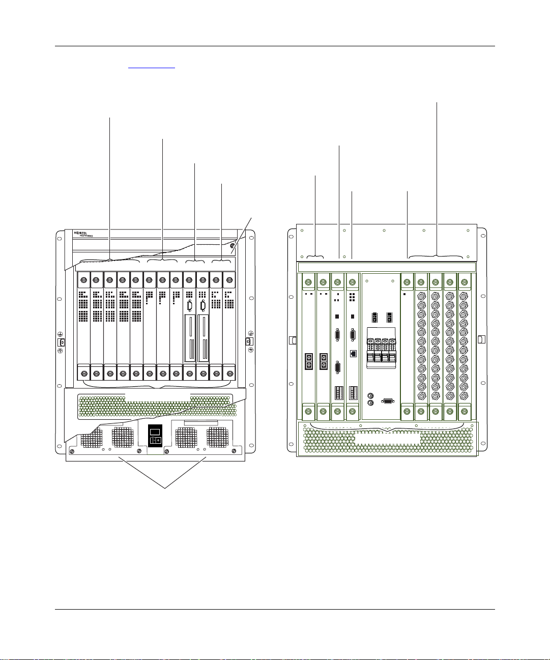
Figure 1-1 shows the location of the Versalar 15000 customer-replaceable units
(CRUs).
Access interface cards
AP cards
IFP cards
SSP cards
TP cards
VERSARLAR Switch Router 15000
12 3 45 678 9 10 11 12
Processor cards
Fan tra y
SSP interface
console card
Trunk interface
cards
11
12
SSP
interface
Ethernet
card
9876
10
Optional
ARM
card
4
5
3
1
2
Front of chassis
Rear of chassis
DC-input power supply modules
Figure 1-1. Location of the Customer-Replaceable Units
308684-B Rev 00
Interface cards
VRS0002A
1-3
Page 24

Installing and Maintaining the Versalar Switch Router 15000
Processor Cards
In this guide, the term processor card refers to the following cards:
• Access processor (AP) card
• Internet forwarding processor (IFP) card
• System services processor (SSP) card
• Trunk processor (TP) card
The processor cards perform the network layer protocol processing on the data
packets.
• AP and TP cards provide layer 2 processing.
• IFP cards provide layer 3 processing.
• SSP cards provide layer 4 and above processing.
Card Configuration Requirements
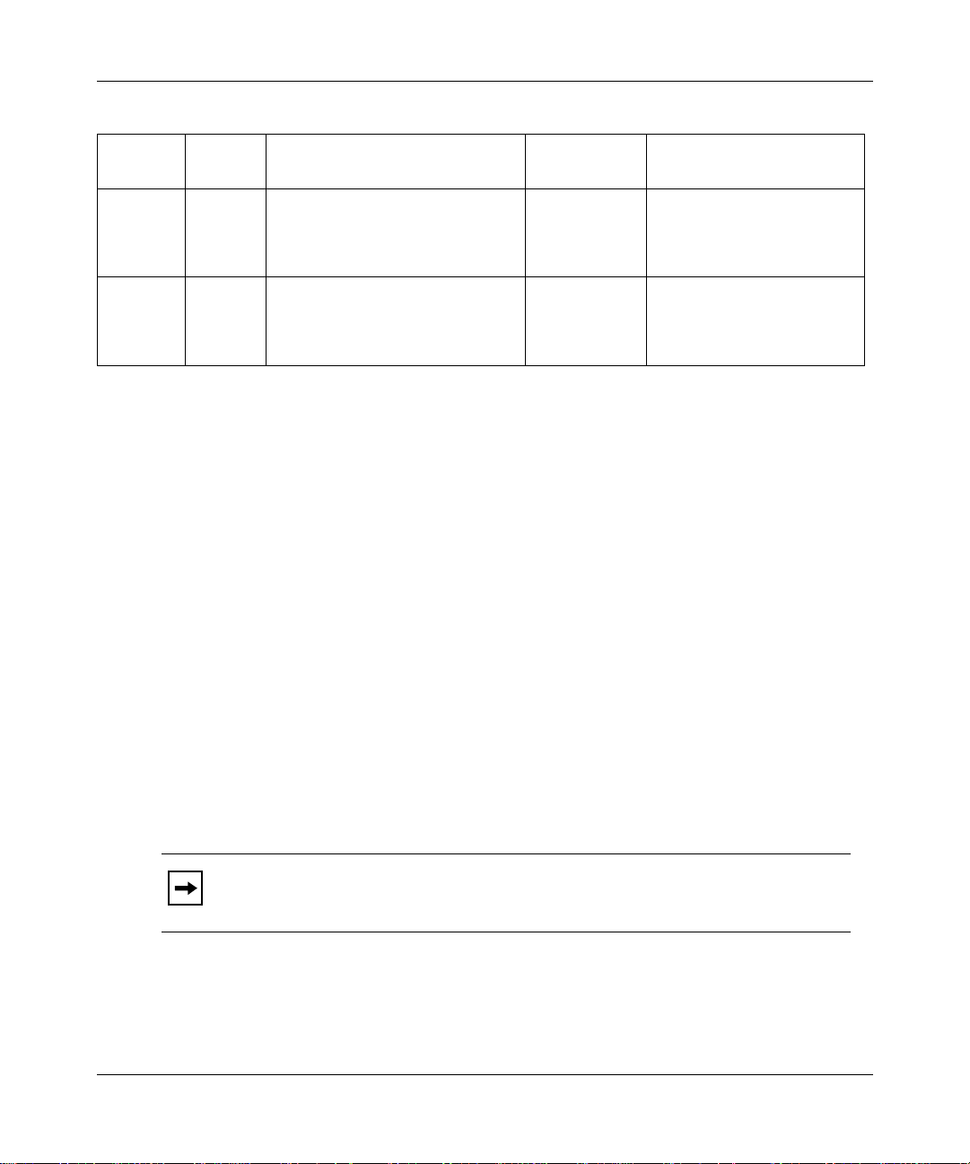
Table 1-1 shows possibilities for installing the cards into the card slots in the
Versalar 15000.
Table 1-1. Installation Possibilities
AP Cards TP Cards Base Configuration
1 0 1 AP card in slot 1
1 IFP card in slot 6
1 SSP card in slot 9
2 0 2 AP cards in slots 1 and 2
1 IFP card in slot 6
1 SSP card in slot 9
3 0 3 AP cards in slots 1, 2, and 3
2 IFP cards in slots 6 and 8
1 SSP card in slot 9
4 0 4 AP cards in slots 1, 2, 3, and 4
2 IFP cards in slots 6 and 8
1 SSP card in slot 9
1-4
Performance
Configuration Redundant Configuration
None 1 AP card in slot 5
1 IFP card in slot 8
1 SSP card in slot 10
None 1 AP card in slot 5
1 IFP card in slot 8
1 SSP card in slot 10
None 1 AP card in slot 5
1 IFP card in slot 7
1 SSP card in slot 10
None 1 AP card in slot 5
1 IFP card in slot 7
1 SSP card in slot 10
(continued)
308684-B Rev 00
Page 25

Versalar 15000 Hardware Description
Table 1-1. Installation Possibilities
AP Cards TP Cards Base Configuration
5 0 5 AP cards in slot s 1 , 2, 3, 4, and 5
3 IFP cards in slots 6, 7, and 8
1 SSP card in slot 9
1 1 1 AP card in slot 1
1 TP card in slot 11
1 IFP card in slot 6
1 SSP card in slot 9
2 1 2 AP cards in slots 1 and 2
1 TP card in slot 11
1 IFP card in slot 6
1 SSP card in slot 9
3 1 3 AP cards in slots 1, 2, and 3
1 TP card in slot 11
2 IFP cards in slots 6 and 8
1 SSP card in slot 9
4 1 4 AP cards in slots 1, 2, 3, and 4
1 TP card in slot 11
2 IFP cards in slots 6 and 8
1 SSP card in slot 9
5 1 5 AP cards in slot s 1 , 2, 3, 4, and 5
1 TP card in slot 11
3 IFP cards in slots 6, 7, and 8
1 SSP card in slot 9
1 2 1 AP card in slot 1
2 TP cards in slots 11 and 12
2 IFP cards in slots 6 and 8
1 SSP card in slot 9
2 2 2 AP cards in slots 1 and 2
2 TP cards in slots 11 and 12
2 IFP cards in slots 6 and 8
1 SSP card in slot 9
3 2 3 AP cards in slots 1, 2, and 3
2 TP cards in slots 11 and 12
2 IFP cards in slots 6 and 8
1 SSP card in slot 9
(continued)
Performance
Configuration Redundant Configuration
None N/A
None 1 AP card in slot 5
1 IFP card in slot 8
1 SSP card in slot 10
1 IPF card in
slot 8
None 1 AP card in slot 5
1 IFP card in
slot 7
None N/A
None 1 AP card in slot 5
None 1 AP card in slot 5
1 IFP card in
slot 7
1 AP card in slot 5
1 SSP card in slot 10
1 IFP card in slot 7
1 SSP card in slot 10
1 AP card in slot 5
1 SSP card in slot 10
1 IFP card in slot 7
1 SSP card in slot 10
1 IFP card in slot 7
1 SSP card in slot 10
1 AP card in slot 5
1 SSP card in slot 10
(continued)
308684-B Rev 00
1-5
Page 26
Installing and Maintaining the Versalar Switch Router 15000
Table 1-1. Installation Possibilities
AP Cards TP Cards Base Configuration
4 2 4 AP cards in slots 1, 2, 3, and 4
2 TP cards in slots 11 and 12
2 IFP cards in slots 6 and 8
1 SSP card in slot 9
5 2 5 AP cards in slot s 1 , 2, 3, 4, and 5
2 TP cards in slots 11 and 12
3 IFP cards in slots 6, 7, and 8
1 SSP card in slot 9
(continued)
Examples of Card Configuration
The performance configuration is additive from the base configuration. For
example, to set up the performance configuration for four AP cards and two TP
cards, add an IFP card in slot 7 to the base configuration. The resulting
configuration is:
AP1, AP2, AP3, AP4, TP11, TP12, IFP6, IFP7, IFP8, SSP9
The redundant configuration is additive from the performance configuration. For
example, to set up the redundant configuration for four AP cards and two TP
cards, add an AP card in slot 5 and an SSP card in slot 10. The resulting
configuration is:
Performance
Configuration Redundant Configuration
1 IFP card in
slot 7
None N/A
1 AP card in slot 5
1 SSP card in slot 10
AP1, AP2, AP3, AP4, AP5, TP11, TP12, IFP6, IFP7, IFP8, SSP9, SSP10
Access Processor Cards
The Versalar 15000 supports four AP cards in chassis slots 1 to 5.
Note:
If you do not use all the slots from 1 to 5, use t he lowest-numbered slots
first.
1-6
308684-B Rev 00
Page 27
Versalar 15000 Hardware Description
Each AP card services the access interface card corresponding to the slot number
of the installed AP card. For example, the AP card installed in processor card slot
2 services the access interface card installed in interface card slot 2.
The function of a physical interface card in the rear of the chassis must
Note:
match the function of the AP card in the corresponding slot in the front of the
chassis, for example, ATM to ATM or T3 to T3.
An AP card installed in slo t 5 ca n provide failov er se rvi ce to the AP cards in slots
1 to 4. For more informat ion about redundancy, see “Access Redundancy Module
Interface Card” on page 1-26
.
The Versalar 15000 supports four types of AP cards:
• The M13 channelized acc ess processor (CAP) card is use d f or subrate T1 and
T1 applications.
• The DS3 CAP card provides high-speed access over DS3 lines.
• The hybrid M13 and clear-channel DS3 CAP card provides both T1 and
high-speed access.
308684-B Rev 00
• The ATM (asynchronous transfer mode) a cce ss p roc essor card provides ATM
access via DS3 or OC-3 lines.
Each AP card consists of a printed circuit board, an EMI card shield, a bezel with
status LEDs, and 2 captive screws to secure the card in place (Figure 1-2
).
AP Card Labels
The AP cards are differentiated from each other by their labels only. Otherwise,
the cards appear the same.
Table 1-2
Table 1-2. AP Card Labels
Card Type Label
M13 CAP
Clear-channel DS3 CAP-DS3
Hybrid M13/clear DS3 CAP-M13/DS3
ATM access processor AAP
lists the label identifiers for all types of AP cards.
1-7
Page 28
Installing and Maintaining the Versalar Switch Router 15000
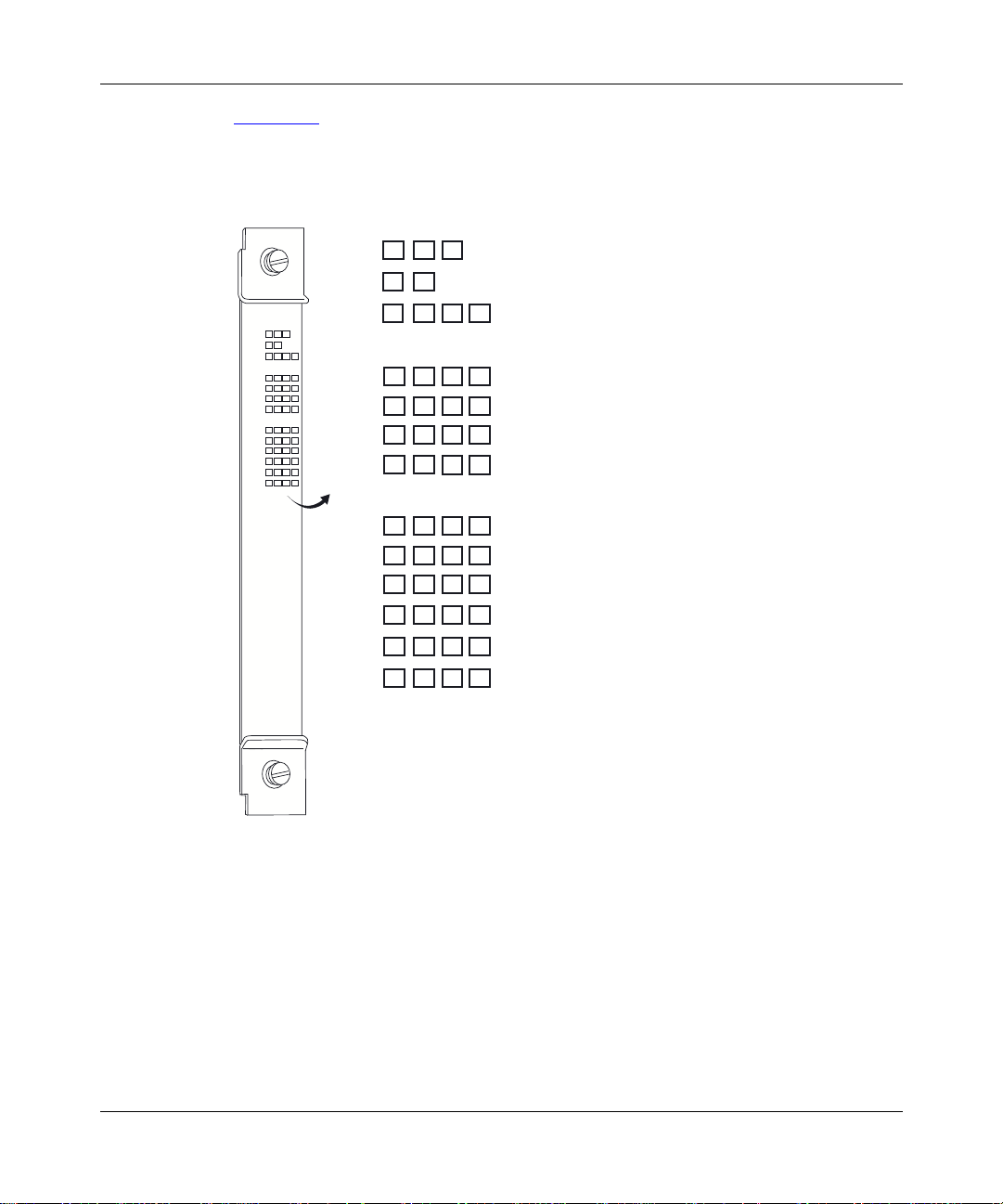
Figure 1-2 shows an example of an M13/DS3 CAP card. All the AP cards are
identical to this card. This illustration shows the card’s unique label identifier as
well as the position of the LEDs.
Stat Run
Pwr
CAP
M13/DS3
Phy
N+1
CAP
M13/DS3
Port 1A
Port 1B
Port 2A
Port 2B
Slot
Port 1
Port 2
Port 3
Port 4
Port 5
Port 6
Pwr
Stat Run
N+1
Phy
1 234
OC3 Status
Sync APS RDI Test
DS3 Status
Sync Maj Min Test
Slot
Port 1A
Port 1B
Port 2A
Port 2B
Port 1
Port 2
Port 3
Port 4
Port 5
Port 6
1 2
OC3 Status
Sync
DS3 Status
Sync
34
APS RDI Test
Maj
Min
Test
BAC0045A
1-8
Figure 1-2. M13/DS3 CAP Card
308684-B Rev 00
Page 29

Versalar 15000 Hardware Description
AP Card LEDs
Table 1-3
describes the LEDs for all AP ca rds. This gr oup of LEDs is the same for
all the AP cards.
Table 1-3 . AP Card LEDs
LED State Meaning
Pwr Off CAP card is turned off.
On (green) CAP card is turned on.
Stat Off LED is not functioning.
On (green) CAP card is operating normally.
Flashing (green) Power-up diagnostic testing is in progress. Diagnostic
testing occurs when y ou cold-st art the module by cycli ng
power, issuing the
Command Console (BCC
with the power on.
On (amber) Diagnostic testing failed. The CAP car d is waiting for an
automatic attempt to reinitiate diagnostic testing. If the
Stat LED lights amber again, call the Nortel Networks
Technical Solutions Center.
Run Off The processor code is not loaded.
On (green) The processor code loaded successfully.
Flashing (green) The processor code is loading.
On (amber) A failure was detected.
Phy Off No interface card is installed in the interface card slot
corresponding to this CAP card.
On (green) A T3 or ARM interface card is present in the interface
card slot corresponding to this CAP card.
N+1 Off N+1 failover operation is not engaged.
On (green) N+1 failover operation is engaged; that is:
• CAP card is present in processor card slot 5.
• ARM card is present in interface card slot 5.
• N+1 failover condition occurred.
• CAP card present in processor card slot 5 assumes
the function of the failing CAP card.
Slots1 to 4 Off N+1 failover operation is not engaged for this slot.
On (green) Indicates which CAP card failed. The N+1 CAP card is
servi cing the CAP card installed in this slot.
command from the Bay
diags
™
), or installing the CAP card
308684-B Rev 00
1-9
Page 30

Installing and Maintaining the Versalar Switch Router 15000
Table 1-4 describes the DS3 status LEDs for all the AP cards.
Table 1-4. DS3 Status LEDs
LED State Meaning
Ports 1 to 6
Sync
Flashing
Ports 1 to 6
Maj
Ports 1 to 6
Min
Ports 1 to 6
Test
Off Port is not configured or the software is not initialized.
On (green) Port has achieved frame synchronization.
Port has not achieved frame synchronization. A loss of
(green)
Off No major alarm is de tected on this port.
On (amber) A major alarm is dete cted on this port. A loss of frame
Off No minor alarm is de tected on this port.
On (amber) A minor alarm is detected on this port. A remote alarm
Off Port is operating normally.
On (green) Port is operating in a DS3 loopback state.
frame (LOF) or loss of signal (LOS) condition exists.
(LOF), loss of signal (LOS), or alarm indication signal
(AIS) condition exists.
indication (R-AIS) condition exists.
1-10
308684-B Rev 00
Page 31

Versalar 15000 Hardware Description
Table 1-5 describes the OC-3 status LEDs for all types of AP cards. The OC-3
status LEDs are the same for all AP cards.
Table 1-5. OC-3 Status LEDs
LED State Meaning
Sync (port
Automatic Protection
Switching (APS)
Test (port n) Off Port is operating in through mode.
RDI (port
) Off Frame synchronization is not detected on port.
n
On (green) Frame synchronization is achieved on port.
Off APS is disabled on port.
On (amber) APS is enabled on port.
On (green) Port is operating in a loopback state.
) Off No remote fault is detected on port.
n
On (green) Remote fault is detected on port.
308684-B Rev 00
1-11
Page 32

Installing and Maintaining the Versalar Switch Router 15000
Internet Forwarding Processor Card
The Intern et forward processor (IFP) card provides layer 3 IP switching for the
Versalar 15000. The Versalar 15000 can support three IFP car ds in chassi s slot s 6
to 8.
Two or three IFP cards provide high-availability operation. If you have an access
card in slot 1 or 2, use slot 6 for the IFP card. If you have an access card in slot 3
or 4, use slot 7 for the IFP card. Slot 8 is for redundancy; however, it can be used
in normal system operation.
Note:
If you do not use all the IFP slots, use the lowest numbered IFP slots
first.
1-12
308684-B Rev 00
Page 33

Versalar 15000 Hardware Description
Figure 1-3 shows an IFP card.
Pwr Stat Run
IFP
AP1 SSP1
AP2
Pwr Stat Run
IFP
AP1 SSP1
TP1
TP2
SSP2
AP2
AP3
AP4
AP5
AP3
AP4
AP5
SSP2
TP1
TP2
308684-B Rev 00
BAC0005A
Figure 1-3. IFP Card
1-13
Page 34

Installing and Maintaining the Versalar Switch Router 15000
Table 1-6 describes the IFP card LEDs.
Table 1-6. IFP Card LEDs
LED State Meaning
Pwr Off Power is off.
On (green) Power is on.
Stat Off LED is not functioning.
On (green) IFP card is operating normally.
Flashing
(green)
On (amber) Diagnostic testing failed. The IFP card is waiting for an automatic
Run Off Processor code is not loaded.
On (green) Boot process is complete.
Flashing
(green)
On (amber) Fault is detected.
AP1 Off IFP card is not processing inbound packets for the CAP card
On (green) IFP card is processing inbound packets for the CAP card present
AP2 Off IFP card is not processing inbound packets for the CAP card
On (green) IFP card is processing inbound packets for the CAP card present
AP3 Off IFP card is not processing inbound packets for the CAP card
On (green) IFP card is processing inbound packets for the CAP card present
AP4 Off IFP card is not processing inbound packets for the CAP card
On (green) IFP card is processing inbound packets for the CAP card present
Power-up diagnostic testing is in progress. Diagnostic testing
occurs when you cold-start the module by cycling power, issuing
the
the power on.
attempt to reinitiate diagnostic testing. If the Stat LED lights
amber again, call the Nortel Networks Technical Sol utions Center .
Booting.
present in processor card slot 1.
in processor card slot 1.
present in processor card slot 2.
in processor card slot 2.
present in processor card slot 3.
in processor card slot 3.
present in processor card slot 4.
in processor card slot 4.
command from the BCC, or installing the IFP card with
diags
(continued)
1-14
308684-B Rev 00
Page 35

Versalar 15000 Hardware Description
Table 1-6. IFP Card LEDs
LED State Meaning
AP5 Off IFP card is not processing inbound packets for the CAP card
present in processor card slot 5.
On (green) IFP card is processing inbound packets for the CAP card present
in processor card slot 5.
SSP1 Off IFP card is not processing inbound packets for the SSP card
present in processor card slot 9.
On (green) IFP card is processing inbound packets for the SSP card present
in processor card slot 9.
SSP2 Off IFP card is not processing inbound packets for the SSP card
present in processor card slot 10.
On (green) IFP card is processing inbound packets for the SSP card present
in processor card slot 10.
TP1 Off IFP card is not processing inbound packets for the trunk
processor card present in processor card slot 11.
On (green) IFP card is processing inbound packets for the trunk processor
card pres ent in processor card slot 11.
TP2 Off IFP card is not processing inbound packets for the trunk
processor card present in processor card slot 12.
On (green) IFP card is processing inbound packets for the trunk processor
card pres ent in processor card slot 12.
(continued)
308684-B Rev 00
1-15
Page 36

Installing and Maintaining the Versalar Switch Router 15000
System Services Processor Card
The systems services processor (SSP) card is the central processing resource on
which the network layer protocols run. The SSP card is responsible for Versalar
15000 route determination, statistics, and central management. The Versalar
15000 can support two SSP cards in slots 9 and 10.
The SSP card consists of a pr inted circui t board wit h status LEDs, 1 flash memory
card slot, 2 option card slots, and a modem connector (Figure 1-4
Pwr Stat Run Mstr
SSP
SSP
Pwr
Stat Run Mstr
TempFan Maj Min
Diag Test Count
3210
T emp Fan Maj Min
Diag T est Count
).
Modem
SQUEEZE TO REMOVE
Boot Flash
1
Option Cards
32
SQUEEZE TO REMOVE
3210
Flash memory card slot
Option card slots
Figure 1-4. SSP Card
BAC0003A
1-16
308684-B Rev 00
Page 37

Versalar 15000 Hardware Description
Table 1-7 describes the SSP card LEDs.
Table 1-7 . SSP Card LEDs
LED State Meaning
Pwr Off Power is off.
On (green)
Stat Off LED is not functioning.
On (green) SSP card is operating normally.
Flashing (green) Power-up diagnostic testing is in progress.
On (amber)
Run Off Processor code is not loaded.
On (green) Boot process is complete.
Flashing (green) Software initialization and loading are in progress.
On (amber) Fault is detected.
Mstr Off SSP card is not controlling the system resources.
On (green) SSP card is controlling the system resources.
Temp Off When the air temperature exceeds 65
On (green) System temperature is normal.
On (amber) Air tempe rature exceeds 45
Fan Off Fan is operating normally.
On (amber)
Maj Off No major software a larm is detected.
On (amber) Majo r fault i s detected, suc h as a compone nt fail ure
Power is on
Diagnostic testing o c curs when you c old-start the
module by cycling power, issuing the
command from the BCC, or installing the SSP card
with the power on.
Diagnostic testing failed. The SSP card is waiting
for an automatic attempt to reinitiate diagnostic
testing. If the Stat LED lights amber again, call the
Nortel Networks Technical Solutions Center.
system will shut down.
Fan is defective
or interface failure.
.
diags
0
C, the
0
C.
.
(continued)
308684-B Rev 00
1-17
Page 38

Installing and Maintaining the Versalar Switch Router 15000
Table 1-7 . SSP Card LEDs
LED State Meaning
Min Off No minor software alarm is detected.
On (amber) Minor fault is detected, such as a far-end alarm or
Diag Test
Count
Off Nortel Networks Carrier Networking Services
On (green) When the Nortel Networks Carrier Networking
Trunk Processor Card
The Versalar 15000 provides tr unk line se rvice s for ATM and gigabit Eth ern et. To
accommodate trunk services, the Versalar 15000 supports up to two trunk
processor cards in slots 11 and 12.
This section contains information about the following TP cards:
• ATM OC-12c/STM TP card
• Packet TP card
(continued)
remote peer down.
operating system is not executing.
Services operati ng system is executing, it uses
these lights to count time.
1-18
ATM TP Card
The ATM TP card provides an OC-3/OC12c/STM-4c optical link-level interface,
constant bit rate (CBR) service, variable bit rate (VBR) service, and unspecified
bit rate (UBR) service.
Figure 1-5
shows the ATM OC-12c/STM TP card.
308684-B Rev 00
Page 39

Versalar 15000 Hardware Description
Pwr Stat Run
ATP
Phy
Pri
Pwr Stat Run
ATP
Phy
Sar
Sec
Pri
IFP
Test RDILink
Port 1
Port 2
Port 3
Port 4
Port 1
Port 2
Port 3
Port 4
Sec
Test RDILink
Sar
IFP
308684-B Rev 00
BAC0006B
Figure 1-5. ATM TP Card
1-19
Page 40

Installing and Maintaining the Versalar Switch Router 15000
Table 1-8 describes the ATM OC-12c/STM TP card LEDs.
Table 1-8.
LED State Meaning
Pwr Off Power is off.
Stat Off LED is not functioning.
Run Off Processor code is not loaded.
Phy O ff Trunk interface card is not installed.
Sar Off Not loaded.
Pri IFP Off Primary IFP card is not in use.
Sec IFP Off Secondary IFP card is not in use.
Link (port
ATM OC-12c/STM TP
On (green) Power is on.
On (green) TP card is operating normally.
Flashing (green) Power-up diagnostic testing is in progress.
Diagnostic testing o c curs when you c old-start the
module by cycling power, issuing the
command from the BCC, or installing the TP card
with the power on.
On (amber) Power-up diagnostic testing failed. The TP card is
waiting for an automatic attempt to reinitiate
diagnostic testing. If the Stat LED lights amber
again, call the No rtel Netwo rks Technical Solu tions
Center.
On (green) Boot process is complete.
Flashing (green) Booting.
On (amber) A fault is detected. Call the Nortel Networks
Technical Solutions Center.
On (green) Trunk interface card is present.
Flashing (green) Booting.
On (green) Boot is complete.
On (green) Primary IFP card is in use.
On (green) Secondary IFP card is in use.
) Off Frame synchronization is not detected on the po rt.
n
On (green) Frame synchronization is achieved on the port.
Card LEDs
diags
(continued)
1-20
308684-B Rev 00
Page 41

Versalar 15000 Hardware Description
Table 1-8.
LED State Meaning
Test (port n) Off Port is operating in through mode.
RDI (port
ATM OC-12c/STM TP
On (green) Port is operating in a loopback state.
) Off No remote fault is detected on the port.
n
On (green) Remote fault is detected on the port.
Card LEDs
(continued)
Packet Trunk Processor Card
The Ethernet trunk servi ce pro vides proces sing for one 1000 Base gig abit Ethern et
traffic stream. You can configure the packet trunk processor cards in slots 11 and
12, with gigabit Ethernet cards in corresponding slots.
308684-B Rev 00
1-21
Page 42

Installing and Maintaining the Versalar Switch Router 15000
Figure 1-6 shows the packet trunk processor card.
Stat Run
Pwr
PTP
Phy
POS Enet
Pri Sec
Pwr
PTP
Phy POS Enet
Pri Sec
IFP
POS APSRDI
Link
Enet
Port 1
Port 2
Port 3
Port 4
Stat Run
Test
10/100
IFP
POS
Enet
Port 1
Port 2
Port 3
Port 4
Link
Test
RDI APS
10/100
1-22
VRS0139A
Figure 1-6. Packet Trunk Processor Card
308684-B Rev 00
Page 43

Versalar 15000 Hardware Description
Table 1-9 describes the Packet TP card LEDs.
Table 1-9. Packet TP Card LEDs
LED State Meaning
Pwr Off Power is off.
On (green) Power is on.
Stat Off The LED is not functioning.
On (green) The TP card is operating normally.
Flashing (green) Power-up diagnostic testing is in progress.
Diagnostic testing occurs when you cold-start
the module by cycling power, issuing the
command from the BCC, or installing the TP
card with the power on.
On (amber) Power-up diagnostic testing failed. The TP card
is waiting for an automatic attempt to reinitiate
diagnostic testing. If the Stat LED lights amber
again, call the Nortel Networks Technical
Solutions Center.
Run Off The processor code is not loaded.
On (green) The boot process is complete.
Flashing (green) The router is booting.
On (amber) A fault is detected. Call the Nortel Networks
Technical Solutions Center.
Phy Off The trunk interface card is not installed.
On (green) The trunk interface ca rd is present.
POS Off POS interface is not configured. (RFU)
On (green) POS interface is configured. (RFU)
Enet Off Enet interface is not configured.
On (green) Enet interface is configured.
Pri IFP Off The primary IFP card is not in use.
On (green) The primary IFP card is in use.
Sec IFP Off The secondary IFP card is not in use.
On (green) The secondary IFP card is in use.
Link (port
) Off Link is not detected on the port.
n
On (green) Link is achieved on the port.
diags
(continued)
308684-B Rev 00
1-23
Page 44

Installing and Maintaining the Versalar Switch Router 15000
Table 1-9. Packet TP Card LEDs
LED State Meaning
Test (port n) Off The port is operating in normal operation mode.
RDI (POS)
(port
n
10/100 (Enet)
(port
n
APS Valid only when POS is configured. (RFU)
Interface Cards
The interface cards provide the link to the physical network. They receive data
from the network, extract data, and forward the data to the processor cards for
routing. When a processor card has data to send to a port, the interface cards
accept the data and transmit it in the appropriate fo rmat.
In this guide, the term interface card refers to the following cards:
(continued)
On (green) The port is operating in a loopback mode.
Off No remote fault is detected on the port. (RFU)
)
On (green) A remote fault is detected on the port. (RFU)
Off 1000 Mb (GIG) or 10 Mb interface is configured.
)
On (green) 100 Mb interface is configured.
• Access interface cards -- T3, ARM, Quad DS3 for channelized AP, Dual
OC-3 SMF and MMF for channelized AP cards, Dual OC-3 SMF and MMF
for ATM access
• SSP interface cards -- SSP interface console and SSP interface Ethernet cards
• Trunk interface cards -- ATM OC-12c/STM-4c SMF and MMF, Quad OC-3
ATM trunk interface, ATM OC-3 trunk phy, and Ethernet SX and LX trunk
interface cards
Access Interface Cards
The Versalar 15000 access interface cards occupy chassis slots 1 to 5 and support
network interfaces for AP cards. The access interface cards are the Hex T3 (T3),
ARM, Quad DS3, or Dual OC-3 inter f a ce c ar ds, e ach of which is described in the
sections that fo llo w. (Note that the ARM interf ace c ard must be i nstal led in slot 5. )
1-24
308684-B Rev 00
Page 45

Versalar 15000 Hardware Description
Hex T3 (T3) Interface Card
The T3 interface card provides physical line interfaces for six T3 lines. The
Versalar 15000 supports four or five T3 interface cards in slots 1 to 5.
Figure 1-7
Stat
N+1
T3 Interface
RX
1
TX
RX
2
TX
RX
3
TX
RX
4
TX
RX
5
TX
RX
6
TX
shows the T3 interface card.
Rear of chassis
T3 interface card
slots 1-4 or 1-5
N+1
Stat
T3 Interface
308684-B Rev 00
BAC0063A
Figure 1-7. T3 Interface Card
1-25
Page 46

Installing and Maintaining the Versalar Switch Router 15000
Table 1-10 describes the T3 inte rface card LEDs.
Table 1-10. T3 Interface Card LEDs
LED State Meaning
Stat Off Power is off.
On (green) T3 card is operating normally.
On (amber) Diagnostic testing failed. The T3 card is waiting for
an automatic attempt to reinitiate diagn ostic testing.
If the Stat LED lights amber again, call the Nortel
Networks Technical Solutions Center.
N+1 Off N+1 failover operation not engaged for this slot.
On (green) The CAP card installed in slot 5 is servicing this T3
interface card , rather than the CAP card install ed in
the slot corresponding to this T3 interface card.
Access Redundancy Module Interface Card
To enable N+1 redundant operation, you must install an access redundancy
module (ARM) interface card in slot 5 of the chassis. The redundant AP card in
slot 5 can then assume the processing duties of a failing AP card. With an ARM
card installed in interface card slot 5 and a hybrid M13 and clear-channel DS3
CAP card installed in processor card slot 5, the Versalar 15000 supports failover
of mixed clear-channel and channelized T3 configurations.
1-26
If a CAP card is inst alle d in p rocess or car d slo t 5, t he N+1 and Sl ot LEDs indic ate
which T3 interface card is being serviced. For more information about N+1
redundancy a nd failover, see Managing and Troubleshooting the Versalar Switch
Router 15000.
308684-B Rev 00
Page 47

Versalar 15000 Hardware Description
Figure 1-8 shows the ARM interface card.
Stat
Stat
BAC0064A
308684-B Rev 00
Figure 1-8. ARM Interface Card
1-27
Page 48

Installing and Maintaining the Versalar Switch Router 15000
Table 1-11 describes the ARM interface card LEDs.
Table 1-11. ARM Interface Card LED
LED State Meaning
Stat Off Power is off.
On (green) ARM card is operating normally.
On (amber) Diagnostic testing failed. The ARM card is waiting
for an automatic attempt to reinitiate diagnostic
testing. If the Stat LED lights amber again, call the
Nortel Networks Technical Solutions Center.
Dual OC-3 Single-Mode or Multimode Channelized Access Interface Card
The Dual OC-3 (SMF or MMF) channelized access interface card provides
physical line interfaces for two channelized OC-3 lines with APS failover
switching. (For information about SMF and MMF cards, refer to “
and Multimod e Interfaces” on page 1-36.) The Versalar 15000 supports four or
five OC-3 interface cards in slots 1 to 5.
Single-Mode
1-28
308684-B Rev 00
Page 49

Versalar 15000 Hardware Description
Figure 1-9 shows the Dual OC-3 channelized access interface card.
N+1
Pwr
2xOC3 M13 MMF
Access Interface
Lof2BLos
Lof2BLos
Lof2BLos
Pwr
N+1
2xOC3 M13 MMF
Access Interface
Lof2BLos
VRS0130A
Figure 1-9. Dual OC-3 (SMF or MMF) Channelized Access Interface Card
308684-B Rev 00
1-29
Page 50

Installing and Maintaining the Versalar Switch Router 15000
Table 1-12 describes the Dual OC-3 (SMF or MMF) channelized access interface
card LEDs.
Table 1-12. Dual OC-3 (SMF or MMF) Channelized Access Interface Card
LEDs
LED State Meaning
Pwr Off Power is off.
On (green) OC-3 card is operating normally.
On (amber) Diagnostic testing failed. The O C-3 card is w ai ting
for an automatic attempt to reinitiate diagnostic
testing. If the Stat LED lights amber again, call the
Nortel Networks Technical Solutions Center.
N+1 Off N+1 failover operation is not engaged for this slot.
On (green) The AP card installed in slot 5 is servicing this
OC-3 interface card, rather than the AP card
installed in the slot corresponding to this OC-3
interface card.
LOF Off Loss of frame not detected.
On (amber) Loss of frame detected.
LOS Off Loss of signal not detected.
On (amber) Loss of signal detected.
1-30
Dual OC-3 (SMF or MMF) ATM Access Interface Card
The Dual OC-3 (SMF or M MF ) ATM access interface card pro vi des physical line
interfaces for two ATM lines with APS failover switching. The Versalar 15000
supports four or five OC-3 interface cards in slots 1 to 5. (For information about
SMF and MMF cards, refer to “
Single-Mode and Multimode Interfaces” on page
1-36.)
Refer to Figure 1-9 on page 1-29 for an illustration of a Dual OC-3
Note:
channelized access interface card that looks identical to the Dual OC-3 ATM
access interface card.
308684-B Rev 00
Page 51

Versalar 15000 Hardware Description
Table 1-13 describes the Dual OC-3 (SMF or MMF) ATM access interface card
LEDs.
Table 1-13. Dual OC-3 (SMF or MMF) ATM Access Interface Card LEDs
LED State Meaning
Pwr Off Power is off.
On (Green) OC-3 card is operating normally.
On (Amber) Diagnostic testing failed. The OC-3 card is waiting
for an automatic attempt to reinitiate diagnostic
testing. If the Stat LED lights amber again, call the
Nortel Networks Technical Solutions Center.
N+1 Off N+1 failover operation is not engaged for this slot.
On (Green) The AP card installed in slot 5 is servicing this
OC-3 interface card, rather than the AP card
installed in the slot corresponding to this OC-3
interface card.
LOF Off Loss of frame not detected.
On (Amber) Loss of frame detected.
LOS Off Loss of signal not detected.
On (Amber) Loss of signal detected.
System Services Processor Interface Cards
The Versalar 15000 system services processor (SSP) interface cards occupy
chassis slots 9 and 10. They provide dedicated interfaces for out-of-band
management, as well as system-wide status. The SSP interface cards are the SSP
interface console card and the SSP interface Ethernet card, each of which is
described in the sections that follow.
308684-B Rev 00
1-31
Page 52

Installing and Maintaining the Versalar Switch Router 15000
SSP Interface Console Card
The Versalar 15000 supports one SSP interface console card in slot 10 of the
chassis. The SSP interface console card consists of a bezel with status LEDs, a
9-pin D-sub console connector, an alarm terminal block, and a mute button
(Figure 1-10
).
Alarm
mute
button
Pwr
Min
Mute
Alarm Mute
Pwr
SSP Interface
Console
SSP Interface
Cosole
Maj
Alarm
Console
Min
Mute
Maj
Alarm
Console connector
Alarm
Min NO
Min COM
Min NC
Alarm terminal block
Maj NO
Maj COM
Maj NC
1-32
VRS0121B
Figure 1-10. SSP-C Interface Console Card
308684-B Rev 00
Page 53

Versalar 15000 Hardware Description
Table 1-14 describes the SSP interface console card LEDs.
Table 1-14. SSP Interface Console Card LEDs
LED State Meaning
Pwr Off Power is off.
On (green) Power is on.
On (amber) SSP interface console card is defective. Call the
Nortel Networks Technical Solutions Center.
Min Alarm Off No minor software alarm detected.
On (amber) Minor fault detect ed, such as a far-end alarm or
remote peer down.
Maj Alarm Off No majo r software alarm detected.
On (amber) Major fault detected, such as a component failure
or interface failure.
Mute Off Major and minor alarm relays are enabled.
On (amber) Major and minor alarm relays are disabled.
308684-B Rev 00
1-33
Page 54

Installing and Maintaining the Versalar Switch Router 15000
SSP Interface Ethernet Card
The Versalar 15000 supports one SSP interface Ethernet card in slot 9 of the
chassis. The SSP interface Ethernet card supports the 10 Mb Ethernet interface.
The SSP interface E thernet card consists of an Etherne t 10/100 Mb conne ctor , and
an alarm terminal block and mute button (Figure 1-11
Lnk
Pwr
SSP Interface
Ethernet
Maj
Alarm
Alarm
mute
button
Lnk
Pwr
SSP Interface
Ethernet
Dup
10/100
Min
Maj
Alarm
Mute
Alarm Mute
Dup 10/100
Min
Mute
Enet 10/100
Ethernet 10/100 connector
).
1-34
Alarm
Min NO
Min COM
Min NC
Maj NO
Maj COM
Maj NC
Alarm terminal block
VRS0123B
Figure 1-11. SSP-E Interface Ethernet Card
308684-B Rev 00
Page 55

Versalar 15000 Hardware Description
Table 1-15 describes the SSP interface Ethernet card LEDs.
Table 1-15. SSP Interface Ethernet Card LEDs
LED State Meaning
Lnk Off Ethernet link is down.
On (green) Link pulse received.
Flashing (green) Port is transmitting or receiving data.
Pwr Off Power is off.
On (green) Power is on.
On (amber) SSP interface Ethernet card is defective. Call the
Nortel Networks Technical Solutions Center.
Dup Off SSP interface Ethernet card is configured for half
duplex.
On (green) SSP interface Ethernet card is configured for full
duplex.
10/100 Off SSP interface Ethernet port is configured for
10 Mb/s.
On (green) Reserved for future use.
Min Alarm Off No minor software alarm detected.
On (amber) Minor fault detected, such as a far-end alarm or
remote peer down.
Maj Alarm Off No major software alarm detected.
On (amber) Major fault detected, such as a component failure
or interface failure.
Mute Off Major and minor alarm relays are enabled.
On (amber) Major and minor alarm relays are dis abled.
308684-B Rev 00
1-35
Page 56

Installing and Maintaining the Versalar Switch Router 15000
Trunk ATM Interface Cards
The Versalar 15000 trunk interface cards occupy chassis slots 11 and 12 and
support network interfaces for TP cards. This section contains information about
the following cards:
• ATM OC-12c/STM-4c single-mode and multimode trunk interface cards
• Quad OC-3 ATM trunk interface card
Single-Mode and Multimode Interfaces
The single-mode fiber (SMF) and multimode fiber (MMF) interfaces operate with
a wide variety of ATM switches and are compliant with Bellcore standards. You
can view modes as bundles of light entering the fiber at a particular angle.
Single-mode fiber allows only one mode of light to propagate through the fiber;
multimode fiber allows multiple modes of light to propagate.
Depending on the entry angles, multiple modes of light propagating through the
fiber travel different distances, thus causing them to arrive at their destination at
different times. This phenomenon is called modal dispersion, and it results in
single-mode fiber being capable of higher bandwidth and greater cable run
distances than multimode fiber. For more information about transmission
distances for single-mode and multimode fiber, see “OC-12c/STM-4c ATM
Interface Card Specifications” on page A-6.
1-36
OC-12c/STM-4c ATM Interface Cards
The ATM OC-12c/STM-4c single-mode and multimode trunk interface cards
provide an ATM OC-12c/STM-4c link-level interface. The Versalar 15000
supports one or two OC-12c/STM-4c single-mode cards, one or two
OC-12c/STM-4c multimode cards, or one single-mode and one multimode card.
You can differentiate multimode cards from single-mode cards by their labels, as
shown in Figure 1-12
, which shows a multimode card.
308684-B Rev 00
Page 57

Versalar 15000 Hardware Description
Pwr LOF
OC12 Interface
Multi-Mode
Pwr LOF
OC-12 Interface
Multi-Mode
308684-B Rev 00
BAC0009A
Figure 1-12. OC-12c/STM-4c ATM Interface Card
Table 1-16 describes the OC-12c/STM-4c interface card LEDs.
Table 1-16. OC-12c/STM-4c ATM Interface Card LEDs
LED State Meaning
Pwr Off Power is off.
On (green) Power is on and operating normally.
LOF Off Loss of frame not detected.
On (amber) Loss of frame detected.
1-37
Page 58

Installing and Maintaining the Versalar Switch Router 15000
Quad OC-3 ATM Trunk Interface Card
Figure 1-13
shows t he Quad OC-3 ATM trunk interface card. The car d c onsi st s of
a printed circuit board, an EMI card shield, a bezel with status LEDs, an d 2
captive screws to secure the card in place. You can differentiate multimode cards
from single-mode cards by their labels, as shown in Figure 1-13
, which shows a
multimode card.
Pwr
LOF2LOF1
4xOC3 ATM MMF
Trunk Interface
LOF4LOF3
1
2
Pwr
LOF2LOF1
4xOC3 ATM MMF
Trunk Interface
LOF4LOF3
1-38
3
4
VRS0132A
Figure 1-13. Quad OC-3 A TM Trunk Interface Card
308684-B Rev 00
Page 59

Table 1-17 describes the Quad OC-3 ATM trunk interface LEDs.
Table 1-17. Quad OC-3 ATM Trunk Interface LEDs
LED State Meaning
Pwr Off Power is off.
On (green) Power is on and operating normally.
LOF Off Loss of frame not detected.
(port 1-4) On (amber) Loss of frame detected.
Trunk Ethernet Interface Cards
The Versalar 15000 trunk Ethernet interface cards occupy chassis slots 11 and 12
and support network interfaces for TP cards. This section contains information
about the following cards:
• 1000M-LX Ethernet trunk interface card
• 1000M-SX Ethernet trunk interface card
Versalar 15000 Hardware Description
308684-B Rev 00
1000M-LX Ethernet Trunk Interface Card
The LX Ethernet trunk interface card is a single-port 1000-base LX Ethernet
module. The Versalar 15000 supports one or two LX Ethernet trunk interface
cards.
1-39
Page 60

Installing and Maintaining the Versalar Switch Router 15000
Figure 1-14 shows the 1000M-LX Ethernet trunk interface card.
TX
RX
Pwr SD
1000M-LX Enet
Trunk Interface
Link/UD
1000M-LX Enet
Trunk Interface
SD
Pwr
LinkU/D
VRS0136A
Figure 1-14. 1000M-LX Ethernet Trunk Interface Card
1-40
308684-B Rev 00
Page 61

Versalar 15000 Hardware Description
Table 1-18 shows the 1000M-LX Ethernet trunk interface card LEDs.
Table 1-18. 1000M-LX Ethernet Trunk Interface LEDs
LED State Meaning
Pwr Off Power is off.
On (green) Power is on.
SD Off No signal detected.
On (green) Optical signal detected.
Link U/D Off Link is down.
On (green) Link is up.
1000M-SX Ethernet Trunk Interface Card
The SX Ethernet trunk interface card is a single-port 1000-base SX Ethernet
module. The Versalar 15000 supports one or two SX Ethernet trunk interface
cards.
308684-B Rev 00
The 1000M-SX Ethernet trunk interface card looks exactly the same as the
1000M-LX Ethernet trunk interface card. The LEDs are also the same. Refer to
Figure 1-14
and Table 1-18 for more information about the card and the LEDs.
1-41
Page 62

Page 63

Chapter 2
Installing the Versalar 15000
This chapter describes how to install the Versalar 15000 chassis. It includes the
following topics:
Topic Page
Preparing to Install the Versalar 15000 2-2
Installing the Versalar 15000 2-10
308684-B Rev 00
2-1
Page 64

Installing and Maintaining the Versalar Switch Router 15000
Preparing to Install the Versalar 15000
Before beginning the inst allation, verify that:
• Your shipment is complete and undamaged.
• You have the cables, tools, and other equipment that you need.
• Your installation site meets the physical, electrical, and environmental
requirements.
The sections that follow provide information to help you prepare for installation.
Caution:
tion.
The Versalar 15000 is intended for use in a restricted access loca-
Verifying Shipment Contents
Inspect all items for shippi ng damage. If you de tect a ny damage, do no t inst all t he
Versalar 15000. Call the Norte l Networks Technical Solutions Center in your area
(see “How to Get Help” on page xx).
In addition to the Versalar 15000 and this guide, your shipping container contains
seve ral hardw are accessor ies. Verify that the items in the shipping cont ainer match
those on the shipment packing list.
2-2
308684-B Rev 00
Page 65

Installing the Versalar 15000
Use Table 2-1 as a checklist when verifying the contents of the shipping container.
Table 2-1. Versalar 15000 Shipping Accessories
Check Accessory Use To
• One 15-foot AT standard molded
serial cable
• One null modem crossover adapter
• One 10-foot console serial cable
Bracket kit containing:
• Two angle brackets
• Ten cagenut screws with washers
• Ten cagenuts
ESD wrist strap Direct the discharge of static
Connect an optional
management console.
Mount the Versalar 15000 in an
equipment rack .
(Use the cagenuts only if th e
equipment rack does not have
threaded rail holes.)
electricity from your body to the
chassis.
308684-B Rev 00
2-3
Page 66

Installing and Maintaining the Versalar Switch Router 15000
Figure 2-1 illustrates the accessories in the Versalar 15000 shipping container.
ESD wrist strap
Console cable
(DB-9 receptacle
to DB-25 plug cable)
Console cable
(DB-9 receptacle
to DB-9 -receptacle cable)
DB-25 receptacle
null modem adapter
Ten cagenuts
Ten #10 cagenut screws
and washers
Two angle brackets
Figure 2-1. Accessories in the Versalar 15000 Shipping Container
2-4
BAC0050A
308684-B Rev 00
Page 67

Supplying Equipment
You might need items that are not included in the Versalar 15000 accessory
package. Before installing the Versalar 15000 hardware, ensure that you have all
the cables, tools, and other equipment that you need.
Management Console
To configure startup options and to monitor the results of startup diagnostics, you
can attach an optional VT-100 console or equivalent, such as a PC terminal
emulator. Or, you can attach an AT-compatible modem to allow dial-in access to
startup configuration and diagnostics.
Cables
Unless you specifically ordered them, the cables required for your network
configurat io n are not included in the Versalar 15000 a cce ssory package. If you do
not have the proper cables, contact your network administrator.
Installing the Versalar 15000
Table 2-2
Table 2-2 . Network Cabl es
Order No. Length Physical Cable Description Connection
7163 9 ft (2.7 m) SC duplex to SC duplex
7165 9 ft (2.7 m) SC duplex to SC duplex
Figure 2-2
lists the network cables that are required:
Nortel Networks PHY A or
connectors; multimode fiber
cable
connectors; single-m ode fiber
cable
PHY B interface to a type SC
network connection
Nortel Networks PHY A or
PHY B interface to a type SC
network connection
shows both the multimode (order no. 7163) and the single-mode
(order no. 7165) SC duplex cables.
308684-B Rev 00
2-5
Page 68

Installing and Maintaining the Versalar Switch Router 15000
A
9 ft
(2.7 m)
Figure 2-2. SC Duplex to SC Duplex Cable
Hardware for Mounting the Versalar 15000 in an Equipment Rack
CAB0035
2-6
To install the Versalar 15000 in an equipment rack, you need a Phillips
screwdriver and a rack that meets the following specifications:
• Heavy-duty steel construction
• Electronic Industries Association (EIA) standard hole-spacing
• Four-post rack with width of 19 in. (48.26 cm) and depth of 24 in. (60.96 cm)
• Four-post rack with width of 23 in. (58.42 cm) and depth of 24 in. (60.96 cm)
• Two-post rack with width of 19 in. (48.26 cm)
If the rack does not have threaded rail holes, you must use the supplied cagenuts
(see Figure 2-1
) with the cagenut screws.
308684-B Rev 00
Page 69

Verifying Site Requirements
Ensure that the installation site meets the space, electrical, and environmental
requirements listed in this section. See Appendix A, “Technical Specifications,”
for more information.
Installing the Versalar 15000
Space Requirements
The installation site must provide sufficient free space around the Versalar 15000
to ensure proper ventilation and access for servicing (Table 2-3)
Table 2-3. Space Requirements
Width Minimum Depth Depth for Servicing
19 in. (48.2 cm) 22 in. (55.8 cm) 46.2 in. (1 m 17.5 cm)
.
AC Input Electrical Requirements
If you have purchased the AC power option, the installation site must meet the
following electr ical requirements for AC power (Table 2-4)
Table 2-4. Electrical Requirements for AC Model (23-inch chassis)
Input Voltage
180-264 volts (V)
50-60 hertz (Hz), +/-3%
Maximum Input Current Maximum System Power
14 amperes (A) maximum a t
180 VAC for
(2 inputs per power unit)
each
input
.
2000 watts (w)
308684-B Rev 00
2-7
Page 70

Installing and Maintaining the Versalar Switch Router 15000
Table 2-5 lists the wall receptacle requirements for AC power.
Table 2-5. Wall Receptacle Requirements for AC Power
Country Receptacle Voltage
United States and
Canada
Any other country Your Versalar distributor attaches the necessary
National Electrical Manufacturers Association
(NEMA) L6-20R locking receptacle
VRS0120A
plug to the power cable and tells you which
receptacle you need.
180-264 V
200-240 V
DC Input Electrical Requirements
The installatio n site must meet t he follo wing el ectrical r equirements f or DC po wer
(T able 2-6)
Table 2-6. Electrical Requirements for DC Model
:
2-8
Nominal Output Voltage Maximum Output Current Physical
-48/-60 volts direct current
(VDC) nominal
40 A Reinforced insulation from
the main DC power
308684-B Rev 00
Page 71

Installing the Versalar 15000
Environmental Requirements
The installatio n site must meet the following environmental requirements
(Table 2-7
Table 2-7. Environmental Requirements
Altitude Humidity Temperature
0-10,000 ft (0-3048 m) 5%-85%, noncondensing 41°-104°F (5°-40°C), stable
).
308684-B Rev 00
2-9
Page 72

Installing and Maintaining the Versalar Switch Router 15000
Installing the Versalar 15000
When you are ready to insta ll the Versalar 15000, you can d o one of t he foll owing:
• Position the Versalar 15000 on a flat, sturdy, horizontal surface.
• Mount the Versalar 15000 in a standard four-post equipment rack.
• Mount the Versalar 15000 in a two-post equipment rack.
Note:
Remove the air flow modules to make the chassis lighter during the
installation (see Chapter 4, “Installing Processor and Interface Cards and
Connecting Equipment”).
Positioning the Versalar 15000 on a Flat Surface
When positioning the Versalar 15000 on a flat surface, make sure that the surface
is large enough for the Versalar 15000 to operate properly and sturdy enough to
support the combined weight of the Versalar 15000 and an y cab les that you attach
to it.
Mounting the Versalar 15000 in a Four-Post Rack
To mount the Versalar 15000 in a four-post rack, you need the following
equipment:
• Two angle brackets (shipped with the Versalar 15000).
• A standard 19-inch or 23-inch equipment rack (requires a 23-inch optional
rack mount kit). If the rack does not have threaded rail holes, you must attach
the cagenuts shipped with the Versalar 15000.
• Eight cagenut screws and washers (extra screws are sh ipped with the Versalar
15000).
• A Phillips screwdriver.
In a 7-foot four-post rack, you can install:
• Three Versalar 15000 platforms with DC power
• Two Versalar 15000 platforms with optional AC power units installed
2-10
308684-B Rev 00
Page 73

Installing the Versalar 15000
To ensure proper ventilation, make sure that there is at least 4 in. (10.16 cm) of
space between the platforms. Figure 2-3 shows three DC power-based platforms
as well as two AC power-based platforms installed in four-post racks.
308684-B Rev 00
2-11
Page 74

Installing and Maintaining the Versalar Switch Router 15000
VERSARLAR Switch Router 15000
4 in. (10.15 cm)
min.
VERSARLAR Switch Router 15000
4 in. (10.15 cm)
min.
VERSARLAR Switch Router 15000
VERSARLAR Switch Router 15000
A B
4 in. (10.15 cm)
min.
VERSARLAR Switch Router 15000
2-12
A B
VRS0117A
Figure 2-3. Three Versalar 15000 DC Platforms and Two AC Platforms in
a Four-Post Rack
308684-B Rev 00
Page 75

Installing the Versalar 15000
Mounting the Versalar 15000 in a 19-Inch Rack
To install the Versalar 15000 in a 19-inch four-post rack:
1.
Measure at least 27 in. (68 .6 cm) of free vertical space insi de th e rack and
mark the sp ot.
2.
Mount the angle brackets in the area indicated in Figure 2-4.
3.
If the holes in the rack’s vertical supports are not threaded for cagenut
screws, insert a cagenut in five locations (Figure 2-4)
4.
Holding the Versalar 15000 in position, align the flanged end of each
.
bracket with two holes on each side of the vertical rack support.
It is easiest to complete this step with two people. Make sure that the hole
pairs on either side of the vertical support match horizontally.
5.
Insert a cagenut screw through each flange hole and into the
corresponding hole in the rack (Figure 2-5)
6.
Tighten each cagenut screw with a Phillips screwdriver.
.
308684-B Rev 00
2-13
Page 76

Installing and Maintaining the Versalar Switch Router 15000
Height 27 in.
(68.6 cm) minimum
Screws
(2 places)
Bracket
(2 places)
Depth
20 in.
(50.8 cm)
minimum
2-14
Rail
without
threaded
holes
Cage nut
BAC0054A
Figure 2-4. Attaching Angle Brackets in a 19-Inch Rack
308684-B Rev 00
Page 77

Installing the Versalar 15000
VERSARLAR Switch Router 15000
308684-B Rev 00
VRS0055A
Figure 2-5. Installing the Versalar 15000 in a 19-Inch Four-Post Rack
2-15
Page 78

Installing and Maintaining the Versalar Switch Router 15000
Mounting the Versalar 15000 in an Optional 23-Inch Rack
To install the Versalar 15000 in a 23-inch four-post rack:
1.
Measure at least 27 in. (68 .6 cm) of free vertical space insi de th e rack and
mark the sp ot.
2.
Mount the angle brackets supplied with the 23-inch rack mount kit
horizontal ly in the area indicated in Figure 2-6
The angle brackets supplied with the 23-inch rack mount kit are wider
Note:
than the angle brackets supplied with the chassis.
3.
Using a Phillips scr ewdrive r, remove the 5 scr ews securing each of the two
vertical flanges to the Versalar 15000 (Figure 2-7)
4.
Using the 8 screws that you removed from the vertical flanges, install the
flanges supplied with the 23-inch rack mount kit as shown in Figure 2-7.
5.
If the holes in the rack’s vertical supports are not threaded for cagenut
screws, insert a cagenut in five locations.
.
. Discard the flanges.
2-16
6.
Holding the Versalar 15000 in position, align the flanges with two holes
on each side of the vertical rack support (Figure 2-8)
.
It is easiest to complete this step with two people. Make sure that the hole
pairs on either side of the vertical support match horizontally.
7.
Insert a cagenut screw through each flange hole and into the
corresponding hole in the rack.
8.
Tighten each cagenut screw with a Phillips screwdriver.
308684-B Rev 00
Page 79

Installing the Versalar 15000
Height 27 in.
(68.6 cm) minimum
Depth
20 in.
(50.8 cm)
minimum
Screws
(2 places)
308684-B Rev 00
Bracket
(2 places)
Rail
without
threaded
holes
Cage nut
BAC0070A
Figure 2-6. Attaching Angle Brackets in a 23-Inch Rack
2-17
Page 80

Installing and Maintaining the Versalar Switch Router 15000
VERSARLAR Switch Router 15000
Screws
(8 places)
VERSARLARVERSARLAR Switch Router 15000
Side view
Standard 4-post
rack position
Standard 2-post
rack position
Reversed 2-post
rack position
Possible locations to reposition flanges (3)
VRS0071A
Figure 2-7. Repositioning the Vertical Flanges for Either a Two- or Four-Post Rack
2-18
308684-B Rev 00
Page 81

Installing the Versalar 15000
VERSARLAR Switch Router 15000
308684-B Rev 00
VRS0072A
Figure 2-8. Installing the Versalar 15000 in a 23-Inch Four-Post Rack
2-19
Page 82

Installing and Maintaining the Versalar Switch Router 15000
Mounting the Versalar 15000 in a Two-Post Rack
To mount the Versalar 15000 in a two-post rack, you need the following
equipment:
• A standard 19-inch equipment rack. If the rack does not have threaded rail
holes, you must attach the 8 cagenuts shipped with the Versalar 15000.
• Eight cagenut screws and washers (extra screws are sh ipped with the Versalar
15000).
• A Phillips screwdriver.
Note:
You can install three Versalar 15000 platforms in a two-post rack. To
ensure proper ventilation, make sure that there is at least 4 in. (10.1 cm) of
space between them.
To install the Versalar 15000 in a two-post rack:
1.
Measure at least 27 in. (68 .6 cm) of free vertical space insi de th e rack and
mark the sp ot.
2.
Using a Phillips scr ewdrive r, remove the 4 scr ews securing each of the two
vertical flanges to the Versalar 15000 (Figure 2-9)
.
2-20
308684-B Rev 00
Page 83

Installing the Versalar 15000
VERSARLAR Switch Router 15000
Screws
(8 places)
VERSARLAR Switch Router 15000
Figure 2-9. Repositioning the Vertical Flanges in a Two-Post Rack
308684-B Rev 00
VRS0013A
2-21
Page 84

Installing and Maintaining the Versalar Switch Router 15000
3.
Ensure that the slots in the Versalar 15000 flanges align with the holes in
the rack.
If the holes in the rack’s vertical supports a re not t hread ed for c age nut scr e w s,
insert a cagenut in 8 locations. (See Figure 2-9
4.
Mount the vertical flanges on the Versalar 15000 as shown in Figure 2-9.
5.
Holding the Versalar 15000 in position, align the flanges with two holes
on each side of the vertical rack support (Figure 2-10)
It is easiest to complete this step with two people. Make sure that the hole
pairs on either side of the vertical support match horizontally.
6.
Insert a cagenut screw through each flange hole and into the
corresponding hole in the rack.
7.
Tighten each cagenut screw with a Phillips screwdriver.
.)
.
2-22
308684-B Rev 00
Page 85

Installing the Versalar 15000
VERSARLAR Switch Router 15000
308684-B Rev 00
VRS0068A
Figure 2-10. Installing the Versalar 15000 in a Two-Post Rack
2-23
Page 86

Page 87

Chapter 3
Installing Power Supplies
This chapter contains information about installing power supplies. It is useful only
for users who need information about:
• DC redundancy
• AC support
This chapter includes the following topics:
Topic Page
Po wer Modules 3-1
Installing a Redundant DC Power Module 3-4
Connecting to the DC Power Source 3-12
Installing Optional AC Power Module(s) 3-19
Connecting to the Optional AC Power Module(s) 3-23
P ower Modules
The Versalar 15000 operates from DC source power or with a separate optional
AC power unit. The Versalar 15000 conta ins one or two DC-input power modu les
(see Figure 3-1 on page 3-2
The Versalar 15000 ships with a single DC power module installed in the right
power module slot. You can install a second power module for redundancy and
high-availability operation.
).
308684-B Rev 00
3-1
Page 88

Installing and Maintaining the Versalar Switch Router 15000
Figure 3-1 shows a DC input power module.
Figure 3-1. Versalar 15000 DC Power Module
Table 3-1 describes the DC power module LEDs.
VRS0010A
3-2
Table 3-1. DC Power Module LEDs
LED State Meaning
DC Output OKOff No output is present.
On (green) Power supply output is nor mal.
DC Input OKOff No input is present.
On (green) DC input is OK.
308684-B Rev 00
Page 89

The separate optional AC power unit ships with one AC power supply module.
The AC power unit can include a second AC power supply for redundancy, as
shown in Figure 3-2
Note:
Regardless of whether your power is AC or DC, you must use at least
.
one DC power module. Two of each DC and AC is recommended for
redundancy. However, if necessary, you can use two AC units with one DC
unit.
Front of chassis Rear of chassis
Switch Router 15000
Installing Power Supplies
A B
AC power supply modules AC power supply modules
VRS0144A
Figure 3-2. Front and Rear Views of the Versalar 15000 with Two Optional AC Power
Modules
308684-B Rev 00
3-3
Page 90

Installing and Maintaining the Versalar Switch Router 15000
Table 3-2 describes the AC power unit LEDs.
Table 3-2. AC Power Module LEDs
LED State Meaning
AC Good Off No input is present.
On (green) AC input is present.
Fai l Off No problems.
On (Red) DC output ha s failed.
Pwr Good Off No output is present.
On (green) DC output is normal.
Installing a Redundant DC Power Module
The Versalar 15000 ships with a single DC power module installed in the right
power module slot. You can install a second power module for DC redundancy
and to provide support for AC redundancy.
You can install a second power module with the power on or off. If two power
modules are installed, you can remove one power module without affecting the
operation of the hardware platform. You should replace the failed power module
as soon as possible to restore high-availability operation.
The operating system gene rates an event message in respo nse to an y change in the
status of a power module. These messages identify the power module by its slot.
From the front of the Versalar 15000, power module slot 1 is on the left, and
power module slot 2 is on the right.
Removing and Replacing the Front Bezels
To access the DC power supplies, you must remove the bottom front bezel.
To remove the top or bottom front bezel:
1.
Using both hands, pull the bottom of the bezel forward (Figure 3-3).
2.
Remove the bezel from the chassis.
3-4
308684-B Rev 00
Page 91

Installing Power Supplies
15000
VERSARLAR Switch Router 15000
Figure 3-3. Removing the Versalar 15000 Front Bezels
308684-B Rev 00
VRS0027A
3-5
Page 92

Installing and Maintaining the Versalar Switch Router 15000
To replace the top or bottom front bezel:
1.
Align the mounting retainers on the inside of the bezel with the holes on
the front of the chassis (Figure 3-4)
2.
Push the sides of the bezel into place.
VERSARLAR Switch Router 15000
.
Figure 3-4. Replacing the Versalar 15000 Front Bezels
3-6
VRS0028A
308684-B Rev 00
Page 93

Removing and Installing a Power Filler Plate
The purpose of the power filler plate is to maintain the proper cooling airflow in
the Versalar 15000. If you remove a power module from the Versalar 15000
without replacing it, you must install a power filler plate. When you add a second
power module, you must first remove the installed power filler plate from the
redundant power slot.
To remove a power filler plate:
1.
Remove the bottom front bezel.
Installing Power Supplies
For instructi ons, s ee “Removing and Replacing the Fr ont Be zels” on page 3-4
2.
Using a flat-tip screwdriver, loosen the 2 captive screws that fasten the
power filler plate to the chassis until the power filler plate disengages
(Figure 3-5)
3.
Pull the power filler plate away from the Versalar 15000.
Caution:
.
To maintain proper cooling, never operate the Versalar 15000 with
an empty power module slot. Save the filler plate for possible use in later
changes to hardware configuration
.
To install a power filler plate:
1.
Remove the bottom front bezel.
For instructi ons, s ee “Removing and Replacing the Fr ont Be zels” on page 3-4
2.
Place the power filler plate in the empty power module slot (Figure 3-5).
3.
Tighten the 2 captive screws until the power filler plate is seated firmly.
.
.
308684-B Rev 00
3-7
Page 94

Installing and Maintaining the Versalar Switch Router 15000
VERSARLAR Switch Router 15000
Figure 3-5. Removing or Installing a Power Filler Plate
The DC Power Module
To install a DC power module:
1.
Make sure that the circuit breaker is turned on.
2.
Verify that the input voltage cable is conne ct ed at the bac k of t he chas si s.
3.
Remove the bottom front bezel (see “Power Modules” on page 3-1 ).
3-8
Captive screws
VRS0029A
308684-B Rev 00
Page 95

Installing Power Supplies
4.
Attach the antistatic wrist strap.
For instructions, see “Attaching the Antistatic Wrist Strap” on page 4-3.
5.
If you are adding a second power module, remove the power filler plate
from the redundant power slot (see “
Removing and Installing a Power
Filler Plate” on page 3-7).
Caution:
Versalar 15000 with a
6.
7.
8.
Save the power filler plate in case you need to operate the
power module removed.
If you are replacing a failed power module, remove the failed module.
Grasp the handle of the replacement module, guide the module into the
desired slot along the side guides, and
(Figure 3-6)
.
gently
insert the module
Using a flat-tip screwdriver, tighten the 2 captive screws until the power
module is seated firmly.
When you insert an operati onal se con d po we r module i nto the Versalar 15000
with the po wer on, bo th LEDs on t he po wer mo dule tur n on. At th e same time ,
the Versalar 15000 automatical ly redistrib utes t he load between the two po wer
modules.
9.
Replace the bezel (see “Power Modules” on page 3-1).
If neither of the two LEDs on the power module turns on, contact the Nortel
Networks Technical Solutions Center.
308684-B Rev 00
3-9
Page 96

Installing and Maintaining the Versalar Switch Router 15000
Removing a DC Power Module
If you are installing a second power module, go to “The DC Power Module” on
page 3-8
.
You can remove a power module with the power on or off.
Caution:
To maintain proper cooling, never operate the Versalar 15000 with
an empty power module slot. If you are replacing a failed second power
module and you do not have a power supply filler module, leave the failed
power module installed until a replacement power module is available.
To remove a power module:
1.
Remove the bottom front bezel.
2.
Using a flat-tip screwdriver, loosen the 2 captive screws that fasten the
power module to the chassis until the power module disengages
(Figure 3-6)
Warning:
.
The sides of the powe r module are hot when you remove the power
module from a Versalar 15000 that has been operating recently. Hold the
power module by the bottom.
3.
Grasp the handle with both hands and pull the power module out of the
Versalar 15000.
You can remove an operational power module without aff ect ing the operation
of the Versalar 15000. When you remove a power module, the LEDs on the
power module tur n off, and the Versalar 15000 automatical ly redistributes the
load to the remaining power module.
3-10
4.
Install a new po wer module (see “ The DC Po wer Module ” on page 3-8) or
install a power f iller module (se e “Removing and Installi ng a Power Filler
Plate” on page 3-7).
308684-B Rev 00
Page 97

Installing Power Supplies
VERSARLAR Switch Router 15000
308684-B Rev 00
Captive screws
VRS0020A
Figure 3-6. Removing or Installing a DC Power Module
3-11
Page 98

Installing and Maintaining the Versalar Switch Router 15000
Connecting to the DC Power Source
Danger:
Due to high-energy hazards, only qualified service personnel are
permitted to connect the Versalar 15000 to the DC power source.
The Versalar 15000 supports two DC power supply modules. The second power
supply module provides redundancy. To operate in redundant mode, both circuit
breakers must be in the on (1) position.
operating with redunda nt DC input , the power source with the great er inpu t
When
voltage provides power during normal operations, and the power source with the
lesser input voltage functions as the standby
Danger:
Power to the input power cables must be disconnected before these
.
cables are connected or disconnected from the Versalar 15000.
3-12
308684-B Rev 00
Page 99

Installing Power Supplies
To connect the Versalar 15000 to the DC power source:
1.
Make sure that both circuit breakers on the Versalar 15000 are in the off
(0) position (Figure 3-7
Circuit breakers
).
RTN-A
VDC-A
Input
A
Input A
-48VDC/-60VDC
40 A
-VDC RTN -VDC RTN
Input B
-48VDC/-60VDC
40 A
VRS0124A
VDC-B
RTN-B
Input
B
Figure 3-7. Terminal Block and Circuit Breakers on the Back of the
Versalar 15000
308684-B Rev 00
3-13
Page 100

Installing and Maintaining the Versalar Switch Router 15000
2.
Using a Phillips scr ewdriv er, remove th e 2 sc rews that sec ure the ter minal
block cover to the power module (Figure3-8)
Terminal block cover
-VDC RTN -VDC RTN
.
3-14
VRS0052A
Figure 3-8. DC Power Terminal Block and Power Switch
308684-B Rev 00
 Loading...