

Page 1
Getting Started with the Contivity Extranet Switch 1500 Series
Part No. 306009-B Rev 00
February 2000
Page 2

Accuracy Notice
The products and specifications, configurations, and other technical information regarding the products contained in this d ocument are subje ct to chang e withou t notice. All statem ents, te chnical informati on, and re commendations contained in this document are believed to be accurate and reliable but are presented without
warranty of any kind, expressed or implied, and users take full responsibility for their application of any products specified in this document.
Copyright © 2000 Nortel Networks, Inc.
All rights reserved. Printed in the
The information in thi s document is su bject to chang e without noti ce. The stateme nts, configura tions, techni cal
data, and recomm endat ions i n this doc ument are be lieve d to be accurate a nd reli able, but are prese nted wit hout express or implied warr anty. User s mu st take ful l respon sibil ity for their appl icatio ns of any pro ducts specified in this document. The information in this document is proprietary to Nortel Networks, Inc.
The software describ ed in this document is fu rnis he d un der a lic en se agreement and may only be used in accordance with the terms of that license. A summary of the Software License is in Appendix B.
USA.
February 2000.
Trademarks
Nortel Networks, Nortel Networks Extranet Switch 1500, Contivity, Extranet Ready, the Extranet Ready logo,
Personal Extranets, Infrastructure for Extranets, and the Nortel Networks logo are trademarks of Nortel Networks, Inc., Microsoft, Win dows 95, Windows 98, and Wi ndows NT are registered trad emarks of Microsoft Corporation.
The Microsoft Internet Explorer logo is a trademark or registered trademark of Microsoft Corporation in the
United States and/or other countries.
:
This product contains RSA Software.
TM
This product incorporates MPPC
All other trademarks and registered trademarks are the property of their respective owners.
compression from Hi/fnR.
Restricted Rights Legend
Use, duplication, or disclosure by the United States Government is subject to restrictions as set forth in subparagraph (c)(1)(ii) of the Rights in Technical Data and Computer Software clause at DFARS 252.227-7013.
Notwithstanding any ot her licens e agre ement that may pert ain to, or a ccompan y the deliv ery of, this c omput er
software, the rights of the Un ited States Governme nt regardin g its use, reprodu ction, an d disclosu re are as set
forth in the Commercial Computer Software-Restricted Rights clause at FAR 52.227-19.
306009-A Rev 00
ii
Page 3

Contents
Preface
Conventions ................................................. ............................................. ....................... viii
Documentation .................. ................................................................. .......................vi ii
Text ................................................. ....................................... .................................. ... ix
User Interface ............................................................................................................. ix
Related Publications .......................................................................................................... x
Nortel Networ ks Technical Publications ............. ............................................. ....... ........... xi
Nortel Networks Customer Service ..................................................................................xii
Chapter 1
Introducing the Contivity Extranet Switch
The Switch ......................................................................................................................1-1
Components List ......................................................................................................1-4
Chapter 2
Preparing Your Site
Selecting a Site ........... ....... ...... ....... ...... ....... ...... ....... ...... ....... .........................................2-1
Safety Guidelines .....................................................................................................2-2
Switch Power ON/OFF .............................................................................................2-2
Check the Voltage Switch .........................................................................................2-2
External Vent Cooling and Airflow ............................................................................2-3
Chapter 3
Cabling the Switch
Connecting the Cables ...................................................................................................3-2
Power Cord Requirements .......................................................................................3-3
Current Rating ...... ....... ...... ....... ...... ....... ...... ....... ............................................. ...... ...3-3
Wall Outlet Connector ..............................................................................................3-3
Power Supply Connector ..........................................................................................3-3
Cord Length and Flexibility .......................................................................................3-3
iii
Page 4

LAN Interface Connections .............................................................................................3-4
LAN Speed Selection ...............................................................................................3-4
Connector Pinouts ....................................................................................................3-4
Single V.35 WAN Interface (Optional) .............................................................................3-5
T1 CSU/DSU WAN Interface (Optional) .........................................................................3-7
Serial Interface Cable (Optional) ....................................................................................3-8
Understanding the LEDs ...................... ............................................. .............................3-9
Chapter 4
Assigning a System Identity
Startup Configuration Requirements ..............................................................................4-2
Management IP Address ..........................................................................................4-2
Subnet Mask ............................................................................................................4-2
Default Gateway (Optional) ......................................................................................4-2
IP Address Configuration Utility ......................................................................................4-3
Requirements .............. ....................................... ...................................... ................ 4-3
Running the IP Configuration Utility .........................................................................4-3
Serial Interface Configuration .........................................................................................4-6
Prerequisites ............................................................................................................4-6
Procedure .......................... ....... ...... ....... ...... ....... ...... ....... ...... ...... ....... ...... ....... ...... ...4-7
Chapter 5
Managing the Switch
Recommended Web Browsers ....... ...... ....... ...... ....... ...... ....... ...... ...... .............................5-1
Platforms Supported ................................................................................................5-1
Browser Versions .....................................................................................................5-1
Display Setting .........................................................................................................5-1
Preparing for Configuration .............................................................................................5-2
Extranet Switch Welcome Display ..................................................................................5-3
Quick Start ...............................................................................................................5-5
Guided Configuration ...............................................................................................5-5
Manage Extranet Switch ..........................................................................................5-5
Registration .............................. ....................................................................... .........5-5
Notebook ..................... ................................ ................................ .............................5-5
Logging in and Supplying a Passw ord ............................................................................5-6
iv
Page 5

Quick Start Configuration Prerequisites .........................................................................5-7
Required Environment .............................................................................................5-8
Prerequisites ............................................................................................................5-9
Post Configuration Testing .......................................................................................5-9
Configuration ................................................................................................................5-10
LAN/WAN Interfa ce s ............................. ...... ....... ...... ............................................. .5-1 1
PPTP Users ...........................................................................................................5-12
Administrator ..................... ....................................................................... ..............5-13
Date and Time ........................................................................................................5-14
Automatic Backup .........................................................................................................5-14
Chapter 6
Extranet Access Client Installation
Windows 95 ....................................................................................................................6-1
Windows 98 and Windows NT 4.0 ..................................................................................6-3
Appendix A
Specifications and Compliance
Physical ......................................................................................................................... A-1
Operating Environment .................................................................................................. A-1
Declaration of the Manufacturer or Importer .................................................................. A-1
Safety Compliance .................................................................................................. A-2
Electromagnetic Compatibility (EMC) ..................................................................... A-2
Harmonics ............ .................................................... ............................................... A-2
Appendix B
Special Notices
v
Page 6

Page 7

Preface
This guide takes you through the necessary tasks to get your Nortel NetworksTM
Contivity Extranet Switch 1500
• Introducing the Contivity Extranet Switch
• Preparing Your Site
• Assigning a System Identity
• Managing the Switch
• Installing the Extranet Access Client
• Rack Mounting
• Changing Hardware Configurations
Complete det ails for configuring and monitoring the Switch are in Managing the
Contivity Extranet Swi t ch.
TM
Series up and running. Topics include:
vii
Page 8
Getting Started with the Contivity Extranet Switch 1500 Series
Conventions
This guide re fers to the Contivity Extran et Switch as the CES or the Switch. It
assumes that you are familiar with Web browsers and their general operation.
Documentation
This document uses the following conventions to distinguish among notes of
varying importance:
Note:
Take notice. Notes contain helpful suggestions or references to
materials contained in this document.
TIP:
Good idea. A Tip is something that might be considered a good idea,
whether for security reasons or because it will save you time or effort.
IMPORTANT:
CAUTION:
WARNING:
Take particular notice. Important references contain concepts or
information that has bearing on other fields or situations (i.e., what
you do here affect s other fields or options elsewhere).
Be careful. In this situation, you might do something that
could result in damage to the equipment or loss of data.
Danger. You are in a situation that could cause bodily
injury. Before working on equipment, beware of the hazards
involved with electrical circuitry and standard practices for
preventing accidents, such as disconnecting equipment from
its power source.
viii
Page 9

Text
This guide uses the following text conventions:
italic text Indicates new terms and book titles.
screen text
Indicates system output, for example, prompts and
system messages.
Example:
Set Nortel Networks Trap Monitor Filters
Preface
arrow ( → )
User Interface
Help Button
Click the Help button that is located in the upper right of displays to learn about
fields on a given page. Where appropriate, the information provides cause and
effect of an action; otherwise, it might offer troubleshooting steps.
Shows menu paths.
Example: Services → Available identifies the Switch
services that are available.
ix
Page 10

Getting Started with the Contivity Extranet Switch 1500 Series
Related Publications
The following table lists the associated documentation that you will need to
configure and manage your Switch and describes the document’s objectives.
Related Publications
Document Objective
Contivity Extranet Switch
Release Notes
Managing the
Contivity Extranet Switch
(included on the CD)
Provides the latest information, including known
problems, workarounds, and special considerations.
Provides complete details to configure, monitor, and
troubleshoot your Switch.
x
Page 11

Nortel Networks Technical Publications
You can print Nortel Networks technical manuals and release notes free, directly
from the Inte rnet. Go to support.baynetworks.com/library/tpubs/. Find the Nortel
Networks product for which you need documentation. Then locate the specific
category and model or version for your hardware or software product. Using
Adobe Acrobat Reader , you can open the manuals an d release note s, search for the
sections you need, and print them on most standard printers. You can download
Acrobat Reader free from the Adobe Systems Web site, www.adobe.com.
You can purchase Nortel Networks documentation sets, CDs, and selected
technical publications through the Nortel Networks Collateral Catalog. The
catalog is located at support.baynetworks.com/catalog.html:
• The “CD ROMs” section lists avai lable CDs.
• The “Guides/Books” section lists books on technical topics.
• The “Technical Manuals” section lists available printed
documentation sets.
Make a note of the part numbers and prices of the items that you want to order.
Use the “Marketing Collateral Catalog description” link to place an order and to
print the order form.
Preface
xi
Page 12

Getting Started with the Contivity Extranet Switch 1500 Series
Nortel Networks Customer Service
If you purchased a service contract for your Nortel Networks product from a
distributor or authorized reseller, contact the technical support staff for that
distributor or reseller for assistance.
If you purchased a Nortel Networks service program, cont act one of the fol lowing
Nortel Networks Technical Solutions Centers:
Technical Solutions Center Telephone Number
United States and Canada 800-2LANWAN (800-252-6926);
enter Express Routing Code
(ERC): 176#
V al bon ne, Fran ce 33-4-92-96-69-68
Sydney, Australia 61-2-9927-8800
Tokyo, Japan 81-3-5402-7041
xii
Page 13

The Switch
Chapter 1
Introducing the Contivity Extranet Switch
The Nortel Networks Contivity Extranet Switch 1500 Series provides scalable,
secure, manageable extranet access for up to 100 simultaneous users across the
Public Data Network (PDN). The Contivity Extranet Switch 1500 Series consists
of the 1500, 1510, 1520, and 1530 models.
The Switch includes the most popular tunneling protocols, IP Security (IPsec),
Point-to-Point Tunneling Protocol (PPTP), Layer 2 Forwarding Tunneling
Protocol (L2TP), and Layer 2 Forwarding (L2F). IPsec uses digital certificates,
password-based keys, and tokens for authentication; PPTP, L2TP, and L2F use
Challenge Handshake Authentication Protocol (CHAP) or Password
Authentication Protocol (PAP) for authentication. The PPTP implementation for
the Switch supports MS-CHAP aut henti cati on with 5 6- to 12 8-bit key encr ypti on.
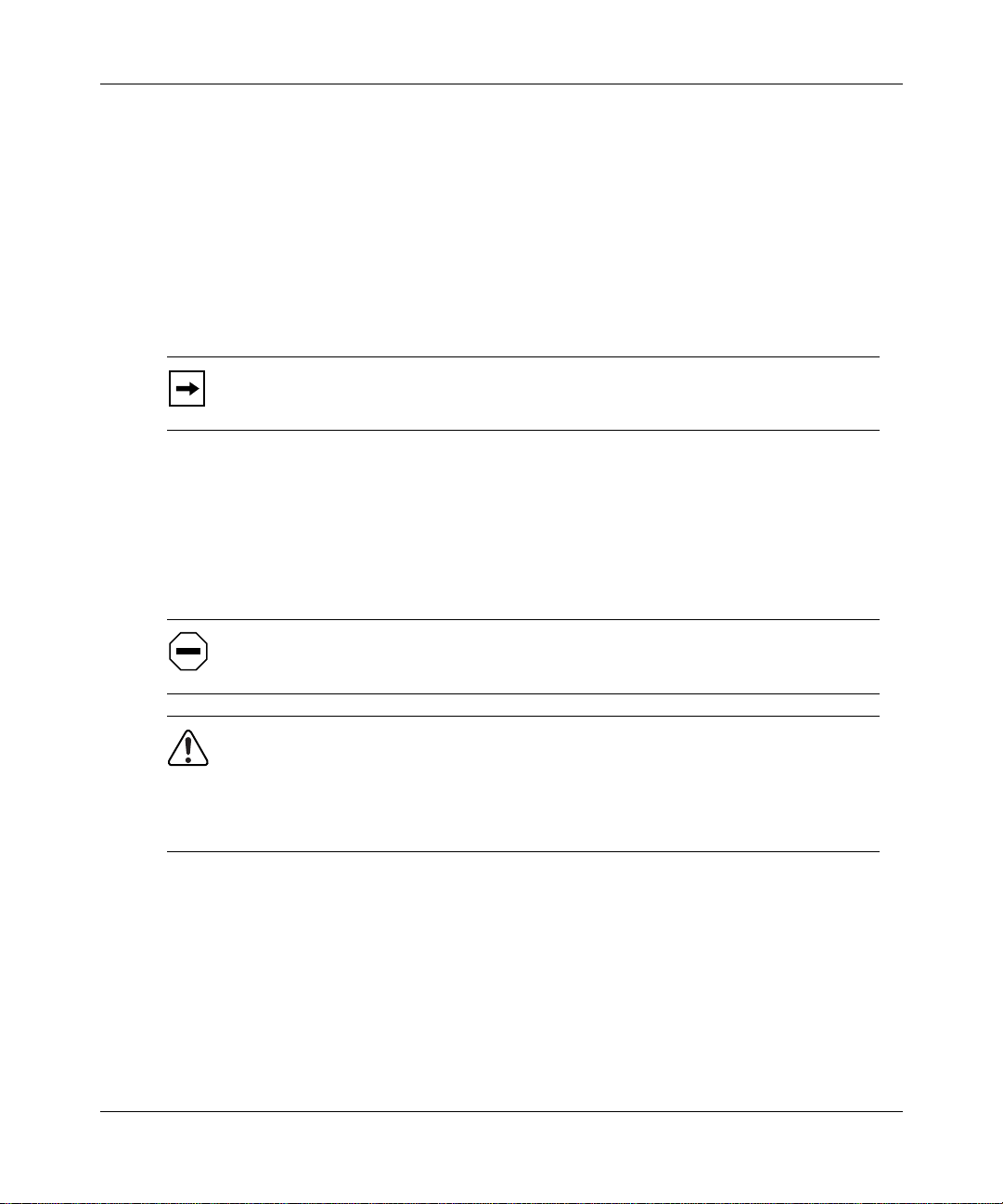
Figure 1-1 shows an intranet and an extranet.
1-1
Page 14
Getting Started with the Contivity Extranet Switch 1500 Series
LAN
NT
Server
Authentication
E-Mail
Server
Server
Intranet
C ontivity
Extranet
Switch
Firewall Router
ISP POP
Internet
ISP POP
Cable or D SL
ISP POP
ISP POP
Modem
ISDN
Reseller
Remote
Employee
Partner
56K
Extranet
Figure 1-1. An Intranet and the Internet Make Up an Extranet
The Switch provides more security than traditional remote access schemes due to
the combination of authorization, authentication, privacy, and access control on a
per user basis. Additionally, the IPsec protocol and related Internet Security
Association & Key Management Protocol (ISAKMP) and the Oakley key
establishment protocol support further enhance the security offering.
1-2
For authentication and access control, the Switch supports an internal or external
Lightweight Directory Access Protocol (LDAP) server and external Remote
Authentication Dial-In User Service (RADIUS) servers.
Page 15
Introducing the Contivity Extranet Switch
To restrict access, the Switch uses packet filtering based on Protocol ID,
Direction, Source and Destin ation IP addresses , Source an d Destinatio n Ports,
and TCP connection establishment. Additionally, Nortel Networks provides
you with a set of predefined filters that you can use either directly or tailor to
your network needs.
The unique quali ty of s ervic e (QoS) me chanis ms inc lude cal l admi ssion
and packet forwar ding priori ties, a nd support for Reso urce ReSer Vation
Protocol (RSVP).
The HTML and Java Web management interface allows different Switch
administrators to have different access rights, including configuration, st atus, and
monitoring. The Switch offers RADIUS accounting support and extensive
logging, including events, system, configuration, and security logs.
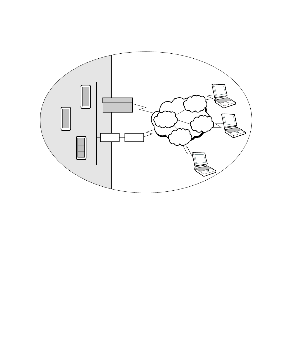
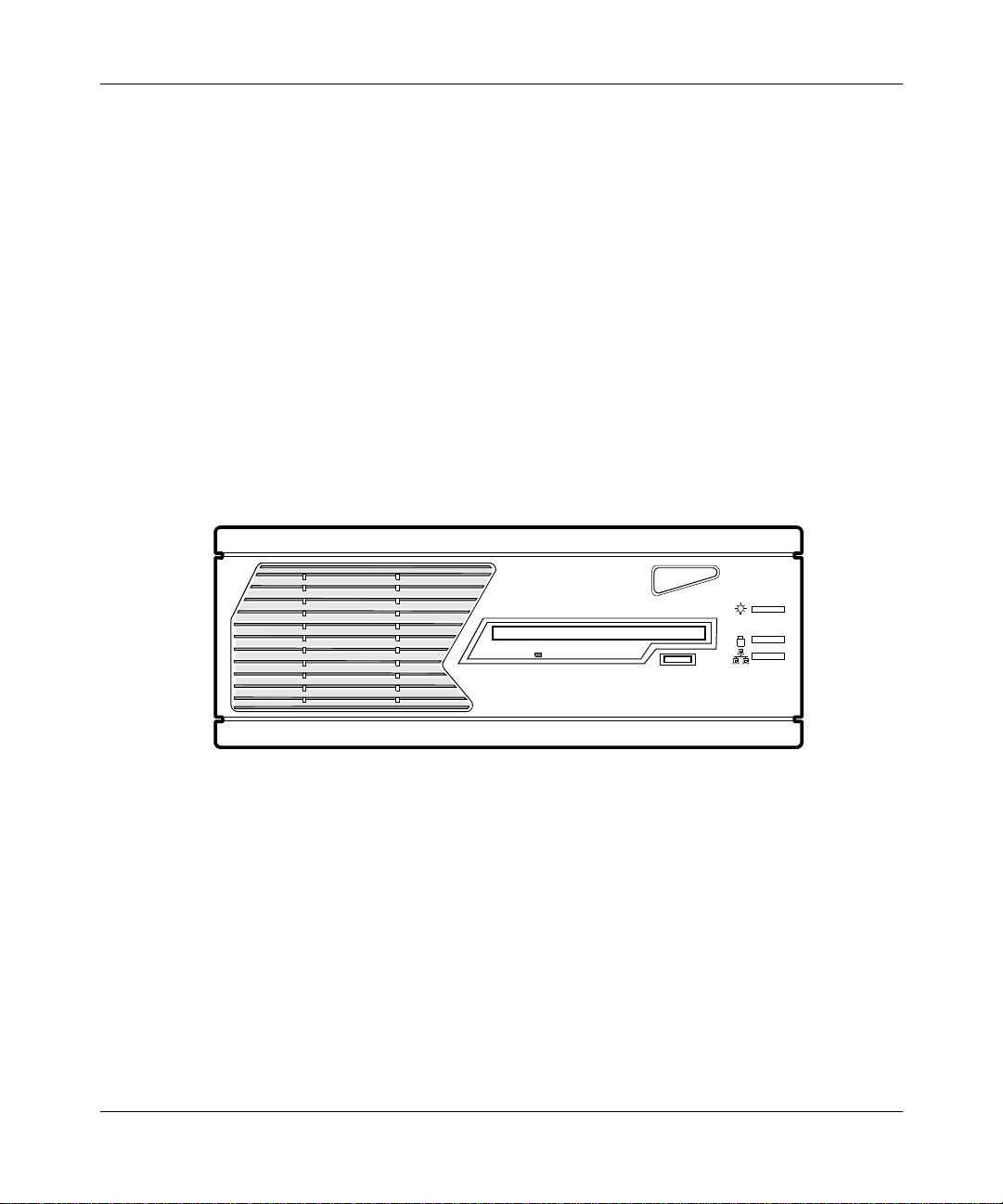
Figure 1-2 shows a front view of the Switch.
Figure 1-2. The Switch, Front View
The Extranet Switch 1500 Series must be placed only in a horizontal position.
1-3
Page 16

Getting Started with the Contivity Extranet Switch 1500 Series
Components List
The following table lists all of the components and accessories of the Switch.
Examine the product packaging to be sure that you have all the necessary
components.
Note that the Extranet Switch 1500 Series has no user-serviceable components.
Description Quantity
Extranet Switch 1500
Power Cord (ordered separately) 0
Molded Serial Cable DB9/DB25-to-DB9/DB25 1
WAN V.35 Cable (only with 1520) 1
Contivity Extranet Switch CD-ROM 1
Recovery Diskette 1
IP Address Configuration Utility Diskette 1
Getting Started Guide (this book) 1
Release Notes 1
Series 1
If for any reason you have not received all of the materials listed above, contact
Nortel Networks Customer Service.
1-4
Page 17

This chapter provides information that you should read before you begin cabling
and configuring the Cont ivity Extranet Switch 1500 Series. This information
includes selecting an appropr iate s ite, sa fety gu ideli nes, informa tion on the po wer
cord, voltage settings, and external vent cooling and airflow recommendations.
Selecting a Site
T
his Switch is designed to operate reliably in a typical office environment. You
should select a site that meets the following criteria:
• Has a desktop or surface that is off the floor.
• Has access to a grounded, three-pronged power outlet.
Chapter 2
Preparing Your Site
- Uses a NEMA 5-15R outlet for 100-120 VAC or a NEMA 6-15R
outlet for 200-240 VAC (US and Canada).
- Uses a three-pronged power outlet that is applicable for the region’s
electrical code (elsewhere).
• Remains dust free and clean.
• Is away from heat sources and is well ventilated.
• Allows adequate cleara nce for cooli ng and airflow -- about 10 cent imeters
(3.93 inches) in back, 5 centimeters (1.96 inches) on each side, and 10
centimeters (3.93 inches) in front.
2-1
Page 18
Getting Started with the Contivity Extranet Switch 1500 Series
Safety Guidelines
Hazardous Conditions Inside the Switch
Hazardous voltage, current, and energy levels are present inside the Switch. Do
not open the Switch; there are no user-serviceable parts inside. Contact Nortel
Networks Customer Support for service.
Switch Power ON/OFF
The On/Off power button on the front panel of the Switch does not completely
eliminate (turn off) the AC power from the Switch. To eliminate AC power from
the Switch completely, unplug the AC power cord from the pow er supply or wall
outlet.
Check the Voltage Switch
WARNING: Incorrectly setting the voltage will damage the
power supply. See Figure 3-1 on page 3-2.
2-2
CAUTION: Make sure that the power service connection is through an
outlet that is properly grou nded.
Before you connect the power cord t o the bac k panel of the Switch , ensure that the
voltage selector switch is correctly set to the appropriate AC line source voltage.
For line voltages between:
• 100 and 127 VAC, set the power supply line voltage selector to
115V (115 VAC).
• 200 and 240 VAC, set the power supply line voltage selector to
230V (230 VAC).
Verify that the correct volta ge ( 1 1 5V or 2 30V) is vi sibl e on the s wit ch. S ee Figur e
3-1 on page 3-2.
Page 19

External Vent Cooling and Airflow
The Switch has external vents for cooling and air flow on:
• The chassis bezel
• The back panel
• On each of the side panels
Keep the side vents clear of obstruction to ensure proper cooling of the Switch.
Preparing Your Site
2-3
Page 20

Page 21

Cabling the Switch
This chapter provides information on the following:
•Cabling
• Local area network (LAN) connections
• Wide area network (WAN ) connections
• Serial interface
• LEDs
For the Contivity Extranet Switch 1500 Series:
• The 1500 and 1510 support connections to LAN interfaces
Chapter 3
• The 1520 supports connections to Single V.35 interfaces
• The 1530 supports connections to T1 CSU/DSU interfaces
Additionally, this chapter cites the LAN/WAN pinouts and the Switch’s LED
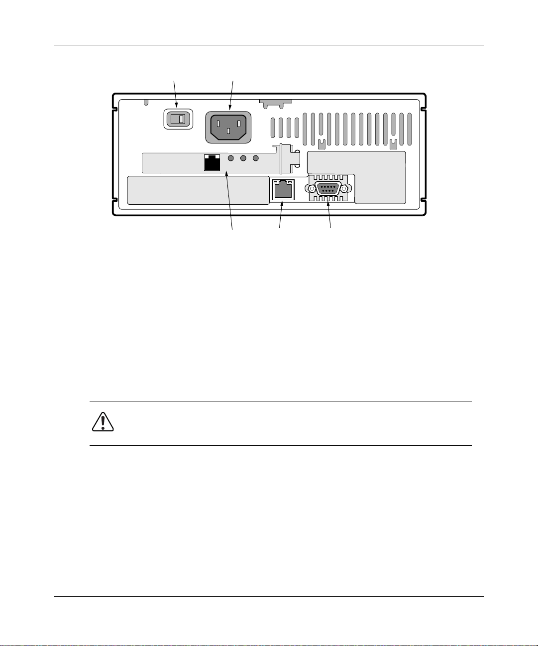
descriptions. Figure 3-1
shows various connector locations.
shows a back view of the Contivity Extranet Switch that
3-1
Page 22
Getting Started with the Contivity Extranet Switch 1500 Series
115/230V
Selector Switch
DATA
Figure 3-1. Extranet Switch Back View
Connecting the Cables
You must connect your cables as follows:
• Connect the power cord to the back of the Switch and to the electrical
outlet.
Power
Connector
ACT
100TX
10/100 BaseT
Card
LNK
LAN
Connector
Serial
Connector
3-2
WARNING: Connect the LAN and serial port cables before you plug the
Switch’s power cord into the out let.
• Connect the LAN/WAN card cables as necessary.
Page 23

Power Cord Requirements
WARNING:
1.
2.
Current Rating
CAUTION: You should protect your Switch by plugging it into a surge
suppressor.
The power cord must be rated for the available AC voltage, and it must have a
current rating which is at least 125 percent of the Switch's current rating. See the
“Physical, Electrical” specifications on page A-1.
Cabling the Switch
Do not modify the AC pow er cord if it is not the exact
type that is required for your power outlet.
Before you connect the power cord to the back panel of
the Switch, ensure that the voltage selector switch is
correctly set to the appropriate AC line source voltage.
See page 2-2.
Wall Outlet Connector
The power cord must be terminated in a male plug with appropriate grounding.
The power cord must have certification marks from an acceptable
regional agency.
Power Supply Connector
The connector that you plug into t he Swit ch power supply AC receptacle must be
an IEC 320, Sheet C13, female.
Cord Length and Flexibility
The power cord must be less than 4.5 meters (14.7 feet) long, and it must be a
flexible HAR (harmonized) cord or VDE-certified cordage to comply with the
Switch's saf ety certifica tions.
3-3
Page 24

Getting Started with the Contivity Extranet Switch 1500 Series
LAN Interface Connections
The LAN interface is avai lable for the Contivity Extranet Switch 1500 and 1510.
There is at least one LAN interface connection, which provides a connection to
the Web for management.
100BASE-TX
100BASE-TX specification supports 100 Mb/s transmission over two pairs
of Category 5 twisted-pair Ethernet wiring; one pair each for transmit and
receive operations.
100 meters is the maximum recommended cable segment length between a
100BASE-TX repeater and a workstation (due to signal timing requirements).
This wiring scheme complies with the EIA 568 wiring standard.
10BASE-T
LAN Speed Selection
The Switch automatically determines the speed of the LAN connection during
power-up. To change the speed, simply power down the unit, connect to the
desired LAN, and power the unit back up.
Connector Pinouts
The LAN connectors on the Switch are RJ-45 straight-through. The following
illustration shows the Switch connector's 10/100BASE-TX pinouts.
RD+ RD- TD+ RD-
connections require Category 5, twisted-pair wire. The
connections can use Category 3, 4, or 5 twisted-pair wiring.
3-4
23456781
Figure 3-2. 10/100BASE-TX Pinouts
Page 25

Single V.35 WAN Interface (Optional)
The Single V.35 WAN connector is located on a PCI card that offers a separate
DB26S connector that pro vides t he si gnals n eed ed to i nterf ace t o V.35 equipment.
Included in the acc essory box is a ca ble that map s the DB26S sig nals t o a standar d
V.35 connector. Table 3-1 shows the cable pinouts.
Table 3-1. DB26S-to-V.35 Cable Pinouts
DB26 Signal V.35
1ShieldA
2TXDAP
3RXDAR
4RTSAC
5CTSAD
6DSRAE
7GNDB
8 DCDA F
9RXCBX
10 DCDB no conn
11 SCTEB W
12 TXCB AA
14 TXDB S
15 TXCA Y
16 RXDB T
17 RXCA V
18 LL L
19 RTSB no conn
20 DTRA H
21 RL N
22 DSRB j
23 DTRB no conn
24 SCTEA U
25 TM NN
Cabling the Switch
3-5
Page 26

Getting Started with the Contivity Extranet Switch 1500 Series
26 M0<-SIGNAL GROUND B
27 M1<-SIGNAL GROUND B
28 M2 no conn
The following notes appl y to the Single V.35 WAN Interface:
• You will need a DSU/CSU (digital service unit/channel service unit)
between the WAN connection and the Switch.
• At each end, Cable shield and connector shell must connect respectively
to pin A of 34-pin connector and pin 1 of the standard 28-pin connector.
• The term “no con n” me ans t he wire i s not connec ted to a pin i n th e 34- pin
connector.
• Wires 12B, 13A, and 14B connect to pin B in the 34-pin connector.
• Unused pins in the 34-pin connector need not be present.
• Do not connect Shield to Signal Ground as these ar e separate signals.
• The pair suffix A or B refers to an individual wire within a twisted pair.
3-6
Page 27

T1 CSU/DSU WAN Interface (Optional)
The T1 CSU/DSU WAN interface is available f or the Contiv ity Extranet Switch
1530. The T1 CSU/DSU WAN crossover cable crosses the blue pair with the
orange pair. This is different from the c ommonly ava ilabl e cros sover cable , which
crosses the green pair with the orange pair. No cables are supplied with the T1
CSU/DSU. Table 3-2 shows the cable pinouts.
Table 3-2. T1 CSU/DSU Cable Pinouts
DB26S Signal T1 CSU/DSU
1 RXDA->TXDA 5
2 RXDB->TXDB 4
3 not used 3
4 TXDB<-RXDB 2
5 TXDA<-RXDA 1
6 not used 6
7 not used 7
8 not used 8
Cabling the Switch
The cable will operate properly if pins 3, 6, 7, and 8 are not connected.
3-7
Page 28

Getting Started with the Contivity Extranet Switch 1500 Series
Serial Interface Cable (Optional)
Nortel Networks recommends that you use the IP Address Configuration Utility
diskette for easy initial IP address configuration (refer to pa ge 4-3 for details).
However, Nortel Networks ships a serial cable with the Switch. Optionally, you
can use the Serial Interfac e to provide t he Switch with a Manag ement IP Address ,
subnet mask, and default gateway address (refer to page 4-2 for details). Later,
you can use the serial interface configuration menu to perform management
functions that you might need if problems were to arise.
The serial cable provided with the Switch is a DB9/DB25-to-DB9/DB25. This
provides a crossover (transmit-to-receive and receive-to-transmit). The DB9
connector goes into t he Swit ch and the othe r DB9 or DB25 conn ector goes into
your workstation. You should ignore the extra DB25 connection that
is attached to the Switch. Table 3-3
serial interface cable pinouts.
Table 3-3. Multi-DB-9 and DB-25 Connector Pinouts
shows the multiple cable DB-9/DB25
Serial Port
DB-9 Connector
Pinout Signal Pinout Signal Pinout Signal Pinout Signal
2 RXD 3 TXD > 2 RXD 3 TXD
3 TXD 2 RXD > 3 TXD 2 RXD
4 DTR 20 DSR > 6 DTR 6 DSR
5 Ground 7 Ground > 7 Ground 5 Ground
6 DSR 6 DTR > 20 DSR 4 DTR
7 RTS 4 RTS > 5 CTS 8 CTS
8 CTS 5 CTS > 4 RTS 7 RTS
Serial Port
DB-25 Connector
Serial Port
DB-25 Connector
Serial Port
DB-9 Connector
3-8
Page 29

Understanding the LEDs
Cabling the Switch
The
Power LED
is green when the power is on; if it is flashing, there is a
hardware failure and you should contact Nortel Networks.
The
Hard Disk LED
is green, and when it flashes the Switch is either reading or
writing to the disk.
The
LAN Port LED
is green, and when i t flas hes the Switch is either transmitt ing
or receiving data.
Start the Switch and confirm that the interfaces are cabled properly by examining
the two LEDs located adjacent to the RJ-45 connector of the LAN port, or the
LEDs located on the card panel.
Figure 3-3 shows the LAN Port LEDs. Look at the condition of the LEDs, then
examine the corresponding LED tables to better understand the indications.
Green
Figure 3-3. LAN Port LEDs
Orange
Table 3-4. LAN Port LED Indicators
LED Indicator Description
Orange On The cable connections between the LAN port
and the hub are good.
Off The cable connections between the LAN port
and the hub are faulty.
On or Flashing The LAN port is sending or receiving network
data. The frequency of the flashes i ncreases
with increased traffic.
Green
(100)
On The LAN port is operating at
100 Mb/s.
Off The LAN port is operating at
10 Mb/s.
3-9
Page 30

Getting Started with the Contivity Extranet Switch 1500 Series
Figure 3-4 shows the Single V.35 LEDs. Look at the condition of the LEDs, then
examine the corresponding LED tables to better understand the indications.
LED 4, Red
LED 3, Green
LED 2, Blue
LED 1, Yellow
Figure 3-4. Single V.35 LEDs
Table 3-5. Single V.35 LED Indicators
LED Description
LED1 Power is on to the adapter and the onboard
microcode is loaded.
LED2 The signals CDC and DSR are on between the
DSU and the adapter. LED2 detects receive
link status.
LED3 Cable is det ected.
LED4 No external transmit clock source is available.
3-10
Page 31

Cabling the Switch
Figure 3-5 shows the T1 CSU/DSU LEDs. Look at the condition of the LEDs,
then examine the corresponding LED tables to better understand the indications.
LED 4, Red
LED 3, Green
LED 2, Blue
LED 1, Yellow
Figure 3-5. T1 CSU/DSU LEDs
Table 3-6. T1 CSU/DSU LED Indicator
LED Description
LED1, Yellow Yellow alarm LED is lit when the far-end
equipment is in the red alarm condition.
LED2, Blue Blue alarm LED is lit when receiving an
upstream failure denoted by an alarm
indication signal (AIS).
LED3, Green Normal operation.
LED4, Red Red alarm is lit w hen a loss of signal (LOS) or
out of frame (OOF) condition is de tected on the
receive signal.
All LEDs off Port disabled.
3-11
Page 32

Getting Started with the Contivity Extranet Switch 1500 Series
Figure 3-6 shows the PCI card 10/100BASE-TX LAN LEDs for the Contivity
Extranet Switch 1510. This does not apply to the 1520 or 1530. Look at the
condition of the LEDs, then examine the corresponding LED table to better
understand the indication s.
LNK
ACT
100
TX
DATA
Link LED
Activity LED
100Mb/s LED
Figure 3-6. 10/100BASE-TX LAN LEDs
Table 3-7. 10/100BASE-TX LAN LED Card Indicators
LED Indicator Description
LNK On The cable connections between the card and
the device to which this interface is attached
are good.
Off The cable connections between the card and
the device to which this interface is attached
are faulty.
ACT On or Flashing The card is sending or receiving network data.
The frequency of the flashes increases with
increased traffic .
Off The card is not sending or receiving data.
100
On Operating at 100 Mb/s.
3-12
TX
Off Operating at 10 Mb/s.
Page 33

Chapter 4
Assigning a System Identity
This chapter describes how to assign a Management IP address, subnet
mask, and optional defaul t gateway address to your Switch. The
Management IP address is used for all system services, such as HTTP, FTP,
and SNMP. The Management IP address enables you to manage the Switch
from a Web browser.
Initial Configuration Options
Table 4-1 describes the choices you have when first
configuring the Switch’s required parameters. The IP Address Configuration
Utility diskette , which c omes wit h your Switch , sear ches f or the seri al nu mbers of
unconfigured Switches. It then displays a table for you to enter the Management
IP address, subnet mask, and default gateway (optional).
To configure the Switch from the serial in terface confi guration menu, you
must first connect the serial interface cable to the Switch. Then you can use a
terminal emulation application to enter the Management IP address, subnet
mask, and default gateway (optional).
Table 4-1. Initial Configuration Options
Initial Configuration
Method Result
IP Address Configuration
Utility (Recommended) Sets Management IP
Serial Interface
Configuration Menu
(Optional)
Address, Subnet Mask,
and Default Gateway
(optional)
Advantages/
Disadvantages
Utility diskette makes
initial configuration easy
Must connect the serial
interface cable
4-1
Page 34

Getting Started with the Contivity Extranet Switch 1500 Series
Startup Configur ation Requirements
This section describes the fields that you must complete
with either the IP Addre ss Configuration Utility or the serial interface
configuration menu procedure.
Management IP Address
Enter a Management IP address for the system. You need this address to manage
all system services, such as HTTP, FTP, and SNMP. This address must be
accessible from one of the Switch's private physical interfaces. Therefore, the
Management IP address must map to the same network as one of the private
interfaces.
For example, if you plan to as sign IP address 10.2.3.3 with Subnet Mask
255.255.0.0 to the private physical interface, then the Management IP address
must reside in the 10.2 network.
Carefully record the Management IP address. Later, during the Quick Start or
the Guided Configuration, you need to supply IP addresses for the physical
interfaces.
Subnet Mask
The Subnet Mask defines how many bits of the IP Address represent the network
the device is on and how many bits represent the host’s ID on the network.
The device uses the Subnet Mask to determine which IP Addresses are directly
reachable on the network and which must be routed through a gateway. A sample
IP Address is 10.2.3.3 with a Subnet Mask of 255.255.0.0. This indicates that all
hosts with addresses 10.2.n.n are directly reachable.
Default Gateway (Optional)
The Default Gateway is where pack ets are rout ed onto the pri vate networ k if there
is not a specific route in the routing table to the desired location.
4-2
Page 35

IP Address Configuration Utility
Use this utility for the initial configuration of a Switch.
Requirements
To assign the Switch a Management IP address, you need:
• A PC running Windows 95® or Windows NT® with a functioning TCP/
IP stack
• The PC running on the same subnet as the Switch you are configuring
• The PC connected to an operational network connection
If your environment does not match these requirements, then you must use the
serial interface configuration.
To test the function of your TCP/IP stack, send a PING command to any host.
Running the IP Configuration Utility
Assigning a System Identity
The program ExtNetIP.exe is on a diskette labeled IP Address Configuration
Utility that acco mpanies th e Switch. You can copy the utility to your hard dis k and
execute it from there, or you can load it from the diskette drive. The ExtNetIP.exe
program launches the IP Address Configuration Utility, which allows you to
assign a Management IP address and subnet mask to the Switch. To run the
configuration utility:
1.
Insert the diskette into the A: drive and select Start→Run:
a:\ExtNetIP.exe
or, open the “My Computer” icon on the desktop and open the “3½
Floppy (A:)” drive, then double-click on the icon:
4-3
Page 36

Getting Started with the Contivity Extranet Switch 1500 Series
The following display appears while the program searches for an
unconfigured Switch.
Figure 4-1. Serial Number Search Display
The program automatically enters the Serial Number for the first available
Switch into the table of Contivity Switches.
4-4
Figure 4-2. IP Address Configuration Utility Display
Page 37

Assigning a System Identity
2.
Assign a Management IP Address and Subnet Mask to the Switch; the
Default Gateway address is optional and you can add it later (see
Startup Configuration Requirements on page 4-2 for descriptions of the
required fields).
If you have more than one Switch, click Search to automatically add the
additional Switch serial numbers. To verify the switches that have been
discovered, you can refer to the serial number on the bar code on the
bottom of the Switch. The serial number on the back of the Switch is that
of the motherboard manufacturer.
3.
Click Apply to configure the Management IP Address, Subnet Mask,
and Default Gateway on the Swit ch. The IP Address Con figuration Utility
screen disappears.
When the Switch updates it s configuration with the Management IP
Address, Subnet Mask, and optional Default Gateway, your default Web
browser automatically opens to the Contivity Extranet Switch Welcome
screen.
4.
Click Close to shut down the IP Address Configuration Utility.
Note:
Before moving the Switch from one network to another, change the
Management IP address, Subnet Mask, and Default Gateway.
Otherwise, you need to follow the Serial Interface Configuration
procedure to access your Switc h because it will not be acce ssible from a
Web browser with an invalid address.
4-5
Page 38

Getting Started with the Contivity Extranet Switch 1500 Series
Serial Interface Configuration
Use the IP Address Configu ration Ut ility (s ee to page 4-3) to co nfigure the Swi tch
with its initial IP address configuration.
Alternatively, you can use the serial interface configuration menu to access
the Switch from the serial interface of your PC. Typically the serial interface
configuration pro cedure is only necessary in a system recovery si t uat ion. The
serial interface configuration menu allows you to give the Switch a
Management IP address, Subnet Mask, and Gateway IP Addres s so that you
can use a Web browser for management.
Prerequisites
The terminal emulator on your PC must use the following
communications parameters:
• 9600 Baud
• 8 Data bits
• 1 Stop bit
4-6
• No Parity
• No Flow Control
Page 39

Procedure
Assigning a System Identity
1.
Connect the serial cable from the Switch’s serial cable port to a terminal or a
PC communications port. It can take the system approximately 3 minutes to
start up.
2.
Using a terminal emulatio n program, s uch as Hyper Terminal, press Enter and
supply a user name and password when prompted. The factory default user
name and password are:
User name:
Password:
admin
setup
A menu appea rs that allows you to enter the following:
• Management IP Address
• IP Subnet Mask
• Gateway IP Address (optional)
• Allow HTTP Management (default)
• Interface IP Address
• Controlled Crash
• Reset to Factory Defaults
3.
Follow the screen prompts. Some of the descriptions of the fields required to
complete this procedure are in the section, “Startup Configuration
Requirements,” on page 4-4-2
Allow HTTP Management
. Other descriptions follow:
enables you to manage the Switch using a
Web browser.
A
Controlled Crash
forces the Swi tch i nto a ha rd cr ash s ta te, whi ch cr eates
a core dump file that Nortel Networks Customer Support can analyze to help
diagnose problems, such as the Switch is hung or it does not respond to
PINGs. Do not select “C) Controlled Crash” unless instructed to do so by
Nortel Networks.
Reset to Factory Defaults
default configuration.
A sample display follows:
returns the Switch to its factory
4-7
Page 40

Getting Started with the Contivity Extranet Switch 1500 Series
Welcome to the Nortel Networks Extranet Switch
Copyright 1998 and 1999, Nortel Networks
Date: 1/29/99
Unit Serial Number: 01001
Please enter the administrator's username: admin
Please enter the administrator's password: setup
1) Management IP Address*
2) IP Subnet Mask
3) Gateway IP Address*
4) Allow HTTP Management
5) Interface IP Address*
C) Controlled Crash
R) Reset to Factory Defaults
E) Exit
*0.0.0.0 resets to factory default value of NULL
Please select a menu choice (1 - 5, C, R, E):
Figure 4-3. Sample Serial Interface Display
4.
After you complete the configuration, type E to Exit. You can then manage
the Switch from a Web browser.
4-8
Important:
This Administ rator's Password is also the Primary Adm inistrator's
Password. This password guarantees access to the Switch from the
serial port or a Web browser.
Page 41

This chapter describes the recommended Web browsers, the default login, and
passwords that you need to access the Nortel Networks Extranet Switch, and the
Quick Start Configuration.
Recommended Web Browsers
Nortel Networks Extranet Manager uses Java, JavaScript, and HTML features.
For the management interface to function properly, verify that your Web browser
meets the following minimum requirements.
Platforms Supported
Chapter 5
Managing the Switch
The Switch supports Windows 95, Windows 98, Windows NT, and Macintosh®
operating systems.
Browser Versions
The Switch supports the following Web browsers:
• Microsoft Internet Explorer--Version 4.0 or later is required.
• Netscape Communicator--Version 4.0 or later is required.
Display Setting
Verify that the system display color setting is 256 colors or greater.
5-1
Page 42

Getting Started with the Contivity Extranet Switch 1500 Series
Preparing for Configuration
To properly prepare for Installation and Configuration of the Contivity Extranet
Switch, you should have the following:
• A Management IP Address for the system. You need this address to
manage all system services, such as HTTP, FTP, and SNMP.
• An IP Address for the LAN port that is available on the system board.
• Any number of Publi c IP Address es; f or ex ample, o ne IP add ress for e ach
Public LAN/WAN Interface.
• A plan to distribute IP addresses to clients when connections are
requested; for example, us ing a DHCP server or an interna l clie nt addre ss
pool (with an address pool you need a range of IP addresses).
• An Authentication database. If you are not using internal authentication
with the LDAP database, be sure you have either the external LDAP or
the RADIUS server IP Address and password or Shared Secret
(password).
• An external accounting server, such as RADIUS, with its IP Address and
Shared Secret (password).
5-2
• Client dial-in. Prepare the clients for the type of tunneling protocol they
plan to use. The PPTP client application is available for Windows 95 on
the Nortel Networks CD, and it comes with the Windows 98 and
Windows NT ope rati ng syst ems. No rtel Networks also p rovide s the IP sec
client on the Nortel Networks CD.
• A complete network topology of the en vironment in which you ar e testing
the Switch, including th e Switch, the default r outer addres s, and any othe r
IP addresses that might be required.
Page 43

Extranet Switch Welcome Display
The Welcome screen allows you to enter any of the configuration areas for the
Extranet Switch, includin g:
• Quick Start Configuration
• Guided Configuration
• Manage Extranet Switch
• Registration
•Notebook
Before entering the configuration options, you should first register to activate
licenses, warranties, and services.
The alternatives you have when first configur ing your Switch are shown in
Table 5-1
the Guided Configuration. Once you are familiar with the Switch’s navigation
menu and capabilities, then you can select Manage Extranet Switch.
Table 5-1. Configuration Alternatives
. Nortel Networks recommends that you begin with the Quick Start or
Managing the Switch
Configuration Type Results
Quick Start Configure and Test a basic PPTP
configuration
Guided Structured Switch configuration and
management
Manage Comprehensive Switch con figuration and
management
Following is a sample Ext ranet Switch Welcome display, fo llowed by descrip tions
of each configuration option. A detailed checklist describes what you need to
properly configure your Switch, followed by full details of the different
procedures.
Complete det ails for configuring and monitoring the Switch are in the Nortel
Networks Contivity Extranet Switch Administrator's Guide.
5-3
Page 44

Getting Started with the Contivity Extranet Switch 1500 Series
5-4
Figure 5-1. Switch Welcome Display
Page 45

Quick Start
Click to begin the Quick St ar t Con fi gur at ion. This option allows you to configure
interfaces, set up PPTP tunnels for up to three use rs, and establish a connection to
the Switch. Provided you have the information required to set up the Switch, the
Quick Start c an take as litt le as 15 minutes to complete.
Guided Configuration
Click to begin the Guided Configuration. This option allows access to all
Configuration Management facilities. However, the design and structure of the
Guided Configuration is best followed using the top-to-bottom layout provided.
This approach walks you through the entire Navigational Menu from the Profiles
to the Status selections.
Each functional area begins with a summary of the objectives and then steps you
through the area (such as, Profiles), one subsection at a time.
Online cont ext-sensitiv e Help is available for each subsection.
Provided you have the information required to set up the Switch, the Guided
Configuration can to take two to three hours to complete, depending on whether
your configuration is simple or more complicated.
Managing the Switch
Manage Extranet Switch
Click to begin a standard configuration and management session. This option
allows access to all configuration management facilities. You should follow the
Quick Start or Guided Conf iguration for your first configuration.
Registration
Click to register the Switch with Nortel Networks. This only take a few minutes
and gives you access to the latest software and technical tips. Your Switch
requires Internet access in order to register.
Notebook
Click to activate the notebook display mode. The Contivity Extranet Switch
Manager then runs in noteboo k display mode, which better fits notebook displays.
5-5
Page 46

Getting Started with the Contivity Extranet Switch 1500 Series
Logging in and Supplying a Password
Start up a Web browser and enter your Switch's Management IP Address. Select
an option in the navigational menu and submenu. When you are prompted for the
Login and Password, enter the system default Login and Password in lowercase
letters, as f ollows:
Login: admin
Password: setup
IMPORTANT:
If you change your password and later need to access the Serial
Interface Configuration, you must enter the modified password.
The factory default password is no longer valid in this case. Also,
make sure you change the default Administrator's Login and
Password as soon as possible (refer to the Admin→Administrator
display). You should then guard the Login and Passwor d careful ly.
The password is case sensitive.
5-6
Page 47

Quick Start Configuration Pr erequisites
This screen acts as a check list fo r you t o prepare for the Qu ick Start confi guratio n.
Assembling the information beforehand, and verifying that you can establish a
PPTP Client session, makes Quick Start easy.
Managing the Switch
Figure 5-2. Quick Start Prerequisites Display
5-7
Page 48

Getting Started with the Contivity Extranet Switch 1500 Series
Required Environment
This section describes the environment that you need for the Quick Start
Configuration. If this does not describe your environment, use the Guided
Configuration.
Point-to-Point Tunnel Protocol (PPTP) tunnel access method
PPTP is a tunneling protocol supported by Nortel Networks, Microsoft, and other
vendors. The PPTP client is available for W indows 95 on the Norte l Networks CD
and comes with Windows 98 and Windows NT 4.0 and later operating systems.
Static IP addresses, Dynamic Host Configuration Protocol (DHCP)
server address allocation, or an Internal Client Address Pool
A DHCP Server on the private LAN segment dyna mically as signs IP a ddresses on
behalf of remote users. The DHCP server is automatically discovered by
broadcasting on the private interface that is associated with the Management IP
Address. With an Internal Client Address Pool, you need a range of IP addresses.
Local Lightweight Directory Access Protocol (LDAP) database authentication
5-8
LDAP is a standard protocol for Internet directory services that is based on
directory entries. A directory service is a central repository of user information.
The local database is internal to the Switch.
The Switch for the Quick Start procedure sets up an LDAP server and associated
database locally. Later, you can switch to a network-available external LDAP
server using the LDAP Intermediate File (LDIF) data format.
Page 49

Prerequisites
You must meet the following prerequisites:
• IP configuration information (refer to Startup Configuration
Requirements on page 5-7 for additional information):
- Management IP Address for the Switch
- Subnet Mask for the local subnet
• User IDs and Passwords:
- PPTP Users (up to three)
- Administrator
Post Configuration Testing
To test your configuration, verify that a PPTP remote user can dial in from an
external system.
Refer to the Contivity Extranet Switch Administrator's Guide, th e Switch’s online
help, and the Microsoft PPTP documentation for additional information.
Managing the Switch
5-9
Page 50

Getting Started with the Contivity Extranet Switch 1500 Series
Configuration
This screen allows you to add a LAN port IP Address and Subnet Mask,
establish the tunnel as Private (your private LAN) or Public (public data
networks), and configure up to three PPTP Users and an Administrator with
User IDs and Passwords. You can also set the system's date and time. The
following figure show partial displays of the Quick Start Configuration screen.
5-10
Figure 5-3. Quick Start Configuration Display
Page 51

LAN/WAN Interfaces
Interfaces
Lists the Management IP Address, LAN/WAN port, and LAN card.
IP Address
Enter an IP address for each interface on the Switch, includi ng the LAN port. The
Switch uses these IP addresses for tunnel creation. The IP Address consists of 32
bits, which are written as four octets in dotted-decimal format as fo llows:
192.168.34.21
You must supply the interface IP Address configuration information, not the
Management IP Address that you already configured through the initial IP
Address configuration.
Subnet Mask
The Subnet Mask defines how many bits of the IP Address represent the network
the device is on and how many bits represent the host’s ID on the network.
Managing the Switch
The device uses the Subnet Mask to determine which IP Addresses are directly
reachable on the network and which are only reachable through a gateway. A
sample IP Address is 10.2.3.3 with a Subnet Mask of 255.255.0.0. This indicates
that all hosts with addresses 10.2.n.n are directly reachable.
Default Gateway
If the routing table contains no specific route to the desired location, the Default
Gateway packets are routed onto the private network.
Type
The default configuration assigns the Management LAN interface as Private and
the LAN card interface as Public.
5-11
Page 52

Getting Started with the Contivity Extranet Switch 1500 Series
Public
Indicates that this interface is attached to a Public data network like the
Internet. On a Public interface, the Switch rejects non-tunneled protocols and
accepts only tunneled protocols, such as IPsec, PPTP, L2TP, L2F and the
diagnostic protocol PING.
A host can send only enough packets to a Public interface to establish a tunnel
connection. If the tunnel i s not esta blish ed before the prese t maximum-numbe r-of
packets-allowed coun ter is reached, t hen the Switc h discar ds the packe ts from t hat
host.
Private
Indicates that this i nterfac e is attached to the Private netwo rk and that it can accept
non-tunneled networking protocols such as TCP/IP, FTP, and HTTP. The Private
interface also accepts tunneled protocols (such as IPsec, PPTP, L2TP, and L2F)
that can be used for secure management access to the Switch.
PPTP Users
5-12
User ID
Enter a User ID. The User ID works al ong with the pass word as the au thentica tion
mechanism when attempting to access your local LAN through the Switch.
Password
Enter a user Password. You should use a minimum of eight characters, including
upper and lowercase letters and numbers . Avoid using common names and words
found in the dictionary. For example, a password constructed as “AxSessPw4U”
is much better than “dog” or “Barne y.”
Note:
Do not use a password of 16 pound signs (#).
Page 53

Confirm Password
Reenter the assigned password to verify that you have typed the intended
password correctly.
Remote User Static IP Address
Enter an IP Address to be assigned to this user when establishing a PPTP tunnel
session. This IP Address is unnecessary if you assign user IP addresses from
either a DHCP server or an internal address pool.
Administrator
The Administrator Settings allow you to change the Primary Administrator User
ID (UID) and Password. The Primary Administrator User ID and Password
combination always has access to all displays and controls. You can also use this
UID to access the serial port. There can be only one Primary Administrator.
User ID
Enter an app ropriate User ID for the Primary Administra tor. This UID has the
privileges to modify and view all controls in the Switch.
Managing the Switch
Password
Enter a user P assword for the Primary Admi nistrator.
Note:
Do not use a password of 16 pound signs (#).
Confirm Password
Reenter th e assigned password for the Primary Administrator to verify that you
have typed the intended password correctly.
5-13
Page 54

Getting Started with the Contivity Extranet Switch 1500 Series
Date and Time
Date
Enter the current month, day, and year (mm/dd/yyyy).
Time
Enter the current hour, minute, and seconds (hh:mm:ss) as displayed by a 24-h our
clock (00:00:00 to 23:59:59).
Automatic Backup
The Automatic Backup scr een under the Manage configuration option allows you
to configure regula r i ntervals when your system files are saved to desig nat ed hos t
backup file servers.
IMPORTANT: You should configure Automatic Backups immediately so
that you do not lose system or configuration information in
case of problems.
5-14
You configure the Automatic Backup servers from the Admin→Automatic
Backup display.
Page 55

Windows 95
T o inst all the No rtel Netwo rks Extranet Access Cli ent onto a Windows 95 PC,
you must copy and load the four fil es that a re on t he Nortel Networks Extranet
CD in the Client folder onto your hard drive. International software users
must go to the Microsoft Web site (http://support.microsoft.com/support) to
get the MSDUN13 patch.
1.
Chapter 6
Extranet Access Client Installation
First, install Msdun12.exe (Microsoft Dial-up Networking update) by
double-clicking on the file name. The installation is self-explanatory. You
might need your Windows 95 CD (in case the CD was not copied onto your
drive). During the installation you will be asked to reboot your system twice.
2.
Next, install Wsockupd.exe (Winsock update) if you are using the retail
version of Windows 95. Reboot your system after installing the update. You
now have the Microsoft PPTP tunneling client installed.
3.
Complete the IPsec installation by running the Eac_20d.exe, (Nortel
Networks Extranet Access Client). The installation is self-explanatory. You
might need your Windows 95 CD-ROM (in case the CD was not copied onto
your drive). When prompted at the end of the inst al lat i on, r eboot your system.
4.
If you do not care about operating within the Network Neighborhood, skip
this step. To operate within the Network Neighborhood, enable the following
items under the Network Control Panel (click the Start menu button, select
Settings→Control Panel, then double-click on the Network icon to open the
Network Control Panel).
6-1
Page 56

Getting Started with the Contivity Extranet Switch 1500 Series
a.
Under the box titled “The following network compon ent s are ins ta ll ed,”
verify that the Client for Microsoft Networks is l ist ed . If it is not, click on
the ADD button, then select CLIENT, then click the ADD button again.
Select Microsoft followed by Client for Microsoft Networks and finally
the OK button. You will need your Windows 95 CD if it is not already
copied onto your system.
b.
Under the same box titled “The following network components are
installed,” make sure that NetBEUI is not installed. To verify this, scroll
down through the list box and look for any lines that have NetBEUI in
them. If there are any lines that include NetBEUI, click on the line,
and then click on the Remove button. This forces the Network
Neighborhood to use NetB IOS over TCP/IP, which is compatible with the
Extranet Switch.
c.
Under the Identity tab, configure the Workgroup to be the same as your
company’s internal workgroup. For example, “Nortelnetworks.”
d.
Next under th e Identity ta b, verify that the Computer Name is different
from your PC at work. Otherwise, you would be attempting to log a
second unit with the same name onto the network.
e.
If you have made any changes in the Network Control Panel, click OK
and then reboot the system.
6-2
f.
Double-click on the Extranet Connection Manager icon.
g.
Enter a new Connection Profile Name.
h.
Create a new Dial-up Connection.
i.
Click the Tool button (next to the Dial-up Connection list box), select
New, and follow the wizard.
j.
Create a new Extranet Connection.
k.
Click the Tool button (next to the Extranet Connection list box), select
New IPsec Connection, and follow the wizard.
l.
Click the Connect button.
Page 57

Windows 98 and Windows NT 4.0
To install the Nortel Networks Extranet Access Client onto a Windows 98 PC or
Windows NT 4.0 workstation, you must copy the Extranet Access Client
(Eac_20d.exe) that is on the Contivity Extranet Switch CD in the Client fold er
onto your hard drive.
1.
Install Eac_20d.exe by double-clicking on the program name. The
installation is self-explanatory. When prompted at the end of the installation,
reboot your system.
2.
If using the Extranet Access Client over a dial-up connection:
Windows NT: Install the Remote Access Service under the Network Control
Panel (from the Start menu, select Settings→Control Panel, then double-click
on the Network icon to open the Network Control Panel). Select the Services
tab and click on Add. Scroll down to select “Remote Access Service” and
click on OK.
Windows 98: Under the Network Control Panel (from the Start menu,
select Settings→Control Panel), select Add→Adapter→
Microsoft→Dial-up Adapter.
Extranet Access Client Installation
3.
Under the Protocols tab f or Windows NT or under the Network Control Panel
for Windows 98, verify that NetBEUI is not installed. If NetBEUI is listed,
click on it, then click on the Remove button. This will force the Network
Neighborhood to use NetBIOS over TCP/IP, which is compatible with the
Switch. Click on the OK button and reboot your system.
4.
Double-click on the Extranet Connection Manager icon.
a.
Enter a new Connection Profile Name.
b.
Create a new Dial-up Connection.
c.
Click on the Tool button (next to the Dial-up Connection list box), select
New, and follow the wizard.
d.
Create a new Extranet Connection.
e.
Click on the Tool button (next to the Ex tr anet Connection list box), select
New IPsec Connection, and follow the wizard.
f.
Click on the Connect button.
6-3
Page 58

Page 59

Physical
Depth: 13 in. (33.02 cm)
Width: 9.5 in. (24.13 cm)
Height: 3.5 in. (8.89 cm)
Weight: 10.0 lbs (4.539 kg)
Electrical: 110-127V, 2.0A; 200-240V, 1.25A 50-60Hz
Appendix A
Specifications and Compliance
Operating Environment
Temperature: 50°F-95°F (10°C-35°C)
Relative Humidity: 10%-90% non-condensing
Declaration of the Manufacturer or Imp orter
Nortel Networks hereby certifies that this product is in compliance with EU EMC
Directive 89/336/EEC, using standards EN55022 Class B and EN50082-1, and
the Low Voltage Directive 73/23/EEC via standard EN60950.
Additional c ompliance in formation is in Appendix B, Sp ecial Notices.
A-1
Page 60

Getting Started with the Contivity Extranet Switch 1500 Series
Safety Compliance
: UL 1950, 3rd Edition
USA
Canada
Europe
International
: UL certified to CSA C22.2 No. 950-95 for Canada
: TUV to EN60950 2nd Edition, with amendments
: NEMKO to IEC950 (A1 + A2 + A3)
NEMKO to EN60950 (A1 + A2 + A3)
NEMKO to EMKO-TSE(74-SEC) 207/94
Electromagnetic Compatibility (EMC)
: FCC CFR 47 Part 15, Tested Class B
USA
Canada
Europe
: IC ICES-003 Class B
: EN55022, Class B
EN 61000-3-2, 95
EN50082-1
- IEC 801-2 ESD Susceptibility
- IEC 801-3 Radiated Immunity
Harmonics
A-2
- IEC 801-4 Electrical Fast Transient
International
Japan
Europe
Japan
and General-Use Equipment, 1995 (or meet exception criteria of <75W AC
input power).
: VCCI Class B ITE
: MITI Guideline for the Suppression of High Harmonics in Household
: CISPR 22/93, Class B
: EN 61000-3-2, 1995
Page 61

Appendix B
Special Notices
This appendix provides information on statements of conditions, the Nortel
Networks Software License Agreement, and RADIUS attribution.
Statement of Conditions
In the interest of impr oving inte rnal design, operation al functio n, and/o r reliabil ity , Nortel Netw orks,
Inc. reserves the right to make changes to the products described in this document without notice.
Nortel Networks, Inc. does not assume any liability that may occur due to the use or application of
the product(s) or circuit layout(s) described herein.
Portions of the code in this software product may be Copyright © 1988, Regents of the University of
California. All rights reserved. Redistribution and use in source and binary forms of such portions
are permitted, provided that the above copyright notice and this paragraph are duplicated in all such
forms and that any documentation, advertising materials, and other materials related to such
distribution and use acknowledge that such porti ons of the software were developed by the
University of California, Berkeley. The name of the University may not be used to endorse or
promote products derived from such portions of the software without specific prior written
permission.
SUCH PORTIONS OF THE SOFTWARE ARE PROVIDED “AS IS” AND WITHOUT ANY
EXPRESS OR IMPLIED WARRANTIES, INCLUDING, WITHOUT LIMITATION, THE
IMPLIED WARRANTIES OF MERCHANTABILITY AND FITNESS FOR A PARTICULAR
PURPOSE.
In addition, the pr ogram and information contained herein are licensed only purs uant to a license
agreement that contains restrictions on use and disclosure (that may incorporate by reference certain
limitations and notices imposed by third parties).
B-1
Page 62

Getting Started with the Contivity Extranet Switch 1500 Series
Federal Communications Commission (FCC) Compliance Notice: Radio Frequency Notice
Note: This equipment has been tested and found to comply with the limits for a Class A digital
device, pursuant to Part 15 of the FCC rules. These limits are designed to provid e reasonable
protection against harmful int erference when the equipment is operated in a commercial
environment. Thi s equipment generates, uses, and can radiate radio frequency e nergy. If it is not
installed and used in accordance with the instruction manual, it may cause harmful interference to
radio communications. Operatio n of this equipment in a residential area is likely to cau se harm ful
interference, in which case users will b e required to take whatever measures ma y be necessary to
correct the interference at their own expense.
EN 55 022 Statement
This is to certify that the Nortel Netwo rks Co nt ivity Extranet Switch 1500 Series is shielded against
the generation of radio interference in accordance with the application of Council Directive 89/336/
EEC, Article 4a. Conformity is declared by the application of EN 55 022 Class A (CISPR 22).
Warning: This is a Class A product. In a domestic environment, this pro duc t may cause radio
interference, in which case, the user may be required t o t ake appropriate measures.
EC Declaration of Conformity
This product conforms (or these products conform) to the provisions of Council Directive 89/336/
EEC and 73/23/EEC. The Declaration of Conformity is available on the Nortel Networks Wo rld
Wide Web site at www.nortelnetworks.com.
B-2
Voluntary Control Council for Interference (VCCI) Statement
This is a Class A product based on the standard of the Voluntary Control Council for
Interference by Information Technology Equipment (VCCI). If this equipment is used in a
domestic environment, radio disturbance may arise. When such trouble occurs, the user may be
required to take corrective actions.
Page 63

Special Notices
Canadian Department of Communications Radio Interference Regulations
This digital apparatus, the Contivity Extranet Switch 1500 Se ries, does not exceed the Class A limits
for radio-noise emissions from digital apparatus as set out in the Radio Interference Regulations of
the Canadian Department of Communicati ons.
Règlement sur le brouillage radioélectriqu e du ministère des Communications
Cet appareil numérique, le Contivity Extranet Switch 1500 Series, respecte les limites de bruits
radioélectriques visant les appareils numériques de classe A prescrites dans le Règlement sur le
brouillage radioélectrique du ministère des Communications du Canada.
Nortel Networks NA, Inc. Software License Agreement
NOTICE: Please carefully read this license agreement before co pying or using the accompa nying
software or installing the hardware unit with pre-enabled software (each of which is referred to as
“Software” in this Agreement). BY COPYING OR USING THE SOFTWARE, YOU ACCEPT ALL
OF THE TERMS AND CONDITIONS OF THIS LICENSE AGREEMENT. THE TERMS
EXPRESSED IN THIS AGREEMENT ARE THE ONLY TERMS UNDER WHICH NORTEL
NETWORKS WILL PERMIT YOU TO USE THE SOFTWARE. If you do not accept these terms
and conditions, return the product, unused and in the original shipping container, within 30 days of
purchase to obtain a credit for the full purchase price.
1. License Grant. Nortel Networks, Inc. (“Nortel Networks”) grants the end user of the Software
(“Licensee”) a personal, nonexc lusive, nontransferable license: a) to use the Software either on a
single computer or, if applicable, on a single authorized device identified by host ID, for which it
was originally acquired; b) to copy the Software solely for backup purposes in support of authorized
use of the Software; and c) to use and copy the associated user manual solely in support of
authorized use of the Software by Licensee. This license applies to the Software only and does not
extend to Nortel Netw or ks Agent software or other Nortel Networks software products. Nortel
Networks Agent software or other Nortel Networks software products are licensed for use under the
terms of the applicable Nortel Networks, Inc. Software License Agreement that accompanies such
software and upon payment by the end user of the applicable license fees for such software.
B-3
Page 64

Getting Started with the Contivity Extranet Switch 1500 Series
2. Restrictions on use; reservation of rights. The Software and user manuals are protected under
copyright laws. Nortel Networks and/or its licensors retain all title and ownership in both the
Software and user manuals, including an y revisions made by Nortel Networks or its licensors. The
copyright notice must be reproduced an d included with any copy of any portion of the Sof tware or
user manuals. Licensee may not modify, translate, decompile, disassemble, use for any competitive
analysis, reverse engineer, distribute, or cr eate derivative works from the Software or user manuals
or any copy, in whole or in part. Except as expressly provided in this Agreement, Licensee may not
copy or transfer the Software or user manuals, in whole or in part. The Software and user manuals
embody Nortel Networks’ and its licensors’ confidential and proprietary intellectual property.
Licensee shall not sublicense, assign, or ot herwise disclose to any third party the So ftware, or any
information abou t the operation, design, performance, or i mplementation of the Software and user
manuals that is confidential to Nortel Networks and its licensors; however, Licensee may grant
permission to its consultants, subcontractors, and agents to use the Software at Licensee ’s facility,
provided they have agreed to use the Software only in accordance with the terms of this license.
3. Limited warranty. Nortel Networks warrants each item of Software, as delivered by Nortel
Networks and properly installed and operated on Nortel Networks hardware or other equipment it is
originally licensed for, to function substantially as described in its accompanying user manual
during its warranty period, which begins on the date Software is first shipped to Licensee. If any
item of Software fails to so function during its warranty period, as the sole remedy Nortel Networks
will at its discretion provide a suitable fix, patch, or workaround for the problem that may be
included in a future Software release. Nortel Networks further warrants to Licensee that the media
on which the Software is provided will be free from defects in materials and workmanship under
normal use for a period of 90 days from the date Software is first shipped to Licensee. Nortel
Networks will replace defective media at no charge if it is returned to Nortel Networks during the
warranty period along with proof of the date of s h ipm e nt. This warranty does not appl y if the media
has been damaged as a result of acci dent, misuse, or abuse. The License e assumes all responsibility
for selection of the Software to achieve Licensee’s intended results and for the installation, use, and
results obtained from the Software. Nortel Networks does not warrant a) that the functions contained
in the software will meet the Licensee’s requirements, b) that the Software will operate in the
hardware or software combinations that the Licensee may select, c) that the operation of the
Software will be uninterrupted or error free, or d) that all defects in the operation of the Software
will be corrected. Nortel Networks is not obligated to remedy any Software defect that c a nnot be
reproduced with the latest Software release. These warranties do not apply to the Software if it has
been (i) altered, except by Nortel Networks or in accordance with its in structions; (ii) used in
conjunction with another vendor’s product, resulting in the defect; or (iii) damaged by improper
environment, abuse, misuse, accident, or negligence. THE FOREGOING WARRANTIES AND
LIMITATIONS ARE EXCLUSIVE REMEDIES AND ARE IN LIEU OF ALL OTHER
WARRANTIES EXPRESS OR IMPLIED, INCLUDING WITHOUT LIMITATION ANY
WARRANTY OF MERCHANTABILITY OR FITNESS FOR A PARTICULAR PURPOSE.
Licensee is responsible for the security of its own data and information and for maintaining adequate
procedures apart from the Software to reconstruct lost or altered files, data, or programs.
B-4
Page 65

Special Notices
4. Limitation of liability. IN NO EVENT WILL Nortel NETWORKS OR ITS LICENSORS BE
LIABLE FOR ANY COST OF SUBSTITUTE PROCUREMENT; SPECIAL, INDIRECT,
INCIDENTAL, OR CONSEQUENTIAL DAMAGES; OR ANY DAMAGES RESULTING
FROM INACCURATE OR LOST DATA OR LOSS OF USE OR PROFITS ARISING OUT OF
OR IN CONNECTION WITH THE PERFORMANCE OF THE SOFTWARE, EVEN IF Nortel
NETWORKS HAS BEEN ADVISED OF THE POSSIBILITY OF SUCH DAMAGES. IN NO
EVENT SHALL THE LIABILITY OF Nortel NETWORKS RELATING TO THE SOFTWARE
OR THIS AGREEMENT EXCEED THE PRICE PAID TO Nortel NETWORKS FOR THE
SOFTWARE LICENSE.
5. Government Licensees. This provision applies to all Software and documentation acquired
directly or indir ectly by or on behalf of the United States Government. The Software and
documentation are commerc ial products, licensed on the open market at market prices, and were
developed entirely at private expense and without the use of any U.S. Government funds. The
license to the U.S. Government is granted only with restricted rights, and use, duplic ation, or
disclosure by the U.S. Government is subject to the restrictions set forth in subparagraph (c)(1) of
the Commercial Computer Software––Restricted Rights clause of FAR 52.227-19 and the
limitations set out in this license for civilian agencies, and subparagraph (c)(1)(ii) of the Rights in
Technical Data and Computer Software clause of DFARS 252.227-7013, for agencies of the
Department of Def en s e or the ir su c ce s sors, whichever is applicable.
6. Use of Software in the European Community. This provision applies to all Software acquired
for use within the European Community. If Licensee uses the Software within a country in the
European Community, the Software Directive enacted by the Council of European Communities
Directive dated 14 May, 1991, will apply to the examination of the Software to facilitate
interoperability. Licensee agrees to notify Nortel Networks of any such intended examinatio n of th e
Software and may procure support and assistance from Nortel Networks.
7. Term and termination. This license is effective until terminated; however, all of th e restrictions
with respect to Nortel Networks’ copyright in the Software and user manuals will cease being
effective at the d ate o f e xpira tio n of th e Nort el Network s c opy r ight; those restrictions relating to use
and disclosure of Nortel Networks’ confidential information sh all continue in effect. Licensee may
terminate this license at any time. The license will automatically terminate if Licensee fails to
comply with any of the terms and conditions of the license. Upon termination for any reason,
Licensee will immediately destroy or return to Nortel Networks the Software, user manuals, and all
copies. Nortel Networks is not liable to Licensee for damages in any form solely by reason of the
termination of this license.
8. Export and Re-export. Licensee agrees not to export, directly or indirectly, the Software or
related technical data or informatio n wi tho ut first obtainin g any requ ired exp ort lic ense s or othe r
governmental approv als. Without limiting the foregoing, Licensee, on behalf of itself and its
subsidiaries and affiliates, agrees that it will not, without first obtaining all export licenses and
approvals required by the U.S. Government: (i) export, re-export, transfer, or divert any such
Software or technical data, or any direct product thereof, to any country to which such exports or
re-exports ar e re str icted or e mba rg o ed un der U nited Stat es ex p ort con tro l law s and r egu latio ns, o r to
any national or resident of such restricted or embargoed countries; or (ii) provide the Software or
related technical data or information to any military end user or for any military end use, including
the design, development, or producti on of any chemical, nuclear, or biological weapons.
B-5
Page 66

Getting Started with the Contivity Extranet Switch 1500 Series
9. General. If any provision of this Agreement is held to be invalid or unenforceable by a court of
competent jurisdiction, the remainder of the provisions of this Agreement shall remain in full force
and effect. This Agreement will be governed by the laws of the state of California.
Should you have any questions concerning this Agreement, cont act Nortel Networks, Inc., 4401
Great America Parkway, P.O. Box 58185, Santa Clara, California 95054-8185.
LICENSEE ACKNOWLEDGES THAT LICENSEE HAS READ THIS AGREEMENT,
UNDERSTANDS IT, AND AGREES TO BE BOUND BY ITS TERMS AND CONDITIONS.
LICENSEE FURT HER AGREES THAT THIS AGREEMENT IS THE ENTIRE AND
EXCLUSIVE AGREEMENT BETWEEN Nortel NETWORKS AND LICENSEE, WHICH
SUPERSEDES ALL PRIOR ORAL AND WRITTEN AGREEMENTS AND
COMMUNICATIONS BETWEEN THE PARTIES PERTAINING TO THE SUBJECT MATTER
OF THIS AGREEMENT. NO DIFFERENT OR ADDITIONAL TERMS WILL BE
ENFORCEABLE AGAINST Nortel NETWORKS UNLESS Nortel NETWORKS GIVES ITS
EXPRESS WRITTEN CONSENT, INCLUDING AN EXPRESS WAIVER OF THE TERMS OF
THIS AGREEMENT.
RADIUS (Remote Authentication Dial-In User Service)
Livingston Enterprises, Inc.
6920 Koll Center Parkway
Pleasanton, CA 94566
B-6
Copyright 1992 Livingston Enterprises, Inc.
Permission to use, copy, modify, and distribute this software for any purpose and without fee is
hereby granted, provided that this copyright and permission notice appear on all copies and
supporting docu mentation, the name of Livingston Enterprises, Inc. not be used in advertising or
publicity pertaining to distribution of the program without specific prior permission, and notice be
given in supporting documentation that copying and dist ribution is by permi ssion of Livingston
Enterprises, Inc.
Livingston Enterprises, Inc. makes no representations about the suitability of this software for any
purpose. It is prov ided "as is" without express or implied warranty.
[C] The Regents of the University of Michigan and Merit Network, Inc.
1992, 1993, 1994, 1995, 1996 All Rights Reserved
Permission to use, copy, modify, and distribute this software and its doc umentation for any
purpose and with out fee is hereby granted, provided that the above copyright notice and this
permission notice appear in all copies of the software and derivative works or modified versions
thereof, and that both the copyright notice and this permission and disclaimer notice appear in
supporting documentation.
Page 67

Special Notices
THIS SOFTWARE IS PROVIDED "AS IS" WITHOUT WARRANTY OF ANY KIND, EITHER
EXPRESS OR IMPLIED, INCLUDING WITHOUT LIMITATION WARRANTIES OF
MERCHANTABILITY AND FITNESS FOR A PARTICULAR PURPOSE. THE REGENTS OF
THE UNIVERSITY OF MICHIGAN AND MERIT NETWORK, INC. DO NOT WARRANT
THAT THE FUNCTIONS CONTAINED IN THE SOFTWARE WILL MEET LICENSEE'S
REQUIREMENTS OR THAT OPERATION WILL BE UNINTERRUPTED OR ERROR FREE.
The Regents of the University of Michigan and Merit Network, I nc. shall not be liable f or any
special, indirect, incidental or consequential damages with respect to any claim by Licensee or any
third party arising from use of the software.
B-7
Page 68

Page 69

Index
Numerics
10/100BASE-TX LAN
LEDs 3-12
100BASE-TX
interface 3-4
10BASE-T
interface 3-4
A
administrator 5-9
administrator settings 5-13
air flow 2-3
automatic backup 5-14
C
Category 3, 4
wiring requirements 3-4
Category 5
wiring requirements 3-4
caution viii
clearance 2-1
components
list 1-4
configura tion choices 5-3
Contivity Extranet S witch
introducing the 1-1
conventions viii, ix
cooling 2-3
customer support xii
D
date 5-14
DB26S to V.35
connector 3-5, 3-7
pinouts 3-5, 3-7
DB9 or DB25
connectors 3-8
default gateway 4-2, 5-11
DHCP 5-8
diskette
IP Address Configuration Utility 4-3
documentation map x
DSU/CSU
required 3-6
E
electrical A-1
G
gateway IP address
serial interface 4-7
Guided Configuration 5-3, 5-5
H
heat sources 2-1
height A-1
I
interface
IP address(es) 5-11
IP address 5-9, 5-11
configuration utility 4-5
IP Addresses 4-2
L
LAN cards 5-11
LDAP 5-8
LEDs
system board 3-9
length A-1
Index-1
Page 70

login
default 5-6
M
Manage Extranet Switch 5-3, 5-5
Microsoft Inter net Explorer 5- 1
P
password
default 5-6
power button 2-2
power cords
connecting 3-2
power outlet 2-1
PPTP 5-8
product support xii
public 5-12
publications, Nortel Networks xi
Q
Quick Start 5-5
requirements 5-7
R
registration 5-3, 5-5
relative humidity A-1
RJ-45
pinouts 3-4
S
registration 5-5
speed
selection 3-4
subnet mask 5-9
support, Nortel Networks xii
system board LAN 5-11
system identity
assigning a 4-1
system IP address
serial interface 4-7
system IP subnet mask
serial interface 4-7
T
technical publications xi
technical support xii
technical tips
registration 5-5
temperature A-1
terminal emulation
serial interface 4-7
terminal emulator
communication requirements 4-6
testing
a configuration 5-9
text conventions ix
time 5-14
U
user ID 5-12
user interface ix
safety guidelines 2-2
selecting a site 2-1
serial cable
connectors 3-8
serial interface
configura tio n r equirements 4-6
connector 3-8
software, latest
Index-2
V
voltage selec tor 2-2, 3-3
W
WAN connection
DSU/CSU 3-6
warning viii
Page 71

Web browsers 4-5
recommended 5-1
weight A-1
Welcome display 5-3
width A-1
Index-3
Page 72

 Loading...