

Page 1

Meridian 1
Option 11C and 11C Mini
Technical Reference Guide
Document Number: 553-3011-100
Document Release: Standard 14.00
Date: January 2002
Year Publish FCC TM
Copyright © 1991–2002 Nortel Networks
All Rights Reserved
PrintedinCanada
Information is subject to change without notice. Nortel Networks reserves the right to make changes in design
or components as progress in engineering and manufacturing may warrant. This equipment has been tested
and found to comply with the limits for a Class A digital device pursuant to Part 15 of the FCC rules, and the
radio interference regulations of Industry Canada. These limits are designed to provide reasonable protection
against harmful interference when the equipment is operated in a commercial environment. This equipment
generates, uses and can radiate radio frequency energy, and if not installed and used in accordance with the
instruction manual, may cause harmful interference to radio communications. Operation of this equipment in a
residential area is likely to cause harmful interference in which case the user will be required to correct the
interference at their own expense.
SL-1 and Meridian 1 are trademarks of Nortel Networks.
Page 2

Page 3

4
Page 3 of 544
Revision history
January 2002
Standard 14.00. This is a global document and is up-issued for Release 25.40.
December 2000
Standard 13.00. This global document is up-issued to include updates and
changes required for Option 11C IP Expansion with Release 25.3x software.
April 2000
Standard 12.00. This is a global document and is up-issued for X11 Release
25.0x. Document changes include removal of: redundant content; references
to equipment types except Options 11C and 11C Mini; and references to
previous software releases.
September 1999
July 1999
May 1999
March 1998
July 1996
July 1995
December 1994
Issue 11.00, Standard
Issue 10.00, Standard
Issue 9.00, Standard
Issue 8.00, Standard
Release 7.00, Standard
Release 6.00, Standard.
Release 5.00, Standard.
Option 11C and 11C Mini Technical Reference Guide
Page 4

Page 4 of 544
July 1994
October 1993
January 1993
April 1992
June 1991
Release 4.00, Standard.
Release 3.00, Standard.
Release 2.00, Issue 2.0, Standard.
Release 2.00, Issue 1.0, Standard.
Release 1.00, Standard.
553-3011-100 Standard 14.00 January 2002
Page 5

8
Page 5 of 544
Contents
Aboutthisguide ........................... 9
Chapter 1 — Memory, Storage and
CPUcapacity .............................. 11
Chapter2—Provisioning ................... 87
Chapter3—Transmissionparameters ........ 157
Chapter 4 — Cabinet distribution over
adatanetwork ............................. 177
Chapter5—Sparesplanning ................ 187
Chapter6—Powersupplies ................. 197
Chapter7—SystemControllercards.......... 207
Chapter8—SDIports ...................... 227
Chapter9—TheTDS/DTRcard............... 243
Chapter10—NTBK22MISPcard ............. 261
Chapter 11 — Meridian Digital Telephones . . . . . 265
Chapter 12 — M2317 Telephone . . . ........... 271
Chapter 13 — Meridian Modular Telephones . . . . 283
Option 11C and 11C Mini Technical Reference Guide
Page 6

Page 6 of 544 Contents
Chapter 14 — M3900 telephone series . . ....... 309
Chapter 15 — European Digital
telephones:3110,3310,and3820 ............. 319
Chapter 16 — M5317 BRI Terminal ............ 335
Chapter 17 — M2250 Attendant Console ....... 353
Chapter 18 — NT8D02 and NTDK16
DigitalLineCards .......................... 365
Chapter 19 — NT8D09 Analog Message
WaitingLineCard .......................... 371
Chapter 20 — NT8D14 Universal Trunk Card . . . . 377
Chapter21—NT8D15E&MTrunkCard........ 389
Chapter22—NT5K21XMFC/MFEcard ........ 399
Chapter23—NTAG26XMFRcard ............ 409
Chapter24—NT6D70SILClinecard .......... 415
Chapter25—NT6D71UILClinecard.......... 419
Chapter 26 — NT1R20 Off Premise
Station(OPS)analoglinecard ............... 423
Chapter 27 — Cable specifications and interfaces 439
Chapter 28 — NTAK09 1.5 Mb DTI/PRI card . . . . . 447
Chapter 29 — NTRB21 DTI/PRI/DCH
TMDIcard ................................ 455
Chapter30—NTAK102.0MbDTIcard ........ 467
553-3011-100 Standard 14.00 January 2002
Page 7

Contents Page 7 of 544
Chapter31—NTAK792.0MbPRIcard ........ 479
Chapter32—NTBK502.0MbPRIcard ........ 493
Chapter33—NTAK20clockcontroller ........ 503
Chapter 34 — NTAK93 D-channel handler
interface .................................. 513
Chapter 35 — NTBK51 Downloadable
D-channelhandler .......................... 519
Chapter36—NT5D14LineSideT-1card....... 525
Listofterms...............................531
Index .................................... 537
Option 11C and 11C Mini Technical Reference Guide
Page 8

Page 8 of 544 Contents
553-3011-100 Standard 14.00 January 2002
Page 9

10
Page 9 of 544
About this guide
This Technical Reference guide contains detailed technical information about
the Option 11C and Option 11C Mini systems. It includes such things as:
• circuit cards information
• spares planning
• SDI ports information
• tones and cadences
• transmission parameters
• Meridian modular telephone sets
• M2250 attendant console
This document is a global document. Contact your system supplier or your
Nortel Networks representative to verify that the hardware and software
described is supported in your area.
Option 11C and 11C Mini Technical Reference Guide
Page 10

Page 10 of 544 About this guide
553-3011-100 Standard 14.00 January 2002
Page 11

86
Page 11 of 544
Chapter 1 — Memory, Storage and CPU capacity
Contents
This section contains information on the following topics:
Reference List . . . . . . . . . . . . . . . . . . . . . . . . . . . . . . . . . . . . . . . . . . . . 12
Overview ............................................... 12
Option 11C and Option 11C Mini data storage, loading, and restoring . . 12
Data storage . . . . . . . . . . . . . . . . . . . . . . . . . . . . . . . . . . . . . . . . . . . . . . 14
Data loading . . . . . . . . . . . . . . . . . . . . . . . . . . . . . . . . . . . . . . . . . . . . . . 16
Data restoring . . . . . . . . . . . . . . . . . . . . . . . . . . . . . . . . . . . . . . . . . . . . . 18
Pre-programmed data . . . . . . . . . . . . . . . . . . . . . . . . . . . . . . . . . . . . . . . 18
Components of pre-programmed data . . . . . . . . . . . . . . . . . . . . . . . . . . 19
Model telephones . . . . . . . . . . . . . . . . . . . . . . . . . . . . . . . . . . . . . . . . . . 19
Trunk route data and model trunks . . . . . . . . . . . . . . . . . . . . . . . . . . . . 20
Numbering plan . . . . . . . . . . . . . . . . . . . . . . . . . . . . . . . . . . . . . . . . . . . 20
SDI ports . . . . . . . . . . . . . . . . . . . . . . . . . . . . . . . . . . . . . . . . . . . . . . . . 21
Tone services . . . . . . . . . . . . . . . . . . . . . . . . . . . . . . . . . . . . . . . . . . . . . 21
Benefits of pre-programmed data . .. . . . . . . . . . . . . . . . . . . . . . . . . . . . 21
Software Installation program and pre-programmed data . . . . . . . . . . . 22
Removing pre-programmed data . . . . . . . . . . . . . . . . . . . . . . . . . . . . . . 23
Customer Configuration Backup and Restore . . . . . . . . . . . . . . . . . . . . 23
Operations performed . .. . . . . . . . . . . . . . . . . . . . . . . . . . . . . . . . . . . . . 23
File transfer time . . . . . . . . . . . . . . . . . . . . . . . . . . . . . . . . . . . . . . . . . . 24
Option 11C and 11C Mini Technical Reference Guide
Page 12

Page 12 of 544 Memory, Storage and CPU capacity
Equipment requirements . . . . . . . . . . . . . . . . . . . . . . . . . . . . . . . . . . . . . 24
Real time CPU capacity . . . . . . . . . . . . . . . . . . . . . . . . . . . . . . . . . . . . . . 25
Software Program store . . . . . . . . . . . . . . . . . . . . . . . . . . . . . . . . . . . . . . 28
Resident Program store . . . . . . . . . . . . . . . . . . . . . . . . . . . . . . . . . . . . . . 28
Data store requirements . . . . . . . . . . . . . . . . . . . . . . . . . . . . . . . . . . . . . . 30
Unprotected data requirements . . . . . . . . . . . . . . . . . . . . . . . . . . . . . . . . 30
Notes to Table 11 . . . . . . . . . . . . . . . . . . . . . . . . . . . . . . . . . . . . . . . . . . . 34
Protected data requirements . .. . . . . . . . . . . . . . . . . . . . . . . . . . . . . . . . . 48
Notes for Table 12 . . . . . . . . . . . . . . . . . . . . . . . . . . . . . . . . . . . . . . . . . . 53
Reference List
The following are the references in this section:
• Maintenance (553-3001-511)
• Option 11C Customer Controlled Backup and Restore (CCBR) (553-
3011-330)
• Option 11C Mini Planning and Installation (553-3021-209)
• Option 11C Planning and Installation (553-3021-210)
• Option 11C and 11C Mini Upgrade Procedures (553-3021-250)
Overview
This chapter presents an outline of Real Time CPU capacity for the
Option 11C, and Option 11C Mini. In addition, it describes Option 11C and
Option 11C Mini data storage, loading and restoring, as well as the
unprotected and protected memory requirements for features applicable to the
these systems.
Option 11C and Option 11C Mini data storage, loading, and restoring
For the Option 11C and Option 11C Mini system, configuration data is both
stored and loaded by accessing overlay programs 43 and 143. The sequence
of events where data is copied from one area to the next depends on the status
of the switch - new installation, software upgrade - and the purpose of the data
transfer, such as to make a backup copy of the customer database.
553-3011-100 Standard 14.00 January 2002
Page 13

Memory, Storage and CPU capacity Page 13 of 544
An Option 11C with IP Expansion can be made up of both Option 11C
cabinets and Option 11C Mini chassis. However, when an Option 11C Mini
chassis is used, the NTDK97 Mini System Controller (MSC) card is replaced
with an NTDK20 Small System Controller (SSC) card and an appropriate IP
Expansion daughterboard.
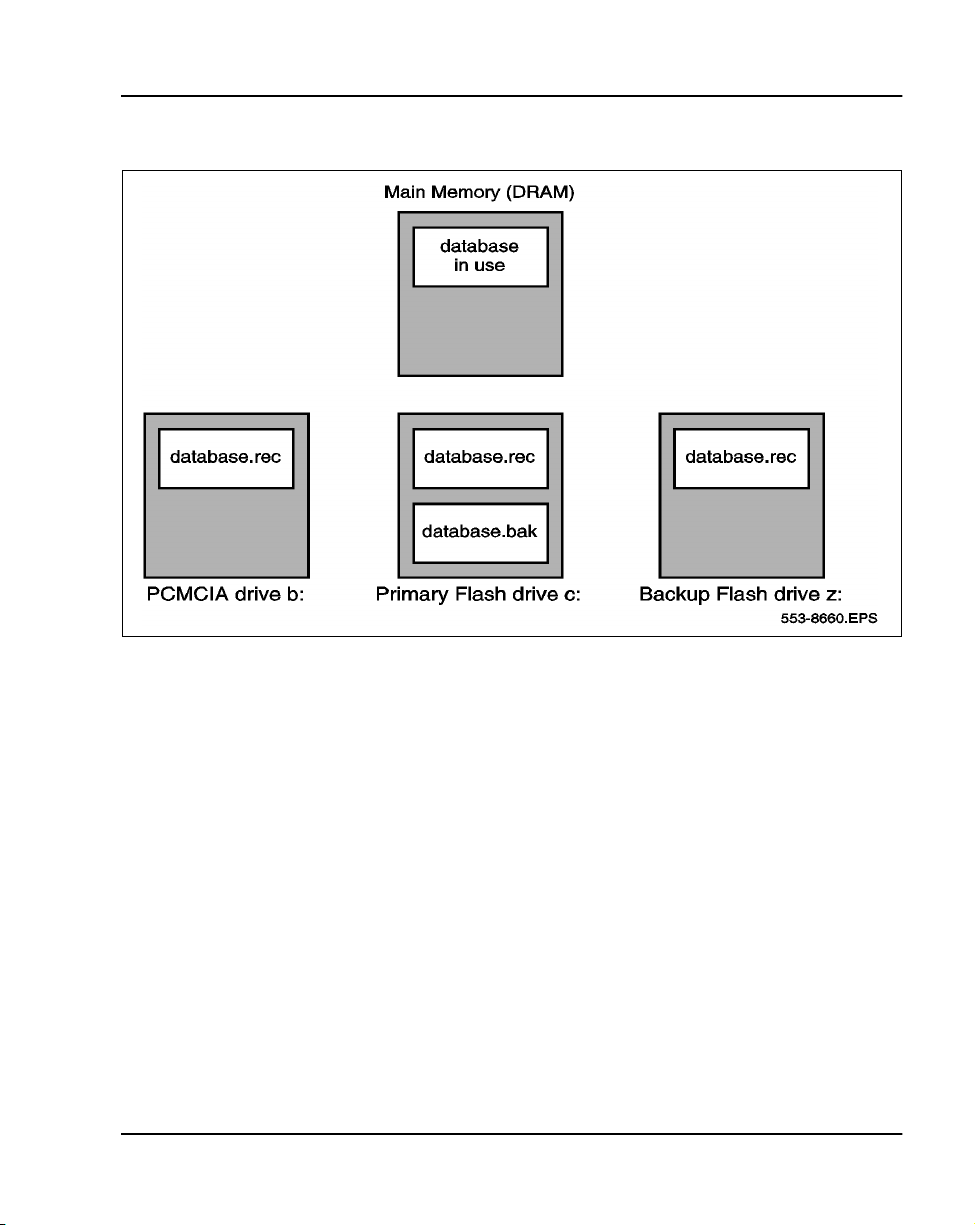
Option 11C and Option 11C Mini software is stored in various areas of the
NTDK20 SSC and NTDK97 MSC cards. In terms of customer data, there are
four possible areas where these records can be stored (Refer to Figure 1):
• DRAM — stores and accesses the active version of customer records,
system data and overlay data
• Primary Flash drive c: — contains two copies of customer records
(primary and backup records)
• Backup Flash drive z: — retains the true backup copy of the customer
database
• PCMCIA device a: or b: — if equipped, this 40 Mbyte device can store
a complete backup copy of the customer database
Option 11C and 11C Mini Technical Reference Guide
Page 14

Page 14 of 544 Memory, Storage and CPU capacity
Data storage
The Option 11C and 11C Mini data dump performed in LD 43, is the system’s
method of backing up configuration data to its file storage devices. By
invoking one of the several data dump commands in the overlay, the user is
ensured that at least one backup copy of configuration data exists in a location
other than DRAM (Refer to Table 1).
Tab le 1
LD 43 data dump commands
Command Description
BKO Customer records in the Primary Flash drive are copied to the PCMCIA
EDD Customer data in DRAM is written to the Primary and Backup flash drives
on the NTDK20 SSC and NTDK97 MSC.
EDD NBK Customer data in DRAM is written to the Primary and Backup flash drives
on the NTDK20 SSC and NTDK97 MSC. (Same as the EDD command).
SWP A swap or exchange of database records is completed between the Pri-
mary Flash drive’s main and secondary databases (Refer to Figure 1).
device.
The effects of the LD 43 commands described above are be better illustrated
by referring to Figure 1.
Note: Refer to the Option Maintenance (553-3001-511) for a complete
listing and description of LD 43 commands.
553-3011-100 Standard 14.00 January 2002
Page 15
Memory, Storage and CPU capacity Page 15 of 544
Figure 1
Data storage on the NTDK20 SSC and NTDK97 MSC
The Option 11C and Option 11C Mini offer one additional area of data
storage that is truly external to the switch. This storage device can be an IBMtype PC or Macintosh-type computer, running an Option11C software feature
called “Customer Configuration Backup and Restore” (CCBR). Through the
use of LD 143 and the CCBR feature, the user can transfer customer records
between the SSC or MSC’s Primary Flash drive to either an on-site or remotecomputer system (Refer to Table 2 for a listing of CCBR commands
supported in LD 143).
Option 11C and 11C Mini Technical Reference Guide
Page 16

Page 16 of 544 Memory, Storage and CPU capacity
Tab le 2
LD 143 CCBR commands
Command Description
XBK Customer database records in the Primary Flash drive are backed up to
XRT Customer database records are restored from an external computer
hard-drive to the Backup Flash drive and on the NTDK20 SSC and
XSL The Option 11C or Option 11C Mini is remotely “sysloaded” with cus-
tomer records stored in the Primary Flash drive.
XVR Customer files stored on an external computer are verified for validity and
an external computer hard-drive.
NTDK97 MSC.
integrity with records in the Backup Flash drive.
Note: Refer to Administration (553-3001-311) and Maintenance (553-
3001-511) for a complete listing and description of LD 143 commands.
Data loading
An Option 11C and 11C Mini “SYSLOAD” is a sequence of events whereby
the switch loads and verifies system and customer records into the NTDK20
SSC’s or NTDK97 MSC’s active memory area, or DRAM. The flow of data
depends on the status of the software - new installation, software release
upgrade, or a user-initiated sysload - or the commands initiated in either
LD 143, or the Install Setup Program.
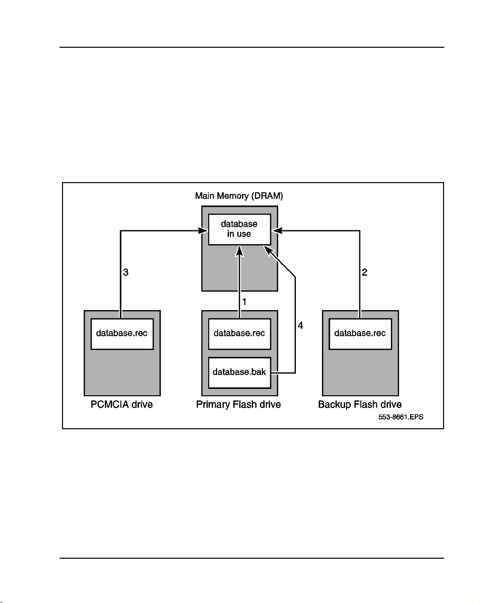
Despite the various ways to initiate a Sysload, the flow of data generally
follows the path described below (Refer to Figure 2 for a graphical
illustration):
1 The Option 11C and 11C Mini searches for customer records in the
Primary Flash drive. If the files are located and verified, data is loaded
into the NTDK20 SSC’s or NTDK97 MSC’s DRAM.
2 If the records are corrupt or cannot be found in the Primary Flash drive,
the system searches the Backup Flash drive. If the customer records are
located and verified, the Option 11C and 11C Mini loads the data into
DRAM.
553-3011-100 Standard 14.00 January 2002
Page 17
Memory, Storage and CPU capacity Page 17 of 544
3 If the customer records cannot be located in the Backup Flash drive, the
Option 11C and 11C Mini automatically searches the PCMCIA drive. If
customer records are located and verified, data is loaded into DRAM.
4 If the customer records cannot be located in the PCMCIA drive, the
Option 11C and 11C Mini searches the Primary Flash drive for the
secondary backup (.bak) file. If the customer records are located and
verified, data is loaded into DRAM.
Figure 2
Flow of data during an Option 11C or Option 11C Mini Sysload
Sysload and a new Option 11C or Option 11C Mini installation
Software for new Option 11C and 11C Mini systems is delivered on a preprogrammed Software Daughterboard for the Option 11C, or directly on the
MSC for the Option 11C Mini. Once this hardware is installed and the system
is powered up (SYSLOAD), the Install Setup and Loader program (LD 143)
is automatically invoked. This program is menu driven and assists in loading
the software into the system.
Option 11C and 11C Mini Technical Reference Guide
Page 18

Page 18 of 544 Memory, Storage and CPU capacity
Data restoring
In the unlikely event configuration data becomes corrupted, a backup copy of
the current database can be restored to the Option 11C and 11C Mini. There
are four possible areas of where a backup of configuration data can be
restored from — the secondary primary database, the backup flash drive, the
PCMCIA drive, or an external computer hard-drive. (Refer to Table 2 for a
description of the commands used to restore backup data to the Option 11C
and 11C Mini.)
Tab le 3
Commands used to restore data to the Option 11C and Option 11C Mini
Command Overlay Description
SWP
(see note)
RES 43 Restore files to the primary flash drive from the PCMCIA
RIB 43 Restores the missing files in primary flash drive from the
XRT 143 Customer database records are restored from an external
Note: The SWP command in LD 43 does not “restore” data to the primary flash drive: it swaps or replaces
the contents of the primary drive with the data stored in the primary drive’s secondary database.
43 Secondary primary files are “swapped” with the contents of
the primary flash drive (Refer to database.bak in Figure 2).
drive.
internal backup drive.
computer hard-drive to the Primary and Backup Flash drives
on the NTDK20 SSC or NTDK97 MSC.
Pre-programmed data
When an Option 11C or Option 11C Mini system is initially installed,
customer data must be entered into the overlay programs. Telephones, for
example, must be assigned features on their keys to allow them to function
properly.
However, the Main SSC or the Mini MSC can be pre-programmed with
customer data. If you load pre-programmed data into the system during
installation, some overlay entries will be automatically configured on the
telephones. For example, you can choose a telephone model that has
predetermined feature and key assignments and a preassigned class of
553-3011-100 Standard 14.00 January 2002
Page 19

Memory, Storage and CPU capacity Page 19 of 544
service. This can be a significant time-saver if you have to program numerous
types of telephone models.
Pre-programmed data is not mandatory for software installation. In fact, the
NTDK20 or the NTDK97, can be programmed with the minimum number of
files to allow the Option 11C and 11C Mini to operate.
During start-up, the Software Installation Program is automatically invoked.
The Option 11C or Option 11C Mini, loads system data from the NTDK20,
or the NTDK97 respectively, and prompts the user for a variety of
information, including the time and date, type of installation, feature set
required, and type of database. At this point, if the user selects any response
other than “Default database,” pre-programmed data will not be loaded on the
system.
Pre-programmed data cannot be removed from the Option 11C and 11C Mini
system once it is loaded into the system. However, pre-programmed data can
be bypassed during first-time system installations.
Note: The pre-programmed data on the Option 11C and 11C Mini
system can provide an effective starting point for programming
telephone and trunk information. Before bypassing the option of loading
pre-programmed data, take the time to determine whether the default
data can be used at this site.
Components of pre-programmed data
The following items are pre-programmed in the Default database on the Main
Option 11C NTTK13 Software Daughterboard:
• Model telephones
• Trunk route data and model trunks
• Numbering plan
• SDI ports
• Tone and digit switch
Model telephones
A model telephone can be thought of as a default set of features and class of
service assigned to a telephone.
Option 11C and 11C Mini Technical Reference Guide
Page 20

Page 20 of 544 Memory, Storage and CPU capacity
Telephone models simplify telephone installation. During telephone
activation, the telephone prompts you to accept a default model. If a model is
chosen, all keys are automatically assigned a feature and no further key
programming is required. (The extension number is also predefined using the
default numbering plan.)
If you do not want to accept the default model, you can create other models
by following the procedures in Chapter 19 of the Option 11C Planning and
Installation (553-3021-210), or Chapter 17 of the Option 11C Mini Planning
and Installation (553-3021-209).
Note: Off-Premise Station (OPS) telephones do not have their own
telephone models. You can, however, create OPS models by entering DD
in response to the CDEN prompt in LD 10.
Trunk route data and model trunks
Pre-programmed trunk routes and trunk models simplify trunk installation
procedures. A pre-programmed trunk route supports a certain trunk type, has
a default access code, and must be assigned a trunk model. A trunk model
supports a certain card type, trunk type, and signalling arrangement.
Trunk models are assigned to default trunk routes using the administration
telephone. You can create other models by following the procedures in
Chapter 20 of the Option 11C Planning and Installation (553-3021-210) or
Chapter 18 of the Option 11C Mini Planning and Installation (553-3021-
209).
Numbering plan
The pre-programmed numbering plan automatically assigns default extension
numbers to the following (this list may not be representative of all countries):
• Local extension numbers
• Attendant extension
• Night number
• ACD queues
• Meridian Mail extensions
• Call park extensions
553-3011-100 Standard 14.00 January 2002
Page 21

If the default numbering plan does not suit this system’s needs, you can
change it using the procedures Chapter 22 of the Option 11C Planning and
Installation (553-3021-210) or Appendix A of the Option 11C Mini Planning
and Installation (553-3021-209).
SDI ports
There are three pre-programmed SDI ports on Option 11C and 11C Mini
systems. The NTDK20 SSC or NTDK97 MSC provides TTY ports 0, 1, and
2. All three SDI interfaces can be used as either modem or maintenance ports
for TTY terminals.
Tone services
The SSC/MSC provides 30 channels of tone and cadence transmission to the
system.
The SSC/MSC also provides tone detection. Units 0-7 can be configured to
support DTR/XTD. Units 8-15 can also be configured to support DTR/XTD
Optionally, units 8-11 can be configured to support other tone detection
functions in lieu of DTR/XTD on units 8-15. These other tone functions
include one of MFC/MFE/MFK5/MFK6/MFR.
LD 56 contains default tables used for tone and cadence generation.
Memory, Storage and CPU capacity Page 21 of 544
Tab le 4
LD 56 tone and cadence data
TDS loop Channels 1-30
DTR or XTD Card 0, units 0-7
Benefits of pre-programmed data
The main benefit of pre-programmed data is that it simplifies installation and
activation procedures. Table 5 compares how a task would be performed
using pre-programmed data and how it would be performed without preprogrammed data.
Pre-configured TDS/DTR data
Option 11C and 11C Mini Technical Reference Guide
Page 22

Page 22 of 544 Memory, Storage and CPU capacity
Tab le 5
Benefits of pre-programmed data
Tas k
Activating
telephones
Activating
trunks
Establishing a
numbering
plan
Software Installation program and pre-programmed data
Task performed using preprogrammed data
Plug telephone into socket, lift
handset, choose model,
choose extension
Use the administration menu
to add a trunk:
• enter a route access code
• enter a TN
• enter a trunk model
No effort required. Default
extension numbers become
active when telephones are
activated. Default plan is
sequential.
Task performed without using
pre-programmed data
Enter LD 10 or 11, enter telephone type,
specify TN, assign class of service, assign
a feature to each key on telephone
LD 10 has approximately 120 prompts
LD 11 has approximately 160 prompts
Enter LD 16, enter trunk type, access code,
signalling arrangements
Enter LD 14, enter TN, route member
number, signalling arrangements, class of
service, and so on
LD 16 has approximately 200 prompts
LD 14 has approximately 50 prompts
A numbering plan must be developed to
map TNs to DNs.
The Software Installation program is automatically invoked when the new
Option 11C or Option 11C Mini is started up (SYSLOAD). After successfully
responding to various prompts in the program, you are given the option of
selecting a database to be loaded.
Detailed information about the Software Installation program can be found in
the Option 11C Planning and Installation (553-3021-210) or the Option 11C
Mini Planning and Installation (553-3021-209) used for first-time
installations; or the Option 11C and 11C Mini Upgrade Procedures (553-
3021-250) used for upgrades from an Option 11 or 11E to an Option 11C
system.
553-3011-100 Standard 14.00 January 2002
Page 23

Memory, Storage and CPU capacity Page 23 of 544
Removing pre-programmed data
Pre-programmed data cannot be removed from the Option 11C or Option 11C
Mini system once it is loaded into the system. However, pre-programmed
data can be bypassed during first-time system installations.
During start-up, the Software Installation Program is automatically invoked.
The Option 11C and 11C Mini then loads system data from the Software
Daughterboard, or MSC for the Option 11C Mini, and prompts the user for a
variety of information, including the time and date, type of installation,
feature set required, and type of database. At this point, if the user selects any
response other than “Default database,” pre-programmed data will not be
loaded on the system
Note: The pre-programmed data on the Option 11C and 11C Mini
system can provide an effective starting point for programming
telephone and trunk information. Before bypassing the option of loading
pre-programmed data, take the time to determine whether the default
data can be used at this site.
Customer Configuration Backup and Restore
The Customer Configuration Backup and Restore (CCBR) feature provides
the ability to store the configuration database of the Option 11C on an
external hard-drive of an IBM-type PC or Macintosh-type computer.
The CCBR feature can be invoked on-site with the use of a modem
eliminator, or remotely over a modem connection.
Operations performed
The CCBR feature performs two different functions of safeguarding
customer programmed data. The first involves storing the configuration
database in the unlikely event of an system failure - such as a continuous
SYSLOAD or INI - or data corruption. To correct this problem, the backup
copy of the configuration database can be restored to the Option 11C or
Option 11C Mini.
Option 11C and 11C Mini Technical Reference Guide
Page 24

Page 24 of 544 Memory, Storage and CPU capacity
The second function of the CCBR feature has to do with the role it plays in
upgrading software from an Option 11 or 11E to an Option 11C system. To
illustrate, if the CCBR feature is invoked in LD 43 of an Option 11 or 11E,
its configuration data can be backed up on a hard-drive of an external
computer. When the new Option 11C hardware is fully installed, and the
PCMCIA card is inserted in the System Core card, the backup copy of the
configuration data - stored on the computer - can be transferred back to the
upgraded Option 11C system as part of the software upgrade process.
Immediately upon download, the Option 11 or 11E database files will be
automatically converted to the Option 11C format.
Note: Whenever the CCBR feature is used, configuration data is always
backed up to the primary flash drive. Prior to invoking the CCBR
command, a data dump should be performed to ensure the primary
database is current.
File transfer time
Depending on the number of records in the configuration data base, it can take
over 30 minutes to backup or restore data at a rate of 1200 bps. CCBR access
time can be significantly decreased using a 19200 baud modem: 19200 baud
is the maximum data transfer rate supported by the Option 11C or Option 11C
Mini.
Equipment requirements
Communications software
Communications software compatible with XModem CRC protocol is
required to operate the CCBR feature. This requirement applies to on-site and
remote access.
On-site access
On-site access to the Option 11C or Option 11C Mini system can be made by
directly connecting a computer to SDI port 0, 1, or 2.
Note: You will need to connect a modem eliminator between the SDI
cable and the computer cable for on-site computer access.
553-3011-100 Standard 14.00 January 2002
Page 25

Remote access
Remote access to the Option 11C or Option 11C Mini is established by
connecting SDI port 0, 1, or 2 on the SSC/MSC to an analog line (Central
Office line) through an on-site modem. This will allow the computer to dial
directly into the Option 11C or Option 11C Mini from a remote location.
Detailed information about the CCBR feature can be found in the Option 11C
Customer Controlled Backup and Restore (CCBR) (553-3011-330).
Real time CPU capacity
Tab le 6
CPU capacity
Memory, Storage and CPU capacity Page 25 of 544
Release
16.90G 250 10075
18.30H 306 8225
18.40H 300 8400
20.06 338 7450
20.19 374 6750
21.0x 373 6075
22.0x 50 58000
23 50 55775
24 47 50175
25 49 46324
Average Msecs of CPU for PBX Call
(Equivalent Basic Call)
Equivalent Basic IPE Calls per
Hour
Option 11C and 11C Mini Technical Reference Guide
Page 26

Page 26 of 544 Memory, Storage and CPU capacity
Tab le 7
Option 11C Real Time Measurements PRI Calls (msecs) (with IP Expansion)
Call Type 2527d(2530) No Expansion cabinet
pbx - tie 57 89
tie - pbx 51 86
aries - tie 56 127
tie - aries 59 99
tie - tie
Average 58 100
Figure 3
Option 11C Real Time Measurements i2004 Calls (msecs)
ITG card on Expansion cabinet
Call Type
i2004-aries 236 231
aries-i2004 197 190
i2004-i2004 323 321
PRI card on Expansion cabinet
2527d
2527d (2530) With IP Expansion
ITG card on Main cabinet
PRI card on Expansion cabinet
cabinet
2527d
i2004-tie 319 321
Option 11C memory requirements are calculated using the following tables:
• Table 9 on page 28 - Resident Program Store
• Table 10 on page 29 - IP Memory Impacts
• Table 11 on page 30 - Unprotected data store requirements
• Table 12 on page 48 - Protected data store requirements
553-3011-100 Standard 14.00 January 2002
Page 27

Record the memory requirements on “Worksheet D: Unprotected memory
calculations” on page 141 and “Worksheet E: Protected memory
calculations” on page 142.
Network Delay
There is some impact on real-time performance (estimated to be 20%) when
digital trunks are installed in IP Expansion cabinets. However, there is still
sufficient real-time to support five fully configured Option 11C cabinets in a
typical business configuration.
Table 8
Basic LAN Requirements for Excellent Voice Quality
LAN requirement Value for Excellent Voice Quality
Packet loss rate <0.5%
PDV jitter buffer (maximum) RTD<5 ms
Round trip Delay <5 ms
PDV jitter buffer (minimum) RTD<12 ms
100BaseT/F Layer 2/Layer 3 switch Full Duplex connection
Memory, Storage and CPU capacity Page 27 of 544
Option 11C and 11C Mini Technical Reference Guide
Page 28

Page 28 of 544 Memory, Storage and CPU capacity
Software Program store
Resident Program store
The Resident Program store requirements are listed in Table 9
Tab le 9
Resident Program Store
Program 1024 words = 1K Storage in words
Basic (BASE)
Read/Write Firmware
Overlay
Options (OPTF) 0
Multi Customer (CUST)
ROM Firmware
To t a l 54 000
0
0
46 000
0
8 000
553-3011-100 Standard 14.00 January 2002
Page 29

Memory, Storage and CPU capacity Page 29 of 544
For IP connectivity, extra memory usage is required. Table 10 summarizes
the additional memory requirements of the Survivable IP configuration.
Tab le 10
IP Memory impacts
Functional area Flash DRAM C-drive PCMCIA
CDR storage 4 Mb (17500)
Survivable db x x x
star t-up 3K 2K 3K
100baseT/F 218981 B
multi-clock 28 words
cardlan 30K
SSD 40K
IP config 0.8K 0.8K 0.8K
voice 1K
bootP 20K 0.8K 0.8K
remote TTY 35K
TOTAL
Option 11C and 11C Mini Technical Reference Guide
Page 30

Page 30 of 544 Memory, Storage and CPU capacity
Data store requirements
Unprotected data requirements
Table 11 lists the unprotected data store requirements per item in words.
Tab le 11
Unprotected data store requirements (Part 1 of 4)
Data Store by Feature
Fixed Address Globals 22389 -
500-type telephones 8.5 -
2500-type telephones 8.5 -
SL-1 sets (no digit display) 20.25 -
SL-1 sets (digit display) 22.25 -
Add-on K/L Strips 10 -
Data Service/VMS Access TNs - See Note 10 on page
Analog Trunks - See Note 17 on page
BRI Trunks 83 -
DTI 82 -
JDM/DTI2 57 -
ISDN PRI/PRI2/ISL - See Note 18 on page
Fixed Number of 1k
Words per Item
Calculated number
of Words Per Item
40
44
46
Attendant 131 -
Customers 234 -
Console Presentation Group (CPG) Data
Block
Trunk Routes - See Note 1 on page
553-3011-100 Standard 14.00 January 2002
29, 35 #Customer, #CPG
34
Page 31

Memory, Storage and CPU capacity Page 31 of 544
Tab le 11
Unprotected data store requirements (Part 2 of 4)
Data Store by Feature
Fixed Number of 1k
Words per Item
Calculated number
of Words Per Item
Network-Location Code 69 -
Tone and Digit Switch 59 -
Conference 166 -
Digitone Receivers 12 -
MFR - MF Receiver - See Note 20 on page
47
Tone Detect 12 -
Low Priority Input Buffers (LPIB)
(from note 4)
High Priority Input Buffers (HPIB)
(from note 4)
4 See Note 11 on page
41
4 See Note 11 on page
41
PBXOB 4 x PBXOB See Note 11 on page
41
BCSOB 4 x PCSOB See Note 11 on page
41
AML (CSL) - See Note 21 on page
47
MSDL 1273 -
Automatic Call Distribution (ACD) - See Note 3 on page
35
ACD Enhancement - See Note 8 on page
39
ESN Communication Management Cen-
350 -
ter (CMAC)
NARS/BARS/CDP - See Note 4 on page
36
Option 11C and 11C Mini Technical Reference Guide
Page 32

Page 32 of 544 Memory, Storage and CPU capacity
Tab le 11
Unprotected data store requirements (Part 3 of 4)
Data Store by Feature
Fixed Number of 1k
Words per Item
Calculated number
of Words Per Item
BGD Terminal Time 13 -
BGD/AWU Traffic Block 350 -
Call Register 161 See Note 5 on page
37
Call Park - See Note 6 on page
39
Integrated Message System Link (IMS) 16 See Note 7 on page
39
Auxiliary Processor Link (APL) 179 -
Automatic Trunk Maintenance (ATM)
- No impact
Schedule Block
ATM Data Block - No impact
Digital Telephones - See Note 9 on page
40
Multi-Tenant 32 -
Command Status Link (CSL) (143 + 483) x #Links -
Background Terminal 89 -
Display Messages 12 -
ISDN Basic Rate Interface (BRI) See Note 16 on page
42
ISDN Primary Rate Access
81 -
(PRA)
553-3011-100 Standard 14.00 January 2002
Page 33

Memory, Storage and CPU capacity Page 33 of 544
Tab le 11
Unprotected data store requirements (Part 4 of 4)
Data Store by Feature
Fixed Number of 1k
Words per Item
Calculated number
of Words Per Item
Overlay Data Space 260 -
ISDN Signalling Link (ISL) 81 -
Enhanced Busy Lamp Field (EBLF) - See Note 13 on page
42
Enhanced Night Service 1 -
Periodic Pulse Metering (PPM) - See Note 14 on page
42
Flexible Feature Codes (FFC) 3 -
Group Hunt 17 -
Model Telephones - See Note 15 on page
42
Model Trunks - See Note 15 on page
42
IP Expansion See Note 22 on
page 47
Option 11C and 11C Mini Technical Reference Guide
Page 34

Page 34 of 544 Memory, Storage and CPU capacity
Notes to Table 11
The following notes are referred to in Table 11.
Note 1
The size of the trunk block is calculated from:
CT + w + x + y + z (words) where:
CT = 10
w = line block (see table below)
Trunk Types Other MS
RAN 5 5
RLA 15 14
ADM 18 18
IDA 43 43
Others 29 29 (Includes ISA)
x = 0 if the trunk belongs to a route which does not have CDR or has CDR
with dialed digits
x = 9 if the trunk belongs to a route which has CDR with outpulse digits
y = 0 if the trunk belongs to a route which does not have the Timed Forced
Disconnect option
y = 5 if the trunk belongs to a route which has the Timed Forced Disconnect
option
z = 0 if the trunk does not have CNA defined
z = 4 if the trunk has CNA defined
553-3011-100 Standard 14.00 January 2002
Page 35

Memory, Storage and CPU capacity Page 35 of 544
Note 2
The size of a TTY block (in words) is calculated from:
t + x,
where t = 2075 and
x is defined in the following table:
Input Buff Data Output Q
CDR Link 128
HS Link 128 + 15
APL Link 128 + 179 + 4
PMS Link 128 + 2
Other 128
Note 3
For ACD features, the following additional storage per system is required:
K0 x [(K1 x CROUT) + (K2 x CPID) + (K3 x CDN) + CTM + (K4 + CRT)
+ (K5 x CCUST)] + (K6 x DN) + (K7 x PID) + (K8 x DN)
Where the multiplication constants (Ki) are:
K0 = 0 if ACD-C package is not equipped
K0 = 1 If ACD-C package is equipped
K1 = 46
K2 = 14 If long report is selected
K2 = 42 If short report is selected
K3 = 80
K4 = 30
K5 = 240
K6 = 149
Option 11C and 11C Mini Technical Reference Guide
Page 36

Page 36 of 544 Memory, Storage and CPU capacity
K7 = 29
+ 2 for DN Expansion
+ 1 for ACD ACNT CODE
+ 1 for 500/2500 ACD set feature
K8 = 0 if priority agent package (PAGT) is not equipped
K8 = 32 for Option 11C with PAGT
And the variables represent the following:
CCUST = total number of customers with ACD-C package
CDN = total number of ACD DNs for ACD-C customers
CPID = total number of AGENT POSITIONs for ACD-C customers
CROUT = total number of ACD routes in ACD-C customers
CTM = total number of TRUNK members in CROUT
DN = total number of ACD DNs (for system)
PID = total number of AGENT POSITIONs (for the system)
CRT = total number of ACD CRTs
Note 4
If the NTRF package is equipped, the unprotected data store requirements (on
a per customer basis) for NARS/BARS/CDP are as follows:
COS = TRAFSIZE + RLSIZE + NCOSIZE + QROUTSIZE
where:
If OHQ or MCBQ is equipped
TRAFSIZE 216 200
RLSIZE = 2 x (45 x RL) 2 x (40 x RL)
NCOSIZE = 2 x (10 x NCOS) 2 x (6 x NCOS)
QROUTSIZE = 2 x (12 x QROUT) 0
553-3011-100 Standard 14.00 January 2002
If OHQ or MCBQ not
equipped
Page 37

Note 5
Memory, Storage and CPU capacity Page 37 of 544
QROUT = number of routes with either CBQ or OHQ
RL = number of route lists
NCOS = number of NCOS defined
The total number of Call Registers may not exceed 2048. The recommended
number of Call Registers is:
(T + 815)/33.8 + M + X + Y
where:
T = (A/2 x C x 1.42) - (M x L)
A = the total voice loop traffic in CCS
C = the call register factor
= 1
+ 0.037 if CDR Charge Account
+ 0.150 if NARS/BARS/CDP
+ 0.150 of FCBQ and OHQ
+ 0.033 if ACD RAN
+ 0.019 if Telset Messaging
+ 0.140 if Integrated Messaging System
+ 0.083 if Ring Again
+ 0.033 if Music Trunk
+ 0.067 if Call Park
+ 0.003 if New Flexible Code Restriction
+ 0.039 if ESN signalling
+ 0.000 if Stored Number Re-dial (negligible impact)
L = average CCS per ACD trunk
M = the number of ACD incoming trunks
X = 0 if no Network ACD (NACD)
= the number of ACD calls which overflow out of Source ACD DNs
on this node
=(# Source ACD DNs) x (average overflow from Source ACD DNs)
Option 11C and 11C Mini Technical Reference Guide
Page 38

Page 38 of 544 Memory, Storage and CPU capacity
Y = 0 if no Network ACD (NACD)
= the number of ACD calls which overflow into Target ACD DNs
in this node
= (# Target ACD DNs) x (average overflow into Target ACD DNs)
The averages for NACD overflow must be estimated, and should be
engineered for peak periods.
Assumptions for Call Register Factors:
• The peak day traffic = 1.42 x ABSBH for business offices.
• All outgoing calls require authorization (worse case assumption).
• An additional call register is required for 20 seconds to hold the
authorization code.
• Fifty percent of outgoing calls use the charge account feature (worse case
assumption).
• An additional call register is required for 20 seconds to hold the charge
account.
• The additional holding time of the call register for CDR purposes is 5
seconds.
• The average number of ports used in the multiple CDR ports feature is 2.
• A call register is required for each incoming ACD trunk.
• The intra-office ratio R = 0 (worse case assumption).
• The number of originating calls equals the number of terminating calls.
• The blocking peak of the day traffic is P0.01.
• The average NARS/BARS call takes 20 seconds to dial and 20 seconds
to complete outpulsing and delay for answer.
• The average holding time of a RAN is 15 seconds.
• The average Telset Message takes 6 seconds to dial and 20 seconds to
complete outpulsing and delay for answer.
• The average IMS call takes 8 seconds to dial, 15 seconds ringing and 40
seconds with message attendant. During the busy hour, 60 percent of
terminating calls are unanswered, of which 50 percent require IMS.
• A call register is required for active Ring Again call.
553-3011-100 Standard 14.00 January 2002
Page 39

Memory, Storage and CPU capacity Page 39 of 544
• Music Trunk holding time is 30 seconds.
• Average Call Park holding time is 1 minute.
• Average holding time for New Flexible Code Restriction is 4 seconds.
• ESN Signaling Feature holding time is 15 seconds and 25 percent of calls
need the signaling feature.
Note 6
Size per item for Call Park:
k + ceiling (s/16), for UCALL_PARK_BLOCK
where,
s = number of System Park DN's per customer.
k = 6, size(UCALL_PARK_BLOCK) (6.0)
Note 7
IMS unprotected memory requirements are:
LINK_OQ_TBL 16 words
APL_LINK_DATA 179 words x N *
QUEUE_DATA_BLOC 4 words x N*
N number of APL links defined in CFN Block
Total IMS Unprotected (16 + (183 x N)) words
* (183 x N) words are already accounted for in “Note 2” on page 35.
Note 8
ACD Enhancement - an ACD-C customer (See Note 3 on page 35).
Option 11C and 11C Mini Technical Reference Guide
Page 40

Page 40 of 544 Memory, Storage and CPU capacity
Note 9
Unprotected data store (size in words) for digital telephone ports:
Voice or Data Ports without Digit
Display
M2006 18 20
M2008 18 20
M2009 24.25 26.25
M2016 26 28
M2018 35.25 37.25
M2112 26.25 28.25
M2216 26 + 24 x #AOM 28 + 24 x #AOM
M2317 41.25 43.25
M2616 26 + 24 x #AOM 28 + 24 x #AOM
M3000 51.25 53.25
VOD Ports with Digit Displ ay
#AOM = Number of Add-on Modules
Note 10
The additional unprotected data store for a virtual terminal (DS access TN, or
VMS access TN) is dependent on the card to which the terminal is assigned.
The increment in words are as follows:
Preallocated card Otherwise
DS/VMS Access TN: 15 16.25
Where a preallocated card is one of the following: 0/1-0/7, 1/1-1/8, 2/1-2/8 or
3/8 on a Digital Line Interface (DLI) loop. (See Note 12 on page 41.)
553-3011-100 Standard 14.00 January 2002
Page 41

Memory, Storage and CPU capacity Page 41 of 544
Note 11
The size of Input/Output buffers is specified in “messages”. Each message
uses 4 words of unprotected data store. The recommended size for I/O buffers
is:
LPIB (Low Priority Input Buffers) = 96 messages
HPIB (High Priority Input Buffers) = 32 messages - single group 32 x #
groups - multi-group
PBXOB (Non-SL-1 Output Buffer) = 160 messages
BCSOB (SL-1 Output Buffer) = 160 messages
Note 12
The DCHI supports both 1.5 Mb PRI and 2.0 Mb PRI.
Each DCHI consists of the following unprotected data blocks:
DCH_U_BLOCK 60 words
Output Request Buffers 5 x number of OTBFs
(LD 17)
Output Buffer 261 words
Input Buffer 261 words
Unprotected call reference table 2 + M
Unprotected message link table 1 + M
M is computed for each DCHI, depending on Mode, as follows:
PRA Mode M = NChan x [Highest Loop Interface ID(defined in LD 17 by PRI
ISL Mode M = maximum number of ISL trunks defined
Shared Mode M = the sum of the values for PRA and ISL mode
111 nn)(zero if not defined)+ 1 (for primary channel_+1 (if
backup channel is on)
2Mb PRI only: unprotected data block = 91 words.
Option 11C and 11C Mini Technical Reference Guide
Page 42

Page 42 of 544 Memory, Storage and CPU capacity
Note 13
The following applies to each customer:
• Two words are required in the attendant unprotected data block (per
attendant console). This requirement is already accounted for in the size
of the attendant data block.
• If EBLF (Enhanced Busy Lamp Fields) is on (LD 15), there is a bit
required to indicate the busy or idle status of each DN. This amounts to
7 (16 bit) words per hundred groups defined.
Note 14
Total Unprotected data store per system is increased by the following:
(2 x CR) + (4 x BGD) + TRUNK + PPM_CARD + 4
where:
CR = number of Call Registers defined
BGD = number of background terminals
TRUNK = number of trunks
PPM_CARD = number of CO or E&M trunk card
Note 15
Model telephones and trunks require card block components only.
Model trunks — average 5 words
Model telephones — average 2 words
Note 16
The following tables show unprotected memory requirements for ISDN Basic
Rate Interface.
553-3011-100 Standard 14.00 January 2002
Page 43

Memory, Storage and CPU capacity Page 43 of 544
Per System :
Function Memory Requirements
MISP input buffer 170 words per system
MISP expedited input buffer 128 words per system
Per MISP:
Function Memory Requirements
MISP loop block 270 words
MISP output buffer (transmit receive) 512 words
MISP expedited output buffer 32 words
MISP output request buffer 7 words
MISP block data block 303 words
Socket ID table 48 words
Meridian 1 expedited receive buffer 128 words
Meridian 1 receive buffer 266 words
Meridian 1 expedited transmit buffer 528 words
MISP traffic accumulating block 48 words
MISP traffic holding block 48 words
Option 11C and 11C Mini Technical Reference Guide
Page 44

Page 44 of 544 Memory, Storage and CPU capacity
Per DSL:
Function Memory Requirements
2 TN line blocks 2 x 9 words
SSD block 10 words
Incoming call reference table 33 words
Outgoing call reference table 33 words
Incoming call ref. usage map 4 words
Outgoing call ref. usage map 4 words
Incoming message call reg. table 33 words
Outgoing message call reg. table 33 words
BRI DSL data block 3 words
Per BRSC:
Function Memory Requirements
BRSC data block 48 words
MISP traffic accumulating block 48 words
MISP traffic holding block 48 words
Per Line Card:
Function Memory Requirements
LIne card 5 words
Note 17
The size of the trunk block is calculated from:
CT + x + y + z (words)
553-3011-100 Standard 14.00 January 2002
Page 45

Memory, Storage and CPU capacity Page 45 of 544
where, 9 average card block + 6 trunk timing block
CT = 15 words
x = (see the following table) --> line block
y = 9 CDR extension
z = 0 If the trunk belongs to a route which does not have the Timed
Forced Disconnect option, or
z = 6 If the trunk belongs to a route which has the Timed Forced
Disconnect option.
Trunk Type Memory Requirements
RLA 20 words
ADM 72 words
IDA (DPN) 65 words
IDA (DASS) 53 words
OTHERS 61 words
Option 11C and 11C Mini Technical Reference Guide
Page 46

Page 46 of 544 Memory, Storage and CPU capacity
Note 18
The DCH application supports both 1.5 Mbit PRI and 2.0 Mbit PRI2.
527 per system
197 + 2 x M
Where:
M is computed as follows for each DCHI, depending on Mode:
PRA Mode:
If PRI is defined:
M = NChan * (nn + 1)
If PRI is NOT defined:
M = NChan * [1 (for primary channel)
+ 1 (if backup channel is on)]
Where:
nn = Highest Loop Interface Id (defined in Ovl17 by PRI lll nn), and
NChan = 24 for PRI and 31 for PRI2.
ISL Mode:
M = maximum number of ISL trunks defined.
Shared Mode:
M is the sum of the values for PRA and ISL Mode.
PRI2 only:
Unprotected data block = 68 words
553-3011-100 Standard 14.00 January 2002
Page 47

Note 19
Note 20
Note 21
Note 22
Memory, Storage and CPU capacity Page 47 of 544
The size of the memory requirements needed for junctor groups are:
(N x (N - 1)/ 2) x 73
Where:
N = Number of junctor groups
Memory requirement are calculated for MFR from:
7 x (# MFR Cards) + 3 x (# MFR Units)
Memory requirements are calculated for AML from:
143 + 483 x (# Links(AML))
To support IP Expansion in IP expansion cabinets, an additional 2.0 Mb of
memory is required on the Main and each survivable IP expansion cabinet.
An additional 0.5 Mb (only) is required on any non-survivable IP expansion
cabinets.
Memory requirements are calculated as follows:
Total memory = 2K + (5.25K + Number of Maintenance
Connections) + (16K + Number of I/O Connections)
Option 11C and 11C Mini Technical Reference Guide
Page 48

Page 48 of 544 Memory, Storage and CPU capacity
Protected data requirements
Tab le 12
Protected data store requirements (Part 1 of 5)
Data Store by Feature
Fixed Address globals 9220 -
500 sets - See Note 1 on page 53
2500 sets - See Note 1 on page 53
M2000 Series - -
Delta-II M2000 Series - See Note 64 on page 85
DS/VMS Access TN's - See Note 65 on page 85
AOM 10/rs -
DS/VMS/ACC/TNs - See Note 23 on page 67
Template Head Table - See Note 50 on page 79
Te m p la t e s - See Note 50 on page 79
Trunks 20 See Note 19 on page 66
Attendant - See Note 2 on page 55
Auxiliary Customer 187 -
Customers - See Note 31 on page 70
Fixed Number of 1k
Words per Item
Calculated number of
Words Per Item
CPG Level Services 46 -
Trunk Routes - See Note 28 on page 69
Code Restriction 51
New Flexible Code Restriction - See Note 16 on page 65
Peripheral Signaling 30 -
Digitone Receivers 9 -
553-3011-100 Standard 14.00 January 2002
Page 49

Memory, Storage and CPU capacity Page 49 of 544
Tab le 12
Protected data store requirements (Part 2 of 5)
Data Store by Feature
Fixed Number of 1k
Words per Item
Calculated number of
Words Per Item
Tone Detectors - See Note 53 on page 80
DLI/DTI - See Note 55 on page 81
DN Translators - See Note 3 on page 56
Serial Data Interface (N x 8) -
Application Module Link (N x 18) -
Dial Intercom Group(DIG) Translator - See Note 4 on page 58
Speed Call Master Head - See Note 31 on page 70
Speed Call Head Table - See Note 14 on page 64
Speed Call List - See Note 5 on page 58
Configuration 84 -
Configuration - Aux. 112 -
Basic Automatic Route Selection
- See Note 6 on page 59
(BARS)
Flexible Tones and Cadences (FTC) - See Note 35 on page 72
Enhanced FTC (EFTC) - See Note 35 on page 72
Network Automatic Route Selection
- See Note 7 on page 60
(NARS)
Coordinated Dialing Plan (CDP) - See Note 8 on page 61
and Note 51
Automatic Call Distribution (ACD) - See Note 9 on page 62
Network ACD (NACD) - See Note 36 on page 72
Group DND (Do Not Disturb) - See Note 10 on page 63
Direct Inward System Access (DISA) - See Note 11 on page 63
Option 11C and 11C Mini Technical Reference Guide
Page 50

Page 50 of 544 Memory, Storage and CPU capacity
Tab le 12
Protected data store requirements (Part 3 of 5)
Data Store by Feature
Fixed Number of 1k
Words per Item
Calculated number of
Words Per Item
Authority Code - See Note 12 on page 63
CAS - Main 0
CAS - Remote 15 -
History File - See Note 13 on page 64
Logical I/O - See Note 58 on page 82
Physical I/O - See Note 59 on page 82
Call Park - See Note 51 on page 79
Integrated Message System Link (IMS) 370 See Note 15 on page 65
New Flexible Code Restriction (NFCR) - See Note 16 on page 65
Soft Memory 35 -
Code Screening - See Note 18 on page 66
M2006 - See note on page 72
M2008 - See Note on page 73
M2216/M2616 - See Note on page 74
Add-on modules 20/rs -
Multi-tenant See Note 20 on page 66
ATM Schedule Block - See Note 22 on page 67
Digital Line Interface (DLI) - See Note 17 on page 66
Enhanced Serial Data Interface (ESDI) 16 + N x 9
-
(N = # of ports)
Command Status Link (CSL) 4 -
Value Added Server (VAS) 16 + N (N = # of servers) -
553-3011-100 Standard 14.00 January 2002
Page 51

Memory, Storage and CPU capacity Page 51 of 544
Tab le 12
Protected data store requirements (Part 4 of 5)
Data Store by Feature
Fixed Number of 1k
Words per Item
Calculated number of
Words Per Item
VAS DSDNs - See Note 24 on page 67
IMP - See Note 60 on page 82
Call Party Name Display (CPND) - See Note 26 on page 68
Line Load Control (LLC) 5 -
ISDN BRI - See Note 47 on page 74
ISDN PRA - See Note 27 on page 69
ISDN PRA - See Note 28 on page 69
ISDN PRI2 - See Note 56 on page 81
ISDN PRI2 - See Note 56 on page 81
DTI1 - See Note 57 on page 81
Automatic Wakeup (AWU) Count 288 -
ISDN Signaling Link (ISL) - See Note 30 on page 70
Enhanced Busy Lamp Field (EBLF) - See Note 33 on page 71
BGD Automatic Timed Job - See Note 52 on page 80
Pretranslation - See Note 33 on page 71
LAPW - See Note 61 on page 83
Name Display for DMS - See Note 62 on page 84
Option 11C and 11C Mini Technical Reference Guide
Page 52

Page 52 of 544 Memory, Storage and CPU capacity
Tab le 12
Protected data store requirements (Part 5 of 5)
Data Store by Feature
Fixed Number of 1k
Words per Item
Calculated number of
Words Per Item
FGD ANI Database - See Note 63 on page 84
Direct Inward Dialing/Direct Outward
1 Dialing
(DID/DOD)
Trunk Barring - See Note 37 on page 72
Periodic Pulse Metering (PPM) - See Note 39 on page 72
Flexible Feature Code (FFC) - See Note 40 on page 73
Network Attendant Console Service - See Note 41 on page 73
Group Hunt 10 -
ABCD - See Note 42 on page 73
Model Telephones - See Note 42 on page 73
Model Trunks - See Note 43 on page 73
553-3011-100 Standard 14.00 January 2002
Page 53

Memory, Storage and CPU capacity Page 53 of 544
Notes for Table 12
The following notes are referred to in Table 12.
Note 1
The size of the protected line block for Analog (500/2500 type) telephones is
determined from the following:
Basic Line Block = 10 words
Basic Line Block (ODAS) = 13 words
Card Block component = 2 words (1/4 pcard block)
The key layout portion of the template requires (4 + nf)/rs where “nf” is the
number of features defined for the set, and “rs” is the number of sets sharing
the same template.
In addition to the basic line block, each feature requires extra data space as
follows:
Tab le 13
Feature data space requirements (Part 1 of 2)
DN words words
Dial Intercom Group 2 words word
Speed Call User 1 word word
System Speed Call User 1 word word
Speed Call Controller 1 word word
Call Forward Number 1-6 words (4-24 digits) words (4 - 24 digits)
Call Park 2 words words
CFCT 2 words words
CFNA/Hunting Number 4 words words
Stored Number Redial 1-8 words (4 - 32 digits) words (4 - 32 digits)
Manual Line 2 words words
Message Center DN 2 words words
Option 11C and 11C Mini Technical Reference Guide
Page 54

Page 54 of 544 Memory, Storage and CPU capacity
Tab le 13
Feature data space requirements (Part 2 of 2)
DN words words
Hot Line DN 2-10 (words(1 - 31 digits) words (1 - 31 digits)
Tenant Number 1 word word
Internal Call Forward 19 words words
Last Number Redial 1-8 words words
SCI/CCOS/RMS 2 words word
Authcode 6-24 words words
Automatic Wake Up 2 words word
Message Registration 1 word word
Call Party Name Display 1 word (if name is defined for
this DN)
word (if name is defined
for this DN)
Offhook Interdigit Index 1 word word
Pre-translation Enhancement 1/2 word (for 255 calling
groups)
Word (for 255 calling
groups)
CFCT 2 words words
EHOT feature 2-10 words words
FAXS 17 words words
FFC SCP PASS 2 words words
Associate Set (AST) 2 words words
EFD/EHT/ DN 4 words words
553-3011-100 Standard 14.00 January 2002
Page 55

Note 2
Memory, Storage and CPU capacity Page 55 of 544
The size of the protected line block for attendant telephones is determined
from the following:
Primary Line Block = 205 words
Secondary Line Block = 6 words
Card Block Component = 4 words
In addition to the basic line block, each feature requires extra data space as
follows:
Autodial Key = 8 words
Paging Key = 2 words
Store Number Redial Key = 8 words
Option 11C and 11C Mini Technical Reference Guide
Page 56

Page 56 of 544 Memory, Storage and CPU capacity
Note 3
The memory requirements for the Directory Number (DN) Translator are
shown in the table below. The memory requirements are formulated as a sum,
for which each row in the table describes an additive term; a term consisting
of factor * item. Factors and items are represented by constants, variable
descriptions and combinations of these. Units are words of protected data
store.
Tab le 14
Directory Number (DN) data space requirements (Part 1 of 2)
Factor Factor Description Item Item Description
2 S # of different DN's appearing on SL-
1 # of appearances of DN's within S
12 size(DNXBLOCK) Sum
N's
number of ACD DN's 2
number of ACD DN's 2 x AI size(ACD_ID_DNBLOCK) x
# DISA DN's 2 size(DISA_DNBLOC)
1 number of System Park DN's
1 number of listed DN's
# defined DN's 2
1 66 1 + size(ATTN_DNBLOC)
1/500/2500 sets
1+N1+N2+N3+N4+N5+N6: see
below
# ACD position ids in each ACD DN
553-3011-100 Standard 14.00 January 2002
Page 57

Memory, Storage and CPU capacity Page 57 of 544
Tab le 14
Directory Number (DN) data space requirements (Part 2 of 2)
Factor Factor Description Item Item Description
1 If special service prefix
defined.
If special service prefix
defined.
1 If RSANI access code defined. 11 size(RSANI_BLK).
1 If CAS hold DN defined. 2 1+size(CAS_HOLD_DNBLOCK)
1 If CAS hold DN defined. 2 1+size(CAS_RLT_DNBLOCK).
# CDP steering codes defined 3 size(CDP_DATA_BLOCK)
# Testline DN's 2 size(TSTLINE_DNBLK)
# ACD DN's defined 3 size(ACD_DNBLOCK)
# DIG groups defined 2 size(DIG_DATA_BLK)
# SL1 DN's 2 size(BCS_DNENTRY)
1
3
Where
Nn = number of different sequence of the first n digits in the numbering plan
(if DN is more than n digits).
Option 11C and 11C Mini Technical Reference Guide
Page 58

Page 58 of 544 Memory, Storage and CPU capacity
Note 4
The equation for calculating the protected memory requirement for dial
intercom data is shown in the table below. The memory requirements are
formulated as a sum, for which each row in the table describes an additive
term consisting of factor * item. Factors and items are represented by
constants, variable descriptions and combinations of these. Units are words
of protected data store.
Refer to page 71 for computation of DIG CPND Name Pointer Table Size.
Tab le 15
Protected memory for dial intercom data
Factor Factor Description Item Item Description
1 1 + configured max # of DIGs (OV 15)
actual # of DIGs configured
actual # of DIGs configured
Note 5
The size of a speed call list is:
((NB - 1) x 256) + (NBR x WE)
where:
NB and WE are calculated as described in Note 14 under the Speed Call List
Head Table, and NBR is the remainder of the calculation to determine NB,
which is:
NB = EL/EB
2
2 x avg size(DIG_DATA_BLK) * avg # mem-
bers in each DIG
553-3011-100 Standard 14.00 January 2002
Page 59

Note 6
Memory, Storage and CPU capacity Page 59 of 544
The protected data store requirements for BARS (on a per customer basis)
are:
BASIC_ESN + SUM + RL x (8 + 3 x RLE) + DME x (4 + I/4)
+ FCAS + SDRR x (3 + 2 x SDE) + ITGE
where:
BASIC_ESN = Size(ESN_DATA_BLOCK) +
Size(NCTL_DATA_BLOCK)
SUM = (Size(ESN_TRAN_BLOCK) x [(10 x (#digits (0-9)) x R) x N] -1
(10 x R) -1
Size(ESN_TRAN_BLOCK) = 11
Size(ESN_DATA_BLOCK) = 131
Size(NCTL_DATA_BLOCK) = 506
n = maximum level of tree (n>0)
R = the rate of digits equipped in each level of the tree (translator)
RL = number of route lists
RLE = average number of route lists entries per route list
DME = number of distinct digit manipulation entries (including the default
0th entry)
I = average number of digits that must be inserted as part of digit
manipulation
FCAS = (N + 1) + N(M + 1) + MN[4 + (100P + 15)/16]
where:
N = number of defined FCAS tables
M = average number of NPA codes per table
P = average number of the first digits in NXX codes
SCC = number of entries in the SCC table
SDRR = number of supplemental digit restricted/recognized blocks
defined for npa, nxx, loc, spn
Option 11C and 11C Mini Technical Reference Guide
Page 60

Page 60 of 544 Memory, Storage and CPU capacity
SDE = average number of SDRR entries for each SDRR block
ITGE = 9 x ITEI, where ITEI is the number of Incoming Trunk Group
Exclusion Index
This number is based on the assumption that the NPA/NXX translation tree
is half full and distributed evenly. This should represent the typical case. For
a more precise calculation, use the NARS formula.
Note 7
The protected data store requirements for NARS (on a per customer basis)
are:
BASIC_ESN + SUM1 + SUM2 + SDRR x (3 + 2 x SDE) +
RL x (8 + 3 x RLE) + DME x (4 + I/E) + LOC x 6 + FCAS + SCC +
ITGE + MDID
where:
BASIC_ESN = Size(ESN_DATA_BLOCK) +
Size(NCTL_DATA_BLOCK)
Size(ESN_DATA_BLOCK) = 131
Size(NCTL_DATA_BLOCK) = 306
SUM1 = (SUM of network translator 1)
SUM2 = (SUM of network translator 2)
SUM = 11 x [(10 x R) x n] - 1
(10 x R) - 1
n = maximum level of tree (n > 0)
R = the rate of digits equipped in each level of the tree (translator)
RL = number of route lists
RLE = average number of route lists entries per route list
DME = number of distinct digit manipulation entries (including the
default 0th entry)
553-3011-100 Standard 14.00 January 2002
Page 61

Memory, Storage and CPU capacity Page 61 of 544
I = average number of digits that must be inserted as part of digit
manipulation
LOC = number of on-net or virtual locations
FCAS = (N + 1) + N(M + 1) + MN[4 + (100P + 15)/16]
where:
N = number of defined FCAS tables
M = average number of NPA codes per table
P = average number of the first digits in NXX codes
SCC = number of entries in the SCC table
SDRR = number of supplemental digit restricted/recognized blocks
defined for npa, nxx, loc, spn
SDE = average number of SDRR entries for each SDRR block
ITGE = 9 x ITEI, where ITEI is the number of Incoming Trunk Group
Exclusion Index
MDID = (2 x number of total office codes) + (2 x number of total DID
ranges regardless of which office codes they belong to). A maximum
of 20 ranges of office codes can be defined per locations code. (That
is, one office code and 20 ranges, or 20 office codes and one range
for each office code.)
Note 8
The protected data store requirements for CDP (on a per customer basis) are:
BASIC_ESN + SC x 3 + RL x (8 + 3 x RLE) + DME x (3 + I/4)
where:
BASIC_ESN = Size(ESN_DATA_BLOCK)
+ Size(NCTL_DATA_BLOCK)
Size(NCTL_DATA_BLOCK) = 306
SC = number of steering codes
RL = average number of route lists
Option 11C and 11C Mini Technical Reference Guide
Page 62

Page 62 of 544 Memory, Storage and CPU capacity
RLE = average number of route lists entries per route
DME = number of distinct digit manipulation entries
I = average number of digits that must be inserted as part of digit
manipulation
CDP steering Codes also occupy SL-1 DN tree spaces. This portion of data
store is calculated in DN tree formulas. (See See “Note 3” on page 56.).
Note 9
The ACD feature requires the following additional data store (total for
system):
For ACD-C not equipped:
(K3 x DN) + (K4 x PID) + AID + (K5 x CUST)
For ACD-C equipped:
[K1 + (K2 x CCUST)] + (K3 x DN) + (K4 x PID) + AID + (K5 x
CUST)
Where the multiplication constants (Ki) are:
K1 = 33 = Size (P_ACD_I_BLK)
K2 = 8 = Size (P_ACD_SCHED_BLK)
K3 = 72 = Size (P_ACD_BLOCK) (=53) + ptr to blk from ACD_L:IST (=1)
+ word offset (ACD_POS_TN) (=16)
K4 = 14 = Size (P_ACD_KEY_DATA) (=14) + store for ACD_POS_TN
(=1)
K5 = 3 = header (ACD_LIST) (=1) + header (ACD_AGENT_ID_TBL) (=2)
And the variables represent:
AID = total number of AGENT IDs (for the system)
CCUST = total number of customers with ACD-C package
CUST = total number of customers with ACD-C/D packages
DN = total number of ACD DNs (for the system)
PID = total number of AGENT POSITIONs (for the system)
553-3011-100 Standard 14.00 January 2002
Page 63

Note 10
Note 11
Note 12
Memory, Storage and CPU capacity Page 63 of 544
The protected store requirements for Group DND (on a per customer basis)
are:
1 + G x (1 + 2 x M)
where:
G = number of groups
M = number of members in each group (2 words per member)
The protected store requirements for DISA (on a customer basis) are:
1 + (DN x 7) —> 1 + (DN x 7)
DN is the number of DISA DNs.
The protected store requirements for Authorization Code (on a per customer
basis) are:
Size(AUTH_TABLE_BLOCK) + (A x (L/4 x 128)) + 64
+ (B x [Size(AUTH_BLOCK) + (C x Size
(RESOLUTION_BLOCK))])
where:
Size(AUTH_TABLE_BLOCK) = 153 words
Size(AUTH_BLOCK) = 1018 words
Size (RESOLUTION_BLOCK) = 64 words
L = digit length
T = total auth code
A = number of overflow blocks
B = number of auth blocks
C = number of resolution blocks per auth block
For L less than or greater than 7:
A = (T/128) + 1
Option 11C and 11C Mini Technical Reference Guide
Page 64

Page 64 of 544 Memory, Storage and CPU capacity
B = 0
C = 0
For L less in the range of 4 - 7
A = (0.2 x T)/128 + 1
B = (0.8 x T)/1000 + 1
C = 8
Note 13
The History file buffer can be 1 - 64 K per customer option.
Note 14
For System Speed Call List Head Table the requirements are as follows:
k + NB/4 + NB (Round NB/r up)
where:
K = 3, and includes:
SCLENTRYS_BLK (0.5)
SCHTBLKLNGTH (0.5)
SCLHTWD (1.0)
SCLENTRYS_LST, SCLNUMDIGITS, and SCLWORDS_ENTRY
(1.0)
NB = number of blocks = EL/EB (round up any remainder)
EL = entries per list (given)
EB = entries per block, 256/WE (round up remainder)
WE = words per entry, DNS/4 (round up)
DNS = DN size (given)
553-3011-100 Standard 14.00 January 2002
Page 65

Note 15
Note 16
Memory, Storage and CPU capacity Page 65 of 544
IMS protected memory requirements:
APP_SIZE_TBL = 10
MSG_SIZE_TBL = 20
LTN_TN_TBL = 255
LTN_LINK_TBL = 65
If New Flexible Code Restriction (NFCR) is chosen for a customer, the
following memory requirements are also needed:
• A 129 word block that contains:
— A 128 word table containing the pointers to the FRL block for each
route
— A pointer to the tree root address table
• A table that contains the pointers to the NFCR trees. Its length will be
defined by the maximum number of trees (defined in the customer data
block)
• Four words will be required for each route that has defined FRL codes
• Storage for customer defined trees. Amount of memory used depends on
the size of code restriction trees the customer has defined.
It is possible to calculate an upper bound for the amount of memory that a tree
is using by applying the following:
• The INIT condition occupies 14 words
• For each digit sequence after the INIT condition:
— if the digit sequence is greater than 1 digit, then memory required for
digit sequence increases by 1.
— if the digit sequence has a count field, then memory required for
digit sequence increases by 1.
— if the digit sequence is from a BYPS, then memory required for digit
sequence increases by 1.
Option 11C and 11C Mini Technical Reference Guide
Page 66

Page 66 of 544 Memory, Storage and CPU capacity
Note 17
DTI/DLI protected data store (in words) is comprised of:
PDD_BLOCK + (N x P_DTI_TSET_BLOCK)
+ ((T + L) x local network data)
+ (L x (P_LOOP_DLI + preallocated card data))
= 18 + (N x 11) + ((T + L) x 70) + (L x (19 + 144))
where:
N = the number of Threshold telephones
T = the number of DTI loops
L = the number of DLI loops
Note 18
The size of the protected multiple office code screening line block is
determined from the following:
• 2 words for each NXX code defined
• 2 words for each range defined (maximum 20 ranges per location code -
80 words pds)
Note 19
The trunk block size is 20 words with ODAS.
Note 20
Requirements for the voice/data port are the same as an SL-1 basic telephone
except the key layout portion of the template requires 10 + (# of non-key
features) / (# of telephones sharing the same template).
553-3011-100 Standard 14.00 January 2002
Page 67

Note 21
Note 22
Memory, Storage and CPU capacity Page 67 of 544
Protected data store required by the Multi-Tenant Service feature includes the
following:
1285 words per customer that enables Tenant Service:
= size (P_TENANT_PTRS) (=582)
+ size (TEN_CPG_ORDLS) (=256)
+ size (RTE_CPG_ORDLS) (=256)
+ size (CPG_DEFS) (=288)
1285 1382
42 words per tenant access map
= size (ACCESS_ARRAY)
42 words per outgoing route access map
= size (ACCESS_ARRAY)
The protected data store requirements for ATM schedule block are as follows:
= 24 + ((9 x NC + 1) x NH) + 13 x AR
where:
Note 23
Note 24
NC = number of customers
NH = number of hours to be scheduled
AR = number of routes schedules to be tested
For all machine types, the additional protected data store for a virtual terminal
(DS, access TN, or VMS access TN) is exactly the same with one exception.
For any of the two TN types, the Card Block Component is dependent on the
card to which the terminal is assigned. The component is 0 if the TN is on a
preallocated card, and 1.5 words otherwise. See “Note 17” on page 66.
Protected data store requirements per customer for VAS Data Services (for
each customer having at least one DSDN) are:
DSDN_VAS_TBL + (DSDN_LIST x N)
Option 11C and 11C Mini Technical Reference Guide
Page 68

Page 68 of 544 Memory, Storage and CPU capacity
=16 + (77 x N)
where:
N = the number of VAS having at least one DSDN is defined.
Note 25
Requirements for the voice/data port are the same except the key layout
portion of the template requires 34 + (# of non-key features) / (# of telephones
sharing the same template).
For the M2317 data port, requirements are the same .
Note 26
Protected data store requirements for CPND per system in words is:
32 + (10 x C) + SP + (DIG_TBL_SIZE x DIG) + ((1 + n/2) x NA) + SL
where:
C = number of customers configured with CPND
SP = number of single appearance Analog (500/2500 type) DNs
with name defined
DIG_TBL_SIZE = 11 for 1 digit DIG groups, 101 for 2 digit DIG groups
DIG = number of DIG groups
n = average name length
NA = number of names
SL = number of non-Analog (500/2500 type) DNs (including trunk
routes, ACD, ATTN) with or without name defined.
553-3011-100 Standard 14.00 January 2002
Page 69

Memory, Storage and CPU capacity Page 69 of 544
Note 27
Protected memory requirements for ISDN PRA are as follows:
Per system with DCHIs: P_DCH_TBL = 16 words
Per DCHI: P_DCH_BLOCK = 32 words
If Protected call reference table:
If DCHI is in “PRA” mode 1 + M x (# of PRI or 2Mb PRI loops controlled by
DCHI)
where:
M = 24 for PRI, and 31 for 2Mb PRI
If DCHI is in “ISL” mode 1 + (maximum number of ISL trunks defined)
If DCHI is in “SHARED” mode 1 + (M x # of PRI/2Mb PRI loops controlled by DCHI)
+ (maximum # of ISL trunks defined)
where:
M + 24 for PRI and 31 for 2Mb PRI
Note 28
The equation for calculating the protected memory required for trunk routes
is:
B + (X x 92)
where:
B = 256
X = number of routes actually defined
RD = 116 = size(P_ROUTE_DATA)
For each ISA route configured for any IFC, add 10 words for the
ISA_SRVC_BLOCK
Option 11C and 11C Mini Technical Reference Guide
Page 70

Page 70 of 544 Memory, Storage and CPU capacity
Note 29
A pointer has been added to fix memory. The name of the pointer is
“ISA_SID_MTHPTR” and is set to nil when SID is not defined for ISDN
routes.
A data block of 32 words is defined and accessed through the pointer if SID
is defined for at least one ISDN route in the system. This data block contains
the pointer to SID tables for each customer. The structure mapping onto this
data block is “ISA_CUSTID_TPTR”.
(size (ISA_CUSTID_TPTR = 100))
A data block of 128 words is allocated to each customer if at least one route
is defined as having SID. The structure mapping onto this data block is
“ISA_SID_RT_LIST”. The size of this data block is 512.
Note 30
Protected ISL trunk TN table = 1 + maximum number of ISL trunks defined
Note 31
The equation for calculating the protected memory requirements for customer
data is:
B + (X x (P + A))
where:
B = 320
X = number of customer groups actually defined
P = protected customer data = 255
A = auxiliary customer data = 59
If a background terminal is equipped, an additional auxiliary data block is
allocated which requires 43 words. This brings the total memory requirement
to 357 words.
553-3011-100 Standard 14.00 January 2002
Page 71

Note 32
Note 33
Note 34
Memory, Storage and CPU capacity Page 71 of 544
If the system is equipped with Speed Call package (66) and MSCL defined
by LD 17 as being greater than zero, the protected memory required for the
SCL main header table is:
N + A
where:
N = # of header words
A = number of SCL as defined in LD 17 (MSCL), otherwise no
protected storage is required.
For each customer, an additional 256 words is needed for PREXL_SCLN in
pool CDB (compool).
A bit is required in the customer data block to indicate if EBLF is allowed/
denied.
A bit is required in the protected attendant block whether or not the ATTN
console has CGM configured on the attendant console.
Additional protected memory is required, depending on the system
configuration, and is allocated only if EBLF is turned on.
Words required:
XX x ((ZZ - 3) x YY x 11)
where:
XX = number of customers who will have EBLF
YY = average number of hundreds group per customer
ZZ = average DN length (4, 5, 6, 7)
There are 104 words allocated in the fixed protected memory even if EBLF
is not being used.
Option 11C and 11C Mini Technical Reference Guide
Page 72

Page 72 of 544 Memory, Storage and CPU capacity
Note 35
Flexible Tones and Cadences (FTC):
FTC Pointers: 32 words
FTC tables: 187 x (# of FTC tables) (default = 1, others can be
allocated using LD 56)
Note 36
Enhanced Flexible Tones and Cadences (EFTC)
MCAD pointers: 256 words
MCAD table: 18 x (# of MCAD tables) (default = 15, others can be
allocated using LD 56)
Note 37
Network ACD has resulted in an increase of 7 words to the Protected ACD
block (already accounted for in “Note 9” on page 62).
In addition, add 115 words per Source ACD-DN, as shown in the associated
target table {0,2}, and 174 words per target ACD-DN.
Note 38
The protected data store for TRUNK BARRING consists of two structures:
TBAR_BLOCK 66 words
RCDT_BLOCK 3 + number of access restriction tables (ARTs)
Note 39
The total protected data store increases by the following amount per system
(12 x BGD) + (5 x CUST) + (3 x ROUTE) + TRUNK
where:
BGD = number of background terminals
CUST = number of customers
ROUTE = number of trunk routes
TRUNK = number of trunks
553-3011-100 Standard 14.00 January 2002
Page 73

Memory, Storage and CPU capacity Page 73 of 544
Note 40
The protected data store for FFC consists of three structures:
Structure name Increase in number of words
FFC_DNXL_BLOCK 13
FFC_GRHP_BLOCK 2
FFC_ELK_PASS 3
Note 41
NAS has one protected data structure added:
Structure name Increase in number of words
NAS_SCHED_BLK 32 + (3 x schedule period)
Note 42
The protected data store for ABCD consists of two structures:
Structure name Increase in number of words
ABCDHT 256
ABCDDATABLOCK 120
Note 43
Model telephones require the same protected memory as the corresponding
telephone type.
Note 44
Model trunks require the same protected memory as the corresponding trunk
type.
Option 11C and 11C Mini Technical Reference Guide
Page 74

Page 74 of 544 Memory, Storage and CPU capacity
Note 45
Requirements for the voice/data port are the same except the key layout
portion of the template requires
7 + (# of non-key features) / (# of telephones sharing the same
template).
Note 46
Requirements for the voice/data port are the same except the key layout
portion of the template requires
9 + (# of non-key features) / (# of telephones sharing the same
template).
Note 47
Requirements for the voice/data port are the same except the key layout
portion of the template requires
17 + (# of non-key features) / (# of telephones sharing the same
template).
Note 48
The following table shows protected memory storage requirements for ISDN
BRI.
Per System:
HT + DATA * G + MT + BT
where
HT = 16 = size (P_BRI_PROT_HT)
DATA = 5 = size (P_BRI_PROT_DATA)
G = # of groups
MT = 128 = size (P_MSDL_MISP_TABLE)
BT = 96 = size (SYS_BRSC)
and
HT is BRI protocol group table
553-3011-100 Standard 14.00 January 2002
Page 75

Memory, Storage and CPU capacity Page 75 of 544
DATA is BRI protocol group data block
BT is system BRSC pointer table
LAPD Protocol:
LAPD protocol group master head ptr (P_BRI_PROTMHTPTR) =
LAPD protocol group table (BRI_PROT_GRPTR[]) =
LAPD protocol group data (P_BRI_PROT_DATA) = 5
Per MISP:
MLB + MMB + SID + PIO + IO
where
MLB = 145 = size (PMISPLOOP_BLOCK)
MMB = 50 = size (P_MSDLMISP_BLOCK)
SID = 49 = size (P_SOCKET_ID_TABLE)
PIO = 5 = size (PHY_MISP_IOBLK)
IO = 259 = increase per MISP in size (IO_TABLE)
and
PIO is Physical IO block
IO is IO table
A typical large system will support about 5 MISPs.
Per DSL (Digital Subscriber Loop):
BB + ODAS + CLS + DD + BD + USID + TB + TF
where
BB = 26 = size (PBCSBLOCK) digital set
ODAS = 3 = data services addend to PBCSBLOCK
CLS = 12 = CLS: EFD, HUNT, EHT @ 4w each
DD = 17 = size (P_BRI_DSL_DATA) (nonkey function)
BD = 40 = size (P_BRI_LTID_DATA) (nonkey function)
Option 11C and 11C Mini Technical Reference Guide
Page 76

Page 76 of 544 Memory, Storage and CPU capacity
USID = 16 = size (P_BRI_USID_MAP)
TB = 15 = Template(base)
TF = 4 = Template(features): LTID, EFD, HUNT, EHT @ 4w each
Each MISP can control up to 4 line cards. Each line card can hold up to 8
DSL's.
Per TSP (Terminal Service Profile):
TSP + BRIDN * NDN
where
TSP = 76 = size (P_BRI_TSP_DATA)
BRIDN = 7 = size (BRI_DNBLOCK)
NDN = # BRI DN's
Each DSL can hold up to 16 TSP’s. Each TSP supports 8 physical sets and 20
logical units.
Per BRSC (): (BRSC is a Release 19 innovation that increases the number of
line cards served by one MISP from 4 to 120)
BB
where
BB = 34 = size (P_BRSC_BLOCK)
Each MISP can control 8 BRSC cards. Each BRSC can control 15 line cards.
Note 49
The size of the protected line block for SL-1 sets is determined from the
following (size in SL-1 words):
Feature Memory Requirements
Basic Line Block 21
Basic Line Block (ODAS) 24
Card Block Component 2
553-3011-100 Standard 14.00 January 2002
Page 77

Memory, Storage and CPU capacity Page 77 of 544
The key layout portion of the template for :
M2006 10 + (# of non-key features) / rs
M2008 10 + (# of non-key features) / rs
M2216 20 + 30 x (#AOM) + (# of non-key features) / rs
M2616 20 + 30 x (#AOM) + (# of non-key features) / rs
where rs = the number of sets sharing the same template, and #AOM = the
number of add-on modules.
In addition to the basic line block requirement, each feature requires extra
data space as follows:
Tab le 16
Feature memory requirements (Part 1 of 3)
Feature Memory Requirements
ACD Agent Key 1
ACD Display Queue Key 2
ACD IN-CALLS Key 11
ACD Interflow Key 2
ACD night service DN 2
Associate Set (AST) 1
Authcode 6-24
Autodial Key 1-6
Automatic Wakeup 2
Call Forward key 1-6
Call Park 2
Call Party Name Display 1
CFCT feature 2
CFNA DN 4
Option 11C and 11C Mini Technical Reference Guide
Page 78

Page 78 of 544 Memory, Storage and CPU capacity
Tab le 16
Feature memory requirements (Part 2 of 3)
Feature Memory Requirements
Conference Autodial Key 1-6
Conference hotline key 3-10
Conference speed call key 1
DID Route Control 1
DIG Key 2
DN Key 2
EFD DN 4
EHT DN 4
Enhanced Hot Line DN 2-10
FAXS 17
Flash Call Key 1
Flash Override Call Key 1
Hot Line DN 2-10
HUNT DN 4
Immediate Call Key 1
Last Number Redial 1-8
Message Center DN 2
Message Registration 1
Notification Keylamp 1
Par k Key 1
Pretranslation Enhancement 1/2
553-3011-100 Standard 14.00 January 2002
Page 79

Memory, Storage and CPU capacity Page 79 of 544
Tab le 16
Feature memory requirements (Part 3 of 3)
Feature Memory Requirements
Priority Call Key 1
Private Call Key 2
SCI/CCOS/RMS 2
Signal Key 2
Speed Call Controller 1
Speed Call user 1
Stored number redial 1-8
Tenant Number 1
Time and Date Key 1
Voic e c all Key 2
Note 50
The following calculation applies to Template memory requirements:
Note 51
HDT + (# of templates) * (avg. template length)
Where:
HDT = 4097 = size(TEMPLATE_HD_TBL)
The protected data store requirements for Coordinated Dialing Plan (CDP)
(on a per-customer basis) are:
BASIC_ESN + SC x 3 + RL x (8 + 3 x RLE) + DME x (3 + I/4)
Option 11C and 11C Mini Technical Reference Guide
Page 80

Page 80 of 544 Memory, Storage and CPU capacity
where,
BASIC_ESN = SIZE(ESN_DATA_BLOCK) +
SIZE(NCTL_DATA_BLOCK)
SIZE(ESN_DATA_BLOCK) = 131
SIZE(NCTL_DATA_BLOCK) = 506
SC = number of steering codes
RL = the number of route lists
RLE = the average number of route lists entries per route list
DME = the number of distinct digit manipulation entries
I = the average number of digits that must be inserted as part of digit
manipulation
CDP Steering Codes also occupy DN tree spaces. This portion of data store
is calculated in DN tree formula. (See“Note 3” on page 35).
Note 52
Protected data store for the BGD Automatic Timed Job feature:
= (for blocklength) + 13 * ATJE Words
Where:
ATJE = number of Automatic Timed Job Entries ranges from 1 to 12.
Note 53
Protected memory requirements for MFRs:
MFRs will use 7 words per card + 2 words per unit (up to 2 units per card)
Note 54
Protected memory requirements in words for Tone Detectors:
= size (PTDET_BLOCK) = 2 +1 word from TDET_LIST
= 3 * (# TDET's)
553-3011-100 Standard 14.00 January 2002
Page 81

Note 55
Note 56
Note 57
Memory, Storage and CPU capacity Page 81 of 544
DTI/DLI protected data (in words) is comprised of:
PDD_BLOCK + (N x P_DTI_TSET_BLOCK)
+ (T + L) x local network data)
+ (L x (P_LOOP_DLI + preallocated card data))
= 21 + (N x 11) + ((T + L) x 70) + (L x (19 + 144))
Where:
N = the number of Threshold Sets
T = the number of DTI loops
L = the number of DLI loops
For each PRI or PRI2 loop configured, add 7 words for the
P_PRILP_BLOCK to the PTERM LOOP_BLOCK (= 78)
Protected memory requirements for DCH:
P_DCH_BLOCK = 89 words
Protected call reference table:
= If DCH is in “PRA” mode:
1 + M words, where M is defined as follows:
If PRI is defined:
M = NChan * (nn + 1)
If PRI is NOT defined:
M = NChan * [1 (for primary channel) + 1 (if backup channel is on)]
Where:
nn = Highest Loop Interface Id (defined in Ovl17 by PRI lll nn), and
NChan = 24 for PRI and 31 for PRI2.
Option 11C and 11C Mini Technical Reference Guide
Page 82

Page 82 of 544 Memory, Storage and CPU capacity
If DCH is in “ISL” mode:
1 + (maximum number of ISL trunks defined)
If DCH is in “SHARED” mode:
1 + (M * # of PRI/PRI2 loops controlled by DCH) +
(maximum number of ISL trunks defined)
where M = 24 for PRI, and 31 for PRI2.
Note 58
The protected data store requirements for DTI2 is as follows:
DTI2_SYSTEM_DATA = 11 words
DTI2_SCAT_HT = 16 words
DTI2_SCAT = 95 words
DTI2_PDCA_HT = 16 words
DTI2_PDCA = 10 words
Note 59
The logical applications are AML, DCH, and SDI.
logical master head table = 4 words
logical application head table for
SDI = 16 words
AML = 16 words
DCH = 64 words
Total (if all three applications are used) = 100 words
Note 60
Memory requirements for physical I/O table:
I/O polling table = 3 + (# of serial I/O devices) + (# of service loops)
In addition to the above, memory is also allocated for each existing physical
card for a service loop or serial I/O device as follows:
553-3011-100 Standard 14.00 January 2002
Page 83

Note 61
Memory, Storage and CPU capacity Page 83 of 544
Service loops:
TDS = 4 MISP = 5 MSS = 4 XCT = 4PMON = 4
I/O Serial Devices:
ESDI, DCH, SDI, SDI2, SDI3, SDI4 = 7
MSDL = 13
Limited Access to Overlays (LAPW)
The number of words required to store protected data for this feature can
range from 38 to 5950, as listed below:
Fixed Address Globals (already accounted for in the first table item):
Protected pointer to the main LAPW data structure
(LAPW_DATA_BLK) = 1 word
“Invalid login threshold” and “lock-out time” = 1 word
System defined passwords (PWD1 and PWD2) = 16 words
Port lock-out information (MAX_NUM_OT_TTYS = 16) = 2 words per
TTY
Audit trail (size of configured buffer) = 0 - 1000 words
Dynamically allocated storage per Limited Access Password (LAPW):
Configured optional data = 1 word
Password = 8 words
Overlay restriction data = 7 words
Customer and Tenant restriction data (1 word per Customer/Tenant) = 032 words
Pointer to password blocks = 1 word
= 17 + # of tenants
Option 11C and 11C Mini Technical Reference Guide
Page 84

Page 84 of 544 Memory, Storage and CPU capacity
Note 62
Protected data store for the Name Display DMS feature. Dynamically
allocated per terminating number of a DMS number (= 3 words).
Note 63
FGD ANI database memory requirements:
guide = ANI = xxx-xxx-xxxx (10 digits) = npa-nxx-sub
Up to 31 different ANI data blocks (tables) per SL-1 system could be
configured in order to provide flexibility of ANI screening. Once an ANI data
block (table) is created:
ANI HEAD BLOCK (FGDANI_HEADER) (fixed size):
1 word + (contains master pointers to all the 31 ANI Datablocks in the
system)
31 words (contains pointers to each of the 31 ANI datablocks)
NPA BLOCK (dynamically allocated by # of NPAs configured):
6 words (TRMT_INFO in NPA_BLK) + (3 words (NPATYPE) * (# NPAs
configured for this ANI data block));
up to 160 NPAs can be configured in a NPA block
NXX HEAD BLOCK (Dynamically allocated by # of NXX blocks):
1 word + (3 words (HDBLKTYPE) * (# NXX blocks configured));
Up to 7 NXX blocks can be configured under one NPA block.
NXX BLOCKS (NXX_BLK) (Fixed size 255 words)
SUB HEAD BLOCK (Dynamically allocated by # of SUB blocks):
1 word + (3 words (SUBTYPE) * (# SUB blocks configured));
Up to 118 SUB blocks can be configured under one NXX block.
SUB BLOCKS (SUB_BLK) (Fixed size 256 words)
553-3011-100 Standard 14.00 January 2002
Page 85

Note 64
Note 65
Memory, Storage and CPU capacity Page 85 of 544
Requirements for voice/data port are the same (see“Note 2” on page 35)
except the key layout portion of the template requires 34 + (# of nonkey
features) / (# of sets sharing the same template).
For all machine types, the additional protected data store for a virtual terminal
(DS, access TN, or VMS access TN) is exactly the same with one exception.
For any of the two TN types, the Card Block Component is dependent on the
shelf/card to which the terminal is assigned. The component is 0 if the TN is
on a preallocated card, and size (PCARDBLOCK)/4 (=2) words otherwise.
(The following shelf/cards are preallocated: 0/1 - 0/7, 1/1 - 1/8, 2/1 - 2/8, or
3/8 on a DLI loop.) Refer to page 66.
Option 11C and 11C Mini Technical Reference Guide
Page 86

Page 86 of 544 Memory, Storage and CPU capacity
553-3011-100 Standard 14.00 January 2002
Page 87

156
Page 87 of 544
Chapter 2 — Provisioning
Contents
This section contains information on the following topics:
List of tables . . . . . . . . . . . . . . . . . . . . . . . . . . . . . . . . . . . . . . . . . . . . . 89
List of Worksheets . . . . . . . . . . . . . . . . . . . . . . . . . . . . . . . . . . . . . . . . 90
Introduction . . . . . . . . . . . . . . . . . . . . . . . . . . . . . . . . . . . . . . . . . . . . . . 91
Provisioning a new system . . . . . . . . . . . . . . . . . . . . . . . . . . . . . . . . . . 91
Defining and forecasting growth .. . . . . . . . . . . . . . . . . . . . . . . . . . . . . 91
Estimating CCS per terminal .. . . . . . . . . . . . . . . . . . . . . . . . . . . . . . . . 93
Comparative method . . . . . . . . . . . . . . . . . . . . . . . . . . . . . . . . . . . . . . . 93
Manual calculation . . . . . . . . . . . . . . . . . . . . . . . . . . . . . . . . . . . . . . . . 95
Default method . . . . . . . . . . . . . . . . . . . . . . . . . . . . . . . . . . . . . . . . . . . 96
Calculating number of trunks required . . . . . . . . . . . . . . . . . . . . . . . . . 97
Calculating line, trunk, and console load . . . . . . . . . . . . . . . . . . . . . . . 98
Line load . . . . . . . . . . . . . . . . . . . . . . . . . . . . . . . . . . . . . . . . . . . . . . . . 98
Trunk load . . . . . . . . . . . . . . . . . . . . . . . . . . . . . . . . . . . . . . . . . . . . . . . 98
Console load . . . . . . . . . . . . . . . . . . . . . . . . . . . . . . . . . . . . . . . . . . . . . 98
Calculating Digitone receiver requirements . . . . . . . . . . . . . . . . . . . . . 99
Model 1 . . . . . . . . . . . . . . . . . . . . . . . . . . . . . . . . . . . . . . . . . . . . . . . . . 100
Model 2 . . . . . . . . . . . . . . . . . . . . . . . . . . . . . . . . . . . . . . . . . . . . . . . . . 100
Model 3 . . . . . . . . . . . . . . . . . . . . . . . . . . . . . . . . . . . . . . . . . . . . . . . . . 100
Model 4 . . . . . . . . . . . . . . . . . . . . . . . . . . . . . . . . . . . . . . . . . . . . . . . . . 100
Detailed calculation: Method 1 . . . . . . . . . . . . . . . . . . . . . . . . . . . . . . . 101
Option 11C and 11C Mini Technical Reference Guide
Page 88

Page 88 of 544 Provisioning
Detailed calculation: Method 2 .. . . . . . . . . . . . . . . . . . . . . . . . . . . . . . . 102
Calculating total system load . . . . . . . . . . . . . . . . . . . . . . . . . . . . . . . . . 102
Calculating number of loops required . . . . . . . . . . . . . . . . . . . . . . . . . . 102
Calculating number of IPE cards required . . . . . . . . . . . . . . . . . . . . . . . 103
Provisioning conference/TDS loops . . . . . . . . . . . . . . . . . . . . . . . . . . . . 108
Conference loops . . . . . . . . . . . . . . . . . . . . . . . . . . . . . . . . . . . . . . . . . . 108
TDS loops . . . . . . . . . . . . . . . . . . . . . . . . . . . . . . . . . . . . . . . . . . . . . . . . 109
Calculating memory requirements . . . . . . . . . . . . . . . . . . . . . . . . . . . . . 110
Assigning equipment and preparing equipment summary . . . . . . . . . . . 110
Calculating battery backup time . . . . . . . . . . . . . . . . . . . . . . . . . . . . . . . 110
Procedure . . . . . . . . . . . . . . . . . . . . . . . . . . . . . . . . . . . . . . . . . . . . . . . . 111
Worksheet A: Growth forecast . . . . . . . . . . . . . . . . . . . . . . . . . . . . . . . . 135
Worksheet B: Total load . . . . . . . . . . . . . . . . . . . . . . . . . . . . . . . . . . . . . 137
Worksheet C: System cabinet / Main chassis requirements . . . . . . . . . . 138
Worksheet D: Unprotected memory calculations . . . . . . . . . . . . . . . . . . 141
Worksheet E: Protected memory calculations . . . . . . . . . . . . . . . . . . . . 142
Worksheet F: Equipment summary . . . . . . . . . . . . . . . . . . . . . . . . . . . . 143
Worksheet G: System power consumption .. . . . . . . . . . . . . . . . . . . . . . 144
Worksheet Ga: System power consumption: Main cabinet . . . . . . . . . . 146
Worksheet Gb: System power consumption: first expansion cabinet . . 147
Worksheet Gc: System power consumption: second expansion cabinet . 148
Worksheet Gd: System power consumption: third expansion cabinet . . 149
Worksheet Ge: System power consumption: fourth expansion cabinet . 150
Worksheet Gf: Total Option 11C system power consumption .. . . . . . . 151
Worksheet Gg: Option 11C Mini power consumption: Main chassis . . 151
Worksheet Gh: Option 11C Mini power consumption: Chassis
expander . . . . . . . . . . . . . . . . . . . . . . . . . . . . . . . . . . . . . . . . . . . . . . . . . 152
Worksheet Gi: Total Option 11C Mini system power consumption . . . 152
553-3011-100 Standard 14.00 January 2002
Page 89

List of tables
Provisioning Page 89 of 544
Worksheet H: Battery current and AC line calculation for AC systems
using NTAK75 and NTAK76 . . . . . . . . . . . . . . . . . . . . . . . . . . . . . . . . 153
Worksheet I: Battery current calculation for customer-provided DC
reserve power . . . . . . . . . . . . . . . . . . . . . . . . . . . . . . . . . . . . . . . . . . . . 154
• Table 22: “Trunk traffic — Poisson 1 percent blocking” on page 112
• Table 23: “Trunk traffic — Poisson 2 percent blocking” on page 114
• Table 24: “Digitone receiver (DTR) requirements — Model 1” on
page 117
• Table 25; “Digitone receiver (DTR) requirements — Model 2” on
page 118
• Table 26: “Digitone receiver (DTR) requirements — Model 3” on
page 119
• Table 27: “Digitone receiver (DTR) requirements — Model 4” on
page 120
• Table 28: “Digitone receiver (DTR) load capacity — 6 to 15 second
holding time” on page 121
• Table 29: “Digitone receiver (DTR) load capacity — 16 to 25 second
holding time” on page 123
• Table 30: “Digitone receiver (DTR) requirements — Poisson 0.1 percent
blocking” on page 126
• Table 33: “Conference and TDS loop requirements” on page 131
• Table 34: “Digitone receiver provisioning” on page 132
Option 11C and 11C Mini Technical Reference Guide
Page 90

Page 90 of 544 Provisioning
List of Worksheets
•“Worksheet A: Growth forecast” on page 135
•“Worksheet B: Total load” on page 137
•“Worksheet C: System cabinet / Main chassis requirements” on
page 138.
•“Worksheet D: Unprotected memory calculations” on page 141
•“Worksheet E: Protected memory calculations” on page 142
•“Worksheet F: Equipment summary” on page 143
•“Worksheet G: System power consumption” on page 144
—“Worksheet Ga: System power consumption: Main cabinet” on
—“Worksheet Gb: System power consumption: first expansion
—“Worksheet Gc: System power consumption: second expansion
—“Worksheet Gd: System power consumption: third expansion
page 146
cabinet” on page 147
cabinet” on page 148
cabinet” on page 149
—“Worksheet Ge: System power consumption: fourth expansion
cabinet” on page 150
—“Worksheet Gf: Total Option 11C system power consumption” on
page 151
—“Worksheet Gg: Option 11C Mini power consumption: Main
chassis” on page 151
—“Worksheet Gh: Option 11C Mini power consumption: Chassis
expander” on page 152
—“Worksheet Gi: Total Option 11C Mini system power consumption”
on page 152
553-3011-100 Standard 14.00 January 2002
Page 91

• Worksheet H: Battery current and AC line calculation for AC systems
using NTAK75 and NTAK76 on page 153
• Worksheet I: Battery current calculation for customer-provided DC
reserve power on page 154
Introduction
This chapter outlines the procedures required to determine equipment
requirements.
Provisioning a new system
The following summarizes the tasks required to provision a new system:
1 Define and forecast growth (page 91).
2 Estimate CCS per terminal (page 93).
3 Calculate number of trunks required (page 97).
4 Calculate line, trunk, and console load (page 98).
5 Calculate DTR requirements (page 99).
6 Calculate total system load (page 102).
7 Calculate number of loops required (page 102).
Provisioning Page 91 of 544
8 Calculate number of IPE cards required (page 103).
9 Provision Conference/TDS loops (page 108).
10 Calculate memory requirements (page 110).
11 Assign equipment and prepare equipment summary (page 110).
12 Calculate battery backup time (page 110).
Defining and forecasting growth
The first step in provisioning a new system is to forecast the number of
telephones required at two-year and five-year intervals.
The number of telephones required when the system is placed in service
(cutover) is determined by the customer. If the customer is unable to provide
a two-year and five-year growth forecast, then an estimate of annual
personnel growth in percent is used to estimate the number of telephones
required at the two-year and five-year intervals.
Option 11C and 11C Mini Technical Reference Guide
Page 92

Page 92 of 544 Provisioning
Example
A customer has 180 employees and needs 100 telephones to meet the system
cutover. The customer projects an annual increase of 5 percent of employees
based in future business expansion. The employee growth forecast is:
• 180 employees x 0.05 (percent growth) = 9
• 189 employees x 0.05 = 10 additional employees at 1 year
• 199 employees x 0.05 = 10 additional employees at 2 years
• 209 employees x 0.05 = 10 additional employees at 3 years
• 219 employees x 0.05 = 11 additional employees at 4 years
• 230 employees x 0.05 = 12 additional employees at 5 years
The ratio of telephones to employees is 100/180, which equals 0.556.
To determine the number of telephones required from cutover through a fiveyear interval, the number of employees required at cutover, one, two, three,
four and five years is multiplied by the ratio of telephones to employees
(0.556).
• 180 employees x 0.556 = 100 telephones at cutover
• 189 employees x 0.556 = 105 telephones at 1 year
• 199 employees x 0.556 = 111 telephones at 2 years
• 209 employees x 0.556 = 116 telephones at 3 years
• 219 employees x 0.556 = 122 telephones at 4 years
• 230 employees x 0.556 = 128 telephones at 5 years
This customer requires 100 telephones at cutover, 111 telephones at two
years, and 128 telephones at five years
Each DN assigned to a 500/2500 telephone requires a TN. Determine the
number of 500/2500 TNs required for each customer and enter this
information in “Worksheet A: Growth forecast” on page 135. Perform this
calculation for cutover, two-year and five-year intervals.
553-3011-100 Standard 14.00 January 2002
Page 93

Estimating CCS per terminal
Estimate the station and trunk CCS per terminal (CCS/T) for the installation
of a system using any one of the following methods:
• comparative method
• manual calculation
• default method
Comparative method
Select three existing systems which have a record of traffic study data. The
criteria for choosing comparative systems are:
Provisioning Page 93 of 544
• similar line size (+
25 percent)
• similar business (such as bank, hospital, insurance, manufacturing)
• similar locality (urban or rural)
Once similar systems have been selected, their station, trunk, and intra CCS/
T are averaged. The averages are then applied to calculate trunk requirements
for the system being provisioned (see the example in Table 17).
Tab le 17
Example of station, trunk, and intra CCS/T averaging
Customer A Customer B Customer C Tot al Average
Line size 200 250 150 600 200
Line CCS/T 4.35 4.75 3.50 12.60 4.20
Trunk CCS/T 2.60 3.0 2.0 7.60 2.50
Intra CCS/T 1.70 1.75 1.50 4.95 1.65
Option 11C and 11C Mini Technical Reference Guide
Page 94

Page 94 of 544 Provisioning
If only the trunk CCS/T is available, multiply the trunk CCS/T by 0.5 to
determine the intra-CCS/T (assuming a normal traffic pattern of 33 percent
incoming calls, 33 percent outgoing calls, and 33 percent intra-system calls).
The trunk CCS/T and intra CCS/T are then added to arrive at the line CCS/T
(see the example in Table 18).
Tab le 18
Example of CCS/T averaging when only trunk CCS/T is known
Trunk type
DID 16 P. 0 1 294 234 1.20
CO 14 P. 0 2 267 234 1.14
Tie 7 P. 0 5 118 215 0.54
Paging 2 10 CCS/trunk 20 207 0.09
Out WATS 4 30 CCS/trunk 120 218 0.54
FX 2 30 CCS/trunk 60 218 0.27
Private line 4 20 CCS/trunk 80 4 20.00
Number of
trunks
Grade of
service
Load in CCS
Total: 959 Total: 23.78
Number
of terms
CCS/T
The individual CCS/T per trunk group is not added to form the trunk CCS/T.
The trunk CCS/T is the total trunk load divided by the total number of lines
at cutover.
From the preceding information, trunk CCS/T can be computed as follows:
trunk CCS/T = total trunk load in CCS/ (number of lines) = 959/234 = 4.1
Assuming a 33 percent intra-calling ratio:
intra CCS/T = 4.1 x 0.5 = 2.1
line CCS/T = 4.1 (trunk CCS/T) + 2.1 (intra CCS/T) = 6.2
553-3011-100 Standard 14.00 January 2002
Page 95

Manual calculation
Normally, the customer can estimate the number of trunks required at cutover
and specify the grade of service to be maintained at two-year and five-year
periods (see Table 19). (If not, use the comparative method described on
page 93.)
The number of trunks can be read from the appropriate trunking table to select
the estimated usage on the trunk group. The number of lines that are accessing
the group at cutover are divided into the estimated usage. The result is the
CCS/T which can be used to estimate trunk requirements.
Example:
• Line CCS/T = 6.2
• Trunk CCS/T = 4.1
• 2 consoles = 30 CCS
Tab le 19
Example of manual calculation of CCS/T
Cutover Line CCS = 275 x 6.2 = 1705
Trunk CCS = 275 x 4.1 = 1128
Subtotal = 2833
Console CCS = 30
Provisioning Page 95 of 544
Total system load = 2863
2 years Line CCS = 304 x 6.2 = 1885
Trunk CCS = 304 x 4.1 = 1247
Subtotal = 3132
Console CCS = 30
Total system load = 3162
5 years Line CCS = 352 x 6.2 = 2183
Trunk CCS = 352 x 4.1 = 1444
Subtotal = 3627
Console CCS = 30
Total system load = 3657
Option 11C and 11C Mini Technical Reference Guide
Page 96

Page 96 of 544 Provisioning
This method is used for each trunk group in the system, with the exception of
small special services trunk groups (such as tie, WATS, and FX trunks).
Normally, the customer will tolerate a lesser grade of service on these trunk
groups. Table 20 lists the estimated usage on special services trunks.
Tab le 20
Estimated load per trunk
Trunk type CCS
Tie 30
Foreign exchange 30
Out WATS 30
In WATS 30
Paging 10
Dial dictation 10
Individual bus lines 20
Default method
Studies conducted estimate that the average line CCS/T is never greater than
5.5 in 90 percent of all businesses. If attempts to calculate the CCS/T using
the comparative method or the manual calculation are not successful, the
default of 5.5 line CCS/T can be used.
The network line usage is determined by multiplying the number of lines by
5.5 CCS/T. The total is then multiplied by two to incorporate the trunk CCS/
T. However, when this method is used, the intra CCS/T is added twice to the
equation, and the result could be over provisioning if the intra CCS/T is high.
Another difficulty experienced with this method is the inability to forecast
individual trunk groups. The trunk and intra CCS/T are forecast as a sum
group total. Examples of the default method and the manual calculation
method are shown in Table 21 for comparison.
553-3011-100 Standard 14.00 January 2002
Page 97

Provisioning Page 97 of 544
Example:
• 275 stations at cutover
• 304 stations at two years
• 352 stations at five years
Cutover: 275 x 5.5 (CCS/T) x 2 = 3025 CCS total system load
Two-year: 304 x 5.5 (CCS/T) x 2 = 3344 CCS total system load
Five-year: 352 x 5.5 (CCS/T) x 2 = 3872 CCS total system load
Tab le 21
Default method and manual calculations analysis
Default method Manual calculations Difference
Cutover 3025 2863 CCS 162 CCS
Two years 3344 3162 CCS 182 CCS
Five years 3872 3657 CCS 215 CCS
Calculating number of trunks required
Enter the values obtained through any of the three previous methods in
Worksheet A. Add the calculations to the worksheet. Once the trunk CCS/T
is known and a grade of service has been specified by the customer, the
number of trunks required per trunk group to meet cutover, two-year, and
five-year requirements is determined as shown in the following example.
Example
The customer requires a Poisson 1 percent blocking grade of service (see
Reference Table 1). The estimated trunk CCS/T is 1.14 for a DID trunk
group. With the cutover, two-year, and five-year number of lines, the total
trunk CCS is determined by multiplying the number of lines by the trunk
CCS/T:
Cutover: 275 (lines) x 1.14 (trunk CCS/T) = 313.5 CCS
Two-year: 304 (lines) x 1.14 (trunk CCS/T) = 346.56 CCS
Five-year: 352 (lines) x 1.14 (trunk CCS/T) = 401.28 CCS
Option 11C and 11C Mini Technical Reference Guide
Page 98

Page 98 of 544 Provisioning
Use Reference Table 2 on page 114 to determine the quantity of trunks
required to meet the trunk CCS at cutover, two-year, and five-year intervals.
In this case:
• 17 DID trunks are required at cutover
• 18 DID trunks are required in two years
• 21 DID trunk are required in five years
For trunk traffic greater than 4427 CCS, allow 29.5 CCS/T.
Calculating line, trunk, and console load
Once the quantity of trunks required has been estimated, enter the quantities
in Worksheet A for cutover, two-year, and five-year intervals. This
calculation must be performed for each trunk group to be equipped. The total
trunk CCS/T is the sum of each individual trunk group CCS/T. This value is
also entered in “Worksheet A: Growth forecast” on page 135.
Line load
Line load is calculated by multiplying the total number of 500-telephone TNs
by the line CCS/T. The number of TNs is determined as follows:
• one TN for every DN assigned to one or more Analog (500/2500 type)
telephone
• one TN for every Meridian Digital Telephone without data option
• two TNs for every Meridian Digital Telephone with data option
Trunk load
Trunk load is calculated by multiplying the total number of digital telephone
and 500-line TNs which have access to the trunk route by the CCS/T per trunk
route.
Console load
Console load is calculated by multiplying the number of consoles by 30 CCS
per console.
553-3011-100 Standard 14.00 January 2002
Page 99

Provisioning Page 99 of 544
Calculating Digitone receiver requirements
The NTDK20 SSC card and the NTDK97 MSC card meet all DTR
requirements. DTR provisioning methods are provided below for exceptional
cases requiring extra DTR capacity.
The Option 11C system has 50 universal card slots when four expansion
cabinets are equipped. The maximum possible number of lines is therefore:
50 cards x 16 units/card = 800 lines
Reference Tables 24 through Table 27 are based on models of traffic
environments and can be used to determine DTR needs in most cases.
When the system being provisioned does not fall within the bounds of these
models or is equipped with any special features, the detailed calculations
must be performed for each feature. The number of DTRs must accommodate
the highest result.
Some special features are:
• Authorization Code
• Centralized Attendant Service (CAS)
• Charge Account for Call Detail Recording (CDR)
• Direct Inward System Access (DISA)
• Integrated Messaging System Link
From the appropriate reference table (Tables 24 through Table 27), determine
the number of DTRs required and the DTR load for cutover, two-year, and
five-year intervals. Record this information in Worksheet B on “Worksheet
B: Total load” on page 137.
The following models are based on some common PBX traffic
measurements.
Option 11C and 11C Mini Technical Reference Guide
Page 100

Page 100 of 544 Provisioning
Model 1
Table 24, “Digitone receiver (DTR) requirements — Model 1,” on page 117
is based on the following factors:
• 33 percent intra-office calls, 33 percent incoming calls, and 33 percent
outgoing calls
• 1.5 percent dial tone delay grade of service
• no Digitone DID trunks or incoming Digitone tie trunks
Model 2
Table 25, “Digitone receiver (DTR) requirements — Model 2,” on page 118
is based on the following factors:
• the same traffic pattern as Model 1
• Digitone DID trunks or incoming Digitone tie trunks
• Poisson 0.1 percent blockage grade of service
Model 3
Table 26, “Digitone receiver (DTR) requirements — Model 3,” on page 119
is based on the following factors:
• 15 percent intra-office calls, 28 percent incoming calls, and 56 percent
outgoing calls
• 1.5 percent dial tone delay grade of service
• no Digitone DID trunks or incoming Digitone tie trunks
Model 4
Table 27, “Digitone receiver (DTR) requirements — Model 4,” on page 120
is based on the following factors:
• the same traffic pattern as Model 3
• Digitone DID trunks or incoming Digitone tie trunks
• Poisson 0.1 percent blockage grade of service
553-3011-100 Standard 14.00 January 2002
 Loading...