

Page 1

Nortel CallPilot
1005r Server Hardware Installation
NN44200-308
.
Page 2

Document status: Standard
Document version: 01.06
Document date: 15 May 2008
Copyright © 2006-2008, Nortel Networks
All Rights Reserved.
Sourced in Canada
The information in this document is subject to change without notice. The statements, configurations, technical
data, and recommendations in this document are believed to be accurate and reliable, but are presented without
express or implied warranty. Users must take full responsibility for their applications of any products specified in this
document. The information in this document is proprietary to Nortel Networks.
The process of transmitting data and call messaging between the CallPilot server and the switch or system is
proprietary to Nortel Networks. Any other use of the data and the transmission process is a violation of the user
license unless specifically authorized in writing by Nortel Networks prior to such use. Violations of the license by
alternative usage of any portion of this process or the related hardware constitutes grounds for an immediate
termination of the license and Nortel Networks reserves the right to seek all allowable remedies for such breach.
Trademarks
*Nortel, the Nortel logo, the Globemark, and Unified Networks, BNR, CallPilot, DMS, DMS-100, DMS-250,
DMS-MTX, DMS-SCP, DPN, Dualmode, Helmsman, IVR, MAP, Meridian, Meridian 1, Meridian Link, Meridian Mail,
Norstar, SL-1, SL-100, Succession, Supernode, Symposium, Telesis, and Unity are trademarks of Nortel Networks.
3COM is a trademark of 3Com Corporation.
ADOBE is a trademark of Adobe Systems Incorporated.
ATLAS is a trademark of Quantum Corporation.
BLACKBERRY is a trademark of Research in Motion Limited.
CRYSTAL REPORTS is a trademark of Seagate Software Inc.
EUDORA is a trademark of Qualcomm.
eTrust and InoculateIT are trademarks of Computer Associates Think Inc.
DIRECTX, EXCHANGE.NET, FRONTPAGE, INTERNET EXPLORER, LINKEXCHANGE, MICROSOFT,
MICROSOFT EXCHANGE SERVER, MS-DOS, NETMEETING, OUTLOOK, POWERPOINT, VISUAL STUDIO,
WINDOWS, WINDOWS MEDIA, and WINDOWS NT are trademarks of Microsoft Corporation.
GROUPWISE and NOVELL are trademarks of Novell Inc.
LOGITECH is a trademark of Logitech, Inc.
MCAFEE and NETSHIELD are trademarks of McAfee Associates, Inc.
MYLEX is a trademark of Mylex Corporation.
NETSCAPE COMMUNICATOR is a trademark of Netscape Communications Corporation.
NOTES is a trademark of Lotus Development Corporation.
NORTON ANTIVIRUS and PCANYWHERE are trademarks of Symantec Corporation.
QUICKTIME is a trademark of Apple Computer, In.
Page 3
RADISYS is a trademark of Radisys Corporation.
SLR4, SLR5, and TANDBERG are trademarks of Tandberg Data ASA.
SYBASE is a trademark of Sybase, Inc.
TEAC is a trademark of TEAC Corporation
US ROBOTICS, the US ROBOTICS logo, and SPORTSTER are trademarks of US Robotics.
WINZIP is a trademark of Nico Mark Computing, Inc.
XEON is a trademark of Intel, Inc.
All other trademarks and registered trademarks are the property of their respective owners.
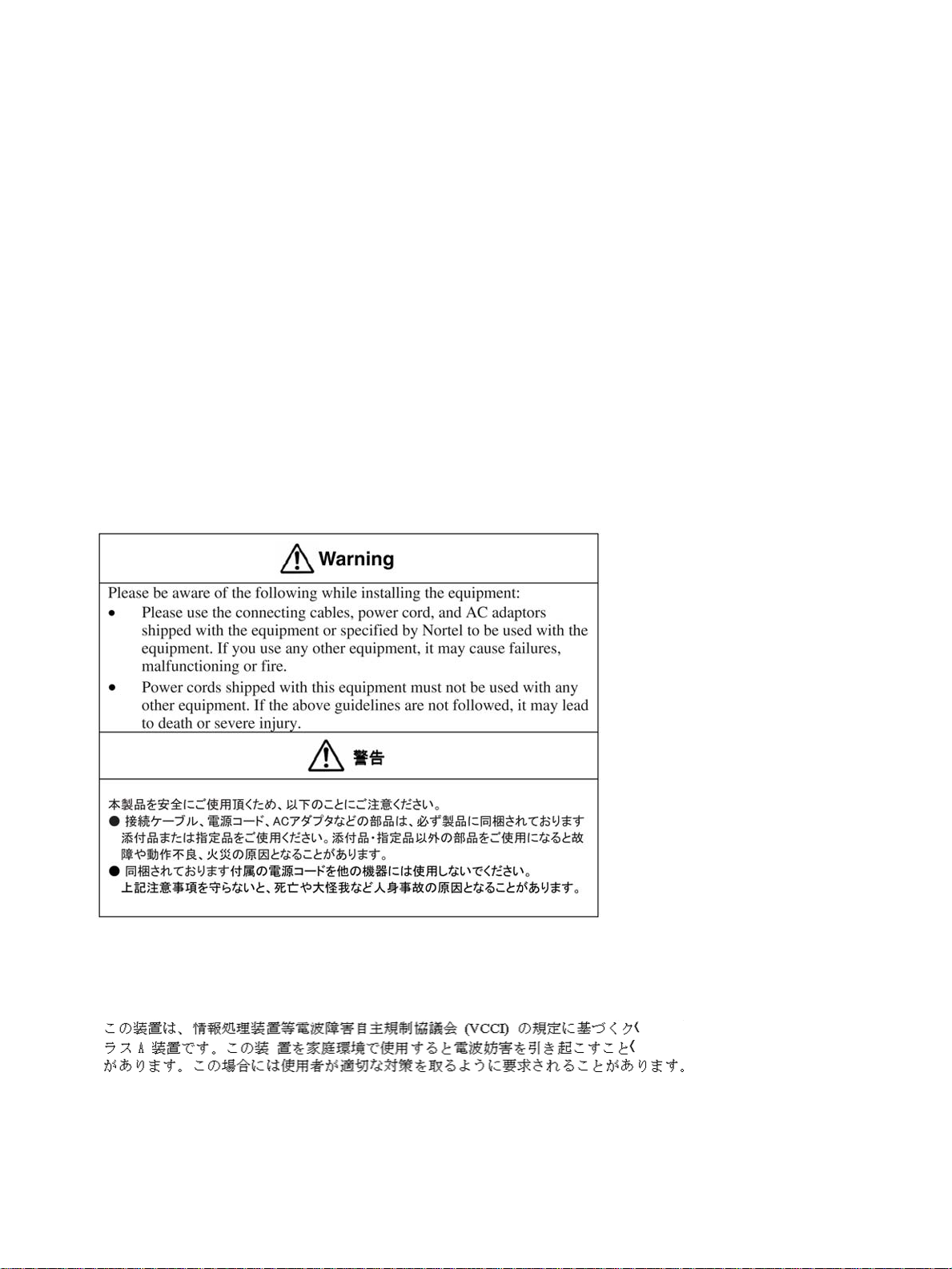
Information for Japan
Japan Denan statement
The following applies to server models 600r, 1005r, 703t, and 1002rp:
Japan VCCI statement
The following applies to server models 600r, 1005r, 703t, 201i, and 1002rp:
This is a Class A product based on the standard of the Voluntary Control Council for Interference by Information
Technology Equipment (VCCI). If this equipment is used in a domestic environment, radio disturbance may occur, in
which case, the user may be required to take corrective action.
Page 4

Page 5

Publication History
May 2008
CallPilot 5.0, Standard 01.06 of CallPilot Installation and Configuration,
1005r Server Hardware Installation is issued for general release.
May 2007
CallPilot 5.0, Standard 01.05 of CallPilot Installation and Configuration,
1005r Server Hardware Installation is issued for general release.
April 2007
CallPilot 5.0, Standard 01.04 of CallPilot Installation and Configuration,
1005r Server Hardware Installation is issued for general release.
April 2007
CallPilot 5.0, Standard 01.03 of CallPilot Installation and Configuration,
1005r Server Hardware Installation is issued for general release.
April 2007
CallPilot 5.0, Standard 01.02 of CallPilot Installation and Configuration,
1005r Server Hardware Installation is issued for general release.
5
February 2007
CallPilot 5.0, Standard 01.01 of CallPilot Installation and Configuration,
1005r Server Hardware Installation is issued for general release.
Copyright © 2006-2008, Nortel Networks
.
1005r Server Hardware Installation
Nortel CallPilot
NN44200-308 01.06 Standard
5.0 15 May 2008
Page 6

6 Publication History
Copyright © 2006-2008, Nortel Networks
.
1005r Server Hardware Installation
Nortel CallPilot
NN44200-308 01.06 Standard
5.0 15 May 2008
Page 7

Contents
Chapter 1 How to get help 9
Chapter 2 1005r server description 11
1005r Server features 11
Valid PCI card configurations 16
Network connectivity 18
Supported peripheral devices 21
Chapter 3 Preparing for installation 23
Installation overview 23
Unpacking the 1005r server 25
Removing the front bezel 27
Chapter 4 Installing the server and peripheral devices 29
Installing the server 29
Inspecting the modem 31
Connecting peripherals to the server 31
Connecting the server to the ELAN subnet 35
Connecting the server to the Nortel server subnet (optional) 36
Installing the Nortel software feature dongle 37
7
Chapter 5 Connecting the server to power 41
Safety precautions 41
Locating the power supply modules 41
Connecting the server to power 42
Appendix A EMC emission level protection for the 1005r
Server 47
Index 49
Copyright © 2006-2008, Nortel Networks
.
1005r Server Hardware Installation
Nortel CallPilot
NN44200-308 01.06 Standard
5.0 15 May 2008
Page 8

8 Contents
Copyright © 2006-2008, Nortel Networks
.
1005r Server Hardware Installation
Nortel CallPilot
NN44200-308 01.06 Standard
5.0 15 May 2008
Page 9

Chapter 1
How to get help
This section explains how to get help for Nortel products and services.
Getting Help from the Nortel Web site
The best way to get technical support for Nortel products is from the Nortel
Technical Support Web site:
w
ww.nortel.com/support
This site provides quick access to software, documentation, bulletins, and
tools to address issues with Nortel products. More specifically,
•
download software, documentation, and product bulletins
•
search the Technical Support Web site and the Nortel Knowledge Base
for answers to technical issues
•
sign up for automatic notification of new software and documentation
for Nortel equipment
9
•
open and manage technical support cases
Getting Help over the phone from a Nortel Solutions Center
If you do not find the information you require on the Nortel Technical Support
Web site, and have a Nortel support contract, you can also get help over the
phone from a Nortel Solutions Center.
In North America, call 1-800-4NORTEL (1-800-466-7835).
Outside North America, go to the following Web site to obtain the phone
number for your region:
w
ww.nortel.com/callus
Getting Help from a specialist by using an Express Routing Code
To access some NortelTechnical Solutions Centers, you can use an Express
Routing Code (ERC) to quickly route your call to a specialist in your Nortel
product or service. To locate the ERC for your product or service, go to:
Copyright © 2006-2008, Nortel Networks
.
1005r Server Hardware Installation
Nortel CallPilot
NN44200-308 01.06 Standard
5.0 15 May 2008
Page 10

10 Chapter 1 How to get help
www.nortel.com/erc
Getting Help through a Nortel distributor or reseller
If you purchased a service contract for your Nortel product from a distributor
or authorized reseller, contact the technical support staff for that distributor
or reseller.
Copyright © 2006-2008, Nortel Networks
.
1005r Server Hardware Installation
Nortel CallPilot
NN44200-308 01.06 Standard
5.0 15 May 2008
Page 11

Chapter 2
1005r server description
In this chapter
"1005r Server features" (page 11)
"Valid PCI card configurations" (page 16)
"Network connectivity" (page 18)
"Supported peripheral devices" (page 21)
"DCAM-7258188" (page 22)
1005r Server features
Introduction
The 1005r CallPilot server is a long life industrial server in a standard
rack-mount 2U form factor. It utilizes dual Xeon technology and proven,
reliable SCSI hard-drive technology.
11
This section provides a general overview of the 1005r server features.
RoHS compliance
The 1005r server meets the requirements of the Restriction of Hazardous
Substances Directive 2002/95/EC, applicable in countries affected by the
EUED (European Union Environmental Directives). RoHS requirements
impose restrictions on the type and quantity of materials used in the
manufacturing and construction of Electronic and Electrical Equipment
(EEE).
To comply with the RoHS directive, some of the part numbers now
contain an E5 or E6 suffix. For example, part number NTRH2014 is now
NTRH2014E6. The part numbers in this guide do not contain the suffix.
Copyright © 2006-2008, Nortel Networks
.
1005r Server Hardware Installation
Nortel CallPilot
NN44200-308 01.06 Standard
5.0 15 May 2008
Page 12
12 Chapter 2 1005r server description
Server dimensions and weight
Height 87.6 mm (3.45 in.)
Width 435.3 mm (17.4 in.)
Depth (distance from front to back) 508 mm (20 in.)
Weight of fully loaded system 20 kg (44 lb)
Environmental specifications
Environmental condition
Operating temperature
Non operating (storage) temperature
Non operating humidity
Altitude < 1 829 m (6 000 ft)
Electrostatic discharge <= 15 kV
Acoustic noise < 55 dBA
Handling drop (storage) 18 in free-fall (when packaged)
Handling drop 2g 11 mS
Front clearance 50.8 mm (2 in.)
Side clearance 25 mm (1 in.)
Rear clearance 92 mm (3.6 in.)
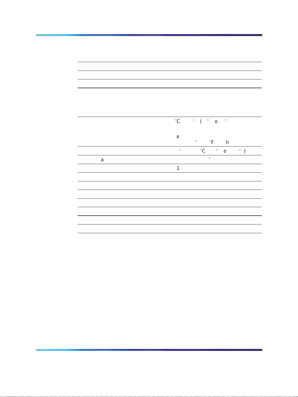
Front panel controls and features
The following diagram shows the front view of the 1005r server chassis with
the bezel cover removed. When the bezel cover is on, only the DVD and
USB connections, controls, alarm LEDs, and status LEDs are visible. With
the bezel cover removed, both hard drives, the peripheral DVD/CD/CDRW
drive, the anti-static connection, and the front serial port are accessible.
Specification
Cto35
5
Maximum rate of change must not
exceed 10
-40
95% @ 23 to 40
C (41
C (50F) per hour.
C to +70C (-40
Fto95
F to +158F)
C
F)
Copyright © 2006-2008, Nortel Networks
.
1005r Server Hardware Installation
Nortel CallPilot
NN44200-308 01.06 Standard
5.0 15 May 2008
Page 13
Front panel controls
1005r Server features 13
Label
Control or feature
A Power switch L HDD1 activity
B Reset switch M HDD0 activity
C Critical alarm LED N DVD/CD/CDRW LED and eject
D Major alarm LED O Front serial port
E Minor Alarm LED P USB 2
F Power Alarm LED Q Electrostatic Discharge (ESD)
G NMI switch (not used) R Hard drive 1 pull handle
H ID switch S Hard drive 1 release lever
I ID LED T Hard drive 0 pull handle
J NIC activity LED U Hard drive 0 release lever
K Status LED
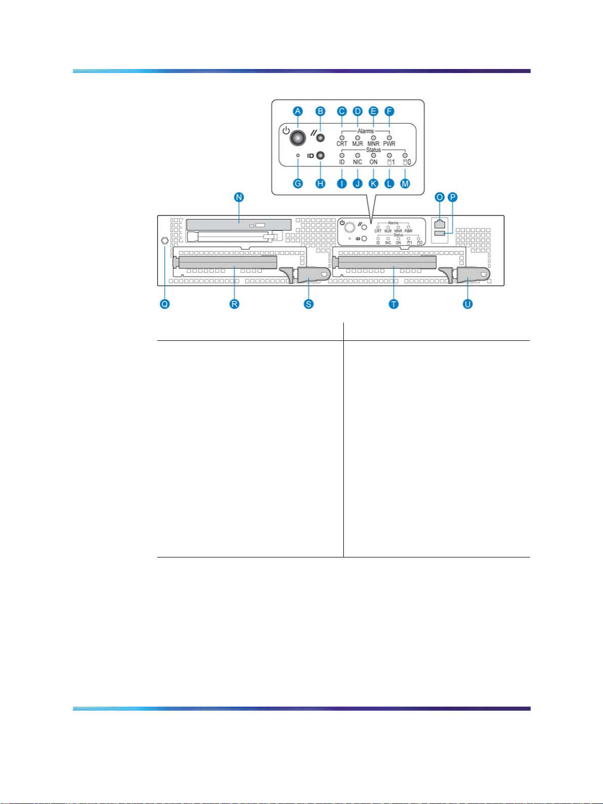
Back panel controls and features
The following diagram shows the back panel controls and features. On
the right are the AC power supply banks. The PCI card brackets are in
the middle of the back panel while the connectors and ports are along the
bottom and left side.
Label
Control or feature
button
connection
Copyright © 2006-2008, Nortel Networks
.
1005r Server Hardware Installation
Nortel CallPilot
NN44200-308 01.06 Standard
5.0 15 May 2008
Page 14
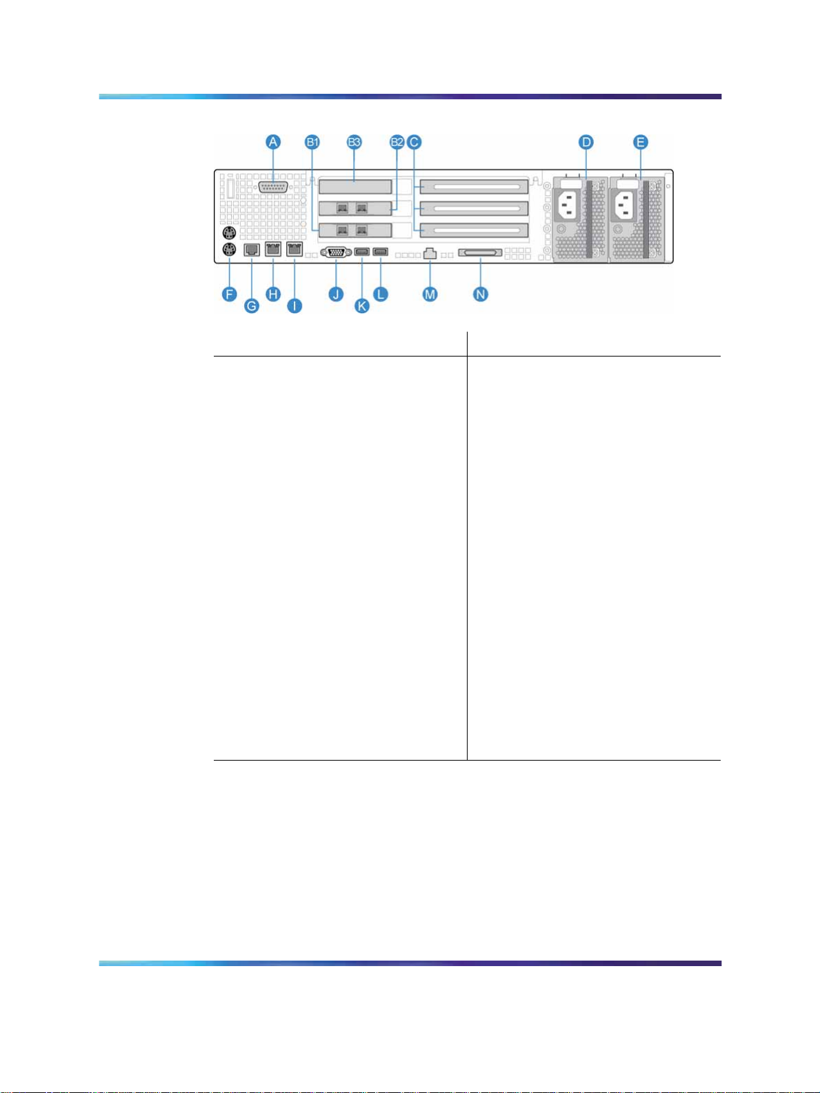
14 Chapter 2 1005r server description
Back panel controls and features
Label
Control or feature
A DB15 Telco alarm connector
(not used)
B1 PCI card #3 dual NIC for High
Label
Control or feature
G Rear connection to Comm 2
serial port
H RJ45 NIC 1 connector
Availability (HA) configuration.
For more information about
HA, see High Availability:
Installation and Configuration
(NN44200-311).
B2 PCI card #2 dual NIC for
I RJ45 NIC 2 connector
HA configuration. For more
information about HA, see High
Availability: Installation and
Configuration (NN44200-311).
B3 RAID J Video connector
C PCI full-size card brackets.
K USB 1
Numbered (1, 2, 3) from top to
bottom.
D Power Supply 1 L USB 0
E Power Supply 2 M Server management LAN port
F PS/2 mouse and keyboard
N External SCSI tape drive
connectors
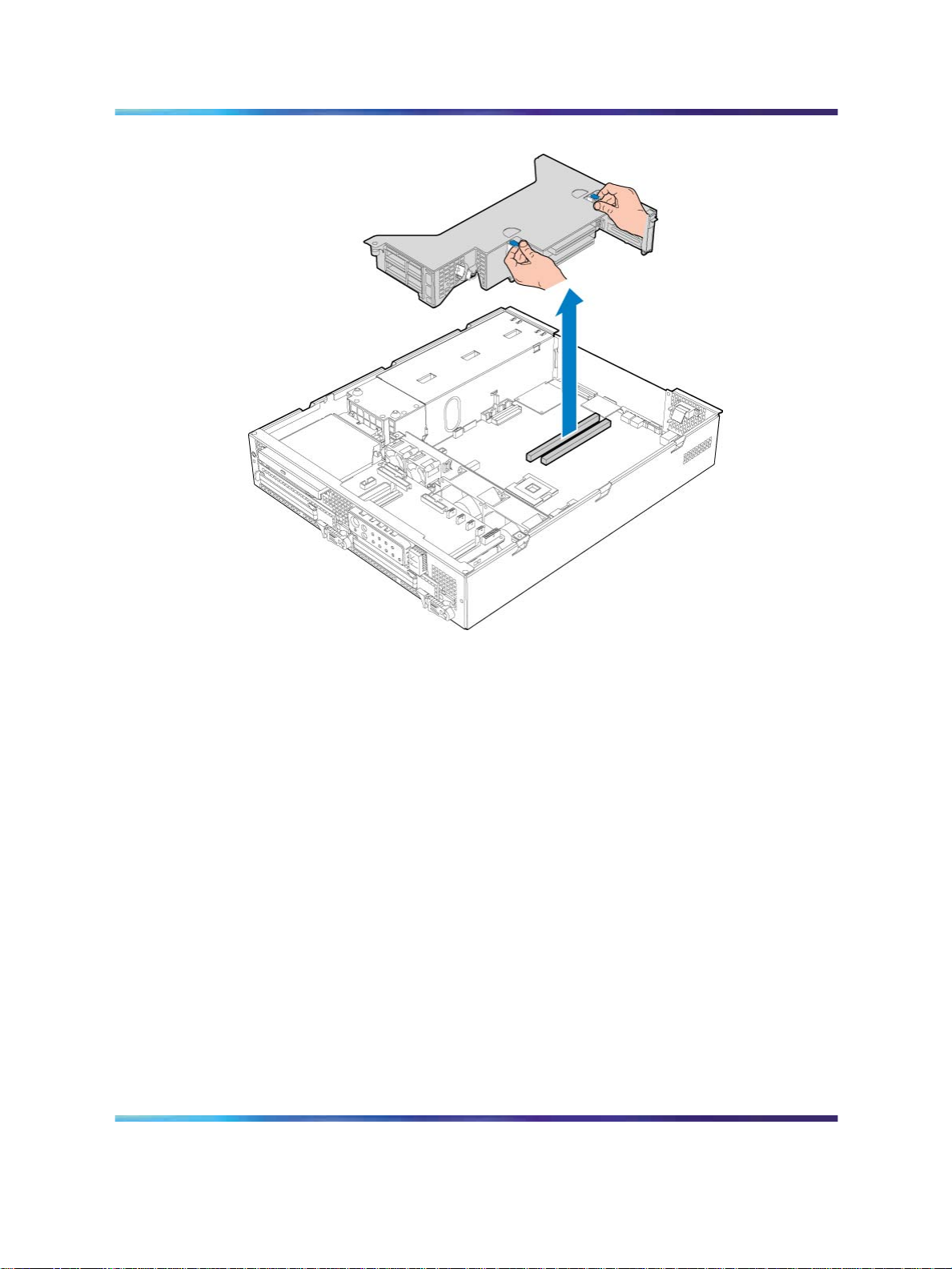
PCI riser assembly
The PCI riser assembly holds the PCI add-in cards; MPB96, RAID and
dual Network Interface Card (NIC). For more information about your
configuration, see "Valid PCI card configurations" (page 16). The following
diagram shows the PCI riser held above the server.
Copyright © 2006-2008, Nortel Networks
.
1005r Server Hardware Installation
Nortel CallPilot
NN44200-308 01.06 Standard
5.0 15 May 2008
Page 15
PCI riser card
1005r Server features 15
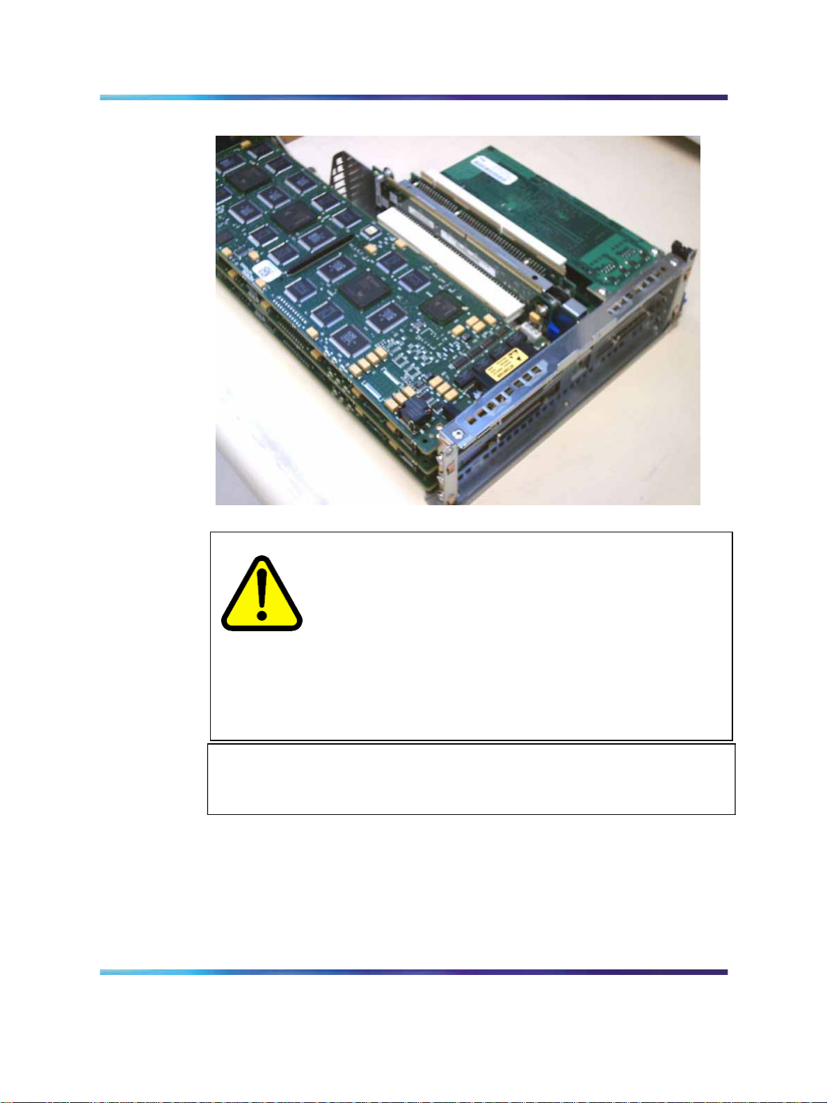
The following picture shows the PCI riser assembly when removed from the
1005r chassis. The PCI riser assembly is shown turned over with low-profile
and full-size cards installed.
Copyright © 2006-2008, Nortel Networks
.
1005r Server Hardware Installation
Nortel CallPilot
NN44200-308 01.06 Standard
5.0 15 May 2008
Page 16
16 Chapter 2 1005r server description
PCI riser card (turned over)
CAUTION
Risk of physical equipment damage
Remove the 1005r from the rack, and place it on a solid surface
when replacing or adding cards. The PCI riser assembly requires
considerable force when inserting it into the connector, and
physical damage can result if the assembly is not properly aligned.
When you place the server on a solid surface such as a
workbench, you have a better view of the card alignment, and
you can exert the necessary force when inserting the assembly
into the connector.
If The PCI riser assembly must be fully seated to avoid server malfunction.
Valid PCI card configurations
Introduction
There are six PCI card slots; three low-profile and three full-size. Valid
configurations of low-profile and full-size cards are shown in the table "1005r
PCI card slot configurations" (page 17).
ATTENTION
Copyright © 2006-2008, Nortel Networks
.
1005r Server Hardware Installation
Nortel CallPilot
NN44200-308 01.06 Standard
5.0 15 May 2008
Page 17
Valid PCI card configurations 17
Note: Your server configuration depends on what was ordered from
Nortel. Therefore, your server may not have all of the slots populated.
When looking at the server from the rear (see "Back panel controls and
features" (page 13)), both full-size and low-profile cards are numbered from
the top down.
Note: There are two MPB96 board versions; the NTRH40AA, and
NTRH40CA. The following table compares the two boards.
Version Description
NTRH40AA Has a single DB-44 connector on its faceplate
Connects to the CS 1000 or Meridian 1 with an NTRH2014 DS30X cable
NTRH40CA Has three RJ-45 connectors on its faceplate
Connects to the CS 1000 or Meridian 1 with three standard RJ-45
connectorized Ethernet cables
For more information about these cables and connecting the NTRH40CA
MPB96 board to MGate cards, see
Server Configuration (NN44200-312) or Meridian 1 and CallPilot Server
Configuration (NN44200-302).
Communication Server and CallPilot
If you have an NTRH40AA MPB96 board, you must connect the DS30X-1 cable
to an MGate card to receive the clock source for the MPB96 board. Failure to
connect the DS30X-1 cable to an MGate card can result in noise interference on
the remaining voice channels. This restriction does not apply to the NTRH40CA
MPB96 board, as it can receive clock source from any of the three DS30 ports.
1005r PCI card slot configurations
Card
slot
Configuration
Single MPB96
type
Full size
Low profile
Note: When cabling to MGate cards, the RJ-45 connectors are numbered from
1 to 3 on the NTRH40CA MPB96 board starting from the right side of the back
panel (next to the power supplies).
ATTENTION
Slot
number Position Card type
FS_PCI-1
FS_PCI-2 middle Not used
FS_PCI-3 bottom Not used
LP_PCI-1
LP_PCI-2 middle Dual NIC
LP_PCI-3 bottom Dual NIC
top
top
MPB96 MGate 1, 2, 3
RAID
Meridian 1*/
CS* 1000
Copyright © 2006-2008, Nortel Networks
.
1005r Server Hardware Installation
Nortel CallPilot
NN44200-308 01.06 Standard
5.0 15 May 2008
Page 18

18 Chapter 2 1005r server description
Card
Configuration
Three MPB96
(High Capacity)
slot
type
Full size
Note: 3 Mgate cards connect to 1 MPB96
When cabling to MGate cards, the RJ-45 connectors are numbered from 1 to 3
on the top NTRH40CA MPB96 board and from 4 to 6 on the middle NTRH40CA
MPB96 board starting from the right side of the back panel (next to the power
supplies)
Low profile
Slot
number Position Card type
FS_PCI-1
FS_PCI-2 middle MPB96 MGate 4, 5, 6
FS_PCI-3 bottom MPB96
LP_PCI-1
LP_PCI-2 middle Dual NIC
LP_PCI-3 bottom Dual NIC
Network connectivity
Introduction
This section describes how the 1005r server can be integrated into your
network. The integration depends on the type of switch you are using.
top
top
Meridian 1*/
CS* 1000
MPB96 MGate 1, 2, 3
RAID
To secure the CallPilot server from unauthorized access, ensure that the CallPilot
network is inside your organization’s firewall.
Sample network setup: Meridian 1
The following diagram shows a CallPilot server sample network setup with a
Meridian 1 switch. The Meridian 1 switch can be one of the following:
•
Option 11C or Option 11C Mini
•
Option 51C
•
Option 61C
•
Options 81 and 81C
ATTENTION
Copyright © 2006-2008, Nortel Networks
.
1005r Server Hardware Installation
Nortel CallPilot
NN44200-308 01.06 Standard
5.0 15 May 2008
Page 19

Sample network setup: Communication Server 1000
The following diagram shows a CallPilot server network setup with a
Communication Server 1000 (CS 1000) system.
Network connectivity 19
Copyright © 2006-2008, Nortel Networks
.
1005r Server Hardware Installation
Nortel CallPilot
NN44200-308 01.06 Standard
5.0 15 May 2008
Page 20

20 Chapter 2 1005r server description
In the previous illustration, the telephony LAN (TLAN subnet) provides
IP connectivity between the CS 1000 system and the i2004 Internet
phonesets. The connection between the call server and media gateway
can be point-to-point (or through the LAN), if the system is installed in
a distributed data network.
For information about the CS 1000 system and i2004 Internet phoneset
bandwidth and network requirements, refer to the Communication Server for
Enterprise 1000 Planning and Installation Guide (553-3023-210).
Switch connectivity
For more details about how the 1005r server and switch connection
is established, refer to the Installation and Configuration Task List
(NN44200-306).
CallPilot ELAN subnet and Nortel server subnet setup
The 1005r server provides 10/100/1000Base-T Ethernet connectivity
through NICs installed in the server. The function of the NIC varies based
on switch connectivity, as follows:
Meridian 1 or CS 1000 systems
•
One NIC provides connectivity to the ELAN subnet. Connect the NIC
labeled NIC2-NickP on the back of the server to the ELAN subnet.
For information about the purpose and requirements of the ELAN
subnet, see the Planning and Engineering Guide (NN44200-200).
•
The second NIC, labeled NIC1-NickP can be connected to the Nortel
server subnet.
This optional NIC is required only for Meridian 1 or CS 1000 systems
that require a Nortel server subnet connection (in addition to the
ELAN subnet connection). The Nortel server subnet provides data
connectivity between desktop and Web messaging clients, Web-enabled
administrative PCs, and the CallPilot server.
Network requirements
Appropriate networking equipment must be available for both the Nortel
server subnet and ELAN subnet.
The Nortel server subnet and ELAN subnet must be properly configured
for correct CallPilot operation. To ensure correct configuration, Nortel
recommends that you consult a network specialist.
Copyright © 2006-2008, Nortel Networks
.
1005r Server Hardware Installation
Nortel CallPilot
NN44200-308 01.06 Standard
5.0 15 May 2008
Page 21

Supported peripheral devices 21
Remote access connectivity
Use one of the USB connectors on the rear of the 1005r server to connect
to an external plug-and-play modem. The modem is used for remote
administration and technical support.
RRAS is used to establish the remote access connection to the server. Use
either RDC or pcAnywhere to communicate with the CallPilot server.
Supported peripheral devices
Introduction
This section identifies external devices that are supported by the 1005r
server.
Device Description
Modem Use a 56-Kb/s external modem to provide remote access to the 1005r
server. The modem connects to one of the USB connectors on the
rear of the server. You cannot use a serial port modem.
Ethernet switch or hub
A 10Base-T Ethernet switch or hub provides the ELAN subnet
connection between the 1005r server and the Meridian 1 switch or
CS 1000 system. The customer can supply an Ethernet hub or
switch from third-party vendors or from Nortel.
Monitor, keyboard, and
mouse
Tape drive
Since the Ethernet switch or hub is an external device, it requires
an AC power source.
ATTENTION
To comply with EMC radiation requirements, a Class A Ethernet
hub or switch must be located 10 m (33 ft) away from the 1005r
server. Shielded Ethernet cables must be used.
•
VGA Monitor with Male DB-15 connector (customer supplied)
Since the monitor is an external device, it requires its own AC
power source.
• Keyboard: (customer supplied)
•
Mouse: (customer supplied)
•
Use an external SCSI tape drive to back up your system. The
Tandberg SLR 75 can be ordered with your system.
Copyright © 2006-2008, Nortel Networks
.
1005r Server Hardware Installation
Nortel CallPilot
NN44200-308 01.06 Standard
5.0 15 May 2008
Page 22

22 Chapter 2 1005r server description
Copyright © 2006-2008, Nortel Networks
.
1005r Server Hardware Installation
Nortel CallPilot
NN44200-308 01.06 Standard
5.0 15 May 2008
Page 23

Chapter 3
Preparing for installation
In this chapter
•
"Installation overview" (page 23)
•
"Unpacking the 1005r server" (page 25)
• "Removing the front bezel" (page 27)
Installation overview
Introduction
This section provides an overview of the steps required to install the 1005r
server and peripheral devices.
Installation checklist
The following checklist identifies the tasks that must be performed when
installing the CallPilot server. For detailed instructions, see "Installing the
server" (page 29) When you are finished with the installation, continue with
the Installation and Configuration Task List (NN44200-306).
23
Note: If you are installing a High Availability system, follow this
checklist for each server, with the exceptions listed on "Installing a High
Availability system" (page 30)
Step
1
Copyright © 2006-2008, Nortel Networks
.
Description
Review the "Installing the CallPilot server" section in the Installation
and Configuration Task List (NN44200-306), and completed stage
1 of the "Installation checklist."
Check
Nortel CallPilot
1005r Server Hardware Installation
NN44200-308 01.06 Standard
5.0 15 May 2008
Page 24

24 Chapter 3 Preparing for installation
Step
2
3
4
5
6
Description
Unpack the server, and ensure you have all the items you need (see
"Unpacking the 1005r server" (page 25)).
Complete the following checklists that are provided in the Installation
and Configuration Task List (NN44200-306):
• "CallPilot software media and documentation checklist"
•
"CallPilot server hardware checklist"
Remove the front bezel and inspect the front panel (see pages
"Removing the front bezel" (page 27)).
Place the 1005r server in the chosen location (see "Installing the
server" (page 29)).
Replace the front bezel (see page "To replace the front bezel" (page
30)).
Connect the 1005r server and devices as follows:
• Connect the monitor, keyboard, and mouse (see "Connecting
peripherals to the server" (page 31)).
•
Connect the modem (see "To connect the modem to the server"
(page 33)).
•
Connect the 1005r server to the ELAN Ethernet switch or hub
(Meridian 1 or CS 1000 only) (see "Connecting the server to the
ELAN subnet" (page 35)).
Check
To comply with EMC radiation requirements, a Class A Ethernet
switch or hub must be located 10 m (33 ft.) away from the 1005r
server. Shielded Ethernet cables must be used.
Note: If you are connecting the optional Nortel server subnet, do not
power up unless your antivirus programs and Nortel security updates
are installed first.
•
Connect the 1005r server to the Nortel server subnet Ethernet
switch or hub (optional) (see "Connecting the server to the Nortel
server subnet (optional)" (page 36)).
To comply with EMC radiation requirements, a Class A Ethernet
switch or hub must be located 10 m (33 ft.) away from the 1005r
server. Shielded Ethernet cables must be used.
Copyright © 2006-2008, Nortel Networks
.
ATTENTION
ATTENTION
Nortel CallPilot
1005r Server Hardware Installation
NN44200-308 01.06 Standard
5.0 15 May 2008
Page 25

Unpacking the 1005r server 25
Step
7
Description
•
Install the software feature dongle (see "Installing the Nortel
software feature dongle" (page 37)).
•
Connect the power cords for all devices, and then power them up.
Start the 1005r server (see "To start the server" (page 44)).
Conventions for warnings
You could encounter the following types of warnings in this guide. Do not
ignore them.
DANGER
Risk of electric shock
Warns you of an immediate electrical hazard which, if not avoided,
can result in shock, serious injury, or death.
WARNING
Risk of personal injury
Warns you of a situation in which you can be injured if instructions
are not followed exactly as stated.
Check
CAUTION
Risk of equipment damage
Alerts you to situations where data can be lost or damaged,
equipment can be damaged, actions can result in service
interruption, and productive time can be lost.
Provides information that is essential to the completion of a task.
Unpacking the 1005r server
Introduction
Follow this procedure to unpack the server and peripherals.
1005r Server Hardware Installation
NN44200-308 01.06 Standard
Copyright © 2006-2008, Nortel Networks
.
ATTENTION
Nortel CallPilot
5.0 15 May 2008
Page 26

26 Chapter 3 Preparing for installation
WARNING
Risk of personal injury
The 1005r CallPilot server weighs approximately 20 kg (44 lb)
when it is shipped from manufacturing. To prevent personal injury,
have someone help you to unpack and position the server.
To unpack the equipment
Step Action
As you unpack each item, check it off against the packing list, as well as against
the following checklists provided in the
(NN44200-306):
•
"CallPilot software media and documentation checklist"
•
"CallPilot server hardware checklist"
ATTENTION
Installation and Configuration Task List
1
2
3
4
5
6
What is next?
Remove the front bezel cover so that you can inspect the front panel of the
server. See "Removing the front bezel" (page 27).
Open the cardboard carton containing the server.
Remove the server from the carton; set it on a secure surface.
Open the cartons containing the monitor, keyboard, mouse,
modem, and ELAN Ethernet switch or hub (if supplied), and set the
peripherals aside.
Remove the dongle from the box and set it aside
Put all manuals, DVDs or CDs, operating system disks, and any
disks for peripherals in a safe place.
Save all packing materials and cartons in case you must return any
equipment to the carrier.
—End—
Copyright © 2006-2008, Nortel Networks
.
1005r Server Hardware Installation
Nortel CallPilot
NN44200-308 01.06 Standard
5.0 15 May 2008
Page 27

Removing the front bezel
Introduction
To access the hard drives on the front panel, you must remove the front
bezel.
The front bezel covers the electrostatic discharge (ESD) connection, both
hard drives, and the DVD/CD/CDRW drive pull handle. The control panel,
USB port 2, and the front comm 2 serial port connection are not covered by
the front bezel.
To remove the front bezel
Step Action
CAUTION
Risk of equipment damage
Do not attempt to move or lift the server before removing the front
bezel; the server can disengage from the bezel and fall.
Removing the front bezel 27
1
Loosen the two black captive fasteners on either side of the front
bezel.
2
Pull the front bezel off the front panel by the captive fasteners.
Copyright © 2006-2008, Nortel Networks
.
1005r Server Hardware Installation
Nortel CallPilot
NN44200-308 01.06 Standard
5.0 15 May 2008
Page 28

28 Chapter 3 Preparing for installation
3
What is next?
Continue with Chapter 5 " Connecting the server to power" (page 41).
Do not touch components on the front panel without ESD protection.
Attach an ESD strap to your wrist and connect it to a single point
ground connection.
—End—
Copyright © 2006-2008, Nortel Networks
.
1005r Server Hardware Installation
Nortel CallPilot
NN44200-308 01.06 Standard
5.0 15 May 2008
Page 29

Chapter 4
Installing the server and peripheral
devices
In this chapter
"Installing the server" (page 29)
"Installing a High Availability system" (page 30)
"Inspecting the modem" (page 31)
"Connecting peripherals to the server" (page 31)
"Connecting the server to the ELAN subnet" (page 35)
"Connecting the server to the Nortel server subnet (optional)" (page 36)
29
"Installing the Nortel software feature dongle" (page 37)
Installing the server
Introduction
Before you install the 1005r server, ensure that the chosen location meets
the requirements identified on the "Site inspection checklist" provided in the
Installation and Configuration Task List (NN44200-306).
To install the server
Place the 1005r server in its chosen location. If you are installing the server
in a rack cabinet, follow the instructions provided with the slide rails.
Copyright © 2006-2008, Nortel Networks
.
WARNING
Do not connect the server to the power yet.
Nortel CallPilot
1005r Server Hardware Installation
NN44200-308 01.06 Standard
5.0 15 May 2008
Page 30

30 Chapter 4 Installing the server and peripheral devices
ATTENTION
The 1005r server is supplied with industry standard 48.3 cm (19 in.) rack rails that
can accommodate racks with a maximum depth of 61 cm (24 in.) between the
mounting posts. Check the rack you are using and ensure that the Nortel supplied
server rack rails are suitable for your specific installation requirements. For depths
greater than 61 cm (24 in.), Nortel recommends that you purchase a third-party
rack shelf that can safely hold up to 34 kg (75 lb.).
To replace the front bezel
Step Action
When the CallPilot server is in its final location, replace the front bezel.
1 Align the front bezel with the captive fasteners on either side of the
front bezel with the threaded holes in the front panel.
2
Tighten the captive fasteners by hand.
What is next?
Connect peripheral devices as described in the remainder of this chapter.
Installing a High Availability system
The High Availability configuration is only supported on the 1005r platform.
In a High Availability configuration, a pair of peer CallPilot 1005r servers is
used in the place of a single server. Both servers are connected to the
same switch and are configured so that one CallPilot server is active (that
is, processing calls) and the other is standing by, ready to take over for the
first server if the active server fails due to a pre-determined failure condition.
The High Availability feature supports both automatic failovers, where the
software detects an error condition and triggers a failover to the standby
server, and manual failovers which are administrator initiated.
For a High availability system, Nortel recommends that you install both
servers on the same rack, preferably one server directly below the other.
This allows for greater ease in administration. Clearly label each server
for easy identification.
—End—
Follow the installation procedures in this document for each server, with the
following exceptions:
•
Do not connect the server to the Nortel Server Subnet, or the ELAN
subnet until directed to do so in the Server and Switch Configuration
guide.
Copyright © 2006-2008, Nortel Networks
.
1005r Server Hardware Installation
Nortel CallPilot
NN44200-308 01.06 Standard
5.0 15 May 2008
Page 31

•
The two servers are delivered with only one dongle. It does not matter
which server you connect the dongle to until you configure the servers.
For more information about the High Availability feature, see High
Availability: Installation and Configuration (NN44200-311).
Inspecting the modem
Introduction
You require a modem to support remote dial-up access to the CallPilot
server. Nortel technical support also connects to your CallPilot server for
troubleshooting purposes. Nortel connects to your server only when you
request technical assistance.
Required equipment
To install the modem, you need the following equipment:
•
USB modem
•
RJ-11 analog phone cord
•
USB cable (supplied with the modem)
Connecting peripherals to the server 31
•
analog line jack
Serial port modems with RS-232 connections are not supported on the
1005r.
What is next?
Continue with "Connecting peripherals to the server" (page 31).
Connecting peripherals to the server
Rear panel connectors
The following diagram shows the connectors on the rear panel.
Label
A DB15 Telco alarm connector
Copyright © 2006-2008, Nortel Networks
.
Control or feature
(not used)
Label
G Rear connection to Comm 2
Nortel CallPilot
1005r Server Hardware Installation
NN44200-308 01.06 Standard
5.0 15 May 2008
Control or feature
serial port
Page 32

32 Chapter 4 Installing the server and peripheral devices
Label
B1 PCI card #3 dual NIC for
B2 PCI card #2 dual NIC for High
B3 RAID J Video connector
C PCI full-size card brackets.
D Power Supply 1 L USB 0
E Power Supply 2 M Server management LAN port
F PS/2 mouse and keyboard
Control or feature
HA configuration. For more
information about HA, see High
Availability: Installation and
Configuration (NN44200-311).
Availability (HA) configuration.
For more information about
HA, see High Availability:
Installation and Configuration
(NN44200-311).
Numbered (1, 2, 3) from top to
bottom.
connectors
Label
H RJ45 NIC 1 connector
I RJ45 NIC 2 connector
K USB 1
N External SCSI tape drive
Control or feature
To connect the mouse, keyboard, and monitor to the server
Step Action
1
2
3
4
5
6
Place the monitor, keyboard, and mouse in the same location as
the server.
Plug the keyboard and mouse cables into the PS/2 connectors on
the rear panel (see "Rear panel connectors" (page 31)).
Plug the monitor into the video connector on the rear panel. Tighten
the screws on the connector.
Ensure that a single-point ground reference is available for all
the power outlets serving the CallPilot server and its peripherals.
Before the CallPilot server installation, a qualified electrician must
implement the single-point ground reference requirement between
the power outlets of the CallPilot server and the power outlets of
the switch.
Connect the power cord to the monitor and plug the other end into
a wall receptacle or power bar.
Turn on the monitor.
Copyright © 2006-2008, Nortel Networks
.
—End—
Nortel CallPilot
1005r Server Hardware Installation
NN44200-308 01.06 Standard
5.0 15 May 2008
Page 33

Connecting peripherals to the server 33
To connect the modem to the server
Step Action
1 Connect one end of the telephone cable to the modem RJ-11 jack
labeled LINE.
2
Connect the other end of the telephone cable to the RJ-11 jack in
the wall.
3 Connect one end of the USB cable into the modem.
4
Connect the other end of the USB cable into either USB port 1 on the
rear panel (long term) or USB port 2 on the front panel (short term).
—End—
To connect the external SCSI tape drive
Step Action
Note : The external SCSI tape drive is a plug and play device. For a High
availability system you may wish to share one tape drive between the two
servers.
1
2
Set the SCSI ID dial switch on the tape drive to SCSI ID 6.
With the power switch off, connect the external SCSI tape drive to
the port labeled N on the rear panel. See "Rear panel connectors"
(page 31).
3
Plug the tape drive into the same single-point ground and A/C power
as the rest of the system.
4
Make sure the SCSI terminator is connected to the tape drive before
powering on the tape drive.
5
Copyright © 2006-2008, Nortel Networks
.
Power on the tape unit.
1005r Server Hardware Installation
Nortel CallPilot
NN44200-308 01.06 Standard
5.0 15 May 2008
Page 34

34 Chapter 4 Installing the server and peripheral devices
SLR75 tape drive installed on 1005r
6
7
8
What is next?
Continue with "Connecting the server to the ELAN subnet" (page 35).
The tape drive is plug-and-play and the required drivers are already
installed on your system.
You must run the device scan initiation in device manager to detect
the drive.
a. Choose Start → My Computer →Properties →Hardware →
Device Manager from the desktop.
b. Select Action → Scan for Hardware changes.
The tape drive is ready for use.
—End—
Copyright © 2006-2008, Nortel Networks
.
1005r Server Hardware Installation
Nortel CallPilot
NN44200-308 01.06 Standard
5.0 15 May 2008
Page 35

Connecting the server to the ELAN subnet 35
Connecting the server to the ELAN subnet
Introduction
Connect the CallPilot server to the Meridian 1 switch or CS 1000 system
using the ELAN subnet.
Note: If you are installing a High Availability system, do not connect
either sever to the ELAN subnet. The connection to the ELAN subnet is
made when you configure the system.
ATTENTION
For important considerations about using the ELAN subnet in your network, see
the Planning and Engineering Guide (NN44200-200).
ATTENTION
To comply with EMC radiation requirements, a Class A Ethernet switch or hub
must be located 10 m (33 ft.) away from the 1005r server. You must use shielded
Ethernet cables.
To connect the server to the ELAN subnet
Step Action
1
See the diagram on page "Rear panel connectors" (page 31) to
locate the ELAN Ethernet connector.
2
Connect an RJ-45 network cable from the ELAN Ethernet switch or
hub to the ELAN connector on the server.
Note: The ELAN Ethernet switch or hub is optional if you use
a cross-over network cable to make a direct point-to-point
connection from the server to the switch. However, if you choose
to establish a direct point-to-point ELAN connection, no other
device can connect to the ELAN subnet.
3
At the switch, connect the ELAN network cable to the ELAN Ethernet
interface. Complete the connection from the transceiver to the
switch.
DANGER
Risk of fire hazard
Do not install a Media Access Unit (MAU) in ducts,
plenums, or other spaces used for environmental air. Do
not install a MAU above a false ceiling or below a raised
floor, unless you can confirm that these spaces are not
used to convey environmental air.
Copyright © 2006-2008, Nortel Networks
.
1005r Server Hardware Installation
Nortel CallPilot
NN44200-308 01.06 Standard
5.0 15 May 2008
Page 36

36 Chapter 4 Installing the server and peripheral devices
—End—
What is next?
IF the server is THEN
connected to a Nortel server subnet continue with "Connecting the server
to the Nortel server subnet (optional)"
(page 36).
not connected to a Nortel server subnet continue with installing the software
feature dongle. See "Installing the
Nortel software feature dongle" (page
37).
Connecting the server to the Nortel server subnet (optional)
Introduction
This section provides instructions to connect the server to the Nortel server
subnet.
Note 1: The Nortel server subnet is optional. However, it is required to
support desktop and Web messaging users.
Note 2: If you are installing a High Availability system, do not connect
either sever to the Nortel Server Subnet. The connection to the Nortel
Server Subnet is made when you configure the system.
ATTENTION
To comply with EMC radiation requirements, a Class A Ethernet switch or hub
must be located 10 m (33 ft.) away from the 1005r server. Shielded Ethernet
cables must be used.
To connect the server to the Nortel server subnet
Step Action
1
2
See the diagram on page "Rear panel connectors" (page 31) to
locate the CLAN connection.
Connect an RJ-45 network cable from the Nortel server subnet
Ethernet switch or hub to the CLAN connector.
—End—
Copyright © 2006-2008, Nortel Networks
.
1005r Server Hardware Installation
Nortel CallPilot
NN44200-308 01.06 Standard
5.0 15 May 2008
Page 37

Installing the Nortel software feature dongle 37
What is next?
Continue with "Installing the Nortel software feature dongle" (page 37).
Installing the Nortel software feature dongle
Introduction
The software feature key is a security device that stores the unique serial
number of the server. The feature key is embedded in the Nortel software
feature dongle, which plugs into USB port 0 on the rear panel.
Note: Only one dongle is shipped with a pair of High Availability
servers. It doesn’t matter which server you install the dongle in until
you configure the servers later on.
The following diagram shows the dongle plugged into the back panel of the
server:
Dongle installed on the server.
To install the software feature dongle
Step Action
1
2
Copyright © 2006-2008, Nortel Networks
.
Ensure that there is nothing plugged into USB port 0 on the rear
panel.
If the software feature key is not preinstalled in the dongle, insert
it into the software feature slot on the dongle. Insert the software
1005r Server Hardware Installation
Nortel CallPilot
NN44200-308 01.06 Standard
5.0 15 May 2008
Page 38

38 Chapter 4 Installing the server and peripheral devices
feature key with the data contact facing down and away from the
embossed i. See "Installing the. feature key." (page 38).
Dongle without feature key
3
To eject a software feature key, insert a straightened paper clip into
the side access hole.
a. Push the paper clip in the direction of the software feature key.
Note: In the following figure, label 1 is the data contact, and
label 2 is the ground.
Installing the. feature key.
4
Copyright © 2006-2008, Nortel Networks
.
Plug the dongle into USB port 0 on the rear panel of the server.
Note: Due to system driver allocations, the dongle must be
installed in USB port 0.
—End—
Nortel CallPilot
1005r Server Hardware Installation
NN44200-308 01.06 Standard
5.0 15 May 2008
Page 39

Installing the Nortel software feature dongle 39
What is next?
Continue with Chapter 5 " Connecting the server to power" (page 41).
Copyright © 2006-2008, Nortel Networks
.
1005r Server Hardware Installation
Nortel CallPilot
NN44200-308 01.06 Standard
5.0 15 May 2008
Page 40

40 Chapter 4 Installing the server and peripheral devices
Copyright © 2006-2008, Nortel Networks
.
1005r Server Hardware Installation
Nortel CallPilot
NN44200-308 01.06 Standard
5.0 15 May 2008
Page 41

Chapter 5
Connecting the server to power
In this chapter
•
"Safety precautions" (page 41)
•
"Locating the power supply modules" (page 41)
• "About the power supply module" (page 42)
•
"Connecting the server to power" (page 42)
Safety precautions
Equipment handling guidelines
External power equipment, such as an uninterruptible power supply (UPS),
is usually very heavy. This equipment requires special handling procedures
and additional personnel for unloading and installation. Be aware of weight
distribution, and prevent the equipment room floor from being overly
stressed.
41
Safety information
DANGER
Risk of electric shock
Procedures involving electrical connections must only be
performed by qualified personnel.
Ensure that you obey all displayed warning notices on power
equipment and connections.
Locating the power supply modules
Introduction
Both AC power supply modules are installed prior to shipping. The following
diagram shows the location of the power supply modules in the rear panel
(D and E):
1005r Server Hardware Installation
NN44200-308 01.06 Standard
Copyright © 2006-2008, Nortel Networks
.
Nortel CallPilot
5.0 15 May 2008
Page 42

42 Chapter 5 Connecting the server to power
1005r rear panel
About the power supply module
After you power up the server (later in this guide), the power supply module
LED indicates its status.
A green LED on each power supply module indicates that the modules are
working properly. If the LEDs are unlit or red, the module is failing or has
failed. A problem with a power supply module is also indicated if the PWR
or MJR LED on the front of the server turns red.
Rack power and grounding
To ensure a complete power and grounding installation:
•
In rack-mount server installations, ensure the CallPilot server chassis
and equipment racks are isolated from other foreign sources of ground.
Acceptable isolation methods include: isolation pads, grommeted
washers, chassis side-rail strips, and nonconducting washers.
•
In rack-mount server installations where other equipment is also
installed in the same rack, ensure that all equipment derives ground
from the same service panel as CallPilot and the switch.
Connecting the server to power
Before you begin
Ensure that proper power and grounding are available for all the power
outlets serving the CallPilot server and its associated peripherals. Power
for these devices must be wired and fused independently of all other
receptacles, and referenced to the same ground as the PBX system.
A qualified electrician must implement the single-point ground reference as
required between the power outlets of the CallPilot server and the power
outlets of the switch.
Copyright © 2006-2008, Nortel Networks
.
1005r Server Hardware Installation
Nortel CallPilot
NN44200-308 01.06 Standard
5.0 15 May 2008
Page 43

Connecting the server to power 43
Provide a sufficient number of properly grounded power outlets or power
bars for all equipment. For more information, refer to grounding and power
requirements in this document and in the Planning and Engineering Guide
(NN44200-200).
The single-point ground (SPG) required by the system can be an isolated
ground (IG) bus or AC equipment ground (ACEG) bus in the service panel or
transformer. The system must be connected to safety ground or protective
earth in accordance with NEC requirements. For international use, the
system must be connected to safety ground/protective earth in accordance
with Paragraph 2.5 of EN60950/IEC950.
Note: See Large System: Planning and Engineering (553-3021-120)
for a complete description of approved ground sources and methods.
Insulated ground wire must be used for system grounding.
Before you connect the server to the power source, review the following
diagram to ensure that all peripheral hardware devices are in place.
1005r server in a network.
Copyright © 2006-2008, Nortel Networks
.
1005r Server Hardware Installation
Nortel CallPilot
NN44200-308 01.06 Standard
5.0 15 May 2008
Page 44

44 Chapter 5 Connecting the server to power
To connect the 1005r AC server to power
Step Action
WARNING
Risk of personal injury, risk of hardware failure
The power outlets used by the CallPilot server and its peripheral
devices must be connected to the same single-point ground
reference as the one used by the switch with MGate cards
connected to the CallPilot server. If this requirement is not
met, power transients can cause personal injury, hardware
failure, or both. See the
(NN44200-306) for more information about single-point grounding
requirements.
Installation and Configuration Task List
1
2
Plug the server AC power cords into the server rear panel.
Plug the other ends into an approved wall receptacle or power bar.
To start the server
Step Action
1
2
3
4
Press the server power switch to start the server.
Observe the Power-On Self Test (POST) and initialization messages
on the monitor.
Let the mini-setup sequence run until you are prompted to log on
to the operating system.
Note: The system can perform multiple reboots. This is normal.
Ensure that the operating system logon window appears on the
monitor.
—End—
5
6
Copyright © 2006-2008, Nortel Networks
.
Log into Windows.
CallPilot Manager wizard starts automatically.
Note: If the logon window does not appear, see the 1005r
Server Maintenance and Diagnostics (NN44200-704) guide for
troubleshooting instructions.
Nortel CallPilot
1005r Server Hardware Installation
NN44200-308 01.06 Standard
5.0 15 May 2008
Page 45

Connecting the server to power 45
7
Use the wizard to configure your system. For further details, see the
Installation and Configuration Task List (NN44200-306).
—End—
Copyright © 2006-2008, Nortel Networks
.
1005r Server Hardware Installation
Nortel CallPilot
NN44200-308 01.06 Standard
5.0 15 May 2008
Page 46

46 Chapter 5 Connecting the server to power
Copyright © 2006-2008, Nortel Networks
.
1005r Server Hardware Installation
Nortel CallPilot
NN44200-308 01.06 Standard
5.0 15 May 2008
Page 47

Appendix A
EMC emission level protection for the
1005r Server
To lower the EMC emission level, ferrite cores are installed with one loop
(see the following diagram) on the following external cables:
•
Ferrite Core (TDK and part number ZCAT3035-1330)—for the triple
DS30X I/O cable (Nortel and part number NTRH2014E6). There are
three ferrite cores at each end of the cable.
CAUTION
Risk of equipment damage
The ferrite cores are preinstalled on the provided cables. It is not
your responsibility to attach these ferrite cores to these cables.
However, you must ensure that these ferrite cores are in place to
keep the EMC emission levels low.
47
Copyright © 2006-2008, Nortel Networks
.
1005r Server Hardware Installation
Nortel CallPilot
NN44200-308 01.06 Standard
5.0 15 May 2008
Page 48

48 Appendix A EMC emission level protection for the 1005r Server
Ferrite cores secured to an external cable
The ferrite cores are secured to the appropriate cable with plastic enclosure
clips. Tie wraps are added to the cable loop.
Copyright © 2006-2008, Nortel Networks
.
1005r Server Hardware Installation
Nortel CallPilot
NN44200-308 01.06 Standard
5.0 15 May 2008
Page 49

Index
49
Symbols/Numerics
1005r server
back panel 13
dimensions and weight 12
ELAN
connection, establishing 35
environmental specifications 12
front bezel
removing 27
replacing 30
front panel 12
installing 29
PCI card slots 16
PCI riser assembly 14
peripheral devices, supported 21
power connection, establishing 42
starting 44
C
checklist, installation 23
CLAN
media access control address 36
connecting peripherals to the server 31
connecting the server 42
connectivity
Ethernet 20
remote 21
copyright 2
CS 1000 and CallPilot server network
diagram 19
Customer LAN
see CLAN 36
D
devices, peripheral
Ethernet hub 21
keyboard 21
modem 21
monitor 21
mouse 21
diagram
1005r server in network 43
back panel 13, 31, 42
slot locations 13
connection
network, CS 1000 and CallPilot
server 19
network, M1 and CallPilot server 18
dongle
installed 37
installing 38
without feature key 38
front bezel 27
front panel 13
PCI and ISA connectors 14
PCI riser 14, 15
server connections for the power cord
and peripherals 31
SLR75 tape drive 34
dimensions, 1005r server 12
dongle 37
installing 37
E
ELAN
connecting to the server 35
Copyright © 2006-2008, Nortel Networks
.
1005r Server Hardware Installation
Nortel CallPilot
NN44200-308 01.06 Standard
5.0 15 May 2008
Page 50

50 Index
environmental specifications 12
equipment
unpacking 26
Ethernet hub
description 21
F
fax modem
required equipment 31
features
server 11
features, front panel
diagram 12
front bezel 27
removing 27
replacing 30
I
illustration
TLAN 19
installation checklist 23
IRQ mapping table 18
K
keyboard
connecting to the server 32
description 21
keylock 37
M
M1 and CallPilot server network diagram 18
modem 31
connecting to the server 33
description 21
required equipment 31
monitor
connecting to the server 32
description 21
mouse
connecting to the server 32
description 21
N
network
connectivity 18
protocols, supported 20
network interface cards 20
Nortel Server Subnet
connecting the server 36
P
part number
Ethernet hub 21
keyboard 21
modem 21
monitor 21
mouse 21
PCI and ISA connectors
diagram 14
PCI card slots 16
peripheral devices 21
connecting to the server 31
Ethernet hub 21
keyboard 21
modem 21
monitor 21
mouse 21
power connection
AC server 44
power distribution rationale 42
power supply
connecting server to power 42
module location 41
overview 41
rack power and grounding 42
protocols, supported network 20
R
rack power and grounding 42
remote access
connectivity 21
S
safety information 41
SCSI tape drive
connecting to the server 33
serial number of the server 37
server
connecting peripherals 31
environmental specifications 12
Copyright © 2006-2008, Nortel Networks
.
1005r Server Hardware Installation
Nortel CallPilot
NN44200-308 01.06 Standard
5.0 15 May 2008
Page 51

Index 51
power connection 42
serial number 37
slot
assignments 16
configuration
software feature key 37
specifications, environmental 12
T
telephony LAN
See TLAN 20
TLAN
illustration 19
trademarks 2
U
unpacking
equipment 26
W
warnings, conventions 25
weight, 1005r server 12
Copyright © 2006-2008, Nortel Networks
.
1005r Server Hardware Installation
Nortel CallPilot
NN44200-308 01.06 Standard
5.0 15 May 2008
Page 52

52 Index
Copyright © 2006-2008, Nortel Networks
.
1005r Server Hardware Installation
Nortel CallPilot
NN44200-308 01.06 Standard
5.0 15 May 2008
Page 53

Page 54

Nortel CallPilot
1005r Server Hardware Installation
Copyright © 2006-2008, Nortel Networks
All Rights Reserved.
Publication: NN44200-308
Document status: Standard
Document version: 01.06
Document date: 15 May 2008
To provide feedback or report a problem in this document, go to w
Sourced in Canada
The information in this document is subject to change without notice. The statements, configurations, technical data, and
recommendations in this document are believed to be accurate and reliable, but are presented without express or implied
warranty. Users must take full responsibility for their applications of any products specified in this document. The information in
this document is proprietary to Nortel Networks.
*Nortel, the Nortel logo, and the Globemark are trademarks of Nortel Networks.
*Microsoft, MS, MS-DOS, Windows, and Windows NT are registered trademarks of Microsoft Corporation.
All other trademarks and registered trademarks are the property of their respective owners.
ww.nortel.com/documentfeedback.
 Loading...