

Page 1

Title page
Nortel Communication Server 1000
Nortel Communication Server 1000 Release 5.5
Communication Server 1000M and
Meridian 1
Large System Installation and Commissioning
Document Number: NN43021-310
Document Release: Standard 02.01
Date: December 2007
Year Publish FCC TM
Copyright © 2007, Nortel Networks. All rights reserved.
Sourced in Canada
LEGAL NOTICE While the information in this document is believed to be accurate and reliable, except as
otherwise expressly agreed to in writing. NORTEL PROVIDES THIS DOCUMENT "AS IS" WITHOUT
WARRANTY OR CONDITION OF ANY KIND, EITHER EXPRESS OR IMPLIED. The information and/or
products described in this document are subject to change without notice.
Nortel, Nortel (Logo), the Globemark, SL-1, Meridian 1, and Succession are trademarks of Nortel Networks. All
other trademarks are the property of their respective owners.
Page 2

Page 3

10
Page 3 of 456
Contents
Contents . . . . . . . . . . . . . . . . . . . . . . . . . . . . . . . . . . 3
New in this release . . . . . . . . . . . . . . . . . . . . . . . . . 11
Features . . . . . . . . . . . . . . . . . . . . . . . . . . . . . . . . . . . . . . . . . . . . . . . . . 11
Other . . . . . . . . . . . . . . . . . . . . . . . . . . . . . . . . . . . . . . . . . . . . . . . . . . . 11
List of Procedures . . . . . . . . . . . . . . . . . . . . . . . . . . 13
How to get help . . . . . . . . . . . . . . . . . . . . . . . . . . . . 19
Getting help from the Nortel Web site . . . . . . . . . . . . . . . . . . . . . . . . . 19
Getting help over the telephone from a Nortel Solutions Center . . . . . 19
Getting help from a specialist by using an Express Routing Code . . . . 20
Getting help through a Nortel distributor or reseller .. . . . . . . . . . . . . . 20
Finding the latest updates
on the Nortel web site . . . . . . . . . . . . . . . . . . . . . . . 21
System information . . . . . . . . . . . . . . . . . . . . . . . . . 23
Subject .. . . . . . . . . . . . . . . . . . . . . . . . . . . . . . . . . . . . . . . . . . . . . . . . . 23
Applicable systems . . . . . . . . . . . . . . . . . . . . . . . . . . . . . . . . . . . . . . . . 24
Intended audience . . . . . . . . . . . . . . . . . . . . . . . . . . . . . . . . . . . . . . . . . 25
Conventions .. . . . . . . . . . . . . . . . . . . . . . . . . . . . . . . . . . . . . . . . . . . . . 26
NTP feedback . . . . . . . . . . . . . . . . . . . . . . . . . . . . . . . . . . . . . . . . . . . . 26
Related information .. . . . . . . . . . . . . . . . . . . . . . . . . . . . . . . . . . . . . . . 27
Communication Server 1000M and Meridian 1 Large System Installation and Commissioning
Page 4

Page 4 of 456 Contents
Introduction . . . . . . . . . . . . . . . . . . . . . . . . . . . . . . . 31
Contents . . . . . . . . . . . . . . . . . . . . . . . . . . . . . . . . . . . . . . . . . . . . . . . . 31
Overview .. . . . . . . . . . . . . . . . . . . . . . . . . . . . . . . . . . . . . . . . . . . . . . . 31
Summary of procedures . . . . . . . . . . . . . . . . . . . . . . . . . . . . . . . . . . . . 33
Preparing for installation . . . . . . . . . . . . . . . . . . . . 37
Contents . . . . . . . . . . . . . . . . . . . . . . . . . . . . . . . . . . . . . . . . . . . . . . . . 37
Requirements . . . . . . . . . . . . . . . . . . . . . . . . . . . . . . . . . . . . . . . . . . . . 37
System equipment – UEMs . . . . . . . . . . . . . . . . . . . . . . . . . . . . . . . . . 38
System options . . . . . . . . . . . . . . . . . . . . . . . . . . . . . . . . . . . . . . . . . . . 45
Cable routing guidelines . . . . . . . . . . . . . . . . . . . . . . . . . . . . . . . . . . . . 54
Equipment handling precautions . . . . . . . . . . . . . . . . . . . . . . . . . . . . . 58
Preparing the equipment for installation .. . . . . . . . . . . . . . . . . . . . . . . 62
Placing the fourth module on a column . . . . . . . . 65
Contents . . . . . . . . . . . . . . . . . . . . . . . . . . . . . . . . . . . . . . . . . . . . . . . . 65
Overview .. . . . . . . . . . . . . . . . . . . . . . . . . . . . . . . . . . . . . . . . . . . . . . . 65
Placing the fourth module on a column . . . . . . . . . . . . . . . . . . . . . . . . 65
Positioning and leveling equipment . . . . . . . . . . . 71
Contents . . . . . . . . . . . . . . . . . . . . . . . . . . . . . . . . . . . . . . . . . . . . . . . . 71
Positioning and leveling the equipment . . . . . . . . . . . . . . . . . . . . . . . . 71
Installing AC power . . . . . . . . . . . . . . . . . . . . . . . . 77
Contents . . . . . . . . . . . . . . . . . . . . . . . . . . . . . . . . . . . . . . . . . . . . . . . . 77
AC-powered systems . . . . . . . . . . . . . . . . . . . . . . . . . . . . . . . . . . . . . . 77
Safety ground/protective earth and logic return wiring . . . . . . . . . . . . 78
Installing safety ground/protective earth and logic return wiring .. . . . 82
Installing UPS ground cabling . . . . . . . . . . . . . . . . . . . . . . . . . . . . . . . 85
Installing overhead cable tray kits . . . . . . . . . . . . 89
Contents . . . . . . . . . . . . . . . . . . . . . . . . . . . . . . . . . . . . . . . . . . . . . . . . 89
NN43021-310 Standard 02.01 December 2007
Page 5

Contents Page 5 of 456
Installing overhead cable tray kits .. . . . . . . . . . . . . . . . . . . . . . . . . . . . 89
Installing DC power . . . . . . . . . . . . . . . . . . . . . . . . . 93
Contents .. . . . . . . . . . . . . . . . . . . . . . . . . . . . . . . . . . . . . . . . . . . . . . . . 93
DC-powered systems .. . . . . . . . . . . . . . . . . . . . . . . . . . . . . . . . . . . . . . 93
Candeo DC power systems . . . . . . . . . . . . . . . . . . . . . . . . . . . . . . . . . . 94
Planning and designating a
Main Distribution Frame . . . . . . . . . . . . . . . . . . . . . 133
Contents .. . . . . . . . . . . . . . . . . . . . . . . . . . . . . . . . . . . . . . . . . . . . . . . . 133
About terminations . . . . . . . . . . . . . . . . . . . . . . . . . . . . . . . . . . . . . . . . 133
Installation and designation .. . . . . . . . . . . . . . . . . . . . . . . . . . . . . . . . . 133
Terminal block requirements . . . . . . . . . . . . . . . . . . . . . . . . . . . . . . . . 134
Installing the BIX cross-connect terminal .. . . . . . . . . . . . . . . . . . . . . . 134
Installing the Krone cross-connect system (UK) . . . . . . . . . . . . . . . . . 138
Installing Power Failure Transfer Units . . . . . . . . . 145
Contents .. . . . . . . . . . . . . . . . . . . . . . . . . . . . . . . . . . . . . . . . . . . . . . . . 145
PFTU configurations . . . . . . . . . . . . . . . . . . . . . . . . . . . . . . . . . . . . . . . 145
Installing a PFTU . . . . . . . . . . . . . . . . . . . . . . . . . . . . . . . . . . . . . . . . . 148
Connecting trunks and telephones .. . . . . . . . . . . . . . . . . . . . . . . . . . . . 149
Installing QUA6 PFTUs . . . . . . . . . . . . . . . . . . . . . . . . . . . . . . . . . . . . 150
Configuring the system monitor . . . . . . . . . . . . . . 151
Contents .. . . . . . . . . . . . . . . . . . . . . . . . . . . . . . . . . . . . . . . . . . . . . . . . 151
System monitor cabling .. . . . . . . . . . . . . . . . . . . . . . . . . . . . . . . . . . . . 151
Configuring the System Monitor .. . . . . . . . . . . . . . . . . . . . . . . . . . . . . 153
Cabling the System Monitor . . . . . . . . . . . . . . . . . . . . . . . . . . . . . . . . . 157
Alarm interfacing to Candeo .. . . . . . . . . . . . . . . . . . . . . . . . . . . . . . . . 165
Configuring the alarm ports . . . . . . . . . . . . . . . . . . . . . . . . . . . . . . . . . 168
Customizing alarms .. . . . . . . . . . . . . . . . . . . . . . . . . . . . . . . . . . . . . . . 169
Communication Server 1000M and Meridian 1 Large System Installation and Commissioning
Page 6

Page 6 of 456 Contents
Connecting a system terminal or modem . . . . . . 171
Contents . . . . . . . . . . . . . . . . . . . . . . . . . . . . . . . . . . . . . . . . . . . . . . . . 171
About the system terminal . . . . . . . . . . . . . . . . . . . . . . . . . . . . . . . . . . 171
Connecting a terminal .. . . . . . . . . . . . . . . . . . . . . . . . . . . . . . . . . . . . . 173
Connecting a terminal to a COM port . . . . . . . . . . . . . . . . . . . . . . . . . 174
Connecting a switch box and terminal to
COM1 and COM2 ports . . . . . . . . . . . . . . . . . . . . . . . . . . . . . . . . . . . . 175
Connecting a switch box and terminal to
SDI and COM1 ports . . . . . . . . . . . . . . . . . . . . . . . . . . . . . . . . . . . . . . 177
Connecting a modem . . . . . . . . . . . . . . . . . . . . . . . . . . . . . . . . . . . . . . 178
Configuring a modem . . . . . . . . . . . . . . . . . . . . . . . . . . . . . . . . . . . . . . 180
Connecting a modem to an SDI port . . . . . . . . . . . . . . . . . . . . . . . . . . 181
Connecting a modem to switch box, COM2 ports, SDI ports . . . . . . . 183
Cabling Common Equipment in a
Single Group system . . . . . . . . . . . . . . . . . . . . . . . 187
Contents . . . . . . . . . . . . . . . . . . . . . . . . . . . . . . . . . . . . . . . . . . . . . . . . 187
Cabling guidelines . . . . . . . . . . . . . . . . . . . . . . . . . . . . . . . . . . . . . . . . 187
Core/Net module .. . . . . . . . . . . . . . . . . . . . . . . . . . . . . . . . . . . . . . . . . 189
Cabling the Core side . . . . . . . . . . . . . . . . . . . . . . . . . . . . . . . . . . . . . . 193
Cabling the I/O panel . . . . . . . . . . . . . . . . . . . . . . . . . . . . . . . . . . . . . . 195
Cabling the Network side . . . . . . . . . . . . . . . . . . . . . . . . . . . . . . . . . . . 197
Configuring and cabling the Clock Controllers . . . . . . . . . . . . . . . . . . 198
Network Group 0: Shelf 0 to Shelf 1 . . . . . . . . . . . . . . . . . . . . . . . . . . 199
Connecting the 3PE faceplates in the Core/Net modules . . . . . . . . . . . 199
Inspecting CNI to 3PE factory installed cables . . . . . . . . . . . . . . . . . . 200
Connecting the Core/Net backplanes . . . . . . . . . . . . . . . . . . . . . . . . . . 202
Optioning the System Utility Card . . . . . . . . . . . . . . . . . . . . . . . . . . . . 203
Connecting Core modules to a LAN .. . . . . . . . . . . . . . . . . . . . . . . . . . 204
NN43021-310 Standard 02.01 December 2007
Page 7

Contents Page 7 of 456
Cabling Common Equipment in a
Multi Group system . . . . . . . . . . . . . . . . . . . . . . . . . 207
Contents .. . . . . . . . . . . . . . . . . . . . . . . . . . . . . . . . . . . . . . . . . . . . . . . . 207
Cabling guidelines .. . . . . . . . . . . . . . . . . . . . . . . . . . . . . . . . . . . . . . . . 207
Core/Net module . . . . . . . . . . . . . . . . . . . . . . . . . . . . . . . . . . . . . . . . . . 209
Cabling the Core/Net module backplane . . . . . . . . . . . . . . . . . . . . . . . 212
Disconnecting cables from the Core/Net module backplane . . . . . . . . 213
Optioning the System Utility Card . . . . . . . . . . . . . . . . . . . . . . . . . . . . 215
Core shelf cabling . . . . . . . . . . . . . . . . . . . . . . . . . . . . . . . . . . . . . . . . . 216
Installing the CP PIV to I/O panel cables . . . . . . . . . . . . . . . . . . . . . . . 220
Connecting the Core module to a LAN .. . . . . . . . . . . . . . . . . . . . . . . . 223
Cabling a Dual Ring Fiber Network . . . . . . . . . . . . . . . . . . . . . . . . . . . 224
FIJI card cabling . . . . . . . . . . . . . . . . . . . . . . . . . . . . . . . . . . . . . . . . . . 228
Installing the Shelf 0 fiber optic ring (ascending) .. . . . . . . . . . . . . . . . 231
Installing the Shelf 1 fiber optic ring (descending) .. . . . . . . . . . . . . . . 232
FIJI to FIJI cabling . . . . . . . . . . . . . . . . . . . . . . . . . . . . . . . . . . . . . . . . 234
Connecting the Clock Controller cables . . . . . . . . . . . . . . . . . . . . . . . . 235
Cabling network modules and loops . . . . . . . . . . . 239
Contents .. . . . . . . . . . . . . . . . . . . . . . . . . . . . . . . . . . . . . . . . . . . . . . . . 239
Network-to-network cabling . . . . . . . . . . . . . . . . . . . . . . . . . . . . . . . . . 239
Network module connections . . . . . . . . . . . . . . . . . . . . . . . . . . . . . . . . 240
Network Group 0: Shelf 0 to Shelf 1 .. . . . . . . . . . . . . . . . . . . . . . . . . . 240
Connecting the 3PE faceplates in the Core/Net modules . . . . . . . . . . . 240
Connecting the Core/Net backplanes . . . . . . . . . . . . . . . . . . . . . . . . . . 241
Connecting Groups 1 through 7: Shelf 0 to Shelf 1 . . . . . . . . . . . . . . . 242
Connecting the Network modules to the Core/Net modules .. . . . . . . . 245
Connecting the 3PE cables to the 3PE fanout panels . . . . . . . . . . . . . . 250
Cabling a Superloop Network Card – single column . . . . . . . . . . . . . . 252
Cabling a Superloop Network Card – multiple columns . . . . . . . . . . . 256
Communication Server 1000M and Meridian 1 Large System Installation and Commissioning
Page 8

Page 8 of 456 Contents
Cabling lines and trunks . . . . . . . . . . . . . . . . . . . . 261
Contents . . . . . . . . . . . . . . . . . . . . . . . . . . . . . . . . . . . . . . . . . . . . . . . . 261
Overview .. . . . . . . . . . . . . . . . . . . . . . . . . . . . . . . . . . . . . . . . . . . . . . . 261
Cabling an IPE Module or Media Gateway . . . . . . . . . . . . . . . . . . . . . 263
Connecting lines and trunks . . . . . . . . . . . . . . . . . . . . . . . . . . . . . . . . . 266
Powering up the system and initial loading . . . . . 299
Contents . . . . . . . . . . . . . . . . . . . . . . . . . . . . . . . . . . . . . . . . . . . . . . . . 299
Overview .. . . . . . . . . . . . . . . . . . . . . . . . . . . . . . . . . . . . . . . . . . . . . . . 299
Installing the Security Device .. . . . . . . . . . . . . . . . . . . . . . . . . . . . . . . 299
Preparing to power up – AC . . . . . . . . . . . . . . . . . . . . . . . . . . . . . . . . . 302
Connecting the AC power source . . . . . . . . . . . . . . . . . . . . . . . . . . . . . 302
Turning AC power ON . . . . . . . . . . . . . . . . . . . . . . . . . . . . . . . . . . . . . 303
Resetting the main circuit breakers (AC power) . . . . . . . . . . . . . . . . . 304
Preparing to power up – DC . . . . . . . . . . . . . . . . . . . . . . . . . . . . . . . . . 306
Turning DC power ON . . . . . . . . . . . . . . . . . . . . . . . . . . . . . . . . . . . . . 306
Installing software .. . . . . . . . . . . . . . . . . . . . . . . . . . . . . . . . . . . . . . . . 308
Testing Core/Net 1 and Core/Net 0 . . . . . . . . . . . . . . . . . . . . . . . . . . . 330
Performing acceptance tests . . . . . . . . . . . . . . . . 335
Contents . . . . . . . . . . . . . . . . . . . . . . . . . . . . . . . . . . . . . . . . . . . . . . . . 335
Acceptance tests . . . . . . . . . . . . . . . . . . . . . . . . . . . . . . . . . . . . . . . . . . 335
Testing the module power supply . . . . . . . . . . . . . . . . . . . . . . . . . . . . . 336
Testing the blower unit and thermal sensor . . . . . . . . . . . . . . . . . . . . . 337
Testing the sysload . . . . . . . . . . . . . . . . . . . . . . . . . . . . . . . . . . . . . . . . 339
Testing the system terminal and system monitor . . . . . . . . . . . . . . . . . 340
Testing the PFTU . . . . . . . . . . . . . . . . . . . . . . . . . . . . . . . . . . . . . . . . . 341
Installing earthquake bracing . . . . . . . . . . . . . . . . 343
Contents . . . . . . . . . . . . . . . . . . . . . . . . . . . . . . . . . . . . . . . . . . . . . . . . 343
Seismic-approved applications . . . . . . . . . . . . . . . . . . . . . . . . . . . . . . . 343
NN43021-310 Standard 02.01 December 2007
Page 9

Contents Page 9 of 456
Installing seismic bracing . . . . . . . . . . . . . . . . . . . . . . . . . . . . . . . . . . . 344
Drilling concrete floors . . . . . . . . . . . . . . . . . . . . . . . . . . . . . . . . . . . . . 347
Installing Kit A and Kit B anchor plates .. . . . . . . . . . . . . . . . . . . . . . . 349
Installing earthquake rods . . . . . . . . . . . . . . . . . . . . . . . . . . . . . . . . . . . 351
Positioning and leveling the system . . . . . . . . . . . . . . . . . . . . . . . . . . . 357
Installing non-seismic bracing . . . . . . . . . . . . . . . . . . . . . . . . . . . . . . . 358
Installing a non-seismic anchor kit . . . . . . . . . . . . . . . . . . . . . . . . . . . . 359
Adding a module to a column . . . . . . . . . . . . . . . . 363
Contents .. . . . . . . . . . . . . . . . . . . . . . . . . . . . . . . . . . . . . . . . . . . . . . . . 363
Overview . . . . . . . . . . . . . . . . . . . . . . . . . . . . . . . . . . . . . . . . . . . . . . . . 363
Adding a module to the base of a column . . . . . . . . . . . . . . . . . . . . . . . 364
Adding a module between two other modules . . . . . . . . . . . . . . . . . . . 370
Adding a module to the top of a column .. . . . . . . . . . . . . . . . . . . . . . . 374
Installing a Signaling Server . . . . . . . . . . . . . . . . . 383
Contents .. . . . . . . . . . . . . . . . . . . . . . . . . . . . . . . . . . . . . . . . . . . . . . . . 383
Introduction . . . . . . . . . . . . . . . . . . . . . . . . . . . . . . . . . . . . . . . . . . . . . . 384
Readiness checklist . . . . . . . . . . . . . . . . . . . . . . . . . . . . . . . . . . . . . . . . 385
Installing the CP PM Signaling Server hardware . . . . . . . . . . . . . . . . . 387
Connections .. . . . . . . . . . . . . . . . . . . . . . . . . . . . . . . . . . . . . . . . . . . . . 389
Installing the Signaling Server software . . . . . . . . . . . . . . . . . . . . . . . . 399
First boot of a new Nortel CP PM Signaling Server . . . . . . . . . . . . . . . 426
Unpacking Help files for Virtual Terminal Emulator . . . . . . . . . . . . . . 445
Logging in to the Signaling Server . . . . . . . . . . . . . . . . . . . . . . . . . . . . 445
Verifying a successful configuration .. . . . . . . . . . . . . . . . . . . . . . . . . . 447
Testing the Leader Signaling Server . . . . . . . . . . . . . . . . . . . . . . . . . . . 447
Index . . . . . . . . . . . . . . . . . . . . . . . . . . . . . . . . . . . . . 449
Communication Server 1000M and Meridian 1 Large System Installation and Commissioning
Page 10

Page 10 of 456 Contents
NN43021-310 Standard 02.01 December 2007
Page 11

12
Page 11 of 456
New in this release
Features
There are no new features in this NTP for CS 1000 Release 5.5.
Other
Revision History
December 2007
Standard 02.01. This document is up-issued for Communication Server 1000
Release 5.5.
July 2007
Standard 01.03. This document is up-issued for Communication Server 1000
Release 5.0.
July 2007
Standard 01.02. This document is up-issued for Communication Server 1000
Release 5.0.
May 2007
Standard 01.01. This document is up-issued for Communication Server 1000
Release 5.0. This document contains information previously contained in the
following legacy document, now retired: Communication Server 1000M and
Meridian 1: Large System Installation and Configuration (553-3021-210).
Communication Server 1000M and Meridian 1 Large System Installation and Commissioning
Page 12

Page 12 of 456 New in this release
April 2006
Standard 4.00. This document is up-issued with corrections from CR
Q01311083. The corrections appear in the “Configuring the System Monitor'
section (page 153 to page 157).
August 2005
Standard 3.00. This document is up-issued to support Communication
Server 1000 Release 4.5.
September 2004
Standard 2.00. This document is up-issued to support Communication
Server 1000 Release 4.0.
October 2003
Standard 1.00. This document is a new NTP for Succession 3.0. It was created
to support a restructuring of the Documentation Library, which resulted in the
merging of multiple legacy NTPs. This new document consolidates
information previously contained in the following legacy documents, now
retired:
• Cabling Guide (553-3001-109)
• System Installation Procedures (553-3001-210)
NN43021-310 Standard 02.01 December 2007
Page 13

18
Page 13 of 456
List of Procedures
Procedure 1
Preparing the equipment for installation . . . . . . . . . . . . . . . . . . . . . 62
Procedure 2
Placing the fourth module on a column . . . . . . . . . . . . . . . . . . . . . . 66
Procedure 3
Positioning and leveling the equipment . . . . . . . . . . . . . . . . . . . . . . 71
Procedure 4
Installing safety ground/protective earth and logic return wiring . 82
Procedure 5
Installing the UPS ground cabling . . . . . . . . . . . . . . . . . . . . . . . . . . 86
Procedure 6
Installing the overhead cable tray kits . . . . . . . . . . . . . . . . . . . . . . . 90
Procedure 7
Installing and connecting the power plant frame ground leads . . . 113
Procedure 8
Installing safety ground/protective earth wiring . . . . . . . . . . . . . . . 123
Procedure 9
Connecting power from the power plant to the PDU (NT4N49AA) . 125
Procedure 10
Connecting UK power to the Four-Feed PDU . . . . . . . . . . . . . . . . . 129
Procedure 11
Installing the BIX cross-connect terminal . . . . . . . . . . . . . . . . . . . . 135
Procedure 12
Installing the Krone Test Jack Frame (UK) . . . . . . . . . . . . . . . . . . . . 138
Communication Server 1000M and Meridian 1 Large System Installation and Commissioning
Page 14

Page 14 of 456
Procedure 13
Installing a PFTU . . . . . . . . . . . . . . . . . . . . . . . . . . . . . . . . . . . . . . . . 148
Procedure 14
Connecting trunks and telephones . . . . . . . . . . . . . . . . . . . . . . . . . 149
Procedure 15
Configuring the System Monitor (NT8D22) . . . . . . . . . . . . . . . . . . . 153
Procedure 16
Cabling the System Monitor (NT8D22) . . . . . . . . . . . . . . . . . . . . . . . 158
Procedure 17
Configuring the alarm ports . . . . . . . . . . . . . . . . . . . . . . . . . . . . . . . 169
Procedure 18
Connecting a terminal to a COM port . . . . . . . . . . . . . . . . . . . . . . . . 174
Procedure 19
Connecting a switch box and terminal to COM1 and COM2 ports 175
Procedure 20
Connecting a switch box and terminal to the SDI and COM1 ports 177
Procedure 21
Configuring a modem . . . . . . . . . . . . . . . . . . . . . . . . . . . . . . . . . . . . 180
Procedure 22
Connecting a modem to an SDI port . . . . . . . . . . . . . . . . . . . . . . . . 181
Procedure 23
Connecting a modem to a switch box, COM2 and SDI ports . . . . . 183
Procedure 24
Installing the CP PIV to I/O panel cables . . . . . . . . . . . . . . . . . . . . . 196
Procedure 25
Connecting the Clock Controller cables . . . . . . . . . . . . . . . . . . . . . 199
Procedure 26
Connecting the 3PE faceplates in the Core/Net modules . . . . . . . . 200
Procedure 27
Inspecting NT4N29AA factory installed cables . . . . . . . . . . . . . . . . 200
Procedure 28
Connecting the Core/Net backplanes . . . . . . . . . . . . . . . . . . . . . . . . 202
NN43021-310 Standard 02.01 December 2007
Page 15

Page 15 of 456
Procedure 29
Connecting the Core module to a LAN . . . . . . . . . . . . . . . . . . . . . . . 205
Procedure 30
Cabling the Core/Net module backplane . . . . . . . . . . . . . . . . . . . . . 213
Procedure 31
Disconnecting cable connectors from the backplane . . . . . . . . . . . 214
Procedure 32
Installing the CP PIV to I/O panel cables . . . . . . . . . . . . . . . . . . . . . 221
Procedure 33
Connecting the Core module to a LAN . . . . . . . . . . . . . . . . . . . . . . . 223
Procedure 34
Installing the Shelf 0 fiber optic ring (ascending) . . . . . . . . . . . . . . 231
Procedure 35
Installing the Shelf 1 fiber optic ring . . . . . . . . . . . . . . . . . . . . . . . . . 232
Procedure 36
Connecting the FIJI to FIJI cables . . . . . . . . . . . . . . . . . . . . . . . . . . . 234
Procedure 37
Connecting the Clock Controller cables . . . . . . . . . . . . . . . . . . . . . . 236
Procedure 38
Connecting the 3PE faceplates in the Core/Net modules . . . . . . . . 240
Procedure 39
Connecting the Core/Net backplanes . . . . . . . . . . . . . . . . . . . . . . . . 241
Procedure 40
Connecting Groups 1 through 7: Shelf 0 to Shelf 1 . . . . . . . . . . . . . 243
Procedure 41
Connecting the Network Shelf 0 3PE cards to Core/Net 0 . . . . . . . 251
Procedure 42
Connecting the Network Shelf 1 3PE cards to Core/Net 1 . . . . . . . 251
Procedure 43
Basic cabling for single-row network connections . . . . . . . . . . . . . 252
Procedure 44
Basic cabling for multiple-row network connections . . . . . . . . . . . 256
Communication Server 1000M and Meridian 1 Large System Installation and Commissioning
Page 16

Page 16 of 456
Procedure 45
Cabling an IPE Module (NT8D37) or Media Gateway . . . . . . . . . . . 264
Procedure 46
Connecting lines and trunks . . . . . . . . . . . . . . . . . . . . . . . . . . . . . . . 266
Procedure 47
Installing the Security Device . . . . . . . . . . . . . . . . . . . . . . . . . . . . . . 300
Procedure 48
Preparing to power up – AC . . . . . . . . . . . . . . . . . . . . . . . . . . . . . . . 302
Procedure 49
Option 1: Using the installed power plug (recommended) . . . . . . . 302
Procedure 50
Option 2: Hard-wiring the power connections (optional) . . . . . . . . 303
Procedure 51
Turning AC power on . . . . . . . . . . . . . . . . . . . . . . . . . . . . . . . . . . . . . 303
Procedure 52
Resetting the main circuit breakers (AC power) . . . . . . . . . . . . . . . 304
Procedure 53
Preparing to power up – DC . . . . . . . . . . . . . . . . . . . . . . . . . . . . . . . 306
Procedure 54
Turning DC power ON . . . . . . . . . . . . . . . . . . . . . . . . . . . . . . . . . . . . 307
Procedure 55
Installing the software . . . . . . . . . . . . . . . . . . . . . . . . . . . . . . . . . . . . 309
Procedure 56
Testing Core/Net 1 . . . . . . . . . . . . . . . . . . . . . . . . . . . . . . . . . . . . . . . 330
Procedure 57
Switching call processing . . . . . . . . . . . . . . . . . . . . . . . . . . . . . . . . . 332
Procedure 58
Testing Core/Net 0 . . . . . . . . . . . . . . . . . . . . . . . . . . . . . . . . . . . . . . . 333
Procedure 59
Testing module power supply . . . . . . . . . . . . . . . . . . . . . . . . . . . . . . 336
Procedure 60
Testing blower unit and thermal sensor . . . . . . . . . . . . . . . . . . . . . 337
NN43021-310 Standard 02.01 December 2007
Page 17

Page 17 of 456
Procedure 61
Sysload test . . . . . . . . . . . . . . . . . . . . . . . . . . . . . . . . . . . . . . . . . . . . . 339
Procedure 62
Testing system terminal and system monitor . . . . . . . . . . . . . . . . . 340
Procedure 63
Testing the PFTU and its interface . . . . . . . . . . . . . . . . . . . . . . . . . . 341
Procedure 64
Drilling concrete floors . . . . . . . . . . . . . . . . . . . . . . . . . . . . . . . . . . . 348
Procedure 65
Installing Kit A . . . . . . . . . . . . . . . . . . . . . . . . . . . . . . . . . . . . . . . . . . . 349
Procedure 66
Installing Kit B . . . . . . . . . . . . . . . . . . . . . . . . . . . . . . . . . . . . . . . . . . . 351
Procedure 67
Installing earthquake rods . . . . . . . . . . . . . . . . . . . . . . . . . . . . . . . . . 352
Procedure 68
Leveling the system . . . . . . . . . . . . . . . . . . . . . . . . . . . . . . . . . . . . . . 357
Procedure 69
Installing a Floor Mounting Kit (NT8D64BF) . . . . . . . . . . . . . . . . . . . 359
Procedure 70
Adding a module to the base of a column . . . . . . . . . . . . . . . . . . . . 365
Procedure 71
Adding a module between two other modules . . . . . . . . . . . . . . . . 370
Procedure 72
Adding a module to the top of the column . . . . . . . . . . . . . . . . . . . . 374
Procedure 73
Connecting a Nortel CP PM Signaling Server . . . . . . . . . . . . . . . . . 392
Procedure 74
Connecting a CP PM Signaling Server to the ELAN and TLAN subnets of
a CS 1000E system . . . . . . . . . . . . . . . . . . . . . . . . . . . . . . . . . . . . . . . 393
Procedure 75
Connecting a CP PM Signaling Server to the ELAN and TLAN subnets of
a CS 1000M system . . . . . . . . . . . . . . . . . . . . . . . . . . . . . . . . . . . . . . 395
Procedure 76
Connecting an IBM X306m Signaling Server . . . . . . . . . . . . . . . . . . 396
Communication Server 1000M and Meridian 1 Large System Installation and Commissioning
Page 18

Page 18 of 456
Procedure 77
Connecting an HP DL320-G4 Signaling Server . . . . . . . . . . . . . . . . 398
Procedure 78
Installing Signaling Server software . . . . . . . . . . . . . . . . . . . . . . . . . 400
Procedure 79
Entering basic system configuration parameters . . . . . . . . . . . . . . 427
Procedure 80
Adding a Follower Signaling Server to an IP Telephony node . . . 441
Procedure 81
Logging in to the Signaling Server . . . . . . . . . . . . . . . . . . . . . . . . . . 446
Procedure 82
Verifying the Signaling Server Ethernet connection . . . . . . . . . . . . 447
NN43021-310 Standard 02.01 December 2007
Page 19

20
Page 19 of 456
How to get help
This section explains how to get help for Nortel products and services.
Getting help from the Nortel Web site
The best way to get technical support for Nortel products is from the Nortel
Technical Support Web site:
www.nortel.com/support
This site provides quick access to software, documentation, bulletins, and
tools to address issues with Nortel products. More specifically, the site
enables you to:
• download software, documentation, and product bulletins
• search the Technical Support Web site and the Nortel Knowledge Base
for answers to technical issues
• sign up for automatic notification of new software and documentation for
Nortel equipment
• open and manage technical support cases
Getting help over the telephone from a Nortel Solutions Center
If you don’t find the information you require on the Nortel Technical Support
Web site, and have a Nortel support contract, you can also get help over the
phone from a Nortel Solutions Center.
In North America, call 1-800-4NORTEL (1-800-466-7835).
Communication Server 1000M and Meridian 1 Large System Installation and Commissioning
Page 20

Page 20 of 456 How to get help
Outside North America, go to the following Web site to obtain the phone
number for your region:
www.nortel.com/callus
Getting help from a specialist by using an Express Routing Code
To access some Nortel Technical Solutions Centers, you can use an Express
Routing Code (ERC) to quickly route your call to a specialist in your Nortel
product or service. To locate the ERC for your product or service, go to:
www.nortel.com/erc
Getting help through a Nortel distributor or reseller
If you purchased a service contract for your Nortel product from a distributor
or authorized reseller, contact the technical support staff for that distributor
or reseller.
NN43021-310 Standard 02.01 December 2007
Page 21

22
Page 21 of 456
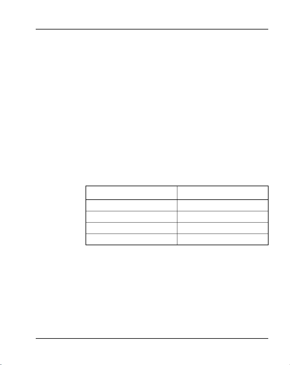
Finding the latest updates on the Nortel web site
The content of this documentation was current at the time the product
was released. To check for updates to the latest documentation and
software for CS 1000 Release 5.5, click one of the links below.
Latest Software Takes you directly to the Nortel
page for CS 1000 Release 5.5
software.
Latest Documentation Takes you directly to the Nortel
page for CS 1000 Release 5.5
documentation.
Communication Server 1000M and Meridian 1 Large System Installation and Commissioning
Page 22

Page 22 of 456 Finding the latest updates on the Nortel web site
NN43021-310 Standard 02.01 December 2007
Page 23
30
Page 23 of 456
System information
This document is a global document. Contact your system supplier or your
Nortel representative to verify that the hardware and software described are
supported in your area.
Subject
WAR NING
Before a Large System can be installed, a network
assessment must be performed and the network must be
VoIP-ready.
If the minimum VoIP network requirements are not met,
the system will not operate properly.
For information on the minimum VoIP network
requirements and converging a data network with VoIP,
refer to Converging the Data Network with VoIP
(NN43001-260).
This document provides installation and acceptance testing procedures for
Meridian 1 Large Systems and Communication Server 1000M Large
Systems.
Communication Server 1000M and Meridian 1 Large System Installation and Commissioning
Page 24

Page 24 of 456 System information
For this document, the CP PIV processor is assumed in the case of the
CS 1000M SG, Meridian 1 PBX 61C, CS 1000M MG, and Meridian 1
PBX 81C. If you are installing a system with a CP PII processor, please refer
to the CS 1000 Release 5.0 version of this document, available on the web at:
www.nortel.com/support
To access the NTP from the Technical Support page, go to the content listing
page for Communication Server 1000M:
1 Select the Browse product support tab on the main page.
2 Select Product Families from the drop-down menu, and then
Enterprise Communication Servers in the first window.
3 Select Communication Server 1000M Cabinet/Chassis from the
second window.
4 Select Documentation from the third window and click the Go button
on the right.
5 Use the filter provided under the Documentation tab to search for
Communication Server 1000M 4.0.
Note on legacy products and releases
This NTP contains information about systems, components, and features that
are compatible with Nortel Communication Server 1000 Release 5.5
software. For more information on legacy products and releases, click the
Technical Documentation link under Support & Training on the Nortel
home page:
www.nortel.com/
Applicable systems
This document applies to the following systems:
• Communication Server 1000M Half Group (CS 1000M HG)
• Communication Server 1000M Single Group (CS 1000M SG)
• Communication Server 1000M Multi Group (CS 1000M MG)
NN43021-310 Standard 02.01 December 2007
Page 25
System information Page 25 of 456
• Meridian 1 Option 51
• Meridian 1 PBX 51C
• Meridian 1 PBX 61C
• Meridian 1 Option 71
•Meridian1 PBX81
• Meridian 1 PBX 81C
Note: When upgrading software, memory upgrades may be required on
the Signaling Server, the Call Server, or both.
System migration
When particular Meridian 1 systems are upgraded to run CS 1000
Release 5.5 software and configured to include a Signaling Server, they
become CS 1000M systems. Table 1 lists each Meridian 1 system that
supports an upgrade path to a CS 1000M system.
Table 1
Meridian 1 systems to CS 1000M systems
This Meridian 1 system... Maps to this CS 1000M system
Meridian 1 PBX 51C CS 1000M Half Group
Meridian 1 PBX 61C CS 1000M Single Group
Meridian 1 PBX 81 CS 1000M Multi Group
Meridian 1 PBX 81C CS 1000M Multi Group
For more information, see Communication Server 1000M and Meridian 1
Large System Upgrade NTPs (NN43021-458 – NN43021-475).
Intended audience
This document is intended for individuals responsible for installing and
configuring Large Systems. To use this document, you should have a basic
knowledge of Large System equipment and operation. Contact Nortel for
information on installation courses. You should also read and fully
Communication Server 1000M and Meridian 1 Large System Installation and Commissioning
Page 26

Page 26 of 456 System information
understand the Communication Server 1000M and Meridian 1: Large System
Overview (NN43021-110) before you install a system.
Conventions
Terminology
The following systems are referred to generically as “Large System”:
• Communication Server 1000M Half Group (CS 1000M HG)
• Communication Server 1000M Single Group (CS 1000M SG)
• Communication Server 1000M Multi Group (CS 1000M MG)
• Meridian 1 Option 51
• Meridian 1 PBX 51C
• Meridian 1 PBX 61C
• Meridian 1 Option 71
•Meridian1 PBX81
• Meridian 1 PBX 81C
NTP feedback
Nortel strives to provide accurate documentation for our customers.
However, if you feel there are errors or omissions in this document, your
feedback is welcome.
Send comments via e-mail to gntsdoc@nortel.com or open a problem report
via the normal procedures.
Please provide as much information as possible including the NTP number,
standard version and date of the document, as well as the page, problem
description, and any supporting documentation and capture files.
NN43021-310 Standard 02.01 December 2007
Page 27

Related information
This section lists information sources that relate to this document.
NTPs
The following NTPs are referenced in this document:
• Circuit Card: Description and Installation (NN43001-311)
• Signaling Server: Installation and Commissioning (NN43001-312)
• System Security Management (NN43001-602)
• Software Input/Output: Administration (NN43001-611)
• Telephones and Consoles: Description, Installation, and Operation
(NN43001-567)
• Software Input/Output: System Messages (NN43001-712)
• Communication Server 1000M and Meridian 1: Large System Overview
(NN43021-110)
• Communication Server 1000M and Meridian 1: Large System Planning
and Engineering (NN43021-220)
• CS 1000M and Meridian 1 Large System Upgrades Overview
(NN43021-458)
System information Page 27 of 456
• CS 1000M and Meridian 1 51C to CS 1000M SG CP PIV Upgrade
(NN43021-459)
• CS 1000M and Meridian 1 Option 51C to CS 1000M MG (CP PIV FNF)
Upgrade (NN43021-460)
• CS 1000M and Meridian 1 61C to CS 1000M SG CP PIV Upgrade
(NN43021-461)
• CS 1000M and Meridian 1 61C CP PII to CS 1000M SG CP PIV
Upgrade (NN43021-462)
• CS 1000M and Meridian 1 61C to CS 1000M MG CP PIV FNF Upgrade
(NN43021-463)
• CS 1000M and Meridian 1 61C CP PII to CS 1000M MG CP PII FNF
Upgrade (NN43021-464)
Communication Server 1000M and Meridian 1 Large System Installation and Commissioning
Page 28

Page 28 of 456 System information
• CS 1000M and Meridian 1 61C CP PII to CS 1000M MG CP PIV FNF
Upgrade (NN43021-465)
• CS 1000M and Meridian 1 CS1000M SG CP PIV to CS 1000M MG CP
PIV FNF Upgrade (NN43021-466)
• CS 1000M and Meridian 1 71 to CS 1000M MG CP PIV FNF Upgrade
(NN43021-467)
• CS 1000M and Meridian 1 81 to CS 1000M MG CP PII FNF Upgrade
(NN43021-468)
• CS 1000M and Meridian 1 81C IGS to CS 1000M MG CP PII FNF
Upgrade (NN43021-469)
• CS 1000M and Meridian 1 81C FNF to CS 1000M MG CP PII FNF
Upgrade (NN43021-470)
• CS 1000M and Meridian 1 81C IGS to CS 1000M MG CP PIV FNF
Upgrade (NN43021-471)
• CS 1000M and Meridian 1 CS 1000M MG CP PII IGS to CS 1000M MG
CP PII FNF Upgrade (NN43021-472)
• CS 1000M and Meridian 1 CS 1000M MG CP PII IGS to CS 1000M MG
CP PIV FNF Upgrade (NN43021-473)
• CS 1000M and Meridian 1 CS 1000M MG CP PII FNF to CS 1000M MG
CP PIV FNF Upgrade (NN43021-474)
Other documentation
The following documentation is referenced in this document:
• Candeo Power System User Guide (P0914425)
• Candeo Power System Installation Guide (P0914426)
• Candeo SP 48300 Power System AP6C55AA User Manual (P7000154)
• Candeo SP 48300 Power System AP6C55AA Installation Manual
(P7000289)
NN43021-310 Standard 02.01 December 2007
Page 29

System information Page 29 of 456
Online
To access Nortel documentation online, click the Technical Documentation
link under Support & Training on the Nortel home page:
www.nortel.com
CD-ROM
To obtain Nortel documentation on CD-ROM, contact your Nortel customer
representative.
Communication Server 1000M and Meridian 1 Large System Installation and Commissioning
Page 30

Page 30 of 456 System information
NN43021-310 Standard 02.01 December 2007
Page 31

36
Page 31 of 456
Introduction
Contents
This section contains information on the following topics:
Overview . . . . . . . . . . . . . . . . . . . . . . . . . . . . . . . . . . . . . . . . . . . . . . . . 31
Summary of procedures . . . . . . . . . . . . . . . . . . . . . . . . . . . . . . . . . . . . 33
Overview
WAR NING
Before a Large System can be installed, a network
assessment must be performed and the network must be
VoIP-ready.
If the minimum VoIP network requirements are not met,
the system will not operate properly.
For information on the minimum VoIP network
requirements and converging a data network with VoIP,
refer to Converging the Data Network with VoIP
(NN43001-260).
This document describes the procedures used to install and configure a
Large System. For proper installation, perform the steps in the sequence
stated in “Summary of procedures.” The summary will refer you to other
sections within this document. After completing the steps listed in those
sections, return to the summary and continue on to the next step.
Communication Server 1000M and Meridian 1 Large System Installation and Commissioning
Page 32

Page 32 of 456 Introduction
Whenever possible, install external power equipment before the system
installation. If reserve power equipment is used, install it according to the
manufacturer’s instructions.
To install telephones and attendant consoles, see Telephones and Consoles:
Description, Installation, and Operation (NN43001-567).
System installation must be performed by qualified personnel only.
NN43021-310 Standard 02.01 December 2007
Page 33

Summary of procedures
1 Prepare equipment for installation; go to “Preparing the equipment for
installation” on page 62.
2 Place the fourth module on a column (if required); go to “Placing the
fourth module on a column” on page 65.
3 Position and level equipment; go to “Positioning and leveling
equipment” on page 71.
Note: If earthquake bracing is required, go to “Installing earthquake
bracing” on page 343. The section will provide procedures for installing
column and floor bracing and positioning and levelling equipment.
When those procedures are complete, return to Step 4 or Step 5 (as
applicable) in this summary.
4 Install overhead cable tray kits (if required); go to “Installing overhead
cable tray kits” on page 89.
5 Install power supplies in all modules:
a Make sure the system is disconnected from any power source.
b Set switches and breakers on all module power supplies or module
power distribution units (MPDU) to OFF.
Introduction Page 33 of 456
c Insert each power supply into the appropriate card cage and hook the
locking devices.
6 Install a NT4N39AA CP PIV Processor Pack and blank faceplate
(N0026096) to cover MMDU slot
7 Install power equipment and ground wiring:
— For AC-powered systems, go to “Installing AC power” on page 77.
— For DC-powered systems, go to “Installing DC power” on page 93.
8 Plan and designate the main distribution frame (MDF); go to “Planning
and designating a Main Distribution Frame” on page 133.
9 Install Power Failure Transfer Units (PFTU) (if required); go to
“Installing Power Failure Transfer Units” on page 145.
10 Configure the system monitor; go to “Configuring the system monitor”
on page 151.
Communication Server 1000M and Meridian 1 Large System Installation and Commissioning
Page 34

Page 34 of 456 Introduction
11 Connect a system terminal (or modem); go to “Connecting a system
terminal or modem” on page 171.
12 Install cabling:
— To cable Common Equipment, go to “Cabling Common Equipment
— To cable network loops, go to “Cabling network modules and loops”
— To cable IPE Modules to the MDF and to connect lines and trunks,
13 Power up the system and load the system software; go to “Powering up
the system and initial loading” on page 299.
Note: If you are upgrading your system, do not install new software.
Instead, return to the upgrade procedures provided in Communication
Server 1000M and Meridian 1 Large System Upgrade NTPs
(NN43021-458 – NN43021-475).
14 Perform acceptance tests; go to “Performing acceptance tests” on
page 335.
15 To test circuit cards, see “Acceptance tests” in Circuit Card: Description
and Installation (NN43001-311). To test telephones and attendant
consoles, see Telephones and Consoles: Description, Installation, and
Operation (NN43001-567).
in a Single Group system” on page 187.
on page 239.
go to “Cabling lines and trunks” on page 261.
16 Replace all covers and grills on the front and rear of the system.
NN43021-310 Standard 02.01 December 2007
Page 35

Introduction Page 35 of 456
Table 2
List of tasks in subsections
Task Go to page
Preparing for installation 37
Placing the fourth module on a column 65
Positioning and leveling equipment 71
Installing overhead cable tray kits 89
Installing AC power 77
Installing DC power 93
Planning and designating a Main Distribution Frame 133
Installing Power Failure Transfer Units 145
Configuring the system monitor 151
Connecting a system terminal or modem 171
Cabling Common Equipment in a Single
Group system
Cabling Common Equipment in a Multi Group system 207
Cabling network modules and loops 239
Cabling lines and trunks 261
Powering up the system and initial loading 299
Performing acceptance tests 335
Installing earthquake bracing 343
Adding a module to a column 363
Communication Server 1000M and Meridian 1 Large System Installation and Commissioning
187
Page 36

Page 36 of 456 Introduction
NN43021-310 Standard 02.01 December 2007
Page 37

64
Page 37 of 456
Preparing for installation
Contents
This section contains information on the following topics:
Requirements. . . . . . . . . . . . . . . . . . . . . . . . . . . . . . . . . . . . . . . . . . . . . 37
System equipment – UEMs. . . . . . . . . . . . . . . . . . . . . . . . . . . . . . . . . . 38
System options . . . . . . . . . . . . . . . . . . . . . . . . . . . . . . . . . . . . . . . . . . . 45
Cable routing guidelines . . . . . . . . . . . . . . . . . . . . . . . . . . . . . . . . . . . . 54
Equipment handling precautions. . . . . . . . . . . . . . . . . . . . . . . . . . . . . . 58
Preparing the equipment for installation . . . . . . . . . . . . . . . . . . . . . . . . 62
Requirements
WAR NING
Before a Large System can be installed, a network
assessment must be performed and the network must be
VoIP-ready.
If the minimum VoIP network requirements are not met,
the system will not operate properly.
For information on the minimum VoIP network
requirements and converging a data network with VoIP,
refer to Converging the Data Network with VoIP
(NN43001-260).
Communication Server 1000M and Meridian 1 Large System Installation and Commissioning
Page 38

Page 38 of 456 Preparing for installation
Before system equipment is delivered to the installation site, you must
consider these requirements:
• Fire protection and safety requirements
• Equipment room requirements
• Grounding and power requirements
• Cable requirements
Specifications for these requirements and for developing the equipment room
floor plan are provided in Communication Server 1000M and Meridian 1:
Large System Planning and Engineering (NN43021-220).
System equipment – UEMs
Universal Equipment Modules (UEM) are the building blocks of the
communication system. UEMs are generic metal frames equipped with
covers. Each UEM is a self-contained unit with power, a card cage, I/O
panels, and cable routing channels. Each UEM houses sets of equipment used
in system operations (see Figure 1 on page 39).
UEMs are stacked in columns
UEMs are stacked in columns, up to four modules high. Within a column, the
levels are referred to as tiers. The UEMs are numbered 0 to 3 from the bottom
up (see Figure 1 on page 39). Cables connect cards in the same module,
between two modules, and between cards and the I/O panel in the same
module.
Column components
Each column contains a pedestal base, a top cap, and up to four modules.
Pedestals
Each column sits on a pedestal. The pedestal contains power, cooling, and
system monitoring equipment.
• A Power Distribution Unit (PDU) in the back of the pedestal supplies
either AC or DC power to the column.
NN43021-310 Standard 02.01 December 2007
Page 39

Preparing for installation Page 39 of 456
• A System Monitor checks the column’s cooling and power systems.
• A blower unit (accessible from the front of the pedestal) forces air up
through the modules to cool the circuit cards.
Figure 1
Universal Equipment Modules
N
O
R
T
E
Module 3
Module 2
Module 1
Module 0
L
Universal
Equipment Module
N
O
R
T
E
L
Universal
Equipment Module
N
O
R
T
E
L
Universal
Equipment Module
N
O
R
T
E
L
Universal
Equipment Module
Tier 0
Top Cap
N
O
R
T
E
L
Equipment Module
Universal
Module 0
Pedestal
4-tier column
1-tier column
553-AAA1241
Top caps
A top cap is mounted on the top module of each column. It contains:
• Air exhaust grills in the cap that release air from the blowers in the
pedestal.
• A heat sensor that monitors the temperature of the column.
Communication Server 1000M and Meridian 1 Large System Installation and Commissioning
Page 40

Page 40 of 456 Preparing for installation
• A red LED in the front of the cap’s exhaust grill that lights if the system
overheats or if a power outage occurs.
• Ladder racks for routing cables can also be fitted to the top caps.
Modules
Up to four modules can be included in a column. The modules can include:
• NT4N41 CompactPCI
Large Systems
• NT8D35 Network Module – required for Meridian 1 PBX 81C and
CS 1000M MG
• NT8D37 Intelligent Peripheral Equipment (IPE) Module – required for
all Large Systems
In addition, modules that house application-specific equipment can be
included in a column.
Columns are grouped in rows
A system can have one column, or multiple columns attached in rows.
Column 0 is always the column containing the “Core/Net 0” module.
Column 1 is placed to the left of Column 0 and must contain the “Core/Net 1”
module.
®
(cCPI) Core/Network Module – required for all
Column 0 and Column 1 are placed at the far left of the row (front view).
Column numbering then continues to the right of Core 0 (see Figure 2 on
page 41).
Additional rows are configured with the lowest numbered column on the far
left and the highest numbered column on the far right (front view).
For compliance with electromagnetic interference/radio frequency
interference (EMI/RFI) standards, spacer kits are provided to interconnect the
columns in a multiple-column system.
NN43021-310 Standard 02.01 December 2007
Page 41

Preparing for installation Page 41 of 456
Figure 2
Example of Large System column row
UEMs are identified by function
Each UEM contains a specialized set of equipment to digitalize, process, and
route phone calls and voice messages (see Figure 3 on page 42).
Communication Server 1000M and Meridian 1 Large System Installation and Commissioning
Page 42

Page 42 of 456 Preparing for installation
Figure 3
UEMs identified by function
Card cage
Inside each UEM is a metal card cage. This card cage holds the circuit cards,
power card, and related equipment for that module. UEMs are named for the
function of that card cage.
Card cages are bolted inside the UEM case. Card cages can be removed and
replaced for repairs or upgrades.
NN43021-310 Standard 02.01 December 2007
Page 43

Core/Net module
Large Systems feature the NT4N41 Core/Net module. The Core/Net module
provides a unified hardware platform for single group and multi-group
configurations. The Core/Net module supports:
• An integrated cPCI shelf.
• A NT4N48 System Utility card that incorporates the functionality of the
System Utility Transition card, LCD display, and the security device
holder.
• A fanout panel (see Figure 4 on page 44) to provide connectivity to the
network shelf.
• Upgrades from single group to multi-group configurations (requiring a
new keycode file and any additional hardware necessary for a
multi-group system).
Preparing for installation Page 43 of 456
Communication Server 1000M and Meridian 1 Large System Installation and Commissioning
Page 44
Page 44 of 456 Preparing for installation
Figure 4
NT4N41 Core/Net shelf fanout panel (backplane)
j4
slot 12
port 1
Group 6
j3
slot 12
port 0
j4
slot 12
port 0
Group 7
j3
slot 12
port 1
NN43021-310 Standard 02.01 December 2007
Group 3Group 4Group 5
j3
slot 11
port 1
j4
slot 11
port 1
j3
slot 11
port 0
j4
slot 11
port 0
j3
slot 10
port 1
j4
slot 10
port 1
j3
slot 10
port 0
j4
slot 10
port 0
j3 slot 9 port 0 j4 slot 9 port 0
Group 0
Group 1Group 2
j3
slot 9
port 1
j4
slot 9
port 1
Page 45

System options
The procedures in this document apply to the following system options:
• Meridian 1 PBX 61C: dual CPU, full network group
• Meridian 1 PBX 81C: dual CPU, multiple network groups
• CS 1000M SG: a Meridian 1 PBX 61C system upgraded to include a
• CS 1000M MG: a Meridian 1 PBX 81C system upgraded to include a
All system options are available in both AC- and DC-powered versions.
System architecture and module types are described in Communication
Server 1000M and Meridian 1: Large System Overview (NN43021-110).
The components of AC-powered systems, DC-powered systems, and reserve
power options for both are described in this document.
Preparing for installation Page 45 of 456
Signaling Server (see note below)
Signaling Server (see note below)
Note: For information about Signaling Server installation and
configuration, see Signaling Server: Installation and Commissioning
(NN43001-312).
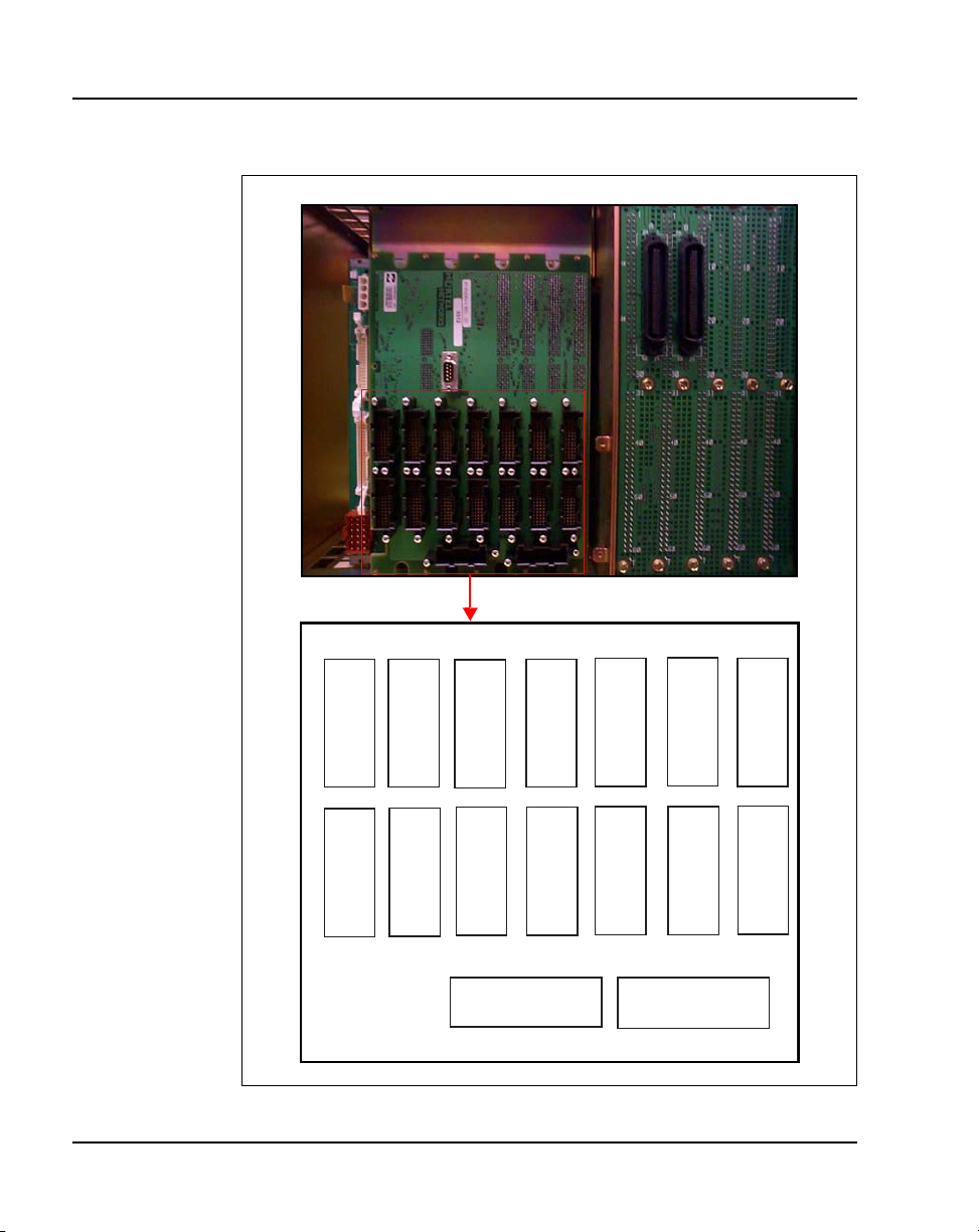
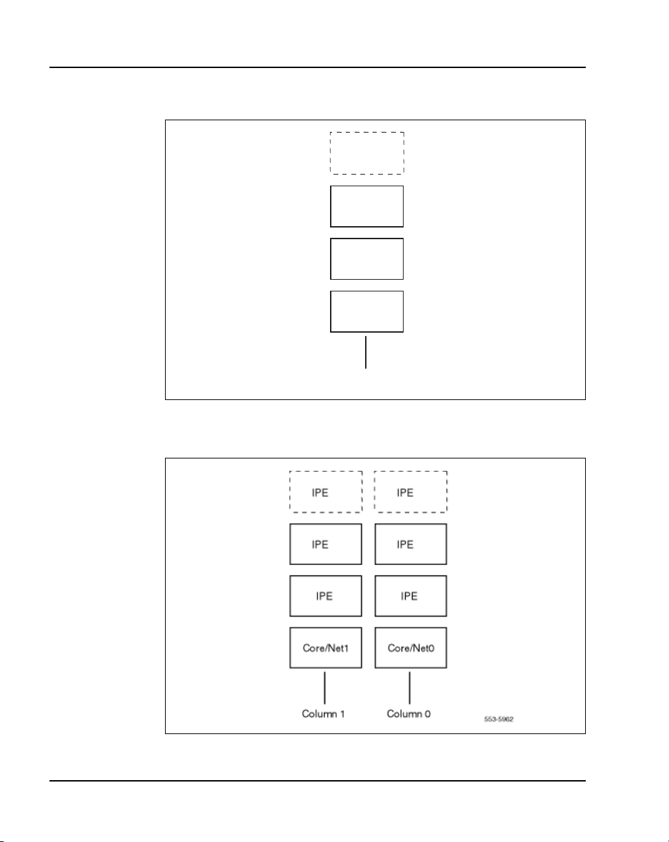
Meridian 1 PBX 61C and CS 1000M SG
These systems feature a dual Pentium Processor with standby processing
capability, fully redundant memory, and a full network group. Two Core/Net
modules and one IPE module are the minimum installation requirements.
Additional IPE modules and application modules can be used. The modules
are stacked (see Figure 5 on page 46) or installed side-by-side (see Figure 6
on page 46).
Communication Server 1000M and Meridian 1 Large System Installation and Commissioning
Page 46
Page 46 of 456 Preparing for installation
Figure 5
Meridian 1 PBX 61C stacked configuration
IPE
IPE
Core/Net 1
Core/Net 0
Main column
Figure 6
Meridian 1 PBX 61C side-by-side configuration
553-5960
NN43021-310 Standard 02.01 December 2007
Page 47

Preparing for installation Page 47 of 456
Meridian 1 PBX 81C and CS 1000M MG
These systems feature a dual Pentium Processor with standby processing
capability, two Core/Net modules installed side-by-side, and two or more
network groups. The Core/Net modules provide the first network group, and
network module pairs provide additional network groups.
These systems support up to eight network groups, as shown in Figure 3 on
page 42. Fiber Network Fabric provides complete non-blocking
communication between the network groups, eliminating busy signals for
network-blocked calls between groups.
Figure 7 on page 47 shows a multi-group system with four network modules.
If the ceiling height is too low for the four-tier column, a three-tier column
can be used, as shown in Figure 8 on page 48.
Figure 7
Four-tier multi-group system
IPE
NET
NET
Core 1 Core 0
IPE
NET
NET
UEM
IPE
IPE
553-AAA1242
Communication Server 1000M and Meridian 1 Large System Installation and Commissioning
Page 48

Page 48 of 456 Preparing for installation
Figure 8
Three-tier multi-group system
NET
NET
NET
NET
Core 1 Core 0
CP PIV
A Call Processor Pentium IV (CP PIV) Large System processor was
introduced for CS 1000 Release 4.5. It features the following enhancements:
• a PCI-based design that is compatible with current CP PII architecture
• an Intel Pentium M processor
• two Compact Flash (CF) sockets (one on-board and one hot-swappable
on the faceplate). The on-board CF is referred to as the Fixed Media Disk
(FMD), and the faceplate CF is referred to as the Removable Media Disk
(RMD). See Figure 9 on page 50 and Figure 10 on page 51.
IPE
IPE
IPE
UEM
IPE
IPE
553-AAA1243
• 512 MBytes of DRAM memory
NN43021-310 Standard 02.01 December 2007
Page 49

Preparing for installation Page 49 of 456
New system types
There are two new system types for CP PIV:
• 3521 (Meridian 1 Option 61C and CS 1000M SG)
• 3621 (Meridian 1 Option 81C and CS 1000M MG, CS 1000E)
New hardware
CP PIV features the following new hardware:
• A CP PIV processor board. See Figure 9 on page 50 (side view) and
Figure 10 on page 51 (front view).
• A blank panel that replaces the NT4N43 MMDU. The blank panel is
designed to fill the gap and ensure proper air flow direction.
Note: The front panel USB port on the CP PIV card is reserved for
future applications.
Communication Server 1000M and Meridian 1 Large System Installation and Commissioning
Page 50

Page 50 of 456 Preparing for installation
Figure 9
CP PIV call processor card (side)
Fixed
Media
Drive (FMD)
Removable Media Drive (RMD)
512 MBytes DDR memory
Rear
CPU
Front
NN43021-310 Standard 02.01 December 2007
Page 51

Figure 10
CP PIV call processor card (front)
Removable Media Drive (RMD)
Preparing for installation Page 51 of 456
Lan 1
USB Port
COM 1
INIT
Communication Server 1000M and Meridian 1 Large System Installation and Commissioning
Lan 2
COM 2
RESET
Page 52

Page 52 of 456 Preparing for installation
Signaling Server
CS 1000M systems use a Signaling Server. The Signaling Server provides a
central processor to drive the signaling for IP Phones and IP Peer
Networking. The Signaling Server is an industry-standard PC-based server
that provides signaling interfaces to the IP network, using software
components that operate on the VxWorks™ real-time operating system.
The Signaling Server can be installed in a load-sharing redundant
configuration for higher scalability and reliability. The following software
components can operate on the Signaling Server.
• Terminal Proxy Server (TPS)
• SIP/H.323 Gateway Signaling software
• Network Routing Service (NRS) (optionally redundant)
• Element Manager web server
• Application Server for Personal Directory, Redial List, and Callers List
for UNIStim IP Phones
Signaling Server is an application server which houses any combination of
Gatekeeper, H.323 Gateway, Line Terminal Proxy Server and Element
Manager. The Signaling Server is mounted on a 480 mm (19 in.) rack (see
Figure 11).
NN43021-310 Standard 02.01 December 2007
Page 53

Figure 11
CS 1000M Large System
Engineering rules
Each system is defined using the following assumptions and general
engineering rules.
1 A system may be upgraded to the next larger system type as defined in
Preparing for installation Page 53 of 456
Business Policy
Switch
Signaling
Server
553-AAA0561
Communication Server 1000M and Meridian 1 Large System Upgrade
NTPs (NN43021-458 – NN43021-475).
2 When expanding to the next system type, the changes to the physical
configuration should be kept as simple as possible to reduce downtime
and installation costs.
3 A module column should be built up to the maximum of four modules
before moving to the next new column. In installations where the ceiling
does not allow four-high columns, the alternate configuration of
three-high tiers can be used.
4 Vertical routing of the internal signal cables should be done only on the
right side of a module.
5 The CPU modules must be on the bottom of a column or one level up for
proper cooling and reliability.
Communication Server 1000M and Meridian 1 Large System Installation and Commissioning
Page 54

Page 54 of 456 Preparing for installation
6 Sending and receiving cables must be of equal lengths and as short as
possible.
7 In order to optimize network FIJI cabling, mount the NTD35 network
modules in pairs in the same column, one module on top of the other in
the middle tiers. The modules must be stacked in one contiguous
equipment bay. The longest FIJI cable (NTRC48FA) is 8 m (26 ft),
which is the maximum distance of the furthest network module from the
Core/Net modules.
8 The IPE modules can be located separately from the CPU and network
bay, by up to the maximum network cable length of 13.5 m (45 ft).
9 Core/network modules can also be on top of each other in the first and
second tier in multi-group systems.
Cable routing guidelines
A system layout, preconfigured at the factory, is included in the software box
with each system shipment. Before you route cables, refer to the “to-from”
cable connections in the system layout. Note that there are a variety of cable
lengths. Make sure you install the designated cable for each connection.
Because the cable troughs (see Figure 12 on page 55) and spaces on the sides
of each module are within the EMI shielding of the system, unshielded cables
can be routed in those areas. The corner vertical channels in the rear of the
module are outside of the EMI shield. Cables routed in the vertical channels
must be shielded, and must enter and exit the EMI-shielded area through I/O
panels and adapters.
NN43021-310 Standard 02.01 December 2007
Page 55

Preparing for installation Page 55 of 456
Figure 12
Cable routing troughs – front view of module
Cabling troughs
553-3117
A typical routing scenario from the faceplate of a printed circuit pack (PCP)
to one of the I/O panels is as follows:
• The cable comes off the faceplate of a PCP and drops down into the front
horizontal cable trough.
• The cable is routed to the right side of the module in the horizontal cable
trough to the vertical cable trough.
• The cable is routed to the back of the module and into the rear horizontal
cable trough.
• The cable is routed to the left or right I/O panel at the rear of the module.
When connecting two half-group networks together, the cables are routed
vertically through the square holes in the rear horizontal cable trough.
All other internal vertical cable routing from one module to another should be
done only in the right vertical cable trough.
Communication Server 1000M and Meridian 1 Large System Installation and Commissioning
Page 56

Page 56 of 456 Preparing for installation
6
Since all faceplate to I/O panel cables are the same length and card positions
in the card cage vary, a cable can contain excess slack. It is therefore
recommended that cables from cards in the left side of the card cage use the
right I/O panel and cables from cards in the right side of the card cage use the
left I/O panel whenever possible, as shown in Figure 13.
Figure 13
Top view of front to I/O connector panel routing
Right I/O Connector Panel
I/O Panel
PS
This side uses right I/O Connector PanelThis side uses left I/O Connector Panel
Left I/O Connector Panel
Card Cage
553-749
As space permits, cables can be routed:
1 Horizontally in the cable troughs at the front, rear, and sides of the
module
Note: In a DC-powered module, because there is no MPDU, there is
room to route cables horizontally from front to rear on the left side (front
view) of the module.
NN43021-310 Standard 02.01 December 2007
Page 57

Preparing for installation Page 57 of 456
7
2 Vertically on the sides of the module
3 Vertically in the corner channels in the rear of the module (shielded
cables only)
CAUTION
Damage to Equipment
Cables must be routed as perpendicular as possible
to any nearby power cables. Avoid routing cables
near power cables if alternate routing is available. (At
the rear of the module, cables routed between the I/O
panel and the rear cover can be parallel to the power
cables because the panel provides EMI shielding.)
Nortel recommends that you use the 90° connector end of the cable to route
the cable through a module or cabinet instead of the 180° end, since some
openings are small (see Figures 14 and 15). Furthermore, Nortel recommends
that you route cables top-to-bottom so gravity will ease installation.
Figure 14
90° cable connector
553-749
Communication Server 1000M and Meridian 1 Large System Installation and Commissioning
Page 58

Page 58 of 456 Preparing for installation
8
Figure 15
180° cable connector
Equipment handling precautions
To avoid personal injury and equipment damage, review the following
guidelines before handling the equipment.
553-749
Unloading equipment
Special ramps, packed inside the pallet holding Column 0, must be used to
move the equipment off the pallet. Follow the instructions provided with the
ramps.
CAUTION
Damage to Equipment
Never pry up the pedestal to lift the column. This
could damage to the pedestal. Manually slide the
column down the ramps provided.
NN43021-310 Standard 02.01 December 2007
Page 59

Working with power supplies
There are no user-repairable components in the power supply. If a power
supply fails, the complete unit must be replaced. Do not disassemble a power
supply under any circumstances.
DANGER OF ELECTRIC SHOCK
To avoid the danger of electric shock, be careful
when working with power equipment and
connections.
Comply with all Warnings.
External power supplies such as a UPS, power plant, or batteries, may be
heavy and require special handling procedures and additional personnel for
unloading and installation. Also, be aware of weight distribution and keep the
equipment room floor from being overly stressed.
Handling circuit cards
Follow these precautions when handling circuit cards.
1 Unpack or handle cards away from electric motors, transformers, or
similar machinery.
Preparing for installation Page 59 of 456
2 Handle cards by the edges only. Do not touch the contacts or
components.
3 Set cards on a protective antistatic bag. If an antistatic bag is not
available, hand-hold the card, or set it in a card cage unseated from the
connectors.
4 Store cards in protective packing.
5 Do not stack cards on top of each other unless they are packaged.
6 Wear a properly connected antistatic wrist strap when you work on the
equipment. If a wrist strap is not available, regularly touch one of the
bare metal strips in the module to discharge static. Figure 16 on page 60
shows the wrist strap connection points and the location of the bare metal
strips you should touch.
Communication Server 1000M and Meridian 1 Large System Installation and Commissioning
Page 60

Page 60 of 456 Preparing for installation
Figure 16
Static discharge points
Wrist strap
connection point
Power supply slot
Module
rear
Bare metal strip
Wrist strap
connection point
Module
front
Bare metal strip
553-5000
NN43021-310 Standard 02.01 December 2007
Page 61
Preparing for installation Page 61 of 456
DenAn regulatory notice for Japan
Communication Server 1000M and Meridian 1 Large System Installation and Commissioning
Page 62

Page 62 of 456 Preparing for installation
Preparing the equipment for installation
Use the equipment room floor plan to position equipment. See
Communication Server 1000M and Meridian 1: Large System Planning and
Engineering (NN43021-220) to prepare the equipment room and floor plan.
WAR NING
A fully loaded column weighs 275 kg (606 lb). More
than one person is required to remove equipment
from shipping pallets.
WAR NING
Module covers are not hinged; do not let go of the
cover. Lift the cover away from the module and set it
out of the work area.
Procedure 1
Preparing the equipment for installation
1 Remove equipment from the shipping pallets; follow the unpacking
instructions that come with the packaging material.
2 Remove the front and rear covers from each module:
NN43021-310 Standard 02.01 December 2007
Page 63

Preparing for installation Page 63 of 456
a. With a flat blade screwdriver, turn the lock clockwise on the two
locking latches (see Figure 17 on page 63).
Figure 17
Locking latches on the module cover
unlatch cover
Turn lock screw
up to lock
Slide to
553-A0132
b. Simultaneously push the latches toward the center of the cover and
pull the cover toward you while lifting it away from the module.
c. Set the covers aside until the installation is complete.
3 Remove the front and rear grills from each pedestal:
a. Loosen the two captive screws that secure the grill.
b. Pull the grill forward and lift it out of the base of the pedestal (see
Figure 18 on page 64).
c. Set the grills aside until the installation is complete.
Communication Server 1000M and Meridian 1 Large System Installation and Commissioning
Page 64

Page 64 of 456 Preparing for installation
Figure 18
Removing the pedestal grill
4 Make sure all of the items on the system order form are on the packing
slip that comes with the equipment.
Captive screw
Captive screw
553-3054
5 Inspect all equipment for physical damage. Report any damage to your
supplier.
6 Check the option settings on all cards that have a switch symbol on the
faceplate.
For a list of all option switch and jumper settings, refer to Circuit Card:
Description and Installation (NN43001-311).
NN43021-310 Standard 02.01 December 2007
End of Procedure
Page 65

70
Page 65 of 456
Placing the fourth module on a column
Contents
This section contains information on the following topics:
Overview . . . . . . . . . . . . . . . . . . . . . . . . . . . . . . . . . . . . . . . . . . . . . . . . 65
Placing the fourth module on a column . . . . . . . . . . . . . . . . . . . . . . . . 65
Overview
A four-module column is shipped in two segments. One shipping pallet
carries the pedestal and three modules. Another shipping pallet carries the
fourth module and top cap.
Starting at the bottom of the column, modules are numbered from zero to
three in each column.
Placing the fourth module on a column
Use Procedure 2 to place the fourth module and top cap on the column. To
add a module to a column that is already powered, see the procedures in
“Adding a module to a column” on page 363.
CAUTION
System Failure
Never add a Common Equipment module in the third
or the fourth tier of a column.
Communication Server 1000M and Meridian 1 Large System Installation and Commissioning
Page 66

Page 66 of 456 Placing the fourth module on a column
WAR NING
A fully loaded module weighs approximately 60 kg
(130 lb). More than one person is required to place a
module on a column.
Procedure 2
Placing the fourth module on a column
1 Position and secure the fourth module.
a. Locate the positioning guides on the third module (see Figure 19).
b. Position the fourth module so it faces the same direction as the
column.
c. Remove the front and rear module covers on the fourth module and
rear module cover on the third module.
d. Place the fourth module on top of the column and adjust it until it is
seated securely on the positioning guides.
e. Remove the I/O safety panel in the fourth module to gain access for
installing the center mounting bolt.
f. Use a 14 mm (9/16 in.) socket wrench to secure the fourth module
with five mounting bolts (see Figure 20 on page 68).
NN43021-310 Standard 02.01 December 2007
Page 67

Placing the fourth module on a column Page 67 of 456
Figure 19
Module positioning guides
Rear
Positioning guides
Front
Opening for
cables
553-3056
Communication Server 1000M and Meridian 1 Large System Installation and Commissioning
Page 68

Page 68 of 456 Placing the fourth module on a column
Figure 20
Module mounting bolts
Mounting
bolts
553-3057
2 Connect the module-to-module power and system monitor cables.
a. Connect the power connectors between the modules (see Figure 21
on page 69).
b. Connect the system monitor cable from connector J2 on the third
module to J1 on the fourth module.
NN43021-310 Standard 02.01 December 2007
Page 69

Placing the fourth module on a column Page 69 of 456
Figure 21
Power and system monitor connections
Top cap
I/O safety
panel
Module 3
I/O safety
panel
Module 2
(Modules 0 and 1 below)
Rear of the column
3 Reinstall the I/O safety panel in each module.
4 Replace the module covers.
End of Procedure
Power connectors
between modules
System monitor
connector —
J2 in Module 2 to
J1 in Module 3
553-5068
Communication Server 1000M and Meridian 1 Large System Installation and Commissioning
Page 70

Page 70 of 456 Placing the fourth module on a column
NN43021-310 Standard 02.01 December 2007
Page 71

76
Page 71 of 456
Positioning and leveling equipment
Contents
This section contains information on the following topic:
Positioning and leveling the equipment . . . . . . . . . . . . . . . . . . . . . . . . 71
Positioning and leveling the equipment
Columns normally stand on adjustable feet that provide leveling capability
and ground isolation. However, casters are available and can be used for
two-tier columns. If a third module is added to a column with casters, the
casters must be replaced with leveling feet.
Note: If earthquake bracing is required, go to “Installing earthquake
bracing” on page 343 to install column and floor bracing, and to position
and level equipment. When those procedures are complete, return to
Step 4 or Step 5 (as applicable) in the initial installation procedure.
Use Procedure 3 to position and level the equipment.
Procedure 3
Positioning and leveling the equipment
1 Check the equipment room floor plan to position columns.
2 Level the column.
a. Remove the front and rear exhaust grills.
b. Remove the front and rear air intake grills.
Communication Server 1000M and Meridian 1 Large System Installation and Commissioning
Page 72

Page 72 of 456 Positioning and leveling equipment
c. Position a level across the top module cover on the front of the
column.
d. Loosen the locking nuts on the feet.
e. Adjust the feet on each pedestal up or down to level the column.
f. Perform step a to step e for leveling the rear of the system.
g. Tighten the locking nuts.
Note: Leave at least 12.5 mm (1/2 in.) between the floor and the bottom
of the pedestal for air flow required by the blower unit.
3 For a multiple-column system, install NT8D49 Spacer Kits between
columns.
a. Remove the front and rear module covers.
b. Remove the front and rear intake grills, if not already removed.
c. Remove the trim plates from the module side where the spacer will
be attached by removing the four screws securing the trim plates to
the module.
d. Remove the side panel from the module’s side where the spacer is
being attached by removing the four screws securing the side panel
to the module.
e. Attach gaskets to both sides in the front section of each spacer (see
Figure 22).
NN43021-310 Standard 02.01 December 2007
Page 73

Positioning and leveling equipment Page 73 of 456
Figure 22
Positioning spacer gaskets
Gasket placement
553-5641
f. Attach a spacer to one side of each module, except the end column
(see Figures 23 and 24).
— Position a spacer against the module.
— Insert one standoff between the spacer and module.
— Insert the one screw and tighten.
FrontRear
— Repeat the process for the remaining standoff and screws.
CAUTION
Damage to Equipment
Do not try to adjust the horizontal position of a
column by tightening the spacer screws. Tightening
the screws with the columns too far apart will warp
the spacer.
g. One at a time, push columns together, level, align, and attach the
other side of the spacers.
Communication Server 1000M and Meridian 1 Large System Installation and Commissioning
Page 74

Page 74 of 456 Positioning and leveling equipment
Figure 23
Spacer positioning
Rear
Spacer
Screw Stand-off
NN43021-310 Standard 02.01 December 2007
Spacer
553-A0130
Page 75

Positioning and leveling equipment Page 75 of 456
Figure 24
Column positioning with spacers
Step 1
Step 2
Attach spacers to one side of each column
(except the end column)
(end column)
Spacers
One at a time, push columns together, level, align,
and attach the other side of the spacer
Positioning completedStep 3
Spacers
553-5067
End of Procedure
Communication Server 1000M and Meridian 1 Large System Installation and Commissioning
Page 76

Page 76 of 456 Positioning and leveling equipment
NN43021-310 Standard 02.01 December 2007
Page 77

88
Page 77 of 456
Installing AC power
Contents
This section contains information on the following topics:
AC-powered systems. . . . . . . . . . . . . . . . . . . . . . . . . . . . . . . . . . . . . . . 77
Safety ground/protective earth and logic return wiring . . . . . . . . . . . . 78
Installing safety ground/protective earth and logic return wiring . . . . . 82
Installing UPS ground cabling . . . . . . . . . . . . . . . . . . . . . . . . . . . . . . . 85
AC-powered systems
For AC-powered systems, use Procedure 4 on page 82 to install safety
ground/protective earth and logic return wiring, and to install ground and
alarm cabling for a UPS.
For AC-powered systems without reserve power, one input receptacle is
required per column, within 2.4 m (8 ft) of each pedestal. One IG-L6-30 or
L6-30 receptacle is required for each column. Instead of using the power plug
provided, the Power Distribution Unit (PDU) can be hard-wired to the power
source. In this case, #10 AWG conductors routed through 20 mm (3/4 in.)
conduit are generally used. The leads connect to the L1, L2, and GND
terminations on the field wiring terminal block on the PDU.
Note: Do not use ground fault circuit interrupt (GFCI) devices on
Large System AC power feeds.
Communication Server 1000M and Meridian 1 Large System Installation and Commissioning
Page 78

Page 78 of 456 Installing AC power
Systems that use reserve power plug into the UPS, which in turn plugs into
the power source (associated batteries can be located within the UPS or
installed externally). Consult the UPS documentation for receptacle
requirements.
As a safety precaution, all AC service panels should be located in an area that
is easily accessible at all times to allow for emergency shutdown. An optimal
location would be near, or just outside the entry to the room containing the
Large System (or the UPS, if equipped). Each circuit breaker in the panels
should be clearly marked to identify the system component or components it
services.
Safety ground/protective earth and logic return wiring
A separate safety ground/protective earth connection is required. The safety
ground/protective earth wire must be #6 AWG or larger. It must connect the
pedestal to the single-point ground (SPG). Using an isolated ground (IG) bus
as the single-point ground is recommended. To fulfill this function, Nortel
offers the NT6D5304 Logic Return Equalizer (LRE), equipped with nine
terminations. A large ground bar (NT6D5303), equipped with 48
terminations, is also available.
An AC equipment ground (ACEG) bus in the service panel or transformer is
acceptable but not recommended. If used, the ACEG bus conductor must be
a low impedance path to an approved source for ground. It must not contain
induced electrical noise from sources such as building metallic structures
(building steel, metallic conduit, metal pipes, etc.). Figures 25, 26, and 27
beginning on page 79 show an ACEG as the single-point ground.
Depending on the distances between columns, the location of the service
panel, and the availability of panel SPG connection points, safety ground/
protective earth wiring can be daisy-chained or run independently from each
column to the service panel. Figures 26 and Figure 27 show safety ground/
protective earth wiring in daisy-chain configurations.
Note: Refer to Communication Server 1000M and Meridian 1:
Large System Planning and Engineering (NN43021-220) for a complete
description of approved ground sources and methods. Insulated ground
wire must be used for system grounding.
NN43021-310 Standard 02.01 December 2007
Page 79

Installing AC power Page 79 of 456
Multiple-column systems use an insulated ground bus as the point where the
logic return wires from different columns are consolidated before connecting
to the single-point ground.
Figure 25
Single column – ground and logic return distribution
AC input
Cord or
conduit
208/240 V
receptacle
(30 A L6 - 30
or
IG - L6 - 30)
Large System
Safety ground (#6 AWG, min)
Service
panel
120 V
receptacle
IG or ACEG
Logic return
(#6 AWG)
AC conduit
553-3154-1
Note: In an isolated ground system, the dedicated isolated ground bus
bar in the service panel serves as the ground window. It is used for all AC
safety grounds and logic returns. It also accommodates a conductor that
references the (+) battery bus in DC systems.
Communication Server 1000M and Meridian 1 Large System Installation and Commissioning
Page 80

Page 80 of 456 Installing AC power
Figure 26
Multiple column – ground and logic return distribution
Large System
Service
panel
120 V
receptacle
IG or ACEG
AC input
Cord or
conduit
208/240 V
receptacles
(30 A L6 - 30
or
IG - L6 - 30)
Safety ground (#6 AWG, min)
Logic return
reference
(#6 AWG)
LRE
AC conduit
AC conduit
553-3155-1
NN43021-310 Standard 02.01 December 2007
Page 81

Installing AC power Page 81 of 456
Figure 27
Multiple column, multiple row – ground and logic return distribution
Large System
Common equipment columns
Safety ground (#6 AWG, min)
Service
panel
120 V
receptacle
IG or ACEG
LRE
Large System
Peripheral equipment columns
Logic return
reference
(#6 AWG)
AC conduit
AC input
Safety Ground
Cord or
conduit
208/240 V
receptacles
(30 A L6 - 30
or
IG - L6 - 30)
AC conduit
553-8994-1
Communication Server 1000M and Meridian 1 Large System Installation and Commissioning
Page 82

Page 82 of 456 Installing AC power
Installing safety ground/protective earth and logic return wiring
Follow Procedure 4 to install safety ground/protective earth and
logic return wiring.
Procedure 4
Installing safety ground/protective earth and logic return wiring
CAUTION
System Failure
Failure to follow grounding procedures can result in
unsafe or faulty equipment. See Communication
Server 1000M and Meridian 1: Large System
Planning and Engineering (NN43021-220) for a
complete description of approved ground sources
and methods.
1 Make sure the power cord is disconnected from the power source.
Note: As a safety precaution, disable the circuit of each column at the
service panel.
2 Remove the air intake grill.
3 Using a volt/ohm meter, measure the resistance between the ground pin
on the power plug and a ground lug on the rear of the pedestal (see
Figure 28).
Note: The resistance should be 0 ohms; if it is greater than 0.5 ohms,
check the power cord connections.
NN43021-310 Standard 02.01 December 2007
Page 83

Installing AC power Page 83 of 456
Figure 28
PDU ground lug locations
+
+
+
MAIN
CIRCUIT
BREAKER
+
+
+
ON ON
ON
+
+
++
+
PDU
8D53CB
+
+
553-8993
Ground lugs
4 Connect the safety ground/protective earth wire (insulated ground wire
must be used for system grounding).
a. For a single-column system, connect a #6 AWG wire from the
ground source in the service panel to a ground lug on the pedestal.
b. For a multiple-column system, connect a #6 AWG wire from the
ground source in the service panel to a ground lug on the closest
column. Daisy-chain #6 AWG ground wires from one pedestal to the
next as illustrated in Figure 29, connecting all of the columns
together. You can also run a #6 AWG wire from the ground source to
each column individually. If the columns are not bolted together,
physically separated groups of columns should be grounded
individually as shown in Figure 27 on page 81.
Figure 29
AC column ground lug daisy chain connection
+
+
MAIN
CIRCUIT
ON ON
BREAKER
+
+
+
8D53CB
From
ground source
+
+
+
ON
+
++
PDU
+
+
To ground/protective
earth lug of next column
+
+
+
MAIN
CIRCUIT
BREAKER
+
ON ON
ON
+
+
++
+
PDU
8D53CB
Terminate on
+
+
+
+
last column
553-8992
Communication Server 1000M and Meridian 1 Large System Installation and Commissioning
Page 84

Page 84 of 456 Installing AC power
5 Place a warning tag on the connection at the ground source. The warning
tag should read WARNING—TELEPHONE SYSTEM GROUND
CONNECTION—DO NOT DISCONNECT.
6 Using a volt/ohm meter, measure the resistance between the ground pin
on the power plug and the ground terminal on the power outlet.
7 The resistance should be 0 ohms. If the resistance is greater than
0.5 ohms, check the power outlet ground and safety ground/protective
earth connections.
8 Remove the PDU field wiring access plate.
9 Connect the logic return wire.
Starting at the LRE, connect a #8 AWG wire and route it to the column and
up or down the I/O channel area, as appropriate. Then route the wire
through the conduit hole in the pedestal to LRTN on the field wiring block
(see Figure 30).
Figure 30
Logic return connection for each column
+
+
+
MAIN
CIRCUIT
+
ON ON
PDU
8D53CB
BREAKER
+
10 Replace the PDU field wiring access plate.
NN43021-310 Standard 02.01 December 2007
+
+
ON
+
+++
TB1
End of Procedure
Gnd
A
L1
L2
LR
+
+
553-8996
Page 85

Installing UPS ground cabling
Use the manufacturer’s documents to install and cable a UPS. If the UPS does
not contain an integral bypass switch, add one externally during initial UPS
wiring. Figure 31 is a block diagram of a UPS installation and associated
wiring.
Follow Procedure 5 to install UPS ground cabling.
Note: Because UPS installation can be complex, Nortel recommends
that installers attend vendor training programs.
Figure 31
AC reserve power configuration
AC input
UPS bypass
Service
panel
switch
208/240 V ac
Installing AC power Page 85 of 456
CS 1000M Large SystemExternal power distribution
Receptacle and
cord, or conduit, to
pedestal(s)
AC/DC
Converter
Note:
The ac safety ground (green wire) must route from the service
panel, through the UPS, to the Large System panel or receptacles.
UPS
DC/AC
Inverter
Battery bank
(may be inside UPS)
553-3163A
Communication Server 1000M and Meridian 1 Large System Installation and Commissioning
Page 86

Page 86 of 456 Installing AC power
Procedure 5
Installing the UPS ground cabling
1 Make sure the safety ground/protective earth wire is connected on all
Large System columns.
2 Daisy-chain ground cables to each UPS (see Figure 32) using #6 AWG
wire.
3 Daisy-chain ground cables to each bypass switch (if equipped) using
#6 AWG wire.
4 Run a #6 AWG wire between the ground lug on the rear of the pedestal,
the bypass switch, and the UPS to a common frame ground point.
5 Run a #6 AWG wire between the common ground point and the ground
bus in the service panel.
CAUTION
Damage to Equipment
Take care when connecting battery leads to the UPS.
A battery reversal can result in severe damage to the
UPS.
NN43021-310 Standard 02.01 December 2007
End of Procedure
Page 87

Installing AC power Page 87 of 456
Figure 32
UPS grounding diagram
Column frame grounds
Column 0 Column 1 Column n
UPS frame grounds
UPS 0
UPS 1 UPS n
Bypass switch frame grounds
0
1 n
Isolated ground bus
Service panel
553-3089
Communication Server 1000M and Meridian 1 Large System Installation and Commissioning
Page 88

Page 88 of 456 Installing AC power
NN43021-310 Standard 02.01 December 2007
Page 89

92
Page 89 of 456
Installing overhead cable tray kits
Contents
This section contains information on the following topic:
Installing overhead cable tray kits. . . . . . . . . . . . . . . . . . . . . . . . . . . . . 89
Installing overhead cable tray kits
Cable trays (also called ladder racks) can hang from a ceiling, or they can be
mounted across the tops of the columns. If ceiling-hung racks are used, the
rear top cap grill on each column must be replaced with a Top Cap Cable
Egress Panel (P0699851). The optional Top Cap Egress Panel has cutouts for
cable routing. The cable trays and the equipment required to hang them must
be provided by the customer and installed according to the manufacturer’s
instructions.
Nortel offers an NT8D63 Overhead Cable Tray Kit, which provides
equipment for mounting cable trays on four-tier columns. The kit includes
two support brackets, and front and rear exhaust grills with cutouts for cable
routing. The cable tray itself must be provided by the customer; it is not
included in the kit. Use Procedure 6 on page 90 to install the NT8D63 kit.
Communication Server 1000M and Meridian 1 Large System Installation and Commissioning
Page 90

Page 90 of 456 Installing overhead cable tray kits
CAUTION
System Failure
Column frames must be insulated from contact with
building structures such as concrete walls, floors, and
ceilings. Whether the cable racks are
column-mounted or ceiling-hung, the installation
must maintain the integrity of the grounding
architecture.
Procedure 6
Installing the overhead cable tray kits
1 Remove air exhaust grills at the front and rear of the top cap. Pull forward
on the two clips underneath the front edge of each grill and lift up to
remove the grill (see Figure 33).
Figure 33
Removing top cap grills
Air exhaust grill
(rear)
Note:
If routing cables through
the top, replace the rear
exhaust grill with the
optional Top Cap Cable
Egress Panel (P0699851),
which has cutouts for the
cables.
2 Mount a support bracket at the front and rear of the module (see Figure 34
on page 91). Using two bolts, secure each support to the threaded holes
in the top of the module.
NN43021-310 Standard 02.01 December 2007
Top cap
Module
Air exhaust grill
Clips
553-AAA1514
Page 91

Figure 34
Overhead cable tray kit
Installing overhead cable tray kits Page 91 of 456
Bolt for bracket
Bracket
Customer-provided
ladder rack
J-bolt
553-3074
3 Install the front and rear air exhaust grills that come with the kit.
4 Place the cable rack on top of the support brackets and fasten it to the
supports with the J-bolts as shown in Figure 34.
End of Procedure
Communication Server 1000M and Meridian 1 Large System Installation and Commissioning
Page 92

Page 92 of 456 Installing overhead cable tray kits
NN43021-310 Standard 02.01 December 2007
Page 93

132
Page 93 of 456
Installing DC power
Contents
This section contains information on the following topics:
DC-powered systems. . . . . . . . . . . . . . . . . . . . . . . . . . . . . . . . . . . . . . . 93
Candeo DC power systems . . . . . . . . . . . . . . . . . . . . . . . . . . . . . . . . . . 94
Large Candeo modules . . . . . . . . . . . . . . . . . . . . . . . . . . . . . . . . . . . 97
Small Candeo modules. . . . . . . . . . . . . . . . . . . . . . . . . . . . . . . . . . . 101
Installation reference guide . . . . . . . . . . . . . . . . . . . . . . . . . . . . . . . 106
Configuration reference guide . . . . . . . . . . . . . . . . . . . . . . . . . . . . . 108
Safety ground/protective earth and logic return wiring . . . . . . . . . . 109
Cabling and connecting the grounding leads . . . . . . . . . . . . . . . . . . 110
Connecting the power plant frame ground (or safety ground) leads 111
Four-Feed PDU . . . . . . . . . . . . . . . . . . . . . . . . . . . . . . . . . . . . . . . . 117
Installing the Four-Feed PDU . . . . . . . . . . . . . . . . . . . . . . . . . . . . . 123
Installing safety ground/protective earth wiring. . . . . . . . . . . . . . . . 123
Connecting power from the power plant to the PDU . . . . . . . . . . . . 125
Connecting UK power to the Four-Feed PDU . . . . . . . . . . . . . . . . . 129
System monitor connections. . . . . . . . . . . . . . . . . . . . . . . . . . . . . . . 130
DC-powered systems
This chapter provides procedures to install safety ground/protective earth and
logic return wiring, configure system monitors, and connect PFTUs for
DC-powered systems using a Candeo DC Power Plant power system.
Communication Server 1000M and Meridian 1 Large System Installation and Commissioning
Page 94

Page 94 of 456 Installing DC power
Note: The procedures in this chapter apply to the global power
distribution unit (PDU). Throughout this document, the global PDU is
referred to as the NT4N49AA PDU.
To install reserve power equipment (batteries), follow the instructions
provided with the equipment. To comply with safety requirements, consult
the following before working with any battery systems.
• Read the “Material Safety Data Sheet” that must be posted to meet
Occupational Safety and Health Administration (OSHA) requirements.
This article outlines appropriate reserve battery handling procedures.
• Refer to National Electric Code 645-10. This article outlines
requirements that call for the installation of AC- and DC-power kill
switches to battery systems in certain environments.
As a safety precaution, all DC service panels should be located in an area that
is easily accessible at all times to allow for emergency shutdown. An optimal
location would be near, or just outside, the entry to the room containing the
DC power system for the Large System. Each circuit breaker within a panel
should be clearly marked to identify the system component or components it
services.
Candeo DC power systems
The Candeo platform provides a simple, quick to deploy, and easy to operate
power solution. Based upon modular building blocks (rectifiers, System
Manager, DC distribution, and battery connection modules), the system is
designed to power –48 V DC applications. The Candeo platform can be
expanded by adding rectifiers, battery connection modules, frames, and
distribution modules.
There are two types of Candeo systems:
• Large Candeo (MP481200), which uses 50 A rectifiers and has a
capacity of 1000 A.
• Small Candeo (SP48300), which uses 30 A rectifiers and has a capacity
of 300 A.
NN43021-310 Standard 02.01 December 2007
Page 95

Installing DC power Page 95 of 456
Both Large and Small Candeo systems provide “plug and walk-away”
installation and setup. The platform can be reconfigured or expanded while it
remains online. Installation and maintenance benefits include:
• fully front accessible
• (for Large Candeo) shelfless rectifiers
• automatic alarms and rectifier configuration settings
• no inter-module wiring
• all hot-insertable modules
• all internal bussing
• fully insulated environment
• high efficiency
• IP ready for simplified internet connectivity
• HTML-based graphical user interface
• automated web-based maintenance and comprehensive on-screen
troubleshooting
• (for Small Candeo only) Simple Network Management Protocol
(SNMP) communication functionality
• remote access via modem or Ethernet, permitting remote operation of the
power system
• intelligent backbone simultaneously carrying DC power, alarm
information, and data signals
• built-in temperature compensation
• built-in charge current limiting
• EMI FCC class B or CISPR class B for systems up to 1000 A (50 kW)
Note 1: The Candeo DC power plant is considered “external” power
equipment because it is not housed in Large System columns.
Communication Server 1000M and Meridian 1 Large System Installation and Commissioning
Page 96

Page 96 of 456 Installing DC power
Note 2: The Large Candeo system generally requires one input
receptacle for each rectifier, within 1.8 m (6 ft) of each rectifier. The
commercial power receptacles required are determined by the number
and type of rectifiers used.
Note 3: The Small Candeo system requires two 30 A feeds for each
rectifier shelf, with each shelf supporting five or six rectifiers.
In a single frame configuration, a Candeo system can power a complete range
of medium-sized applications.
• Large Candeo: Built around the shelfless Candeo Rectifier 50/48, this
system operates from any voltage between 80 V AC to 300 V AC (single
phase). When configured with 50 A Candeo rectifiers, the system
delivers up to 500 A from a single 1.05 m (42 in.) frame and up to
1000 A from a single 2.1 m (84 in.) frame.
• Small Candeo: Built around the Candeo Rectifier 30/48, this system
operates from any voltage between 75 V AC to 310 V AC (single phase).
When configured with 30 A Candeo rectifiers, the system delivers up to
150 A from a single rectifier shelf and up to 300 A from a system
equipped with a supplementary rectifier shelf. The Small Candeo system
comes in 1.3 m (51 in.) and 2.1 m (84 in.) versions.
More detailed information is supplied in the following Candeo power system
manuals, which are included with the system and also available on the Partner
Information Center web page:
• Candeo MP481200 Power System User Manual (P0914425)
• Candeo MP481200Power System Installation Guide (P0914426)
• Candeo SP 48300 Power System User Manual (P7000154)
• Candeo SP 48300 Power System Installation Manual (P7000289)
• Candeo SP 48300 Power System Quick Installation Guide for Meridian
1 and Communication Server 1000 Systems (N0029343)
NN43021-310 Standard 02.01 December 2007
Page 97

Large Candeo modules
The Candeo platform uses a combination of modules or building blocks to
deliver custom configurations. The modules include:
1 Rectifier 50/48 Module
2 System Manager Module
3 Distribution 500 Module
Rectifier 50/48 Module
The shelfless Rectifier 50/48 provides up to 50 A (2 750 W) of –48 V DC
power. Designed to operate at a nominal input voltage of 208/240 V AC, the
rectifier will also operate over an input range of 80 V AC to 300 V AC (45 to
65 Hz) at reduced output power. The rectifier delivers full output power when
operating in environments ranging between 0°C (32°F) and 50°C (122°F).
Rectifier features include:
• High power density — 4.3 W /in.
• High efficiency (> 92%)
• Shelfless design
Installing DC power Page 97 of 456
• Hot insertable
• Tool-less rectifier installation
• 100% tool-less maintenance strategy
• Ultra-low total harmonic distortion (THD) < 5%
• Temperature-controlled cooling fans
• Mean time before failure (MTBF) > 250 000
• Zone 4 seismic
• Compliant with global standards (FCC part 15 class B, UL 1950,
CSA 22.2#950, CE, VDE, IEC 950, and CISPR22 class B)
Communication Server 1000M and Meridian 1 Large System Installation and Commissioning
Page 98

Page 98 of 456 Installing DC power
System Manager Module
The System Manager is the main control element of the Large Candeo
system. The System Manager’s local and remote system management
capabilities provide total control over the power system.
System Manager Module features include:
• Automatic set-up
• Single point of adjustment
• User-friendly interface
• Rapid troubleshooting
• Real-time updates
• Extensive data reporting
• Inventory mapping
• Battery management functions: temperature compensation, discharge
tests, charge control, equalize, load shedding and rectifier sequential start
• Alarm and statistical history
• Built in remote access using any web browser
• System cloning
• Integrated system management facilities through several interfaces,
including RS-232 and RS-485 serial data ports and programmable dry-C
contacts
• Optional modem
Distribution 500 Module
The Large Candeo’s Distribution 500 module provides the DC distribution
connectivity for a capacity of 500 A. The module plugs in the system
anywhere when greater distribution capacity is required. The module can
accommodate a wide variety of distribution elements, including single and
double pole circuit breakers as well as GMTX type fuses.
NN43021-310 Standard 02.01 December 2007
Page 99

Installing DC power Page 99 of 456
Distribution Module features include:
• Wide selection of distribution elements:
— up to twenty, 1 to 100 A single pole circuit breakers
— or up to ten, 100 to 150 A double pole circuit breakers
— or up to six, 50 A capacity blocks, each providing 10 positions for
(0 to 10 A) GMTX fuses
— up to 20 fuse holders
— or any mix of the above elements
• Completely modular
• No pre-set limits to the number of distribution modules
• Tool-less additions or upgrades
• Hot-insertable
• Front access
• Fully insulated environment
• No configuration required
• Troubleshooter alarm indicators
• System capacity monitoring
Additional information is available in the following Candeo Power System
manuals:
• Candeo Power System User guide (P0914425)
• Candeo Power System Installation Guide (P0914426)
Communication Server 1000M and Meridian 1 Large System Installation and Commissioning
Page 100

Page 100 of 456 Installing DC power
Large Candeo sample configurations
Example configuration #1
• 1.05 m (42 in.) Frame with battery kit, LVD and distribution 500 (with
20 breaker positions).
• 17 mid trip breakers (30 A), one GMTX fuse block (takes up 3 breaker
positions).
• System monitor.
• Up to 10 rectifiers (500 A capacity).
Example configuration #2
• 1.05 m (42 in.) Frame with battery kit, LVD and distribution 500 (with
20 breaker positions). 17 mid trip breakers (30 A), one GMTX fuse block
(takes up 3 breaker positions).
• Additional distribution 500 (with 20 breaker positions). 11 mid trip
breakers (30 A), three GMTX fuse blocks (takes up 3 breaker positions
per block).
• System monitor.
• Up to 6 rectifiers (300 A capacity).
Example configuration #3
• 2.1 m (84 in.) Frame with battery kit, LVD and distribution 500 (with 20
breaker positions). 20 mid trip breakers (30 A).
• Second 2.1m (84in.) Frame with battery kit, LVD and distribution 500
(with 20 breaker positions). 11 mid trip breakers (30 A), three GMTX
fuse blocks (takes up 3 breaker positions per block).
• Additional distribution 500 (with 20 breaker positions), 10 mid trip
breakers (30 A).
• System monitor.
• Up to 10 rectifiers (500 A capacity) in frame one, up to 10 rectifiers
(500 A capacity) in frame two.
• One interframe DC link bar kit.
NN43021-310 Standard 02.01 December 2007
 Loading...