

Page 1

Meridian 1
Meridian 1 Telephones
Description and Specifications
Document Number: 553-3001-108
Document Release: Standard 9.00
Date: April 2000
Year Publish FCC TM
Copyright © 1993– 2000 Nortel Networks
All Rights Reserved
Printed in Canada
Information is subject to change without notice. Nortel Networks reserves the right to make changes in design
or components as progress in engineering and manufacturing may warrant. This equipment has been tested
and f ound to comply wi th the limits for a Class A digital device pursuant to Part 15 of the FCC rules, and the
radio interference regulations of Industry Canada. These limits are designed to provide reasonable protection
against harmful interference when the equipment is operated in a commercial environment. This equipment
generates, uses and can radi ate radio frequency energy, and if not installed and used in acco rdance w ith the
instruction manual, may cause harmful interference to radio communications. Operation of this equipment in a
residential area is likely to cause harmful interference in which ca se the user will be requir ed to corr ect the
interference at their own expense.
SL-1 and Meridian1 are trademarks of Nortel Networks.
Meridian 1 Telepho nes Description and Specifications
Page 2

Page 3

4
Page 3 of 104
Revision history
April 2000
Standard 9.00. This is a global document and is up-issued for X11 Release
25.0x.
June 1999
Standard, rele as e 8.00. Reissued to include technic al updates.
October 1997
Standard, rele as e 7.00. Reissued to include technic al updates.
August 1996
Standard, release 6.00.
April 1996
December 1995
July 1995
December 1994
August 1993
Standard, release 5.00.
Standard, releas e 4.00. Reissued to in clude Hands Free.
Standard, releas e 3.00. Reissued to in clude technical updat es for release 21.
Standard, rele as e 2.00. Reissued to include technic al updates.
Standard, releas e 1.00. This is a new document that merges documents
2001-110, 2201- 110, 2201-113, 2201-115, and 2201-116, and incorporates
X11 release 19 changes.
Meridian 1 Telepho nes Description and Specifications
Page 4

Page 4 o f 104 Revision hist ory
553-3001-108 Standard 9.00 April 2000
Page 5

8
Page 5 of 104
Contents
Preface . . . . . . . . . . . . . . . . . . . . . . . . . . . . . . . . . . . 9
Other documentation . . . . . . . . . . . . . . . . . . . . . . . . . . . . . . . . . . . . . . 9
M2000 Series Meridian Digital Telephones . . . . . . 11
Content list . . . . . . . . . . . . . . . . . . . . . . . . . . . . . . . . . . . . . . . . . . . . . . 11
Reference list . . . . . . . . . . . . . . . . . . . . . . . . . . . . . . . . . . . . . . . . . . 12
Functional description . . . . . . . . . . . . . . . . . . . . . . . . . . . . . . . . . . . . . 12
General features . . . . . . . . . . . . . . . . . . . . . . . . . . . . . . . . . . . . . . . . 13
M2216ACD Headset interface . . . . . . . . . . . . . . . . . . . . . . . . . . . . 19
Physical characteristics . . . . . . . . . . . . . . . . . . . . . . . . . . . . . . . . . . 20
Software requirements . . . . . . . . . . . . . . . . . . . . . . . . . . . . . . . . . . . 24
Modular options . . . . . . . . . . . . . . . . . . . . . . . . . . . . . . . . . . . . . . . . 24
Display module . . . . . . . . . . . . . . . . . . . . . . . . . . . . . . . . . . . . . . . . 25
Program key . . . . . . . . . . . . . . . . . . . . . . . . . . . . . . . . . . . . . . . . . . . 26
External Alerter interface . . . . . . . . . . . . . . . . . . . . . . . . . . . . . . . . 26
Key Expansion Module . . . . . . . . . . . . . . . . . . . . . . . . . . . . . . . . . . 26
Brandline insert . . . . . . . . . . . . . . . . . . . . . . . . . . . . . . . . . . . . . . . . 27
M2006/M2008/M2008HF/M2216ACD/M2616 te lephones . . . . . . 27
M2000 Series Meridian Digital Telephone relocation . . . . . . . . . . . . . 29
Specifications . . . . . . . . . . . . . . . . . . . . . . . . . . . . . . . . . . . . . . . . . . . . 30
Environmental and safety considerations . . . . . . . . . . . . . . . . . . . . 30
Local alerting tones . . . . . . . . . . . . . . . . . . . . . . . . . . . . . . . . . . . . . 30
Line engineering . . . . . . . . . . . . . . . . . . . . . . . . . . . . . . . . . . . . . . . 31
Power requirements . . . . . . . . . . . . . . . . . . . . . . . . . . . . . . . . . . . . . 32
Meridian 1 Telepho nes Description and Specifications
Page 6

Page 6 o f 104 Contents
Handsets . . . . . . . . . . . . . . . . . . . . . . . . . . . . . . . . . . . . . . . . . . . . . . . . 38
Ordering information . . . . . . . . . . . . . . . . . . . . . . . . . . . . . . . . . . . . . . 39
M2317 Telephone . . . . . . . . . . . . . . . . . . . . . . . . . . 41
Content list . . . . . . . . . . . . . . . . . . . . . . . . . . . . . . . . . . . . . . . . . . . . . . 41
Reference list . . . . . . . . . . . . . . . . . . . . . . . . . . . . . . . . . . . . . . . . . . 41
Functional description . . . . . . . . . . . . . . . . . . . . . . . . . . . . . . . . . . . . . 42
General features . . . . . . . . . . . . . . . . . . . . . . . . . . . . . . . . . . . . . . . 42
Physical characteristics . . . . . . . . . . . . . . . . . . . . . . . . . . . . . . . . . . 43
Firmware features . . . . . . . . . . . . . . . . . . . . . . . . . . . . . . . . . . . . . . 52
Software requirements . . . . . . . . . . . . . . . . . . . . . . . . . . . . . . . . . . 52
Specifications . . . . . . . . . . . . . . . . . . . . . . . . . . . . . . . . . . . . . . . . . . . . 54
Safety considerations . . . . . . . . . . . . . . . . . . . . . . . . . . . . . . . . . . . 54
Environmental considerations . . . . . . . . . . . . . . . . . . . . . . . . . . . . . 54
Dimensions and weight . . . . . . . . . . . . . . . . . . . . . . . . . . . . . . . . . . 55
Line engineering . . . . . . . . . . . . . . . . . . . . . . . . . . . . . . . . . . . . . . . 55
Power requirements . . . . . . . . . . . . . . . . . . . . . . . . . . . . . . . . . . . . . 55
Ordering information . . . . . . . . . . . . . . . . . . . . . . . . . . . . . . . . . . . . . . 58
M2616CT (Cordless Telephone) . . . . . . . . . . . . . . 59
Content list . . . . . . . . . . . . . . . . . . . . . . . . . . . . . . . . . . . . . . . . . . . . . . 59
Reference list . . . . . . . . . . . . . . . . . . . . . . . . . . . . . . . . . . . . . . . . . . 60
Functional description . . . . . . . . . . . . . . . . . . . . . . . . . . . . . . . . . . . . . 60
Physical characteristics . . . . . . . . . . . . . . . . . . . . . . . . . . . . . . . . . . . . 60
General features . . . . . . . . . . . . . . . . . . . . . . . . . . . . . . . . . . . . . . . 62
Firmware features . . . . . . . . . . . . . . . . . . . . . . . . . . . . . . . . . . . . . . 66
System Software . . . . . . . . . . . . . . . . . . . . . . . . . . . . . . . . . . . . . . . 66
Modular Options . . . . . . . . . . . . . . . . . . . . . . . . . . . . . . . . . . . . . . . 66
Call Center . . . . . . . . . . . . . . . . . . . . . . . . . . . . . . . . . . . . . . . . . . . 67
System Administration . . . . . . . . . . . . . . . . . . . . . . . . . . . . . . . . . . 67
M2616CT (Cordless Telephone) Battery . . . . . . . . . . . . . . . . . . . . 67
Handset Registration to Base Unit . . . . . . . . . . . . . . . . . . . . . . . . . 67
Wall mounting the M2616CT . . . . . . . . . . . . . . . . . . . . . . . . . . . . . 67
Specifications . . . . . . . . . . . . . . . . . . . . . . . . . . . . . . . . . . . . . . . . . . . . 67
Safety considerations . . . . . . . . . . . . . . . . . . . . . . . . . . . . . . . . . . . 67
553-3001-108 Standard 9.00 April 2000
Page 7

Contents Page 7 of 104
Power requirements . . . . . . . . . . . . . . . . . . . . . . . . . . . . . . . . . . . . . 68
Environmental considerations . . . . . . . . . . . . . . . . . . . . . . . . . . . . . 69
Line engineering . . . . . . . . . . . . . . . . . . . . . . . . . . . . . . . . . . . . . . . 71
Ordering information . . . . . . . . . . . . . . . . . . . . . . . . . . . . . . . . . . . . 71
M3900 Series Meridian Digital Telephones . . . . . . 73
i2004 Internet Telephone . . . . . . . . . . . . . . . . . . . . 75
Content list . . . . . . . . . . . . . . . . . . . . . . . . . . . . . . . . . . . . . . . . . . . . . . 75
Reference list . . . . . . . . . . . . . . . . . . . . . . . . . . . . . . . . . . . . . . . . . . 75
Functional description . . . . . . . . . . . . . . . . . . . . . . . . . . . . . . . . . . . . . 75
General features . . . . . . . . . . . . . . . . . . . . . . . . . . . . . . . . . . . . . . . . 76
Fixed Feature/Service key description . . . . . . . . . . . . . . . . . . . . . . 77
Message Waiting Indicator (MWI)/Alerting LED . . . . . . . . . . . . . 79
i2004 Options . . . . . . . . . . . . . . . . . . . . . . . . . . . . . . . . . . . . . . . . . 79
Physical characteristics . . . . . . . . . . . . . . . . . . . . . . . . . . . . . . . . . . . . 79
Housing . . . . . . . . . . . . . . . . . . . . . . . . . . . . . . . . . . . . . . . . . . . . . . 80
i2004 display sc ree n and s oftkeys . . . . . . . . . . . . . . . . . . . . . . . . . . 80
Soft-labeled programmable feature keys . . . . . . . . . . . . . . . . . . . . . 81
Soft keys . . . . . . . . . . . . . . . . . . . . . . . . . . . . . . . . . . . . . . . . . . . . . 81
Handset, headset key, handsfree operation summary . . . . . . . . . . . . . 81
Firmware features . . . . . . . . . . . . . . . . . . . . . . . . . . . . . . . . . . . . . . 82
Software requirements . . . . . . . . . . . . . . . . . . . . . . . . . . . . . . . . . . . 82
Specifications . . . . . . . . . . . . . . . . . . . . . . . . . . . . . . . . . . . . . . . . . . . . 83
Power and regulatory specifications . . . . . . . . . . . . . . . . . . . . . . . . 83
Temperature and humidity specifications . . . . . . . . . . . . . . . . . . . . 83
Power requirements . . . . . . . . . . . . . . . . . . . . . . . . . . . . . . . . . . . . . 83
Data options . . . . . . . . . . . . . . . . . . . . . . . . . . . . . . . 85
Content list . . . . . . . . . . . . . . . . . . . . . . . . . . . . . . . . . . . . . . . . . . . . . . 85
Reference list . . . . . . . . . . . . . . . . . . . . . . . . . . . . . . . . . . . . . . . . . . . . 85
Asynchronous Data Option (ADO) . . . . . . . . . . . . . . . . . . . . . . . . . . . 86
Functional description . . . . . . . . . . . . . . . . . . . . . . . . . . . . . . . . . . . 86
Meridian Communications Adapter (MCA) . . . . . . . . . . . . . . . . . . . . 91
Functional description . . . . . . . . . . . . . . . . . . . . . . . . . . . . . . . . . . . 91
Meridian 1 Telepho nes Description and Specifications
Page 8

Page 8 o f 104 Contents
Meridian Communications Unit . . . . . . . . . . . . . . . . . . . . . . . . . . . . . 96
Functional description . . . . . . . . . . . . . . . . . . . . . . . . . . . . . . . . . . . 96
Analog Terminal Adapter . . . . . . . . . . . . . . . . . . . . . . . . . . . . . . . . . . 97
Functional description . . . . . . . . . . . . . . . . . . . . . . . . . . . . . . . . . . . 97
Glossary . . . . . . . . . . . . . . . . . . . . . . . . . . . . . . . . . 99
Index . . . . . . . . . . . . . . . . . . . . . . . . . . . . . . . . . . . . 101
553-3001-108 Standard 9.00 April 2000
Page 9

10
Page 9 of 104
Preface
This document is a global document. Contact your system supplier or your
Nortel Networks representative to verify that the hardware and software
described is suppo rted in your area.
This guide provides feature, add-on module, and specification information
for the following te lephones and data options:
• M2000 Series Meridian Digital Telephones
• M2317 Telephone
• M3900 Series Meridian Digital Telephones
• MCA, MCU and ATA
Other documentation
For more information, refer to the following documentation:
• Digital Telepho ne Line Engineering (553-2201-180)
• Meridian Communications Unit and Meridian Communic ations
Adapter: Description, Installation, Administration, Operation
(553-2731-109)
• Spares Planning (553-3001-153)
• Equipment Identification (553-3001-154)
• Line Cards: Description (553-3001-105)
• Telephone and Attendant Console: Installation (553- 3001-215)
• M3900 Series Meridian Digital Telephones: Description, Installation,
and Administration (553-3001-216)
• X11 Features and Services (553-3001-306)
Meridian 1 Telepho nes Description and Specifications
Page 10

Page 10 of 104 Preface
• X11 Administration (553-3001-311)
• Asynchronous Data User Guide
• M2317 Quick Reference Car d
• Meridian Digital Telephones: M2006, M2008/M2008HF, M2616 User
• M2216ACD Telephone User Guide
• Meridian Digital Telephones and Options: M2006, M2008/M2008HF,
• Meridian Programmable Data Adapter User Guide
• Meridian Communications Adapter User Guide
• Installing the Analog Terminal Adapter
• Analog Terminal Adapter Quick Referenc e Car d
Guide
M2616, M2216ACD, M2016S Secure Set Quick Reference Guide
553-3001-108 Standard 9.00 April 2000
Page 11

40
Page 11 of 104
M2000 Series Meridian Digital Telephones
Content list
The following ar e th e topics in th i s section:
• Functional description 12
• General features 13
• M2216ACD Headset interface 19
• Physical characteristics 20
• Software requirements 24
• Modu lar options 24
• Display module 25
• Program key 26
• External Alerter interface 26
• Key Expansion Module 26
• Brandline insert 27
• M2006/M2008/M2008HF /M2216ACD/M2616 tele phones 27
• M2000 Series Meridian Digital Telephone relocation 29
• Specificat ions 30
• Environmental and safety considerations 30
• Local alerting tones 30
• Line engineering 31
Meridian 1 Telepho nes Description and Speci fications
Page 12

Page 12 of 104 M2000 Series Meridian Digital Telephon es
• Power requirements 32
• Handsets 38
• Ordering information 39
Reference list
The following are the references in this section:
• Digital Telepho ne Line Engineering (553-2201-180)
• Equipment Identification (553-3001-154)
• Telephone and Attendant Console: Installation (553-3001-215)
• X11 Features and Services (553-3001-306)
• X11 Administration (553-3001-311)
This chapter provi des feature, add-on module, relocation, and specification
information for the M2006, M2008, M2008HF, M2616, M2016S, and
M2216ACD Meridian Digital Telephones.
Functional description
This section provides feature and software requirement information for the
M2006, M2008, M2008HF, M2616, M2016S, and M2216ACD digital
telephones.
Note: There are thr ee distinct versions of M2000 Series Meridian
Digital Tele phon es—all th ree ar e support ed. T he ve rsions can be c learl y
distinguis hed by the first four letters in the upper left-hand corner of the
model identi fication label on the bottom of the telephone. The three
versions are the “NTZK” models, the “NT2K” models with dat e code
prior to April 24, 1998; and the third version includes both the “NT9K”
models and the “NT2K” model s with date code of April 24, 1998 and
later. In additio n, the two jacks face i n the same direction on “NT2K” and
“NT9K” telephones, and in opposi te directions on “ NTZ K” telephones.
When ap p r opr i ate, diffe r en ce s be tw e en the mod e ls are noted in th i s
document.
553-3001-108 Standard 9.00 April 2000
Page 13

M2000 Series Meridian Digital Telephones are designed to provide
cost-effective integrated voice and data communication. These telephones
communicate with the Meridian 1 using digital transmission ove r standard
twisted-pair wiring. They interface with the Meridian 1 using the Integrated
Services Digital Line Card (ISDLC), QPC578 or the Digital Line Card
(DLC), (NTAD02.). No additional hardware is required at the line circuit to
provide data communication.
M2000 Series Meridian Digital Telephones are connected to the system
through a two -wire l oop carryin g two i ndependent 64 kbs PC M channels with
associate d signaling channe ls. One of the two PCM channel s is dedicated to
voice while the other i s dedicat ed to data tra ffic. Li ne cords and h andset cords
on all M2000 Series Meri dian Digita l Telephones are equipped wit h standard
modular connectors for easy and quick connecting procedures.
The telephone interfaces with the Digital Line Card (DLC) or ISDLC in the
Peripheral Equ ipm ent shelf of the system. The DLC supports 16 voice and
16 data ports. The ISDLC supports eight voice and e ight data ports. A TN is
assigned to each port in the system software.
General features
M2000 Series Meridian Digital Telephones have the following general
features:
M2000 Series Meridian Digit al Telephones Page 13 of 104
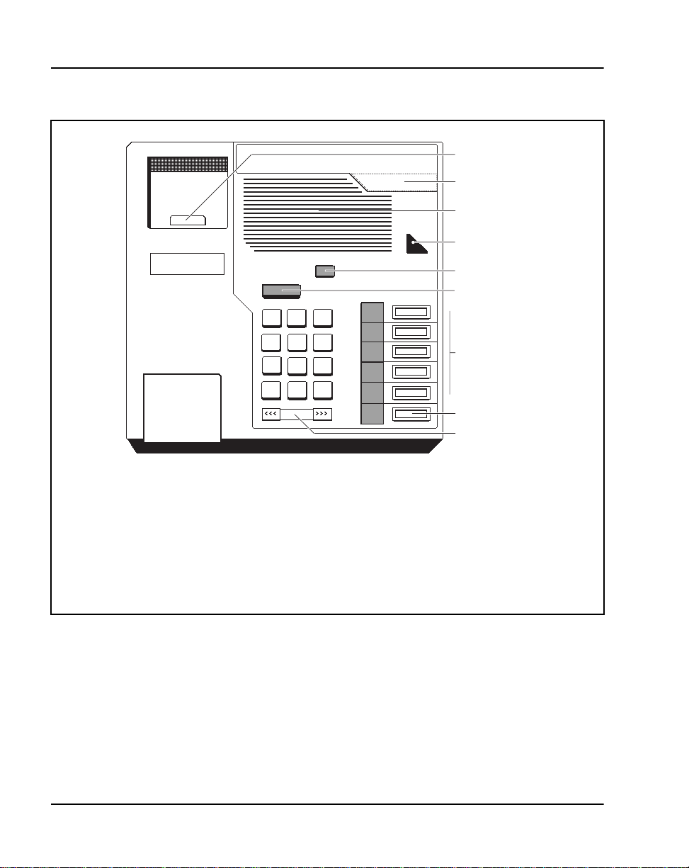
M2006—a single-line telephone with six programmable function keys. See
Figure 1.
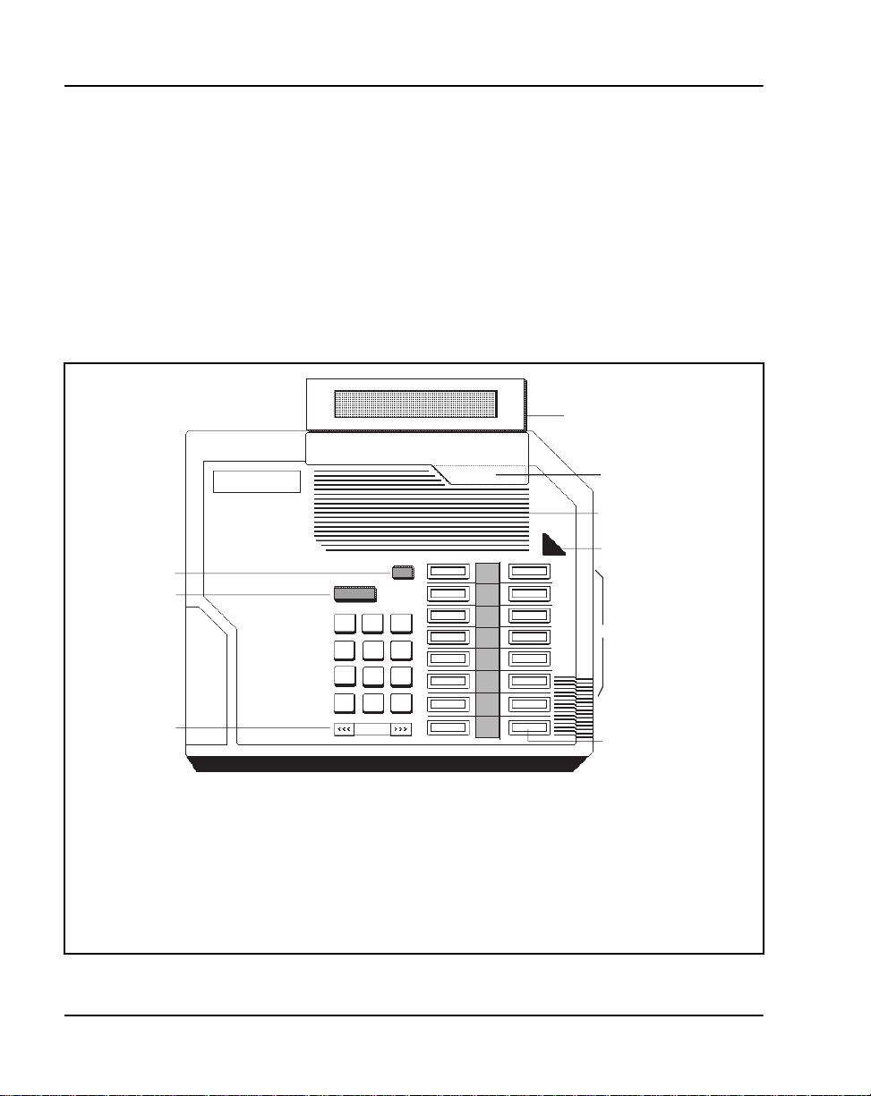
M2008/M2008HF—a multi-line telephone with eight prog ramma ble
function keys. Th e M2008HF contains an integrated Handsfree unit. See
Figure 2.
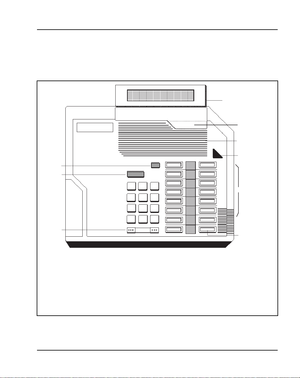
M2616—a high-performance multi-line telephone with 16 programmable
function keys and integrated Handsfree unit. See Figure 3.
Meridian 1 Telepho nes Description and Specifications
Page 14
Page 14 of 104 M2000 Series Meridian Digital Telephon es
Figure 1
M2006 telephone
Switchook
•
•
•
•
Dimensions:
Length: 8.42 in (216 mm)
Width: 8.42 in (216 mm)
Height: 3.61 in (92.6 mm)
•
•
Brandline insert
Speaker
Message Waiting
lamp
Rls key
Hold key
•
Function keys
and LCDs
•
•
DN
Volume
control
553-1850
Weight: approximately 2.65 lbs (1.1 kg)
553-3001-108 Standard 9.00 April 2000
Page 15

Figure 2
g
M2008/M2008HF telephone
M2000 Series Meridian Digit al Telephones Page 15 of 104
Filler plate
Brandline insert
witchook
Rls key
Hold Key
Volume
control
Dimensions:
Length: 8.42 in (216 mm)
Width: 8.42 in (216 mm)
Height: 3.61 in (92.6 mm)
Weight: approximately 2.65 lbs (1.1 kg)
Speaker
Message Waitin
lamp
Function keys
and LCDs
Prime DN
553-1851
Meridian 1 Telepho nes Description and Specifications
Page 16
Page 16 of 104 M2000 Series Meridian Digital Telephon es
M2016S—a secure telephone (Sec urity Group Class II approved
TSG-210291030), designed to provide on-ho ok se curity. It is simila r to the
M2616, with 16 programmable function keys, but has no Handsfree
capability.The M2016S uses relay circuitry that physically disconnects the
handset from t he telep hone circuit when the s witchhook is depresse d. The red
LED triangle lights steadily when the phone is not se cure . (The phone is not
secure when the handse t is off the hook, when the phone is ringing, or
whenever the handset/piezo relays are connected.) The red LED triangle
blinks when a message is waiting. See Figure 3.
Figure 3
M2616 and M2016S telephones
Rls key
Hold key
Display
Brandline insert
Speaker
Message Waiting
lamp
Function keys
and LCDs
Volume
control
Dimensions:
Length: 9.75 in (251 mm)
Width: 9.45 in (237 mm)
Height: 3.64 in (92.6 mm)
Weight: approximately 2.65 lbs (1.1 kg)
553-3001-108 Standard 9.00 April 2000
In-calls key
553-1853
Page 17
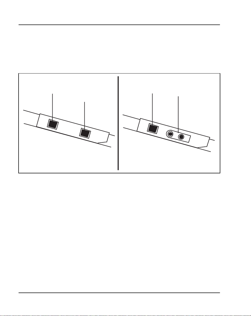
M2216ACD-1—a multi-line telephone for ACD operations See Figure 4. It
has 15 programmabl e function keys, the Speci al Applications Display
module, and two RJ-32 jac ks for modular electret heads ets. See Figure 5.
Figure 4
M2216ACD-1 and -2 telephones
Rls key
Hold key
M2000 Series Meridian Digit al Telephones Page 17 of 104
Display
Brandline insert
Speaker
Message Waiting
lamp
Function keys
and LCDs
Volume
control
In-calls key
553-1853
Dimensions:
Length: 9.75 in (251 mm)
Width: 9.45 in (237 mm)
Height: 3.64 in (92.6 mm)
Weight: approximately 2.65 lbs (1.1 kg)
Meridian 1 Telepho nes Description and Specifications
Page 18
Page 18 of 104 M2000 Series Meridian Digital Telephon es
M2216ACD-2 (retired)— a mul ti- lin e tel ephone fo r ACD operat ions. It has
15 programmable function keys and the Display module. It is similar to
model 1, but with one PJ-327 jack for a carbon agent heads et a nd one RJ-32
jack for an electret supervisor headset. See Figure 5.
Figure 5
M2216ACD-1 and -2 left side showing head set j acks
electret supervisor
headset jack
electret agent
headset jack
M2216ACD-1 (left side)
Note: If headset is des ired, the ampl ifi ed type is stron gly recomme nded.
electret supervisor
headset jack
M2216ACD-2 (left side)
carbon agent
headset jack
553-5060
553-3001-108 Standard 9.00 April 2000
Page 19

M2000 Series Meridian Digit al Telephones Page 19 of 104
M2216ACD Headset interface
Using the Program key, you can adjust the headset/handset interface of the
M2216ACD-1 to optimiz e performance.
The M2216ACD-1 is compatibl e with most headset s. Amplified headse ts are
strongly recommen ded. Three settings are provided:
• Interface 1 (i.e. Plantronics type )
• Interface 2 (Liberatio n )
• Interface 3 (Handset)
Note: It is recommended that the headset user try usi ng their headset
with each of the three settings to determine wh ich works best for the m.
Trial with both internal and external calls is also recommended in each
setting to determine optimum performa nce .
Note: When the amplified headset is used, there are two choices of
volume control: the rocker control on the tel ephone and the sw itch on th e
headset. The sett ings which provi de for the clearest communicati on with
the least amoun t of di stort ion are when the ampli fie r has a high er se tti ng
than the telephone volume control.
The supervisor and agent jacks are not interchangeable. A headset must be
plugged into the agent jack if the telephone is to receive ACD cal ls.
Note: Any recording device con nected to the receive path of an M2000
Series Meridian Digital Telephon e must meet these requirements:
• isolate power source from the headset /handset jack
• connect in parallel across pins 3 and 4 of the handset/headset jack
• load impedance at le as t 8K ohms across the audio band
Meridian 1 Telepho nes Description and Specifications
Page 20

Page 20 of 104 M2000 Series Meridian Digital Telephon es
Physical charact eristic s
Fixed keys
All of the M2000 Series Meridian Digital Telephones are equipped with the
following fix ed keys:
• Hold key
• Relea s e k ey
• Volume control key
Volume control key Pressing th e right “vol ume up ”* o r left “ vol ume down”
side of the key incre me ntally increases or decreases the volume for the tone
or sound that is currently active.
*All Meridian Digi tal Telephones, with the exception of the M2016S
manufactured after June 1996 are compliant with the HAC volume level
requirements issued by the FCC for handset volume control for the hearing
impaired. The highest volume level setting provides 13.5 dB over nominal.
The volume settings are retained for subsequent calls until new volume
adjustments are made. If the telephone is equipped with a Display module,
volume can be adjusted at any time with the se tting displayed on the screen
(in Program mode).
You can adjust the volume of the following tones while they are audible:
• ringing
• Handsfree (M2008HF/M2616)
• handset/headset
•buzz
• on-hook dialing
Note: When the telep hone is di sconn ecte d, all vol ume l evels wil l r et urn
to default values upon reconnection.
553-3001-108 Standard 9.00 April 2000
Page 21

M2000 Series Meridian Digit al Telephones Page 21 of 104
Message Wait ing lamp ke y Each M2000 Seri es Meridian Di gital Tele phone
has a red tria ngle in the upper ri ght-hand corner that li ghts bright ly to in dicate
a message i s wai ting. This LED is t he prim ary m essage wa it ing indica tor an d
lets you kno w a message is wa iting re gardle ss of whethe r the te lephon e ha s a
message waiting key/lamp pair. You must have Message Waiting allowed
Class of Service. See LD 11, X11 Admi nist rati on (553-3001-311).
If you do assign a message waiting key/lamp pair, there will be two
indications of a message waiting :
• the red Message Waiting triangle lights
• the LCD associated with the Message Waiting key flashes
You may assign an Autodial key that dia ls the message center (or voice mail
system) to avoid the double indication or have no key/lamp pair assigned to
the mess a g e center.
The Message Waitin g lamp is also used to indicate security of the M2016S.
The red LED triangle light s steadily when the phone is not secure . (The phone
is not secure when the handset is off the hook, when the phone is ringing, or
whenever the handset/piezo relays are connected.) The red LED triangle
blinks when a me ssage is waiting.
Handsfree/Mute key ( M2008HF & M2616 only) Handsfree is software
assignable on the M2008HF/ M2616. This all ows you to t alk to a nothe r party
without lifting the handset. Activate Handsfree by depressing the
Handsfree/Mute key (key 15, top left for M2616; key 6, below Program for
M2008HF) or by sele cting a DN wit hout lif tin g the hands et. Onc e Handsfre e
is activ ated, it can be deactivated by pi cking up the ha ndset or by ending the
call using the Relea se (Rls) key. If Handsfree is not software ass igned, you
can assign any other feature to the “Handsfree” key.
Note: Software Control - CLS Class of Service for M2008HF
The Class of Service fe ature cons istent wi th M2616 Handsfre e control allows
system administrators to enable/disable the Handsfree option on the
M2008HF (Handsfree) telephone via software. M2008HF telephones ship
from the factory with a hardware jumper enabled to allow the Handsfree
option for existing software releases.
Meridian 1 Telepho nes Description and Specifications
Page 22

Page 22 of 104 M2000 Series Meridian Digital Telephon es
Release 21.4 1 and later software will now override the har dware setting and
default to Handsfree denied (HFD.) If the handsfree option is des ired, the
system administrator simply enables Handsfree via a Class of Service prompt
(HFA) included on Overlay 11 programming for the M2008 telephones
(consistent with M2616).
Service Change Parameters
LD 11 – Allow/Deny Handsfree for M2008HF
Prompt Response Description
Req: New/Chg
Type M2008 Aries
CLS (HFD)
HFA
Digital Telephone
Handsfree Denied
Digital Telephone
Handsfree Allowed
MAT
X11 Release 21.41 in troduced support for the Mer idian M2008HF set by
providing a “Cla ss of S ervice” change for Overlay 11 th at allows handsfree
operation on set type M2008. If MAT is equipped, a patch is required for
MAT Release 4.02 to support this feature. Sites running MAT Release 3
cannot be pat ched to support this operation. Sites with MAT Rel ease 3 must
upgrade to MAT Release 4 and obtain a patch to support M2008 handsfree
operation. The patch is available from ETAS.
Handsfree operates as if an off-hook operation had been performed. For
example, when the telephone is idle, press ing the Handsfree/Mute key turns
on the integrated Handsfree and s elects a DN (depending on line selection as
assigned through COS), a llowing the user to make a call. When a ca ll comes
in to an M2008HF/M2616 and the set is ringing, pressing the Handsfree/Mute
key turns on the Handsfree and allows the user to answer the incoming
(ringing) call (depending on COS-assign ed line select ion) witho ut picking up
the handset.
553-3001-108 Standard 9.00 April 2000
Page 23

M2000 Series Meridian Digit al Telephones Page 23 of 104
Features keys
Each M2000 Series Meridian Digital Telephone has a number of
programmable keys with LCD indicators that can be assigned to any
combination of directory n umbers and feat ures (only one DN for the M2006).
The lower right-hand key (key 0) is reserved for the Primary DN.
Note 1: When equipped with a Display module, Meridian
Communications Adapter (MCA), or Meridian Programmable Data
Adapter (MPDA), key 07 is autom atically assigned as the Program key
and cannot be changed. Key 0 5 becomes t he Prog ram ke y on the M2 006
if equipped with the MCA or MPDA.
See “Data options” on page 85 for more information on the MCA and
MPDA.
Note 2: The M2006 i s a singl e-lin e telephone and acc epts only on e DN.
The remaining fi ve key/lamp pairs can be assign ed any featu re that is not
considered a DN, such as Transfer, Call Forward, or Conference.
Features that cannot be assigned are those that are considere d DNs:
Voice Call and two-way Hot Line, for example. Attempting to assign
more than one DN to the M2006 causes the telephone to disa ble itself and
all LCD s li g h t s te adily. It w ill retu r n to it s no r m al operating sta te when
service change rem oves all secondary DNs.
LCD indicators support four key/LCD states:
Function LCD state
idle off
active on (ste ad y )
ringing flash (60 Hz)
hold fast flash (120 Hz)
* An indicator fas t flashe s when you h ave presse d a feat ure key bu t have
not completed the procedure necessary to activate the feature.
Data Options
See “Data options” on page 85 for more information on the MPDA and MCA.
Meridian 1 Telepho nes Description and Specifications
Page 24

Page 24 of 104 M2000 Series Meridian Digital Telephon es
Software requirements
M2000 Series Meridian Digital Telephones are supported by X11 release 14
and later softwa re. The option num ber for the M2000 Ser ies Meridi an Digital
Telephones is 170. The mnemonic is ARIE. The DSET package (88) and the
TSET pack a g e (89 ) are re q u ire d.
Modular options
This sectio n describes the modular options available for M2000 Series
Meridian Digi tal Te lephones. Tab le 1 lists the features and option al hardware
available f or each telephone.
Table 1
Hardware features and options
M2006
Programmable
keys
Handsfree
microphone
Optional hardware available:
Display x x standard standard
Key Expansion
Module
Meridian
Communications
Adapter (MCA)
Meridian
Programmable
Data Adapter
(MPDA)
External alerter
interface
In this table, x indicates available features for the telephone type listed in the top row.
Note:
6 8 16 16 15 15
x x x x x
x x x x x
x x x x x
M2008/
M2008HF
standard
on the HF
M2616 M2016S
standard
x x x
M2216
ACD-1
M2216
ACD-2
553-3001-108 Standard 9.00 April 2000
Page 25

Table 1
Hardware features and options
M2000 Series Meridian Digit al Telephones Page 25 of 104
M2006
Analog Terminal
Adapter (ATA)
Brandline insert x x x x x x
In this table, x indicates available features for the telephone type listed in the top row.
Note:
x x x x x
M2008/
M2008HF
M2616 M2016S
M2216
ACD-1
M2216
ACD-2
Note: If the telephone is equipped with a Display, Meridian
Programmable Data Adapt er, or Meridi an Communicati ons Adapter, t he
number of programmable keys is reduced by one, as key 07 (key 05 on
M2006) automatically assumes the Program function.
For installation info r mation, see Telephone and Attendant Console:
Installation (553-3001-215). See “Data optio ns” on page 85 for more
information on the MPDA and MCA.
Display module
A two-line (24 charact ers per line) Dis play module provid es system prompts ,
feedback on active features, an d valuable calling party information . In
addition, you can modify various telephone features such as volu me and
screen contrast using the Program key (top right function key). You can
enable a Call Timer, which times calls made or r eceived on the prime DN.
Note: The display module is not supported on the M2006.
The displays previ ously available (NT2K24WA, NT2K25YL, and others)
have been replaced b y displa y NT2K28xx whi ch elimina tes a da ughter board.
Two new screens have also been added to support ACD applications:
• Logged Out
•Not Ready
Note: It is possible to adjust the Display screen contrast so that it is too
light or too dark to rea d. If you cannot read the Displa y, disconnect and
then reconnect the line cord to retu r n to the default se ttings.
Meridian 1 Telepho nes Description and Specifications
Page 26

Page 26 of 104 M2000 Series Meridian Digital Telephon es
Program key
The Program key i s automat ically a ssigned t o M2000 Series Me ridian Digi tal
Telephones wit h Display, Meridian Communications Adapter (MCA), or
Meridian Progra mmable Data Adapter (MPDA) added. You can change a
variety of display features such as screen format, contrast, and language. It
also lets you c hange data parameters , s uch as transmission spe ed and parity,
on the MPDA and MCA (if equipped).
The upper right-ha nd key (key 05 on the M2006 and key 07 on all others)
automatically becomes the Pr ogram key when Display, MCA, or MPDA is
configured wit h t he tel ephone. The Program ke y is local to the te lephone and
shows blank when you print key assignments in LD 20.
See “Data options” on page 85 for descriptions of the MCA, MPDA and ATA
and their requirem ents.
External Alerter interface
The External Alerter Board provides an interface to standard remote ringing
devices, such as a ringing unit instal led in a location separate from the
telephone. The External Alerter interface is not the remote ringer itself, but
provides acces s to standard, off-the-sh elf remote ringi ng devices. The Alerter
Board requires additional power. See “Pow er requirements” on page 32.
You can program the Extern al Alerter interface to activate a ringer (or light)
when the telephone rings or when the telephone is in us e (off-hook).
For informati on on ins talling a nd sett ing up the Externa l Alerter, s ee “Add-o n
modules” in Telep hone and A ttendan t C onsole : I nstal lat ion (553-3001-2 15).
Key Expansion Module
A modular 22-key uni t can be attache d to any 16-key M2000 Ser ies Meridi an
Digital Telephone except M2016S. See Figu re 6. The extra keys can be
assigned to any combination of lines and features. You can add up to two
expansion modu les to 16-key telephones, providing a total of 60 line/ feature
keys. You will need a separate footstand for the module(s), one for a single
module, one for a double. See “Ordering information” on page 39. The
expansion module may require ad ditional power. See “Power requirem ents”
on page 32.
553-3001-108 Standard 9.00 April 2000
Page 27

M2000 Series Meridian Digit al Telephones Page 27 of 104
The Key Expansion Modu le connects to the telephone through a cable
running from the base of the telephone. It is physically connected to the
telephone by the footstand. NT2K22VH or later vintage key lamp modules
are required for CISPR22, Class B compliance.
Brandline insert
The filler plate on the telephone or Displa y mod ule contains a removable
insert design ed to accommodate custom labeling. You can order blank
Brandline Inserts and have a printer silk screen your company logo on them.
Brandline Ins erts snap easily into and out of the filler plate.
M2006/M2008/M2008HF/M2216ACD/M2616 telephones
You can use an electret headset in the handset port of the M2006, M2008,
M2008HF, M2616, and M2216ACD telephones. The amplif ier must draw
less than 400 micro amps from the telephone jack.
The headset should be designed to work with a te lephone jack with these
characteristics:
Transmit interface: +5 V through 10K DC bias resistance with maximum
current of 500 micro amps. The differential input impedance is 10K ohms.
Connects to pi ns 2 and 5 of the handset jack.
Receive interface: single ended output with output impedance of 180 ohms.
Connects to pi ns 3 and 4 of the handset jack.
Meridian 1 Telepho nes Description and Specifications
Page 28
Page 28 of 104 M2000 Series Meridian Digital Telephon es
Figure 6
M2616 with Display module and Key Expans ion module
553-1857
553-3001-108 Standard 9.00 April 2000
Page 29

M2000 Series Meridian Digit al Telephones Page 29 of 104
M2000 Series Meridian Digital Telephone relocation
This section describes how to reloc ate an M2000 Series Meridian Digital
Telephone and its associated dataport Terminal Number (TN) without the
intervention of a craftsperson.
Modular Tel ephone Re locat ion is d esign ed s pecifi call y for th e M2 000 Serie s
Meridian Digital Telephones and is an enhancement to Automatic Set
Reloca tion. If dataport TN inform ation exists for the terminal, it is
automatically relocated when the telephone is relocated.
When a telephone is relocated-out, a relocation block is built to store the
relocation information in the protected data area. The relocation block
includes the old TN, the terminal ID information, the serial number of the
telephone, and other information.
This feature uses the unique serial numbe r and te rmi nal ID of the M2000
Series Meridi an Digital Telephone to identify the terminal being relo cated
and to reduce the number of manual steps needed for relocation.
See Automatic Set Re loc atio n in X11 Features and Services (55 3-3001 -306)
for complete details.
How to relocate an M2000 Series Meridian Digital Telephone
1 Go off-hook, receive dial tone, and enter Reloc ation Code (either SPRE
+81 or Flexible Fea ture Code).
2 Enter optional security code as defined in OVL 15 (a burst of tone
confirms that the telephone is relocat ed-out).
3 Take it to the new location and plug it in (a confirmation buzz from the
speaker indicates the telephone is in service).
Meridian 1 Telepho nes Description and Specifications
Page 30

Page 30 of 104 M2000 Series Meridian Digital Telephon es
Specificatio ns
This sectio n lis ts the specifications required for M2000 Series Meridian
Digital Telephones.
Environmental and safety considerations
All digital telephones and their as sociated options meet the requireme nts of
the Electronic Industries Association (EIA) specification PN-1361.
Temperature and humidity
Operating state:
Temperature range 0° to 50°C (32° to 104°F)
Relative humidity 5% to 95% (noncondensing). At temperature s
above 34°C (93°F) relative humidity is limited
to 53 mbar of water vapor pressure.
Storage:
Temperature range –50° to 70°C (–58° to 158°F)
Relative humidity 5% to 95% (noncondensing). At temperature s
above 34°C (93°F) relative humidity is limited
to 53 mbar of water vapor pressure.
Electromagnetic interference
The radiated and conducted electromagnetic interferenc e meets the
requirements of Subpart J of Part 15 of the FCC rules for clas s A computing
devices.
NT2K model sets with all options meet CISPR2 2, Class B requirement s.
Local alerting tones
Each telephone provides four alerting tones and a buzz sound. The system
controls t he ringing cadence by sending tone-ON and tone-OFF messages to
the telephone. The alerting tone cadences cannot be changed from the
telephone but can be altered for individual M2000 Series Meridian Digital
Telephones by software controlled adjustments in the system. S ee X11
Administration (553-3001-311). All other te lephony tones, such as dia l tone
or overflow, are provided by the Meridian 1 from a Tone and Digit Switch.
553-3001-108 Standard 9.00 April 2000
Page 31

Alerting tone characteristics
The tone frequency combinations are as follows :
Tone Frequencies Warble Rate (Hz)
1 667 Hz, 500 Hz
2 667 Hz, 500 Hz
M2006/M2008/M2008HF:
3 1600 Hz, 2000 Hz
4 1600 Hz, 2000 Hz
M2016S/M2616/M2216ACD:
3 333 Hz, 250 Hz
4 333 Hz, 250 Hz
A 500 Hz buzz signal is provided for incoming call notification while the
receiver is off-hook.
Line engineering
M2000 Series Merid ian Digital Telephones us e twisted pair wiring on
transmiss ion lines selecte d by the rules given in Digital Tele phone Line
Engineering ( 553-22 01-180). The maximum pe rmissi ble lo op le ngth is 3 500
ft. (1067 m), assuming 24 AWG (0.5 mm) standard twis ted wire with no
bridge taps. A 15.5 dB loss a t 256 kHz defines the loop length limit. (Longer
lengths are possible, dependi ng on the wire’s gauge and ins ulation.) Table 2
gives detailed information on loop lengths.
M2000 Series Meridian Digit al Telephones Page 31 of 104
5.2
2.6
5.2
2.6
5.2
2.6
Table 2
Loop lengths for digital telephones
QPC578 A and B QPC578 C + NT8D02
PVC insulated cable (polyvinyl chloride)
22 or 24 AWG 100–3000 ft.
(30.5–915 m)
26 AWG 100–2100 ft.
(30.5–640 m)
Note 1:
Note 2:
No bridge taps or loading coils are allowed.
Effect of line protector at MDF reduces loop length by 500 ft.
0–3500 ft.
(0–1067 m)
0–2600 ft.
(0–945 m)
Meridian 1 Telepho nes Description and Specifications
0–3500 ft.
(0–1067 m)
0–2600 ft.
(0–793 m)
Page 32

Page 32 of 104 M2000 Series Meridian Digital Telephon es
Note: Use only the line cord provided with the M2000 Series Meridian
Digital Telephone. Using a cord designed for other digital tele phones
could result in damage to the cord/loss of set func tionality.
Power requirements
The M2006, M2008, M2008HF, M2616 (basic configurat ion and with
Display module), and M2216ACD-1 are loop powered. Loop power,
originating in the ISDLC or t he DLC, cons ists o f a 30 V d c power source and
assumes a 3500 ft. (1219 m) maximum loop length of 24 AWG (0.5 mm)
wire and a minimum 15.5 V dc at the telephone terminals.
Note: The loop lengt h lim it is defined by a 15.5 dB loss at 256 KHz.
Longer leng ths can be deter mined using the wi re’s gaug e and insul ation.
The Handsfree feature , which is integrated into the M2008HF/M2616,
requires no additional power.
Some configurations of telephones and options need more than basic loop
power to operate. Table 4 lists the types of M2000 Series Meridian Digital
Telephones for NTZK telepho nes (Ta ble 4 for NT2K telephon es) and shows
when additiona l power is needed to operate the telephone or its optional
hardware. Power Supply Boards come installe d in factory-assembled
configurations that require additional power.
Note 1: If a power fa ilure occ urs, configura tions t hat require lo op power
will continue to work only if the system has battery backup. Only those
options that require additional power will cease to function.
Note 2: During a power failure, the carbon agent headset on the
M2216ACD-2 will fail and the electret supervisor’s ja ck c an be used as
an agent jack. If no headset is plug ged in to the electret jack during powe r
failure, the call is dropped, and the agent is logged off and must log in
again once the electr et headset is plugg ed in. When power is re stored, the
carbon jack returns aut om atically. Power supply board
The power supply option consist s of a power supply board th at mounts in side
the telephon e, coupled with an external wall-mount transformer or cl os et
power supply that provides power to the power supply board. The power
supply board receives its power through pins 1 and 6 of the line cord.
553-3001-108 Standard 9.00 April 2000
Page 33

M2000 Series Meridian Digit al Telephones Page 33 of 104
Table 3
NTZK model Power requirements, M20 00 Series Meridian Digital Telephone sets
T elephone type Loop power
Additional power
(Power Supply Board)
M2006 Basic configur ation MPDA, External Al e rter Inte rface,
MCA (optional),
M2008 Basic configur ation Any option(s)
M2616 Basic configurati on (with Handsfree)
and Display.
MPDA, Key Expansion Module,
External Alerter Interface, MCA
(optional)
M2016S N/A Basic Configur ati on
M2216ACD-1 Basic configuration (wit h Display) MPDA, Key Expansion Module,
External Alerter Interface, MCA
(optional)
M2216ACD-2 N/A Any configuration
Table 4
NT2K model Power requirements, M2 000 Series Meridian Digital Telephone sets
Additional power
T elephone type Loop power
(Power Supply Board and
T ransformer)
M2006 Basic configur ation Any option(s) * (MPDA, External
Alerter Interface, MCA)
M2008/M2008HF Basic and Display configuratio ns MPDA, External Al e rter Inte rface
M2616 Basic, Display, and Handsfree
configurations and Key Expansion
MCA, MPDA, External Alerter
Interface, MCA
Module(s)
M2016S N/A Basic configur ation
M2216ACD Basic configur ations (with Display)
Key Expansion Module(s).
*No display can be added to the M2006 set.
MPDA, Key Expansion Module,
External Alerter Interface, MCA
Meridian 1 Telepho nes Description and Specifications
Page 34

Page 34 of 104 M2000 Series Meridian Digital Telephon es
When installin g an MCA or MPDA to NTZK or NT 2K phone sets wi th a date
code prior to January 1998 a Power Option board is required, along with an
additional power source.
When installing an MCA in an NT9K phone se t or an NT2 K with date code
of January 1998 you will only install the MCA (an additional Power Option
board and Jumper board is not required).
The power supply board co nnec ts to the telephone through a 14-pin bottom
entry connector.
Refer to Table 3 and Table 4 for power supply board requirements.
Local plug-in transformer (A0367335)
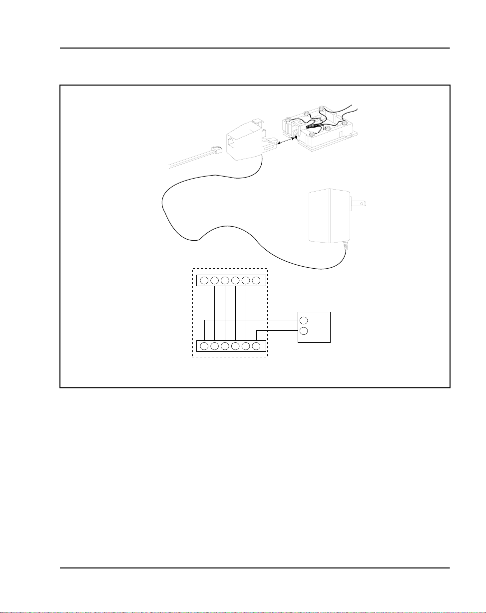
A single winding transf orm er equipped with a 10 ft. (3 m) cord of 22 AWG
two-conductor stranded and twisted wire with a modular RJ-11 duplex
adapter can provide the additi onal power needed to ope rate the tele phone and
its options. (See Figure 7).
CAUTION
Do not plug any equipment (computer, modem, or LAN card) other
than the M2000 Ser ies Meridian Digita l Telephone into the RJ-11
transformer adapter, as damage to equipment may resul t.
553-3001-108 Standard 9.00 April 2000
Page 35
M2000 Series Meridian Digit al Telephones Page 35 of 104
Figure 7
Configurati on of local plug-in transform er
Adapter jack
6-conductor
line cord
from telephone
123456
Plug
123456
Jack
Adapter
Adapter
plug
1
2
Wall
transformer
(110 V or 220 V)
To IDF
553-1855
Meridian 1 Telepho nes Description and Specifications
Page 36

Page 36 of 104 M2000 Series Meridian Digital Telephon es
120 V transformer (AO367335 or equiva lent) The following minimum
specific ations must be met by this tr ans f ormer:
Input voltage 120 V ac/60 Hz
No load output voltage 29 V ac maximum
Voltage at rated current 26.7 V ac minimum
Rated load current 700 mA
240 V transformer (AO367914 or equiva lent) The following minimum
specifications have to be met by this transformer:
Input voltage 240 V ac/50 Hz
No load output voltage 29 V ac maximum
Voltage at rated current 26.7 V ac minimum
Rated load current 700 mA
Note 1: You cannot wall mount the telephone over the wall jack when
using a transformer be ca use of the size of the RJ-11 adapter. Hang it
above or to the side of the jack and run the line and power cords to it.
Note 2: The above-mentioned transformers can also used with outlets
identified as 110V or 220V.
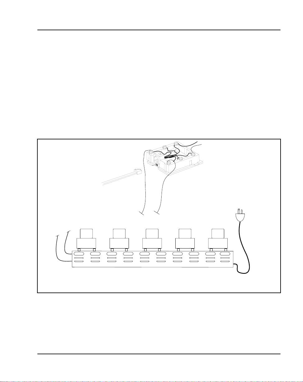
Closet Power Supply
Closet power can be obtai ned from an AC transformer for loops of 100 ft.
(30 m) or less, or a DC transformer for loop leng ths of 650 ft. (198 m) or less.
An equivalent powe r source can be used but must be UL listed to provide
isolation of outputs to the terminal. See Figure 8.
When using closet power, do not plug the modular connector into any
equipment (computer, modem, or LAN card) other than the M2000
Series Meridi an Digital Telephone, as damage to equipment may
result.
553-3001-108 Standard 9.00 April 2000
CAUTION
Page 37
Note 1: All terminals must be isolated from the input winding and each
terminal must be isol ated from all other terminal windings. A separate
winding is required for each terminal, and grounds should not be
connected.
Note 2: The QUT1 closet power supply source is not compatible with
M2000 Series Meridian Digital Telephones.
The AC source should be ra ted at 29 V ac, 700 mA isolated. The DC sourc e
should be rated at 42 V dc, 300 mA isolated, with current lim iting output of
1 amp.
Figure 8
Closet Power Supply configuration
6-conductor
line cord
from telephone
M2000 Series Meridian Digit al Telephones Page 37 of 104
1
Ring (g)
4
5
6
Connects to an
isolated output
W
BL
Closet Power Supply
(Shumway SBI 221-25 or equivalent)
Meridian 1 Telepho nes Description and Specifications
553-1856
Page 38
Page 38 of 104 M2000 Series Meridian Digital Telephon es
Handset s
This sectio n provides ordering inform ation for M2000 Series Meridian
Digital Telephone handsets.
Table 5
Order codes f or new handsets for M200 0 Series Meridian Digital
T elephone sets, model NTZK
Description Order Code
Legacy handset, Black NT0C09EA03
Legacy handset, Ash NT0C09EA35
Legacy handset, Gray NT0C09EA93
Handsets designed for NT2K sets (Global handset) will not meet product
Note:
transmission/rece ption specificat ions if used with N TZK sets.
Table 6
Order codes f or new handsets for M200 0 Series Meridian Digital
T elephone sets, model NT2K
Description Order Code
Global handset, Black NT0C09EK03 / A0400786
Global handset, Ash NT0C09EK35 / A0400787
Global handset, Gray NT0C09EK93 / A0400790
Note 1:
transmission/reception sp ecifications if used with NT2K sets.
Note 2:
will not meet product transmission/reception specifications if used with NT2K sets.
Note 3:
AF versions) telephones.
Handsets designed for NTZK sets (Legacy handset) will not meet product
Noisy Location, Push-to-Talk, Push-to-Mute, and Mercury Switch handsets
Global handsets are not compatible with M1250 or M2250 (AE or current
553-3001-108 Standard 9.00 April 2000
Page 39

Ordering information
Refer to the Nortel Networks price book, or contact your Nortel Networks
representative for specific ordering codes.
Table 1, “Hardware features and options,” on page 24 lists the hardware
options that you can purchase separately.
For ordering configurations for M2000 Series Meridian Digital Telephones
and accessor ies, see the current pr ice book.
See Equipment Identification (553-3001-154) for more information.
M2000 Series Meridian Digit al Telephones Page 39 of 104
Meridian 1 Telepho nes Description and Specifications
Page 40

Page 40 of 104 M2000 Series Meridian Digital Telephon es
553-3001-108 Standard 9.00 April 2000
Page 41

58
Page 41 of 104
M2317 Telephone
Content list
The following ar e th e topics in th i s section:
• Reference list 41
• General features 42
• Physical characteristics 43
• Firmware features 52
• Software requirements 52
• Specificat ions 54
• Safety considerations 54
• Environmental considerations 54
• Dimensions and weight 55
• Line engineering 55
• Power requirements 55
• Ordering information 58
Reference list
The following are the references in this section:
• Digital Telepho ne Line Engineering (553-2201-180)
• M2317 Quick Reference Car d
Meridian 1 Telepho nes Description and Speci fications
Page 42
Page 42 of 104 M2317 Telephone
Functional description
This section provides feature and software requirement information for the
M2317.
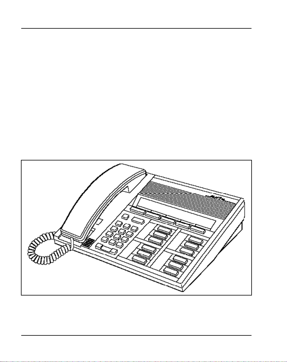
General features
The M2317 telephone ha s t he following general features:
• A built-in, two-line (40 character s per line) Liquid Crystal Dis play
(LCD) screen and integrated Handsfree.
• A telephone line cord and the handset cord equipped with standard
modular connect ors at each end, whic h permits quick re place ment when
required.
Figure 9 shows the M2317 telephone.
Figure 9
M2317 telephone
553-3001-108 Standard 9.00 April 2000
553-5852
Page 43

Physical charact eristic s
The M2317 teleph one has the following physical characteristics.
Housing
The housing of the M2317 digita l telephone consist s of a molded plastic base
and faceplate. The display module and the main circuit board are fastened t o
the undersid e of the f acepl ate. T he As ynchrono us Da ta Opt ion (ADO) ci rcuit
board, if equippe d, is mounted inside the base.
Keys
The M2317 telephon e is equi pped with 17 fea ture keys (s ee Figure 10) which
are ar ranged as f o llows:
Fixed keys
There are four keys to whic h a fixed func tion is assi gne d. They consi s t of the
following:
• 1 Releas e k ey
•1 Hold key
• 1 Volume control key (with 2 toggle positions)
• 1 Handsfree/Mute key (with associated LCD indicator)
M2317 Telephone Page 43 of 104
Feature keys
There are 11 progra mmable line/feature keys on the telephone face plate. Each
has an associated LCD indicator. Lines and features are assigned to these keys
by service chan ges in the system software . A maximum of ten voice Direc tory
Number s and spec ifi c featu res su ch as, Au to Answ erbac k, Call Waitin g, Dial
Intercom, and Dis play can be assigned.
Alphanumeric display screen and softkeys
The M2317 telephone is equipped with a two-line (40 characters per line
capacity) Liquid Crystal Display (LCD) screen and five LCD-labeled
softkeys loca ted immediately beneath the display screen.
The 155 x 15 mm (6 x 0.6 in) LCD scree n has a capacity o f 80 charac ters (two
lines of 40 charact ers each). The first line displays date and time during the
idle state, incoming call identification, feature icons, user prompts, and
messages, where as the second li ne disp lays the labels for t he softkeys (se ven
characters per k ey ).
Meridian 1 Telepho nes Description and Specifications
Page 44

Page 44 of 104 M2317 Telephone
There are f ive softkeys, whic h are counted one t o five from lef t to right. The
fifth softkey (“more…”) is used to scroll to a second layer fea ture menu
whenever there are more softkey-assigned features available for the active
telephone sta te. Pressing the “more…” key will bring up the labels for the
remaining functions. Softkey label positions on the display screen are fixed
by the M2317 telepho ne firmware and cannot be changed by the user.
Each softkey has a seve n-character-wide labe l on the display immediate ly
above the key. The labels change as the available features change. For
example, a softkey could access one feature in the idle state and a different
featur e in th e ac tive stat e.
Handsfree key
When Handsfree is on, you can talk to another party without lifting the
handset. Handsfree can be activat ed by pressing the Handsfree/Mute key, or
by pressing a DN ke y without lifting the handset. The Handsfree/Mute L CD
indicator shows the status of the Handsfree. Once Handsfree is activated, it
can be deactivate d by picking up the handse t or by pressing the Relea se (RLS)
key.
Handsfree operates as if an off-hook operation had been performed. For
example, when the telephone is idle, press ing the Handsfree/Mute key turns
on the integrated Handsfree and s elects a DN (depending on line selection as
assigned through COS), a llowing the user to make a call. When a ca ll comes
into an M2317 and the set is ringing, pressing the Handsfree/Mute key turns
on the Handsfree and allows the user to answer the incoming (ringing) call
(depending on COS-assigned line selection) without picking up the handset.
The M2317 provides independent volume adjustments for Handsfree,
handset, and alerting tone volumes (on-hook dialing and buzz). For detailed
adjusting information, refer to the M2317 Quick Reference Card.
553-3001-108 Standard 9.00 April 2000
Page 45
LCD indicat ors
LCD indicators support the following four ke y/LCD states:
Function LCD state
idle off
active on (steady)
ringing flash (60 Hz)
hold fast flash (120 Hz)
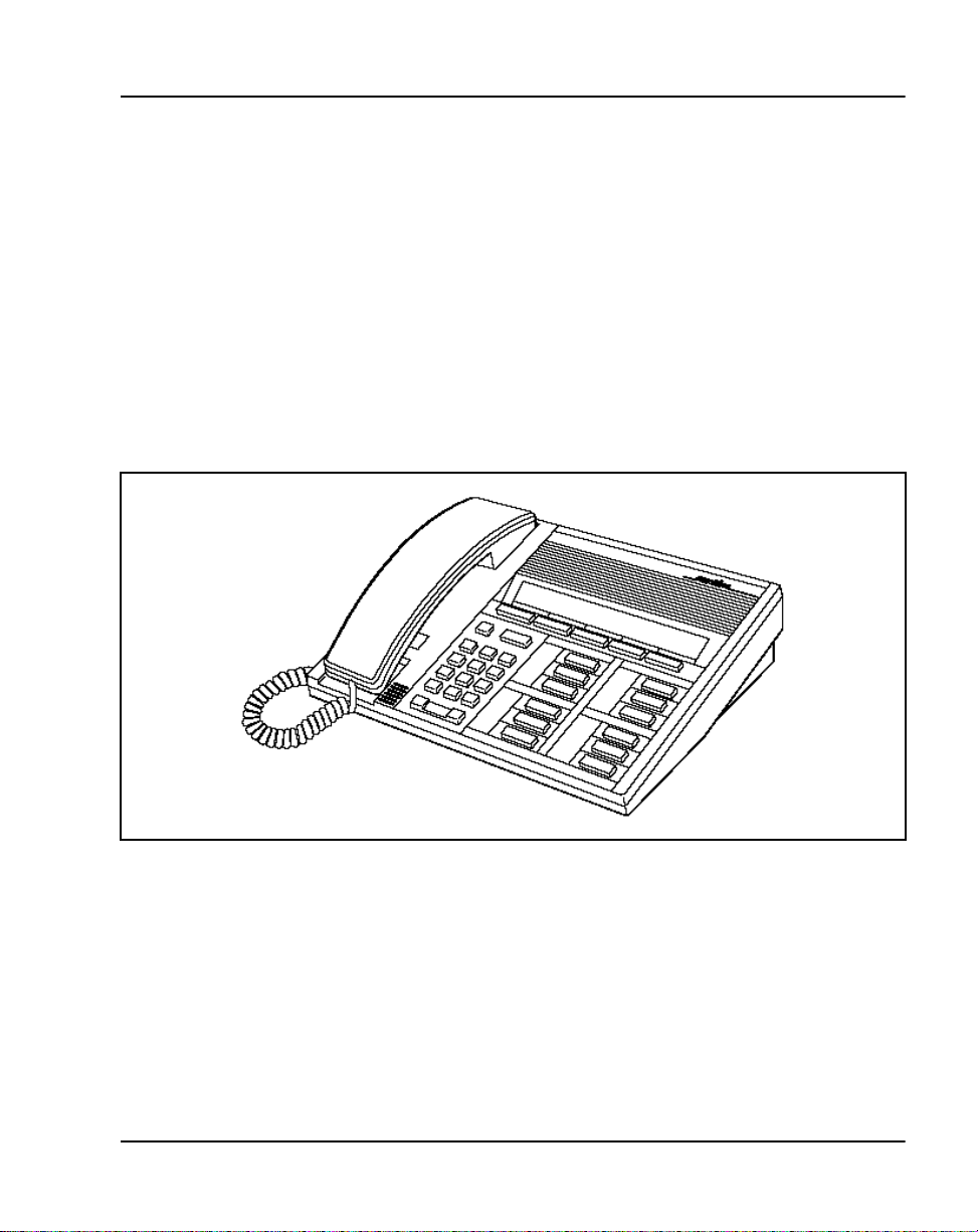
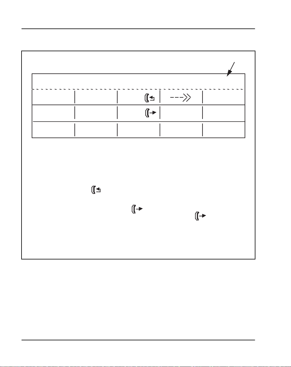
The followin g figures show the M2317 ke y layout a nd the different telephone
states that can be displayed on the M2317 screen.
Figure 10
M2317 telephone—key identification
M2317 Telephone Page 45 of 104
553-5852
Meridian 1 Telepho nes Description and Specifications
Page 46
Page 46 of 104 M2317 Telephone
Figure 11
M2317 screen display—available idle state features
Displays Month, Day, Hour, Minutes
MMM DD HH : MM
SAVED # LAST #
HELD #
RLSDATA
Note 1:
Note 2:
Note 3:
Note 4:
Note 5:
Note 6:
Only one row of softkey labels is displayed at a time. Additional rows are
accessed by operating the "more..." softkey. The five softkeys are located
beneath the screen display in line with each displayed label.
The HELD # softkey label is displayed on the screen only when there is a
held conference/transfer call.
The CANCL softkey label is displayed on the screen only when the "Ring
Again" feature has been activated.
The FORWARD and CHECK (Check Call Forward) labels are mutually
exclusive; the FORWARD key label changes to CHECK when calls are
forwarded.
The RLSDATA label is displayed only when there is an active data call.
The - - ->> key is only offered when CPND is used.
FORWARD
DATA
CANCL
CHECK
SPEED
TIMER
FRENCH
more...
more...
more...
553-3219
553-3001-108 Standard 9.00 April 2000
Page 47
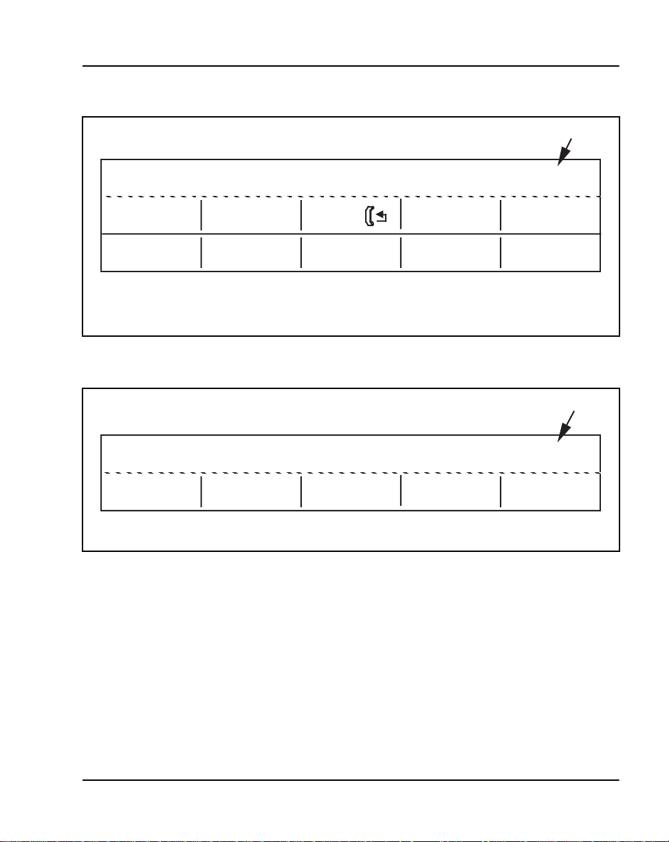
Figure 12
M2317 screen display—dial tone state
M2317 Telephone Page 47 of 104
Displays Month, Day, Hour, Minutes
MMM DD HH : MM
SAVED # CALL
SPEED #LAST # more...
MESSAGE ACCOUNTPICKUP more...
Note:
Figure 13
M2317 screen display—dialing state
Only one row of softkey labels is displayed at a time. The second row
is accessed by operating the "more..." softkey. The five softkeys are
located beneath the screen display in line with each designation.
Displays Month, Day, Hour, Minutes
3
MMM DD HH : MM
553-5101
553-5102
Meridian 1 Telepho nes Description and Specifications
Page 48
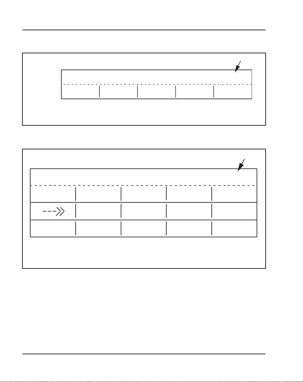
Page 48 of 104 M2317 Telephone
Figure 14
M2317 screen display—ringback state
Displays Day, Month, Hour, Minutes
Calling
Party
(Ringback
screen)
Figure 15
M2317 screen display—available establ ished state features
3021
SAVE #
Note:
The softkey label display on the called party's screen is the "Idle State" screen.
Elapsed Timer (Hours: Minutes : Seconds)
3021
CONFER
VMSG
Note:
Only one row of softkey labels is displayed at a time. Additional rows
are accessed by operating the "more... " softkey. The five softkeys
are located beneath the screen display in line with each designation.
PARK
TIMER SAVE #TRANSFR
PRIVREL CHARGE
DD MMM HH : MM
553-5103
H : MM : SS
more...
more...
more...
553-5104
553-3001-108 Standard 9.00 April 2000
Page 49
M2317 Telephone Page 49 of 104
Saved#, LAST#, CALL ,
SPEED#, more..., MESSAGE,
PICKUP, ACCOUNT, more...
Not all t h e features listed in Table 7 are necessarily prov id ed for ea ch
custo me r. Ch eck only th o se f eatures that are enab led in accor d an ce with the
work order.
The - - ->> symbol display is associated with the Call Party Name Display
(CPND) feature. CPND is only available with software X11 release 10 or
later an d must be enabled be fore it can be accessed.
Table 7
M2317 states and assoc iat ed softkeys (Part 1 of 3)
Screen state State Softkey display
Idle On-hook, voice or data
Dialtone Ready to transmit dialed digits
(voice)
Intercom dialtone Ready to transmit dialed digits for
an intercom call (voice)
Dialing Transmitting dialed digits no softkeys shown
Private Line dialing Transmitting dialed digits on a
private line (voice)
Busy Called party off-hook (voice) RINGA GN, SAVE#
Reorder C a lled par t y is unava ila ble (vo ic e ) no softkeys shown
Ringback Called party is ri ng ing (vo ice) SAVE#
ERWT call back Initial set of ESN routes not
available. Set gets Expensive
Route Warning Tone (voice).
Saved#, LAST#, CANCL ,
--->, more..., HELD#,
FORWARD, CHECK ,
TIMER, more..., RLSDATA,
DATA, SPEED
PICKUP
SAVED#, LAST#
RINGAGN, SAVE#
Meridian 1 Telepho nes Description and Specifications
Page 50

Page 50 of 104 M2317 Telephone
SAVED#, LAST#, CALL ,
SPEED, ACCOUNT
Table 7
M2317 states and assoc iat ed softkeys (Part 2 of 3)
Screen state State Softkey display
Established Voice connection made CONFER, TRANSFR, TIMER,
SAVE#, more…, –––>>,
PARK, PRIVREL, CHARGE,
more…, MESSAGE, more…
Intercom established Connection made with an
intercom group (voice)
Private Line established Connection made with a private
line (voice)
Voice Call/Group Call
established
Conference/Transfer
Connection made using a voice
key or group call key (voice )
Special dialtone (voice)
dialtone
Conference/Transfer
dialing
Conference/Transfer
busy
Conference/Transfer
reorder
After special dialtone is heard,
dialing the call (voice)
After special dialtone is received,
called party is off-hook (voice)
After special dialtone is received,
called party is unavailable (v oice)
Transfer ringback Used xfer featur e, and the called
party is ringing (voice)
Conference ringback Used conf feature, and the called
party is ringing (voice)
Consultation The third party (consulting party
called by xf er/conf feature) has
answered the call (voice)
CONFER, TRANSFR, TIMER
CONFER, TRANSFR, TIMER
no softkeys shown
no softkeys shown
RINGAGN, SAVE#
no softkeys shown
CONNECT, SAVE#
SA VE#
CONNECT, SWAP
Consultation Hold The user is talking to the original
Established Hold Call held by other party (voice) no softkeys shown
553-3001-108 Standard 9.00 April 2000
CONNECT, SWAP
party and the consulting party is
on hold (voic e)
Page 51

M2317 Telephone Page 51 of 104
CALL , SPEED#,
SAVED#, LAST#
Table 7
M2317 states and assoc iat ed softkeys (Part 3 of 3)
Screen state State Softkey display
User status Leave telset msg for set’s status
no softkeys shown
(voice)
Display The user has operated the feature
SPEED#, EXIT
key “DSP” to display the
speed/system speed cal l numb ers
(voice or dat a)
Program User has operated a f eature ke y
no softkeys shown
that requires user-input such as
Auto Dial or Controlled Class of
Service (COS)
Data call initiation User pressed data DN key to
make a data call (data)
Data call dialing Transmitting dialed digits (data) no softkeys shown
Data call busy Called party off-hook (data) RINGAGN, SAVE#
Data call reorder Called party is unavailable (data) no softkeys shown
Data call ringback Called party is ringing (data) SAVE#
Data call ERWT call
back
Initial set of routes not available.
Set gets Expensiv e Route
RINGAGN, SAVE#
Warning Tone (ERWT).
Data call established Connection made (data) SA VE#
Meridian 1 Telepho nes Description and Specifications
Page 52

Page 52 of 104 M2317 Telephone
Asynchro no us Da ta Option
See “Data options” on page 85 for more information on ADO requirements.
Firmware features
Firmware is chip-de pendent and cannot be changed or altered on site. As a
general rule, all firmware is on ROM microchips. Firmware is built into the
M2317 telephone and into the Meridian 1 system.
The following functions are performed by firmware in the M2317 digital
telephone:
•Predial
• Last Number Redial
• Saved N u mber
•Redial Saved Number
•Timer
• Time and Da te
• Call P r oc essing
Software requirements
The M2317 Telephone is avai lable on X11 release 9 and later software.
All information related to the programmable keys must be downloaded int o
the M2317 RAM memory through the DLC or ISDLC. Downloading to the
telephone is performed when the system is loaded or when a telephone is
enabled.
Softkeys are automat ically defined for the telephone based on Class of
Service (CLS), data bas e, or package restrictions. Softkeys work only in
conjunction with the LCD display screen.
553-3001-108 Standard 9.00 April 2000
Page 53

M2317 Telephone Page 53 of 104
Table 8 lists the data features supported by the M2317 firmware.
Table 8
M2317 data features
Data features M2317 DTE Keyboard
Ring Again X X
Speed Call X X
System Speed Call X X
Display X
Call Forward X
Call Transfer (Note 1) X
Autodial X X
Last Number Redial X
Save Number X
Redial Saved Number X
Note 1:
be defined.
Note 2:
Manual modem pooling using keyboard dialing requires only call transfer to
The Data DN must always be assigned to feature key 10.
Meridian 1 Telepho nes Description and Specifications
Page 54

Page 54 of 104 M2317 Telephone
Specificatio ns
This sectio n lis ts the specifications required for the M2317 telephone.
Safety considerations
The following safety procedures should be followed.
Shock and fire hazards
For protection against electrical shock, energy hazards, or fire hazards, the
telephone meets the following specifi cations:
CSA, C22.2 No. 0.7—M1985
UL 1459, relevant sections
Overvoltage protection
The M2317 t el ephone mee ts t he s pecif ica tions det ai led by CSA, C2 2.2 No. 7,
paragraph 6.9.3.
Environmental considerations
The following environm ental procedures should be followed.
Temperature and humidity
Operating state:
Temperature range 0° to 50° C (32° to 122°F)
Relative humidity 5% to 95% from 4° to 29°C (39° to 84° F)
Storage:
Temperature range –20° to 70° C (–4° to 158° F)
Relative humidity 5% to 95% from –20° to 29°C (–4° to 84°F)
0° to 40° C (32° to 104°F) with Data Op tion
noncondensing
5% to 34% from 29.5° to 49°C (85° to 120°F)
noncondensing
noncondens ing
5% to 15% from 29.5°C to 66°C (85° to 150°F)
553-3001-108 Standard 9.00 April 2000
Page 55

Dimensions and weight
The M2317 digital telephone has the following dimensions:
depth 226.5 mm (9 in)
width 272.0 mm (10.1 in)
height (front) 27.5 mm (1.1 in)
height (rear) 73.5 mm (2.9 in)
Excluding the power s upp ly and the NT1F09AC Asynchronou s Data Opt ion
board, the M231 7 weighs approxi mate ly 1.4 Kg (3 l b). With t he Data Option
installe d, the telephone, excluding power supply and data cable, weighs
approximately 1.56 Kg (3.5 lb).
Line engineering
The M2317 digital telephones operate to their full potential through twisted
pair wiring on trans mi ssion lines selec ted by the rules given in Digital
Telephone Line Engineering (553-2201-180). The maximum permiss ible
loop length is 1067 m (3500 ft .) of 22 or 24 AWG or 760 m (2500 ft.) of 26
AWG standard twisted wir e with no bridge taps or load coils.
The 1067 m (3500 ft.) loop length requires the use of a Digita l Line Card
(DLC) or an Integrated Services Digital Line Card (ISDLC) QPC578, vintage
C or later.
M2317 Telephone Page 55 of 104
Power requirements
The M2317 di gital t elephone us es loop powe r for a ll circuit s requiri ng +10 V.
To satisfy the power requirements for those circuits on a maximum loop, as
defined in Digital Telephone Line Engineering (553-2201-180), 60mA of
13.5 V dc must be available at the telephone. The line card must have
compatible voltage and sou r ce resistance to meet these requirements.
Meridian 1 Telepho nes Description and Specifications
Page 56

Page 56 of 104 M2317 Telephone
Logic and other circuitry requiring +5 V is powered from an externa l,
regulated +5 V dc supply when the data option is not installed. The external
power supply must meet the following specifications:
Input: 95–129 V ac, 60 Hz
Output: +5 V dc, + or –5%, 300 mA
10 mV maximum RMS ripple
Cord: 2.5 m (8 ft.) of 20 AWG wire mating to a Switchcraft 722A
connector
Case: Wall mounted, CSA and UL approved.
Operational within 0°C (32°F) and 50°C (122°F )
temp er ature lim i ts
Impedance: Greater than 10 M¾ to ground
The external powe r supply , in all cases where no Asynchr onous Dat a Option
is installed, is connected to the mating connector mounted in the rear of the
M2317 teleph one, coveri ng t he ar ea whe re the R S-232-C in terfac e co nnecto r
would be locate d.
Note: If the Asynchronous Data Option is installed, an external,
multi-output data power supply (refer to NPS50220 -03L5) is required.
See “Data options” on page 85 for more information on ADO
requirements.
553-3001-108 Standard 9.00 April 2000
Page 57
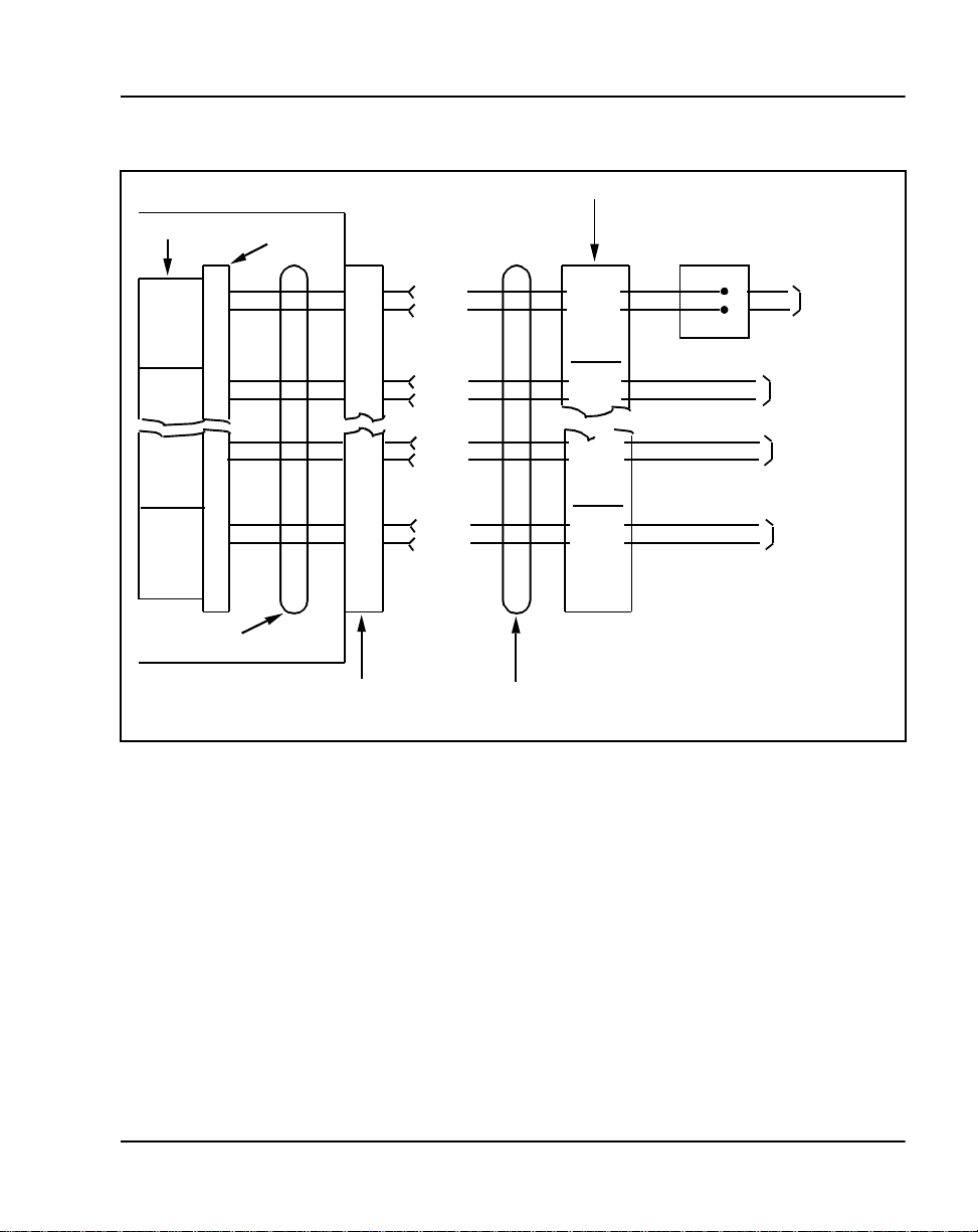
Figure 16
M2317 telephone cross-connections
M2317 Telephone Page 57 of 104
Line Pac k
Unit 0
Unit 1
Unit 6
Unit 7
Part of Shelf
Wiring Harness
PE Shelf
Pack Co nnector
T0
R0
T1
R1
T6
R6
T7
R7
26
1
28
3
38
13
40
16
Shelf Connector
(W-BL)
(BL-W)
(W-G)
(G-W)
(BK-G)
(G-BK)
(BK-S)
(S-BK)
Part of multi-pair Cable
Cross-connect Block
T0
R0
T1
R1
T6
R6
T7
R7
TELADAPT
Connecting Block
G
R
Tip
Ring
553-1291
Line Cord
to Telephone
To Telephone
To Telephone
To Telephone
Meridian 1 Telepho nes Description and Specifications
Page 58

Page 58 of 104 M2317 Telephone
Ordering information
This section provide s ordering information for the M2317 telep hone. Refer to
the Nortel Networks pri ce book or contact your Nortel Networks
representative for specific ordering codes.
If the M2317 telephone fails to function properly, or if mechan ical breakage
occurs, do not attempt to make repairs in the field. Return the unit to the
manufacturer.
Note: The NT1F09AA Synchronous Dat a Option must be release 4 or
higher and requires the use of the multi-output Data Power Supp ly
(A0336823).
553-3001-108 Standard 9.00 April 2000
Page 59

72
Page 59 of 104
M2616CT (Cordless Telephone)
Content list
The following ar e th e topics in th i s section:
• Functional description 60
• Physical characteristics 60
• General features 62
• Firmware features 66
• System Software 66
• Modu lar Op ti ons 66
• Call Center 67
• System Administration 67
• M2616CT (Cordless Telephone) Battery 67
• Handset Registration to Base Unit 67
• Wall mounting the M2616CT 67
• Specificat ions 67
• Safety considerations 67
• Power requirements 68
• Environmental considerations 69
• Line engineering 71
• Ordering information 71
Meridian 1 Telepho nes Description and Speci fications
Page 60

Page 60 of 104 M2616CT (Cordless Telephone)
Reference list
The following are the references in this section:
• Digital Telepho ne Line Engineering (553-2201-180)
• X11 Administration (553-3001-311)
• M2616CT Cordless Telephone User Guide
This chapter provides feature and sp ecification information for the Meridian
M2616CT cordless telephone.
Functional description
This section introduces the M2616CT (cordless telephone). The M2616CT
provides the user with mobility within the office environment. The M2616CT
is an unlicens ed 900 MHz single cell narrowband digital telephone. It
supports 20 users within a maximum area of 50,000 square feet. The
maximum range of the M2616CT from bas e to the register handset is 150
feet, depending on the phone’s location. The following information is an
overview of the bas e and handset units.
Physical char ac ter is tic s
Keys
The M2616CT Cordles s telephone is equ ipped with 17 feature keys which are
arranged as follows:
Fixed keys
The fully integrated M2616CT base unit provides 13 programmable
line/feature keys, plus a dedicated handset Locator, Volume control, Hold,
Release, and Hands free Mute and Program key. The handset has 6
programmable keys that c orresp onds to t he 6 keys on the ba se unit (3 bo tt om
keys on each side of the LED indicator).
There are six keys to which a fixed function is assigned. They consist of the
following:
• 1 Releas e k ey
•1 Hold key
• 1 Volume control key (with 2 toggle positions)
553-3001-108 Standard 9.00 April 2000
Page 61

M2616CT (Cordless Telephone) Page 61 of 104
• 1 Program Key
• 1 Handsfree/Mute key (with associated LCD indicator)
•1 Locator key
Volume control key
Volume is controlled by one key with two toggle positions. Operating the
“Volume Up” or “Volume Down” pa d of the key incremental ly increases or
decreases the volume for the tone or sound that is currently active. Note that
to change the volume of the ringing sound, the user must depress “Volume
Up” or “Volume Down” during the inte rval when a burst of ringing is hear d.
The volume settings are retained for subsequent calls until new volume
adjustments are made.
Handsfree key
When Handsfree is on, you can talk to another party without lifting the
handset. Handsfree can be activat ed by pressing the Handsfree/Mute key, or
by pressing a DN ke y without lifting the handset. The Handsfree/Mute L CD
indicator shows the status of the Handsfree. Once Handsfree is activated, it
can be deactivate d by picking up the handse t or by pressing the Relea se (RLS)
key.
The M2616CT provides independent volume adjustm ents for Handsfree,
handset, and alerting tone volumes (on-hook dialing and buzz). For detailed
adjusting information, refer to the M2616CT Cordless Telephone User
Guide.
LCD indicat ors
LCD indicators support the following four ke y/LCD states:
Function LCD state
idle off
active on (steady)
ringing flash (60 Hz)
hold fast flash (120 Hz)
Housing
The housing of the M2616CT Cordless Telephone consis ts of a molded
plastic base and faceplate. There is a display on both the base unit and the
handset unit.
Meridian 1 Telepho nes Description and Specifications
Page 62
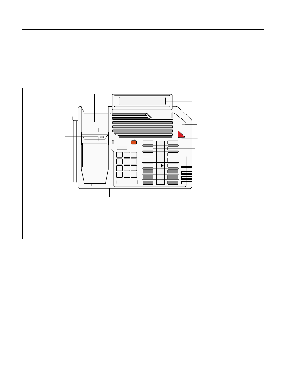
Page 62 of 104 M2616CT (Cordless Telephone)
General features
The figures an d fig ure sho ws the locat ion of ea ch cont rol on your M2616CT
and a brief description of the controls.
Figure 17
M2616CT Base Unit
Spare battery port
Display
Base antenna
Battery contacts
Charge indicators
Hold key
Handset Cradle
Handset Contacts
Meridian
Message Waiting
Indicator
Release key
Locator key (dedicated)
Indicators
Feature and line keys (16)
Gray-filled feature buttons (6)
Microphone
Volume control
553-8565
Base Unit Controls
• The Base Disp l ay
• The Feature an d line ke y s
is a two-lines, 24 characters display.
allows you to access telephone features and
lines. Six fe ature key s map to the h andset fea ture keys. They are the three
bottom keys, on ei ther side of the light indicator LED strip.
• The Handset cradle contacts
indicator li ght indica tes the ba ttery s tatu s of the hands et; gre en indi cate s
the battery is fully charged.
553-3001-108 Standard 9.00 April 2000
charge s th e co rd less hands et . Th e ch a r ge
Page 63

M2616CT (Cordless Telephone) Page 63 of 104
• The Charge in dicator l ights i ndicate the st atus of the handse t bat tery. Re d
indicates the handset is charging, green indicates the battery is fully
charged. The battery contacts, located on the upper half of the handset
cradle, cha rges the optional sp are battery.
• The Diamond indicator light
• The Locator key
, locates the handset/manual R adio Frequency mode (if
appears beside active lines and fe atures.
feature is assigned).
• The Volume bar
• The Microphone
controls the volume of the handset, spe ake r, and ringer .
allows you to have handsfree calli ng. When Handsfree
is on, you can tal k to another p arty without l ifting the ha ndset. Handsfre e
can be activated by pr es s ing the Handsfree/Mute ke y, or by pressing a
DN key without lifting the handset. The Handsfree /Mute LCD ind icato r
shows the stat us of t he Handsfre e. Onc e Handsfre e is acti vated, it c an be
deactivated by picking up the handset or by pre ssing the Release (RLS)
key.
• The Release key
• The Message Waiting indicator light
terminates an active calls
indicat e that a voice mail message
has been left for you.
Meridian 1 Telepho nes Description and Specifications
Page 64
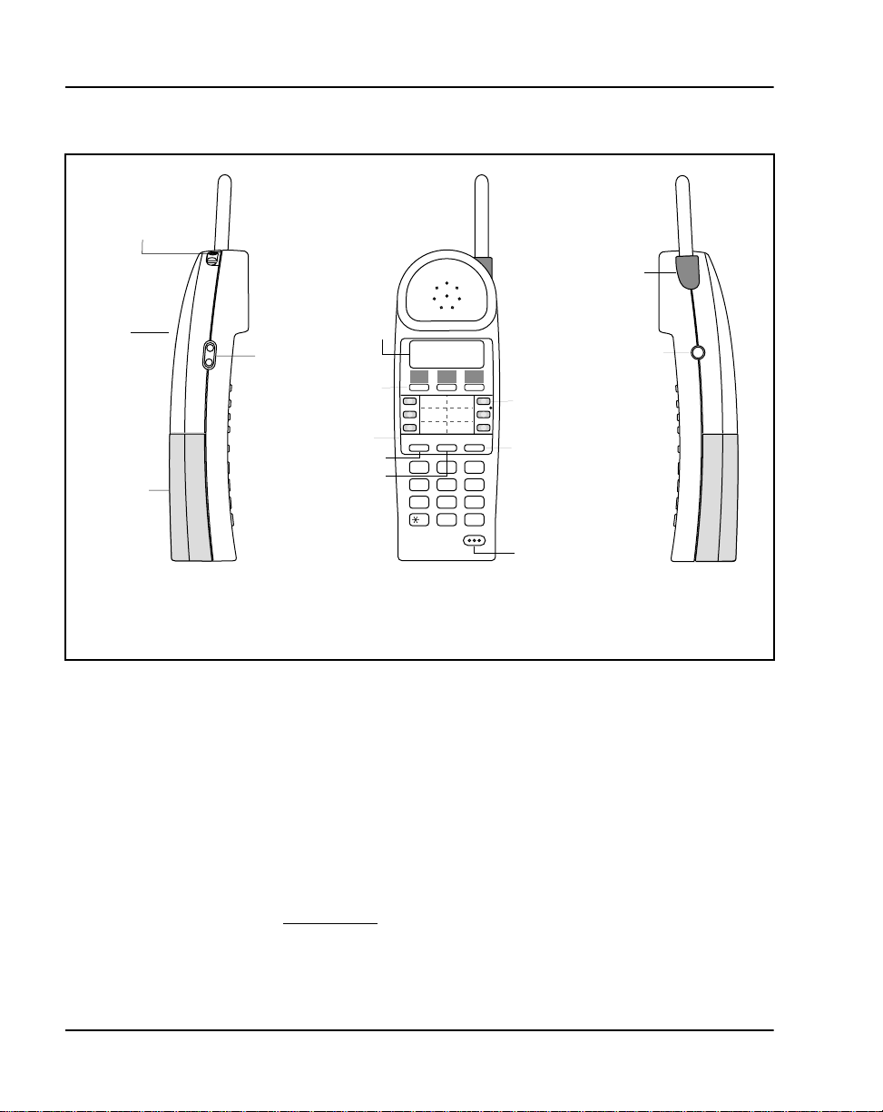
Page 64 of 104 M2616CT (Cordless Telephone)
Figure 18
M2616CT Handset
Headset jack
LED alerter
Speaker
Main battery
Display
Volume control
Display keys
Handset label/
Removable lens
Release key
Scroll key
Rls HoldScroll
DEF
ABC
1 2 3
GHI JKL MNO
4 5 6
PQRS TUV WXYZ
7 8 9
0
#
Single-feature
and line keys
Hold key
Microphone
Options key
553-8569
Handset Controls
• The handset Display is a two-line, 16 character display with a scroll
button located between the Hold and th e Release keys. The scroll key
provides the extra 8 characters that map to the two-line, 24 character
display on the base unit. An arrow on the display indicates when to use
the scroll key to dis play addi tional te xt not shown o n the di splay windo w.
• The M2616CT also displays ic on indicator when the user is out of range
or when the batt er y is low. The Disp lay shows the time , date, call
information and guides you while using the M2616C T features.
• The Display ke ys
upon the state the hands et is in. The prompts are displayed above each
key. The lower line of the display is used to display instructions.
553-3001-108 Standard 9.00 April 2000
shows the prompts and Option list settings depending
Page 65

M2616CT (Cordless Telephone) Page 65 of 104
• The Message Waiting/Ringing Indication is a red LED located on the
base of the handset antenna providing message wa iting indicati on as well
as flashing visual ringing indication.
• The Hand s e t labels
•The Headset jack
allows you to personal ize the feature keys.
connects the det acha ble headset unit . Chec k with your
Nortel Networks representative for authorized headset vend ors.
•The Hold key
The Options key
places an active call on hold.
changes the M2616CT settings in the Option lis t.The
Option key, located on the right side of the;M2616CT handset, in
conjunction with three display function keys empower users to
customize handset options, including:
— Spe ak er on/off - One-way receive speaker al lo ws users to
conveniently listen to voice mail or listen on a conference without
holding the handset to their ear.
— Mute - Microphone mute selection
— Ring Selection - allows users to select or change the ringing cycle
or
— Vibrate mode - vibrati ng noti ficat ion inste ad of usual ri ngi ng cycle .
You must purchase a nd inst all a spe cial vibra ting ba ttery i n orde r to
use this feature. Contact your local Nortel Networks distributor for
the part number.
— Backlight (on/off) - lights the display when the handset is in use
— Base Lock/Unlock - allows the user to lock the M2616CT base unit
to prevent othe rs fro m acce ssing t he base whi le the h andse t is in us e.
— Ring Volu me - ad justs the handset r eceive volume
— Current Audio - resets the handset volu me to the default setting
— Move Call Opti on - allows the user to conveniently move from a
handsfree ca ll on the base unit to the han dset or move and call from
the handset to handsfree on the base unit.
• The Release key
• The removable lens
terminates an active call.
protects the ha nd s et label s .
Meridian 1 Telepho nes Description and Specifications
Page 66

Page 66 of 104 M2616CT (Cordless Telephone)
• The Single-feature and line keys allows one-touch dia ling, feature
operation or line ac cess. These 6 keys corresponds to s ix of the
single-feature keys on the base. The singl e-feature keys glow red to
indicate when lines or features are active.
• The Scroll key
• The Volume control
• The LED alerter
indicator.
• The Speaker
handset.
• The Handset automatically goes into Sleep Mode
idle for more than 45 seconds. The handset can be “awakened” by
pressing a DN key, or the dis play key associated with the “Wake ”
function on the display.
Firmware features
The M2616CT utilizes the Digital Line Card, NT8D01xx for Meridian 1
Option 11 t hrough 81C and MS L-100, an d the Opt ion 11C Co mpact Mi ni IPE
24 Port Digital Line Card, NTMW05AA.
System Software
The M2616CT is compatible with the following systems:
• Meridian 1 Option 11 through 81C running X11 Release 14 and higher
software
• Option 11C Compact running X27 and higher software
displays additional information in the display window.
adjusts the volume on ring and alerter tones .
provides visual ringing indicator and message waiting
allows you to listen to voicemail without holding the
when the hand set is
Modular Options
The following modula r options are not support ed on the M2616CT due to
required placement of the RF circuitry within the telephone:
• Meridian Communications Adapter (MCA)
• Analog Terminal Adapter (ATA)
• Key Expansion Module(s)
• External Alerter Interf ace
553-3001-108 Standard 9.00 April 2000
Page 67

M2616CT (Cordless Telephone) Page 67 of 104
Call Center
The Meridian M2616CT doe s not support ACD features, and therefore,
should not be programmed as a Call Center agent or supervisor.
System Administ ra tion
To configure the M2616CT (Meridian Digital Cord less) set on the Meridian
1 system, refer to X 11 Adm i nist rat ion (553-3001-311), LD11.
For the Locator key (key 14) to function, do not assign a feature to this key.
Handsfree is required for the M2616CT to function properly.
M2616CT (Cordless Telephone) Battery
The M2616CT handset uses rechargeable 700 mAh and 1000 mAh
Nickel-Cadmium batteries. Use only the bat tery identified or provided with
this produc t. It should be cha rged acc ording to the i nstructi ons and limitatio ns
specified in the M2616CT Cordless Telephone User Guide.
Handset Registration to Base Unit
Each M2616CT h andset is aut omaticall y regist ered t o its respective base unit.
In cases where a substitute handset is require d for troubleshooting purposes,
a different M2616CT handset can be reregistered by placing the handset
on-hook, and unplugging, then re-plugging in the AC power adapter and
telephone li ne c ord.
Wall mounting the M2616CT
The M2616Ct base is equippe d wit h a rever sible footst and tha t allo ws you to
mount the telephone on the wall. F or complete details refer to the M2616CT
Cordless T elephone User Guide.
Specifications
This sectio n lis ts the specifications required for the M2616CT (Cord les s
Telephone).
Safety considerations
The following safety procedures should be followed.
Meridian 1 Telepho nes Description and Specifications
Page 68

Page 68 of 104 M2616CT (Cordless Telephone)
Shock hazards
The telephon e is not intended for direct connection to the public switched
network or other expos ed plant networks, because the exposed pins on the
handset cradle ( where the handset sits) cre ates a possible outle t for harmful
voltage. The M2616CT is designe d to be used with a Meridian PBX. Before
installi ng the M2616CT refer to M2616CT Cordless Telephone User Guide.
Proper installation and charging procedures for the M2616CT battery pack
are required to reduce risk of fire or injury to persons.
If the battery is cra cked or damaged discard the bat tery. A damaged battery
can leak electro l ytes which are toxi c if swallow ed, are corrosive and can
cause da mage to the ey es and skin .
Do not short circuit the battery. Exercise care in handling batteries in order
not to short t he battery with cond ucting mater ials su ch as rings, bracelets , and
keys. The battery or conductor may overheat and cau se burns.
Power requirements
Both the M2616CT telephone and the M2018 telephone are loop powered.
Loop power uses +15 V and –15 V sour ce s and as sumes 3500 f eet maxi mum
loop length of 24 AWG (0.5 mm) wire and a minimum of 13.5 V at the
telephone term inals. The RF deck which power the handset requires a wall
transformer (Class 2 power supply Output rat ed at 7.5vdc).
The M2616CT handset uses rechargeable Nickel-Cadmium batteries. Both
700 mAh and 1000 mAh battery wi th or without vi brate alerter are available.
Battery charge time for the 700 mAh battery takes approximate ly 2.25 hours
when attached to the h andse t and provi des approxim atel y 4 hours contin uous
talk time if the handset backlight is turned on. If the handset backlight is
turned off, up to fi ve hours of co ntinuous talk tome is provide d, dependi ng on
usage. Up to 72 hours standby battery time is provided when the handset is
off of the base unit.
The 1000 mAh battery takes up to 2.5 hours to charge when attached t the
handset and provided approximately 5.5 hours continuous talk time if the
handset backlight is turned on. If the handset backlight is turned off, up to 7
hours of c ontinuou s talk ti me is provided, dependin g on usa ge. Up t o 86 ho urs
standby battery time is provided when the handset is off the base unit.
553-3001-108 Standard 9.00 April 2000
Page 69

M2616CT (Cordless Telephone) Page 69 of 104
The batteri es are charged in both the handset and the base unit . It should be
noted th at the spare battery charging port on the base unit provides a “tric kle
charge” that cha r ges the battery at a slower rat e tha n through the handset.
If the power supply fails , the optional spare battery in the spare batt ery
charger will power the ha ndset (available talk-time depends on how much
charge remains in the batt ery) . The bas e phone c ontinue s to func tio n with out
the handset in handsfree mode even if the power supply fails and the spare
battery is discharged or not available.
Environmental considerations
The following environm ental procedures should be followed.
Environmental Performan ce
Depending on the environm ental condit ions, the range of the M2616C T may
be reduced. Steel girders and concrete walls ca n limit the range of the cordle ss
telephone. Line of site conditions pr ovide a maximum range of 150 feet.
Some microwave towers a nd other products that sent out 900MHz
frequencies can cause clipping when the handset is in use. A manual radio
frequency (R F) ch annel sel ectio n des cribe d below pre vents inte rfer ence with
other 900 MHz devices.
The M2616CT uses 900 MHz narrowband technology to deliver digital RF
signals from the M2616CT base to the handset. Twenty 900 MHz narrow
band channe ls have been a llocated to the handset. When the handset is lifte d
from the base the RF deck in the base scans the 20 channels for a clear channel
to use. RF channels can also be manually s elected using key 14 on the base.
Meridian 1 Telepho nes Description and Specifications
Page 70

Page 70 of 104 M2616CT (Cordless Telephone)
Table 9
M2616CT Frequency Ranges
Channel/ Frequency Channel/ Frequency Channel/ Frequency
CH00 902.6 CH06 912.0 CH13 919.6
CH01 904.0 CH07 914.2 CH14 921.4
CH02 905.6 CH08 914.8 CH15 921.4
CH03 907.2 CH09 915.2 CH16 923.0
CH04 908.8 CH10 915.8 CH17 924.8
CH05 910.6 CH11 916.4 CH18 926.4
CH06 912.0 CH12 918.4 CH19 927.6
CH07 914.2
Range
Up to 20 M2616CT sets can be installed within a coverage area of
approximately 50,000 square feet. The typical range of the M2616CT base
unit to the cordless handset is between 125 feet to 150 feet. In open
environments, additional coverage may be achieved.
If a user steps out of ra nge durin g an act ive ca ll, t he M2616CT simply pl ac es
the call on Hold, giving the user an opportunity to step back into range and
convenientl y res ume the call by pressing the DN (Directory Number) key.
Out-of-range indication on the handset dis play is also provided, whet her the
user is on an active call or when the handset is idle.
Outside Plant
M2616CT is not intended for direct connection to the public switched
network or other outside p lant network s. The inte rface in t he M2616CT i s not
suitable for direc t conne ction to li ne s tha t exit t he buildin g, or conn ectio ns to
non-approved telecommunications products. Exposed contacts at the base of
the M2616CT are directly connected to the line cord. Any foreign voltage
from the line c ord can be expos ed to these contacts wi thout pro per protect ion,
and may cause personal injury.
553-3001-108 Standard 9.00 April 2000
Page 71

M2616CT (Cordless Telephone) Page 71 of 104
Medical Facilities
The M2616CT is a 900MHz radio freq uency telephone that may cause
problems in medi cal facilitie s. Pl ease be advised when using this telephone
and ensure that all safety precautions are followed.
Temperature and humidity
Operating state:
Temperature range 0° to 50° C (32° to 122°F)
0° to 40° C (32° to 104°F) with Data Op tion
Relative humidity 5% to 95% from 4° to 29°C (39° to 84° F)
noncondensing
5% to 34% from 29.5° to 49°C (85° to 120°F)
noncondensing
Storage:
Temperature range –20° to 70° C (–4° to 158° F)
Relative humidity 5% to 95% from –20° to 29°C (–4° to 84°F)
noncondens ing
5% to 15% from 29.5°C to 66°C (85° to 150°F)
Battery Disposal
Rechargeab le Nickel -Cadmium ba tteries a re rec yclable and must be disposed
of or recycled properly.
• Discard the battery according to local ordinances.
• Do not discard the battery in office or household waste.
• Do not incinerate the battery, it may explode.
Line engineering
M2616CT telephones operate through twist ed pair wiring on transmission
lines selec ted by the rules given in Digital Telephone Line Engineering
(553-2201-180). The maximum permissible loop length is 3500 ft. of
24 AWG (0.5 mm) standard twisted wire with no bridge taps.
Ordering information
This sectio n provides ordering inform ation for the M2616CT (Cordless
Telephone). Refer to the Nortel Networks pric e book or contact your Nortel
Networks representative for specific ordering codes.
Meridian 1 Telepho nes Description and Specifications
Page 72

Page 72 of 104 M2616CT (Cordless Telephone)
If the M2616CT fails to funct ion prope rly, or i f mecha nical bre akage o ccurs,
do not attempt to make repairs in the field. Return the unit to the
manufacturer.
553-3001-108 Standard 9.00 April 2000
Page 73

74
Page 73 of 104
M3900 Series Meridian Digital Telephones
The M3900 Series Meridi an Digital Telephon es provide versatile
functionality to the desktop environment. The M3900 S eries consist s of five
models:
• M3901 Entry Level Telephone
• M3902 Basic Telephone
• M3903 Enhanced Telephone
• M3904 Professional Telephone
• M3905 Call Center Telephone
For more information on th e M3900 Series Meridian Digi tal Telephones refer
to M3900 Series Meridian Dig ital Telepho nes: Descript ion, Instal lation, and
Administration (553-3001-216).
Meridian 1 Telepho nes Description and Speci fications
Page 74

Page 74 of 104 M3900 Series Meridian Digital Telephon es
553-3001-108 Standard 9.00 April 2000
Page 75

84
Page 75 of 104
i2004 Internet Telephone
Content list
This section explains the following topics:
• Reference list 75
• General features 76
• Physical characteristics 79
• Firmware features 82
• Software requirements 82
• Specificat ions 83
• Power and regulatory specifications 83
• Temperature and humidity specifications 83
• Power requirements 83
Reference list
This section refers to the Meridi an Internet Telephony Gateway (ITG) Line
2.0/i2004 Internet Telephone Description, Installation, and Operation
(553-3001-204)
Functional description
This sectio n describe s the featur es, ke ys, options , soft ware requ irements and
more functional de tails that describe the i2004.
Meridian 1 Telepho nes Description and Speci fications
Page 76
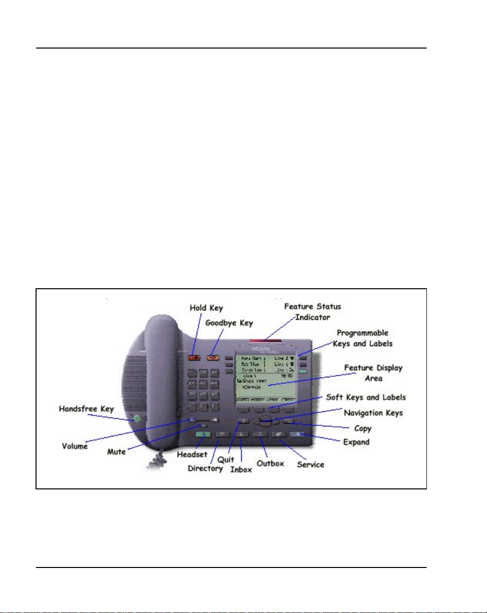
Page 76 of 104 i2004 Internet Telephone
General features
The i2004 supports most of the combination features and DN types that are
supported on the M2616 telephone, except for Distinctive Ringing an d
DN-Based Message Waiting features (see “M2000 Series Meridian Digital
Telephones” on page 11). The total number of features and DNs for any
specific i2004 Internet Telephone cannot exceed six assigned to the
programmable keys , plus th e ten predef ined features a ssigned to t he softke ys.
The Meridian 1 downloads the soft key labels. Any changes made in the
Meridian 1 configuration are reflected immediately in the key labeling. DN
keys are labeled with the DN number without the ESN location code.
The i2004 Internet Telephone supports feat ures through Fixed
Feature/Serv ice keys and self- labeled Program mable Line/Feature keys.
Figure 19 identifies the i2004 Internet Telephone Fixed Fea ture/Service and
soft keys.
Figure 19
i2004 Internet Telephone
553-3001-108 Standard 9.00 April 2000
Page 77
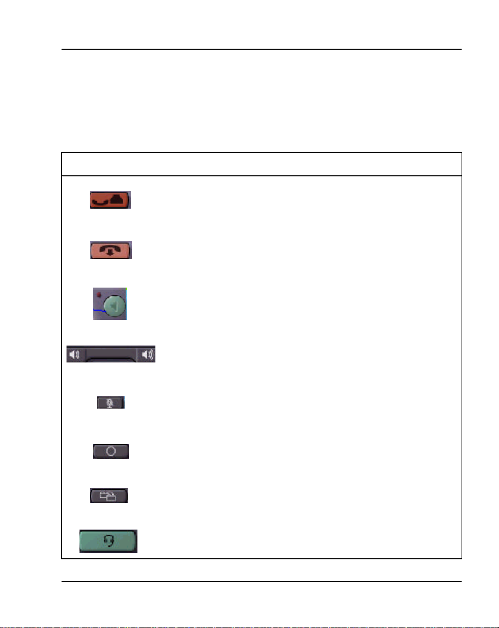
i2004 Internet Telephone Page 77 of 104
Fixed Feature/Service key description
The fixed feature/s ervice keys are permanently labeled keys that provide
quick access to commonly used features. Table1 describes the Fixed Key
icons .
Table 1
i2004 Internet Telephone fixed key icon description (Part 1 of 2)
Icon Label Description
The Hold key allows the user to place a call on Hold.
The Goodbye Key all ows the user to disconnect any type of call .
Handsfree button with LED and enhanced audio speaker
Volume Up/Down control.
Handset, headset (receive, transmit),
handsfree, ringer and buzzer volume adjustments are supported
by the i2004 volume up/down control.
Mute key with LED
Quit key - Used to exit displayed options or services
Copy key
Headset key - reserved for future use. An audible non-working tone is
generated and the LCD displays "Se rvice not available".
Meridian 1 Telepho nes Description and Specifications
Page 78
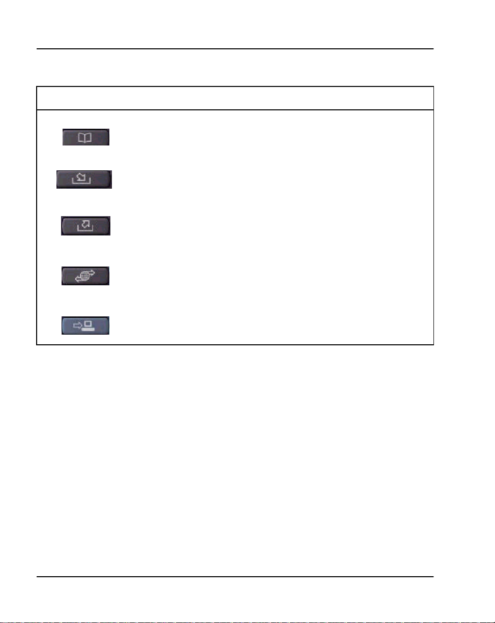
Page 78 of 104 i2004 Internet Telephone
Table 1
i2004 Internet Telephone fixed key icon description (Part 2 of 2)
Icon Label Description
Directory ke y - reserved for future use. An audible non-working tone is
generated and the LCD displays "Se rvice not available".
Inbox key - reserved for future use. An audible non-wo rkin g tone is
generated and the LCD displays "Se rvice not available".
Outbox key - reserved for future use. An audible non-working tone is
generated and the LCD displays "Se rvice not available".
Services key - provides an options li st for basic telephone control s.
Expand ke y - r eserved for futur e use. An audible non-working tone is
generated and the LCD displays "Se rvice not available".
Other i2004 features include:
• 12-Key keypad
• Handset
• four Navigation keys: left, right, up, down
• six programmable DN or feature keys
• four soft-labeled keys
• one 5 x 24 display (1 info line, 3 text lines, and 1 label line)
• Message Waiting Indicator lamp
553-3001-108 Standard 9.00 April 2000
Page 79

i2004 Internet Telephone Page 79 of 104
Message Waiting Indicator (MWI)/Alerting LED
The Message Waiting Indic ator (MWI) is a dual-purpose LED that inform s
the user of new voice messages. The LED on indicates a new message . and
it’s used during al erting to visually inform the user that the i2004 is ringing
(LED flashes during alerting).
The LED fla sh es for a n in com ing ca ll wi th n o ac tive c al ls ( i.e . - s et id le or al l
calls on hold, regardless o f messa ge waiti ng state .)
The LED is solid for new messages present and no incoming calls.
i2004 Options
The options functions control user-spec ific i2004 Internet Telephone
operating param eters. If the Meridi an 1 initializ es, the ITG Line 2.0 card fail s
or the i2004 Internet Telephone goes through a power-up cycle, the options
settings are lost and the i2004 reverts to the default values.
• Volume adjustment
• Language
• Ring Type
• Contrast adjustment
• Display diagnostics
• Key Click
• Time and Date Format
•Call Timer
• Predial recall
Physical charac ter is tic s
This section describes the i2004 Internet Telephone physical characteristics.
Meridian 1 Telepho nes Description and Specifications
Page 80
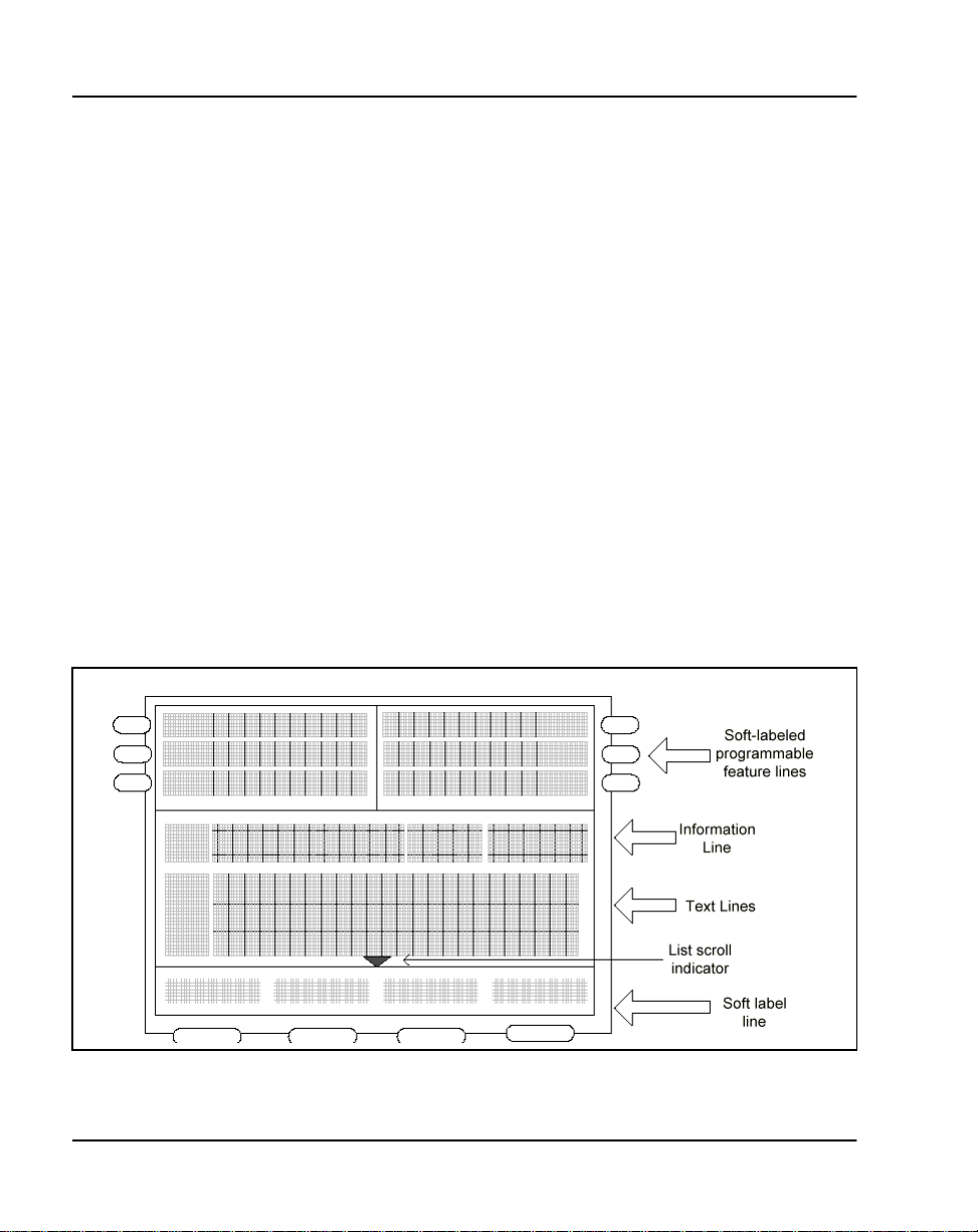
Page 80 of 104 i2004 Internet Telephone
Housing
The housing of the i2004 Internet Telephone housing consists of a molded
plastic foots tand and the faceplate. The bottom of the housing provides
manufacturing part number and model number information, a power supply
connection, an RJ45 Ethernet port, a handset jack and a headset jack. There
is also space to write a MAC address, which is a form of IP ad dress.
i2004 display screen and softkeys
The i2004 Internet Telephone has a Liquid Crystal Display (LCD) screen
(see Table 20). The i2004 has six soft-label keys, three on either side of the
LCD. The banner line is the top line of the main part of the display. This fiel d
is logically s plit into four text fi elds , from le ft to right ; a Numeric inde x field
allowing three characters, a context field allowing 12 characters, a date field
allowing five ch aracters , and a time field al lowing up to s ix chara cters plu s a
colon. The status bar/alphanumeric information area accomm odates up to
three lines of text and associated free-format status icons. The sof tkey labels
are four fie lds of s even char acter s each. If the lis t sc roll in dic ator i s turn ed on
(dark), use the navigation up/down arrows to ac cess additional data not
shown in the list.
Figure 20
i2004 LCD display screen
553-3001-108 Standard 9.00 April 2000
Page 81

i2004 Internet Telephone Page 81 of 104
y
Soft-labeled programmable feature keys
The six soft-labeled programmable feature keys (and de dicated icon) can be
assigned with either fe atures or DN’s. The DN keys wil l be labeled wi th the
appropriate digits to reflect that DN.
Soft keys
The four soft keys are dual-purpose keys. In idle or call-in-progress mode,
these keys function similar to the soft-labeled programmable feature keys.
Key functionality is defined by the Meridian 1 using the Key Map Download
X11 message. Each key can be assigned with any features defined in
Appendix B. T he la bel s ass ociat ed with the se sof tke ys rem ain b la nk until the
download messages have been received. If the Meridian 1 assigns more than
four functions to thes e softkeys, the i2004 automatically labels the rightmost
softkey as the More… key.
Pressing the Mor e. .. key give s t he user acc ess t o ot her fu nctions not c urrently
shown in the softkey ar ea. Feature labels assoc iated with these keys can use
up to seven characters to identify that feature. If the i2004 is executing an
application (either local or server based), then these softkeys are controlled
by that a ppli cati on. Upon c ompletion of th e appl icat ion, the i 2004 ret urns the
function (and corresponding labels ) of each soft key to those previously
specified by the Meridian 1.
Handset, headset key, handsfree operation summar
The headset and the Handsf ree inter faces are controlled by h ar d keys. The
handset operation is typical. Headset operation is simplified i n that users are
not required to conn ect/disconnect the device before and after ea ch headset
call.
Handsfree is activated by pressi ng the Handsfree hardkey. In addition, if the
i2004 is set to defa ult the voice pa th to the handset, pre ssing a line key without
lifting the handset will result in dialtone in the Handsfree mode.
While on a call, the user can change the voice path by pressing the appropriate
hardkey (headset /Handsfree) or by pickin g up the ha ndset.
Meridian 1 Telepho nes Description and Specifications
Page 82

Page 82 of 104 i2004 Internet Telephone
Mute key operation
Pressing the Mute button causes the set to toggle between muted and
unmuted. When in t he mut ed s t at e th e LED a dja ce nt to t he Mut e b utt on is l it .
When in the m uted state all audi o input, handset, headset , handsfr ee, is mut ed.
Firmware features
The Meridian 1 downloads the set firmware to the i20 04. Table 2 lists the
data features supported by the i2004 firmware.
Software requirements
The i2004 Internet Telephone is available on X11 release 25 and later
software.
Table 2
i2004 data features
Data features i2004
Ring Again X
Speed Call X
System Speed Call X
Call Forward X
Call Tra n s fer
Autodial X
553-3001-108 Standard 9.00 April 2000
Page 83

Specifications
This section lists the i2004 Internet Telephone specifications.
Power and regulatory specifications
The i2004 Internet Telephone must use only the Nortel Networks
recommended, approved Limited Power Source, output rated: 16 Vac,
500 mA, 50/60 Hz.
The i2004 Interne t Telephone is a Class A device that meets FCC Part 15 an d
Canadian ICES-003 specifications.
Temperature and humidity specifications
Operating state:
Temperature range 0° to 50° C (32° to 104°F)
Relative humidity 5% to 95% (noncondensing). At temperatures
Storage:
Temperature range –50° to 70° C (–58° to 158° F)
Relative humidity
i2004 Internet Telephone Page 83 of 104
above 34°C (93°F) relative humidity limited to
53 mbar of water vapor pressure.
5% to 95% (noncondensing). At temperatures
above 34°C (93°F) relative humidity limited to 53
mbar of water vapor pressure.
Power requirements
The i2004 Internet Telephone is powered by a 16 Vac, 500 mA wall
transformer t hat shi ps wi th the i 2004 Interne t Telephone bo xed pa ckage. The
transformer connects to the i2004 through a “barrel” connector that is
installed in a port in the bottom of the i2004 Internet Telephone. There is no
provision for closet powering through the RJ45 Ethernet connector.
Meridian 1 Telepho nes Description and Specifications
Page 84

Page 84 of 104 i2004 Internet Telephone
553-3001-108 Standard 9.00 April 2000
Page 85

98
Page 85 of 104
Data options
Content list
The following ar e th e topics in th i s section:
• Reference list 85
• Asynchronous Data Option (ADO) 86
• Functional description 86
• Meridian Communications Adapter (MCA) 91
• Functional description 91
• Meridian Communications Unit 96
Reference list
• Functional description 96
• Analog Terminal Adapter 97
• Functional description 97
The following are the references in this section:
• Meridian Communications Unit and Meridian Communic ations
Adapter: Description, Installation, Administration, Operation
(553-2731-109)
• Transparent Data Networking (553-2731-110)
• X11 Administration (553-3001-311)
• Asynchronous Data User Guide
• Analog Terminal Adapter Quick Referenc e Car d
Meridian 1 Telepho nes Description and Speci fications
Page 86

Page 86 of 104 Data options
• Meridian Communications Adapter User Guide
• M2317 Quick Reference Car d
This chapter describes the Meridi an Communications Adapter (MCA), the
Meridian Programmable Data Adapter (MPDA), the Asynchronous Data
Option (ADO), the Meridian Communication Unit (MCU), and the Analog
Terminal Adapter (ATA). This chapter also describes several software
features.
Asynchronous Data Option (ADO)
The M2317 can be equipped with an Asynchronous Data Option (ADO) to
allow you to make a data call us ing keyboard dialing from your attached
terminal or personal computer. Voice and data communications can be
conducted simultaneously wit hout causing any mutual interference.
Funct ional description
The ADO mounts within the telephone and works in conjunction with the
Digital Interface Chip to provide asyn chronous communication up to
19.2 kbps from an ASCII data termi nal or a personal computer to the
Meridian 1 Integrated Services Network. The ADO appears as Data
Circuit-terminating Equipment (DCE) in your terminal and conne cts to the
Data Terminal Equipment (DTE) through an RS-232-C connector mounted
on the ADO printed circuit board.
553-3001-108 Standard 9.00 April 2000
Page 87

Data options Page 87 of 104
The Asynchronous Data Opt ion supports:
• Hayes dialing
• Automatic data rate detection at all rat es up to 19.2 kbps
• ASCII keyboard diali ng (orig inati ng data call s to loca l and remote hosts
or DTE by using the terminal keyboard)
• Cal l or i g inatio n to local and remote hosts
• Call termina ti on
• Ring Again Capability
• Auto Dial
•Speed Call
• Automatic or Manual ans wering of incoming data call s
• Manual Modem pooling
• Remote loopback
• Break detection and generation
Meridian 1 Telepho nes Description and Speci fications
Page 88

Page 88 of 104 Data options
ADO operating parameters
Table 10 shows the operating parameters ADO requires.
Table 10
ADO operating parameters
Data type ASCII
Synchronization Asynchronous, Start-Stop
Number of bits 8 bits
Parity none (unchecked)
Data rate 300, 1200, 2400, 4800,
Stop bits 2 bits for 110 bits per second;
Transmission Full duplex
The ADO supports asynchronous ASCII operation. A data byte is received
from your terminal or personal computer , a control byt e is added, and t he two
bytes are transfer red to the associated line card. In the other direction, two
data bytes are received from the line card, the contr ol byt e is delet ed, and the
data byte i s delivered to your terminal in a bit serial format, at the terminal’s
bit rate.
9600, 19200 bits per second (autobaud)
1 bit for all other speeds
ADO external power supply
The ADO requires an extern al power suppl y in add ition to t he power from the
line (see Table 11). A 110 V ac 60 Hz, 100 V ac 50/60 Hz, or a 220 V ac 50
Hz multi-output power supply unit provides nominal voltages of +5 V,
+12 V, and –12 V dc. The power supply c onnects to the back of the tel ephone
through a 5-pin Molex power connector.
If the AC power supply fails , da ta calls cannot be processed. All external
power supplies are equipped with short circuit and thermal shutdown
protection.
553-3001-108 Standard 9.00 April 2000
Page 89

Data options Page 89 of 104
Table 11 lists the input and output requirement s for the ADO exte rnal power
supply.
Table 11
I/O requirements for ADO external power supply
North American version
NPS50220-03L5 Multi-output exter nal power supply
(A0336823), UL list ed and CSA approved
Input: 57–63 Hz 115–132 V ac
Output: +5 V dc, 1.0 A (pin 3 for supply, pin 2 for return)
+12 V dc, 200 mA (pin 6 for supply, pin 1 for return)
–12 V dc, 200 mA (pin 4 for supply, pin 1 for return)
Japanese version
NPS50220-03L8 Multi-output exter nal power supply
(A0336891), Japan Standard (“T” Mark)
Input: 47–63 Hz 85–115 V ac
Output: +5 V dc, 1.0 A (pin 3 for supply, pin 2 for return)
+12 V dc, 200 mA (pin 6 for supply, pin 1 for return)
–12 V dc, 200 mA (pin 4 for supply, pin 1 for return)
European version
NPS50220-03L5 Multi-output exter nal power supply
(A0336166), conforming to NPS50561 general
requirements and UL1012
Input: 57–63 Hz 200–240 V ac
Output: +5 V dc, 1.0 A (pin 3 for supply, pin 2 for return)
+12 V dc, 200 mA (pin 6 for supply, pin 1 for return)
–12 V dc, 200 mA (pin 4 for supply, pin 1 for return)
Meridian 1 Telepho nes Description and Speci fications
Page 90
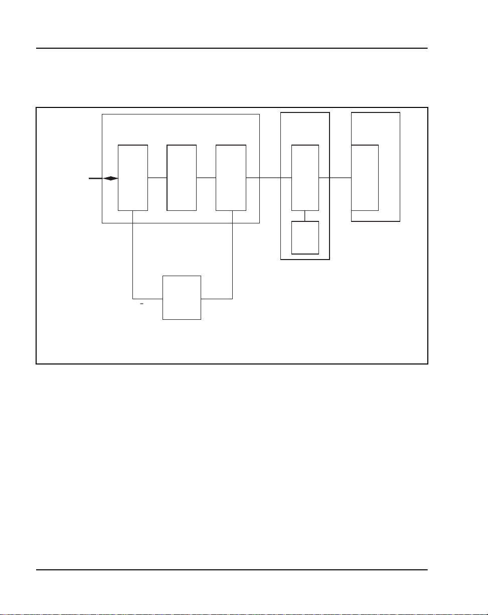
Page 90 of 104 Data options
Figure 21 shows a block diagram of the ADO and M2317 telephone.
Figure 21
Block diagram of ADO and M2317 telephone
RS-232
Data Communications Option
EIA
Drivers
Receivers
+12 V
Commercial A.C. Power Supply Available
for 110V ac 60 Hz, 100V ac 50/60 Hz, or
220 V ac 50 Hz.
12 V
Isolation
External
Power
Supply
+5 V
Micro
Processor
M2000
Telephone
DSIC
CODEC
Meridian SL-1
ISDLC
QPC578
553-3214
See the Asynchronous Data User Guide and t h e M2317 Quick Reference
Card, for more information on ADO operation.
553-3001-108 Standard 9.00 April 2000
Page 91

Data options Page 91 of 104
Meridian Communications Adapter (MCA)
The Meridian Communications Adapter (MCA) replaced the Meridian
Programmable Data Adapter (MPDA) with X11 release 18 and offers
enhanced capabi lity over the MPDA. An MCA can be configured as an
MPDA for use with releases earlier than release 18 .
Funct ional description
The MCA mounts within the telephone (see Figur e 3) and allows
synchronous and asynchronous ASCII terminals, and personal computers to
be connected to the telephone using an RS-232-C or V.35 interface on a
DB-25 connector. With release 14 and later, the MCA allows synchronous
applicati ons (DTEs such as video co nferenc ing equip ment a nd Group IV fax
units) to be connected to the telephone.
Releases 14 through 17 allow access to data functions throug h the keypad
only. However, relea se 18 and later allow access to data functions via bot h
the keypad and service change in LD 11.
Asynchronous mode features supported by the MCA include the following:
• Asynchronous trans mission at up to 19.2 kbps (autobaud)
• Enhanced Hayes commands, including upper- and lower-case dialing,
voice call or iginat io n through AT di aling, hang-up da ta call, and on-li ne
disconnect of voice call
• Script file capability that allows the MCA to learn a dial-up and log on
sequence that can be played back to automatically access a host or
service
• Voice Call Origination ( V C O)
• DCE mode
• Autodial
• Ring Again
•Speed Call
• Autobaud and Autoparity Detect
• Modem Pool Calling
• Host/Terminal Mode
Meridian 1 Telepho nes Description and Speci fications
Page 92

Page 92 of 104 Data options
• Forced Data Terminal Ready (DTR)
• Dynamic Carrier Detect (DCD)
• Inactivity Time-out
• Remote Loopback
• RTS/CTS hardwar e flow co ntro l capabil it y (when ca lling ano ther MCA)
Synchronous mode features supported by the MCA include the following:
• Half Duplex/Full Duplex
• Internal and external clocking
• Modem and network capability
• Synchronous transmission up to 64 kbps
• Public Switched Data Services compatibility. MCA extends PSDS and
64K restricted and 64K clear capabilities to Modular telephones .
• V.25 bis dialing protocol support at all synchronous speeds up to 64
kbps. High-Level Data Link Control (HDLC) and Bisynch (character
oriented) framing of the V.25 commands is supported.
• Programmable e cho can cell er disabl ing f or 56 and 64 kbps network calls
Synchronous and asynchronous mode features supported by the MCA
include the following:
• T-Link and DM-DM support
• T-Link and DM-DM are Nortel Networks proprietary protocols. The
SL-100 and DMS data devices us e T-Link. DM-DM is used by Meridian
1 data devices such as ASIM, AIM, ADM, SADM, Asynchro nous Data
Option (ADO), and MPDA. MCA can use both DM-DM and T-Link.
• Hotline
• Virtual Leased Line
• V.35 interface capability selectab le with jumper plugs on the MCA
553-3001-108 Standard 9.00 April 2000
Page 93

Data options Page 93 of 104
• Data ta n d em ca ll s ac ros s tie trunks , pro vi d ed al l s w it ch e s inv ol v ed ar e
Nortel Networks machines
• PSDS tandem data calls across tie trunks are supported with release 18
or later when each tandem node uses an ISDN Primary Rate Interface
(PRI) or Basic Rate Interface (BRI) connection. See Tr ans parent Data
Networking (553-2731-110) for more information.
Note: Internal PSDS calls are not supported.
MCA ope ratin g parameters
The MCA data parameters are stor ed locally altho ugh the configura tion is set
in the Meridian 1 system. Data parameters may not be set in the system before
installi ng the MCA in the telephone. If the pa rameters are set before the
telephone is ins talled, the configuration information will be lost.
Operating para meters are downloaded after the MCA is enabled in LD 11.
With release 18 and later, system parameters are downloaded when the MCA
is configured in LD 11, and power is reset. (See the X11 Administrat ion
(553-3001-311) for prompt and response details.) Data parameters can also
be set, with rele ase 18 and later software, thro ugh LD 11, as well as by the
keypad.
Meridian 1 Telepho nes Description and Speci fications
Page 94

Page 94 of 104 Data options
The MCA communicates with Data Terminal Equipment (DTE) using the
operating parameters shown in Table 12.
Table 12
MCA operating paramet ers
Synchronization Asynchronous, Start-Stop
Number of bits 8 bits
Parity none (unchecked)
Data rate 110, 150, 300, 1200, 2400, 4800, 9600, 19200
Stop bits 2 bits for 110 bi ts per second;
Transmission Half duplex; full duplex
When installing an MCA or MPDA into NTZK or NT2K phone sets with a
date code pr ior to January 1998, a Power Opt ion board is required, along with
an additiona l power s ource.
bits per second (autobaud) asynchronous
up to 64000 bits per second synchronous
1 bit for all other speeds (asynchronous only)
When installing an MCA in an NT9K or NT2K phone set with date code of
January 1998 or later you will only install the MCA (an additional Power
Option board and Jumper board is not required). See the specifications
section of Chapter 4 for power requirement s inform ation.
Figure 22 shows the back of a Modular telephone with an MCA mounted;
Figure 23 shows a block diagram of the Modular telephone and MCA.
See th e Meridian C ommunications Adapt er User Guide for more info rmation
on MCA operation. See also “Ordering information” on page 39 for MCA
ordering information.
553-3001-108 Standard 9.00 April 2000
Page 95
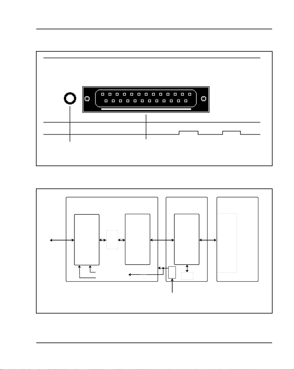
Figure 22
Back of telephone showing MCA
Data options Page 95 of 104
Flashing
LED
RS-232
interface
Figure 23
Block diagram of MCA and Modular tel ephone
Communications adapter
RS-232-C
DTE I/F
EIA
Drivers
Receivers
+12V
Power Supply
-12V
µ
P
MDAD
A64
+5V
+5V
Power supply
option card
Telephone
MTDC
A44
µ
P
I
S
D
L
C
Meridian 1
D
or
L
C
553-1897
553-1854
Meridian 1 Telepho nes Description and Speci fications
Page 96

Page 96 of 104 Data options
Meridian Communications Unit
The Meridian Communications Unit (MCU) was intro duced with
X11 release 19 and provides a stand-alone version of the Meridian
Communications Adapter (MCA).
Funct ional description
The Meridian Communications Unit (MCU) allows you to transmit and
receive data usi ng PSDS ove r eithe r the publ ic network or a pri vate ne twor k.
The MCU, which replaced the QMT21C, is designed for domest ic and
international use, with tra nsmission speeds up to 19.2 kbps asynch and
64 kpbs synch, integrated display, and self diagnostics. The MCU supports
autodialing, ring again, and speed calling, as well as autobauding and
automatic parity detection. You can use the MCU for the following:
• Video conferencing
• LAN bridging
• Bulk data/PC file transfer
• Dial back-up
• Host connectivity
The MCU fully complies wit h RS -232C and can be configured as DCE or
DTE to connect to a terminal, printer, or fax machine.
Unlike the MCA, the MCU provides a dedicated call key and call progress
tones. The MCU also permits smart modem pooling.
The MCU supports the DM-DM, T-Link, V.25 bis , and PSDS interfaces as
well as the RS-232C, CCITT V.35, CCITT V.24, and RS570/RS3449 (with
different cables) inte rfac es. It complies with V.28 for European approval.
Refer to Meridian Communications Unit and Meridian Communications
Adapter: Description, Installation, Administration, Operation
(553-2731-109) for deta iled information on this feature.
553-3001-108 Standard 9.00 April 2000
Page 97

Analog Terminal Adapter
The Analog Terminal Adapter (ATA) allows the use of an off-the-shelf
analog device (FAX, Modem, Telephone) to operate simultane ously with
your Meridian Digital Telephone set. The Analog Terminal Adapter board
fits into the foo ts tand space of your Meridian Digi tal Telephone set.
Funct ional description
The Analog Terminal Adapte r is mount ed in the footstand of your Meridian
Digital Telephone set. The ATA requires a separate AC adapter which
provides a 24 volt AC ext ernal power so urce. The ATA does n ot dr aw power
from your Meridian Digital Telephon e s et.
The Analog Termina l Adapt er (ATA) p rovid es a RJ11 c onne ction for anal og
equipment to operate on the same line as your Meridian Digital Telephone
set. The Analog Terminal Adapter allows you to transmit and re ce ive data
using the publ ic switched telephone network (PSTN). The ATA suppo rts an
analog device li nk to t he desktop or l apt op computer us ers (with modems) in
the digital telephone environment. Currently, it is necessary to install a
separate analog phone line to be able to interface with the PSTN.
You can use the ATA for the following analog devices:
• FAX Machine
Data options Page 97 of 104
•Modem
• Analog Telephone
ATA operating parameters
The ATA data parameters are store d locall y althou gh the configura tion is set
in the Meridian 1 system. Data parameters may not be set in the system before
installing the ATA in the telephone. If the parameters are set before the
telephone is ins talled, the configuration information will be lost.
Simultaneous voice and data capabilities are available with X11 Relea se 22
or later. When the A TA is installed the System Administrator must activate the
Flexible Voice and Data feature by configuring Overlay 11. See the X11
Administration (553-3001-311) for prompt and response details.
The ATA will not provide simultaneous voice and data if the X11 software
release is prior to release 22.
Meridian 1 Telepho nes Description and Speci fications
Page 98

Page 98 of 104 Data options
The Analog Terminal Adapter (ATA) is capable of receiving dial pulse or
DTMF address signaling from the analog equipment .
The ATA uses the 2nd channel of the TCM lo op to add an an alog port to the
digital terminal. It has an RJ11 type jack accessible from the back of the
telset.
The analog interface of the ATA is a 2-wire source, providing A and B leads
(tip and ring) across which analog equipment (modem/fa x) is connected. The
loop length will be >100 fe et. T he analog in ter face of t he ATA is compat ible
with the port types listed in Table 13.
Table 13
Port types compatible with ATA
County Port Type(s)
United
States
Canada ONS Station Interface
ONS Station Interface
Class A OPS Station Interf ace
Class 1300 OPS Station Interface
Defining
Standard(s)
EIA/Tia-464A
FCC Rules Part 68
CAN3-T512.1
CS-03 Part I
Refer to Analog Terminal Adapter Quick Ref er ence Card for detailed
information on this feature.
553-3001-108 Standard 9.00 April 2000
Page 99

100
Page 99 of 104
Glossary
ACD
Automatic Call Distribution
ADO
Asynchronous Data Option
ATA
Analog Terminal Adapter
CCOS
Controlle d Class of Service
CPND
DCE
DLC
DN
DSIC
DTE
Calling Par ty Name Display
Data Communications Equipment
Digital Line Card
Directory Number
Digital Set In t er f a c e C hi p
Data Terminal Equipment
Meridian 1 Telepho nes Description and Speci fications
Page 100

Page 100 of 104 Glossary
EIA
Electroni c Industries Associat ion
FCC
Federal Communications Commiss ion
IDF
Intermediate Distribution Frame
ISDLC
Integ rated Services Digital Line Card
LCD
Liquid Cryst al Dis play
LED
Light Emitting Diode (lamp)
MDF
Main Distribution Frame
MPDA
Meridian Progra mmable Data Adapter
MCA
Meridian Communications Adapter
PCM
Pulse Code Modulation
TN
Terminal Nu mber
553-3001-108 Standard 9.00 April 2000
 Loading...