

Nortel INM 4.1 Planning Manual

Planning Guide PG OC 98-13
Integrated Network Management Products
Integrated Network Management
Broadband Release 4.1
Planning Guide
Document release: Issue 1.2
Date: February 1999
*NTRS10HB.0120*


Integrated Network Management Products
Integrated Network Management
Broadband Release 4.1
Planning Guide
Planning Guide Number: PG OC 98-13
Document status: Issue 1.2
Date: February 1999
1999 Northern Telecom
All rights reserved
Ethernet is a trademark of Xerox Corporation.
HP is a trademark of Hewlett-Packard Co.
NCD is a trademark of Network Computing Devices
S/DMS AccessNode is a trademark of Northern Telecom.
S/DMS TransportNode is a trademark of Northern Telecom.
Tektronix is a trademark of Tektronix Corporation.
UNIX is a registered trademark of UNIX System Laboratories, Inc.
VT100 is a trademark of Digital Equipment Corporation of Maynard, Mass.
X Window System is a trademark of the Massachusetts Institute of Technology.
Planning Guide PG OC 98-13 Issue 1.2

iv of 202
Publication history
February 1999
1.2 (Caroline Samson)
- Official release for INM 4.1 General Availability, updated to include minor
changes.
November 1998
1.1 (Caroline Samson)
- Official release for INM 4.1 General Availability, updated to include
additional information in the INM Broadband Release 4.1 Requirements and
Ordering Information sections.
November 1998
1.0 (Caroline Samson)
- Official release for INM 4.1 General Availability.
Integrated Network Management Broadband Release 4.1 PG OC 98-13 Issue 1.2

Table of Contents
About this document 9
Common Object Request Broker Architecture 10
An Overview 10
Application structure and principles of CORBA 11
Summary of new features 12
Audience 25
Integrated Network Management Broadband Description 27
Migration to CORBA 28
INM Release 4.1 Software Units capabilities 29
Connection Management Building Block 30
Fault Management Building Block 30
Resource Management Building Block 30
Performance Management Building Block 31
Application Management 31
Graphical User Interface and the SONET MOA 31
INM 4.1 New Feature Description 39
New GUI Applications 42
Linear Traffic and Protection Status Display (including 4 Fiber Ring) 42
Protection Control 44
PM Threshold Provisioning 46
Drop and Continue on Protection (DCP) 49
Scalability Enhancements 54
Alarm List GUI Enhancements 56
Snap Grid enhancement 60
Centralized Alarm Printing 61
Trouble Ticketing 63
Contract Interfaces Feature Overview 66
Fault Management Building Block (FMBB) 66
Resource Management Building Block (RMBB) 69
Performance Management Building Block (PMBB) 73
Connection Management Building Block (CMBB) 78
Support for new Network Elements 81
Support for the Passport ATM switch 81
Support for INM NETWORKS switches 81
Support for OC-192 82
Support for the Express CX Release 1.0 and 1.1 and the OC-3 Express Release
3.1 and 4.0 91
Table of Contents v of 202
INM Broadband Release 4.1 PG OC 98-13 Issue 1.2

vi of 202 Table of Contents
Support for the JungleMUX Network element 96
Support for AccessNode and Accessnode Express NE 97
INM Broadband Historical Overview 101
Federated Networks 101
Fault Management 102
High-Speed Traffic Display for OC-12/48 BLSRs 104
Centralized Performance Monitoring 105
Centralized Software Management 107
Centralized Inventory Collection 108
User Interface Enhancements 109
Supported products 111
INM Security Access 113
Customer Network Management 113
Controller, NPC and NE Login Access 113
Additional INM User Support 114
Integrated Network Management Broadband Compatibilities 115
Building Block Compatibilities 144
Bridging 145
INM Broadband Release 4.1 Engineering Considerations 147
INM Engineering Rules 147
INM Engineering Capacities 147
X Terminals Engineering Capacities 152
INM Bandwidth Consumption 152
Bandwidth between Indirect Clients and Indirect Servers 153
Building Block considerations 155
Generic Requirements for CORBA applications 155
CORBA Gateway 156
SONET MOA 157
SONET_MOA_PSC 158
Building Blocks 158
INM Broadband Release 4.1 Requirements 163
Hardware Requirements 163
Hardware restrictions/limitations 166
INM mixed federations limitations note 166
Operating System Requirements 166
Upgrades 168
Installation summary 169
First-time installation 169
Upgrade 170
Workstation setup summary 172
Screen saver 172
Swap space 172
Disk Partition requirements 172
X Terminals 174
Hardware 174
INM Broadband Release 4.1 PG OC 98-13 Issue 1.2

Table of Contents vii of 202
Operating System Parameters 174
Northern Telecom Software Requirements 175
TCP/IP Network Requirements 177
Ethernet 177
TCP/IP 178
LAN requirements 178
X.25 179
WAN requirements 180
Summary 181
Ordering Information 183
INM Broadband Software Ordering 184
INM Broadband Documentation Ordering 187
INM Broadband HP Workstation & X Terminal Ordering 193
List of Terms 195
Appendix 1:
Technical support and information 199
INM Customer Care: How to reach us 199
Critical Issues 199
Product Warranty 200
INM Product Services 200
INM Broadband Release 4.1 PG OC 98-13 Issue 1.2

viii of 202 Table of Contents
INM Broadband Release 4.1 PG OC 98-13 Issue 1.2

About this document
This document describes the Integrated Network Management (INM)
Broadband Release 4.1 application which provides centralized management
across multiple controller subnetworks.INM Broadband Release 4.1 provides
a common network management framework which includes a common
hardwareandsoftwareplatformfor all applications, aGraphical User Interface
(GUI) for day-to-day operations, and open Applications Programming
Interfaces (APIs) to facilitate customization and adaptation for a wide variety
of broadband network elements.
INM Broadband Release 4.1 combines the functionality of the previous Nortel
network management graphical user interfaces provided by the S/DMS
Network Manager or INM Broadband products with the Information
Networking Architecture (INA) Transport product, which provided open
interfaces based on the HP DPE technology.
In INM Broadband Release 4.1, all existing HP DPE APIs are replaced with
CORBA APIs, thereby migrating to a new and open standards based
architecture. Beginning with INM Broadband Release 4.1, CORBA becomes
the technology of choice for distributed network management applications.
9of202
INM Broadband Release 4.1 is the first release of Integrated Network
Management targeted at both the SONET Broadband and ATM marketplaces.
It extendsthe graphical network management functionality offered in previous
releases of Network Manager/INM, and combines it with CORBA APIs to
form one single product offering.
The INM Broadband Release 4.1 product portfolio has the following
characteristics:
• It is a suite of software applications deployed on Hewlett-Packard 700
Series workstations.
• It contains open, standards-based
Architecture (CORBA) interfaces to manage Nortel and non-Nortel
network elements.
• It provides graphical user interfaces for centralized network management.
INM Broadband 4.1 Planning Guide PG OC 98-13 Issue 1.2
Common Object Request Broker

10 of 202 About this document
INM not only provides for surveillance but also provides for provisioning,
performance monitoring, shelf level graphics, protection control, centralized
software management, and inventory collection. INM provides a single point
of operational access for multiple S/DMS TransportNode OC-3/12/48/192
subnetworks, S/DMS AccessNode, SONET Radio, DV-45, TellabsTitan 5500
Digital Cross-Connect systems (DCS), OC-3 Express, JungleMUX, INM
NETWORKS NEs as well as Nortel ATM Passport Network Elements and
potentially other network elements through a graphical consolidated view
which may encompass thousands of widely separated individual Network
Elements (NEs).
Common Object Request Broker Architecture
An Overview
Common Object Request Broker Architecture (CORBA) is a multi-vendor
standard for object-oriented distributed computing. CORBA technology is
based on specifications defined by the Object Management Group (OMG)
which is a consortium of computing involved companies. The OMG is an
international organization of over 600 members, and includes all of the major
vendors of systems and software from around the world, as well as
independent software vendors, large and small consulting companies, and an
increasing number of end user companies.
The OMG only produces specifications and not software. The specifications
are freely available for any company to implement. An implementation of
CORBA is referred to as an ORB (Object Request Broker). There are many
ORBs in the marketplace today, Nortel has chosen Orbix, from Iona
Technologies as its distributedmiddleware CORBA technology to providethe
capabilities to develop distributed applications around its INM Broadband
Release 4.1 product.
Rapidly changing technologies, increased complexity and need for
responsiveness to customer needs have led telecommunication service
providers such as Nortel to explore new andnovel methods for deploying new
telecommunications systems and networks. As a result, the telephony world
has devoted a significant amount of time developing architectures such as
Telecommunications Management Network (TMN).
Concurrent with effortsmade in the telecommunication world, the computing
world has been developing and refining concepts, architectures and platforms
such as OMG CORBA that enable software modules to cooperate and
communicate transparently across different implementations of operating
system, hardware and networks.
Integrated Network Management Broadband Release 4.1 PG OC 98-13 Issue 1.2

Inspired by the technological and architectural advances made, the next
generation of OSSs are rapidly evolving toward highly distributed multivendor systems, with open interfaces, and applications that are independent
from the underlying transport technologies. The fundamental driver for this
migration is the need to develop and deploy highly scalable new services in a
rapid and cost-effective manner.
As such, in order to capitalize on the synergistic aspects of the two
architectures (TMN and CORBA), it is highly desirable to employ CORBA
services in a rapid and cost-effective manner to provide TMN compliant
applications that offer open and standard compliant interfaces.
Application structure and principles of CORBA
Networkmanagement applications aredistributed applications. Inthe CORBA
architecture, which is based on object-orientation methodology, a distributed
application is composed of objects that interact with each other. In general an
object is an abstraction of a resource, concept, or functionality that provides a
set of capabilities for other objects. In practice a CORBA object is more
viewed as a means to model an application entity. More precisely, a CORBA
object is described as “a package of data and code used to implement a
computational construct or to model an application entity”.
About this document 11 of 202
To enable other objects to access its capabilities, a CORBA object offers a
single interface, however the interface may inherit from other interfaces.Each
interface defines a set ofoperations (functioncalls) that can be invokedvia the
interface.
The object that provides the interface is called the object implementation in
CORBA, and the object that invokes operations defined in the interface is
called a client. The terms “Client” and “Server” are used frequently in Corba
to describe the Peer-Peer relationship that exists between the two entities.
Servers contain one or more objects, and are often physically represented as
processes. Objects, not servers are invokable. An object in a server can be
invoked by a client, and this object can use the facilities of other objects in the
system. A CORBA server/executable which groups several CORBA objects
providing services in an application domain may be termed as a “building
block”.
An object’s interface is defined in OMG’s Interface Definition Language
(IDL). IDL is not a programming language. An IDL only defines interfaces,
where each interface definition lists the operations that can be applied to
objects with that interface. In other words, the IDL interface specifies allof the
operationsthe object is going to perform, their input andoutput parameters and
return values, and every exception that may be generated.
INM Broadband 4.1 Planning Guide PG OC 98-13 Issue 1.2
12 of 202 About this document
The IDL interface constitutes a contract with the clients, and is the key to
interworkingacross networks,operating systems and programminglanguages.
In CORBA, programmers tasked with developing client software require
knowledge about the IDL interface definition and the description of what the
object does in order to begin invoking operations on it.
The infrastructure for communication amongst objects in a distributed
environment is provided by middleware as CORBA ORB.
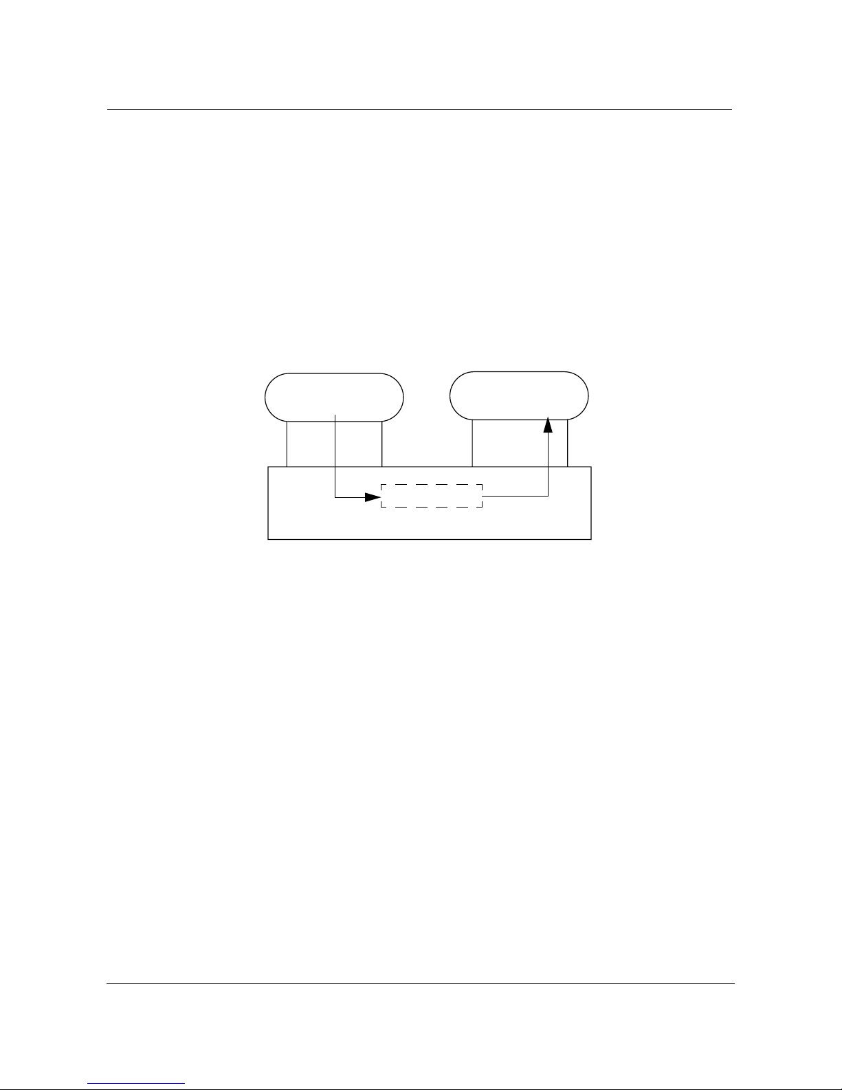
To illustrate the concepts presented in this section Figure 1 on page 12 shows
a simplified overview of a request passing from the client to the object
implementation in the CORBA architecture.
Figure 1. Passing a request from a client to object implementation
CLIENT
IDL
Stub
Request
Object Request Broker (ORB)
OBJECT
IMPLEMENTATION
IDL
Skeleton
The IDL definition completely defines the server interface, but since it is an
abstract language, it does not providethe detailed data structures and function
calls that a programmer must make. To get this information, CORBA also
defines what is known as language mappings. This mapping of IDL to actual
language definitions is done using an IDL compiler.
Putting an IDL through an IDL compiler will generate the required code for
the particular language chosen. For a C++ mapping, the IDL compiler will
output a header file and a client stub. The header file is included in the client
application and the client stub is compiled and linked with the final product.
Summary of new features
The new features offered by the Integrated Network Management Broadband
Release 4.1 applications are summarized below.
• Protection Status and Control GUI and Contract Interfaces (CI) which
provide GUI enhancements to support protection status display and
protection control for OC3/OC12 TBM and OC-48 linear systems (1:1,
1+1, 1:N), 2 fiber-ring systems (OC12 TBMand OC-48BLSR), aswell as
OC-192 4-fiber rings. Protection control will provide the ability to issue
high speed protection control and lockout commands from the Graphical
Integrated Network Management Broadband Release 4.1 PG OC 98-13 Issue 1.2

About this document 13 of 202
NetworkBrowser.This feature will also provide the open, standards-based
Contract Interfaces using the CORBA Interface Definition Language
(IDL) to perform high speed protection switch control on the topologies
mentioned above.
• Linear Systems Traffic Display which provides GUI enhancements to
support the traffic display for OC3/OC12 TBM and OC-48 linear systems
(1:1, 1+1, 1:N).
• OC-48 Release 14.1 support (Connection Management Interface
Enhancements) which provides enhancements to the Connection
Management Building Block (CMBB) Contract Interface (CI) to support
connection provisioning of concatenated STS-3c and STS-12c
bidirectional connections on OC-48 BLSR systems. Enhancements to
termination inventory and information services are also provided in order
to support OC-3 tributary cards on OC-48 Ring (BLSR) systems.
• Drop and Continue on Protection (DCP) GUI and Contract Interface
provides support for the new DCP provisioning scheme to be used when
provisioning unidirectional or bidirectional matched node connections on
OC-12TBM and OC-48 BLSR systems.Enhancements to the GUI support
the selection of either the Drop and Continue on Working (DCW) or the
Drop and Continue on Protection (DCP) provisioning scheme for creating
bidirectional or unidirectional matched node connections. As well, the
editing of an existing unidirectional or bidirectional matched node
connection from the DCW tothe DCP schemeand viceversa is supported.
Enhancements to the Connection Management Building Block (CMBB)
Contract Interface (CI) provide the same DCP provisioning and editing
capabilities through the open, standards based CI using the CORBA
Interface Definition Language (IDL).
• OC3 Express Data Release 3.1 Contract Interfaces Support for Fault
Management, Performance Monitoring, Resource Management. The
supportfor the newEIM card is providedonly through the INM Broadband
GUI.
• OC192 Release 4 GUI and Contract Interfaces Support for Fault
Management, Remote Inventory (including Shelf Level Graphics),
Performance Monitoring and Connection Management (for 4 fiber BLSR
systems).
• Facility Provisioning Contract Interface Enhancements which support
additional attributes and additional facilities. This includes the support for
optical facilities (OC3, OC12, OC48) and electrical facilities (DS1, DS3,
STS1, STS3, STS12 and STS48 on OC3/OC12 TBM and OC48 Network
Elements.
• PM Threshold Provisioning GUI and Contract Interfaces Support where
threshold values for individual PM parameters can be set or queried for
DS1, DS3, STS1 and OCn facilities for OC3 TBM (LTE, linear ADM),
OC12 (LTE, linear ADM, ring ADM, Regen)and OC48 (LTE, ring ADM,
INM Broadband 4.1 Planning Guide PG OC 98-13 Issue 1.2

14 of 202 About this document
Regen) systems. This includes the ability to set up to two threshold values
for each PM on each facility.
• GUI Enhancements will be provided to the Alarm Dialog which will be
enhanced to permit resizing ofthe Dialog itselfas wellas different parts of
it. In addition, new GUI technology will allow the rearranging, removing,
and restoring of columns.
• Web User Interface for OC192 Support provides the user to login to the
OC-192 Network Element (which supports the Web UI) and use the new
Web Based NE User Interface that is being introduced in the
TransportNode OC-192 Release 5.0.
• ResourceManagement Contract Interfaces provide the equivalent support
and functionality existing in the INA Transport Release 2.0 by replacing
the Configuration INADPE Contract Interfaces with the CORBAContract
Interfaces (CI). The CORBA CIs will provide functionality for Network
Element discovery/query, equipment inventory query, as well as Facility
provisioning for OC3/OC12 TBM and OC48 systems.
• Integrated Fault Management provides integrated support for fault
information across multi-domain, multi-vendor networks. The Fault
Management Building Block (FMBB) provides open, standards based
contract interfaces using CORBA IDL supporting alarm query, alarm
notification, alarm count and event notification functionality, as well as
protection status and control.
• ExpressCX GUI Support of Fault Management,Performance Monitoring,
Remote Inventory, Electronic Software Delivery, Remote Login, Shelf
LevelGraphics and ConnectionManagement. Thesupport forthe Express
CXNetwork Element is providedthrough the OC-3 Express MOARelease
3.1.
• PC GUI Remote Login support (JungleMUX JNCI, OC-3 Express, and
AccessNode Express Voice Module) allows an INM Broadband user to
perform a remote login Reach-Through to the PC-GUI application running
on a Windows NT Server machine and running an Element Manager
application.
• AccessNodeExpress Data Module Support for Node Graphics, Shelf Level
Graphics as well as Remote Login.
• Scalability Enhancements for Contract Interfaces extends the engineering
limits introduced in the INM 3.1 to the new Contract Interfaces.
• Centralized Alarm Printing offers the capability to output the alarm
information (severity, reason, network element,...) for the raised and the
cleared alarms: if the Centralized Alarm Printing functionality is enabled,
all raising and all clearing alarms are printed out, in real time, as they
occur.
Integrated Network Management Broadband Release 4.1 PG OC 98-13 Issue 1.2

About this document 15 of 202
• Trouble Ticketing offers the capability to select a fault from the Alarm
Details dialog of the Graphical Network Browser, and generate a
corresponding Trouble Ticket in Clarify’s ClearSupport
TM
product.
These new features offered with the Integrated Network Management
Broadband Release 4.1 build upon the features offeredwith earlier releases to
provide both new and enhanced capabilities.
Features offered with earlier releases of the S/DMS Network Manager/INM
are summarized below.
Fault Management
• Problem Analyzer (PA) performs Intelligent Alarm Filtering (IAF) which
provides the correlation of alarms into direct detect and related alarm
events into a single Network Problem Report. The PA provides additional
information to the user by showing the alarm correlation, viewing
problems not alarms, giving probable cause, providinga NTP reference to
fix the problem, and performing preventive analysis. This feature is
optional and is delivered on a separate CD-ROM/DAT Tape.
• Alarm History and Enhanced Audit Trail for S/DMS OC-3/12/48, and
S/DMS OC-192. The Alarm History Retrieval option provides the ability
to retrieve historical alarm information for the network element from the
graphical user interface. The Enhanced Audit Trail (EAT) provides the
capability to record the alarm information of raised, acknowledged and
cleared alarms.
• NE Alarm Report Suspension offers the ability to suspend and resume
alarm reporting on an Network Element basis, in addition to the existing
alarm control mechanism available for element controllers (spans). These
two functions are complementary in nature and may be used together for
any subset of network elements being monitored by INM.
• External Alarm Control offers the ability to operate external devices and
relays via the serial port on the INM based on incoming alarm information.
Functionality to filter alarms based on element controllers and alarm
severity is provided through this UI enhancement. Alarms passing the
filter will cause simple configurable text strings to be sent to an external
device for post-processing, and as such special hardware is required in
conjunction with the INM platform in order to utilize this feature.
• First alert alarm banner displays a summary of all alarm counts in the
S/DMS TransportNode and S/DMS AccessNode network, notifying users
of any condition changes in the entire network monitored by the S/DMS
Network Manager.
• Real-Time/Snapshot Alarm Detail Display provides a dialog that updates
in real-time, as alarms are raised or cleared. The alarm display dialog lists
a one line summary of the active alarm conditions ona group of NEs oron
INM Broadband 4.1 Planning Guide PG OC 98-13 Issue 1.2

16 of 202 About this document
a single NE, thereby reducing the number of logins to the NE(s) to view
active alarms.
Connection Management
• Virtual Tributary Bandwidth Management (VTBM) support for OC-12
BLSR systems within TransportNode and AccessNode, enabling users to
provision a VT1.5 connection on a ring using a graphical point-and-click
interface, where the pathis auto configured and only the endpoints need to
be specified.
• Connection Management for Linear Systems provides support for specific
linear system types, namely; OC-48 linear 1+1, linear 1:1 (single shelf),
linear unprotected (0:1), as well as OC-12 linear 1+1, and linear ADM
chain. A user is able to provision STS connections on a linear system using
a graphical point-and-click interface, and graphically display the
established connections. Service assurance capabilities providing the
ability to gather information about provisioned bandwidth and service
access points are also available for linear systems.
• OC-12 TBM Mux Provisioning provides support for STS connection
provisioning on OC-12 TBM mux subtending off an OC-48 NE.
• Service Assurance provides information about provisioned connections
within a selected BLSR network entity. For traffic restoration purposes,
service assurance will permit users to obtain a summary of the connections
affected by a link or nodal failure. Service assurance also monitors
bandwidth utilization.
• BLSR STS Connection Provisioning offers a graphical point-and-click
interface for provisioning connections on ring systems. Connection
provisioning provides an end-to-end specification and auto selection of
intermediate nodes for each ring system to facilitate user interaction. A
user can provision connections on OC-48 and OC-12 BLSRs to support
matched nodes, bidirectional, unidirectional (OC-48) and extra-traffic
(OC-48) services.
Performance Management
• Centralized Performance Monitoring enables early detection of signal
degradation within a network. Centralized performance monitoring
provides error and switch statisticsto permit preventivemaintenance prior
to service failures.
Configuration Management
• Partitioned Access support which allows the graphical viewof the network
to be divided into several sub-views which may contain any or all of the
Integrated Network Management Broadband Release 4.1 PG OC 98-13 Issue 1.2

About this document 17 of 202
network elements in the network.These viewscan be configuredto permit
some or all management functions to be enabled for the user.
• Facility ParameterProvisioningwhich extends the TributaryFacility State
Provisioning feature first introduced in the S/DMS Network Manager
Release 6.01 to include optical facilities (OC3, OC12, OC48) in addition
to electrical facilities (DS1, DS3, STS1). The user will be capable of
provisioning the parameters supported by each type of facility.
• Tributary Facility State Provisioning offers the capability to change the
state of a facility provisioned on an NE within TransportNode and
AccessNode systems. In the case of TransportNode, DS1, DS3, and STS1
tributary facilities may be activated by putting them in-service (IS) or
deactivated by putting them out-of-service (OOS). Similarly for
AccessNode systems, DS1,DS3, and TIC tributary facilities can be put IS
or OOS. These actions are initiated directly from the tributary usage dialog
of the Connection Manager tool.
• Nested Groups providing users the ability to nest groups within each other,
in any number of nesting levels, thereby removing the one level nesting
limitation in previous releases. Users may create groups inside any other
group or move the group from its existing group to any other group.
• Flexible Groups providing users the ability to customize the appearanceof
a group, where groups can have any polygon shape, and in conjunction
with the Nested Groups feature, may contain any number of network
elements and/or other groups. Flexible Groups provide users a powerful
visualization tool whereby users can graphically display system-level
network components (e.g. ring systems, linear systems, and geographic
regions).
• Centralized Inventory Collection provides an accurate view of the
equipment provisioned in the network. The centralized inventory
collection feature can generate reports to facilitate upgrades, provisioning
and accounting activities.
• NE Shelf Level Graphics provides a graphical view of the inventory
information for a specified Network Element. NE shelf level graphics
improves communication between craft personnel, located in different
remote sites, when referring to shelf level details.
Specific Products Support
• OC-192 Performance Monitoring, Inventory, and Fault Management
support for Release 2.1/3.0. A new PM category; Intermediate Path is
added to the PM statistics display to enable a user to query STS path PMs
for OC-192. Inventory queries to OC-192 NEs are also supported for all
new cards which occupy existing shelves and for the new extension
shelves. In addition, alarms which occur on all new circuit packs
introduced in OC-192 Release 3.0 release are supported.
INM Broadband 4.1 Planning Guide PG OC 98-13 Issue 1.2

18 of 202 About this document
• S/DMS AccessNode Support offers the capability to have INM provide
real-time shelf level alarms for CDS and ABM shelves.
• AccessNode Express (ANX) Fault Management and Shelf Level View
support is provided. All severities of alarms (warning, minor, major,
critical)raised against ANX equipmentare reported on theANX nodes and
are included in summary alarm counts for groups containing ANX nodes
as well as in the GNB alarm banner. The shelf level graphics feature
permits the user to view the layout of the shelf as wellas the cards installed
in the shelf and view which circuit packs or equipment have alarms raised
against them.
• OC-3 Express Connection Management, Performance Monitoring and
Remote Inventory (including Shelf Level Graphics) is supported. Nodal
connection management for OC-3 Express NEs for functionalities such as
Time Slot Assignment (TSA), Time Slot Interchange (TSI), Hairpinning,
Path switched connections and Drop-and-Continue and Broadcast is
provided. Remote Inventory, Shelf Level Graphics and Performance
Monitoring are supported with functionalities similar to that provided for
other types of NEs.
• DV45Fault Management offers the capability to have INM in conjunction
with the MOA software load provide fault management for the DV45
Video Codec with respect to first alert,alarm counts and alarm details.For
full feature description on the DV45 MOA please refer to Planning Guide
PG 95-11.
• Tellabs Titan 5500 Digital Cross-Connect (DCS) Support offers the
capability to have INM in conjunction with the MOA to provide fault
management as well as remote login for the Tellabs Titan 5500 digital
cross-connect systems. Fault Management capabilities include first alert,
alarm counts, and alarm details. For full feature description on the DV-45
MOA please refer to Planning Guide PG 95-11.
General/Generic features
• Federated Networks support which provides the ability to manage a
networkof up to 10,000 network elements and 750 controller (OPC/MOA)
pairs in a scalable environment by distributing the resources and data
required for the network across a number of communicating INM
workstations.
— Global Alarm Acknowledgment in a scalable environment provides an
unconditional propagation of alarm acknowledgment to all INM
workstations managing OPCs and MOAs that support alarm
surveillance functionality.
• On-line help which usesa World Wide Web (WWW) oriented methodand
which provides the capability to access the INM documentation from
Integrated Network Management Broadband Release 4.1 PG OC 98-13 Issue 1.2

About this document 19 of 202
within the graphical user interface. Help information is availablein HTML
format, to permit access with a WWW browser.
• Printing support which enables the user to print lists or text areas within a
window. The user can also print the whole graphical window screen
containing the graphical information to a postscript printer or to save the
image in a postscript file in a user definable directory. The texts and lists
are saved in a text format, which can be viewed by a text editor or printed.
Printing can be done in color or black & white (grey scale), depending on
the printer’s capabilities.
• OC-12/48 Bidirectional Line Switched Rings(BLSR) Traffic Display
displays both high speed traffic and protection status. With a graphical
view of the high speed traffic condition, users have an immediate
understanding of the BLSR condition without having to log into multiple
NEs.
• Centralized Software Management furnishes a central distribution facility
for the electronic delivery of a OPerations Controller (OPC) and NE
software throughout the network.
• OPCGraphical User InterfaceAccess for both S/DMSTransportNode and
S/DMS AccessNode OPCs, accessible from the local S/DMS Network
Manager.
• Direct OPC/NE login access to individual OPCs and network elements.
INM Broadband 4.1 Planning Guide PG OC 98-13 Issue 1.2

20 of 202 About this document
The INM Broadband Release 4.1 and earlier releases are summarized in the
table below. The itemsin bold represent new features offered with that release.
Table 1. INM Broadband Features
Features
Hardware
Platform
Supported
S/DMS Network
Manager
Release 5.01
HP 9000 Model
1
715
/7355/
Model C100
S/DMS Network
Manager
Release 6.01
HP 9000 Model
7151/7355/C100/C110
INM Broadband
Release 3.1
HP 9000 Model
7151/7355/C100/C110/C2
00
HP B-Series Model
INM Broadband
Release 4.1
HP 9000 Model
7151/7355/C100/C110/C2
00
HP B-Series Model 132L+
132L+
TM
UNIX
OS HP-UX 9.05 HP-UX 9.05/10.10 HP-UX 10.10/10.20 HP-UX 10.20 ACE 2
(June 1998) on C200 and
HP-UX 10.20 ACE 1 (July
1997) on the other plat-
forms.
HP-VUE HP VUE 3.0 HP VUE 3.0 HP VUE 3.0 HP VUE 3.0
Product
Support
•S/DMS TransportNode
2
•SONET Radio
•S/DMS AccessNode
•S/DMS TransportNode
•SONET Radio
•S/DMS AccessNode
•S/DMS OC-192
•Nortel DV45
•Tellabs Titan 5500 Digi-
talCross-ConnectSystem
(DCS)
•OC-3 Express
6
•S/DMS TransportNode
•SONET Radio
•S/DMS AccessNode
•S/DMS OC-192
•Nortel DV45
•TellabsTitan5500 Digital
Cross-Connect System
(DCS)
•OC-3 Express
6
•AccessNode Express
(ANX)
•S/DMS TransportNode
•SONET Radio
•S/DMS AccessNode
•S/DMS OC-192
•Nortel DV45
•TellabsTitan5500 Digital
Cross-Connect System
(DCS)
•OC-3 Express
•AccessNode Express
(ANX)
• OC-192 Release 4.0 and
5.0
• Express Data Release
3.1 and 4.0
• Express CX Release 1.0
11
and 1.1
• Passport ATM
• JungleMux
• INM NETWORKS
switches
14
10
11
12
13
Integrated Network Management Broadband Release 4.1 PG OC 98-13 Issue 1.2

About this document 21 of 202
Features
Network
Surveillance
S/DMS Network
Manager
Release 5.01
•Graphical Network
Display independent of
SOC
•Audible,Visible and
Textual Indications
•Color highlighting of
alarm severity
•OC12/48 BLSR Traffic
Display
•First Alert Alarm Banner
•Centralized
Performance Monitoring
•Variably Sized Nodes
•NE Type Symbol/Label
•On Line Legend
•Background Maps
4
S/DMS Network
Manager
Release 6.01
•Graphical Network
Display independent of
SOC
•Audible,Visible and
Textual Indications
•Color highlighting of
alarm severity
•OC12/48 BLSR Traffic
Display
•First Alert Alarm Banner
•Centralized
Performance Monitoring
•Variably Sized Nodes
•NE Type Symbol/Label
•On Line Legend
•Background Maps
4
•Nested Groups
•Flexible Groups
•NE alarm report suspen-
sion
•External Alarm Control
INM Broadband
Release 3.1
•Graphical Network
Display independent of
SOC
•Audible,Visible and
Textual Indications
•Color highlighting of
alarm severity
•OC12/48 BLSR Traffic
Display
•First Alert Alarm Banner
•Centralized
Performance Monitoring
•Variably Sized Nodes
•NE Type Symbol/Label
•On Line Legend
•Background Maps
4
•Nested Groups
•Flexible Groups
•NE alarm report suspension
•External Alarm Control
• OC-3 Express Performance Monitoring
10
INM Broadband
Release 4.1
•Graphical Network
Display independent of
SOC
•Audible,Visible and
Textual Indications
•Color highlighting of
alarm severity
•OC12/48 BLSR Traffic
Display
•First Alert Alarm Banner
•Centralized
Performance Monitoring
•Variably Sized Nodes
•NE Type Symbol/Label
•On Line Legend
•Background Maps
4
•Nested Groups
•Flexible Groups
•NE alarm report suspen-
sion
•External Alarm Control
• OC-3 Express Perfor-
mance Monitoring
10
• Alarm Dialog GUI
Enhancements
• OC3/OC12 TBM and
OC-48 Linear Systems
Traffic Display
• Fault Management
Contract Interfaces
• OC-192 4FR
• Centralized Alarm
Printing
Network
Management
•Centralized Software
Management
•Centralized Inventory
Collection
•Real-Time Shelf Level
Alarms
•TMN Menu Structure
INM Broadband 4.1 Planning Guide PG OC 98-13 Issue 1.2
•Centralized Software
Management
•Centralized Inventory
Collection
•Real-Time Shelf Level
Alarms
•TMN Menu Structure
•Centralized Software
Management
•Centralized Inventory
Collection
•Real-Time Shelf Level
Alarms
•TMN Menu Structure
• OC-3 Express
Real-Time Shelf Level
Graphics
10
• OC-3 Express Centralized Inventory
Collection
10
•Centralized Software
Management
•Centralized Inventory
Collection
•Real-Time Shelf Level
Alarms
•TMN Menu Structure
• OC-3 Express Real-Time
Shelf Level Graphics
10
• OC-3 Express Central-
ized Inventory
Collection
10
• Resource Management
Contract Interfaces

22 of 202 About this document
Features
Network
Provisioning
S/DMS Network
Manager
Release 5.01
•Provisioning tools
available through
OPC/NE login from the
S/DMS Network Manager
•Service Assurance
•BLSR Connection Management
S/DMS Network
Manager
Release 6.01
•Provisioning tools
availablethrough OPC/NE
login from the S/DMS Network Manager
•Service Assurance
•BLSR Connection Man-
agement
•Virtual Tributary Band-
width Management
(VTBM)
• Linear Systems Connec-
tion Management
• OC-12 TBM Mux Pro-
visioning
• Tributary Facility State
Provisioning
INM Broadband
Release 3.1
•Provisioning tools
available through
OPC/NE login from the
S/DMS Network Manager
•Service Assurance
•BLSR Connection Management
•Virtual Tributary Bandwidth Management
(VTBM)
• Linear Systems Connection Management
• OC-12 TBM Mux Provisioning
• Tributary Facility State
Provisioning
• Facility Parameter Provisioning
• OC-3 Express Nodal
Connection Management
INM Broadband
Release 4.1
•Provisioning tools
available through
OPC/NE login from the
S/DMS Network Manager
•Service Assurance
•BLSR Connection Management
•Virtual Tributary Bandwidth Management
(VTBM)
• Linear Systems Connection Management
• OC-12 TBM Mux Provisioning
• Tributary Facility State
Provisioning
• Facility Parameter Provisioning
• OC-3 Express Nodal
Connection
Management
10
• Protection Switching
Status and Control (GUI
and Contract Interfaces)
• DCP Support (GUI and
Contract Interfaces)
• Connection Management Contract Interfaces
• Performance Management Contract Interfaces
• Enhanced Facility Provisioning
• PM Threshold Provisioning GUI and CI
Integrated Network Management Broadband Release 4.1 PG OC 98-13 Issue 1.2

About this document 23 of 202
Features
Network
Operations
S/DMS Network
Manager
Release 5.01
•Alarm
Acknowledgment and
Audit Trail
•Alarm Collection
Control per SOC basis
•User Definable Graphical SOC Network Display
•NE Fault Isolation
•Fault Isolation with
Equipment and Location
Identified
•Real-Time/ Snapshot
Alarm Detail Display
•User Definable Span
Information
•Multiple Independent
Views
•Annotations
•Common Language
Facility Identifiers
•Preferences Dialog
S/DMS Network
Manager
Release 6.01
•Alarm
Acknowledgment and
Audit Trail
•Alarm Collection
Control per SOC basis
•User Definable Graphical
SOC Network Display
•NE Fault Isolation
•Fault Isolation with
Equipment and Location
Identified
•Real-Time/ Snapshot
Alarm Detail Display
•User Definable Span
Information
•Multiple Independent
Views
•Annotations
•Common Language Facility Identifiers
•Preferences Dialog
INM Broadband
Release 3.1
•Alarm
Acknowledgment and
Audit Trail
•Alarm Collection
Control per SOC basis
•User Definable Graphical
SOC Network Display
•NE Fault Isolation
•Fault Isolation with
Equipment and Location
Identified
•Real-Time/ Snapshot
Alarm Detail Display
•User Definable Span
Information
•Multiple Independent
Views
•Annotations
•Common Language Facility Identifiers
•Preferences Dialog
•Partitioned Access
•Problem Analyzer
(Intelligent Alarm Filtering)
•Alarm History and
Enhanced Audit Trail
•Global Alarm Acknowledgment
INM Broadband
Release 4.1
•Alarm
Acknowledgment and
Audit Trail
•Alarm Collection
Control per SOC basis
•User Definable Graphical
SOC Network Display
•NE Fault Isolation
•Fault Isolation with
Equipment and Location
Identified
•Real-Time/ Snapshot
Alarm Detail Display
•User Definable Span
Information
•Multiple Independent
Views
•Annotations
•Common Language Facility Identifiers
•Preferences Dialog
•Partitioned Access
•Problem Analyzer (Intelligent Alarm Filtering)
•Alarm History and
Enhanced Audit Trail
•Global Alarm Acknowledgment
• Trouble Ticketing
Additional
Services
On-Line Help On-Line Help •ImprovedOn-Line Help
(HTML format)
•New printing services
•Improved On-Line Help
(HTML format)
•New printing services
INM Broadband 4.1 Planning Guide PG OC 98-13 Issue 1.2

24 of 202 About this document
Features
OPC/NE
Access
Engineering
Limits
S/DMS Network
Manager
Release 5.01
•Direct OPC login
•Direct NE login
•OPC GUI Access
•Support for 50 OPC
pairs or 100 unprotected
OPC
3
spans
•Support for 850 NEs
•Nine X-terminal
3
sessions
3
•Two S/DMS Network
Managers connecting to
an OPC
•Access to external
devices via RS232 or
Ethernet ports
S/DMS Network
Manager
Release 6.01
•Direct OPC login
•Direct NE login
•OPC GUI Access
•Nine X-terminal sessions
•Access to external
devices via RS232 or
Ethernet ports
•Support for 75 OPC
pairs or 150 unprotected
OPC spans
7
•Support for 1200 NEs
•Four S/DMS Network
Managers connecting to
an OPC
9
INM Broadband
Release 3.1
•Direct OPC login
•Direct NE login
•OPC GUI Access
4
•Nine X-terminal sessions
•Access to external
devices via RS232 or
Ethernet ports
•Support for 1200 NEs
•Four S/DMS Network
Managers connecting to an
7,9
OPC
9
•Support for 150 OPC
spans
•Support for up to 5500
NEs or 750
OPCs/MOAs
8
INM Broadband
Release 4.1
•Direct OPC login
•Direct NE login
•OPC GUI Access
• OC-192 Release 5.0
Web User Interface
3
•Nine X-terminal sessions
•Access to external
devices via RS232 or
Ethernet ports
7,9
•Support for 1200 NEs
•Four S/DMS Network
Managers connecting to an
9
OPC
•Support for 150 OPC
spans
•Support for up to 5500
NEs or 750 OPCs/MOAs
•Engineering limit
increase to 10,000 NEs
•Scalability extension for
the Contract Interfaces
3
7,9
8
1
The HP 9000 Model 715 has been discontinued by the manufacturer, but will continue to be supported.
2
Please refer to the INM Compatibility section for feature support alignment with S/DMS TransportNode,
S/DMS AccessNode and SONET Radio releases.
3
The HP 9000 Model 715 will support 10 OPC pairs or 20 unprotected OPC spans, 340 NEs and two X
Terminal sessions.
4
The Background Map capability will be disabled for X Terminals running X Windows Version 11
Release 4 or earlier.
5
The HP 9000 Model 735 has been discontinued by the manufacturer, but will continue to be supported.
However, INM 4.1 will be the last release that supports the HP 735.
6
This feature is available when Release 3.1 of Integrated Network Management Broadband is used in
conjunction with the OC-3 Express MOA Release 1.0.
7
The HP 9000 Model 715 will not support this engineering limit. The HP 9000 Model 735 as well as
models C100, C110 and C200 are supported, however they require an increase in RAM. Refer to the INM
Requirements section to obtain the RAM requirements information for each of the supported hardware
platforms.
8
The support of 10,000 NE or 750 OPC/MOAs is achieved through a federated network of up to 25 INM
workstations. For more information, please refer to the INM GUI Engineering Requirements section of
this document.
9
These engineering limits apply only for a standalone INM, i.e. which is not part of a federated network.
10
This feature is available when release 4.0.2 or higher of Integrated Network Management Broadband is
used in conjunction with the OC-3 Express MOA Release 2.0.1 or greater.
11
This feature is available when release 4.0.2 or higher of Integrated Network Management Broadband is
used in conjunction with the OC-3 Express MOA Release 3.1 or greater.
12
This feature is available when release 4.0.2 or higher of Integrated Network Management Broadband is
used in conjunction with the ATM Passport MOA Release 1.0.
Integrated Network Management Broadband Release 4.1 PG OC 98-13 Issue 1.2

About this document 25 of 202
13
This feature is available when release 4.0.2 or higher of Integrated Network Management Broadband is
used in conjunction with the JungleMux MOA Release 1.0.
14
This feature is available when release 4.0.2 or higher of Integrated Network Management Broadband is
used in conjunction with the INM NETWORKS MOA Release 1.0.
Audience
This planning guidehas been specifically prepared for the following audience:
• strategic and current planners
• provisioners
• transmission standards engineers
• network administrators
INM Broadband 4.1 Planning Guide PG OC 98-13 Issue 1.2

26 of 202 About this document
Integrated Network Management Broadband Release 4.1 PG OC 98-13 Issue 1.2

Integrated Network Management
Broadband Description
INMprovides centralized management across multiple controllersubnetworks
and a single point of operational access for multiple S/DMS TransportNode
OC-3/12/48/192 subnetworks, S/DMS AccessNode and SONET Radio,
DV-45,TellabsTitan5500 Digital Cross-Connect systems (DCS), JungleMux,
Networks, as well as PassportATM switches througha graphicalconsolidated
viewwhich mayencompass hundredsof widely separatedindividual Network
Elements (NEs). Nortel’s INM provides surveillance, provisioning,
performance monitoring, shelf level graphics, centralized software
management, and inventory collection.
INM Broadband Release 4.1 continues to expand INM’s feature content to
include more value-added functionality, to widen the scope of NE support and
toachieve parityfor TransportNodeproducts. It is the first releaseof Integrated
Network Management targeted at both the SONET Broadband and ATM
marketplaces. It extends the graphical network management functionality
offeredin precedingreleases ofNetwork Manager/INM,as wellas combining
with CORBA Contract Interfaces to form one single product offering.
27 of 202
The Integrated Network Management Broadband Release 4.1 supports the
following products with new functionality added:
• S/DMS TransportNode OC-3/12 TBM
• S/DMS TransportNode OC-48/192
• S/DMS TransportNode OC-3 Express
• S/DMS AccessNode family of products
• S/DMS TransportNode Express CX
• Passport ATM switch
• JungleMUX Network Element
• INM NETWORKS switches
INM Broadband Release 4.1 PG OC 98-13 Issue 1.2

28 of 202 Integrated Network Management Broadband Description
INM Broadband 4.1 also continues to support the following products:
• DV45 Video Codec
• Tellabs Titan 5500 Digital Cross-Connect System (DCS)
• SONET Radio systems
• Cornerstone Voice systems
Note: The INM Broadband platform has the capability to manage other
network elements via the development of Managed Object Agents. For
information about MOAs please refer to the MOA Planning Guide or
consult your local Nortel Account Representative.
Migration to CORBA
INM Broadband Release 4.1 is the transition release of the INM product
portfolio to use the CORBA technology.
CORBA (Common Object Request Broker Architecture) is a multivendor
standard for object-oriented distributed computing. CORBA technology is
based on specifications defined by the Object Management Group (OMG).
Using CORBA, INM structures the basic components of applications into
software entities called building blocks (BBs) in the same way as INA.
However, CORBA provides a more portable environment and allows INM to
eventually provide multi-platform support of applications.
Each building block is built, installed and maintained as a separate unit. It
supplies interfaces, called contracts, that allow client software applications to
access its core functionalities.
In the CORBA architecture, which is basedon object-orientedmethodology,a
distributed application is composed of objects that interact with each other.
CORBA offers several practical advantages over the traditional OS
architecture:
• Multi-vendor support
• Building Block structure which allows software portability
• Distributedcomputing technology that allows business to growand deploy
work force when and where needed
• Rapid and flexible introduction of new technology and services.
Integrated Network Management Broadband PG OC 98-13 Issue 1.2

Integrated Network Management Broadband Description 29 of 202
The INM Broadband Release 4.1 builds on top of INM Release 3.1 and INA
Transport Release 2.0 to provide an open (multi-technology, multi-vendor)
network management product with standards-based CORBA interfaces.
The INM Release 4.1 Graphical User Interface continues to be provided by the
GNB and GNE. These tools and their supporting daemons reside on the same
workstation and do not use CORBA services. As for the INM CORBA
applications, they run in a CORBA environment running Iona’s Orbix 2.3.
INM Broadband Release 4.1, in addition to the CORBA based application
building blocks, provides systems management capabilities which offer the
following services through the Application Management Building Block
(AMBB):
• Starting/stopping applications
• Building Block Configuration
• Building Block logging
The AMBB offers some of the useful services that were previously provided
by Hewlett Packard’s FUI (Front-End User Interface) with the INA program.
INM Release 4.1 Software Units capabilities
INM Broadband Release 4.1 runs on a third party UNIX workstation. It runs
on a Hewlett Packard graphics workstations configured for operation in the
X-window environment. Building blocks and CORBA-based MOAs (also
introducedin INM Release 4.1) which consist of one or moreUNIX processes,
operate within the CORBAenvironment. Included inINM Broadband Release
4.1 are the following software units:
• Connection Management Building Block (CMBB)
• Fault Management Building Block (FMBB)
• Resource Management Building Block (RMBB)
• Performance Management Building Block (PMBB)
• Application Management
• Graphical User Interface and the SONET MOA
• CORBA Gateway
The capabilities offered by INM Broadband Release 4.1 software units are
summarized in the following sections.
INM Broadband Release 4.1 PG OC 98-13 Issue 1.2

30 of 202 Integrated Network Management Broadband Description
Connection Management Building Block
Connection Management enables the user to add, delete, view and edit
connections. The CMBB that is being introduced in this release of INM
Broadband migrates the CMBB which was introduced in the INA program
from DPE into CORBA based open contract interfaces.
The Connection Management Building Block provides CORBA open
interfaces to support functionalities such as Connection Provisioning,
Connection Inventory and Information, Termination Inventory and
Information, and BLSR automatic discovery of ADM inter-connections.
These features can also be accessed through the already existing GNB to
provide point-and-click Graphical User Interface to the user.
Fault Management Building Block
TheFault Management Building Blockprovides open, CORBAbased contract
interfaces to client applications, and supports alarm queries, alarm
notifications, alarm counts and event notifications. It acts as the point of
contact to provide integrated alarm information over a network consisting of
Nortel SONET and ATM nodes.
The FMBB supports fault management services such as Discrete/Continuous
Alarm Retrieval and Event Retrieval on an Ongoing Basis.
These features can also be accessed through the already existing GNB to
provide point-and-click Graphical User Interface to the user.
Resource Management Building Block
The RMBB monitors the addition and deletion of network elements
throughout the controlled network. It provides a single point of access to
resource information in a network consisting of SONET and ATM nodes.
The Resource Management Building Block provides the capability for client
applications through the CORBA interface to provide configuration
management functionalities such as Network Element Query/Discovery,
Network Element Inventory and Termination provisioning capabilities on
SONET NEs.
These features can also be accessed through the already existing GNE and
GNB to provide point-and-click Graphical User Interface to the user.
Integrated Network Management Broadband PG OC 98-13 Issue 1.2
 Loading...