

Nortel ERS 5520-24T-PWR, ERS 5510-24T, ERS 5510-48T, ERS 5520-48-T-PWR, ERS 5530-24TFD Install Manual
...
ERS 5000 Series Installation
Release: 6.0
Document Revision: 04.03
www.nortel.com
NN47200-300
.

Release: 6.0
Publication: NN47200-300
Document release date: 13 April 2009
Copyright © 2008–2009 Nortel Networks
All Rights Reserved.
Printed in Canada
This document contains Nortel confidential and proprietary information. It is not to be copied, disclosed or
distributed in any manner, in whole or in part, without Nortel’s express written authorization. While the information
in this document is believed to be accurate and reliable, except as otherwise expressly agreed to in writing
NORTEL PROVIDES THIS DOCUMENT "AS IS" WITHOUT WARRANTY OR CONDITION OF ANY KIND, EITHER
EXPRESS OR IMPLIED. The information and/or products described in this document are subject to change without
notice.
.

3
.
Contents
Regulatory information and safety precautions 7
International regulatory statements of conformity 7
National electromagnetic compliance (EMC) statements of compliance 7
National safety statements of compliance 11
National Environmental Statements of Compliance 12
Restriction on Hazardous Substances Directive Compliance Statement 12
WEEE Directive Compliance Statement 13
Translations of safety messages 13
Safety messages 13
New in this Release 19
Features 19
Other changes 19
Document changes 19
5600 Series power options 19
Introduction 21
Installation fundamentals 23
Electrostatic discharge prevention 23
Ethernet Routing Switch 5000 series models 24
Common hardware features 27
Universal Serial Bus ports on the Nortel Ethernet Routing Switch 5000
Series 28
Placement options and cables 29
Environmental requirements 29
Placement options 29
Single and multiple switch arrangements 31
Identifying cables to use with the Ethernet Routing Switch 39
Connecting a transceiver to the switch or switch stack 40
Understanding transceiver connections 40
Preparing for power requirements of the switch 42
Nortel Ethernet Routing Switch 5510-24T and 5510-48T 43
Nortel Ethernet Routing Switch 5520-24T-PWR and 5520-48T-PWR 43
Nortel Ethernet Routing Switch 5530-24TFD 44
ERS 5000 Series Installation
NN47200-300 04.03
13 April 2009
Copyright © 2008–2009 Nortel Networks

4
5500 Series power options 44
5600 Series power options 46
Ordering the phone dongle 49
Installing the switch 51
Installation tasks 51
Installation Preparation 53
Switch placement 53
Power connection 54
Hardware installation verification 55
Preparations for network connectivity 56
IP address information configuration 57
Stack configuration 58
Procedures for installation of the switch 61
Installation preparation 61
Verifying environment suitability 61
Verifying the contents of the box 64
Switch placement 66
Mounting on a table or shelf 66
Mounting on a wall 68
Installing a front mounted switch in an equipment rack 70
Installing a rear mounted switch in an equipment rack 71
Power connection 73
Installing a power supply module in a 5600 Series switch 73
Connecting an AC cord to switch 74
Installing a redundant power supply in a 5500 Series switch 75
Installing DC-DC converter in a 5500 Series switch 76
Connecting a DC power source to a 5600 Series switch 77
Hardware installation verification 77
Checking LEDs 77
Preparations for network connectivity 81
Cabling a standalone switch 81
Installing transceivers 82
IP address information configuration 83
Connecting a console 83
Accessing the console menu 84
Assigning IP parameters using the console menu 84
Assigning IP parameters using the console menu and NNCLI 85
Assigning IP parameters using the UI button 86
Assigning IP parameters using Web-based Management 86
Verifying assigned IP address is reachable 88
Stack configuration 88
Cabling a stack 89
Selecting a base unit 92
ERS 5000 Series Installation
NN47200-300 04.03
13 April 2009
Copyright © 2008–2009 Nortel Networks

5
Selecting a base unit using the UI button 92
Setting non-base units 93
Setting non-base units using the UI button 93
Resetting a stack using the UI button 94
Common procedures 95
Abandoning a command 95
Installation reference 97
RJ-45 connector pin assignments 97
Nortel Ethernet Routing Switch 5510 and 5530 97
Console port pin assignments 98
AC power cord specifications 98
Nortel Ethernet Routing Switch 5520-24T-PWR and 5520-48T-PWR 99
Power specifications 100
Nortel Ethernet Power Supply 10 power specification 100
Nortel Ethernet Redundant Power Supply 15 power specification 100
Nortel Ethernet DC-DC converter module 100
Procedures
Abandoning a command entered using the UI button 95
ERS 5000 Series Installation
NN47200-300 04.03
13 April 2009
Copyright © 2008–2009 Nortel Networks

6
ERS 5000 Series Installation
NN47200-300 04.03
13 April 2009
Copyright © 2008–2009 Nortel Networks

7
.
Regulatory information and safety
precautions
This module contains the international regulatory statements of conformity
and safety precautions and translations for the Nortel Ethernet Routing
Switch 5500 Series.
International regulatory statements of conformity
This is to certify that the Nortel Networks Ethernet Routing Switch 5500
Series equipment was evaluated to the international regulatory standards
for electromagnetic compliance (EMC) and safety and were found to have
met the requirements for the following international standards:
• EMC - Electromagnetic Emissions - CISPR 22, Class A
•
EMC - Electromagnetic Immunity - CISPR 24
• Electrical Safety - IEC 60950, with CB member national deviations
Further, the equipment has been certified as compliant with the national
standards as detailed below.
For regulatory statements of conformity and safety precautions and
translations for the Nortel Ethernet Routing Switch 5600 Series, see
Nortel Ethernet Routing Switch 5600 Series Regulatory Information
(NN47201-101).
National electromagnetic compliance (EMC) statements of
compliance
FCC statement (USA Only)
This equipment has been tested and found to comply with the limits for a
Class A digital device, pursuant to Part 15 of the Federal Communications
Commission (FCC) rules. These limits are designed to provide reasonable
protection against harmful interference when the equipment is operated
in a commercial environment. This equipment generates, uses, and can
radiate radio frequency energy. If it is not installed and used in accordance
with the instruction manual, it may cause harmful interference to radio
ERS 5000 Series Installation
NN47200-300 04.03
13 April 2009
Copyright © 2008–2009 Nortel Networks
8 Regulatory information and safety precautions
communications. Operation of this equipment in a residential area is likely
to cause harmful interference, in which case users will be required to take
whatever measures may be necessary to correct the interference at their
own expense.
ICES statement (Canada only)
Canadian Department of Communications Radio Interference Regulations
This digital apparatus (Nortel Ethernet Routing Switch 5500 Series)
does not exceed the Class A limits for radio-noise emissions from
digital apparatus as set out in the Radio Interference Regulations of the
Canadian Department of Communications.
Règlement sur le brouillage radioélectrique du ministère des
Communications
Cet appareil numérique (Nortel Ethernet Routing Switch 5500 Series)
respecte les limites de bruits radioélectriques visant les appareils
numériques de classe A prescrites dans le Règlement sur le brouillage
radioélectrique du ministère des Communications du Canada.
CE marking statement (Europe only)
EN 55022 statements
This is to certify that the Nortel Ethernet Routing Switch 5500 Series
equipment is shielded against the generation of radio interference in
accordance with the application of Council Directive 2004/108/EC.
Conformity is declared by the application of EN 55022 Class A (CISPR
22).
CAUTION
This device is a Class A product. In a domestic environment,
this device can cause radio interference, in which case the user
may be required to take appropriate measures.
EN 55024 statement
This is to certify that the Nortel Ethernet Routing Switch 5000 Series
equipment is shielded against the susceptibility to radio interference
in accordance with the application of Council Directive 2004/108/EC.
Conformity is declared by the application of EN 55024 (CISPR 24).
EN 300386 statement
ERS 5000 Series Installation
NN47200-300 04.03
13 April 2009
Copyright © 2008–2009 Nortel Networks

National electromagnetic compliance (EMC) statements of compliance 9
The Ethernet Routing switch 5500 Series complies with the requirements
of EN 300386 V1.3.3 for emissions and for immunity for a Class A device
intended for use in either Telecommunications centre or locations other
than telecommunications centres given the performance criteria as
specified by the manufacturer.
ERS 5000 Series Installation
NN47200-300 04.03
13 April 2009
Copyright © 2008–2009 Nortel Networks
10 Regulatory information and safety precautions
European Union and European Free Trade Association (EFTA) notice
All products labeled with the CE marking comply with R&TTE
Directive (1999/5/EEC) which includes the Electromagnetic
Compliance (EMC) Directive (2004/108/EC) and the Low
Voltage Directive (2006/95/EC) issued by the Commission of the
European Community.
Compliance with these directives implies conformity to the following
European Norms (ENs). The equivalent international standards are listed
in parenthesis.
• EN 55022 (CISPR 22)–Electromagnetic Interference
•
EN 55024 (IEC 61000-4-2, -3, -4, -5, -6, -8, -11)–Electromagnetic
Immunity
•
EN 61000-3-2 (IEC 610000-3-2)–Power Line Harmonics
• EN 61000-3-3 (IEC 610000-3-3)–Power Line Flicker
VCCI statement (Japan/Nippon only)
This is a Class A product based on the standard of the Voluntary Control
Council for Interference (VCCI) for information technology equipment.
If this equipment is used in a domestic environment, radio disturbance
may arise. When such trouble occurs, the user may be required to take
corrective actions.
BSMI statement (Taiwan only)
This is a Class A product based on the standard of the Bureau of
Standards, Metrology and Inspection (BSMI) CNS 13438, Class A.
MIC notice (Republic of Korea only)
This device has been approved for use in Business applications only per
the Class A requirements of the Republic of Korea Ministry of Information
and Communications (MIC). This device may not be sold for use in a
non-business application.
ERS 5000 Series Installation
NN47200-300 04.03
13 April 2009
Copyright © 2008–2009 Nortel Networks

National safety statements of compliance 11
Observe the Regulatory Marking label on the bottom surface of the chassis
for specific certification information pertaining to this model. Each model
in the Nortel Ethernet Routing Switch 5500 Series which is approved for
shipment to/usage in Korea is labeled as such, with all appropriate text
and the appropriate MIC reference number.
National safety statements of compliance
EN 60950 statement
This is to certify that the Nortel Ethernet Routing Switch 5500 Series
equipment is in compliance with the requirements of EN 60950 in
accordance with the Low Voltage Directive. Additional national differences
for all European Union countries have been evaluated for compliance.
NOM statement (Mexico only)
The following information is provided on the devices described in this
document in compliance with the safety requirements of the Norma Oficial
Méxicana (NOM):
Exporter: Nortel Networks, Inc.
4655 Great America Parkway
Santa Clara CA 95054 USA
Importer: Nortel Networks de México, S.A. de C.V.
Avenida Insurgentes Sur #1605
Piso 30, Oficina
Col. San Jose Insurgentes
Deleg-Benito Juarez México D.F. 03900
Tel:
52 5 480 2100
Fax:
52 5 480 2199
Input: Nortel Ethernet Routing Switch 5510 / 5530
100 - 240 VAC, 50/60 Hz,1.3 A max
Nortel Ethernet Routing Switch 5520
100 - 240 VAC, 50/60 Hz, 6.5 A max
Información NOM (unicamente para México)
La información siguiente se proporciona en el dispositivo o en los
dispositivos descritos en este documento, en cumplimiento con los
requisitos de la Norma Oficial Méxicana (NOM):
ERS 5000 Series Installation
NN47200-300 04.03
13 April 2009
Copyright © 2008–2009 Nortel Networks
12 Regulatory information and safety precautions
Exportador: Nortel Networks, Inc.
4655 Great America Parkway
Santa Clara CA 95054 USA
Importador: Nortel Networks de México, S.A. de C.V.
Avenida Insurgentes Sur #1605
Piso 30, Oficina
Col. San Jose Insurgentes
Deleg-Benito Juarez México D.F. 03900
Tel:
52 5 480 2100
Fax:
52 5 480 2199
Embarcar a: Nortel Ethernet Routing Switch 5510 / 5530
100 - 240 VAC, 50/60 Hz,1.3 A max
Nortel Ethernet Routing Switch 5520
100 - 240 VAC, 50/60 Hz, 6.5 A max
Denan statement (Japan/Nippon only)
National Environmental Statements of Compliance
The WEEE Directive 2002/96/EC and RoHS (Restriction of Hazardous
Substances) Directive 2002/95/EC sets collection, recycling and recovery
targets for various categories of electrical products and their waste.
Restriction on Hazardous Substances Directive Compliance
Statement
The Restriction on Hazardous Substances Directive (RoHS) (2002/95/EC),
which accompanies the WEEE Directive, bans the use of heavy metals
and brominated flame-retardants in the manufacture of electrical and
electronic equipment. Specifically, restricted materials under the RoHS
Directive are Lead (including solder used in PCB’s), Cadmium, Mercury,
Hexavalent Chromium, and Bromine.
Nortel declares compliance with the European Union (EU) RoHS Directive
(2002/95/EC).
ERS 5000 Series Installation
NN47200-300 04.03
13 April 2009
Copyright © 2008–2009 Nortel Networks
Safety messages 13
WEEE Directive Compliance Statement
This product at end of life is subject to separate collection and
treatment in the EU Member States, Norway, and Switzerland and
therefore is marked with the symbol shown at the left. Treatment
applied at end of life of these products in these countries shall comply
with the applicable national laws implementing Directive 2002/96/EC
on Waste of Electrical and Electronic Equipment (WEEE).
Nortel declares compliance with the European Union (EU) WEEE
Directive (2002/96/EC).
Translations of safety messages
This module contains translations of the safety messages found in the
Nortel Ethernet Routing Switch 5500 Series documentation suite.
Safety messages
CAUTION
When mounting this device in a rack, do not stack units directly
on top of one another in the rack. Each unit must be secured to
the rack with appropriate mounting brackets. Mounting brackets
are not designed to support multiple units.
Attention: Achtung:
Wenn diese Einheit in einem Rack montiert wird, muß ein gewisser
Abstand zur nächsten Einheit gelassen werden. Jede Einheit
muß mit geeignetem Befestigungsmaterial gesichert werden. Das
Befestigungsmaterial ist nicht für die gleichzeitige Befestigung mehrerer
Einheiten geeignet.
Attention: Si vous installez le module dans une baie, ne l’empilez pas
directement sur un autre. Chaque module doit être fixé à sa propre baie
à l’aide des supports de montage appropriés. Ces supports ne sont pas
conçus pour résister à plusieurs modules.
ERS 5000 Series Installation
NN47200-300 04.03
13 April 2009
Copyright © 2008–2009 Nortel Networks
14 Regulatory information and safety precautions
Attention: Precautión:
Cuando monte este dispositivo en un bastidor, no apile las unidades
directamente una encima de otra. Cada unidad debe fijarse en el bastidor
con las abrazaderas de montaje adecuadas. Las abrazaderas de montaje
no están diseñadas para sostener varias unidades.
Attention: Se il dispositivo viene installato in un rack, non impilare le
unità direttamente una sull’altra. Ogni unità deve essere fissata al rack con
le staffe di montaggio appropriate. Le staffe di montaggio non sono state
progettate per supportare più unità.
CAUTION
If you are not installing a module in the slot, be sure to keep the
metal cover plate in place over the slot. Removing the cover
plate impedes airflow and proper cooling of the unit.
Attention: Achtung:
Wenn Sie kein Modul im Schacht verwenden, muß die Metallabdeckung
über dem Schacht montiert sein. Eine Entfernung der Abdeckung führt
zu einer Verschlechterung der Luftzirkulation und damit zu einer nicht
ausreichenden Kühlung der Einheit.
ERS 5000 Series Installation
NN47200-300 04.03
13 April 2009
Copyright © 2008–2009 Nortel Networks
Safety messages 15
Attention: Si vous n’installez pas le module dans une baie, veillez à
laisser la plaque métallique sur la baie. Si vous la retirez, l’aération du
module ne peut pas s’effectuer correctement.
Attention: Precaution:
Si no instala ningún módulo en la ranura, asegúrese de mantener la placa
de la cubierta de metal en la misma. Si la retira, impedirá que el aire
circule y la unidad se refrigere adecuadamente.
Attention: Attenzione:
Se nello slot non vengono installati moduli, assicurarsi di mantenere la
piastra di copertura metallica in sede sopra lo slot. La rimozione della
piastra impedisce la ventilazione e il corretto raffreddamento dell’unità.
ERS 5000 Series Installation
NN47200-300 04.03
13 April 2009
Copyright © 2008–2009 Nortel Networks
16 Regulatory information and safety precautions
WARNING
Disconnecting the AC power cord is the only way to turn off AC
power to this device. Always connect the AC power cord in a
location that can be reached quickly and safely in case of an
emergency.
Attention: Warnung:
Das Gerät kann nur durch Ziehen des Netzsteckers ausgeschaltet werden.
Schließen Sie das Netzkabel an einer Steckdose an, die in Notfällen
schnell und sicher zugänglich ist.
Attention: Avertissement:
Pour mettre le module hors tension, vous devez impérativement
déconnecter le cordon d’alimentation. En outre, vous devez dégager
un espace minimal dans la zone de câblage pour pouvoir y accéder
facilement en cas d’urgence.
Attention: Advertencia:
Para apagar el dispositivo debe desenchufar el cable. Conecte siempre
el cable de alimentación a una toma segura y de fácil acceso por si se
produjera alguna situación de emergencia.
Attention: Avviso:
L’unico modo per disattivare questo dispositivo consiste nello scollegare il
cavo di alimentazione. Collegare sempre il cavo di alimentazione ad una
presa che sia facilmente e rapidamente accessibile in caso di emergenza.
ERS 5000 Series Installation
NN47200-300 04.03
13 April 2009
Copyright © 2008–2009 Nortel Networks
Safety messages 17
DANGER
Use only power cords that have a grounding path. Without a
proper ground, a person who touches the switch is in danger of
receiving an electrical shock. Lack of a grounding path to the
switch may result in excessive emissions.
Attention: Vorsicht:
Verwenden Sie nur Netzkabel mit Schutzerdung. Ohne ordnungsgemäße
Schutzerdung besteht für Personen, die den Switch berühren, die Gefahr
eines elektrischen Schlages. Eine nichtvorhandene Schutzerdung kann zu
sehr starken Abstrahlungen führen.
DANGER
N’utilisez que des cordons d’alimentation équipés de trajet de
mise à la terre. Sans mise à la terre adaptée, vous risquez de
recevoir une décharge électrique en touchant le commutateur.
Par ailleurs, l’absence de trajet de mise à la terre peut générer
des émissions excessives.
Attention: Peligro: Utilice únicamente cables de alimentación con toma
de tierra. De lo contrario, al tocar el interruptor puede recibir una descarga
eléctrica. Si no hay un circuito de toma de tierra en el enchufe, puede
producirse un exceso de emisiones.
Attention: Pericolo:
Utilizzare esclusivamente cavi di alimentazione dotati di un percorso per
la messa a terra. Senza un’adeguata messa a terra, chiunque tocchi lo
switch corre il rischio di ricevere una scossa elettrica. L’assenza di un
percorso per la messa a terra verso lo switch può comportare un eccesso
di emissioni.
ERS 5000 Series Installation
NN47200-300 04.03
13 April 2009
Copyright © 2008–2009 Nortel Networks

18 Regulatory information and safety precautions
ERS 5000 Series Installation
NN47200-300 04.03
13 April 2009
Copyright © 2008–2009 Nortel Networks

19
.
New in this Release
The following sections detail what’s new in Nortel Ethernet Routing Switch
5000 Series Installation (NN47200-300) for Release 6.0.
•
"Features" (page 19)
•
Features
This document includes Nortel Ethernet Routing Switch 5000 Series
functionality enhancements and changes provided with the introduction
of the 5600 Series switch.
Other changes
See the following section for information about changes that are not
feature-related:
•
"Document changes" (page 19)
•
"5600 Series power options " (page 19)
Document changes
This document is modified to align with Nortel Customer Documentation
Standards. For more information about these standards, see Nortel
Ethernet Routing Switch 5000 Series Documentation Roadmap
(NN47200-103).
5600 Series power options
This document is modified to update the section 5600 Series power
options.
ERS 5000 Series Installation
NN47200-300 04.03
13 April 2009
Copyright © 2008–2009 Nortel Networks

20 New in this Release
ERS 5000 Series Installation
NN47200-300 04.03
13 April 2009
Copyright © 2008–2009 Nortel Networks

21
.
Introduction
This document provides the information and procedures required to install
the hardware, software, cabling, and power for the Ethernet Routing
Switch 5000 Series.
Unless otherwise indicated, this information applies to:
•
Ethernet Routing Switch 5510-24T
• Ethernet Routing Switch 5510-48T
• Ethernet Routing Switch 5520-24T-PWR
• Ethernet Routing Switch 5520-48-T-PWR
•
Ethernet Routing Switch 5530-24TFD
• Ethernet Routing Switch 5632FD
•
Ethernet Routing Switch 5650TD
• Ethernet Routing Switch 5650TD-PWR
• Ethernet Routing Switch 5698TFD
•
Ethernet Routing Switch 5698TFD-PWR
Navigation
•
"Installation fundamentals" (page 23)
•
"Installing the switch" (page 51)
• "Procedures for installation of the switch" (page 61)
• "Common procedures" (page 95)
• "Installation reference" (page 97)
ERS 5000 Series Installation
NN47200-300 04.03
13 April 2009
Copyright © 2008–2009 Nortel Networks

22 Introduction
ERS 5000 Series Installation
NN47200-300 04.03
13 April 2009
Copyright © 2008–2009 Nortel Networks

23
.
Installation fundamentals
The fundamentals topics in this document support the tasks directly
associated with installation of the Ethernet Routing Switch 5000 Series.
Electrostatic discharge prevention
This module provides information and procedures for the prevention of
electrostatic discharge during the installation process.
Electrostatic discharge (ESD) is a discharge of stored static electricity that
can damage equipment and impair electrical circuitry. These electrostatic
voltages can result from friction, including, but not exclusive to, pulling
cabling through conduits, walking across carpeted areas, and building
up of static charge in clothing. ESD damage occurs when electronic
components are improperly handled and can result in complete or
intermittent failures. While networking equipment is commonly designed
and tested to withstand common mode ESD events, voltage sometimes
can be discharged to some connector pins but not others, or to some
pins before others, which has the potential to damage the networking
equipment.
To protect the Nortel Ethernet Routing Switch against ESD damage, take
the following preventive measures before connecting any data cables to
the device:
• Always use antistatic wrist straps. Make sure the strap is adjusted to
provide good skin contact.
• Ensure that work surfaces and equipment racks are properly grounded
for protection against electrostatic discharge. The common point must
be connected to the building ground wire. In a properly wired building,
the nearest reliable ground is typically at the electrical outlet.
• Avoid contact between equipment and clothing. The wrist or ankle
strap only protects the equipment from ESD voltages on the body; ESD
voltages on clothing can still cause damage.
• Avoid touching any connector pins.
• Do not remove the wrist or ankle strap until the installation is complete.
ERS 5000 Series Installation
NN47200-300 04.03
13 April 2009
Copyright © 2008–2009 Nortel Networks
24 Installation fundamentals
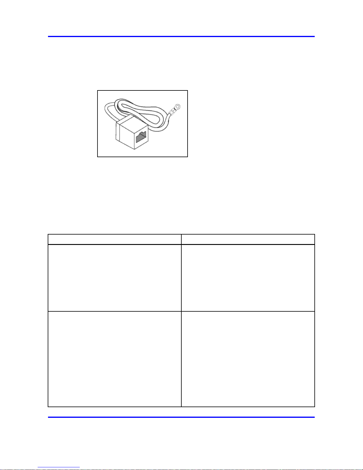
With new cable installations, Nortel recommends that the use of an ESD
discharge cable to reduce the potential for damage from static that can
build up in cables. See Figure 1 "ESD cable" (page 24).
Figure 1
ESD cable
See to install an ESD cable.
Ethernet Routing Switch 5000 series models
This module describes the 5000 Series switches.
The following table lists the different Ethernet Routing Switch 5000 Series
models and the key features for each switch.
Table 1
5000 Series Switch Platforms
5000 Series Switch Model Key features
Nortel Ethernet Routing Switch 5510-24T
• 24 ports
• 10/100/1GBase-T
• Layer 4
• Diffserv capability
• Stackable
• Two shared SFP transceiver ports
Nortel Ethernet Routing Switch 5510-48T A 48 port, 10/100/1GBase-T, Layer 4,
diffserv-capable, stackable Ethernet switch. This
switch contains two shared SFP transceiver
ports.
• 48 ports
• 10/100/1GBase-T
• Layer 4
• Diffserv capability
• Stackable
• Two shared SFP transceiver ports
ERS 5000 Series Installation
NN47200-300 04.03
13 April 2009
Copyright © 2008–2009 Nortel Networks

Ethernet Routing Switch 5000 series models 25
Table 1
5000 Series Switch Platforms (cont’d.)
Nortel Ethernet Routing Switch 5520-24T-PWR
•
24 ports
• 10/100/1GBase-T
•
Layer 4
•
Diffserv capability
• Stackable
•
Power over Ethernet (PoE) capability
•
Four shared SFP transceiver ports
Nortel Ethernet Routing Switch 5520-48T-PWR
• 48 ports
•
10/100/1GBase-T
• Layer 4
• Diffserv capability
• Stackable
• Power over Ethernet (PoE) capability
•
Four shared SFP transceiver ports
Nortel Ethernet Routing Switch 5530-24TFD
• 24 ports
• 10/100/1GBase-T
•
Layer 4
• Diffserv capability
• Stackable
• Twelve shared SFP transceiver ports
•
Two XFP transceiver ports
Nortel Ethernet Routing Switch 5632FD
• 24 fixed 100/1000FX SFP Ethernet ports
• Eight 10Gbit XFP ports
• Non-PoE
• Layer 2/Layer 3
• Stackable Ethernet switch
• 1.5 rack units (U) high
• Uses modular power supply units and
has two field-serviceable power supply
receptacles, which support 300W AC or DC
power supply modules.
ERS 5000 Series Installation
NN47200-300 04.03
13 April 2009
Copyright © 2008–2009 Nortel Networks

26 Installation fundamentals
Table 1
5000 Series Switch Platforms (cont’d.)
Nortel Ethernet Routing Switch 5650TD
•
48 port 10/100/1000 Base-T copper Ethernet
ports
•
Two 10Gbit XFP ports
•
Non-PoE
•
Layer 2/Layer 3
•
Stackable Ethernet switch
• 1 rack unit (U) high
•
Uses modular power supply units and
has two field-serviceable power supply
receptacles, which support 300W AC or DC
power supply modules.
Nortel Ethernet Routing Switch 5650TD-PWR
• 48 port 10/100/1000 Base-T copper Ethernet
ports
• Two 10Gbit XFP ports
•
PoE
• Layer 2/Layer 3
• Stackable Ethernet switch
• 1 rack unit (U) high
• Uses modular power supply units and
has two field-serviceable power supply
receptacles, which support 600W and
1000W AC or DC power supply modules.
Nortel Ethernet Routing Switch 5698TFD
• 96 fixed 10/100/1000 Base-T copper
Ethernet ports
• Six shared ports
•
Two 10Gbit XFP ports
• Non-PoE
• Layer 2/Layer 3
• Stackable Ethernet switch
• 2 rack units (U) high
• Uses modular power supply units and
has three field-serviceable power supply
receptacles, which support 300W AC or DC
power supply modules.
Nortel Ethernet Routing Switch 5698TFD-PWR
• 96 fixed 100/1000FX SFP Ethernet ports
ERS 5000 Series Installation
NN47200-300 04.03
13 April 2009
Copyright © 2008–2009 Nortel Networks
Ethernet Routing Switch 5000 series models 27
Table 1
5000 Series Switch Platforms (cont’d.)
•
Six 10Gbit XFP ports
•
PoE
•
Layer 2/Layer 3
• Stackable Ethernet switch
•
2 rack units (U) high
•
Uses modular power supply units and
has three field-serviceable power supply
receptacles, which support 1000W AC or DC
power supply modules.
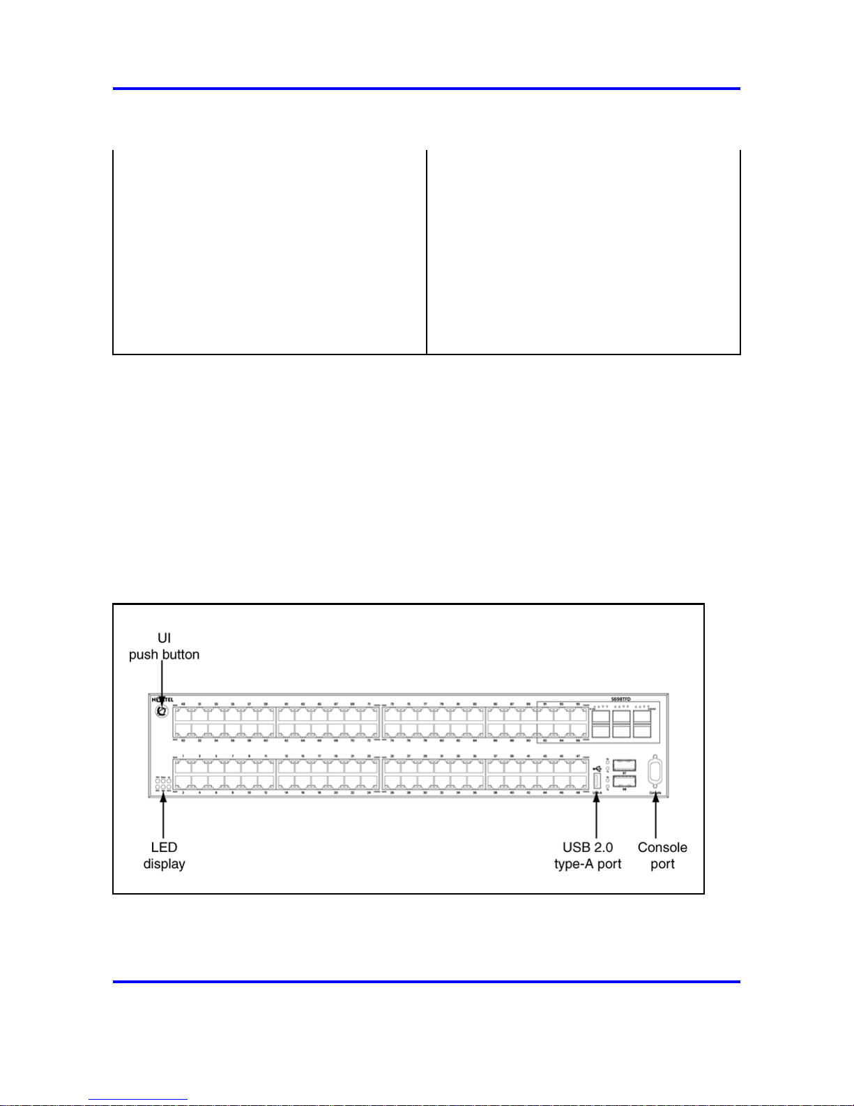
Common hardware features
The following hardware features are part of all 5000 Series switches:
• Two stack connectors, each operating an aggregate 80 or 144 Gbps
• UI push button
• LED display panel
•
Console port (DB-9 connector
• Two 10/100/1000 Mbps copper Ethernet diagnostics ports
• USB 2.0 Type-A port
The following figure shows the front panel of the 5698TFD switch.
ERS 5000 Series Installation
NN47200-300 04.03
13 April 2009
Copyright © 2008–2009 Nortel Networks
28 Installation fundamentals
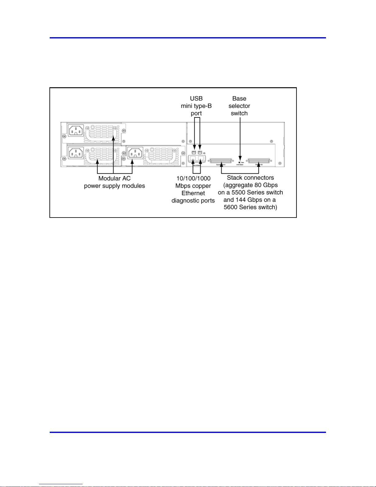
The following figure shows the rear panel of the 5698TFD switch. Not all
5000 Series switches have a USB port on the rear panel. See "Universal
Serial Bus ports on the Nortel Ethernet Routing Switch 5000 Series" (page
28) for information about switches that have the rear-panel USB port.
Universal Serial Bus ports on the Nortel Ethernet Routing Switch 5000
Series
The following switches include a Type A USB port on the front panel
adjacent to the console port, as well as a rear panel USB port (mini Type
B):
• 5530-24TFD
• 5632FD
• 5650TD
• 5650TD-PWR
• 5698TFD
• 5698TFD-PWR
The addition of USB ports will enable switch administrators to perform
tasks that were previously completed through TFTP with a commonly
available USB Mass Storage Device (also know as a flash drive or thumb
drive). These tasks include:
• software download
• syslog backup
• ASCII configuration file generation and download
File and system operations are limited by the size of the USB device in
use.
ERS 5000 Series Installation
NN47200-300 04.03
13 April 2009
Copyright © 2008–2009 Nortel Networks

Placement options and cables 29
Only USB drives that comply with the Mass Storage sub-section of
the USB 1.1 and USB 2.0 specification are supported. Support is not
extended to third-party devices that do not comply with these standards.
Off-the-shelf drives that do not comply with these standards may not
operate with the 5530-24TFD switch. Consult the documentation provided
with the USB drive to ensure compliance with these standards.
Attention: The USB port on the back panel of the Nortel Ethernet
Routing Switch 5530-24TFD and Nortel Ethernet Routing Switch 5600
Series models is not enabled.
Placement options and cables
The following sections describe the available placement option and
requirements, as well as cables for the Nortel Ethernet Routing Switch
5000 Series switch.
Environmental requirements
This module describes the environmental requirements for the Nortel
Ethernet Routing switches.
The Nortel Ethernet Routing switches must be properly mounted in a dry,
well-ventilated area with adequate power available for optimum operation.
See the environmental specifications in Table 8 "Job aid: Ethernet Routing
Switch 5500 Series environmental requirements" (page 62).
Placement options
You can mount 5000 Series switches on a flat surface such as a table
or shelf, or in a rack. Choose the mounting option that best suits your
location. The following sections describe the options.
Navigation
• "Switch installation on a table or shelf" (page 29)
• "Switch installation on the wall" (page 30)
• "Switch installation in an equipment rack, front mount option" (page 30)
• "Switch installation in an equipment rack, rear mount option" (page 30)
Choose the mounting solution that suits your requirements and site.
Switch installation on a table or shelf
You can mount 5000 Series switch on a flat surface such as a table or
shelf. See "Mounting on a table or shelf" (page 66), to install a single unit
on a table or shelf.
ERS 5000 Series Installation
NN47200-300 04.03
13 April 2009
Copyright © 2008–2009 Nortel Networks
30 Installation fundamentals
The surface, whether a shelf or table, must be able to support the
combined weight of the switch and attached cables; between 15 and 20
pounds (7 to 9 kilograms) for a 5500 Series switch, and between 21 and
33 pounds (9.5 to 15 kilograms) for a 5600 Series switch.
CAUTION
Do not place a Nortel Ethernet Power Supply Unit 10 or Nortel
Ethernet Redundant Power Supply 15 on top of a Nortel
Ethernet Routing Switch 5500 Series. The switch housing of
a 5500 Series Nortel Ethernet Routing Switch is not strong
enough to support the weight of these units.
Switch installation on the wall
You can mount 5000 Series switches on a wall. See "Mounting on a wall"
(page 68), to mount the switch on a wall.
Do not install a switch on a wall if the switch has a height greater than
1 rack unit (U).
Switch installation in an equipment rack, front mount option
You can mount 5000 Series switches in a rack with the front panel at the
front of the rack. See "Installing a front mounted switch in an equipment
rack" (page 70), to install the switch in a rack.
Before you begin this procedure, ensure that the equipment rack meets
the following requirements:
• A space equivalent to the rack height of the switch is provided for each
switch in an EIA or IEC standard 19-inch (48.2 centimeter) or TIA
23-inch (58.4 centimeter) equipment rack.
• The rack is bolted to the floor and braced if necessary.
• The rack is grounded to the same grounding electrode used by the
power service in the area. The ground path must be permanent and
must not exceed 1 ohm of resistance from the rack to the grounding
electrode.
CAUTION
When you mount the switch in a rack, do not stack units directly
on top of one another in the rack. Each unit must be secured
to the rack with the appropriate mounting brackets. Mounting
brackets are not designed to support multiple units.
Switch installation in an equipment rack, rear mount option
You can mount 5000 Series switches in a rack with the rear panel at the
front of the rack. See "Installing a rear mounted switch in an equipment
rack" (page 71), to install the switch in a rack.
ERS 5000 Series Installation
NN47200-300 04.03
13 April 2009
Copyright © 2008–2009 Nortel Networks
 Loading...