

Page 1

Succession Communication Server for
Enterprise 1000
Circuit Card Reference Guide
Document Number: 553-3023-211
Document Release: Standard 1.00
Date: June 2001
Year Publish FCC TM
Copyright © 2001 Nortel Networks
All Rights Reserved
Printed in Canada
Information is subject to change without notice. Nortel Networks reserves the right to make changes in design
or components as progress in engineering and manufacturing may warrant. This equipment has been tested
and found to comply with the limits for a Class A digital device pursuant to Part 15 of the FCC rules, and the
radio interference regulations of Industry Canada. These limits are designed to provide reasonable protection
against harmful interference when the equipment is operated in a commercial environment. This equipment
generates, uses and can radiate radio frequency energy, and if not installed and used in accordance with the
instruction manual, may cause harmful interference to radio communications. Operation of this equipment in a
residential area is likely to cause harmful interference in which case the user will be required to correct the
interference at their own expense.
Succession Communication Server for Enterprise 1000 is a trademark of Nortel Networks.
Succession Communication Server for Enterprise 1000 Circuit Card Reference Guide
Page 2

Page 3

4
Page 3 of 236
Revision history
June 2001
Standard, 1.00. This document is issued for Succession Communication
Server for Enterprise 1000 Release 1.00.
Succession Communication Server for Enterprise 1000 Circuit Card Reference Guide
Page 4

Page 4 of 236
553-3023-211 Standard 1.00 June 2001
Page 5

Contents
Contents Page 5 of 236
Contents . . . . . . . . . . . . . . . . . . . . . . . . . . . . . . . . . . 5
Succession System Controller card . . . . . . . . . . . 13
Contents . . . . . . . . . . . . . . . . . . . . . . . . . . . . . . . . . . . . . . . . . . . . . . . . 13
NTDK20FA Succession System Controller card . . . . . . . . . . . . . . . . . 13
Memory . . . . . . . . . . . . . . . . . . . . . . . . . . . . . . . . . . . . . . . . . . . . . . 14
100BaseT IP daughterboards. . . . . . . . . . . . . . . . . . . . . . . . . . . . . . 15
NTAK20 clock controller daughterboard . . . . . . . 25
Contents . . . . . . . . . . . . . . . . . . . . . . . . . . . . . . . . . . . . . . . . . . . . . . . . 25
Overview . . . . . . . . . . . . . . . . . . . . . . . . . . . . . . . . . . . . . . . . . . . . . . . 26
Clocking modes . . . . . . . . . . . . . . . . . . . . . . . . . . . . . . . . . . . . . . . . 27
Physical description . . . . . . . . . . . . . . . . . . . . . . . . . . . . . . . . . . . . . . . 28
Faceplate LEDs . . . . . . . . . . . . . . . . . . . . . . . . . . . . . . . . . . . . . . . . 28
Functional description . . . . . . . . . . . . . . . . . . . . . . . . . . . . . . . . . . . . . 29
Phase difference detector circuit . . . . . . . . . . . . . . . . . . . . . . . . . . . 29
Digital phase lock loops . . . . . . . . . . . . . . . . . . . . . . . . . . . . . . . . . 29
Digital to analog converter . . . . . . . . . . . . . . . . . . . . . . . . . . . . . . . 31
CPU-MUX bus interface . . . . . . . . . . . . . . . . . . . . . . . . . . . . . . . . . 32
Signal conditioning . . . . . . . . . . . . . . . . . . . . . . . . . . . . . . . . . . . . . 32
Sanity timer . . . . . . . . . . . . . . . . . . . . . . . . . . . . . . . . . . . . . . . . . . . 32
Microprocessor . . . . . . . . . . . . . . . . . . . . . . . . . . . . . . . . . . . . . . . . 32
External timing interface . . . . . . . . . . . . . . . . . . . . . . . . . . . . . . . . . 32
Hardware integrity and regulatory environment . . . . . . . . . . . . . . . 33
ITG Line 2.1 NTVQ55AA card . . . . . . . . . . . . . . . . . 35
Contents . . . . . . . . . . . . . . . . . . . . . . . . . . . . . . . . . . . . . . . . . . . . . . . . 35
ITG Line 2.1 card description . . . . . . . . . . . . . . . . . . . . . . . . . . . . . . . 35
ITG Line 2.1 controls, indicators and connectors . . . . . . . . . . . . . . . . 36
Faceplate components . . . . . . . . . . . . . . . . . . . . . . . . . . . . . . . . . . . 36
Backplane interfaces . . . . . . . . . . . . . . . . . . . . . . . . . . . . . . . . . . . . 38
Assembly description . . . . . . . . . . . . . . . . . . . . . . . . . . . . . . . . . . . 39
Succession Communication Server for Enterprise 1000 Circuit Card Reference Guide
Page 6

Page 6 of 236 Contents
ITG Line 2.1 card functional description . . . . . . . . . . . . . . . . . . . . . . . 39
ITGL Gateway functional description . . . . . . . . . . . . . . . . . . . . . . 39
Virtual TNs . . . . . . . . . . . . . . . . . . . . . . . . . . . . . . . . . . . . . . . . . . . 40
Terminal Proxy Server description . . . . . . . . . . . . . . . . . . . . . . . . . 40
Virtual Terminal Manager (VTM) description . . . . . . . . . . . . . . . . 41
Analog Trunk Cards - NT8D14
Universal Trunk Card . . . . . . . . . . . . . . . . . . . . . . . 43
Contents . . . . . . . . . . . . . . . . . . . . . . . . . . . . . . . . . . . . . . . . . . . . . . . . 43
Introduction . . . . . . . . . . . . . . . . . . . . . . . . . . . . . . . . . . . . . . . . . . . . . 44
Physical description . . . . . . . . . . . . . . . . . . . . . . . . . . . . . . . . . . . . . . . 47
Functional description . . . . . . . . . . . . . . . . . . . . . . . . . . . . . . . . . . . . . 49
Card interfaces . . . . . . . . . . . . . . . . . . . . . . . . . . . . . . . . . . . . . . . . 50
Card control functions . . . . . . . . . . . . . . . . . . . . . . . . . . . . . . . . . . . 50
Operation . . . . . . . . . . . . . . . . . . . . . . . . . . . . . . . . . . . . . . . . . . . . . . . 51
Loop start operation . . . . . . . . . . . . . . . . . . . . . . . . . . . . . . . . . . . . 51
Ground start operation . . . . . . . . . . . . . . . . . . . . . . . . . . . . . . . . . . 54
Direct inward dial operation . . . . . . . . . . . . . . . . . . . . . . . . . . . . . . 63
Two-way, loop dial repeating, tie trunk operation . . . . . . . . . . . . . 63
Senderized operation for DID and two-way loop DR trunks . . . . . 71
Outgoing automatic, incoming dial operation . . . . . . . . . . . . . . . . . 74
Recorded Announcement trunk operation . . . . . . . . . . . . . . . . . . . 79
Electrical specifications . . . . . . . . . . . . . . . . . . . . . . . . . . . . . . . . . . . . 83
Power requirements . . . . . . . . . . . . . . . . . . . . . . . . . . . . . . . . . . . . . 84
Foreign and surge voltage protection . . . . . . . . . . . . . . . . . . . . . . . 85
Environmental specifications . . . . . . . . . . . . . . . . . . . . . . . . . . . . . 85
Connector pin assignments . . . . . . . . . . . . . . . . . . . . . . . . . . . . . . . . . 85
Configuration . . . . . . . . . . . . . . . . . . . . . . . . . . . . . . . . . . . . . . . . . . . 87
Jumper strap settings . . . . . . . . . . . . . . . . . . . . . . . . . . . . . . . . . . . . 87
Service change entries . . . . . . . . . . . . . . . . . . . . . . . . . . . . . . . . . . . 87
Applications . . . . . . . . . . . . . . . . . . . . . . . . . . . . . . . . . . . . . . . . . . . . . 94
Paging trunk operation . . . . . . . . . . . . . . . . . . . . . . . . . . . . . . . . . . 94
Music operation . . . . . . . . . . . . . . . . . . . . . . . . . . . . . . . . . . . . . . . . 95
553-3023-211 Standard 1.00 June 2001
Page 7

Contents Page 7 of 236
NT8D15 E&M Trunk Card . . . . . . . . . . . . . . . . . . . . 97
Contents . . . . . . . . . . . . . . . . . . . . . . . . . . . . . . . . . . . . . . . . . . . . . . . . 97
Introduction . . . . . . . . . . . . . . . . . . . . . . . . . . . . . . . . . . . . . . . . . . . . . 98
Physical description . . . . . . . . . . . . . . . . . . . . . . . . . . . . . . . . . . . . . . . 99
Functional description . . . . . . . . . . . . . . . . . . . . . . . . . . . . . . . . . . . . . 100
Card interfaces . . . . . . . . . . . . . . . . . . . . . . . . . . . . . . . . . . . . . . . . . 103
Card control functions . . . . . . . . . . . . . . . . . . . . . . . . . . . . . . . . . . . 105
Maintenance features . . . . . . . . . . . . . . . . . . . . . . . . . . . . . . . . . . . . 109
Operation . . . . . . . . . . . . . . . . . . . . . . . . . . . . . . . . . . . . . . . . . . . . . . . 109
Signaling and call control . . . . . . . . . . . . . . . . . . . . . . . . . . . . . . . . 109
Electrical specifications . . . . . . . . . . . . . . . . . . . . . . . . . . . . . . . . . . . . 121
Trunk interface electrical characteristics . . . . . . . . . . . . . . . . . . . . . 121
Power requirements . . . . . . . . . . . . . . . . . . . . . . . . . . . . . . . . . . . . . 122
Environmental specifications . . . . . . . . . . . . . . . . . . . . . . . . . . . . . 122
Foreign and surge voltage protection . . . . . . . . . . . . . . . . . . . . . . . 122
Connector pin assignments . . . . . . . . . . . . . . . . . . . . . . . . . . . . . . . . . . 122
Configuration . . . . . . . . . . . . . . . . . . . . . . . . . . . . . . . . . . . . . . . . . . . . 126
Jumper settings . . . . . . . . . . . . . . . . . . . . . . . . . . . . . . . . . . . . . . . . 126
Software service entries . . . . . . . . . . . . . . . . . . . . . . . . . . . . . . . . . . 126
Applications . . . . . . . . . . . . . . . . . . . . . . . . . . . . . . . . . . . . . . . . . . . . . 130
Paging trunk operation . . . . . . . . . . . . . . . . . . . . . . . . . . . . . . . . . . 130
NTAK09 1.5 Mb DTI/PRI card . . . . . . . . . . . . . . . . . 133
Contents . . . . . . . . . . . . . . . . . . . . . . . . . . . . . . . . . . . . . . . . . . . . . . . . 133
Overview . . . . . . . . . . . . . . . . . . . . . . . . . . . . . . . . . . . . . . . . . . . . . . . 134
Functional description . . . . . . . . . . . . . . . . . . . . . . . . . . . . . . . . . . . . . 134
Physical description . . . . . . . . . . . . . . . . . . . . . . . . . . . . . . . . . . . . . . . 135
NTAK09 DTI/PRI power on self-test . . . . . . . . . . . . . . . . . . . . . . . 137
NTAK20 power on self-test . . . . . . . . . . . . . . . . . . . . . . . . . . . . . . 138
NTAK93 self-test . . . . . . . . . . . . . . . . . . . . . . . . . . . . . . . . . . . . . . 138
DTI/PRI local self-test . . . . . . . . . . . . . . . . . . . . . . . . . . . . . . . . . . . 139
Power requirements . . . . . . . . . . . . . . . . . . . . . . . . . . . . . . . . . . . . . 139
Foreign and surge voltage protection . . . . . . . . . . . . . . . . . . . . . . . 139
Architecture . . . . . . . . . . . . . . . . . . . . . . . . . . . . . . . . . . . . . . . . . . . . . 139
Succession Communication Server for Enterprise 1000 Circuit Card Reference Guide
Page 8

Page 8 of 236 Contents
Signaling interface . . . . . . . . . . . . . . . . . . . . . . . . . . . . . . . . . . . . . 139
Interconnection . . . . . . . . . . . . . . . . . . . . . . . . . . . . . . . . . . . . . . . . 139
Microprocessor . . . . . . . . . . . . . . . . . . . . . . . . . . . . . . . . . . . . . . . . 140
Digital pad . . . . . . . . . . . . . . . . . . . . . . . . . . . . . . . . . . . . . . . . . . . . 140
D-channel interface . . . . . . . . . . . . . . . . . . . . . . . . . . . . . . . . . . . . . 141
DS-1 Carrier interface . . . . . . . . . . . . . . . . . . . . . . . . . . . . . . . . . . . 142
Clock controller interface . . . . . . . . . . . . . . . . . . . . . . . . . . . . . . . . 143
Clock rate converter . . . . . . . . . . . . . . . . . . . . . . . . . . . . . . . . . . . . 144
NTAK10 2.0 Mb DTI card . . . . . . . . . . . . . . . . . . . . 145
Contents . . . . . . . . . . . . . . . . . . . . . . . . . . . . . . . . . . . . . . . . . . . . . . . . 145
Overview . . . . . . . . . . . . . . . . . . . . . . . . . . . . . . . . . . . . . . . . . . . . . . . 145
Functional description . . . . . . . . . . . . . . . . . . . . . . . . . . . . . . . . . . . . . 146
Physical description . . . . . . . . . . . . . . . . . . . . . . . . . . . . . . . . . . . . 147
Power requirements . . . . . . . . . . . . . . . . . . . . . . . . . . . . . . . . . . . . . 148
Environment . . . . . . . . . . . . . . . . . . . . . . . . . . . . . . . . . . . . . . . . . . 148
Architecture . . . . . . . . . . . . . . . . . . . . . . . . . . . . . . . . . . . . . . . . . . . . . 148
DS-30X interface . . . . . . . . . . . . . . . . . . . . . . . . . . . . . . . . . . . . . . 149
Signaling interface . . . . . . . . . . . . . . . . . . . . . . . . . . . . . . . . . . . . . 149
Carrier interface . . . . . . . . . . . . . . . . . . . . . . . . . . . . . . . . . . . . . . . 151
Clock controller interface . . . . . . . . . . . . . . . . . . . . . . . . . . . . . . . . . . 152
Switch settings . . . . . . . . . . . . . . . . . . . . . . . . . . . . . . . . . . . . . . . . 153
NTBK50 2.0 Mb PRI card . . . . . . . . . . . . . . . . . . . . 155
Contents . . . . . . . . . . . . . . . . . . . . . . . . . . . . . . . . . . . . . . . . . . . . . . . . 155
Overview . . . . . . . . . . . . . . . . . . . . . . . . . . . . . . . . . . . . . . . . . . . . . . . 155
Functional description . . . . . . . . . . . . . . . . . . . . . . . . . . . . . . . . . . . . . 156
Physical description . . . . . . . . . . . . . . . . . . . . . . . . . . . . . . . . . . . . . . . 157
Power requirements . . . . . . . . . . . . . . . . . . . . . . . . . . . . . . . . . . . . . 158
Environment . . . . . . . . . . . . . . . . . . . . . . . . . . . . . . . . . . . . . . . . . . 158
Architecture . . . . . . . . . . . . . . . . . . . . . . . . . . . . . . . . . . . . . . . . . . . . . 160
DS-30X interface . . . . . . . . . . . . . . . . . . . . . . . . . . . . . . . . . . . . . . 160
Signaling interface . . . . . . . . . . . . . . . . . . . . . . . . . . . . . . . . . . . . . 161
Carrier interface . . . . . . . . . . . . . . . . . . . . . . . . . . . . . . . . . . . . . . . 162
Carrier grounding . . . . . . . . . . . . . . . . . . . . . . . . . . . . . . . . . . . . . . 162
553-3023-211 Standard 1.00 June 2001
Page 9

Contents Page 9 of 236
CEPT transceiver . . . . . . . . . . . . . . . . . . . . . . . . . . . . . . . . . . . . . . . 164
Slip control . . . . . . . . . . . . . . . . . . . . . . . . . . . . . . . . . . . . . . . . . . . 164
D-channel support interface . . . . . . . . . . . . . . . . . . . . . . . . . . . . . . 164
Card-LAN interface . . . . . . . . . . . . . . . . . . . . . . . . . . . . . . . . . . . . . 165
NTAK79 2.0 Mb PRI card . . . . . . . . . . . . . . . . . . . . . 167
Contents . . . . . . . . . . . . . . . . . . . . . . . . . . . . . . . . . . . . . . . . . . . . . . . . 167
Overview . . . . . . . . . . . . . . . . . . . . . . . . . . . . . . . . . . . . . . . . . . . . . . . 167
Functional description . . . . . . . . . . . . . . . . . . . . . . . . . . . . . . . . . . . . . 168
Physical description . . . . . . . . . . . . . . . . . . . . . . . . . . . . . . . . . . . . . . . 169
NTAK79 switches . . . . . . . . . . . . . . . . . . . . . . . . . . . . . . . . . . . . . . 171
Power requirements . . . . . . . . . . . . . . . . . . . . . . . . . . . . . . . . . . . . . 173
Environment . . . . . . . . . . . . . . . . . . . . . . . . . . . . . . . . . . . . . . . . . . 173
Architecture . . . . . . . . . . . . . . . . . . . . . . . . . . . . . . . . . . . . . . . . . . . . . 173
DS-30X interface . . . . . . . . . . . . . . . . . . . . . . . . . . . . . . . . . . . . . . . 174
Signaling interface . . . . . . . . . . . . . . . . . . . . . . . . . . . . . . . . . . . . . . 175
Carrier interface . . . . . . . . . . . . . . . . . . . . . . . . . . . . . . . . . . . . . . . . 175
Carrier grounding . . . . . . . . . . . . . . . . . . . . . . . . . . . . . . . . . . . . . . 176
CEPT transceiver . . . . . . . . . . . . . . . . . . . . . . . . . . . . . . . . . . . . . . . 177
Slip control . . . . . . . . . . . . . . . . . . . . . . . . . . . . . . . . . . . . . . . . . . . 177
D-channel support interface . . . . . . . . . . . . . . . . . . . . . . . . . . . . . . 177
Card-LAN interface . . . . . . . . . . . . . . . . . . . . . . . . . . . . . . . . . . . . . 178
Clock controller interface . . . . . . . . . . . . . . . . . . . . . . . . . . . . . . . . 179
NTAK93 D-channel handler
interface daughterboard . . . . . . . . . . . . . . . . . . . . . 181
Contents . . . . . . . . . . . . . . . . . . . . . . . . . . . . . . . . . . . . . . . . . . . . . . . . 181
Overview . . . . . . . . . . . . . . . . . . . . . . . . . . . . . . . . . . . . . . . . . . . . . . . 181
Features and functions . . . . . . . . . . . . . . . . . . . . . . . . . . . . . . . . . . . . . 182
Physical description . . . . . . . . . . . . . . . . . . . . . . . . . . . . . . . . . . . . . . . 183
Faceplate LEDs . . . . . . . . . . . . . . . . . . . . . . . . . . . . . . . . . . . . . . . . 183
Power consumption . . . . . . . . . . . . . . . . . . . . . . . . . . . . . . . . . . . . . 183
Functional description . . . . . . . . . . . . . . . . . . . . . . . . . . . . . . . . . . . . . 183
Microprocessors . . . . . . . . . . . . . . . . . . . . . . . . . . . . . . . . . . . . . . . 183
DMA controller . . . . . . . . . . . . . . . . . . . . . . . . . . . . . . . . . . . . . . . . 184
Succession Communication Server for Enterprise 1000 Circuit Card Reference Guide
Page 10

Page 10 of 236 Contents
Random Access Memory (RAM) . . . . . . . . . . . . . . . . . . . . . . . . . . 184
Read Only Memory (ROM) . . . . . . . . . . . . . . . . . . . . . . . . . . . . . . 184
LAPD Data Link/Asynchronous Controller . . . . . . . . . . . . . . . . . . 184
Counter/Timer controller . . . . . . . . . . . . . . . . . . . . . . . . . . . . . . . . 184
Software interface circuit . . . . . . . . . . . . . . . . . . . . . . . . . . . . . . . . 184
DPNSS/DCHI Port . . . . . . . . . . . . . . . . . . . . . . . . . . . . . . . . . . . . . 184
D-Port – SDTI/PRI interface . . . . . . . . . . . . . . . . . . . . . . . . . . . . . . 185
NTBK51 Downloadable D-channel Handler
daughterboard . . . . . . . . . . . . . . . . . . . . . . . . . . . . 187
Contents . . . . . . . . . . . . . . . . . . . . . . . . . . . . . . . . . . . . . . . . . . . . . . . . 187
Overview . . . . . . . . . . . . . . . . . . . . . . . . . . . . . . . . . . . . . . . . . . . . . . . 188
Features and functions . . . . . . . . . . . . . . . . . . . . . . . . . . . . . . . . . . . . . 188
Physical description . . . . . . . . . . . . . . . . . . . . . . . . . . . . . . . . . . . . . . . 188
Functional description . . . . . . . . . . . . . . . . . . . . . . . . . . . . . . . . . . . . . 189
Microprocessors . . . . . . . . . . . . . . . . . . . . . . . . . . . . . . . . . . . . . . . 189
Main Memory . . . . . . . . . . . . . . . . . . . . . . . . . . . . . . . . . . . . . . . . . 190
Shared Memory . . . . . . . . . . . . . . . . . . . . . . . . . . . . . . . . . . . . . . . . 190
EPROM Memory . . . . . . . . . . . . . . . . . . . . . . . . . . . . . . . . . . . . . . 190
Flash EPROM Memory . . . . . . . . . . . . . . . . . . . . . . . . . . . . . . . . . 190
EEPROM Memory . . . . . . . . . . . . . . . . . . . . . . . . . . . . . . . . . . . . . 190
Serial Communication Controller . . . . . . . . . . . . . . . . . . . . . . . . . . 190
Sanity Timer . . . . . . . . . . . . . . . . . . . . . . . . . . . . . . . . . . . . . . . . . . 191
Bus Timer . . . . . . . . . . . . . . . . . . . . . . . . . . . . . . . . . . . . . . . . . . . . 191
Download Operation . . . . . . . . . . . . . . . . . . . . . . . . . . . . . . . . . . . . . . 191
System Initialization . . . . . . . . . . . . . . . . . . . . . . . . . . . . . . . . . . . . 191
Card enabling or application enabling . . . . . . . . . . . . . . . . . . . . . . 191
Card reset . . . . . . . . . . . . . . . . . . . . . . . . . . . . . . . . . . . . . . . . . . . . 192
Background audit . . . . . . . . . . . . . . . . . . . . . . . . . . . . . . . . . . . . . . 192
NTRB21 DTI/PRI/DCH TMDI card . . . . . . . . . . . . . . 193
Contents . . . . . . . . . . . . . . . . . . . . . . . . . . . . . . . . . . . . . . . . . . . . . . . . 193
Overview . . . . . . . . . . . . . . . . . . . . . . . . . . . . . . . . . . . . . . . . . . . . . . . 193
Functional description . . . . . . . . . . . . . . . . . . . . . . . . . . . . . . . . . . . . . 195
Hardware description . . . . . . . . . . . . . . . . . . . . . . . . . . . . . . . . . . . . . . 195
553-3023-211 Standard 1.00 June 2001
Page 11

Contents Page 11 of 236
NTRB21 TMDI card . . . . . . . . . . . . . . . . . . . . . . . . . . . . . . . . . . . . 195
Physical description . . . . . . . . . . . . . . . . . . . . . . . . . . . . . . . . . . . . . . . 196
Power requirements . . . . . . . . . . . . . . . . . . . . . . . . . . . . . . . . . . . . . 200
Foreign and surge voltage protection . . . . . . . . . . . . . . . . . . . . . . . 200
Architecture . . . . . . . . . . . . . . . . . . . . . . . . . . . . . . . . . . . . . . . . . . . . . 200
Signaling interface . . . . . . . . . . . . . . . . . . . . . . . . . . . . . . . . . . . . . . 200
Interconnection . . . . . . . . . . . . . . . . . . . . . . . . . . . . . . . . . . . . . . . . 200
Microprocessor . . . . . . . . . . . . . . . . . . . . . . . . . . . . . . . . . . . . . . . . 200
Digital pad . . . . . . . . . . . . . . . . . . . . . . . . . . . . . . . . . . . . . . . . . . . . 201
D-channel interface . . . . . . . . . . . . . . . . . . . . . . . . . . . . . . . . . . . . . 202
DS-1 Carrier interface . . . . . . . . . . . . . . . . . . . . . . . . . . . . . . . . . . . 203
NTAK20 Clock Controller (CC) daughterboard . . . . . . . . . . . . . . . 204
NTAK02 SDI/DCH card . . . . . . . . . . . . . . . . . . . . . . 207
Contents . . . . . . . . . . . . . . . . . . . . . . . . . . . . . . . . . . . . . . . . . . . . . . . . 207
Introduction . . . . . . . . . . . . . . . . . . . . . . . . . . . . . . . . . . . . . . . . . . . . . 207
NTAK02 SDI/DCH card . . . . . . . . . . . . . . . . . . . . . . . . . . . . . . . . . . . 207
Connecting to the ports . . . . . . . . . . . . . . . . . . . . . . . . . . . . . . . . . . 210
Characteristics of the low speed port . . . . . . . . . . . . . . . . . . . . . . . . 211
Characteristics of the high speed port . . . . . . . . . . . . . . . . . . . . . . . 214
Analog line cards . . . . . . . . . . . . . . . . . . . . . . . . . . 215
Contents . . . . . . . . . . . . . . . . . . . . . . . . . . . . . . . . . . . . . . . . . . . . . . . . 215
NT1R20 Off-Premise Station Analog Line Card . . . . . . . . . . . . . . . . . 216
Overview . . . . . . . . . . . . . . . . . . . . . . . . . . . . . . . . . . . . . . . . . . . . . . . 216
Physical description . . . . . . . . . . . . . . . . . . . . . . . . . . . . . . . . . . . . . . . 216
Self Test . . . . . . . . . . . . . . . . . . . . . . . . . . . . . . . . . . . . . . . . . . . . . . 217
Functional description . . . . . . . . . . . . . . . . . . . . . . . . . . . . . . . . . . . . . 217
Card interfaces . . . . . . . . . . . . . . . . . . . . . . . . . . . . . . . . . . . . . . . . . 217
Card functions . . . . . . . . . . . . . . . . . . . . . . . . . . . . . . . . . . . . . . . . . 218
Operation . . . . . . . . . . . . . . . . . . . . . . . . . . . . . . . . . . . . . . . . . . . . . . . 220
Incoming calls . . . . . . . . . . . . . . . . . . . . . . . . . . . . . . . . . . . . . . . . . 220
Outgoing calls . . . . . . . . . . . . . . . . . . . . . . . . . . . . . . . . . . . . . . . . . 221
Off-premise Station application . . . . . . . . . . . . . . . . . . . . . . . . . . . 221
Succession Communication Server for Enterprise 1000 Circuit Card Reference Guide
Page 12

Page 12 of 236 Contents
Other applications . . . . . . . . . . . . . . . . . . . . . . . . . . . . . . . . . . . . . . 223
Transmission considerations . . . . . . . . . . . . . . . . . . . . . . . . . . . . . . 223
NT1R20 OPS analog line card installation . . . . . . . . . . . . . . . . . . . 226
NT5K02 Flexible Analog Line Card . . . . . . . . . . . . . . . . . . . . . . . . . . 226
NT8D03 Analog Line Card . . . . . . . . . . . . . . . . . . . . . . . . . . . . . . . . . 228
NT8D09 Analog Message Waiting Line Card . . . . . . . . . . . . . . . . . . 228
Description . . . . . . . . . . . . . . . . . . . . . . . . . . . . . . . . . . . . . . . . . . . 228
Physical description . . . . . . . . . . . . . . . . . . . . . . . . . . . . . . . . . . . . 229
Functional description . . . . . . . . . . . . . . . . . . . . . . . . . . . . . . . . . . . 230
Technical summary . . . . . . . . . . . . . . . . . . . . . . . . . . . . . . . . . . . . . . . 231
Analog line interface . . . . . . . . . . . . . . . . . . . . . . . . . . . . . . . . . . . . 231
Power requirements . . . . . . . . . . . . . . . . . . . . . . . . . . . . . . . . . . . . . 234
Foreign and surge voltage protections . . . . . . . . . . . . . . . . . . . . . . 234
Overload level . . . . . . . . . . . . . . . . . . . . . . . . . . . . . . . . . . . . . . . . . 234
Supported Applications . . . . . . . . . . . . . . . . . . . . . 235
553-3023-211 Standard 1.00 June 2001
Page 13

24
Page 13 of 236
Succession System Controller card
Contents
This section contains information on the following topics:
NTDK20FA Succession System Controller card . .. . . . . . . . . . . . . . . . 13
Memory . . . . . . . . . . . . . . . . . . . . . . . . . . . . . . . . . . . . . . . . . . . . . . . . . 14
100BaseT IP daughterboards. . . . . . . . . . . . . . . . . . . . . . . . . . . . . . . . . 15
This chapter describes the NTDK20FA Succession System Controller (SSC)
card used with the Succession Communication Server for Enterprise
(CSE) 1000 system.
NTDK20FA Succession System Controller card
The NTDK20FA Succession System Controller card is used in the
Succession CSE 1000 Call Server and Media Gateway. It controls call
processing, stores system and customer data, and prov ides various 100BaseT
IP interfaces. The NTDK20FA card is the minimum vintage of SSC that can
be used in the Succession CSE 1000 Call Server and Media Gateway. See
Figure 5 on page 20.
The Succession CSE 1000 Call Server supports up to 640 i2000 series
telephones. More than one Call Server can be installed on a network.
The NTDK20FA SSC card is comprised of the following components and
features:
• NTTK13 Flash daughterboard memory, NTAK19 SIMM module
(16 MB) DRAM, and Backup memory
• up to two 100BaseT IP daughterboards
• two PCMCIA sockets
Succession Communication Server for Enterprise 1000 Circuit Card Reference Guide
Page 14

Page 14 of 236 Succession System Controller card
• three Serial Data Interface (SDI) ports
• 32 channels of Conferencing (64 if one dual port 100BaseT IP
daughterboard is present, or 96 if two dual port 100BaseT IP
daughterboards are present)
• one 10BaseT port
• 30 channels of Ton e and Digit Switch (TDS) and a combination of eight
Digitone Receivers (DTR) or Extended Tone Detectors (XTD)
• additional tone service ports (four units of M F C/MFE/MFK5/MFK6/
MFR or eight DTR/XTD units)
Memory
The majority of system and customer configured data is both controlled and
stored on the NTDK20FA SSC card’s Flash ROM. An active and backup
copy of customer data is also kept on the Flash ROM.
The NTDK20FA SSC card also retains a copy of customer files in the event
of data loss, in an area called the Backup flash drive. The NTDK20FA SSC
card is equipped with 8 MB of temporary memory space called DRAM.
DRAM func tions much like RAM on a computer system, storing stor es and
processes temporary automated routines and user-programmed commands
while the system is running. The DRAM on the SSC card stores operating
system files, user files, overlay data, patch codes, and the active copy of the
customer database.
The NTDK20FA SSC card’s Flash daughterboard, the NTTK13, performs
most of the system software storage and data processing for the Succession
CSE 1000.
NTTK13 daughterboard
The NTTK13 is a 48 MB daughterboard comprised of Flash ROM and
Primary Flash drive. It is required in the Call Server and Media Gateway.
• The Flash ROM holds 32 MB of ROM memory, comprising operating
system data and overlay programs. Flash ROM is expandable using an
expansion flash daughterboard.
553-3023-211 Standard 1.00 June 2001
Page 15

Succession System Controller card Page 15 of 236
• The Primary Flash drive contains 16 MB of storage space. Most of the
data storage is allocated to the Primary Flash drive - the main storage
area of customer configured data.
Other system data such as the Secure Storage Area (SSA) also resides in the
Flash drive. The SSA holds data that must survive power interruptions.
The Boot ROM is a 2 MB storage device located on the NTDK20FA SSC
card. The Boot ROM contains the bo ot code, sy stem d ata, patc h data and t he
backup copy of the Primary Flash drive’s customer database.
100BaseT IP daughterboards.
A 100BaseT IP Daughterboard mounted on the NTDK20FA SSC card allows
the connection of the Call Server to a Media Gateway. See Figure 5 on
page 20.
Each daughterboard increases the number of conference chann els by 32. The
maximum number of conference ports is 96. Table 1 on page 18 provides the
ports, cables and connection data on the IP daughterboards.
The NTDK83 (dual-port) 100BaseT IP daughterboard mounts on the
NTDK20FA SSC card in the Call Server. It provides connectivity to two
Media Gateways, and their associated Media Gateway Expansions, located
within 100 m of the Call Server. An optional secon d NTDK83 daughterboard
can be mounted on the NTDK20FA SSC car d in th e C all Server . Adding the
second NTDK83 daughterboard provides support for up to four Media
Gateways and their associated Media Gateway Expansions. See Figure 1 on
page 16.
The NTDK99AA (single-port) daughterboard is mounted on the SSC card in
the Media Gateway to provide connectivity to the Call Server. See Figure 2
on page 16.
Note: Third party media conversion devices can be used to extend the
range of Media Gateways from the Succession CSE 1000 Call Server.
The IMC Networks Ethernet Compatible Media Converter with a
McLIM Tx/Fx-SM/Plus module was tested by Nortel Networks. It
provided acceptable transmission between the Call Server and the Media
Gateway located up to 40 kms apart.
Succession Communication Server for Enterprise 1000 Circuit Card Reference Guide
Page 16
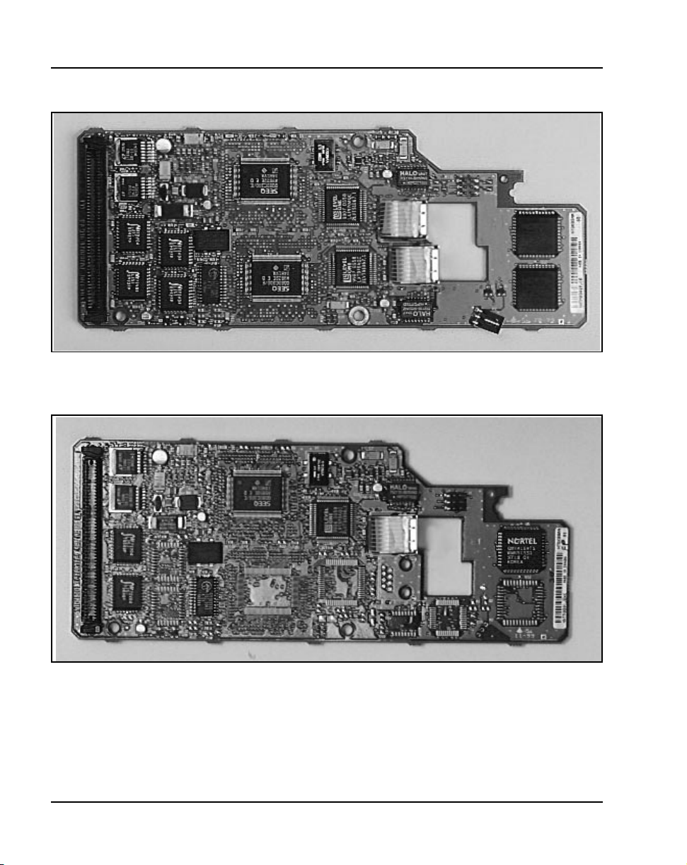
Page 16 of 236 Succession System Controller card
Figure 1
NTDK83AA dual-port 100BaseT IP daughterboard
Figure 2
NTDK99A single-port 100BaseT IP daughterboard
553-3023-211 Standard 1.00 June 2001
Page 17
Succession System Controller card Page 17 of 236
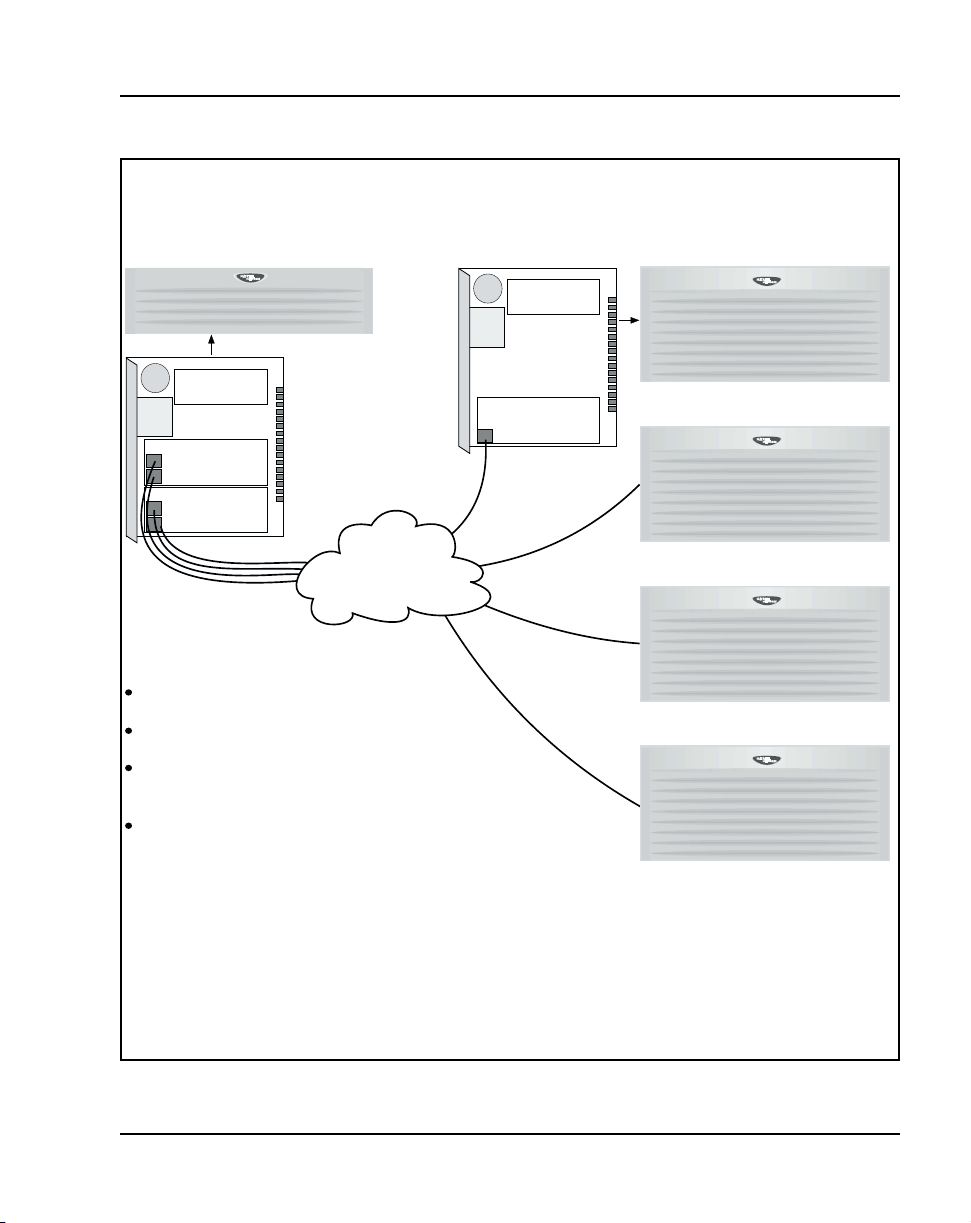
Figure 3
Call Server connection to Media Gateways
Call Server connection to Media Gateways
Call Server Media Gateways
Software
Daughterboard
Software
Daughterboard
Dual Port
100BaseT
Daughterboard
Dual Port
100BaseT
Daughterboard
LAN
Single Port
100BaseT
Daughterboard
The Call Server connects to the LAN via
dual port daughterboards.
One 100BaseT connection is required for
each Media Gateway.
Each Media Gateway contains an SSC with
a single port IP daughterboard and a
software daughterboard.
The single port IP daughterboard connects
to the LAN via 100BaseT.
Succession Communication Server for Enterprise 1000 Circuit Card Reference Guide
553-CSE0001
Page 18

Page 18 of 236 Succession System Controller card
Call Servers can be connected to Media Gateways in the following ways:
• use 100BaseT to connect to the LAN for voice distribution over a data
network
• use 100BaseT cable if connected point-to-point (directly) to the Media
Gateway. The NTTK34AA crossover cable must be used. Media
Gateways can be located up to 100 meters from the Call Server.
• use Media Conversion devices (third party converters) to convert
100BaseT to fiber for distances from 100 m to 40 km.
See Figure 3 on page 1 7.
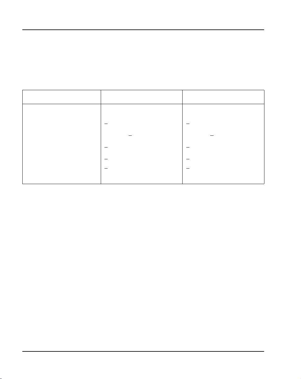
Table 1
Expansion Daughterboards
Daughterboard
NTDK99 (used in
Media Gateway)
NTDK83 (used in
Call Server
Number
of ports
one NTDK8305
two
Cable type
100BaseT 2m
extension cable –
provides external
access to the
100BaseT port, and
EMC containment.
Use the supplied
NTTK4AA UTP CAT 5
RJ45 2 m cross-over
cable to connect the
Call Server and Media
Gateway using the
100BaseT
daughterboards.
The NTTK34AA crossover cable must be
used with the
NTDK8305 2 m
extension cable if
connecting point-topoint.
Max. distance between Call
Server and Media Gateways
Media Gateways can be
located up to100 m (328 ft.)
from the Call Server if
connected point-to-point, or
up to 40 km (24 miles) from
the Call Server if a third party
converter is used to convert to
fiber.
553-3023-211 Standard 1.00 June 2001
Page 19
Succession System Controller card Page 19 of 236
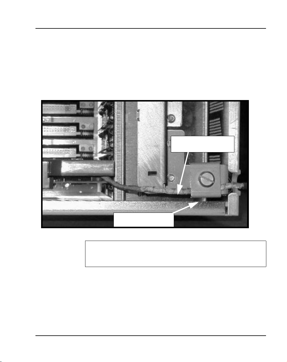
EMC grounding clip
For Media Gateways connected with 100BaseT cable, the cable must be
routed though the EMC grounding clip. This ensures electrical contact
between the ground rail and 100BaseT cable for EMC containment.
The NTTK43AA EMC grounding clip is used on the Media Gateway.
Figure 4
EMC Grounding Clip on the Media Gateway
100BaseT cables
secured with a cable tie
100BaseT Cable
EMC Grounding Clip
CAUTION
Use of the EMC grounding clip is required for EMC compliance.
For further information or installation instructio ns, refer to Succession
Communication Server for Enterprise 1000 Planning and Installation Guide
(553-3023-210).
Succession Communication Server for Enterprise 1000 Circuit Card Reference Guide
Page 20
Page 20 of 236 Succession System Controller card
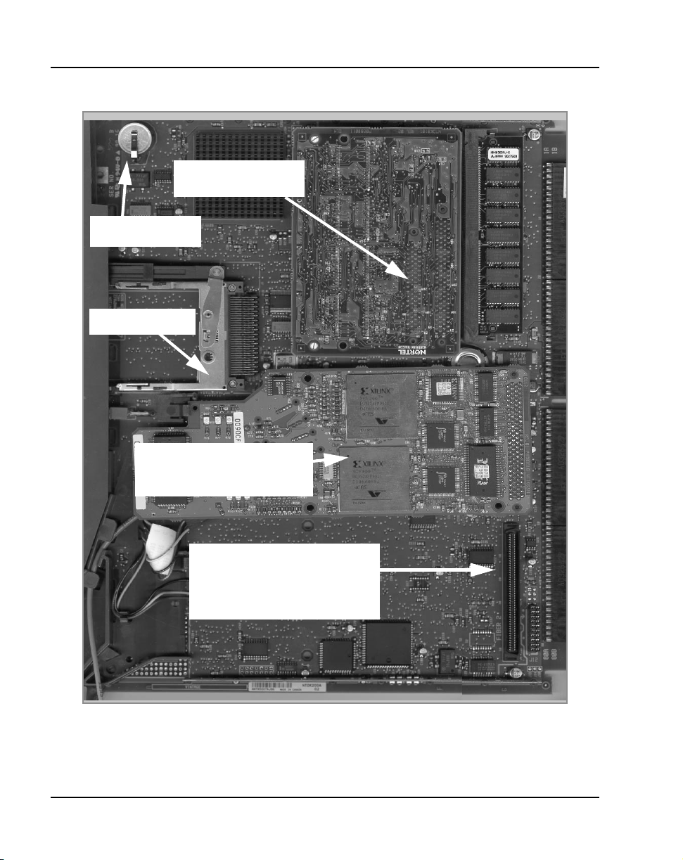
Figure 5
NTDK20FA SSC card and Expansion Daughterboard in the Succession CSE 1000 Call Server
Flash ROM Drive
Security Device
PCMCIA Drive
100BaseT Daughterboard
Ports 1 & 3 for first two
Media Gateways
Connector for 2nd
100BaseT Daughterboard.
Ports 2 and 4 for third and
fourth Media Gateways
553-3023-211 Standard 1.00 June 2001
Page 21

Succession System Controller card Page 21 of 236
PCMCIA interface
The NTDK20FA SSC card has a PCMCIA interface through a socket located
on its faceplate. The PCMCIA socket can accommodate a Software Delivery
card used for software upgrading and as backup media.
Security device for the Succession CSE 1000
The SSC card in each Media Gateway must contain a NTDK57DA Security
device which is keyed to match the NTDK57AA Secur ity device on the Call
Server.
This maintains the requirement of a single keycode for each Succession CSE
1000 system. Refer to Figure 5 on page 20 for the location of the device.
The main objectives of this security scheme are to:
• allow the system to operate as a single system when all links are up.
• allow the Media Gateway to continue operating with its existing
configuration in the event of a failure of the Succession CSE 1000 Call
Server, or the failure of the link to the Succession CSE 1000 Call Server
from the Media Gateway.
• prevent users from configuring or using unauthorized TNs or features.
The Media Gateway security device provides the following capabilities for
the Media Gateway:
• System software can be in stalled but no calls can be processed or features
activated until communication with the Succession CSE 1000 Call
Server has been established and a match between the security ID of the
Succession CSE 1000 Call Server and the Media Gateway has been
confirmed.
• System software can be upgraded.
• Local data dump, LD 43 commands, and LD 143 commands are not
permitted.
Succession Communication Server for Enterprise 1000 Circuit Card Reference Guide
Page 22

Page 22 of 236 Succession System Controller card
SDI ports
The NTDK20FA SSC card in both the Call Server and the Media Gateways
contains three SDI ports used to connect on-site terminals or remote terminals
through a modem. Table 2 on page 22 shows the port default settings.
Table 2
Default SDI port settings on the NTDK20 SSC card
TTY Port Baud rate
0 Set by a DIP switch 8 1 None MTC/SCH/BUG
1 1200 8 1 None MTC/SCH/BUG
2 1200 8 1 None MTC/SCH/BUG
Data
bits
Stop
bits
Parity Use
Conferencing
Thirty-two conference channels are provid ed by the NTDK20FA SSC car d’s
conference devices. Conference capability can be increased by mounting
expansion daughterboards on the NTDK20FA SSC card. Each dual IP
daughterboard increases the total number of conference channels by 32: the
maximum number of conference ports is 96.
Each conference device provides 32 ports of conferencing capabilities (one
conference participant for each port). A conference call can have three to six
participants. For example, you can have a maximum of six 5-party
conferences for each device, or four 6-party conferences plus two 3-party
conferences. It is not possible to conference between conference devices.
10BaseT port
The Call Server provides one 10BaseT connection to a Local Area Network
(LAN) to interface with Management software applications such as OTM and
CallPilot. The Media Gateway SSC 10BaseT port is disabled by default. To
use the 10BaseT port, the port must be assigned a unique IP address and the
port must be enabled from the Call Server.
553-3023-211 Standard 1.00 June 2001
Page 23

Succession System Controller card Page 23 of 236
The Media Gateway 10BaseT port can run in Normal mode o r Survival mode.
In Normal mode, the Media Gateway does not provide access to maintenance
or alarm management.
External connections to the 10BaseT port are provided by a 15-pin connector
located on the backplanes of the Call Server and Media Gateways.
Media Gateway/Expansion card slot assignment
The Media Gateway and Media Gateway Expansion contain physical card
slots, numbered 1 to 10.When configuring the Succession CSE 100 0 system,
the physical card slot numbers must be transposed to “logical” card slot
numbers. For example, to configure a card ph ysically located in Slot 2 of the
first Media Gateway, use logical Slot 12. To configure a card physically
located in Slot 2 of the second Media Gateway, use logical Slot 22.
See Table 3.
Table 3
Media Gateway and Media Gateway Expansion slot assignments
Media
Gateway
Media
Gateway
Expansion
First
Media Gateway/
Media Gateway
Expansion
Physical
card
slot
Logical
card
slot
Second
Media Gateway/
Media Gateway
Expansion
Physical
card
slot
Logical
card
slot
Third
Media Gateway/
Media Gateway
Expansion
Physical
card
slot
Logical
card
slot
Fourth
Media Gateway/
Media Gateway
Expansion
Physical
card
slot
1 11 1 21 1 31 1 41
2 12 2 22 2 32 2 42
3 13 3 23 3 33 3 43
4
5
6
not supported
not supported
not supported
4
5
6
not supported
not supported
not supported
4
5
6
not supported
not supported
not supported
4
5
6
not supported
not supported
not supported
7 17 7 27 7 37 7 47
8 18 8 28 8 38 8 48
9 19 9 29 9 39 9 49
10 20 10 30 10 40 10 50
Logical
card
slot
Succession Communication Server for Enterprise 1000 Circuit Card Reference Guide
Page 24

Page 24 of 236 Succession System Controller card
553-3023-211 Standard 1.00 June 2001
Page 25

34
Page 25 of 236
NTAK20 clock controller daughterboard
Contents
This section contains information on the following topics:
Overview . . . . . . . . . . . . . . . . . . . . . . . . . . . . . . . . . . . . . . . . . . . . . . . . 26
Clocking modes . . . . . . . . . . . . . . . . . . . . . . . . . . . . . . . . . . . . . . . . . . . 27
Physical description . . . . . . . . . . . . . . . . . . . . . . . . . . . . . . . . . . . . . . . . 28
Faceplate LEDs . . . . . . . . . . . . . . . . . . . . . . . . . . . . . . . . . . . . . . . . . . . 28
Functional description . . . . . . . . . . . . . . . . . . . . . . . . . . . . . . . . . . . . . . 29
Phase difference detector circuit . . . . . . . . . . . . . . . . . . . . . . . . . . . . . . 29
Digital phase lock loops . . . . . . . . . . . . . . . . . . . . . . . . . . . . . . . . . . . . . 29
Digital to analog converter . .. . . . . . . . . . . . . . . . . . . . . . . . . . . . . . . . . 31
CPU-MUX bus interface . . . . . . . . . . . . . . . . . . . . . . . . . . . . . . . . . . . . 32
Signal conditioning . . . . . . . . . . . . . . . . . . . . . . . . . . . . . . . . . . . . . . . . 32
Sanity timer . . . . . . . . . . . . . . . . . . . . . . . . . . . . . . . . . . . . . . . . . . . . . . 32
Microprocessor . .. . . . . . . . . . . . . . . . . . . . . . . . . . . . . . . . . . . . . . . . . . 32
External timing interface . . . . . . . . . . . . . . . . . . . . . . . . . . . . . . . . . . . . 32
Hardware integrity and regulatory environment . . . . . . . . . . . . . . . . . . 33
Succession Communication Server for Enterprise 1000 Circuit Card Reference Guide
Page 26

Page 26 of 236 NTAK20 clock controller daughterboard
Overview
Digital trunking requires synchronized clocking so that a shift in one clock
source results in an equivalent shift in all parts of the network. In the
Succession Communication Server for Enterprise (CSE) 1000 system,
synchronization is accomplished with an NTAK20 clock controller
daughterboard located in each Media Gateway that contains a digital trunk
card.
The NTAK20 clock controller daughterboard mounts directly on the
following cards:
• NTAK09 1.5Mb DTI/PRI
• NTBK50 2.0 Mb PRI
• NTRB21 DTI/PRI/DCH TMDI
The NTAK20 clock controller card can support 1.5 Mb, 2.0 Mb, and 2.56 Mb
clock recovery rates.
IMPORTANT
Each Media Gateway that has a digital trunk must have a
clock controller clocked to an external reference clock.
Note: Clocking slips can occur between Media Gateways that are
clocked from different COs, if the COs are not synchronized. The slips
can cause degraded voice quality.
The clock controller circuitry synchr onizes the Succession CSE 1000 s ystem
to an external reference clock, and generates and distributes the clock to the
system. The Succession CSE 1000 can fun ction either as a slave to an external
clock, or as a clocking master. The NTAK20AD version of the clock
controller meets the AT&T Stratum 3 and Bell Canada Node Category D
specifications. The NTAK20BD version meets CCITT Stratum 4
specifications.
The NTAK20 card performs the following functions:
• phase lock to a reference, generatio n of the 10.24 Mhz system clo ck, and
distribution of the clock to the CPU through the backplane
553-3023-211 Standard 1.00 June 2001
Page 27

• accepts one primary and one secondary reference
• primary-to-secondary switchover and auto-recovery
• chatter prevention due to repeated switching
• error-burst detection and correction, holdover, and free running
capabilities
• communication with software
• jitter filtering
• use of an algorithm to aid in detecting crystal aging and to qualify
clocking information
Clocking modes
The Succession CSE 1000 supports a single clock controller that can operate
in one of two modes: tracking or non-tracking (also known as free-run).
Tracking mode
In tracking mode, one or more DTI/PRI cards supply a clock reference to the
NTAK20 clock controller daught erboar d. When op erating in t racking mo de,
one DTI/PRI card is defined as the Primary Reference Source (PREF) for
clock synchronization. The other DTI/PRI card is defined as the Secondary
Reference Source (SREF). PREF and SREF are defined in LD 73.
NTAK20 clock controller daughterboard Page 27 of 236
There are two stages to clock controller tracking:
• tracking a reference
• locking on to a reference.
When tracking a reference, the clock controller uses an algorithm to match its
frequency to the frequency of the incoming clock. When the frequencies are
almost matched, the clock controller locks on to the reference. The clock
controller makes small adjustments to its own frequency until both the
incoming and system frequencies correspond.
If the incoming clock reference is stable, the internal clock controller tracks
it, locks on to it, and matches frequencies exactly. Occasionally,
environmental circumstances cause the external or internal clocks to vary.
When this happens, the internal clock controller briefly enters the tracking
Succession Communication Server for Enterprise 1000 Circuit Card Reference Guide
Page 28

Page 28 of 236 NTAK20 clock controller daughterboard
stage. The green LED flashes until the clock controller is locked on to the
reference again.
If the incoming reference is unstable, the internal clock controller
continuously tracks, and the LED continuously flashes green. This condition
does not present a problem. It shows that the clock controller is continually
attempting to lock onto the signal. If slips are occurring, it means that there is
a problem with the clock controller or the incoming line.
Free-run (non-tracking)
In free-run mode, the clock controller does not synchronize on any outside
source. Instead, it provides its own internal clock to the system. This mode
can be used when the Succession CSE 1000 is us ed as a m aster clock source
for other sy stems in the ne twork. Free-run mode is undesirable if the
Succession CSE 1000 is intended to be a slave to an external network clo ck.
Free-run mode can occur when both the primary and secondary clock sour ces
are lost due to hardware faults or if invoked using software commands.
Physical description
Faceplate LEDs
Each of the motherboards have five DTI/PRI LEDs and on e clock controller
LED. The clock controller LED is dual-color (red and green). The clock
controller LED states are described in Table 4.
Table 4
Faceplate LEDs
State Definition
On (Red) NTAK20 is equipped and disabled.
On (Green) NTAK20 is equipped, enabled, and is either locked to a reference or is in
Flashing (Green) NTAK20 is equipped and is attempting to lock (tracking mode) to a
Off NTAK20 is not equipped.
553-3023-211 Standard 1.00 June 2001
free run mode.
reference. If the LED flashes continuously over an extended period of time,
check the CC STAT in LD 60. If the CC is tracking this may be an
acceptable state. Check for slips and related clock controller error
conditions. If none exist, then this state is acceptable, and the flashing is
identifying jitter on the reference.
Page 29

Functional description
The main functional blocks of the NTAK20 architecture include:
• phase difference detector circuit
• digital Phase Locked Loop (PLL)
• clock detection circuit
• digital-to-analog converter
• CPU MUX bus interface
• signal conditioning drivers and buffers
• sanity timer
• microprocessor
• CPU interface
• external timing interface
Phase difference detector circuit
This circuit, under firmware control, allows a phase difference mea surement
to be taken between the reference entering the PLL and the system clock.
NTAK20 clock controller daughterboard Page 29 of 236
The phase difference is used for making frequency measurements, and
evaluating input jitter and PLL performance.
Digital phase lock loops
The main digital PLL enables the clock controller to provide a system clock
to the CPU. This clock is both phase and frequency locked to a known
incoming reference.
The hardware has a locking range of +
for Stratum 4 (CCITT).
A second PLL on the clock controller provides the means for monitoring
another reference. Note that the error signal of this PLL is routed to the ph ase
difference detector circuit so the microprocessor can process it.
Succession Communication Server for Enterprise 1000 Circuit Card Reference Guide
4.6 ppm for Stratum 3 and + 50 ppm
Page 30
Page 30 of 236 NTAK20 clock controller daughterboard
System clock specification and characteristics
Since the accuracy requirements for C CITT and EIA Stratum 3 are dif ferent,
it is necessary to have two TCVCXOs which feature different values of
frequency tuning sensitivity.
Table 5
System clock specification and characteristics
Specifications CCITT EIA
Base Frequency 20.48 MHz 20.48 MHz
Accuracy + 3 ppm + 1 ppm
Operating Temperature 0 to 70 C + 1 ppm 0 to 70 C + 1 ppm
Drift Rate (Aging) + 1 ppm per year + 4 ppm in 20 years
Tuning Range (minimum) + 60 ppm min.
90 ppm max.
+
Input Voltage Range 0 to 10 volts, 5V center 0 to 10 volts, 5V center
+ 10 ppm min.
15 ppm max.
+
EIA/CCITT compliance
The clock controller complies with 1.5 Mb EIA Stratum 3ND, 2.0 Mb CCITT
or 2.56 Mb basic rate. The differences between these requirements mainly
affect PLL pull in range. Stratum 4 conforms to international markets (2.0
Mb) while Stratum 3 conforms to North American markets (1.5 Mb).
Monitoring references
The primary and secondary synchronization references are continuously
monitored in order to provide autorecovery.
Reference switchover
Switchover occurs in the case of reference degradation or loss of signal.
When performance of the reference degrades to a point where the system
clock is no longer allowed to follow the timing signal, then the reference is
out of specification. If the reference being used is out of specification and the
other reference is still within specification, an automatic switchover is
initiated without software intervention. If both references are out of
specification, the clock controller provides holdover.
553-3023-211 Standard 1.00 June 2001
Page 31

NTAK20 clock controller daughterboard Page 31 of 236
Autorecovery and chatter
If the command “track to primary” is given, the clo ck contro ller tracks to the
primary reference and continuously monitors the quality of both primary and
secondary references. If the primary goes out of specification, the clock
controller will automatically “track to secondary” if the secondary is within
specifications. On failure (both out of specification), the clock controller
enters the HOLDOVER mode and continuously mon itors both references. An
automatic switchover is initiated to the reference that recovers first. If the
secondary recovers first, then the clock controller tracks to the secondary,
then switches over to the primary when the primary recovers. If the primary
recovers first, the clock controller tracks to the primary and continues to do
so even if the secondary recovers.
If the command “track to secondary” is given, the clock controller tracks to
the secondary reference and continuously monitors the quality of both
primary and secondary references. I f the secondar y goes out of specification ,
the clock controller automatically tracks to primary provided that is within
specifications. On failure (both out of specification), the clock controller
enters the HOLDOVER mode and continuously mon itors both references. An
automatic switchover is initiated to the reference that recovers first. If the
primary recovers first, the clock controll er tracks to the primary, but switches
over to the secondary when the secondary recovers. If the secondary recovers
first, the clock controller tracks to the secondary ev en if the primary recovers.
To prevent chatter due to repeated automatic switching between primary and
secondary reference sources, a time-out mechanism of at least 10 seconds is
implemented.
Digital to analog converter
The Digital to Analog Converter (DAC) allows the microprocessor to track,
hold, and modify the error signal generated in the digital PLL.
The firmware uses the available memory on the clock controller to provide
error-burst detection and correction. Temporary holdover occurs in the
momentary absence of the reference clock.
Holdover and free-run
In the temporary absence of a synchronization reference signal, or when
sudden changes occur on the incoming reference d ue to error bursts, th e clock
Succession Communication Server for Enterprise 1000 Circuit Card Reference Guide
Page 32

Page 32 of 236 NTAK20 clock controller daughterboard
controller provides a stable holdover. Free-run mode is initiated when the
clock controller has no record of the quality of the incoming reference clock
If the command “free run” is given, the clock controller enters the free-run
mode and remains there until a new command is received. Free-run
automatically initiates after the clock controller has been enabled.
CPU-MUX bus interface
A parallel I/O port on the clock controller provides a communication ch annel
between the clock controller and the CPU.
Signal conditioning
Drivers and buffers are provided for all outgoing and incoming lines.
Sanity timer
The sanity timer resets the microprocessor in the event of system hang-up.
Microprocessor
The microprocessor does the following:
• communicates with software
• monitors two references
• provides a self-test during initialization
• minimizes the propagation of impairments on the system clock due to
errors on the primary or secondary reference clocks
Reference Clock Selection
The DTI/PRI card routes its reference to the appropriate line on the
backplane. The clock controller distributes the primary and secondary
references and ensures that no contention is present on the REFCLK1
backplane line. It designates the DTI/PRI motherboard as a primary reference
source. The secondary reference is obtained from another DTI/PRI card,
which is designated by a technician. No other clock sources are used.
External timing interface
The clock controller provides an external timing interface and accepts two
signals as timing references. An external reference is an auxiliary timing
553-3023-211 Standard 1.00 June 2001
Page 33

NTAK20 clock controller daughterboard Page 33 of 236
clock which is bridged from a traffic carrying signal and is not intended to be
a dedicated non-traffic-bearing timing si gnal. The clock controller uses either
the external/auxiliary references or the DTI/PRI references.
Hardware integrity and regulatory environment
The clock controller complies with the following hardware integrity and
regulatory specifications:
EMI FCC part 15 sub- part J
CSA C108.8
CISPR publication 22
ESD IEC 801-2
Temperature IEC 68-2-1
IEC 68-2-2
IEC 68-2-14
Humidity IEC 68-2-3
Vibration/Shock IEC 68-2-6
IEC 68-2-7
IEC 68-2-29
IEC 68-2-31
IEC 68-2-32
Succession Communication Server for Enterprise 1000 Circuit Card Reference Guide
Page 34

Page 34 of 236 NTAK20 clock controller daughterboard
553-3023-211 Standard 1.00 June 2001
Page 35

42
Page 35 of 236
ITG Line 2.1 NTVQ55AA card
Contents
This section contains information on the following topics:
ITG Line 2.1 card description . . . . . . . . . . . . . . . . . . . . . . . . . . . . . . . . 35
ITG Line 2.1 controls, indicators and connectors . . . . . . . . . . . . . . . . . 36
Faceplate components . . . . . . . . . . . . . . . . . . . . . . . . . . . . . . . . . . . . . . 36
Backplane interfaces . . . . . . . . . . . . . . . . . . . . . . . . . . . . . . . . . . . . . . . 38
Assembly description . . . . . . . . . . . . . . . . . . . . . . . . . . . . . . . . . . . . . . . 39
ITG Line 2.1 card functional description . .. . . . . . . . . . . . . . . . . . . . . . 39
ITGL Gateway functional description . . . . . . . . . . . . . . . . . . . . . . . . . . 39
Virtual TNs . .. . . . . . . . . . . . . . . . . . . . . . . . . . . . . . . . . . . . . . . . . . . . . 40
Terminal Proxy Server description . . . . . . . . . . . . . . . . . . . . . . . . . . . . 40
Virtual Terminal Manager (VTM) description . . . . . . . . . . . . . . . . . . . 41
ITG Line 2.1 card description
The Internet Telephony G ate way (ITG) Line 2.1 NTVQ55AA card s upp ort s
the i2000 series Internet Telephone by providing a communication gateway
for the Internet Telephone between the IP data network and the Succession
Communication Server for Enterprise (CSE) 1000 system. The Internet
Telephone uses the IP data network to communicate with the ITG Line 2.1
card.
The ITG Line (ITGL) 2.1 NTVQ55AA card can b e ins t alled in a Succession
CSE 1000 Media Gateway and Media Gateway Expansion. Each ITGL 2.1
card occupies two slots.
Succession Communication Server for Enterprise 1000 Circuit Card Reference Guide
Page 36

Page 36 of 236 ITG Line 2.1 NTVQ55AA card
Each Media Gateway supports up to two ITGL cards. Each Media Gateway
Expansion supports up to two ITGL card s. Each ITGL card supports up to 96
i2000 series Internet Telephones. Each Call Server can support up to 640
Internet telephones. Multiple Call Servers can exist on a network.
ITGL 2.1 cards have an ELAN management 10BaseT por t and a TLAN VoIP
port (10/100BaseT) on the I/O panel. There is an RS-232 Maintenance Port
connection on the ITGL 2.1 card faceplate and an alternative connection to
the same serial port on the I/O backplane.
Note: Do not connect maintenance terminals to the faceplate and I/O
panel serial maintenance port connections at the same time.
ITG Line 2.1 controls, indicators and connectors
Figure 6 on page 37 shows the ITGL 2.1 card faceplate components. The
information in this section describes the components.
Faceplate components
NWK
The faceplate connector labeled NWK is a 9-pin, sub-miniature D-type
connector. The connector is not used for the ITGL 2.1 application.
The NWK connector looks like a 9-pin serial connector. DO NOT
connect a serial cable or any other cable to it. If you install a cable to
the NWK connector, you will disable the TLAN.
ITG-P LED (Card Status)
The red status faceplate LED indicates the enabled/disabled status of the 24
card ports. The LED is on (red) during the power-up or reset sequence. The
LED remains lit until the card is enabled. If the LED remains on, this
indicates the self-test failed, the card is disabled, or the card rebooted.
Reset switch
Press the Reset switch to reset the card without having to cycle power to the
card. This switch is normally used after a software upgrade to the card, or to
clear a fault condition.
553-3023-211 Standard 1.00 June 2001
WARNING
Page 37

Figure 6
ITG Line 2.1 NTVQ55AA card faceplate
ITG Line 2.1 NTVQ55AA card Page 37 of 236
NWK
Ethernet Voice Port
ITG-P LED (card status)
Reset Switch
RS-232
Maintenance Port
ITG-P
Reset
NWK
Status
A:
NTVQ55AA
Maint
Port
NWK LEDs (Ethernet)
Type III PCMCIA slot
(ATA Drive A:)
Four-character LED-based
Matrix Maintenance Display
Inboard:
- Type III PCMCIA slot (ATA Drive B:)
- Onboard Flash Drive C:
553-CSE9150
Note: There are no Ethernet status LEDs for the ELAN management
interface.
Succession Communication Server for Enterprise 1000 Circuit Card Reference Guide
Page 38

Page 38 of 236 ITG Line 2.1 NTVQ55AA card
NWK Status LED
NWK Status LEDs display the TLAN Ethernet activity.
• Green – on if the carrier (link pulse) is received from the TLAN Ethernet
hub.
• Yellow – flashes when there is TLAN data activity. During heavy traf fic,
yellow can stay continuously lit.
Note: There are no Ethernet status LEDs for the ELAN management
interface.
PC Card slots
The ITGL 2.1 card has one faceplate PC card slot, designated drive A:. The
PC card slot is used for optional maintenance (backup and restore). The ITGL
2.1 card also has one unused inboard s l ot, des ig nated drive B:. The PC Card
slots support PC based hard disks (ATA interface) or high-capacity PC flash
memory cards.
Maintenance Display
A four character, LED-based, dot matrix display shows the maintenance
status fault codes and other card state information.
RS-232 Maintenance Port
The ITGL 2.1 card faceplate provides a female DIN-8 serial main tenance port
connection (labeled Maint Port). An alternative connection to the faceplate
serial maintenance port exists on the NTMF94EA I/O panel breakout cable.
Do not connect maintenance terminals or modems to the faceplate and I/O
panel DB-9 male serial maintenance port at the same time.
Backplane interfaces
The backplane connector provides
• ELAN
• TLAN
• alternate connection to the serial maintenance port DS-30X
• Card LAN interfaces
553-3023-211 Standard 1.00 June 2001
Page 39

ITG Line 2.1 NTVQ55AA card Page 39 of 236
DS-30X voice/signaling
DS-30X carries Pulse Code Modulation (PCM) voice and proprietary
signaling on the IPE backplane between the ITGL 2.1 card and the Succession
System Controller (SSC).
Card LAN
Card LAN carries card polling and initialization messages on the IPE
backplane between the ITGL 2.1 card and the SSC.
Assembly description
The ITGL 2.1 card assembly consists of a two-slot motherboard/
daughterboard combination. A PCI interconnect board connects the ITG
motherboard and the DSP daughterboard.
ITG Line 2.1 card functional description
The ITGL 2.1 card performs two separate functions:
• a gateway between the Time Division Multiplexing (TDM) voice
switching network and the IP network.
• a Terminal Proxy Server (TPS) or “virtual line card” for the i2000 seri es
Internet Telephone.
The TPS portion of the card connects through the ELAN port to the
Succession CSE 1000 system controller throug h the 10BaseT port. The ITGL
Gateway portion of the card connects to the Succession CSE 1000 SSC
through the DS-30X backplane. The I TGL Gateway portion also receives call
speech path setup and CODEC selection commands through the ELAN port.
The i2000 series Internet Telephone accesses both the Gateway and TPS
functions through the TLAN port.
ITGL Gateway functional description
The ITGL Gateway:
• registers with the Succession CSE 1000 Call Server using the TN
Registration messages
• accepts commands from the Succession CSE 1000 Call Server to
connect/disconnect audio channel
Succession Communication Server for Enterprise 1000 Circuit Card Reference Guide
Page 40

Page 40 of 236 ITG Line 2.1 NTVQ55AA card
• Uses RTP/RTCP protocol to transport audio between the ITGL Gateway
and the i2000 series Internet Telephone
• Encodes/Decodes audio from PCM to and from i2000 series Internet
Telephone’s format
• Provides echo cancellation for the speaker on the i2000 series Internet
Telephone
Virtual TNs
Virtual TNs (VTNs) allow service data, such as key layout and class of
service, to be configured for a terminal, without requiring a physical terminal
connection.
The concentration of i2000 series Internet Telephones is made possible by
dynamically allocating a port (also referred to as a Physical TN) of the ITG
card for a TDM – i2000 series Internet Telephone call. All Succession
CSE 1000 speech path management is done with Physical TNs instead of
Virtual TNs.
The choice of the port is not restricted to the ITG where the TPS handling a
particular i2000 series Internet Telephone is running. The port can be
allocated to any ITG card dedicated to i2000 series Internet Telephones . The
i2000 series Internet Telephones (Virtual TNs) are defined on Virtual
superloops.
A virtual superloop is a hybrid of real and phantom superloops. As with
phantom superloops, hardware (fo r example, a line card) is not used to define
and enable units on a virtual superloop. As with real superloops, virtual
superloops use the time slot map to handle i2000 series Internet Telephone
(Virtual TNs) to i2000 series Internet Telephone calls.
Terminal Proxy Server description
The Terminal Proxy Server (TPS) maintains a count of the number of sets
registered to the card. Each node has one active master. The active master
broadcasts to all ITG cards requesting a response if it has room for another
set. The maximum number of sets per card is 96.
Note: The Succession CSE 1000 sup ports 640 regis tered telephon e sets
on each Call Server. More than one Call Server can exist on a network.
553-3023-211 Standard 1.00 June 2001
Page 41

ITG Line 2.1 NTVQ55AA card Page 41 of 236
The Election function uses a selection process to determine the node’s master.
The Census function determines the ITG cards within a node.
Virtual Terminal Manager (VTM) description
The Virtual Terminal Manager:
• arbitrates application access to the i2000 series Internet Telephones
• manages all the sets between the applications and the stimulus messaging
to the set
• maintains context sensitive states of the set such as display or lamp state
• isolates set-specific information from the applications. This information
can include:
— the number of display lines
— number of characters for each display line
— tone frequency
— cadence parameters
Refer to the Succession Communication Server for Enterprise 1000 Planning
and Installation Guide (553-3023-210) for instructions on configuring the
ITGL for Survivability.
Succession Communication Server for Enterprise 1000 Circuit Card Reference Guide
Page 42

Page 42 of 236 ITG Line 2.1 NTVQ55AA card
553-3023-211 Standard 1.00 June 2001
Page 43

96
Page 43 of 236
Analog Trunk Cards - NT8D14 Universal Trunk Card
Contents
This section contains information on the following topics:
Introduction . . . . . . . . . . . . . . . . . . . . . . . . . . . . . . . . . . . . . . . . . . . . . . 44
Physical description . . . . . . . . . . . . . . . . . . . . . . . . . . . . . . . . . . . . . . . . 47
Functional description . . . . . . . . . . . . . . . . . . . . . . . . . . . . . . . . . . . . . . 49
Card interfaces . . . . . . . . . . . . . . . . . . . . . . . . . . . . . . . . . . . . . . . . . . . . 50
Card control functions . . . . . . . . . . . . . . . . . . . . . . . . . . . . . . . . . . . . . . 50
Operation . . . . . . . . . . . . . . . . . . . . . . . . . . . . . . . . . . . . . . . . . . . . . . . . 51
Loop start operation . . . . . . . . . . . . . . . . . . . . . . . . . . . . . . . . . . . . . . . . 51
Ground start operation . . . . . . . . . . . . . . . . . . . . . . . . . . . . . . . . . . . . . . 54
Direct inward dial operation . .. . . . . . . . . . . . . . . . . . . . . . . . . . . . . . . . 63
Two-way, loop dial repeating, tie trunk operation . .. . . . . . . . . . . . . . . 63
Senderized operation for DID and two-way loop DR trunks . .. . . . . . . 71
Outgoing automatic, incoming dial operation . . . . . . . . . . . . . . . . . . . . 74
Recorded Announcement trunk operation . . . . . . . . . . . . . . . . . . . . . . . 79
Electrical specifications . . . . . . . . . . . . . . . . . . . . . . . . . . . . . . . . . . . . . 83
Power requirements . . . . . . . . . . . . . . . . . . . . . . . . . . . . . . . . . . . . . . . . 84
Foreign and surge voltage protection . .. . . . . . . . . . . . . . . . . . . . . . . . . 85
Environmental specifications . . . . . . . . . . . . . . . . . . . . . . . . . . . . . . . . . 85
Connector pin assignments . .. . . . . . . . . . . . . . . . . . . . . . . . . . . . . . . . . 85
Configuration . . . . . . . . . . . . . . . . . . . . . . . . . . . . . . . . . . . . . . . . . . . . 87
Succession Communication Server for Enterprise 1000 Circuit Card Reference Guide
Page 44

Page 44 of 236 Analog Trunk Cards - NT8D14 Universal Trunk Card
Jumper strap settings . . . . . . . . . . . . . . . . . . . . . . . . . . . . . . . . . . . . . . . . 87
Service change entries . . . . . . . . . . . . . . . . . . . . . . . . . . . . . . . . . . . . . . . 87
Applications . .. . . . . . . . . . . . . . . . . . . . . . . . . . . . . . . . . . . . . . . . . . . . . 94
Paging trunk operation . .. . . . . . . . . . . . . . . . . . . . . . . . . . . . . . . . . . . . . 94
Music operation . . . . . . . . . . . . . . . . . . . . . . . . . . . . . . . . . . . . . . . . . . . . 95
Introduction
The NT8D14 Universal Trunk Card is an Intelligent Peripheral Equipment
(IPE) device that can be installed in either the Succession Media Gateway or
Media Gateway Expansion. The NT8D14 Universal Trunk card interfaces
eight analog trunk lines to the Succession Communication Server for
Enterprise (CSE) 1000 system. Each trunk interface is independently
configured by software control using the Trunk Administration program
LD 14.
Each Media Gateway can contain up to three analog trunk cards. Each Media
Gateway Expansion can contain up to four analog trunk cards.
The NT8D14 Universal Trunk card can be i n st all ed i n Sl ot 1, 2, and 3 of the
Media Gateway, and Slot 7, 8, 9, and 10 of the Media Gateway Expansion.
See Figure 7 and Figure 8.
553-3023-211 Standard 1.00 June 2001
Page 45

Figure 7
Media Gateway slots
Slots 4
Not available
Slot 3
Slot 2
Slot 1
Analog Trunk Cards - NT8D14 Universal Trunk Card Page 45 of 236
Media Gateway
48 DLC
SLOT
04
SLOT
03
SLOT
02
SLOT
01
SLOT
00
CPU
Slot 0 - CPU
553-CSE9025
Succession Communication Server for Enterprise 1000 Circuit Card Reference Guide
Page 46

Page 46 of 236 Analog Trunk Cards - NT8D14 Universal Trunk Card
Figure 8
Media Gateway Expansion slots
Media Gateway Expansion
Slot 10
Slot 9
Slot 8
Slot 7
SLOT
10
SLOT
9
SLOT
8
SLOT
7
553-CSE9032
The NT8D14 Universal Trunk card supports the following trunk types:
• Centralized Automatic Message Accounting (CAMA) trunks
• Central Office (CO), Foreign Exchange (FX), and Wide Area Telephone
Service (WATS) trunks
• Direct Inward Dial (DID) trunks
• Tie trunks: two-way Loop Dial Repeating (LDR) and two-way loop
Outgoing Automatic Incoming Dial (OAID)
• Recorded Announcement (RAN) trunks
• Paging trunks
The universal trunk card also supports Music, Automatic Wake Up, and
Direct Inward System Access (DISA) features.
553-3023-211 Standard 1.00 June 2001
Page 47

Analog Trunk Cards - NT8D14 Universal Trunk Card Page 47 of 236
Table 6 describes the signaling and trunk types supported by the universal
trunk card.
Table 6
Trunk and signaling matrix
Signaling type
CO/FX/
WATS
DID
Trunk types
Tie RAN Paging
CAMA
Loop start Ye s No
Ground start Ye s No No N/A N/A
Loop DR No Ye s Ye s N/A N/A
Loop OAID No No Ye s N/A N/A
Continuous operation
mode
Start modes
(pulse and level)
Note: For incoming and outgoing service, DID trunks must be programmed as loop dial repeating.
No No No Ye s N/A
No No No Ye s N/A
(see
note)
No N/A N/A
Physical description
The trunk and common multiplexing circuitry is mounted on a 31.75 cm by
25.40 cm (12.5 in. by 10 in.) printed circuit board.
The universal trunk card connects to the backplane through a 160-pin
connector shroud. External equipment, such as recorded announcement
machines, paging equipment, and Central Office facilities, connect to the card
at the back of the Media Gateway using a 25-pin connector. See the
Succession Communication Server for Enterprise 1000 Planning and
Installation Guide (553-3023-210) for termination and cross-connect
information.
Ye s
No
No
No
No
No
The faceplate of the card is equipped with a red Light Emitting Diode (LED).
See Figure 9. When a universal trunk card is installed, the LED remains lit for
Succession Communication Server for Enterprise 1000 Circuit Card Reference Guide
Page 48

Page 48 of 236 Analog Trunk Cards - NT8D14 Universal Trunk Card
two to five seconds while the self-test runs. If the self-test is successful, the
LED flashes three times and remains lit. When the card is configured and
enabled in software, then the LED goes out. If the LED flashes continuously
or remains weakly lit, replace the card.
Figure 9
Universal trunk card – faceplate
Card lock latch
Card lock latch
Univ
Trk
S
NT8D14
Rlse 0x
LED
This symbol indicates
that field-selectable
jumper strap settings
are located on this card
553-CSE6195
553-3023-211 Standard 1.00 June 2001
Page 49

Analog Trunk Cards - NT8D14 Universal Trunk Card Page 49 of 236
Functional description
Figure 10 shows a block diagram of the major functions contained on the
universal trunk card. Each of these functions are described on the following
pages.
Figure 10
Universal trunk card – block diagram
Trunk interface units 0–3
Back-
plane
Con-
troller
card
Front
panel
LED
Card slot
address
Async card
LAN link
Tx PCM
Rx PCM
5.12 MHz
clock
1 kHz
frame sync
Input/output
interface
control
Micro-
controller
Card LAN
interface
DS-30X
interface
PCM
Address/
data bus
PCM
Signaling
and status
Control
logic
Codec
Codec
signaling
interface
Trunk
Analog
XFMR
hybrid
Signaling
relays
Signal
detection
Trunk interface units 4–7
Analog
Signal
detection
hybrid
Signaling
relays
Signal
hybrid
XFMR
Signal
hybrid
Tip
Ring
*
*
Tip
Ring
*
*
Analog
trunk facilities
(CO/FX/WATS,
DID, tie, RAN,
or paging)
Analog
trunk facilities
(CO/FX/WATS,
DID, tie, RAN,
or paging)
Signaling
*
lines for
RAN or
paging
control
553-CSE6197
Succession Communication Server for Enterprise 1000 Circuit Card Reference Guide
Page 50

Page 50 of 236 Analog Trunk Cards - NT8D14 Universal Trunk Card
Card interfaces
The universal trunk card passes voi ce and signali ng data ov er DS-30X l oops,
and maintenance data over the card LAN link.
The universal trunk card contains eight identical and independently
configurable trunk interface units (also referred to as circuits). Each unit
provides impedance matching and a balance network in a signal transfo rmer/
analog hybrid circuit. Also provide d are relays for placing outgoing call
signaling onto the trunk. Signal detection circuits mon itor incoming call
signaling. Two CODECs are provided for performing A/D and D/A
conversion of trunk analog voiceband signals to digital PCM signals. Each
CODEC supports four trunk interface units. The following features are
common to all units on the card:
• trunk type configurable on a per unit basis
• terminating impedance (600 or 900 ohms) selectable on a per unit basis
(minimum vintage BA)
• balance impedance (600 or 900 ohms or complex impedance network)
selectable on a per unit basis (minimum vintage BA)
• control signals provided for RAN and paging equipment
• loopback of PCM signals received from trunk facility over DS-30X
network loop for diagnostic purp os es
• switchable pads for transmission loss control
Card control functions
Control functions are provided by a microcontroller, a card LAN interface,
and signaling and control circuits on the universal trunk card.
Microcontroller
The universal trunk card contains a micro contro ller th at con trols the intern al
operation of the card and the serial card LAN link to the controller card. The
microcontroller controls the following:
• reporting to the CE CPU through the card LAN link:
— card identification (card type, vintage, and serial number)
— firmware version
553-3023-211 Standard 1.00 June 2001
Page 51

Analog Trunk Cards - NT8D14 Universal Trunk Card Page 51 of 236
— self-test status
— programmed configuration status
• receipt and implementation of card configu ration through the card LAN
link:
— programming of the CODECs
— enabling/disabling of individual units or entire card
— programming of input/output interface control circuits for
administration of trunk interface unit operation
— maintenance diagnostics
— transmission pad set tings
Card LAN interface
Maintenance data is exchanged with the common equipment CPU over a
dedicated asynchronous serial network called the Card LAN link.
The signaling and control portion of the card provides circuits th at es tablish,
supervise, and take down call connections. These circuits work with the
system CPU to operate trunk interface circuits during calls. The circuits
receive outgoing call signaling messages from the CPU and return incoming
call status information over the DS-30X network loop.
Operation
Loop start operation
Succession Communication Server for Enterprise 1000 Circuit Card Reference Guide
The optional applications, features, and s ignaling ar rangements fo r each u nit
on the universal trunk card are assigned through the Trunk Administration
LD 14 and Trunk Route Administration LD 16 programs and/or jumper strap
settings on the card.
Loop start operation is configured in software and is implemented in the card
through software download messages. When the universal trunk card is idle,
it provides a high impedance toward the CO for isolation and ac (ringing)
detection.
Incoming calls
The alerting signal into the Succession C SE 1000 is 20 Hz (nomin al) ringing
sent by the CO. When an incoming call is answered, ringing is tripped wh en
Page 52

Page 52 of 236 Analog Trunk Cards - NT8D14 Universal Trunk Card
the Succession CSE 1000 places a low-resistance dc loop across the tip and
ring leads toward the CO. See Figure 11 on page 52 and Figure 12 on
page 53.
Figure 11
Loop start call states - incoming call
Succession CSE 1000 (near-end)
High-resistance loop
Idle
CO / FX / WATS (far-end)
Note 1:
answer is received.
Note 2:
Note 3:
of at least 50 ms before reconnecting the ground detector.
Far-end
originates
Ground on tip, battery on ring
by ringing
The originating office can reverse battery and ground when attendant
No disconnection signal is passed to trunk.
The near-end provides a high-impedance (>150k ohms) disconnect signal
Near-end
disconnects
Forced far-end
disconnect
Near-end
disconnects
first
(Note 3)
Low-resistance loop
Dial tone after
far-end timeout
Near-end answers,
ringing is removed
Far-end
disconnects
first
(Note 2)
(Note 1)
553-CSE6235
553-3023-211 Standard 1.00 June 2001
Page 53

Analog Trunk Cards - NT8D14 Universal Trunk Card Page 53 of 236
Figure 12
Loop start call connection sequence – incoming call
A
Near-end
Succession
CSE 1000
State
Idle
Trunk seizure
Call presented to
console loop key
Console answers
2-way voice
connection
A goes on hook
Idle
Highresistance
loop
Low-resistance loop
Ground on tip/
battery on ring
High-resistance loop
Ground on tip/
battery on ring
Far-end
Ground
on tip/
battery
on ring
Ringing
B
CO
RemarksSignal/direction
Ringing signal is superimposed on battery by the CO
upon seizure.
Near-end detects the ringing signal, makes the trunk
circuit busy to all other calls, and presents the call to
an idle console loop key.
When attendant presses a loop key to answer the call,
the near-end places a low-resistance loop between tip
and ring and removes the ring and ground detectors
from the circuit.
CO detects the change in loop resistance and removes
the ringing signal. Normal battery and ground will
remain. However, some COs may reverse battery and
ground.
If near-end disconnects first, it opens the loop, waits at
least 50 ms, and then reconnects the ring and ground
detectors.
Normally, no disconnection signal is returned by the CO;
normal battery and ground will remain. However, if battery
and ground were reversed when call was established,
normal battery would be restored at this time.
Ground on tip/
battery on ring
B goes on hook
Idle
and dial tone
High-resistance loop
If far-end goes on hook first, CO sends dial (or busy) tone
after timeout. CO also restores normal battery and ground
if they had been reversed when the call was established.
All tones and any battery/ground reversal are ignored by
the near-end.
Near-end restores high-resistance loop when terminal A
goes on hook.
Succession Communication Server for Enterprise 1000 Circuit Card Reference Guide
553-CSE6240
Page 54

Page 54 of 236 Analog Trunk Cards - NT8D14 Universal Trunk Card
Outgoing calls
For outgoing calls, the software sends an outgoing seizure message to place
a low-resistance loop across the tip and ring leads toward the CO. See
Figure 13 on page 55 and Figure 14 on page 56. When the CO detects the
low-resistance loop, it prepares to receive digits.When the CO is ready to
receive digits, it returns a dial tone. Outward address signaling is then applied
from the Succession CSE 1000 in the form of loop (interrupting) dial pulses
or DTMF tones.
Polarity-sensitive/-insensitive packs feature
The Succession CSE 1000 software provides the polarity-sensitive/polarityinsensitive (PSP and PIP) packs feature for the accurate recording of outgoing
call duration for loop start and ground start operation. On trunks equipped
with far-end answer supervision, the PSP class of service is enabled in
software and causes call-duration recording in CDR records to begin only
upon receipt of answer superv ision from the far-end . For trunks not equipped
with answer supervision, the PIP class of service is enabled and call-d uration
recording begins immediately upon near-end trunk seizure. The PSP and PIP
classes of service are enabled in the Trunk Administration program
LD 14.
Ground start operation
Ground start operation is configured in software and implemented through
software download messages. In the idle state, the tip conductor from the CO
is open and a high-resistance negative battery is present on the ring lead.
Incoming calls
In an incoming call, after ground is detected on the tip, the universal trunk
card scans for a ringing detection signal before presenting the call to an
attendant and tripping the ringing. When the attendant answers, a low
resistance is placed across the tip and ring conductors, which trips C O ringing
and establishes a speech path. See Figure 13 on page 55 and Figure 14 on
page 56.
Reverse-wiring compensation
The Succession CSE 1000 software includes a feature for detecting reversewiring (connection of the near-end tip and ring leads to the far-end ring and
tip leads) on ground start trunks with far-end answer supervision.
553-3023-211 Standard 1.00 June 2001
Page 55

Analog Trunk Cards - NT8D14 Universal Trunk Card Page 55 of 236
Figure 13
Ground start call states – incoming call
Succession CSE 1000 (near-end)
High-resistance loop
Near-end
disconnects
Idle
Tip open,
battery on ring
Far-end
disconnects
Near-end
disconnects
first (Note 2)
CO / FX / WATS (far-end)
Ringing
Ground on tip,
battery on ring
Note 1:
Note 2:
Far-end
originates
The far-end may reverse battery and ground upon receipt of attendant answer.
The near-end provides a high-impedance (>150k ohms) disconnect signal of at
Assignment
to loop key
least 50 ms before reconnecting the ground detector.
Low-resistance loop
Far-end
disconnects
first
Near-end
answers,
ringing is
removed
(Note 1)
553-CSE6238
Succession Communication Server for Enterprise 1000 Circuit Card Reference Guide
Page 56

Page 56 of 236 Analog Trunk Cards - NT8D14 Universal Trunk Card
Figure 14
Ground start call connection sequence – incoming call
A
State
Trunk seizure
Call presented to
console loop key
Console answers
2-way voice
connection
B goes on hook
Near-end
Succession
CSE 1000
Idle
Idle
Highresistance
loop
Low-resistance loop
High-resistance loop
Tip open/
battery on ring
Ground on tip
Ground on tip/
battery on ring
Tip open/
battery on ring
Far-end
Ringing
B
CO
RemarksSignal/direction
CO grounds tip. Near-end detects the ground
and makes the trunk busy to all outgoing calls.
Ringing is superimposed on battery by the
CO.
When console answers, near-end places a
low-resistance loop across the tip and ring.
When CO detects change to low-resistance
loop, it removes ringing. Some COs may
reverse battery and ground on tip and ring.
If far-end disconnects first, CO removes
ground from tip. If battery and ground were
reversed when call was established, battery
is removed from tip and restored to ring.
near-end detects drop in loop current and
opens loop.
A goes on hook
Idle
553-3023-211 Standard 1.00 June 2001
High-resistance loop
Tip open/
battery on ring
If near-end disconnects first, it opens the
loop, waits 50 ms, and then reconnects the
ground detector.
CO detects drop in loop current and
removes ground from tip. If battery and
ground were reversed when call was
established, battery is removed from tip and
restored to ring.
553-CSE6236
Page 57

Analog Trunk Cards - NT8D14 Universal Trunk Card Page 57 of 236
Ordinarily, an incoming call on a reverse-wir ed trunk without revers e-wiring
compensation presents ringing on the tip lead rather than on the ring lead.
Since the software expects to see a ground on the tip lead, it interpre ts the end
of the first ringing signal as a switchhook flash. But since the interval between
ringing signals exceeds the switchhook flash time of 512 milliseconds, the
software assumes a far-end disconn ect. This causes the call to be presented to
a console loop key and then immediately removed.
The reverse-wiring compensation feature operates as follows. If an apparent
disconnect takes place immediately after the firs t ringing signal, the sof tware
will time stamp the event and temporarily remove the call from the console
loop key. If another such ringing/disconnect event occurs during the No
Ringing Detector (NRD) time, the trunk is considered “possibly reversewired” and a threshold counter starts. Calls on trunks identif ied as possibly
reverse-wired are presented to the attendant during the initial ring, removed,
and then continuously presented after the second ring. If a call on a possibly
reverse-wired trunk is abandoned before the attendant answers, it is
disconnected after the NRD timer expires.
A trunk identified as possibly reverse-wired is switched by the sof twar e to
loop start processing after the second ring. This switching takes place on a
call-by-call basis. Thus, if a previously correctly wired trunk becomes
reverse-wired, the next incoming call is mar ked as possibly reverse-wired and
the threshold count will begin.
If the threshold count exceeds its limit, an error message is printed and the
trunk is registered as “positively reverse wired.” Once identified as positively
reverse wired, the call is presented continuously from the first ring. When a
reverse-wired trunk becomes correctly wired, the first s ubs equ ent call clears
the threshold counter and normal ground start processing is implemented.
Note 1: The far-end may reverse battery and ground upon receipt of
attendant answer.
Note 2: The near-end provides a high-impedance (>150k ohms)
disconnect signal of at least 50 ms before reconnecting the ground
detector.
Outgoing calls
For outgoing calls, the trunk provides a ground to the ring lead. The CO
responds by grounding the t ip and retur ning dial tone. Aft er th e tip ground is
Succession Communication Server for Enterprise 1000 Circuit Card Reference Guide
Page 58

Page 58 of 236 Analog Trunk Cards - NT8D14 Universal Trunk Card
detected by the card, a low-resistance path is placed between the tip and ring
leads and the ground is removed from the ring. Addressing is then applied
from the Succession CSE 1000 in the form of loop (interrupting) dial pulses
or DTMF tones. See Figure 15 on page 59 and Figure 16 on page 60.
The Polarity-Sensitive/Polarity-Insensitive Packs (PSP and PIP) feature must
be set to provide for proper outgoing call-duration recording with ground start
operation. Refer to the description of loop start operation in this section for a
more complete discussion of PSP and PIP.
553-3023-211 Standard 1.00 June 2001
Page 59

Analog Trunk Cards - NT8D14 Universal Trunk Card Page 59 of 236
Figure 15
Ground start call states – outgoing call
Succession CSE 1000 (near-end)
High-resistance loop Ground on ring
Idle
near-end
disconnect
tip open
Battery on ring,
Forced
Far-end
disconnect
Near-end
ground on tip
Battery on ring,
disconnects
CO / FX / WATS (far-end)
Near-end
disconnects
first
battery on tip
Ground on ring,
Forced
first
Near-end
originates
CO toll denial
Far-end answers
(ans sup)
and ringback
tone removed
Dial
tone
Low-resistance loop
Far-end
disconnects
first
Loop pulsing
or DTMF
Ringing
and
ringback
tone
Far-end
answers
(no ans sup)
and ringback
tone removed
553-CSE6241
Succession Communication Server for Enterprise 1000 Circuit Card Reference Guide
Page 60

Page 60 of 236 Analog Trunk Cards - NT8D14 Universal Trunk Card
Figure 16
Ground start call connection sequence – outgoing call
A
Near-end
Succession
CSE 1000
State
Idle
Trunk seizure
Dial tone from CO
B rings
2-way voice
connection
Highresistance
loop
Ground on ring
Ground on tip/
battery on ring,
Low-resistance loop
Address signaling
Far-end
Tip open/
battery
on ring
dial tone
Ringback
B
CO
RemarksSignal/direction
Terminal A dials trunk access code. CE sends a
message via the data output bus to ground the ring.
When the CO recognizes seizure, it grounds the tip
and supplies dial tone.
Detection of the ground on tip is signaled to the CE
via the data input bus. The CE then sends a signal via
the data output bus to place a low-resistance loop
across the tip and ring and remove ground from ring.
Digits are outpulsed in the form of a series of loop
pulses or DTMF tones.
Upon receipt of the first pulse/tone, the CO removes
dial tone. When outpulsing is complete, terminal B is
rung (if idle) and the proper audible indication is
returned to local end.
When terminal B answers, ringing is tripped and CO
cuts terminal B through to trunk. Some COs may
reverse battery and ground on tip and ring when
terminal B answers or for toll denial.
Tip open/
B goes on hook
Idle
A goes on hook
Idle
High-resistance loop
High-resistance loop
battery on ring
Tip open/
battery on ring
553-3023-211 Standard 1.00 June 2001
If far-end disconnects first, CO removes ground from
tip. If battery and ground were reversed when call
was established, battery is removed from tip and
restored to ring.
Near-end detects drop in loop current and opens loop.
If near-end disconnects first, it opens the loop.
CO detects drop in loop current and removes ground
from tip. If battery and ground were reversed when
call was established, battery is removed from tip and
restored to ring.
553-CSE6242
Page 61

Analog Trunk Cards - NT8D14 Universal Trunk Card Page 61 of 236
Figure 17
Loop start call states – outgoing call
Succession CSE 1000 (near-end)
High-resistance loop
Idle
Ground on tip,
Forced
battery on ring
far-end
disconnect
disconnects
CO / FX / WATS (far-end)
Battery on tip,
ground on ring
Near-end
disconnects first
Forced far-end
disconnect
Near-end
disconnects
first
Near-end
Low-resistance loop
Near-end originates
Loop pulsing
or DTMF
Far-end
answers
(no ans sup)
Far-end
disconnects
first
Dial tone
from far
end
Ringback
tone from
far-end
Far-end
answers
(ans sup)
553-CSE6237
Succession Communication Server for Enterprise 1000 Circuit Card Reference Guide
Page 62

Page 62 of 236 Analog Trunk Cards - NT8D14 Universal Trunk Card
Figure 18
Loop start call connection sequence
A
State
Idle
Call request
Outpulsing
B rings
B answers
(2-way voice
connection)
Near-end
Succession
CSE 1000
High-resistance
loop
Low-resistance loop
Address signaling
Lowresistance
loop
Far-end
Ground
on tip/
battery
on ring
Dial tone
Ringback
Polarity reversal
or normal battery
B
CO
RemarksSignal/direction
When trunk access code is dialed by a station or
attendant, the near-end replaces the high-resistance
loop with a low-resistance loop and removes the ring
detector from the circuit.
CO detects low-resistance loop and returns dial tone.
Near-end applies addressing to the trunk in the form of
loop pulses or DTMF tones. Upon receipt of the first
pulse/tone at the CO, dial tone is removed.
Upon completion of outpulsing, the call is forwarded
through the public network and B is rung (if idle) and
the appropriate audible indication is returned.
When B answers, the CO reverses polarity of the tip and
ring leads. The polarity reversal is detected by the nearend and end-of-dialing is assumed, if it has not already
been received, and the trunk is considered to be in the
talking state. If answer supervision is not detected after a
maximum of 15 seconds from last dialed digit, end-ofdialing is assumed by the near-end.
Ground on tip/
B goes on hook
Idle
A goes on hook
Idle
High-resistance loop
High-resistance loop
battery on ring
Ground on tip/
battery on ring
553-3023-211 Standard 1.00 June 2001
If far-end disconnects first, CO restores normal battery
and ground on tip and ring and may apply either a dial
tone or a busy tone.
Near-end detects restoration of normal battery and
ground and opens loop.
If near-end disconnects first, it restores a high-resistance
loop.
Far-end detects drop in loop current and restores
normal battery and ground on tip and ring.
553-CSE6239
Page 63

Analog Trunk Cards - NT8D14 Universal Trunk Card Page 63 of 236
Direct inward dial operation
Incoming calls
An incoming call from the CO places a low-resistance loop across the tip and
ring leads. See Figure 19 on page 65 and Figure 20 on page 66. Dial pulses or
DTMF tones are then presented from the CO. Wh en the called party answers,
the universal trunk card rev erses b attery an d groun d on the t ip and r ing leads
to the CO. The trunk is arranged for first party release. The CO releases the
trunk by removing the low-resistance loop , at which time normal battery and
ground are restored at the near-end. This also applies to incoming tie trunk
calls from a far-end PBX.
Note: The near-end may be configured for immediate start, delay dial,
or wink start.
Two-way, loop dial repeating, tie trunk operation
Incoming calls
In an incoming call configuration, the far-end initiates a call by placing a lowresistance loop across the tip and ring leads. See Figure 21 on page 67 and
Figure 22 on page 68. This causes a current to flow through the battery feed
resistors in the trunk circuit. Address signaling is then applied by the far-end
in the form of DTMF tones or di al pulse s. Whe n the call ed part y ans wers, an
answer supervision signal is sent by the software, causing the Succession
CSE 1000 to reverse battery and ground on the tip and ringleads to the farend. Far-end disconnect is initiated by opening the loop while the near-end
disconnect is initiated b y restorin g normal batter y and ground . The operatio n
represented in Figure 21 and Figure 22 also applies to incoming DID trunk
calls from a CO.
Note: Where no near-end answer supervision is provided, the party at
the far-end hangs up after recognizing near-end call termination.
Outgoing calls
In an outgoing call configuration, the universal trunk card is conn ected to an
existing PBX by a tie tru nk. See Figu re 23 on page 69. An outgoing cal l from
the near-end seizes the trunk facility by placing a low-resistance loop across
the tip and ring leads. Outward addressing is then applied from the Succession
CSE 1000 in the form of DTMF tones or dial puls es. If answer su pervision is
provided by the far-end, r evers e batt ery an d ground on the tip and ring lead s
Succession Communication Server for Enterprise 1000 Circuit Card Reference Guide
Page 64

Page 64 of 236 Analog Trunk Cards - NT8D14 Universal Trunk Card
are returned. The operation represented in Figure 2 3 and Figure 24 also
applies to outgoing calls on a DID trunk.
Note: Where no far-end ans wer supervisio n is provi ded, the part y at the
near-end hangs up after recognizing far-end call termination.
553-3023-211 Standard 1.00 June 2001
Page 65

Analog Trunk Cards - NT8D14 Universal Trunk Card Page 65 of 236
Figure 19
DID trunk, loop DR call states – incoming call
Succession CSE 1000 (near-end)
Ground on tip, battery on ring Battery on tip, ground on ring
Idle
Forced
near-end
disconnect
Forced
far-end
disconnect
High-resistance loop
Near-end
CO (far) end
disconnects
first
Battery-ground
or loop pulsing
or DTMF
(Note)
Far-end
originates
Low-resistance loop
Note:
The near-end may be configured for immediate start, delay dial, or
wink start.
Far-end
disconnects
first
Near-end
answers
553-CSE6243
Succession Communication Server for Enterprise 1000 Circuit Card Reference Guide
Page 66

Page 66 of 236 Analog Trunk Cards - NT8D14 Universal Trunk Card
Figure 20
DID trunk, loop DR call connection sequence – incoming call
A
Trunk seizure
Outpulsing
A rings
2-way voice
connection
Near-end
Succession
CSE 1000
State
Idle
Ground
on tip/
battery
on ring
Low-resistance loop
Address signaling
Ringback
Battery on tip/
ground on ring
Far-end
High-
resistance
loop
B
CO
RemarksSignal/direction
CO places a low resistance between tip and
ring.
Near-end detects increase in loop current
and makes trunk busy to all outgoing calls.
CO applies addressing to the trunk in the
form of battery-ground or loop pulses or
DTMF tones.
Near-end detects addressing, alerts terminal
A, and provides ringback tone to CO.
When terminal A goes off hook, near-end
trips ringback tone and provides answer
super-vision by reversing battery and ground
on tip and ring.
B goes on hook
Idle
A goes on hook
Idle
553-3023-211 Standard 1.00 June 2001
High-resistance loop
Ground on tip/
battery on ring
Ground on tip/
battery on ring
High-resistance loop
If far-end disconnects first, CO opens the
loop.
Near-end detects drop in loop current and
reverses battery and ground on tip and ring.
If near-end disconnects first, it reverses
battery and ground on tip and ring.
CO detects battery/ground reversal and
opens loop.
553-CSE6244
Page 67

Analog Trunk Cards - NT8D14 Universal Trunk Card Page 67 of 236
Figure 21
Two-way, loop DR, tie trunk call states – incoming call from far-end PBX
Succession CSE 1000 (near-end)
Idle
Ground on tip,
battery on ring
loop
Far-end PBX
Low-resistance
loop
Ground on tip,
battery on ring
Far-end
originates
Battery-ground
or loop pulse,
or DTMF
Far-end
disconnects
first
disconnects
hangs up
Far-end
Far-end
(Note)
Near-end
answers
(no ans
sup)
Battery on tip,
ground on ring
Near-end
answers
(ans sup)
Near-end
disconnects
first
Far-end
disconnects
first
High-resistance
Note:
Where no near-end answer supervision is provided, party at far-end hangs up
after recognizing near-end call termination.
Near-end
disconnects
553-CSE6245
Succession Communication Server for Enterprise 1000 Circuit Card Reference Guide
Page 68

Page 68 of 236 Analog Trunk Cards - NT8D14 Universal Trunk Card
Figure 22
Two-way, loop DR, tie trunk call connection sequence - incoming call from far-end PBX
A
Near-end
Succession
CSE 1000
State
Idle
Trunk seizure
Outpulsing
A rings
2-way voice
connection
B goes on hook
Idle
A goes on hook
Idle
Ground on tip/
battery on ring
Low-resistance loop
Address signaling
Ringback
Battery on tip/
ground on ring
High-resistance loop
Ground on tip/
battery on ring
Ground on tip/
battery on ring
Far-end
Ground on tip/
battery on ring
Ground on tip/
battery on ring
Ground on tip/
battery on ring
B
CO
RemarksSignal/direction
Far-end places a low resistance between tip and ring.
Near-end detects increase in loop current and makes
trunk busy to all outgoing calls.
Far-end applies addressing to the trunk in the form of
battery-ground or loop pulsing, or DTMF tones.
Near-end detects addressing, alerts terminal A, and
provides ringback tone to far-end.
When terminal A goes off hook, near-end trips ringback
tone and provides answer supervision, if required by farend, by reversing battery and ground on tip and ring.
If far-end disconnects first, it momentarily opens the loop
and then restores normal battery and ground if no nearend answer supervision was provided when call was
establish-ed. Otherwise, it waits for the near-end to
restore normal battery and ground.
Near-end detects drop in loop current and restores normal
battery and ground if answer supervision was provided.
Otherwise, terminal A simply hangs up.
If answer supervision was provided, far-end restores
normal battery and ground when it detects
battery/ground reversal from near-end.
If near-end disconnects first, normal battery is restored if
answer supervision was provided to establish call.
Otherwise, terminal A simply hangs up.
If far-end detects battery/ground reversal, it
momentarily opens loop and then restores normal
battery. But, if no answer supervision was provided by
the near-end when the call was established, it cannot
supply a battery reversal to signal call termination; the
person at terminal B must recognize end of call and
hang up, which will then cause the far-end to restore
normal battery.
553-CSE6246
553-3023-211 Standard 1.00 June 2001
Page 69

Analog Trunk Cards - NT8D14 Universal Trunk Card Page 69 of 236
Figure 23
Two-way, loop DR, tie trunk call states – outgoing call to far-end PBX
Succession CSE 1000 (near-end)
Idle
Ground on tip,
battery on ring
Near-end
hangs up
(Note)
Far-end PBX
Battery on tip,
ground on ring
Ground on tip,
battery on ring
Near-end
originates
Low-resistance
loop
Near-end
disconnects
first
Battery-ground
or loop pulse
or DTMF
Far-end
answers
(no ans sup)
Far-end
answers
(ans sup)
High-resistance
loop
Near-end
disconnects
Far-end
disconnects
Far-end
disconnects
first
Near-end
disconnects
first
Note:
Where no far-end answer supervision is provided, party at near-end hangs
up after recognizing far-end call termination.
553-CSE6247
Succession Communication Server for Enterprise 1000 Circuit Card Reference Guide
Page 70

Page 70 of 236 Analog Trunk Cards - NT8D14 Universal Trunk Card
Figure 24
Two-way, loop DR, tie trunk call connection sequence – outgoing call to far-end PBX
A
Near-end
Succession
CSE 1000
State
Idle
Trunk seizure
Outpulsing
B rings
2-way voice
connection
A goes on hook
Idle
Ground on tip/
battery on ring
Low-resistance loop
Address signaling
High-resistance loop
Ground on tip/
battery on ring
Ground on tip/
battery on ring
Battery on tip/
ground on ring
Ground on tip/
battery on ring
Far-end
B
CO
RemarksSignal/direction
When terminal A goes off hook, near-end places a low
resistance between tip and ring.
Terminal A dials and battery-ground or loop pulses, or
DTMF tones, are sent to far-end.
If answer supervision is provided by far-end, reverse
battery and ground are applied to tip and ring when
terminal B answers.
Near-end monitors loop current during 2-way voice
connection.
If near-end disconnects first, it momentarily opens the loop
and then restores normal battery and ground if no far-end
answer supervision was provided when call was established. Otherwise, it waits for the far-end to restore normal
battery and ground.
Far-end detects drop in loop current and restores normal
battery and ground if answer supervision was provided.
Otherwise, terminal B simply hangs up.
If answer supervision was provided, near-end restores
normal battery and ground when it detects
battery/ground reversal from far-end.
Ground on tip/
B goes on hook
Idle
Ground on tip/
battery on ring
battery on ring
553-3023-211 Standard 1.00 June 2001
If far-end disconnects first, it restores normal battery if
answer supervision was provided to establish call.
Otherwise, terminal B simply hangs up.
If near-end detects battery/ground reversal, it momentarily opens loop and then restores normal battery. But,
if no answer supervision was provided by the far-end
when the call was established, it cannot supply a
battery reversal to signal call termination; the person at
terminal A must recognize end of call and hang up,
which will then cause the local end to restore normal
battery.
553-CSE6248
Page 71

Analog Trunk Cards - NT8D14 Universal Trunk Card Page 71 of 236
Senderized operation for DID and two-way loop DR trunks
Incoming calls
If the far-end is senderized, the near-end can be operated in any mode:
Immediate Start (IMM), Delay Dial (DDL) or Wink (WNK) start, as assigned
at the STRI prompt in the Trunk Administration program LD 14. See
Figure 25 on page 72.
Note: If a ground start trunk, the outpulse towards office occurs after
ground detection. If a loop start trunk, the out pulse towards office occurs
one second later.
For immediate start, following the seizure signal, the far-end starts pulsing
after the standard delay (normally 65 ms, minimum).
For delay dial or wink start modes, stop/go signaling (off hook/on hook or
battery/ground reversal) is returned by the Succession CSE 1 000 after receipt
of the seizure signal. The delay dial (stop) signal begins immediately upon
seizure and ends (go si gnal) 38 4 ms l ater. The win k start (s top) signal b egins
384 ms after seizure and ends (go signal) 256 ms later. Th e far-end detecting
the go signal starts pulsing after the standard delay (normally 55 ms,
minimum). Stop/go signaling, in addition to the signaling function, serves as
an integrity check to help identify a malfunctioning trunk.
If required, the near-end can be configured to provide pseudo-answer
supervision at the expiration of the end-of-dial timer. End-of-dial timer
settings are made at the EOD (non-DTMF) or ODT (DTMF) prompts in the
Trunk Route Administration program LD 16.
The operation represented in Figure 25 also applies to incoming calls on a
DID trunk from a CO.
Outgoing calls
When DDL or WNK mode is used, outgoing calls require a stop/go signal
from the far-end so that the near-end cannot outpulse until the far-end is ready
to receive digits. See Figure 26 on page 73.
Note: Pseudo-answer super vi sio n is p rov i ded by near-end at expiration
of end-of-dial timer. Where no far-end answer supervision is provided,
party at far-end hangs up after recognizing near-end call termination.
Succession Communication Server for Enterprise 1000 Circuit Card Reference Guide
Page 72

Page 72 of 236 Analog Trunk Cards - NT8D14 Universal Trunk Card
Figure 25
Two-way, loop DR, tie trunk call states – incoming call through a senderized, tandem PBX
from a CO
Succession CSE 1000 (near-end)
Idle
Ground on tip,
battery on ring
loop
Far-end PBX
Low-resistance
loop
High-resistance
Ground on tip,
battery on ring
Battery-ground
or loop pulsing,
or DTMF
(Note 1)
CO end
answers
(no ans sup)
Far-end
disconnects
first
Far-end
disconnects
Near-end
disconnects
Far-end
hangs up
(Note 4)
Battery on tip,
ground on ring
Far-end
originates
Near-end
stores
office DN
(Note 2)
CO/FX/WATS
ground start
disconnect
Near-end
answers
(ans sup)
(Note 3)
Far-end
disconnects
first
Note 1:
Note 2:
Dial CO/FX/WATS and office DN.
If ground start trunk, outpulse toward office after ground detection.
If loop start trunk, outpulse toward office 1 second later.
Note 3
: Pseudo-answer supervision is provided by near-end at expiration of
end-of-dial timer.
Note 4:
Where no far-end answer supervision is provided, party at far-end
hangs up after recognizing near-end call termination.
553-3023-211 Standard 1.00 June 2001
553-CSE6249
Page 73

Analog Trunk Cards - NT8D14 Universal Trunk Card Page 73 of 236
Figure 26
Two-way, loop DR, tie trunk call states – outgoing call through far-end PBX to CO
Succession CSE 1000 (near-end)
Ground on tip,
battery on ring
Far-end
Battery on tip,
ground on ring
Ground on tip,
battery on ring
Idle
Near-end
hangs up
(Note 3)
Battery-ground
or loop pulses,
or DTMF
Near-end
originates
Low-resistance
loop
Near-end
disconnects
first
Far-end
(Note 1)
answers
(no ans sup)
(Note 2)
Dial
tone
Go
(Note 2)
Stop
Far-end
answers
(ans sup)
Universal service
provided by far
end PBX if
originating end is
senderized
High-resistance
loop
Near-end
disconnects
Far-end
disconnects
Far-end
disconnects
first
Near-end
disconnects
first
Note 1
: Immediate-start outpulsing.
Note 2:
Note 3:
Delay-dial or wink-start outpulsing after go signal.
Where no far-end answer supervision is provided, party at near-end
hangs up after recognizing far-end call termination.
553-CSE6250
Succession Communication Server for Enterprise 1000 Circuit Card Reference Guide
Page 74

Page 74 of 236 Analog Trunk Cards - NT8D14 Universal Trunk Card
Outgoing automatic, incoming dial operation
Incoming calls
When the universal trunk card is seized by the far-en d on an inco ming call, a
low-resistance loop is placed across the tip and ring leads. Addressing is then
sent by the far-end in the form of battery-ground or loop pulses, or DTMF
tones. The trunk is released at the far-end when the loop is opened. When the
near-end detects an open loop, it returns to a normal state. See Figure 27 on
page 75 and Figure 28 on page 76.
Outgoing calls
When seized as a dial-selected outgoing trunk, the n ear-end places the battery
on the tip and ground on the ring. This alerts the far-end of the seizure. The
far-end responds with a low resistance across the tip and ring leads. See
Figure 29 on page 77 and Figure 30 on page 78.
553-3023-211 Standard 1.00 June 2001
Page 75

Analog Trunk Cards - NT8D14 Universal Trunk Card Page 75 of 236
Figure 27
Two-way, loop OAID, tie trunk call states – incoming call from far-end PBX
Succession CSE 1000 (near-end)
Idle
Far-end
Low-resistance loop High-resistance loop
Far-end
originates
Ground on tip,
battery on ring
Forced
near-end
disconnects
Far-end
disconnect
Battery-ground
or loop pulses,
or DTMF
Battery on tip,
ground on ring
Far-end
disconnects
first
Near-end
disconnects
first
Near-end
answers
553-CSE6251
Succession Communication Server for Enterprise 1000 Circuit Card Reference Guide
Page 76

Page 76 of 236 Analog Trunk Cards - NT8D14 Universal Trunk Card
Figure 28
Two-way, loop OAID, tie trunk call states – incoming call from far-end PBX
A
Trunk seizure
Outpulsing
A rings
2-way voice
connection
B goes on hook
Near-end
Succession
CSE 1000
State
Idle
Idle
Ground
on tip/
battery
on ring
Low-resistance loop
Address signaling
Battery on tip/
ground on ring
High-resistance loop
Ground on tip/
battery on ring
Far-end
High-
resistance
loop
B
CO
RemarksSignal/direction
Far-end PBX seizes trunk by placing a low
resistance between tip and ring.
Near-end detects increase in loop current
and makes trunk busy to all outgoing calls.
Far-end sends battery-ground or loop
pulses, or DTMF tones.
Near-end detects addressing and alerts
terminal A.
Terminal A goes off hook. If answer
supervision is required by far-end, reverse
battery and ground are applied to tip and ring.
Far-end monitors loop current during 2-way
voice connection.
If far-end disconnects first, it opens the loop.
Near-end detects drop in loop current and
restores normal battery and ground.
Ground on tip/
A goes on hook
Idle
553-3023-211 Standard 1.00 June 2001
battery on ring
High-resistance loop
If near-end disconnects first, it reverses
battery and ground on tip and ring.
Far-end detects battery/ground reversal and
opens loop.
553-CSE6252
Page 77

Analog Trunk Cards - NT8D14 Universal Trunk Card Page 77 of 236
Figure 29
Two-way, loop OAID, tie trunk call states – outgoing call to far-end PBX
Succession CSE 1000 (near-end)
Idle
Far-end
Low-resistance loop High-resistance loop
Ground on tip,
battery on ring
disconnect
Far-end
disconnect
Near-end
disconnects
first
Battery on tip,
ground on ring
Near-end
originates
Near-end
Far-end
disconnects
first
Far-end
answers
553-CSE6254
Succession Communication Server for Enterprise 1000 Circuit Card Reference Guide
Page 78

Page 78 of 236 Analog Trunk Cards - NT8D14 Universal Trunk Card
Figure 30
Two-way, loop OAID, tie trunk call connection sequence – outgoing call to far-end PBX
Succession CSE 1000 (near-end)
Idle
Far-end
Low-resistance loop High-resistance loop
Ground on tip,
battery on ring
Near-end
disconnect
Far-end
disconnect
Near-end
disconnects
first
Battery on tip,
ground on ring
Near-end
originates
Far-end
disconnects
first
Far-end
answers
553-3023-211 Standard 1.00 June 2001
553-CSE6254
Page 79

Analog Trunk Cards - NT8D14 Universal Trunk Card Page 79 of 236
Recorded Announcement trunk operation
Note: Refer to “Multi-Channel RAN modes” on page 81 for
information on Multi-Channel RAN modes, which are not linked to a
RAN machine or a given trunk.
When configured for Recorded Announcement (RAN) operation, a trunk unit
is connected to a customer-provided recorded announcement machine.
Announcement machines must be compatible with Succession CSE 1000
RAN trunks. Use the manufacturer’s i nstructions to set up the Announcement
machines.
Each trunk unit provides the following for operation with RAN equipment:
• pulse start, level start, or continuous operation modes
• selectable termination of tip and ring leads into 600 or 900 ohms for
interface with a low-impedance (2 or 4 ohms) source
• connection of up to 24 trunk units to a single announcement machine
channel
Recorded announcement machines
Recorded announcement machines store prereco rded voice messages that are
played back to the trunk units to which they are connected. Most
commercially available announcement machines store recordings digitally,
although some drum and tape units are still in service.
An announcement machine can provide one or more channels and each
channel may be prerecorded with a different message. Some announcement
machines also provide a Special Information Tone (SIT) capability. These
tones are inserted at the beginning of intercept messages such as “Your call
cannot be completed as dialed. Please check the number and try again.”
Succession Communication Server for Enterprise 1000 Circuit Card Reference Guide
Page 80

Page 80 of 236 Analog Trunk Cards - NT8D14 Universal Trunk Card
RAN modes of operation
Figure 31 shows the relationship of control signals to message playback for
the operating modes available in announcement mach ines. The sign al names
shown in the figure are typical.
Figure 31
RAN control signals (Control GRD = IDLE)
Media Gateway
NT8D14
Universal
Slot 1
Trunk Card
Unit 0
Unit 1
Unit 7
Module
I/O Panel
Connector
A
0T
0R
0CP
0MB2(O-W)
26
27
1
(W-BL)
(BL-W)
(W-O)
Cross connectSuccession CSE 1000
Part of
25-pair
cable
Parallel
trunk
connection
(Note 2)
Audio
pair
Signal
pair
MDF
Part of
25-pair
cable
Note 1
Typical customer-
provided external
equipment
Com
NC
Com
NC
ST+
48 V
ground
STÐ
Tel
Announcer
T
Ref
R
C
MC
B
MB
Opto-
isolator
Voice
signal
Control
relay
Busy
relay
Start
Note 1:
For continuous operation mode, connect the trunk unit MB line to the announcer B line
only and ground the announcer ST+ line. For pulse start or level start modes, connect the trunk
unit MB line to the announcer ST+ line only and leave the announcer B line unconnected.
Note 2:
A maximum of 24 universal trunk card units can be paralleled to a single announcer
channel.
553-CSE6255
553-3023-211 Standard 1.00 June 2001
Page 81

Analog Trunk Cards - NT8D14 Universal Trunk Card Page 81 of 236
Multi-Channel RAN modes
In Multi-Channel RAN, multiple RAN channels can be configured within one
RAN trunk route. In a Multi-Channel RAN route, each trunk has its own
dedicated RAN channel on a physical RAN machine. Multi-Channel RAN
routes do not support the cross connecting (daisy chains) of multiple trunk
ports together so that several callers hear the same RAN message.
The new multi-channel machine types – Continuous Mode Multi-Channel
(MCON), Pulse Start/Stop Multi-Channel (MPUL) and Level Start/Stop
Multi-Channel (MLVL) – are not linked to a RAN machine or a given trunk.
All trunks belonging to the RAN route are considered independent. RAN
trunks and RAN machine channels are connected one-to-one. If one RAN
trunk is detected as faulty, then all other trunks are not impacted.
For the new RAN machine types, the maximum length of the recorded
announcement is two hours. The meaning of a ground signal received from
the RAN machine (play or idle) is configured in LD 16.
Multi-Channel Level Start/Control Mode (minimum vintage BA)
A RAN mode of operation is available called “Multi-Channel Level Start/
Control Mode.” This mode allows provisi oning of multiple R AN channels for
a RAN route (playing the same message independently on demand) crossconnected one-to-one to each RAN trunk in a multi-channel level start RAN
route. Do not bridge RAN trunks in a multi-channel RAN route.
The Route Data Block LD 16 is used to configure a RAN route in MultiChannel Level Start/Control mode, using the following response:
(RTYP = MLSS).
Trunk members are provisioned in the Trunk Data Block LD 14.
Refer to “Programming RAN trunks” on page 83 and to the Succession
Communication Server for Enterprise 1000 X21 Software Input/Output
Guide Administration (553-3023-311) for instructions on service change
programs.
Succession Communication Server for Enterprise 1000 Circuit Card Reference Guide
Page 82

Page 82 of 236 Analog Trunk Cards - NT8D14 Universal Trunk Card
Continuous operation mode
In the continuous operation mo de (sometimes called the Audichron mode) , a
message is constantly played, over and over again. Callers “barge in” on a
playing message or are provided with a ringback tone until the message plays
again. The start line (ST+) is hardwired as always active. See Figure 31 on
page 80. At the end of each message, a pulse is issued on the “C” line that is
used by the trunk unit to cut through to the waiting call.
Note: The “B” (busy) signal line is used to indicate availability of an
announcement machine message to the trunk unit when configured for
the continuous operation mode. This signal is made active (ground) by
the announcement machine if the channel contains a recorded message
and is in an online condition. The “B” line is not connected to a trunk unit
when configured for start mode operation.
Start modes (minimum vintage BA)
In a start mode (sometimes called the Code-a-Phone or start-stop mode),
playback of a message does not begin until a start pulse is received by the
announcement machine. Two subcategories of the start mode exist: pulse
start and level start.
In the pulse start mode, a start pulse activates playback of a message that
continues until completion. The announcement machine ignores all other start
pulses that might occur until the message is complete.
In the level start mode, the start signal is a “level” rather than a pulse. The
leading edge of the start signal initiates message playback that continues until
either the trailing edge of the start signal occurs or the end of the message is
reached. A message that is terminated by the trailing edge of a level start
signal is immediately reset and ready for playback again.
Call routing to RAN trunks
Software in the Succession CSE 1000 controls recorded announcement
machines. These programs detect the calls to be intercepted, determine the
type of intercept treatment required (for example, overflow, attendant,
announcement), queue the intercept, and provide ringback tone to the calling
553-3023-211 Standard 1.00 June 2001
Page 83

Analog Trunk Cards - NT8D14 Universal Trunk Card Page 83 of 236
party. At the proper time, an intercepted call is connected to the appropriate
RAN trunk.
Programming RAN trunks
The type of intercept and the RAN trunk parameters are defined in the Trunk
Data Block LD 14, Customer Data Block LD 15, and Route Data Block
LD 16 programs.
The Trunk Data Block and Route Data Block programs specify the RAN
trunk, the type of announcement machine, the number of repetitions of
announcements before a forced disconnect (all calls) or an attendan t intercept
is initiated (CCSA/DID calls only), and the point at which the trunk may be
connected to the announcement.
The Customer Data Block program def ines the type of intercept and th e trunk
route to which the intercept is to be connected.
Refer to the Succession Communication Server for Enterprise 1000 X21
Software Input/Output Guide Administration (553-3023-311) for i nstructions
on service change programs.
Electrical specifications
Table 7 gives the electrical characteristics of the universal trunk card.
Table 7
Universal trunk card – trunk interface electrical characteristics (Part 1 of 2)
Characteristic
Terminal impedance 600 or 900 ohms (Note 1) 600/900 ohms
Balance impedance 600 or 900 ohms (Note 1),
Supervision type Ground or
DC signaling loop length
(max)
Far-end battery –42 to –52.5 V
Succession Communication Server for Enterprise 1000 Circuit Card Reference Guide
CO/FX/WATS
trunks
3COM, or 3CM2 (Note 2)
loop start
(Note 3)
1700-ohms loop
with near-end
battery of –42.75 V
(Note 4)
DID or tie
trunks
Loop start
(with ans sup)
(Note 3)
2450-ohms loop
with near-end
battery of –44 V
–42 to –52.5 V –42 to –52 V N/A
RAN
trunks
(Note 1)
N/A N/A
Continuous,
level, or pulse
600/900-ohms
loop
Paging
trunks
600
ohms
N/A
600
ohms
loop
Page 84

Page 84 of 236 Analog Trunk Cards - NT8D14 Universal Trunk Card
Table 7
Universal trunk card – trunk interface electrical characteristics (Part 2 of 2)
Characteristic
Minimum detected loop
CO/FX/WATS
trunks
20 mA 10 mA 10 mA N/A
DID or tie
trunks
RAN
trunks
Paging
trunks
current
Ground potential difference ±3 V ±1 V ±1 V
Low DC loop resistance
<300 ohms N/A N/A N/A
during outpulsing
High DC loop resistance Ground start
N/A N/A N/A
Š 30k ohms;
loop start
Š 5M ohms
Ring detection 17 to 33 Hz
N/A N/A N/A
40 to 120 V rms
Line leakage Š 30k ohms, tip-to-ring,
N/A N/A
tip-to-ground, ring-to-ground
AC induction rejection 10 V rms, tip-to-ring,
N/A N/A
tip-to-ground, ring-to-ground
Note 1: Selected in software.
Note 2: Selected by jumper strap settings on card. Refer to Tables 11, 12, and 13 for details.
Note 3: Loop start answer supervision introduced with vintage BA cards and release 19 software.
Note 4: For loop extender application, the maximum voltage applied between tip and ring is –105 V ±5%.
The minimum DC loop resistance for this type of application is 1800 ohms.
Power requirements
Power to the universal trunk card is provided by the module power supply
(ac or dc). Table 8 lists the power requirements for th e univ ersa l tr unk card.
Table 8
Power requirements (Part 1 of 2)
Voltage Tolerance Current (max.)
+15.0 V dc +
–15.0 V dc +
+5.0 V dc +
553-3023-211 Standard 1.00 June 2001
5% 306 mA
5% 306 mA
5% 750 mA
Page 85

Analog Trunk Cards - NT8D14 Universal Trunk Card Page 85 of 236
Table 8
Power requirements (Part 2 of 2)
Voltage Tolerance Current (max.)
+8.5 V dc +2% 450 mA
–48.0 V dc +
Foreign and surge voltage protection
The universal trunk card meets UL-1489 and CS03 over-voltage (power
cross) specifications and FCC Part 68 requirements.
Environmental specifications
Table 9 lists the environmental specifications for the universal trunk card.
Table 9
Environmental specifications
Parameter Specifications
Operating temperature 0° to +60° C (+32 to +140° F), ambient
Operating humidity 5 to 95% RH (noncondensing)
Storage temperature –40° to +70° C (–40° to +158° F)
Connector pin assignments
The universal trunk card connects the eight analog trunks to the backplane
through a 160-pin connector shroud. Telephone trunks connect to the
universal trunk card at the back of the Media Gateway using a 25-pin
connector. A list of the connections to the universal trunk card is shown in
Table 10. See Succession Communication Server for Enterprise 1000
Planning and Installation Guide (553-3023-210) for I/O panel connector
information and wire assignments for each tip/ring pair.
5% 415 mA
Succession Communication Server for Enterprise 1000 Circuit Card Reference Guide
Page 86

Page 86 of 236 Analog Trunk Cards - NT8D14 Universal Trunk Card
Table 10
Universal trunk card – backplane pinouts
Trunk
Number
0
1
2
3
4
5
6
Back-
plane
Pin
RAN
mode
Signal
Paging
mode
Other
modes
Back-
plane
Pin
RAN
mode
Signal
Paging
mode
12A Tip Tip Tip 12B Ring Ring Ring
13A CP A N/A 13B MB RG N/A
14A Tip Tip Tip 14B Ring Ring Ring
15A CP A N/A 15B MB RG N/A
16A Tip Tip Tip 16B Ring Ring Ring
17A CP A N/A 17B MB RG N/A
18A Tip Tip Tip 18B Ring Ring Ring
19A CP A N/A 19B MB RG N/A
62A Tip Tip Tip 62B Ring Ring Ring
63A CP A N/A 63B MB RG N/A
64A Tip Tip Tip 64B Ring Ring Ring
65A CP A N/A 65B MB RG N/A
66A Tip Tip Tip 66B Ring Ring Ring
67A CP A N/A 67B MB RG N/A
Other
modes
7
68A Tip Tip Tip 68B Ring Ring Ring
69A CP A N/A 69B MB RG N/A
553-3023-211 Standard 1.00 June 2001
Page 87

Configuration
The trunk type for each unit on the card as well as its terminating impedance
and balance network configuration is selected by software service change
entries at the system terminal and by jumper strap settings on the card.
NT8D14BB (Release 10 and higher ) has a reduced jumper strap sett ing on the
card. There are only three jumpers, J1.X, J2.X, and J3.X on each channel.
Tables 11, 12, and 13 show the functionality of these 3 jumpers.
Jumper strap settings
For most applications, the jumper strap settings re main set to the standard
configuration as shipped from the factory. See Table 11 on page 88.
For CO/FX/WATS or tie trunk loops exceeding 1524 meters (5000 ft.), DID
trunks exceeding a loop resistance of 600 ohms, or RAN trunks operating in
pulse start or level start modes, the jumper strap settings must be changed as
shown in Table 12 on page 89. Figure 32 on page 90 shows jumper locations
on the universal trunk card (vintage BA).
Service change entries
The trunk type, terminating impedance, and bal ance networ k are selected by
making service change entries in the Trunk Adminis tration program LD 14.
See Table 13 on page 91 for the proper values for the trunk type and loop
length. Refer to Succession Communication Server for Enterprise 1000 X21
Software Input/Output Guide Administration (553-3023-311) for LD 14
service change instructions.
Analog Trunk Cards - NT8D14 Universal Trunk Card Page 87 of 236
Before the appropriate balance network can be selected, the loop length
between the near-end (Succession CSE 1000) and the far-end (a Central
Office, for example) must be known. To assist in determining loop length,
some typical resistance and loss values for the most common cable lengths
are given in Table 14 on page 91 for comparison with values obtained from
actual measurements.
Succession Communication Server for Enterprise 1000 Circuit Card Reference Guide
Page 88

Page 88 of 236 Analog Trunk Cards - NT8D14 Universal Trunk Card
Table 11
Jumper strap settings – factory standard (NT8D14BA, NT8D14BB)
Trunk types
Loop length
J1.X J2.X J3.X
J4.X
(Note 2)
CO/FX/WATS
0–1524 m (5000 ft.) Off Off 1–2 1–22-way tie (LDR)
2-way tie (OAID)
DID 0–600 ohms Off Off 1–2 1–2
Jumper strap settings (Note 1)
RAN: continuous
operation mode
Paging
Note 1: Jumper strap settings J1.X, J2.X, J3.X, and J4.X apply to all eight units; “X” indicates the unit
number, 0–7. “Off” indicates that no jumper strap is installed on a jumper block. Store unused straps on the
universal trunk card by installing them on a single jumper pin as shown below.
Note 2:
jumper setting specified in Table 11 does not apply.
For the NT8D14BB (Release 10 and higher) card, J4.X is not provided on the card. The J4.X
Not applicable: RAN
and paging trunks
should not leave the
building.
Jumper pin
Jumper block
Off Off 1–2 1–2
Jumper strap
553-CSE6317
553-3023-211 Standard 1.00 June 2001
Page 89

Analog Trunk Cards - NT8D14 Universal Trunk Card Page 89 of 236
Table 12
Jumper strap settings – extended range (NT8D14BA, NT8D14BB,
NT8D14BB Release 10 and up)
Trunk types
Loop length
J1.X J2.X J3.X
J4.X
(Note 2)
CO/FX/WATS
> 1524 m (5000 ft) Off Off 1–2 2–32-way tie (LDR)
2-way tie (OAID)
DID > 600 ohms On On 1–2 2–3
Jumper strap settings (Note 1)
RAN: pulse start or
level start modes
Not applicable: RAN
trunks should not leave
Off Off 2–3 1–2
the building.
Note 1: Jumper strap settings J1.X, J2.X, J3.X, and J4.X apply to all eight units; “X” indicates the unit
number, 0–7. “Off” indicates that no jumper strap is installed on a jumper block.
Note 2: For the NT8D14BB Release 10 or later card, J4.X is not provided on the board. The J4.X jumper
setting specified in Table 12 does not apply.
Succession Communication Server for Enterprise 1000 Circuit Card Reference Guide
Page 90

Page 90 of 236 Analog Trunk Cards - NT8D14 Universal Trunk Card
Figure 32
Universal trunk card – jumper locations (for NT8D14BA, NT8D14BB release 9 and below)
J1.3
J2.3
31
J4.3
31
J3.3
J1.2
J2.2
J3.2
J4.2
13
13
J1.4
J2.4
Unit 3
Unit 4
J4.4
3 1
Unit 1
J3.1
J4.1
31
31
J1.1
J2.1
J1.6
J2.6
J4.6
J3.6
13
13
Unit 6
J3.4
3 1
J1.5
J2.5
Unit 2
Unit 5
J3.4
J4.5
31
31
J1.0
J1.7
J2.0
J2.7
Unit 0
13
J4.013J3.0
J4.7
J3.7
13
13
Unit 7
553-3023-211 Standard 1.00 June 2001
553-CSE6196
Page 91

Analog Trunk Cards - NT8D14 Universal Trunk Card Page 91 of 236
Table 13
Trunk types – termination impedance and balance network (NT8D14BA, NT8D14BB)
Trunk types
impedance
(Note 1)
CO/FX/WATS 600 or 900
ohms
2-way tie (LDR) 600 or 900
Terminating
Balance network for loop lengths (Note 2)
0–915 m
(0–3000 ft)
915–1524 m
(3000–5000 ft)
> 1524 m
(> 5000 ft)
600 ohms 3COM 3CM2
600 ohms 3COM 3CM2
ohms
2-way tie (OAID) 600 or 900
600 ohms 3COM 3CM2
ohms
DID (loop length
< 600 ohms)
DID (loop length
Š 600 ohms)
RAN: continuous
operation mode
600 or 900
ohms
600 or 900
ohms
600 or 900
ohms
600 ohms 3COM 3CM2
600 ohms N/A 3CM2
600 or 900 ohms N/A N/A
Paging 600 ohms 600 ohms N/A N/A
Note 1: The terminating impedance of each trunk unit is software selectable in LD 14 and should match the
nominal impedance of the connecting equipment.
Note 2: The balance network of each trunk unit is software selectable between resistive 600 or 900 ohms
or 3COM and jumper selectable between 3COM and 3CM2. Jumper selection for 3COM/3CM2 restriction
does not apply to NT8D14BB (Release 10 and later).
Table 14
Cable loop resistance and loss
Cable loop resistance (ohms)
Cable length
Cable loop loss (dB)
(nonloaded at 1kHz)
22 AWG 24 AWG 26 AWG 22 AWG 24 AWG 26 AWG
915 m (3000 ft) 97 155 251 0.9 1.2 1.5
1524 m (5000 ft) 162 260 417 1.6 2.0 2.5
2225 m (7300 ft) 236 378 609 2.3 3.0 3.7
3566 m (11700 ft) 379 607 977 3.7 4.8 6.0
5639 m (18500 ft) 600 960 1544 5.9 7.6 9.4
Succession Communication Server for Enterprise 1000 Circuit Card Reference Guide
Page 92

Page 92 of 236 Analog Trunk Cards - NT8D14 Universal Trunk Card
Port-to-port loss configuration
Loss parameters are selected on the Universal trunk card by a s witchable pad
controlled by CODEC emulation s oftware. For convenience, the pads settings
are called “in” and “out.” Pad settings are determined by the two factors listed
below: the first is under direct user control; the second is controlled indirectly.
• Class of Service is assigned in LD 14
• Port-to-port connection loss is automatically set by software on the basis
of the port type selected in LD 16; only the port type is set by the user.
The transmission properties of each trunk are characterized by the class of
service assigned in LD 14. Transmission properties can be Via Net Loss
(VNL) or non Via Net Loss (non VNL).
The VNL class of service is assigned at the prompt CLS with the response
VNL. The non-VNL class of service is assi gn ed at prom pt CLS by sel ecti ng
either the Transmission Compensated (TRC) or Non-Transmission
Compensated (NTC) response.
Non-VNL trunks are assigned a TRC or NTC class of service to ensure
stability and minimize echo when connecting to long-haul trunks, such as tie
trunks. The class of service determines the operation of the switchable pads
contained in each unit. They are assigned as follows:
• TRC for a 2-wire non-VNL trunk facility with a loss of greater than 2 dB,
or for which impedance compensation is provided, or for a 4-wire nonVNL facility
• NTC for a 2-wire, non-VNL trunk facility with a loss of less than 2 dB,
or when impedance compensation is not provided
553-3023-211 Standard 1.00 June 2001
Page 93

See Table 15 for the pad switching control for the various through
connections and the actual port-to-port loss introduced for connections
between the Universal trunk card and any other port designated as Port B.
Table 15
Pad switching algorithm
Analog Trunk Cards - NT8D14 Universal Trunk Card Page 93 of 236
Universal Trunk
Pads
Tran smit
Receive
D to A
A to D
Port-to-port loss (dB)
Port B to
Universal
trunk
card
Universal
trunk
card to
Port B
Port B
Port B pads
Trans mit
D to A
Receive
A to D
IPE line N/A N/A Out Out 0.5 0.5
Universal trunk
In Out In Out 1 1
(TRC)
IPE tie (VNL) In In Out Out 0 0
PE line N/A N/A Out Out 1 1
PE CO/FX/WATS
Out Out In In 1 1
(TRC)
PE tie Out Out In In 0.5 0.5
Note 1: Transmit and receive designations are from and to the Succession CSE 1000. Transmit is from the
Succession CSE 1000 to the external facility (digital-to-analog direction in the Universal trunk card).
Receive is to the Succession CSE 1000 from the external facility (analog-to-digital direction in the Universal
trunk card.
Note 2: When Port B is the call originating port and if the Universal trunk card is the originating port, the
UTC pads are out and the Port B (PE CO/FX/WATS) pads are in.
Succession Communication Server for Enterprise 1000 Circuit Card Reference Guide
Page 94

Page 94 of 236 Analog Trunk Cards - NT8D14 Universal Trunk Card
Applications
Paging trunk operation
A universal trunk card unit can be configured as a paging trunk. Configure
units as paging trunks in the Trunk Data Block program LD 14 and assign
routes in the Route Data Blo ck program LD 16. Figure 33 on page 94 shows
a typical connection from customer-provided equip ment to unit 0 on a
universal trunk card that can be installed in slot 1, 2, and 3 in an Media
Gateway, and slot 7, 8, 9, and 10 in a Media Gateway Expansion. See
Succession Communication Server for Enterprise 1000 Planning and
Installation Guide (553-3023-210) for trunk wiring information.
Figure 33
Connecting paging equipment to the NT8D14 Universal Trunk Card (typical)
Succession CSE 1000
Succession
Media Gateway
NT8D14
Universal
Trunk Card
Unit 0
Slot 1
0T
0R1(bl-w)
0A27(w-o)
0PG2(o-w)
Unit 1
Unit 7
Module
I/O Panel
Connector
A
(w-bl)
26
Part of
25-pair
cable
Cross
connect
Audio
pair
Signal
pair
MDF
K1
K1
Bat
K1
Typical customer-
provided external
equipment
Tape
recorder,
radio, etc.
K2
K2
K2
Bat
K3
Microphone
K3
Bat
K3
Microphone
contacts
Amplifier Speaker
553-CSE6257
553-3023-211 Standard 1.00 June 2001
Page 95

Analog Trunk Cards - NT8D14 Universal Trunk Card Page 95 of 236
Music operation
A trunk unit can be connected to a music source. The audio source should
provide an adjustable power outp ut at 600 ohms. Configure units for mus ic at
the MUS or AWR prompts in t he Tr unk A dmini s trat i on p rog ram LD 14 and
assign routes at the MRT prompt in the Route Data Block program LD 16.
Music operation is similar to that of RAN in the continuous operation mode.
Connect the unit tip and ring leads to the audio source and groun d the CP line
at the MDF. If the music source is equipped with contacts that close when
music is online, use these contacts to provide a ground to the MB line;
otherwise, ground the MB line at the MDF.
Succession Communication Server for Enterprise 1000 Circuit Card Reference Guide
Page 96

Page 96 of 236 Analog Trunk Cards - NT8D14 Universal Trunk Card
553-3023-211 Standard 1.00 June 2001
Page 97

132
Page 97 of 236
NT8D15 E&M Trunk Card
Contents
This section contains information on the following topics:
Introduction . . . . . . . . . . . . . . . . . . . . . . . . . . . . . . . . . . . . . . . . . . . . . . 98
Physical description . . . . . . . . . . . . . . . . . . . . . . . . . . . . . . . . . . . . . . . . 99
Functional description . . . . . . . . . . . . . . . . . . . . . . . . . . . . . . . . . . . . . . 100
Card interfaces . . . . . . . . . . . . . . . . . . . . . . . . . . . . . . . . . . . . . . . . . . . . 103
Card control functions . . . . . . . . . . . . . . . . . . . . . . . . . . . . . . . . . . . . . . 105
Maintenance features . . . . . . . . . . . . . . . . . . . . . . . . . . . . . . . . . . . . . . . 109
Operation . . . . . . . . . . . . . . . . . . . . . . . . . . . . . . . . . . . . . . . . . . . . . . . . 109
Signaling and call control . .. . . . . . . . . . . . . . . . . . . . . . . . . . . . . . . . . . 109
Electrical specifications . . . . . . . . . . . . . . . . . . . . . . . . . . . . . . . . . . . . . 121
Trunk interface electrical characteristics . . . . . . . . . . . . . . . . . . . . . . . . 121
Power requirements . . . . . . . . . . . . . . . . . . . . . . . . . . . . . . . . . . . . . . . . 122
Environmental specifications . . . . . . . . . . . . . . . . . . . . . . . . . . . . . . . . . 122
Foreign and surge voltage protection . .. . . . . . . . . . . . . . . . . . . . . . . . . 122
Connector pin assignments . .. . . . . . . . . . . . . . . . . . . . . . . . . . . . . . . . . 122
Configuration . . . . . . . . . . . . . . . . . . . . . . . . . . . . . . . . . . . . . . . . . . . . . 126
Jumper settings . .. . . . . . . . . . . . . . . . . . . . . . . . . . . . . . . . . . . . . . . . . . 126
Software service entries . . . . . . . . . . . . . . . . . . . . . . . . . . . . . . . . . . . . . 126
Applications . . . . . . . . . . . . . . . . . . . . . . . . . . . . . . . . . . . . . . . . . . . . . . 130
Paging trunk operation . . . . . . . . . . . . . . . . . . . . . . . . . . . . . . . . . . . . . . 130
Succession Communication Server for Enterprise 1000 Circuit Card Reference Guide
Page 98

Page 98 of 236 NT8D15 E&M Trunk Card
Introduction
The NT8D15 E&M trunk card interfaces four analog telephone trunks to the
Succession Communication Server for Enterprise (CSE) 1000. Each trunk
interface connects to a trunk facility using tip and ring leads that carry voice,
ringing, and tone signaling, and to signaling interfaces by E&M leads. Each
unit can be configured independently by software control in the Trunk Data
Block program LD 14.
Up to three analog trunk cards are supported in each Succession Media
Gateway and four analog trunk cards in each Media Gateway Expansion . The
NT8D15 E&M Trunk Card can be installed in Slot 1, 2, and 3 of the Media
Gateway and Slot 7, 8, 9, and 10 of the Media Gateway Expansion.
The NT8D15 E&M trunk card supports the following types of trunks:
• 2-wire E&M Type I signaling trunks
• 4-wire E&M trunks:
— Type I or Type II signaling
— duplex (DX) signaling
• paging (P AG) trun ks
Type I signaling uses two signaling wires plus ground. Type II and DX
signaling uses two pairs of signaling wires. Most electronic switching
systems use Type II signaling.
553-3023-211 Standard 1.00 June 2001
Page 99

Table 16 lists the signaling and trunk types support ed by the NT8D15 E&M
trunk card.
Table 16
Trunk and signaling matrix
NT8D15 E&M Trunk Card Page 99 of 236
Signaling
RLM/RLR Tie PAG CSA/CAA/CAM
2-wire E&M Ye s Ye s Ye s Ye s
4-wire E&M Ye s Ye s No Ye s
Legend:
RLM Release Link Main
RLR Release Link Remote
CSA Common Control Switching Arrangement
CAA Common Control Switching Arrangement with Automatic Number Identification (ANI)
CAM Centralized Automatic Message Accounting (CAMA) trunk
Trunk types
Physical description
The E&M trunk card mounts in slots 1, 2, and 3 of the Media Gateway, and
slots 7,8,9, and 10 of the Media Gateway Expansion. The line interface and
common multiplexing circuitry is mounted on a 31.75 cm. by 25.40 cm.
(12.5 in. by 10 in.) printed circuit board.
The E&M trunk card connects to the backplane through a 160-pin connector
shroud. External equipment connects to the card at the back of the Media
Gateway using a 25-pin connector. Telephone lines from station equipment
cross connect to the OPS analog line card at the MDF using a wiring plan
similar to that used for line cards. See Succession Communication Server for
Enterprise 1000 Planning and Installation Guide (553-3023-210) for
termination and cross connect information.
Figure 34 illustrates the faceplate of the E&M trunk card. The words “Dict
Trk” appear on the faceplate label because earlier versions of this card
provided dictation trunk connections for third-party equipment.
The faceplate of the card is equipped with a red LED. When an E&M trunk
card is installed, the LED remains lit for 2 to 5 seconds while the self-test
runs. If the self-test completes successfully, the LED flash es three times and
Succession Communication Server for Enterprise 1000 Circuit Card Reference Guide
Page 100

Page 100 of 236 NT8D15 E&M Trunk Card
remains lit. When the card is configured and enabled in software, then the
LED goes out. If the LED continues to flash or remains weakly lit, replace the
card.
Functional description
Figure 35 on page 102 shows a block diagram of the major functions
contained on the E&M trunk card. Each of these functions is discu ssed on the
following pages.
553-3023-211 Standard 1.00 June 2001
 Loading...