

Nortel DMS-100 General Description Manual

297-1001-131
DMS-100 Family
DMS-100 Ringing System
General Description
BASE15 and up Standard 06.01 October 2000


DMS-100 Family
DMS-100 Ringing System
General Description
Publication number: 297-1001-131
Product release: BASE15 and up
Document release: Standard 06.01
Date: October 2000
Copyright © 1990, 1991, 1993, 1994, 1995, 1996, 1998, 1999, 2000 Nortel Networks,
All Rights Reserved
NORTEL NETWORKS CONFIDENTIAL: The information contained herein is the property of Nortel Networks and is
strictly confidential. Except as expressly authorized in writing by Nortel Networks, the holder shall keep all information contained
herein confidential, shall disclose the information only to its employees with a need to know, and shall protect the information, in
whole or in part, from disclosure and dissemination to third parties with the same degree of care it uses to protect its own
confidential information, but with no less than reasonable care. Except as expressly authorized in writing by Nortel Networks, the
holder is granted no rights to use the information contained herein.
Nortel Networks,the Nortel Networks logo,the Globemark, How the World Shares Ideas, and Unified Networks aretrademarks of
Nortel Networks.


Publication history
October 2000
BASE15 Standard 06.01
• Added Universal Edge 9000 (UEN) ringing information.
March 2000
BASE14 Standard 05.01
• Added United Kingdom ringing configuration changes
September 1999
BASE12 Standard 04.04
• added a ringing generator configuration change procedure for single line
concentrating module configurations
August 1999
BASE12 Standard 04.03
iii
• changed description of Japan ringing type C3D from feature AU3458
• included an illustration of United Kingdom distinctive ringing cadences
• added a ringing generator configuration change procedure
DMS-100 Family DMS-100 Ringing System BASE15 and up

iv
July 1998
August 1997
August 1996
August 1995
BASE08 Standard 04.02
• added description of United Kingdom ringing and a limit on Distinctive
Ringing Enhancements
BASE08 Standard 04.01
• added C3C distinctive ringing pattern information for Malaysia and
Australia from feature AR2137
• updated descriptionof revertiveringing, noting thatrevertive ringingis not
supported for FSR lines
BCS36 Standard 03.05 incorporated editorial changes
BCS36 Standard 03.04 incorporated editorial changes
April 1995
December 1993
BCS36 Standard 03.03
• added note in chapter 1 for setting office parameters
IMMEDIATE_RING_ENABLE and
ALLOW_RINGING_ON_TIP_SIDE with regard to immediate ringing
functionality.
• added information about response to the QUERYPM command at the
MAP terminal for LCMs when in no-display mode. The switch provides
operating company personnel the status of the ringing generators in a
posted LCM.
BCS36 Standard 03.02
• incorporated editorial changes
• removed low-level software descriptions of ringing functionality
297-1001-131 Standard 06.01 October 2000

October 1993
BCS36 Preliminary 03.01
• rearranged chapters
• incorporated technical and editorial changes
• updated section on LCMs in chapter 3.
March 1991
BCS32 Standard 02.01
• included streamline information
• converted document to new format
September 1990
BCS31 Standard 01.07
• added NT2X27AE ringing generator interface (RGI) to the list of RGIs in
v
the Line Module/Remote Line Module description.
• added statement indicating that an NT2X27AB is required when using
CODED C30 ringingand an NT2X27AA is required whenusing CODED
C ringing.
DMS-100 Family DMS-100 Ringing System BASE15 and up


Contents
About this document xi
1 DMS-100 ringing overview 1-1
vii
When to use this document xi
How to check the version and issue of this document xi
References in this document xi
What precautionary messages mean xii
How commands, parameters, and responses are represented xiii
Input prompt (>) xiii
Commands and fixed parameters xiii
Variables xiii
Responses xiv
Introduction 1-1
Normal and immediate ringing 1-2
ANI and coin functions 1-5
Types of ringing 1-5
Frequency selective ringing 1-5
Superimposed ringing 1-9
Coded ringing 1-15
Distinctive ringing 1-20
Ringing characteristics 1-32
Provisioning ringing generators 1-39
Ringer configurations 1-39
Audible ring back signal 1-41
Ringing in the UEN 1-42
2 Ringing in Series I peripherals 2-1
Ringing types supported by LM and RLM 2-1
LM and RLM ringing configuration 2-1
LM and RLM ringing hardware 2-2
LM and RLM ringing process 2-3
SP and RGI interactions 2-5
Ring generator interface 2-2
Line module power converter 2-3
Ring multiplexer 2-3
Ring bus 2-3
LM and RLM processors associated with ringing 2-4
Ringing takeover 2-6
Ringing take back 2-7
DMS-100 Ringing System

viii Contents
Ringing generator capacity 2-8
Ringing generator takeover and take back 2-9
LM and RLM ringing generator parameters 2-9
3 Ringing in Series II peripherals 3-1
Ringing in the subscriber carrier module 3-1
SCM-100U 3-1
SCM-100U/RCU ringing configuration 3-2
Ringing hardware 3-3
SCM-100R 3-5
SCM-100R/RCT ringing configuration 3-5
Ringing hardware 3-7
SCM-100R ringing hardware 3-7
RCT ringing hardware 3-8
Ringing generator capacity 3-9
Ringing generator takeover 3-9
SCM-100S 3-9
Ringing types supported by SCM-100S 3-9
SCM-100S ringing configuration 3-9
SCM-100S ringing hardware 3-10
RCS hardware 3-11
Ringing generator takeover 3-11
LCM ringing functional description 3-11
Ringing generator capacity 3-14
Types of ringing supported 3-14
Ringing configuration 3-14
Detailed ringing schematic 3-17
Ringing signals 3-19
ANI/coin signals 3-21
Ringing process 3-22
Ringing synchronization task 3-22
Ringing generator output zero-crossing detection 3-22
Ringing schedule task 3-22
Ringing and ANI/coin messaging 3-23
Ringing sequence flowchart 3-24
Ringing generator configuration change procedure 3-26
Dual LCM configuration 3-26
Single LCM configuration 3-37
Ringing in the Universal Edge 9000 3-45
Ringing in the Remote Line Concentrating Module 3-47
Ringing in the Outside Plant Module and OPAC 3-47
Ringing in the Remote Switching Center 3-47
4 Administration of DMS ringing 4-1
Assigning ringing to line modules 4-1
297-1001-131 Standard 06.01 October 2000
Assigning ringing type to PM 4-1
Ringing generators 4-2
Ringing generator interface 4-2
Line cards 4-2
Table LMRNG 4-3

Assigning ringing to line concentrating modules 4-3
Setting up the LCM or RLCM ringing generators 4-3
Line cards 4-4
Table LCMINV 4-4
Assigning ringing to SCM-100R 4-4
Ringing generators 4-4
Line cards 4-5
Table RCTINV 4-5
Assigning ringing to SCM-100S 4-5
Ringing generators and line cards 4-5
Table RCSINV 4-5
Assigning ringing to SCM-100U 4-6
Ringing generator 4-6
Line cards 4-6
Table RCUINV 4-6
Assigning ringing to the OPM 4-6
Assigning ringing to the RSC 4-6
Assigning ringing to lines 4-6
Setting immediate ring enable 4-7
Revertive ringing 4-7
Teen ringing tables 4-7
Distinctive ringing tables 4-7
Table OFCOPT 4-7
Table CUSTSTN 4-7
Table LMRNG 4-8
Table LCMINV 4-8
Contents ix
5 Ringing system maintenance 5-1
Ringing user interface 5-1
Ringing generator overload control 5-1
RG overload control - Series I peripherals 5-1
RG overload control - Series II peripherals 5-2
Troubleshooting 5-2
Log reports associated with ringing 5-2
Ringing generator status 5-5
Ringing generator alarms 5-6
Replacing ring generators 5-6
Ringing maintenance and troubleshooting 5-6
DMS-100 Ringing System


About this document
When to use this document
This document describes the DMS-100 ringing system. It is intended as a
general reference for operating company personnel responsible for
engineering, administration,and maintenanceof the DMS-100ringing system.
How to check the version and issue of this document
The versionand issue of thedocument are indicated by numbers,for example,
01.01.
The first two digits indicate the version. The version number increases each
time the document is updated tosupporta new software release. For example,
the first release of a document is 01.01. In the next software release cycle, the
first release of the same document is 02.01.
The secondtwo digitsindicate theissue. The issuenumber increaseseach time
the document is revised but rereleased in the same software release cycle. For
example, the second release of a document in the same software release cycle
is 01.02.
xi
To determine which version of this document applies to the software in your
officeand how documentationfor your product isorganized, check therelease
information in Product Documentation Directory, 297-8991-001.
This document is written for all DMS-100 Family offices. More than one
version of this document may exist. To determine whether you have the latest
version of this document and how documentation for your product is
organized,check therelease informationinProductDocumentation Directory,
297-8991-001.
References in this document
The following documents are referred to in this document:
• Product Documentation Directory, 297-8991-001
• Subscriber Carrier Module-100 Rural General Description,
297-1001-064
DMS-100 Family DMS-100 Ringing System BASE15 and up

xii
• DMS-100 Provisioning Manual, 297-1001-450
• Peripheral Modules Maintenance Guide, 297-1001-592
• SMS Maintenance Manual, 297-8231-550
• SMU Maintenance Manual, 297-8241-550
• Hardware Description Manual, 297-8991-805
• DMS-1 Urban System Description, 363-2051-100
• DMS-1 Urban Circuit Pack Description, 363-2051-101
• SERVORD Reference Manual
• Office Parameters Reference Manual
• Log Report Reference Manual
• Translations Guide
• Card Replacement Procedures
• Customer Data Schema Reference Manual
What precautionary messages mean
The types of precautionary messages used in NT documents include danger,
warning, and caution messages. Danger, warning, and caution messages
indicate possible risks.
Examples of the precautionary messages follow.
DANGER
Possibility of personal injury
DANGER
Risk of electrocution
Do not open the front panel of the inverter unless fuses F1,
F2, and F3 have been removed. The inverter contains
high-voltage lines. Until the fuses are removed, the
high-voltage lines are active, and you risk being
electrocuted.
297-1001-131 Standard 06.01 October 2000
WARNING
Possibility of equipment damage
DANGER
Damage to the backplane connector pins
Align the card before seating it, to avoid bending the
backplane connector pins. Use light thumb pressure to
align the card with the connectors. Next, use the levers on
the card to seat the card into the connectors.
CAUTION
Possibility of service interruption or degradation
CAUTION
Possible loss of service
Before continuing, confirm that you are removing the card
from the inactive unit of the peripheral module.
Subscriber service will be lost if you remove a card from
the active unit.
xiii
How commands, parameters, and responses are represented
Commands, parameters, and responses in this document conform to the
following conventions.
Input prompt (>)
An input prompt (>) indicates that the information that follows is a command:
>BSY
Commands and fixed parameters
Commands andfixed parametersthat are enteredat aMAP terminal areshown
in uppercase letters:
>BSY CTRL
Variables
Variables are shown in lowercase letters:
>BSY CTRL ctrl_no
The letters or numbers that the variable represents must be entered. Each
variable is explained in a list that follows the command string.
DMS-100 Family DMS-100 Ringing System BASE15 and up

xiv
Responses
Responses correspond to the MAP display and are shown in a different type:
FP 3 Busy CTRL 0: Command request has been submitted.
FP 3 Busy CTRL 0: Command passed.
The following excerpt from a procedure shows the command syntax used in
this document:
1 Manually busy the CTRL on the inactive plane by typing
>BSY CTRL ctrl_no
and pressing the Enter key.
where
ctrl_no
is the number of the CTRL (0 or 1)
Example of a MAP response
FP 3 Busy CTRL 0: Command request has been submitted.
FP 3 Busy CTRL 0: Command passed.
:
297-1001-131 Standard 06.01 October 2000

1 DMS-100 ringing overview
Introduction
The DMS-100 ringing system performs automatic number identification
(ANI) and coin functions and supports the following three ringing systems
used in North America:
• Bell Canada
• Bell operating company (BOC)
• Rural Electrification Association (REA)
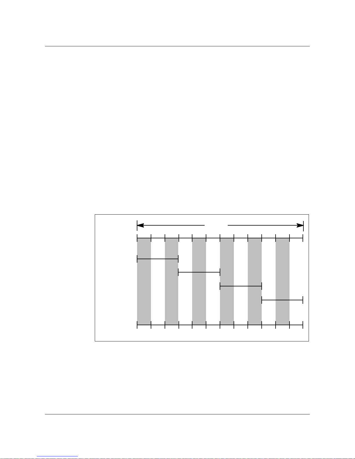
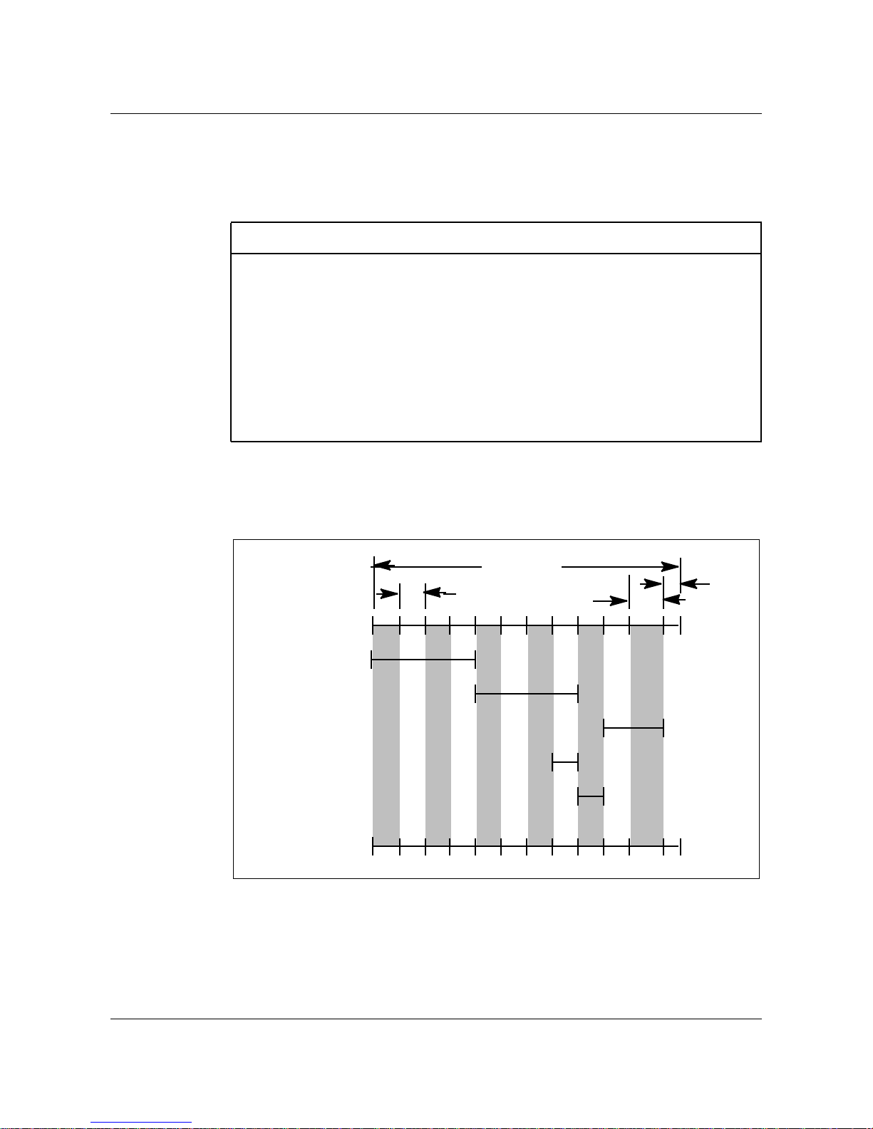
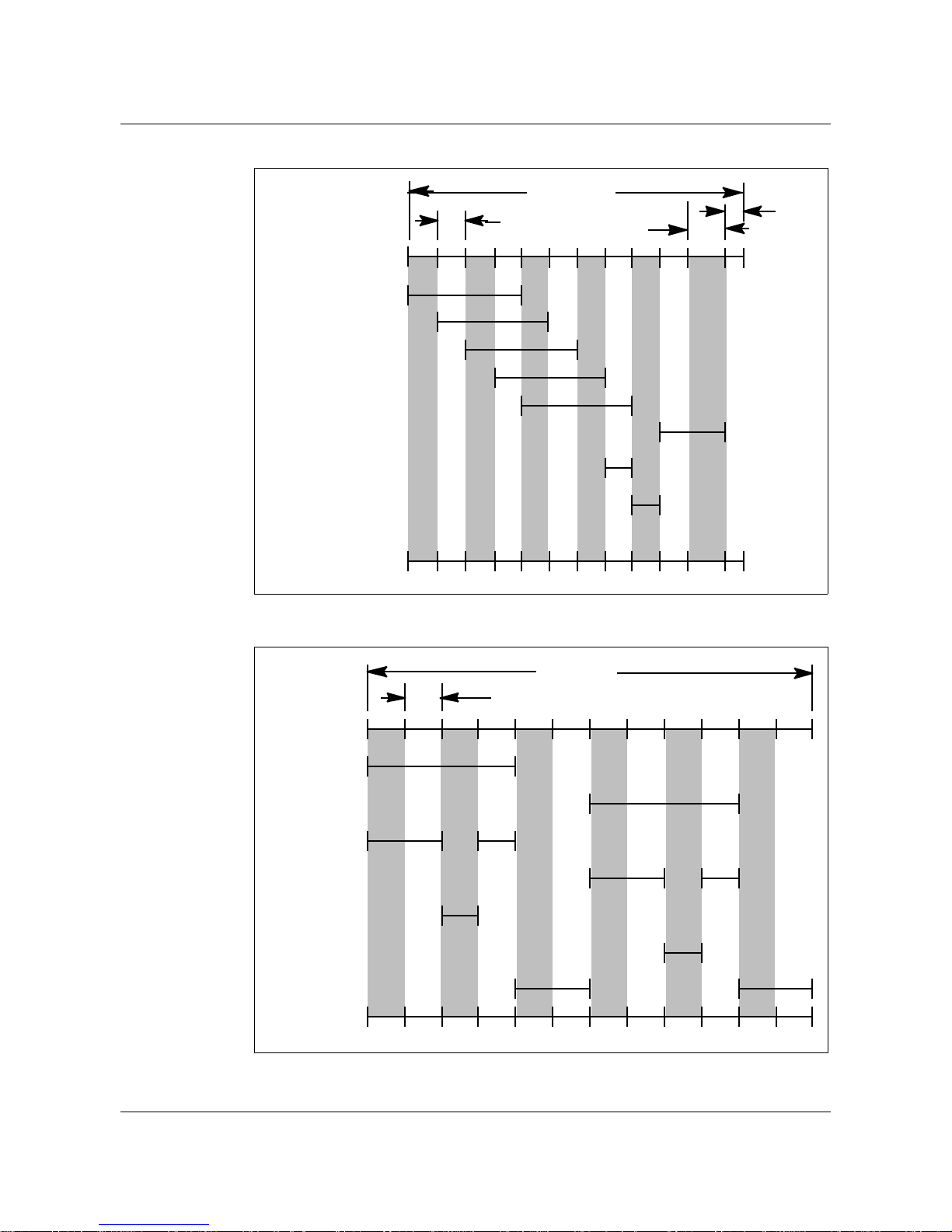
The DMS-100 ringing signal is based on a 6-second (s) cycle. The cycle is
dividedinto 12time slots,which are thesmallest divisions ofthe ringingcycle.
The duration of each timeslot is software controlled and is typically set to0.5
s. In many DMS-100 peripherals, the ringing cycle is further divided into
larger divisions consisting of one or more time slots.
The DMS-100 line module equipment (LME), line concentrating equipment
(LCE), and Subscriber Carrier Module (SCM) each use a distinctive ringing
cycle format. For example, each subdivides the ringing cycle differently.
1-1
The ringing cycle in the LMEis divided into12 time slots, which aretypically
set to 0.5 s each. The ringing cycle in the Line Concentrating Module (LCM),
like the LME, is also divided into 12 time slots. However, the LCM ringing
cycle is further divided into four subcycles. The subcycles consist of one or
more time slots.
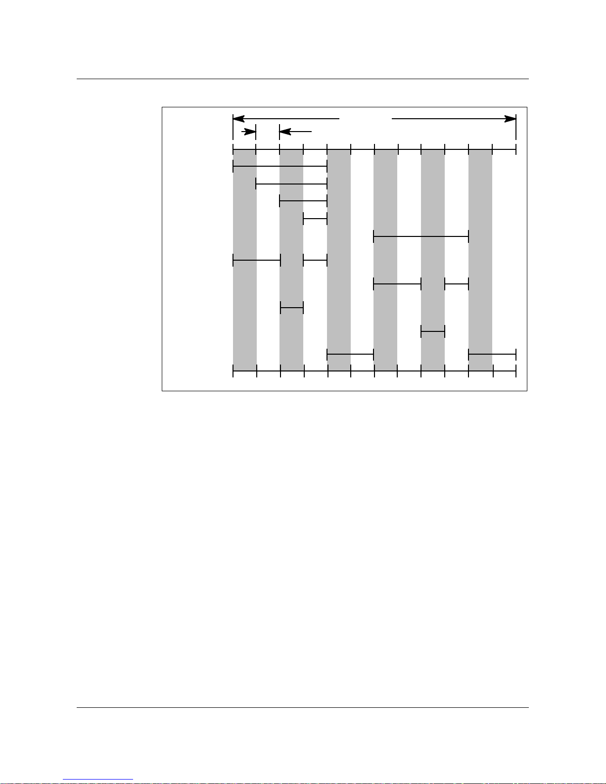
The ringing cyclein the SCM, like theLME and LCM, is dividedinto 12 time
slots. It is further subdivided into three phases consisting of four time slots of
2 s each.
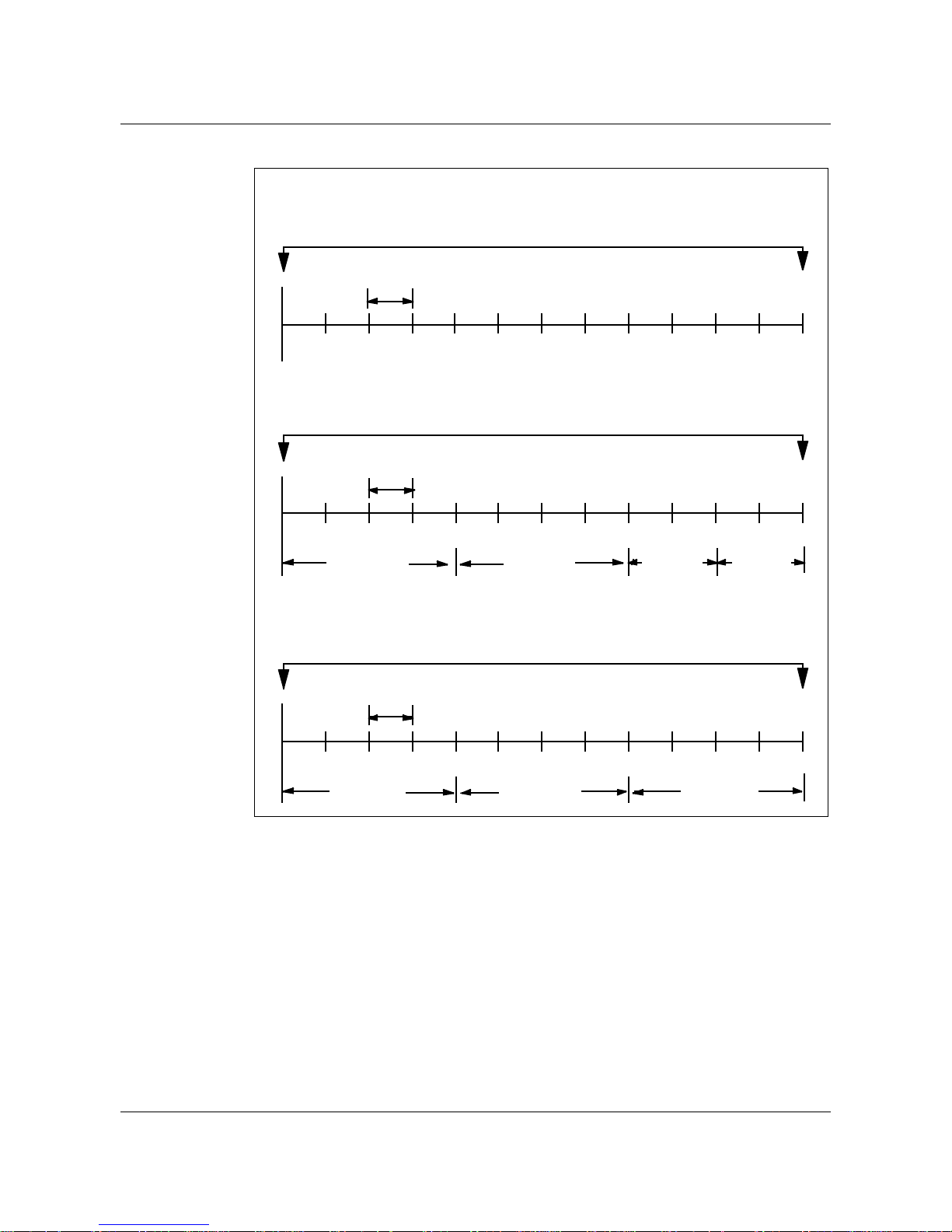
A diagram of each of the DMS-100 ringing cycle formats is shown in the
following figure.
DMS-100 Family DMS-100 Ringing System BASE15 and up
1-2 DMS-100 ringing overview
Figure 1-1 Illustration of a DMS-100 ringing cycle
(500 milliseconds[ms])
LME ringing cycle
Ringing cycle
(6 s)
Time slot
0
12
Time slot
(500 ms)
0
12
Subcycle
0123
Time slot
(500 ms)
0
12
Phase 1 Phase 2 Phase 3
34 5 6 7 891011
LCE ringing cycle
Ringing cycle
(6 s)
3456 7891011
Subcycle Subcycle Subcycle
SCM ringing cycle
Ringing cycle
(6 s)
3456 7 891011
Note: The time slot duration for LCE ringing varies with the ringing
scheme. If ringing issuperimposed or coded, all time slot durations are500
ms. If frequency selective ringing (FSR) is used, time slot 0 is 60 ms, time
slot 1 is 65 ms, time slot 2 is 75 ms, and the remainder of the time slots are
45 ms each. The total duration for the ringing cycle remains 6 s.
Operating company personnel can define the time slot and subcycle durations
according to the type of ringing scheme being used.
Normal and immediate ringing
The DMS-100 switch applies power ringing to a line in either normal or
immediate ringing mode. In the normal ringing mode, the DMS-100 switch
297-1001-131 Standard 06.01 October 2000

DMS-100 ringing overview 1-3
applies power ringing at the start of the next available ringing cycle. If power
ringing can not be applied during the first time slot of a ringing cycle, the
DMS-100 switch will try to schedule power ringing during the first time slot
of the next ringing cycle. This can cause delays in power ringing of up to 6 s
in LCMs and up to 8 s in line modules (LM). To reduce these delays, an
immediate ringing mode is available.
In the immediate ringing mode, the DMS-100 switch applies power ringing
during the next available time slot of the ringing portion of the ringing cycle.
If power ringing cannot be applied during the first time slot of the ringing
portion of a ringing cycle, the DMS-100 switch will try to schedule power
ringing during the next time slot of the ringing portion of the same ringing
cycle. The DMS-100 switch attempts to schedule power ringing during each
time slot of the ringing portion of a ringing cycle until power ringing can be
applied, or the ringing portion of the ringing cycle expires. If power ringing
can not be applied during this ringing cycle, the DMS-100 will try the next
ringing cycle.
Immediate ringing is enabled or disabled by office parameter
IMMEDIATE_RING_ENABLE in table OFCENG.
Note: When changing the office parameter
IMMEDIATE_RING_ENABLEin tableOFCENG toY, considerationmust
be given to the value datafilled for office parameter
ALLOW_RINGING_ON_TIP_SIDE. When this office parameter is set to
Y, a considerable amount of ring slots are reserved for tip side ringing
functionality. This may delay the next available time slot in the ringing
portion of the ring cycle. For more information on office parameter
ALLOW_RINGING_ON_TIP_SIDE,refer to OfficeParametersReference
Manual.
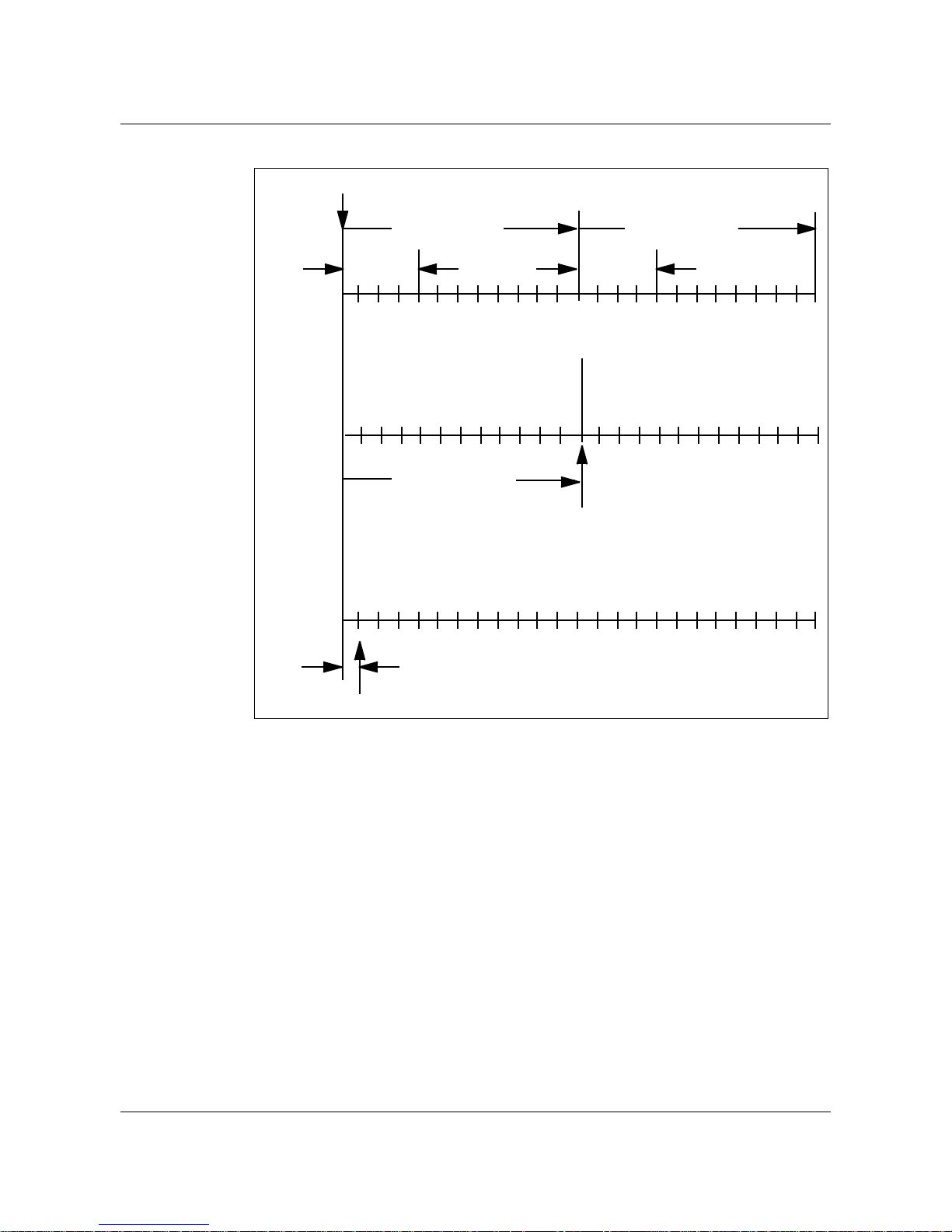
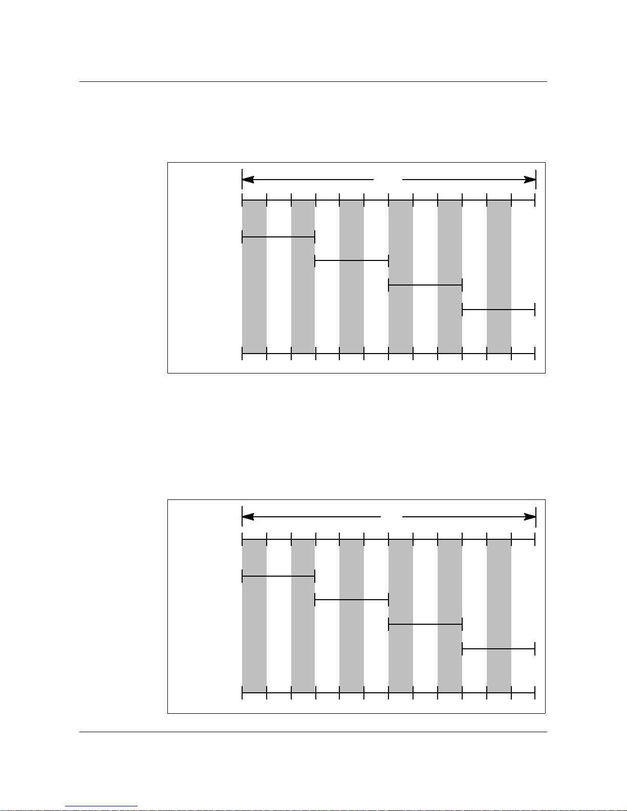
An illustration of normal and immediate ringing for a 1FR (1 flat rate is a
standard line option) is shown in the following figure. This illustration is not
specific to any ringing type. It illustrates the differences in normal and
immediate ringing on a 1FR line when time slot 0 of the ringing cycle is
unavailable.
DMS-100 Family DMS-100 Ringing System BASE15 and up
1-4 DMS-100 ringing overview
Figure 1-2 Normal versus immediate ringing on 1FR line
Ringing request received
Ringing cycle 1 Ringing cycle 2
Normal
ringing
(immediate
ringing
disabled)
Immediate
ringing
enabled
Apply power ringing
01 2 3 4 5 7 86 9 1011 0 1 2 3 4 5 7 86 9 1011
Ringing
applied
12345 786 9 10 11 0 1 2 3 4 5 7 86 9 10110
Time slot 0 not available.
Try cycle 2.
12345 786 9 10 11 0 1 2 3 4 5 7 86 9 10110
6-s delay
Apply power ringing
Time slot 0 not available. Try time slot 1. Time slot 1
available. Apply power ringing at slot 1.
0.5-s delay
Ringing
applied
Time slot 0 available. Apply
power ringing at Time slot 0.
The effects of immediate ringing on the power ringing signal differ between
LME and LCE. In LME, when immediate ringing is enabled, the DMS-100
schedules power ringing during the next available time slot in the ringing
portion of theringing cycle. Ringing is removed at the endof the last time slot
in the ringing portion of the ringing cycle.
For example, in Figure 1-2, "Normal versus immediate ringing on 1FR
line." immediate ringing is enabled on the LME, the first power ringing burst
applies at the start of time slot 1 and continues to the end of time slot 3. This
results in a ringing burst truncated to 1.5 s rather than a complete 2-s burst.
In LCE, like LME, when immediate ringing is enabled, the DMS-100
schedules power ringing during the next available time slot in the ringing
portion of the ringing cycle. Ringing is removed when the 2-s burst has
completed.
297-1001-131 Standard 06.01 October 2000

For example, in the following figure, ringing is enabled on the LCE, the first
ringing burstapplies at thebeginning of time slot1 and continuesto the end of
time slot 4. The initial ringing burst is 2 s.
ANI and coin functions
The DMS-100 ringing bus also providesvoltages for ANI and coin functions.
The ANI and coin voltages include:
• +48 V
• -48 V
• +130 V
• -130 V
Types of ringing
The DMS-100 switch supports the following types of ringing:
• frequency selective ringing
• superimposed ringing
• coded ringing
DMS-100 ringing overview 1-5
• distinctive ringing
• teen ringing
• Japan ringing
Each ringing type is described in the paragraphs that follow.
Frequency selective ringing
Frequency selective ringing is used for service to single party, 2-party, and
multiparty up to eight parties. In the frequency selective scheme, each ringer
on theline is tuned toa specific ringing signalfrequency.When a subscriber is
called, the DMS-100 switch applies to the line the ringing signal where the
called subscriber's ringer is tuned. The called subscriber's ringer, which is
tuned to the applied ringing signal, rings. The remaining ringers on the line,
which are not tuned to the applied ringing signal, reject the ringing signal and
remain silent.
Note: Revertive ringing is not supported for FSR lines.
Revertive calls from FSR lines are permitted. The originator of the revertive
call receivesa treatment, either a tone or an announcement, indicating thecall
is placedto another partyon the same line.The terminating partyalso receives
a treatment. When both parties are off-hook, the talk path is established.
DMS-100 Family DMS-100 Ringing System BASE15 and up
1-6 DMS-100 ringing overview
The treatments for FSR revertive calls are defined in table TMTCNTL,
subtable LNT, in the following tuples:
• originator revertive multiparty frequency with three or more parties
(ORMF)
• originator revertive frequency with two parties (ORAF)
• terminating party (TRRF)
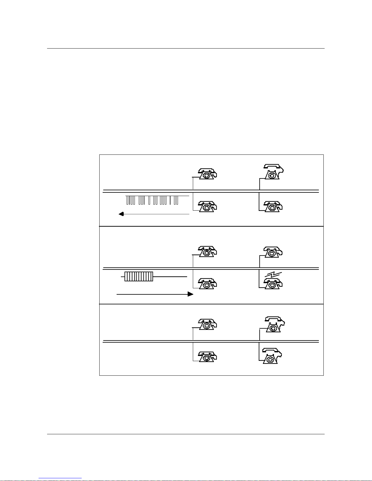
The following figure illustrates the sequence of events that occur when a
revertive call is made on a multiparty, FSR line.
Figure 1-3 Revertive call on multiparty, FSR line
1. Calling party (party 2) goes off-hook, dials called number, receives fast
busy,then hangs up.
Tip
Ring
Dial pulses
Party 1
Party 3
fR=20Hz
(see note 1)
fR=20Hz
Party 2
fR=30 Hz
fR=30 Hz
Party 4
2. The called party (party 4) receives 30 Hz ringing signal.
fR=20Hz
Tip
Ring
30 Hz
Ringing signal
3. When called party answers, the call enters the talking state.
Tip
Ring
Party 1
Party 3
Party 1
Party 3
fR=20Hz
fR=20Hz
(see note 1)
fR=20Hz
Party 2
Party 4
Party 2
Party 4
fR=30 Hz
fR=30 Hz
fR=30 Hz
fR=30 Hz
Note 1: fR indicates the ringer's tuned frequency.
Note 2: The previous diagram does not show the ground connection of the
tip and ring ringing circuits. These grounds are provided at the subscriber's
location.
297-1001-131 Standard 06.01 October 2000
DMS-100 ringing overview 1-7
The frequencies usedinthe frequency selectiveringing scheme are as follows:
• harmonic ringing: 16-2/3 Hz, 25 Hz, 33-1/3 Hz, 50 Hz, 66-2/3 Hz
• synchromonic ringing (20 Hz base): 20 Hz, 30 Hz, 42 Hz, 54 Hz, 66 Hz
• synchromonic ringing (16 Hz base): 16-2/3 Hz, 30 Hz, 42 Hz, 54 Hz
• decimonic ringing: 20 Hz, 30 Hz, 40 Hz, 50 Hz, 60 Hz.
Frequency selective ringing is used by Rural Electrification Association
(REA) offices. The following figures illustrate the REA frequency selective
ringing timing for the following types of ringing:
• synchromonic
• harmonic
• decimonic
Synchromonic ringing
The following figure illustrates the relationship between the synchromonic
ringing signals and the DMS-100 ringing cycle.
Figure 1-4 Synchromonic ringing
6s
02345786101119
FrequencyA
(1 party)
FrequencyB
FrequencyC
FrequencyD
ANI/coin
3300HHzz
11..9955ss
(seenote)
(Any available slot)
02345786101119
4422HHzz
11..3355ss
5544HHzz
11..3355ss
6666HHzz
11..3355ss
Note: Available frequenciesare 16-2/3 Hz,20 Hz, 30Hz, 42 Hz,54 Hz and
66 Hz. Any four of the available six frequencies, in any order, can be
assigned to frequencies A through D: however, 16 Hz and 20 Hz can not be
used simultaneously.
DMS-100 Family DMS-100 Ringing System BASE15 and up
1-8 DMS-100 ringing overview
Harmonic ringing
Thefollowing figureillustrates therelationshipof theharmonic ringingsignals
with the ringing cycle.
Figure 1-5 Harmonic ringing
6s
02345786101119
FrequencyA
(1 party)
FrequencyB
FrequencyC
FrequencyD
ANI/coin
2255HHzz
11..9955ss
(seenote)
(Any available slot)
02345786101119
3333----11//33HHzz
11..3355ss
5500HHzz
11..3355ss
6666----22//33HHzz
11..3355ss
Note: Available frequencies are16-2/3, 25, 33-1/3,50, and 66-2/3 Hz.Any
four of these, in any order, can be assigned to frequencies A through D.
Decimonic ringing
Thefollowing figureillustrates therelationship betweenthe decimonicringing
signals and the ringing cycle.
Figure 1-6 Decimonic ringing
6s
FrequencyA
(1 party)
FrequencyB
FrequencyC
FrequencyD
ANI/coin
297-1001-131 Standard 06.01 October 2000
02345786101119
3300HHzz
11..9955ss
(seenote)
(Any available slot)
02345786101119
4400HHzz
11..3355ss
5500HHzz
11..3355ss
6600HHzz
11..3355ss
Note: Available frequencies are 20 Hz, 30 Hz, 40 Hz, 50 Hz, and 60 Hz.
Any fourofthese, in any order, can be assignedto frequencies A through D.
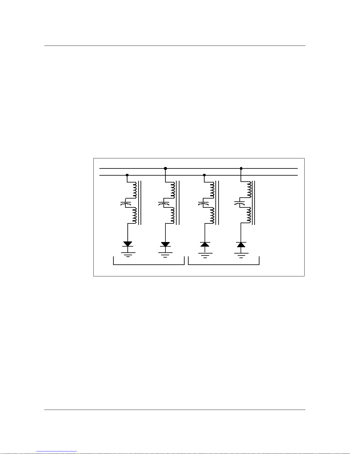
Superimposed ringing
Superimposed ringing is a form of selective ringing which uses a positive or
negativebiased 20 Hzringing signal andpolarizing devices,such as gas tubes,
at the receiving end for full or semi-ringer selection. In the fully selective
configuration, a maximum of four parties can be connected to one line, with
two on the tip side and two on the ring side.
Theringer connectionsof thefully selectiveringing schemeis illustratedin the
following figure.
Figure 1-7 Fully selective ringer configuration - superimposed ringing
Tip
Ring
DMS-100 ringing overview 1-9
Ringer 2 Ringer 4Ringer 1 Ringer 3
Negative-biasedringersPositive-biasedringers
On both the tip and ring side, the ringer of one party is polarized for a
positive-biased ringing signal, while the ringer of the other party is polarized
for a negative-biased signal.A positive-biased ringingsignal applied to the tip
side, for example, rings only the party on the tip side with the positive-biased
ringer.
In the semi-selective configuration, a maximum of eight parties can be
connected to one line, with four on the tip side and four on the ring side. On
each side, two ringers are polarized for a positive-biased ringing signal, while
the other two are polarized for a negative-biased ringing signal. A
positive-biased ringing signal applied to the tip side, for example, in the
semi-selective configuration, rings only the two parties with ringers polarized
for a positive ringing signal. Becausetwo parties ring simultaneously, a single
ring (code 1) and a 2-ring (code 2) ringing scheme is used to distinguish
between the two parties.
DMS-100 Family DMS-100 Ringing System BASE15 and up

1-10 DMS-100 ringing overview
Revertive calls (calls from a subscriber on a multiparty line to another
subscriber on the same party line) are permitted in the superimposed scheme.
The callingparty receives revertiveringing while thecalled partyis being rung
if the callingparty is on theopposite side, tip or ring,of the called party, or the
calling party is on the same side but with the opposite polarity of the called
party.
If the calling party is on the same side with the same polarity as the called
party, the calling party, after going on-hook, is rung simultaneously with the
called party.
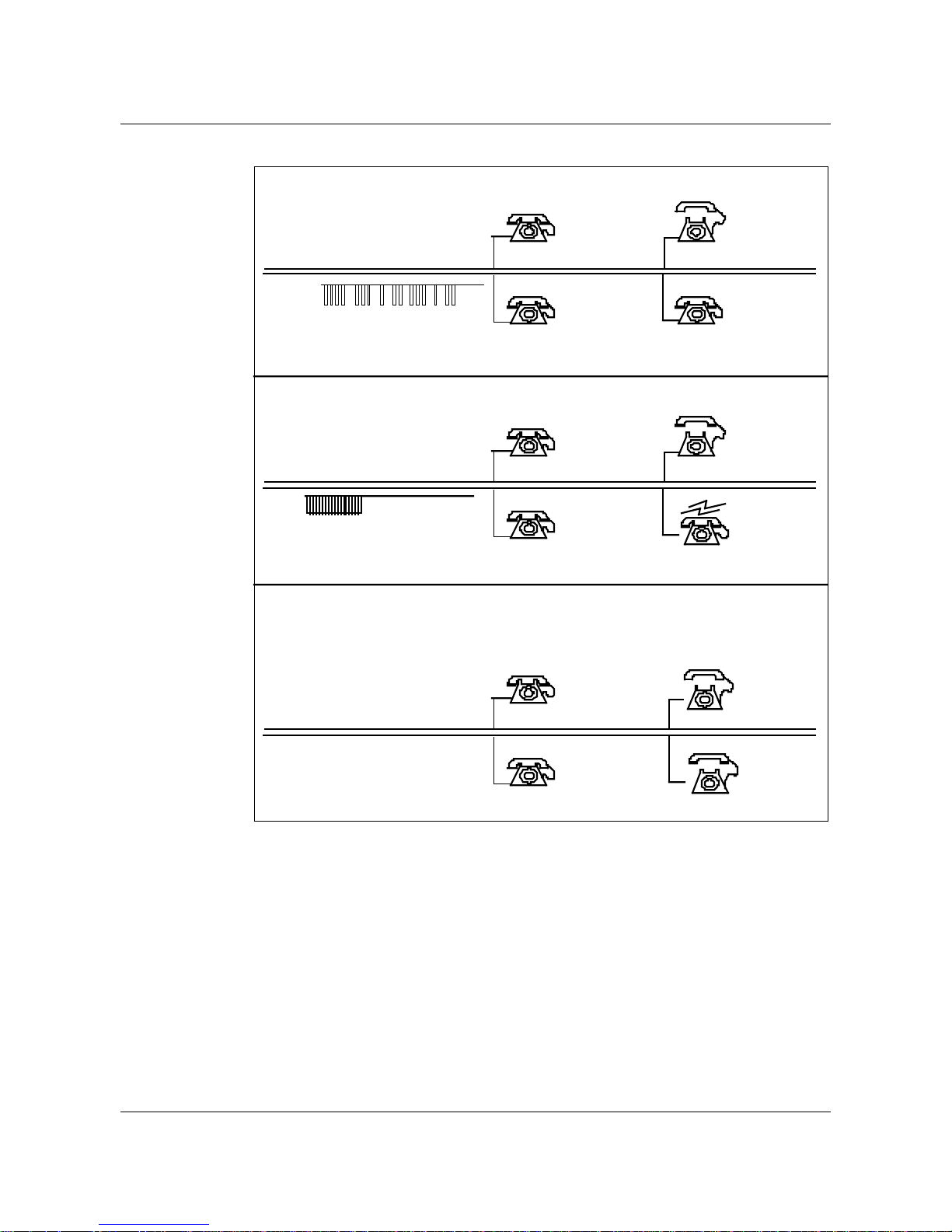
The following figure illustrates a call being placed from the tip side of a
multiparty, superimposed ringing line to a party on the ring side of the same
line with a negatively-biased ringer.
297-1001-131 Standard 06.01 October 2000
DMS-100 ringing overview 1-11
Figure 1-8 Call on multiparty superimposed ringing line
1. Calling party (party 2) goes off-hook and dials called party (party 4).
Tip
Party 1
+R
(see note 1)
Party 2
--R
Ring
Party 3
+R
Party 4
--R
2. The called party (party 4) receives negative-biased ringing signal.
Tip
Party 1
+R
Party 2
--R
Ring
Party 3
+R
Party 4
--R
3. When called party answers, revertive ring on calling party's side ceases,
indicating to the calling party that the called party has answered. Calling
party then goes off-hook and the call enters the talking
state.
+R
Tip
Party 1
Party 2
Ring
+R
Note 1:
Party 3
+R indicates positive-biased ringers and -R indicates negative biased
Party 4
ringers.
Note 2:
This diagram does not show the ground connections of the tip and ring
circuits. These grounds are provided at the subscriber's location.
DMS-100 Family DMS-100 Ringing System BASE15 and up
--R
--R
1-12 DMS-100 ringing overview
The dc component of the superimposed ringing signal determines the ringer
selection.The followingtable liststhe valuesof boththe acand dccomponents
of the superimposed ringing signals.
Table 1-1 Superimposed ringing signal - ac and dc components>
ac dc Frequency (Hz)
86 -38 20
86 +36 20
86 -52 20
86 +52 20
105 +52 20
105 -52 20
The following figuresillustrate the relationshipbetween the ringingsignal and
the DMS-100 ringing cycle.
Figure 1-9 LCE superimposed revertive ringing with no immediate ring
6s
Even LSGs 1, 2
party
Odd LSGs 1, 2
party
3, 4 party
Negativerevertive
splash
Positive revertive
splash
ANI/coin (Any available slot)
01
0.46 s
2345 78610119
2345 7861011901
0.92 s
0.48 s
297-1001-131 Standard 06.01 October 2000
DMS-100 ringing overview 1-13
Figure 1-10 LCE superimposed revertive ringing with immediate ring enabled
6s
0.46 s
0.92 s
0.48 s
01
2345 78610119
Even LSGs
1, 2 party
3, 4 party
Negativerevertive
splash
Positive revertive
splash
(Any available slot)ANI/coin
2345 7861011901
Figure 1-11 LCE superimposed revertive ringing with no immediate ring
6s
0.5 s
--48V1FR,
2FR code 1
+48V 2FR
code 1
--48Vmulti-
party code 2
+48V multi
party code 2
Revertive
splash --48V
Revertive
splash +48V
ANI/coin
02345786101119
02345786101119
DMS-100 Family DMS-100 Ringing System BASE15 and up
1-14 DMS-100 ringing overview
Figure 1-12 LCE superimposed revertive ringing with immediate ring enable
6s
0.5 s
--48V2FR
code 1
+48V 2FR
code 1
--48Vmulti-
party code 2
+48V multi-
party code 2
Revertive
splash --48V
Revertive
splash +48V
ANI/coin
02345786101119
02345786101119
For the LCMof the LCE frame/cabinet with coded immediate ringing andthe
central control (CC) Patch TLA67, power ringing will be applied within 0.5 s
of the start ring back illustrated in the following figure.
297-1001-131 Standard 06.01 October 2000
 Loading...