

Page 1
Enterprise Policy Manager - Device Management Guide
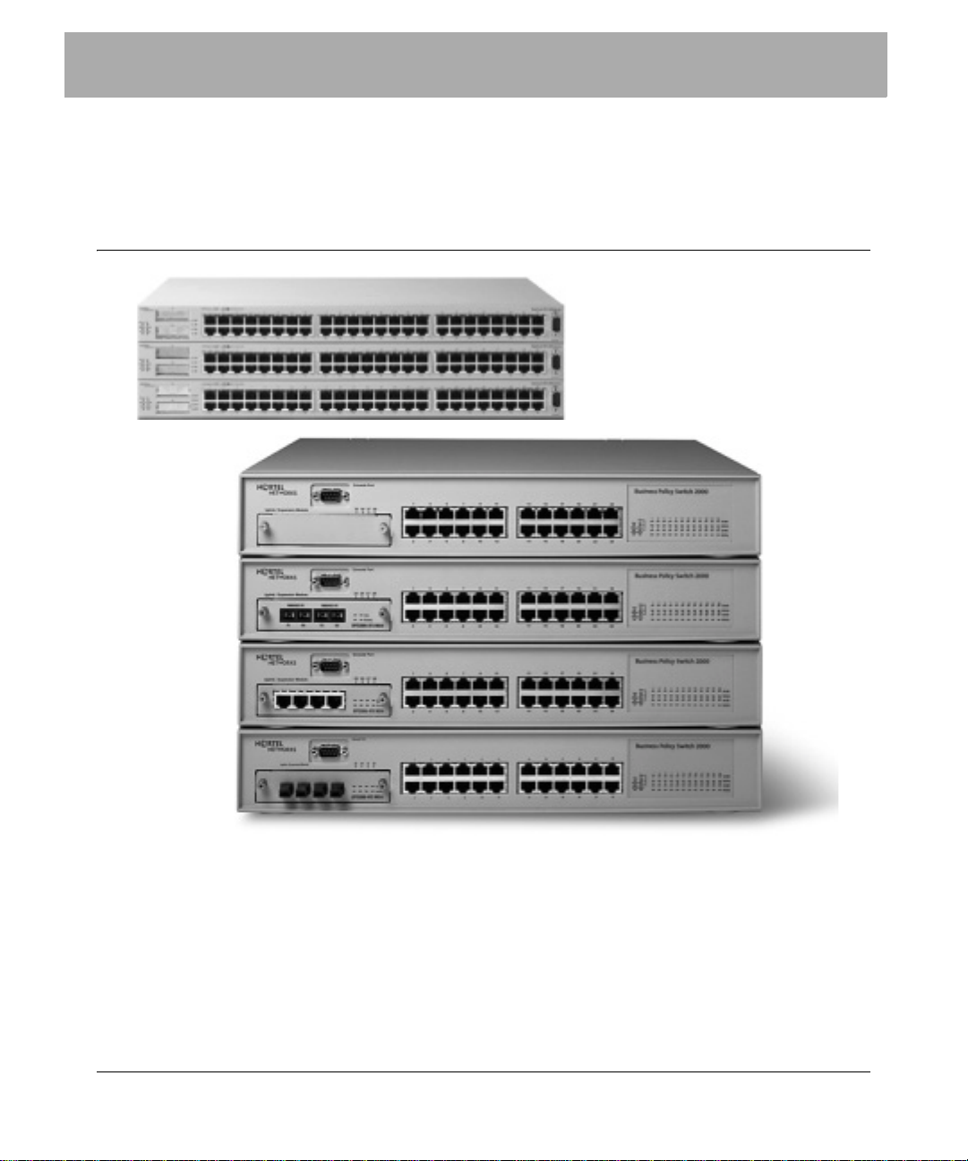
Policy management on the Nortel Ethernet Switch
460, Ethernet Switch 470, and BPS
This guide contains information relating to the configuration of the Nortel
Ethernet Switch 460 (formerly BayStack 460), Ethernet Switch 470 (formerly
BayStack 470), and Business Policy Switch (BPS), to receive policy configuration
from Nortel Enterprise Policy Manager (EPM). It also includes information on the
devices’ compatibility with various policy management objects.
This guide covers the following subjects:
Page 2

2 Policy management on the Nortel Ethernet Switch 460, Ethernet Switch 470, and BPS
• “Nortel product rebranding” on page 2
• “Nortel product rebranding” on page 2
• “Configuring the device for policy management” on page 3
• “Testing an Ethernet Switch or BPS device’s policy configuration” on page 5
• “Known device limitations for EPM 4.1” on page 6
• “Policy object - device compatibility” on page 7
• “EPM access requirements” on page 8
• “Hardware changes on a policy-enabled device” on page 9
• “Accessing device documentation” on page 9
• “BPS action limitations” on page 10
Nortel product rebranding
Nortel transitioned to new names for many of its products over the course of 2004.
The transition simplifies product naming in order to make it easier for customers
to understand the Nortel product and services portfolio. Table 1 lists the names of
rebranded Nortel products mentioned in this publication.
Table 1 Nortel product rebranding
Products formerly knowm as.... New Nortel Name
Optivity Policy Services (OPS) Nortel Enterprise Policy Manager (EPM)
BayStack Nortel Ethernet Switch
Full details of the Nortel product rebranding process can be obtained from
http://www.nortel.com/products/announcements/rebranding/index.html#faqs.
Supported software
The EPM 4.1 release has been tested to support the BoSS 3.0, 3.1 software, as
well as the BPS version 2.5 software. BoSS 3.1.1 software is required to support
UBP functionality. EPM 4.1 has been tested to support BoSS 3.6 for the Ethernet
Switch 460 and Ethernet Switch 470.
318396-4.1
Page 3

Policy management on the Nortel Ethernet Switch 460, Ethernet Switch 470, and BPS 3
If you are working with a maintenance release in the EPM 4-series (i.e. post-4.1),
it may have been tested against a newer version of the device software. To verify
the absolute latest supported device software versions, refer to the Release Notes
for Enterprise Policy Manager manual.
Configuring the device for policy management
In order for an Ethernet Switch 460, Ethernet Switch 470, or Business Policy
Switch unit to receive policy configuration from EPM, the devices themselves
must be configured to communicate with the EPM Policy Server. Detailed
instructions for accomplishing this task are included below. Once this is
completed, the devices will report to the EPM Policy Server and they will appear
as icons in the management console. The roles they report are also displayed.
Policy management can be initiated by associating a policy with the device’s
reported role(s).
You must open the Web interface for the device and specify the address and port
number of the EPM Policy Server. You can specify more than one Policy Server.
You must also enable QoS configuration on the device and define its role
combinations.
You must know the IP address and COPS-PR Client Port values for your Policy
Server. You can obtain these values by right-clicking the Policy Server object in
the EPM management console and choosing Properties from the menu.
To configure an Ethernet Switch or BPS unit to accept policy configuration,
follow these steps:
1 Launch the Web interface for the device you want to configure. Open a Web
browser and go to the IP address of the device.
2 In the Access list, navigate to the following location:
Application > COPS > Configuration
3 In the COPS Client Creation area, do the following:
a Type the IP address of your EPM Policy Server in the IP Address field.
b Type the Policy Server COPS-PR Client Port number (specified in EPM)
in the TCP Port field. The default value for this field is 3288.
Page 4

4 Policy management on the Nortel Ethernet Switch 460, Ethernet Switch 470, and BPS
c Type a priority value in the Priority field.
If you are specifying more than one Policy Server, the priority value sets
the sequential order in which the client connects to the Policy Servers.
d Click the Submit button below the COPS Client Creation area.
An entry for the Policy Server is added to the COPS Configuration Table.
e Repeat steps a through d to specify additional Policy Servers (if required).
4 In the Access list navigate to the following location:
Application > QoS > QoS Advanced > Agent
5 In the QoS Configuration area, choose the Enabled option from the QoS
Policy Server Control drop-down list.
6 Click the Submit button.
7 In the Access list navigate to the following location:
Application > QoS > QoS Advanced > Devices > Interface Config
8 In the Interface Group Creation area, do the following:
a T ype a name for a role combination in the Role Combination field. Do not
use spaces in role combination names.
318396-4.1
The role combination is a common identifier that is used to enforce a
specific set of policies on specific network entities (for example, the print
server, the Web server, employee workstations, etc.). EPM includes a set
of preconfigured roles with policy objects linked to them. You can use
these roles for test purposes. To find the names of these roles, open the
Policy Setup view of the EPM management console.
b Choose an interface class from the Interface Class drop-down list.
Your choice of Trusted, Untrusted, or Unrestricted will depend on the
type of policy actions that will be enforced on the network traffic
controlled under the role combination.
c Click the Submit button below the Group Creation area.
The new interface group is added to the Interface Group table.
d Click the Edit button next to the new entry in the Interface Group table.
The QoS - Interface Group Port Assignment dialog box appears.
Page 5

Policy management on the Nortel Ethernet Switch 460, Ethernet Switch 470, and BPS 5
e Enable the check box for each port on the device that you want to include
under the new role combination, and then click the Submit button.
f Repeat steps a through e to define additional role combinations.
9 Exit the device’s Web interface.
Testing an Ethernet Switch or BPS device’s policy configuration
In order to check the policy filters installed on your COPS-PR devices, you must
meet the following requirements:
• You must hav e SNMP reporting enabled on your network devices.
• You must enter the SNMP string for each device on the device’s
corresponding object in the EPM management console.
• You must have the EMANATE SNMP master agent (available as a default
EPM installation option) installed with your Policy Server.
1 In the Policy Setup view , drag a policy from the Available Policy Components
tree to the role that is being reported by the device. Enable the policy from the
Options menu.
For example, you can choose the Mark WWW Traffic Best Effort During
Lunch policy to match all Web traffic between 11:30 am and 1:30 pm. You
can remove the schedule from the policy to make it active all of the time.
2 Click the Deploy Changes button on the toolbar to notify the Policy Server of
your changes.
3 In the Device Setup view, right-click on the device and choose Show Device
Report from the menu.
4 In the Device Report dialog box, click the Lookup button next to the Interface
field and choose the interface for which you want to view installed policy
filters.
If the policy was correctly installed on the device, a list of traffic filters
generated by the policy appears in the Filter Set list. If any traffic matching
the filters has passed through the device, the number of affected packets
appears under the Packets column for each filter.
Page 6

6 Policy management on the Nortel Ethernet Switch 460, Ethernet Switch 470, and BPS
Known device limitations for EPM 4.1
Users should consider the following guidelines when creating policy
configuration for the BPS or Ethernet Switch devices.
• If you are running a stack of cascaded Ethernet Switch devices, you can
configure user-based policies on the stack ONLY if the stack consists entirely
of COPS-PR compatible devices (Business Policy Switch, Ethernet Switch
460, and Ethernet Switch 470). If you are running a mixed stack that includes
Ethernet Switch 450 devices, you will not be able to configure user-based
policies on the stack.
• Maximum 24 roles per device.
• Maximum 200 IP traffic conditions per device.
• Maximum 14 802 traffic conditions per device.
• Devices with limited memory may not be able to achieve the limitations
stated above.
• The BPS 2.x series has a special limit of 24 traffic conditions that specify the
same source IP address.
To avoid device limitations
318396-4.1
• Avoid assigning multiple traffic conditions with overlapping traffic criteria to
a single policy. This will result in excessive numbers of policy filters being
sent to the device. For example, do not assign two traffic conditions, each
specifying the same port number, to the same policy.
• When creating a traffic condition, you should limit the number of different
types of traffic flow criteria you specify. A traffic condition that specifies too
many traffic criteria will, in turn, cause the policies to which it is applied to
send an excessive number of policy filters to network devices. The network
devices may return error messages as a result.
Page 7
Policy management on the Nortel Ethernet Switch 460, Ethernet Switch 470, and BPS 7
Policy object - device compatibility
EPM provides a selection of policy-related objects (traffic conditions and actions)
to support traffic matching and traffic conditioning on a number of policy-enabled
network devices. This does not mean that all of the devices supported by EPM
will support all of the policy objects provided by EPM. This section lists the
traffic criteria matching and policy action types supported by BayRS devices.
Note: The information displayed here reflects the most up-to-date
information available at the time of the EPM 4.1 release. Policy filter
support capabilities may change for individual device types as their
software is upgraded. Check your device documentation for current
policy support capabilities.
Filtering capability Ether Type
VLAN ID
Inbound User Priority
Protocol
Inbound DSCP
Port Ranges
Src/Dest Address and Mask
Src/Dest Port
Policy priority support
(filter prioritization)
DiffServ action capability Mark DSCP
Shaping support (Yes)
COPS-PR capability Configure Roles on Device
(Yes)
Forward
Drop
Meter (2 Level)
Mark User Priority (L2)
Mark Drop Precedence (L2)
Configure Backup PDP on Device
Page 8

8 Policy management on the Nortel Ethernet Switch 460, Ethernet Switch 470, and BPS
Reporting capability Device Reporting - View Filters (via SNMP)
Device Reporting - Filter Statistics (via SNMP)
Queue mapping capability 802 COS to DSCP
DSCP to 802 COS
DSCP to queue
802 COS to queue
EPM access requirements
In order for EPM to be able to send policy configuration to your networking
devices, COPS-PR, SNMP and Telnet connections must be permitted on your
devices. The following protocols and port numbers are required for
communication between the various components of the EPM product family and
your networking devices:
• The management console uses LDAP (port 389 default) to communicate with
the directory server. It uses SNMP to communicate with Policy Servers and
networking devices. Remote access to the directory requires HTTP (port 80
default).
• The Policy Server uses LDAP (port 389 default) to communicate with the
directory server. It uses COPS-PR (port 3288 default) and SNMP (ports 161
and 162) to communicate with networking devices and the Interface Manager.
• The Interface Manager uses LDAP (port 389 default) to communicate with
the directory server. It uses COPS-PR (port 3288 default) to communicate
with the Policy Server, and uses Telnet (port 23) to communicate with
networking devices.
318396-4.1
The LDAP, HTTP, and COPS-PR port numbers can be changed.
Page 9

Policy management on the Nortel Ethernet Switch 460, Ethernet Switch 470, and BPS 9
Hardware changes on a policy-enabled device
Making hardware changes to a device that is enabled for policy management (for
example, switching off and changing blades) will cause the Policy Server to
generate errors when the device is disconnected. To avoid these errors, disable the
device for policy management through EPM before making the hardware
changes. After you have completed the hardware changes and reconfigured the
device, you can re-enable the device for policy management.
➨ To disable a device for policy management, right-click its object in the EPM
management console and then choose Disable For Policy Management from
the menu.
➨ To enable a device for policy management, right-click its object in the EPM
management console and then choose Enable For Policy Management from
the menu.
Fixed device reset issue
(Q01038174) BoSS version 3.1.3 had a problem that caused the device to reset
repeatedly when running QoS with OPS (EPM). Fixed in BoSS 3.1.4.2.
Accessing device documentation
A complete set of documentation for the Ethernet Switch and BPS devices,
including configuration manuals, user manuals, release notes, and known
anomalies, are available on the Nortel Networks web site at:
http://www.nortelnetworks.com
Follow the link for Technical Documentation and then choose a device as the
product family.
Page 10

10 Policy management on the Nortel Ethernet Switch 460, Ethernet Switch 470, and BPS
BPS action limitations
The Business Policy Switch (BPS) accepts different types of policy actions,
depending on the software version installed on the device. In some cases, the EPM
Policy Server does not send all of the action types accepted by the BPS. Use this
appendix as a reference when assigning actions to policies intended for BPS units.
Your choice of action depends on the port class, as de fined on the BPS:
• Trusted ports assume that all traffic coming into the port is originating from
a trusted source. Therefore, the DSCP field of any traffic that enters the BPS
from a trusted port is never re-marked. Any policies instructing the BPS to set
the value of the DSCP field on a trusted port will generate errors. Only
policies with Drop or Forward actions are permitted on trusted ports.
• Untrusted ports assume that all traffic coming into the port is suspect.
Therefore, the DSCP field of any traf fic that enters the BPS from an untrusted
port is always re-marked. Any policies instructing the BPS to not set the value
of the DSCP field on an untrusted port will generate errors. Only policies with
Meter, Mark, and Drop actions are permitted on untrusted ports.
• Unrestricted ports do not assume anything about the origin of the incoming
traffic. You may assign a policy action to re-mark the DSCP or not to re-mark
the DSCP. This allows you to manipulate the DSCP value based upon the
filter criteria, and not upon the point of origin. All policy actions are permitted
on unrestricted ports.
318396-4.1
The following traffic classifications are handled by the BPS:
• Layer 3 - refers to IP filters, or layer 2 filters with IP classification defined in
the ether type value.
• Layer 2 - refers to filters that have no concept of IP.
• Layer 2 (Tagged) - refers to filters that are layer 2 and have the VLAN tag
specified as Tagged Only.
• Layer 2 (UnTagged) - refers to filters that are layer 2 and have the VLAN tag
specified as UnTagged Only.
This section covers the BPS interface class behavior for the following action
types:
Page 11

Policy management on the Nortel Ethernet Switch 460, Ethernet Switch 470, and BPS 11
Update DSCP actions
Table 2 describes the allowable DSCP update actions unde r different interface
classes, relative to BPS software versions and traffic classifications.
Table 2 DSCP Update action behavior
Device softw are
version
Untrusted Trusted Unrestricted
BPS 2.0, 3.0, 3.1
Layer 3 Mark
*
Layer 2
Tagged Ignore
UnTagged Ignore
* Mark - Update DSCP with value 0-63.
† Ignore - Ignore DSCP.
‡ All - All actions allowed.
†
†
Update User Priority actions
Table 3 describes the allowable User Priority Update actions under different
interface classes, relative to BPS software versions and traffic classifications.
Table 3 User Priority Update action behavior (under lined text denotes EPM
default setting, where multiple options exist)
Device softw are
version
Untrusted Trusted Unrestricted
Ignore
Ignore
Ignore
†
†
†
‡
All
Ignore
Ignore
†
†
BPS 2.0, 3.0, 3.1
Layer 3 Update 0-7*,
Defaults
†
Egress Map
‡
Refer to Table 4.
Layer 2
Tagged Update 0
UnTagged Ignore
* Update 0-7 - Update user priority with value of 0-7.
† Defaults - Use COS value from DSCP to COS mapping, based on DSCP value in action.
*
-7
**
Ignore
Ignore
**
**
Update 0-7*, Ignore
Update 0-7*, Ignore
**
**
Page 12

12 Policy management on the Nortel Ethernet Switch 460, Ethernet Switch 470, and BPS
‡ Egress Map - Use COS value from DSCP to COS mapping, based on DSCP from incoming
packet.
** Ignore - Ignore user priority value.
Table 4 describes the allowable User Priority Update actions, based on the DSCP
specification for the same action.
Table 4 Allowable User Priority Update actions (underlined text denotes EPM
default setting, where multiple options exist)
DSCP Ignore DSCP Mark Drop
Update User Priority Update 0-7*, Egress
Map†, Ignore
* Update 0-7 - Update user priority with value 0-7.
† Egress Map - Use COS value from DSCP to COS mapping, based on DSCP from incoming
packet.
‡ Ignore - Ignore user priority.
** Defaults - Use COS value from DSCP to COS mapping, based on DSCP value in action.
‡
Defaults
**
Ignore
‡
Update Drop Precedence actions
318396-4.1
Table 5 describes the allowable Drop Precedence Update actions under different
interface classes, relative to BPS software versions and traffic classifications.
T ab le 5 Drop Precedence Update action beha vior (underline d text denote s EPM
default setting, where multiple options exist)
Device softw are
version
BPS 2.0, 3.0, 3.1
Layer 3 Update 1-8*,
Layer 2
Tagged Update 8
UnTagged Ignore
* Update 1-8 - Update drop precedence with value 1-8.
† Defaults - Use COS value from DSCP to COS mapping, based on DSCP value in action.
Untrusted Trusted Unrestricted
Defaults
†
Update 1-8
**
Egress Map
,
*
Ignore
Ignore
‡
**
**
Refer to Table 6.
Update 1-8*, Ignore
Update 1-8*, Ignore
**
**
Page 13

Policy management on the Nortel Ethernet Switch 460, Ethernet Switch 470, and BPS 13
‡ Egress Map - Use COS value from DSCP to COS mapping, based on DSCP from incoming
packet.
** Ignore - Ignore drop precedence.
Table 6 describes the allowable Drop Precedence Update actions, based on the
DSCP specification for the same action.
Table 6 Allowable Drop Precedence actions (underlined text denote s EPM
default setting, where multiple options exist)
DSCP Ignore DSCP Mark Drop
Update Drop
Precedence
* Update 1-8 - Update drop precedence with value of 1-8.
† Egress Map - Use COS value from DSCP to COS mapping, based on DSCP from incoming
packet.
‡ Ignore - Ignore drop precedence.
** Defaults - Use COS value from DSCP to COS mapping, based on DSCP value in action.
Update 1-8*, Egress
Map†, Ignore
‡
Defaults
**
Ignore
‡
EPM traffic shaping limitations on the Business Policy Switch
The Business Policy Switch (BPS) 2.0 software allows shaping on different types
of policy actions, depending on the traffic type (layer 2 or 3) and the device port
class (as defined on the BPS). In some cases, the EPM Policy Server does not send
all of the action types accepted by the BPS.
Note: You must have the correct MDA module installed on your BPS
units in order for them to accept traffic shaping actions. For more
information, refer to the BPS documentation.
Page 14

14 Policy management on the Nortel Ethernet Switch 460, Ethernet Switch 470, and BPS
In all cases, the 802.1p User Priority value must be known for a flow of packets in
order for shaping to take place. Because packets must be re-marked before the
802.1p User Priority value can be known, Ignore or Drop actions cannot include
shaping functionality. Only Mark actions can include shaping functionality.
Table 7 Shaper limitations on BPS ports
Device softw are
version
BPS 2.0, 3.0, 3.1
Layer 3 Supported with Mark*
Layer 2 Not supported. Not supported. Not supported.
* Mark - Update DSCP with value 0-63.
Untrusted Trusted Unrestricted
action only.
Not supported. Supported with
Mark
*
action only.
318396-4.1
 Loading...