

Page 1

Part No. 320656-A
July 2005
4655 Great America Parkway
Santa Clara, CA 95054
WLAN—Security Switch 2300 Series
Installation and Basic Configuration
Guide
*320655-A*
Page 2

2
Copyright © Nortel Networks Limited 2005. All rights reserved.
The information in this document is subject to change without notice. The statements, configurations, technical data, and
recommendations in this document are believed to be accurate and reliable, but are presented without express or implied
warranty. Users must take full responsibility for their applications of any products specified in this document. The
information in this document is proprietary to Nortel Networks.
Trademarks
*Nortel Networks, the Nortel Networks logo, and the Globemark are trademarks of Nortel Networks.
*Microsoft, MS, MS-DOS, Windows, and Windows NT are registered trademarks of Microsoft Corporation.
*Adobe and Acrobat Reader are trademarks of Adobe Systems Incorporated.
All other trademarks and registered trademarks are the property of their respective owners.
Restricted rights legend
Use, duplication, or disclosure by the United States Government is subject to restrictions as set forth in subparagraph
(c)(1)(ii) of the Rights in Technical Data and Computer Software clause at DFARS 252.227-7013.
Notwithstanding any other license agreement that may pertain to, or accompany the delivery of, this computer software,
the rights of the United States Government regarding its use, reproduction, and disclosure are as set forth in the
Commercial Computer Software-Restricted Rights clause at FAR 52.227-19.
Statement of conditions
In the interest of improving internal design, operational function, and/or reliability, Nortel Inc. reserves the right to make
changes to the products described in this document without notice.
Nortel Inc. does not assume any liability that may occur due to the use or application of the product(s) or circuit layout(s)
described herein.
Portions of the code in this software product may be Copyright © 1988, Regents of the University of California. All
rights reserved. Redistribution and use in source and binary forms of such portions are permitted, provided that the above
copyright notice and this paragraph are duplicated in all such forms and that any documentation, advertising materials,
and other materials related to such distribution and use acknowledge that such portions of the software were developed
by the University of California, Berkeley. The name of the University may not be used to endorse or promote products
derived from such portions of the software without specific prior written permission.
SUCH PORTIONS OF THE SOFTWARE ARE PROVIDED “AS IS” AND WITHOUT ANY EXPRESS OR IMPLIED
WARRANTIES, INCLUDING, WITHOUT LIMITATION, THE IMPLIED WARRANTIES OF
MERCHANTABILITY AND FITNESS FOR A PARTICULAR PURPOSE.
In addition, the program and information contained herein are licensed only pursuant to a license agreement that contains
restrictions on use and disclosure (that may incorporate by reference certain limitations and notices imposed by third
parties).
320656-A
Page 3

USA requirements only
Federal Communications Commission (FCC) Compliance Notice: Radio Frequency Notice
Note: This equipment has been tested and found to comply with the limits for a Class A digital device, pursuant to
Part 15 of the FCC rules. These limits are designed to provide reasonable protection against harmful interference when
the equipment is operated in a commercial environment. This equipment generates, uses, and can radiate radio frequency
energy. If it is not installed and used in accordance with the instruction manual, it may cause harmful interference to
radio communications. Operation of this equipment in a residential area is likely to cause harmful interference, in which
case users will be required to take whatever measures may be necessary to correct the interference at their own expense.
Legal Information
This section includes the following legal information:
• “Limited Product Warranty” on page 3
• “Trademarks and Service Marks” on page 5
Limited Product Warranty
The following sections describe the Nortel standard Product Warranty for End Users.
Products
WLAN—Security Switch (2300) Series
WLAN—Access Points (233x) Series
3
Limited Warranty
Nortel standard warranty for hardware is one (1) year. Nortel warrants software materials to be defect free for
90 Days from time of purchase. Nortel requires purchasing the software subscription if a customer would like
to receive new WLAN—Security Switch (2300), Nortel WLAN — Management System software. This
limited warranty extends only to you the original purchaser of the Product.
Exclusive Remedy
Your sole remedy under the limited warranty described above is, at Nortel ’s sole option and expense, the
repair or replacement of the non-conforming Product or refund of the purchase price of the non-conforming
Products. Nortel ’s obligation under this limited warranty is subject to compliance with Nortel ’s then-current
Return Material Authorization (“RMA”) procedures. All replaced Products will become the property of Nortel
. Exchange Products not returned to Nortel will be invoiced at full Product list prices. Replacement Products
may be new, reconditioned or contain refurbished materials. In connection with any warranty services hereunder, Nortel may in its sole discretion modify the Product at no cost to you to improve its reliability or
performance.
Warranty Claim Procedures
Should a Product fail to conform to the limited warranty during the applicable warranty period as described
above, Nortel must be notified during the applicable warranty period in order to have any obligation under the
limited warranty.
WLAN—Security Switch 2300 Series Installation and Basic Configuration Guide
Page 4

4
The End Customer or their designated reseller must obtain a Return Material Authorization number (RMA
number) from Nortel for the non-conforming Product and the non-conforming Product must be returned to
Nortel according to the then-current RMA procedures. The End Customer or their designated reseller is
responsible to ensure that the shipments are insured, with the transportation charges prepaid and that the RMA
number is clearly marked on the outside of the package. Nortel will not accept collect shipments or those
returned without an RMA number clearly visible on the outside of the package.
Exclusions and Restrictions
Nortel shall not be responsible for any software, firmware, information or memory data contained in, stored
on or integrated with any Product returned to Nortel pursuant to any warranty or repair.
Upon return of repaired or replaced Products by Nortel , the warranty with respect to such Products will
continue for the remaining unexpired warranty or sixty (60) days, whichever is longer. Nortel may provide
out-of-warranty repair for the Products at its then-prevailing repair rates.
The limited warranty for the Product does not apply if, in the judgment of Nortel , the Product fails due to
damage from shipment, handling, storage, accident, abuse or misuse, or it has been used or maintained in a
manner not conforming to Product manual instructions, has been modified in any way, or has had any Serial
Number removed or defaced. Repair by anyone other than Nortel or an approved agent will void this
warranty.
EXCEPT FOR ANY EXPRESS LIMITED WARRANTIES FROM Nortel Networks SET FORTH ABOVE,
THE PRODUCT IS PROVIDED “AS IS”, AND Nortel Networks AND ITS SUPPLIERS MAKE NO
WARRANTY, EXPRESS, IMPLIED, STATUTORY OR OTHERWISE, WITH RESPECT TO PRODUCT
OR ANY PART THEREOF, INCLUDING WITHOUT LIMITATION ANY IMPLIED WARRANTY OF
TITLE, MERCHANTABILITY, FITNESS FOR A PARTICULAR PURPOSE, NON-INFRINGEMENT, OR
THOSE ARISING FROM COURSE OF PERFORMANCE, DEALING, USAGE OR TRADE. Nortel
Networks’S SUPPLIERS MAKE NO DIRECT WARRANTY OF ANY KIND TO END CUSTOMER FOR
THE LICENSED MATERIALS. NEITHER Nortel Networks NOR ANY OF ITS SUPPLIERS WARRANT
THAT THE LICENSED MATERIALS OR ANY PART THEREOF WILL MEET END CUSTOMER'S
REQUIREMENTS OR BE UNINTERRUPTED, OR ERROR-FREE, OR THAT ANY ERRORS IN THE
PRODUCT WILL BE CORRECTED. SOME STATES/JURISDICTIONS DO NOT ALLOW THE EXCLUSION OF IMPLIED WARRANTIES SO THE ABOVE EXCLUSIONS MAY NOT APPLY TO END
CUSTOMER. THIS LIMITED WARRANTY GIVES END CUSTOMER SPECIFIC LEGAL RIGHTS. END
CUSTOMER MAY ALSO HAVE OTHER RIGHTS, WHICH VARY FROM STATE/JURISDICTION TO
STATE/JURISDICTION.
TO THE MAXIMUM EXTENT PERMITTED BY APPLICABLE LAW, IN NO EVENT SHALL Nortel
Networks OR ITS SUPPLIERS BE LIABLE FOR THE COST OF PROCUREMENT OF SUBSTITUTE
GOODS OR SERVICES, LOSS OF PROFITS, OR FOR ANY SPECIAL, CONSEQUENTIAL, INCIDENTAL, PUNITIVE OR INDIRECT DAMAGES (OR DIRECT DAMAGES IN THE CASE OF Nortel
Networks’S SUPPLIERS) ON ANY THEORY OF LIABILITY, WHETHER IN CONTRACT, TORT
(INCLUDING WITHOUT LIMITATION NEGLIGENCE), STRICT LIABILITY OR OTHERWISE
ARISING OUT OF OR RELATED TO THE PRODUCT OR ANY USE OR INABILITY TO USE THE
PRODUCT. Nortel Networks’S TOTAL LIABILITY ARISING OUT OF OR RELATED TO THE
PRODUCT, OR USE OR INABILITY TO USE THE PRODUCT, WHETHER IN CONTRACT, TORT
(INCLUDING WITHOUT LIMITATION NEGLIGENCE), STRICT LIABILITY OR OTHERWISE,
SHALL NOT EXCEED THE PRICE PAID FOR THE PRODUCT. THE LIMITATIONS SET FORTH IN
THIS SECTION SHALL APPLY EVEN IF Nortel Networks AND/OR ITS SUPPLIERS ARE ADVISED OF
THE POSSIBILITY OF SUCH DAMAGE, AND NOTWITHSTANDING THE FAILURE OF ESSENTIAL
320656-A
Page 5
PURPOSE OF ANY LIMITED REMEDY. Nortel Networks NEITHER ASSUMES NOR AUTHORIZES
ANY OTHER PERSON TO ASSUME FOR IT ANY OTHER LIABILITY IN CONNECTION WITH THE
SALE, INSTALLATION, MAINTENANCE OR USE OF ITS PRODUCTS.
Trademarks and Service Marks
Nortel, and the Nortel logo are registered trademarks, and management software is a trademark of Nortel All
other trademarks belong to their respective holders.
FCC Statements for WLAN—Security Switches (23x0)
This equipment has been tested and found to comply with the limits for a Class A digital device, pursuant to
Part 15 of the FCC Rules. These limits are designed to provide reasonable protection against harmful
interference when the equipment is operated in a commercial environment. This equipment generates, uses,
and can radiate radio frequency energy and, if not installed and used in accordance with the instruction
manual, may cause harmful interference to radio communications. Operation of this equipment in a residential
area is likely to cause harmful interference in which case the user will be required to correct the interference at
his own expense.
5
FCC Statements for WLAN—Access Points (233x)
This section includes the following FCC statements for WLAN—Access Points (233x):
• “Class A Statement” on page 5
• “RF Radiation Hazard Warning” on page 6
• “Non-Modification Statement” on page 6
• “Deployment Statement” on page 6
Class A Statement
This equipment has been tested and found to comply with the limits for a Class A digital device, pursuant to
Part 15 of the FCC Rules. These limits are designed to provide reasonable protection against harmful
interference when the equipment is operated in a commercial environment. This equipment generates, uses,
and can radiate radio frequency energy and, if not installed and used in accordance with the instruction
manual, may cause harmful interference to radio communications. Operation of this equipment in a residential
area is likely to cause harmful interference in which case the user will be required to correct the interference at
his own expense.
WLAN—Security Switch 2300 Series Installation and Basic Configuration Guide
Page 6

6
RF Radiation Hazard Warning
To ensure compliance with FCC RF exposure requirements, this device must be installed in a location such
that the antenna of the device will be greater than 20 cm (8 in.) from all persons. Using higher gain antennas
and types of antennas not covered under the FCC certification of this product is not allowed.
Installers of the radio and end users of the Nortel 2300 Series must adhere to the installation instructions
provided in this manual.
Non-Modification Statement
Use only the supplied internal antenna supplied by the manufacturer. Unauthorized antennas, modifications, or
attachments could damage the badge and could violate FCC regulations and void the user’s authority to
operate the equipment.
Deployment Statement
This product is certified for indoor deployment only. Do not install or use this product outdoors.
Industry Canada Required User Information for WLAN—Access Points
(233x)
This device has been designed to operate with antennae having maximum gains of 7.8 dBi (2.4 GHz) and
7.4 dBi (5 GHz).
320656-A
Antennae having higher gains is strictly prohibited per regulations of Industry Canada. The required antenna
impedance is 50 ohms.
To reduce potential radio interference to other users, the antenna type and its gain should be so chosen that the
equivalent isotropically radiated power (EIRP) is not more than that required for successful communication.
This equipment has been tested and found to comply with the limits for a Class A digital device, pursuant to
Part 15 of the FCC Rules. These limits are designed to provide reasonable protection against harmful
interference when the equipment is operated in a commercial environment. This equipment generates, uses,
and can radiate radio frequency energy and, if not installed and used in accordance with the instruction
manual, may cause harmful interference to radio communications. Operation of this equipment in a residential
area is likely to cause harmful interference in which case the user will be required to correct the interference at
his own expense.
To ensure compliance with EMC standards applied to the Nortel WLAN — Wireless Security Switches
(2300), shielded twisted pair (STP) 10/100Base-T cabling must be used.
Page 7

Contents
How to get Help . . . . . . . . . . . . . . . . . . . . . . . . . . . . . . . . . . . . . . . . . . . . 11
Getting Help from the Nortel Web site . . . . . . . . . . . . . . . . . . . . . . . . . . . . . . 11
Getting Help over the phone from a Nortel Solutions Center . . . . . . . . . . . . . 11
Getting Help from a specialist by using an Express Routing Code . . . . . . . . . 11
Getting Help through a Nortel distributor or reseller . . . . . . . . . . . . . . . . . . . . 11
Introducing the Nortel WLAN 2300 System. . . . . . . . . . . . . . . . . . . . . . 13
Nortel WLAN 2300 System . . . . . . . . . . . . . . . . . . . . . . . . . . . . . . . . . . . . . . . . . . 13
Documentation . . . . . . . . . . . . . . . . . . . . . . . . . . . . . . . . . . . . . . . . . . . . . . . . . . . 13
Safety and Advisory Notices . . . . . . . . . . . . . . . . . . . . . . . . . . . . . . . . . . . . . . 15
Text and Syntax Conventions . . . . . . . . . . . . . . . . . . . . . . . . . . . . . . . . . . . . . 16
WLAN—Security Switch Overview . . . . . . . . . . . . . . . . . . . . . . . . . . . . . 17
WSS Model Numbers . . . . . . . . . . . . . . . . . . . . . . . . . . . . . . . . . . . . . . . . . . . . . . 18
Hardware Features . . . . . . . . . . . . . . . . . . . . . . . . . . . . . . . . . . . . . . . . . . . . . . . . 19
2350 Switch . . . . . . . . . . . . . . . . . . . . . . . . . . . . . . . . . . . . . . . . . . . . . . . . . . . 19
2370 Switch . . . . . . . . . . . . . . . . . . . . . . . . . . . . . . . . . . . . . . . . . . . . . . . . . . . 20
2360 Switch . . . . . . . . . . . . . . . . . . . . . . . . . . . . . . . . . . . . . . . . . . . . . . . . . . . 22
2380 Switch . . . . . . . . . . . . . . . . . . . . . . . . . . . . . . . . . . . . . . . . . . . . . . . . . . . 23
Management Features . . . . . . . . . . . . . . . . . . . . . . . . . . . . . . . . . . . . . . . . . . 24
Power Features . . . . . . . . . . . . . . . . . . . . . . . . . . . . . . . . . . . . . . . . . . . . . . . . 25
Network Interfaces . . . . . . . . . . . . . . . . . . . . . . . . . . . . . . . . . . . . . . . . . . . . . 26
Status LEDs . . . . . . . . . . . . . . . . . . . . . . . . . . . . . . . . . . . . . . . . . . . . . . . . . . 27
Software Features . . . . . . . . . . . . . . . . . . . . . . . . . . . . . . . . . . . . . . . . . . . . . . . . . 30
Management Features . . . . . . . . . . . . . . . . . . . . . . . . . . . . . . . . . . . . . . . . . . 31
Layer 2 Switching Features . . . . . . . . . . . . . . . . . . . . . . . . . . . . . . . . . . . . . . . 32
IP Services . . . . . . . . . . . . . . . . . . . . . . . . . . . . . . . . . . . . . . . . . . . . . . . . . . . 33
Authentication, Authorization, and Accounting . . . . . . . . . . . . . . . . . . . . . . . . 34
Roaming . . . . . . . . . . . . . . . . . . . . . . . . . . . . . . . . . . . . . . . . . . . . . . . . . . . . . 35
RF Management . . . . . . . . . . . . . . . . . . . . . . . . . . . . . . . . . . . . . . . . . . . . . . . 36
7
Installing and Connecting a WLAN—Security Switch . . . . . . . . . . . . . 37
Unpacking a WSS . . . . . . . . . . . . . . . . . . . . . . . . . . . . . . . . . . . . . . . . . . . . . . . . . 37
WLAN—Security Switch 2300 Series Installation and Basic Configuration Guide
Page 8

8 Contents
Installation Requirements and Recommendations . . . . . . . . . . . . . . . . . . . . . . . . 38
WLAN Management Software Network Plan . . . . . . . . . . . . . . . . . . . . . . . . . 39
Installation Location . . . . . . . . . . . . . . . . . . . . . . . . . . . . . . . . . . . . . . . . . . . . 39
Cable Requirements . . . . . . . . . . . . . . . . . . . . . . . . . . . . . . . . . . . . . . . . . . . . 40
Installation Hardware and Tools . . . . . . . . . . . . . . . . . . . . . . . . . . . . . . . . . . . 42
Installing a WSS . . . . . . . . . . . . . . . . . . . . . . . . . . . . . . . . . . . . . . . . . . . . . . . . . . 42
Equipment Rack Installation . . . . . . . . . . . . . . . . . . . . . . . . . . . . . . . . . . . . . . 43
Tabletop Installation . . . . . . . . . . . . . . . . . . . . . . . . . . . . . . . . . . . . . . . . . . . . 46
Installing a Power Supply in a 2370 or 2380 Switch . . . . . . . . . . . . . . . . . . . . . . . 46
Installing a New Power Supply . . . . . . . . . . . . . . . . . . . . . . . . . . . . . . . . . . . . 47
Replacing a Power Supply . . . . . . . . . . . . . . . . . . . . . . . . . . . . . . . . . . . . . . . 47
Powering On a WSS . . . . . . . . . . . . . . . . . . . . . . . . . . . . . . . . . . . . . . . . . . . . . . . 48
Powering On a 2360, 2370, or 2380 . . . . . . . . . . . . . . . . . . . . . . . . . . . . . . . . 48
Powering On a 2350 . . . . . . . . . . . . . . . . . . . . . . . . . . . . . . . . . . . . . . . . . . . . 49
Connecting to a Serial Management Console . . . . . . . . . . . . . . . . . . . . . . . . . . . . 49
Troubleshooting a Serial Management Connection . . . . . . . . . . . . . . . . . . . . . . . . 51
Connecting to the Network . . . . . . . . . . . . . . . . . . . . . . . . . . . . . . . . . . . . . . . . . . 51
Connecting to an AP Access Point or Other 10/100 Ethernet Device . . . . . . . 51
Connecting to Gigabit Ethernet Devices . . . . . . . . . . . . . . . . . . . . . . . . . . . . . 54
320656-A
WSS Setup Methods . . . . . . . . . . . . . . . . . . . . . . . . . . . . . . . . . . . . . . . . 57
Overview . . . . . . . . . . . . . . . . . . . . . . . . . . . . . . . . . . . . . . . . . . . . . . . . . . . . . . . . 57
Quick Starts . . . . . . . . . . . . . . . . . . . . . . . . . . . . . . . . . . . . . . . . . . . . . . . . . . . 57
WLAN Management Software . . . . . . . . . . . . . . . . . . . . . . . . . . . . . . . . . . . . 58
CLI . . . . . . . . . . . . . . . . . . . . . . . . . . . . . . . . . . . . . . . . . . . . . . . . . . . . . . . . . . 58
Web View . . . . . . . . . . . . . . . . . . . . . . . . . . . . . . . . . . . . . . . . . . . . . . . . . . . . 58
How a WLAN—Security Switch Gets its Configuration . . . . . . . . . . . . . . . . . . . . . 59
Web Quick Start (2350 and 2360 Only) . . . . . . . . . . . . . . . . . . . . . . . . . . . . . . . . . 60
Web Quick Start Parameters . . . . . . . . . . . . . . . . . . . . . . . . . . . . . . . . . . . . . . 60
Web Quick Start Requirements . . . . . . . . . . . . . . . . . . . . . . . . . . . . . . . . . . . . 60
Accessing the Web Quick Start . . . . . . . . . . . . . . . . . . . . . . . . . . . . . . . . . . . . 61
CLI quickstart Command . . . . . . . . . . . . . . . . . . . . . . . . . . . . . . . . . . . . . . . . . . . . 63
Quickstart Example . . . . . . . . . . . . . . . . . . . . . . . . . . . . . . . . . . . . . . . . . . . . . 64
Remote WSS Configuration . . . . . . . . . . . . . . . . . . . . . . . . . . . . . . . . . . . . . . . . . 67
How Remote WSS Configuration Works . . . . . . . . . . . . . . . . . . . . . . . . . . . . . 68
Staging a WSS for Configuration by WLAN Management Software . . . . . . . 70
Page 9

Contents 9
WLAN Management Software Requirements . . . . . . . . . . . . . . . . . . . . . . . . 75
Opening the QuickStart Network Plan in WLAN Management Software . . . . . . . 77
Configuring a 2370, 2360, or 2380 Switch for Basic Service . . . . . . . . 79
Accessing the CLI . . . . . . . . . . . . . . . . . . . . . . . . . . . . . . . . . . . . . . . . . . . . . . . . . 80
Configuration Overview . . . . . . . . . . . . . . . . . . . . . . . . . . . . . . . . . . . . . . . . . . . . . 80
Configuring an Enable Password . . . . . . . . . . . . . . . . . . . . . . . . . . . . . . . . . . . . . 82
Configuring the Time and Date . . . . . . . . . . . . . . . . . . . . . . . . . . . . . . . . . . . . . . . 83
Configuring IP Connectivity . . . . . . . . . . . . . . . . . . . . . . . . . . . . . . . . . . . . . . . . . . 85
Configuring VLANs and IP Addresses . . . . . . . . . . . . . . . . . . . . . . . . . . . . . . 85
Configuring a Default Route . . . . . . . . . . . . . . . . . . . . . . . . . . . . . . . . . . . . . . 87
Verifying IP Connectivity . . . . . . . . . . . . . . . . . . . . . . . . . . . . . . . . . . . . . . . . . 87
Enabling Secure Communication for WLAN Management Software or Web View 88
Installing a Certificate . . . . . . . . . . . . . . . . . . . . . . . . . . . . . . . . . . . . . . . . . . . 90
Installing a Server Certificate for Network Users . . . . . . . . . . . . . . . . . . . . . . . . . . 94
Generating a Self-Signed Certificate for Network Users . . . . . . . . . . . . . . . . . 95
Installing a Certificate Assigned by a Certificate Authority for Network Users 95
Displaying Certificate Information for Network Users . . . . . . . . . . . . . . . . . . . 97
Enabling and Logging Into Web View . . . . . . . . . . . . . . . . . . . . . . . . . . . . . . . . . . 97
Specifying the Country of Operation . . . . . . . . . . . . . . . . . . . . . . . . . . . . . . . . . . . 98
Specifying a System IP Address . . . . . . . . . . . . . . . . . . . . . . . . . . . . . . . . . . . . . 100
Configuring for Authenticating Users . . . . . . . . . . . . . . . . . . . . . . . . . . . . . . . . . . 101
Configuring a Port for a Wired Authentication User . . . . . . . . . . . . . . . . . . . 101
Configuring APs for Wireless Users . . . . . . . . . . . . . . . . . . . . . . . . . . . . . . . 102
Configuring Mobility Domain Parameters . . . . . . . . . . . . . . . . . . . . . . . . . . . . . . 114
Configuring the Seed . . . . . . . . . . . . . . . . . . . . . . . . . . . . . . . . . . . . . . . . . . 115
Configuring a Nonseed Member . . . . . . . . . . . . . . . . . . . . . . . . . . . . . . . . . . 115
Configuring User Authentication . . . . . . . . . . . . . . . . . . . . . . . . . . . . . . . . . . . . . 115
VLANs and Users . . . . . . . . . . . . . . . . . . . . . . . . . . . . . . . . . . . . . . . . . . . . . 116
Configuring Pass-Through Authentication . . . . . . . . . . . . . . . . . . . . . . . . . . 117
Configuring EAP Offload with Server Authentication . . . . . . . . . . . . . . . . . . 121
Displaying and Saving the Configuration . . . . . . . . . . . . . . . . . . . . . . . . . . . . . . . 124
Configuring a 2350 Switch for a Branch Office. . . . . . . . . . . . . . . . . . 125
Branch Office Network Example . . . . . . . . . . . . . . . . . . . . . . . . . . . . . . . . . . . . . 125
Installation Requirements . . . . . . . . . . . . . . . . . . . . . . . . . . . . . . . . . . . . . . . . . . 127
WLAN—Security Switch 2300 Series Installation and Basic Configuration Guide
Page 10

10 Contents
Requirements for AP Access Points . . . . . . . . . . . . . . . . . . . . . . . . . . . . . . . 128
Requirements for the 2350 Switch . . . . . . . . . . . . . . . . . . . . . . . . . . . . . . . . 129
Network Requirements . . . . . . . . . . . . . . . . . . . . . . . . . . . . . . . . . . . . . . . . . 130
Installing the 2350 Switch . . . . . . . . . . . . . . . . . . . . . . . . . . . . . . . . . . . . . . . . . . 130
Software Configuration Parameters . . . . . . . . . . . . . . . . . . . . . . . . . . . . . . . . . . . 130
Configuring the 2350 . . . . . . . . . . . . . . . . . . . . . . . . . . . . . . . . . . . . . . . . . . . . . . 135
Accessing the CLI . . . . . . . . . . . . . . . . . . . . . . . . . . . . . . . . . . . . . . . . . . . . . 136
Configuration Commands . . . . . . . . . . . . . . . . . . . . . . . . . . . . . . . . . . . . . . . 137
Displaying and Saving the Configuration . . . . . . . . . . . . . . . . . . . . . . . . . . . . . . . 142
Verifying Operation . . . . . . . . . . . . . . . . . . . . . . . . . . . . . . . . . . . . . . . . . . . . . . . 142
Verifying IP Connectivity . . . . . . . . . . . . . . . . . . . . . . . . . . . . . . . . . . . . . . . . 143
Verifying Wireless Access . . . . . . . . . . . . . . . . . . . . . . . . . . . . . . . . . . . . . . . 144
Configuration Scenario . . . . . . . . . . . . . . . . . . . . . . . . . . . . . . . . . . . . . . . . . . . . 144
Configured Parameters . . . . . . . . . . . . . . . . . . . . . . . . . . . . . . . . . . . . . . . . . 145
Configuration Commands . . . . . . . . . . . . . . . . . . . . . . . . . . . . . . . . . . . . . . . 146
Appendix A: WSS Technical Specifications . . . . . . . . . . . . . . . . . . . . 155
Appendix B: WSS Troubleshooting . . . . . . . . . . . . . . . . . . . . . . . . . . . 159
320656-A
Appendix C: Translated Warning Conventions and Warnings . . . . . 161
Index . . . . . . . . . . . . . . . . . . . . . . . . . . . . . . . . . . . . . . . . . . . . . . . . . . . . 169
Page 11

How to get Help
This section explains how to get help for Nortel products and services.
Getting Help from the Nortel Web site
The best way to get technical support for Nortel products is from the Nortel Technical Support Web site:
http://www.nortel.com/support
This site provides quick access to software, documentation, bulletins, and tools to address issues with Nortel products.
More specifically, the site enables you to:
• download software, documentation, and product bulletins
• search the Technical Support Web site and the Nortel Knowledge Base for answers to technical issues
• sign up for automatic notification of new software and documentation for Nortel equipment
• open and manage technical support cases
Getting Help over the phone from a Nortel Solutions Center
If you don’t find the information you require on the Nortel Technical Support Web site, and have a Nortel support
contract, you can also get help over the phone from a Nortel Solutions Center.
In North America, call 1-800-4NORTEL (1-800-466-7865).
Outside North America, go to the following Web site to obtain the phone number for your region:
http://www.nortel.com/callus
11
Getting Help from a specialist by using an Express Routing Code
To access some Nortel Technical Solutions Centers, you can use an Express Routing Code (ERC) to quickly route your
call to a specialist in your Nortel product or service. To locate the ERC for your product or service, go to:
http://www.nortel.com/erc
Getting Help through a Nortel distributor or reseller
If you purchased a service contract for your Nortel product from a distributor or authorized reseller, contact the technical
support staff for that distributor or reseller.
WLAN—Security Switch 2300 Series Installation and Basic Configuration Guide
Page 12

12 How to get Help
320656-A
Page 13

13
Introducing the Nortel WLAN 2300 System
Nortel WLAN 2300 System . . . . . . . . . . . . . . . . . . . . . . . . . . . . . . . . . . . . . . . . . . . . 13
Documentation . . . . . . . . . . . . . . . . . . . . . . . . . . . . . . . . . . . . . . . . . . . . . . . . . . . . . . . 13
This guide shows you how to install a Nortel WLAN—Security Switch (WSS) in a Nortel WLAN 2300 System wireless
LAN (WLAN) and deploy basic IEEE 802.11 wireless service.
Read this guide if you are a network administrator or other person installing WSSs and deploying 802.11 wireless
service in a network.
Nortel WLAN 2300 System
The Nortel WLAN 2300 System is an enterprise-class WLAN solution that seamlessly integrates with an existing wired
enterprise network. The Nortel system provides secure connectivity to both wireless and wired users in large environments such as office buildings, hospitals, and university campuses and in small environments such as branch offices.
The Nortel Mobility System fulfills the three fundamental requirements of an enterprise WLAN: It eliminates the
distinction between wired and wireless networks, allows users to work safely from anywhere (secure mobility), and
provides a comprehensive suite of intuitive tools for planning and managing the network before and after deployment,
greatly easing the operational burden on IT resources.
The Nortel WLAN 2300 System consists of the following components:
• WLAN—Management Software System tool suite (WMS)—A full-featured graphical user interface (GUI)
application used to plan, configure, deploy, and manage a WLAN and its users
• One or more WLAN—Security Switchs(WSS) —Distributed, intelligent machines for managing user
connectivity, connecting and powering Access Point (AP) access points, and connecting the WLAN to the wired
network backbone
• Multiple Access Point (AP) access points—Wireless access points (APs) that transmit and receive radio frequency
(RF) signals to and from wireless users and connect them to a WSS
• WLAN 2300 System Software (WSS Software)—The operating system that runs all WSSs and AP access points
in a WLAN, and is accessible through a command-line interface (CLI), the Web View interface, or the WLAN
Management Software GUI
Documentation
Consult the following documents to plan, install, configure, and manage a Nortel WLAN 2300 System.
WLAN—Security Switch 2300 Series Installation and Basic Configuration Guide
Page 14

14 Introducing the Nortel WLAN 2300 System
Planning, Configuration, and Deployment
• Nortel WLAN Management Software User’s Guide. Instructions for planning, configuring, deploying, and
managing the entire WLAN with the WLAN Management Software tool suite. Read this guide to learn how to plan
wireless services, how to configure and deploy Nortel equipment to provide those services, and how to optimize and
manage your WLAN.
• Nortel WLAN Management Software Reference Manual. Detailed instructions and information for all WLAN
Management Software planning, configuration, and management features.
Installation
• Nortel WLAN 2300 System Software Quick Start Guide. Instructions for performing basic setup of secure (802.1X)
and guest (Web-based AAA™) access, for configuring a Mobility Domain for roaming, and for accessing a sample
network plan in WLAN Management Software for advanced configuration and management <<need to delete the
RM sample plan in the about chap for all manuals, if RM sample plans stay out of the QS>>
• Nortel WLAN—Security Switch Installation and Basic Configuration Guide. Instructions and specifications for
installing a WSS in a Nortel WLAN 2300 System WLAN, and basic instructions for deploying a secure IEEE
802.11 wireless service
• Nortel 2330 Access Point Installation Guide. Instructions and specifications for installing an AP access point and
connecting it to a WSS
• Nortel 2300 Series Regulatory Information. Important safety instructions and compliance information that you
must read before installing Nortel products
Configuration and Management
• Nortel WLAN Management Software Reference Manual. Instructions for planning, configuring, deploying, and
managing the entire WLAN with the WLAN Management Software tool suite
• Nortel WLAN 2300 System Software Configuration Guide. Instructions for configuring and managing the system
through the WSS Software CLI
• Nortel WLAN 2300 System Software Command Reference. Functional and alphabetic reference to all WSS Software
commands supported on WSSs and AP access points
320656-A
Page 15

Introducing the Nortel WLAN 2300 System 15
Safety and Advisory Notices
The following kinds of safety and advisory notices appear in this manual. For translations of the warning conventions
and of all warnings in this manual, see Appendix , “Translated Warning Conventions and Warnings,” on page 161.
Caution! This situation or condition can lead to data loss or damage to the product or
other property.
Warning! This situation or condition can cause injury.
Warning! High voltage. This situation or condition can cause injury due to
electric shock.
Warning! Radiation. This situation or condition can cause injury due to
improper handling of fiber-optic equipment.
Note. This information is of special interest.
WLAN—Security Switch 2300 Series Installation and Basic Configuration Guide
Page 16

16 Introducing the Nortel WLAN 2300 System
Text and Syntax Conventions
Nortel manuals use the following text and syntax conventions:
Convention Use
Monospace text Sets off command syntax or sample commands and system
Bold text Highlights commands that you enter or items you select.
Italic text Designates command variables that you replace with
Menu Name > Command Indicates a menu item that you select. For example, File > New
[ ] (square brackets) Enclose optional parameters in command syntax.
{ } (curly brackets) Enclose mandatory parameters in command syntax.
| (vertical bar) Separates mutually exclusive options in command syntax.
responses.
appropriate values, or highlights publication titles or words
requiring special emphasis.
indicates that you select New from the File menu.
320656-A
Page 17
17
WLAN—Security Switch
Overview
WSS Model Numbers . . . . . . . . . . . . . . . . . . . . . . . . . . . . . . . . . . . . . . . . . . . . . . . . . 18
Hardware Features . . . . . . . . . . . . . . . . . . . . . . . . . . . . . . . . . . . . . . . . . . . . . . . . . . . . 19
Software Features . . . . . . . . . . . . . . . . . . . . . . . . . . . . . . . . . . . . . . . . . . . . . . . . . . . . . 30
A Nortel WLAN—Security Switch (WSS) provides mobility and authentication, authorization, and accounting (AAA)
services for wireless or wired users. A WSS also controls the operation of Nortel Access Point (AP) access points, which
control and manage IEEE 802.11 operation over the air.
Warning! Installation must be performed by qualified service personnel only.
Read and follow all warning notices and instructions marked on the product or
included in the documentation. Before installing the product, read the Nortel
2300 Series Regulatory Information document. (For translations of this
warning, see “Qualified Service Personnel Warning” on page 163.)
WLAN—Security Switch 2300 Series Installation and Basic Configuration Guide
Page 18

18 WLAN—Security Switch Overview
WSS Model Numbers
Table 1 lists the WSS model numbers.
Table 1: WSS Model Numbers
Model Port Configuration Power Supply Configuration
2350 Two 10/100BASE-TX Ethernet ports
Port 1 provides an uplink to the network.
Port 2 supports Power over Ethernet (PoE) and
provides direct connection to an AP access
point.
2370 Twenty 10/100BASE-TX Ethernet ports
Two slots for 1000BASE-SX or 1000BASE-LX
fiber-optic gigabit Ethernet ports
All 20 of the 10/100 Ethernet ports support
PoE.
2360 Eight 10/100 Ethernet ports, six of which
support PoE
2361 Eight 10/100 Ethernet ports, six of which
support PoE
2380 Four dual-interface gigabit Ethernet ports. Each
port has a 1000BASE-TX copper interface and
a Gigabit interface converter (GBIC) slot for
insertion of a 1000BASE-SX or 1000BASE-LX
fiber-optic interface.
One 100-150 VAC autosensing AC power
supply
One 100-240 VAC autosensing AC power
supply
A second power supply can be inserted
before or after switch installation.
One 100-120 VAC / 200-240 VAC
autosensing AC power supply
Two 100-120 VAC / 200-240 VAC
autosensing AC power supplies
Two 100-120 VAC / 200-240 VAC
autosensing AC power supplies
320656-A
Page 19

WLAN—Security Switch Overview 19
Hardware Features
2350 Switch
A 2350 switch is compact and can be installed on a tabletop. Figure 1 shows a front view and the external
hardware features of an 2350 switch.
Figure 1. Nortel 2350 Switch—Front View
Factory Reset
switch
Serial
console port
10/100 Ethernet
uplink port
Factory Reset
LED
1
10/100 and AP
Ethernet port
2
Powe r
supply input
Powe r
supply LED
Caution! Do not stack 2350 switches. Stacked 2350 switches can overheat and cause
loss of equipment functionality or permanent damage.
Caution! Ensure adequate airflow around 2350 switches. The 2350 switch uses
natural convection cooling and requires free entry of air. Airflow blockage can cause the
system to overheat and result in a loss of equipment functionality or permanent damage.
WLAN—Security Switch 2300 Series Installation and Basic Configuration Guide
Page 20
20 WLAN—Security Switch Overview
2370 Switch
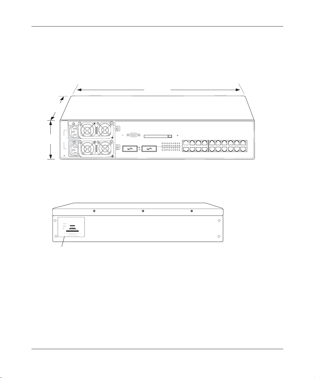
A WSS-2370 is two rack units (RUs) high and can be installed in a standard 48.26-cm (19-inch) equipment rack or on a
tabletop. Figure 2 shows a front view of a 2370 switch.
Figure 2. Nortel WSS-2370 Switch—Front View
44.2 cm
(17.4 inches)
46.23 cm
(18.2 inches)
8.81 cm
(3.47 inches)
100-240V
50/60 Hz
8A MAX
DISCONNECT
ALL POWER
BEFORE
SERVICING
Rst
Console
21 22
Mgmt
1
Link
AP
Link
AP
234 56789 10
11 12 13 14 15 16 17 18 19 20
840-9502-0068
Figure 3 shows a rear view of a WSS-2370. A switch’s serial number, MAC address, and other identifying information
are readily available on the serial number ID label.
Figure 3. Nortel WSS-2370 —Rear View
WSS-2270
840-9502-0063
Serial number ID label
The serial number ID label is in the same location on the rear of a 2360 or 2380 switch.
320656-A
Page 21
WLAN—Security Switch Overview 21
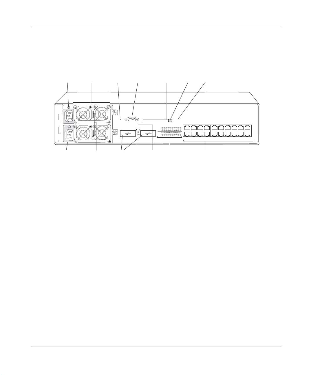
Figure 4 shows the external hardware features of a WSS-2370.
Figure 4. WSS-2370—Front Panel Control Features
Powe r
supply LED
100-240V
50/60 Hz
8A MAX
DISCONNECT
ALL POWER
BEFORE
SERVICING
AC power
inlet
Powe r
supply
Power supply
serial number
Restart
switch
Rst
21 22
GBIC slots
Serial
console port
Console
Gigabit
link
LEDs
Link
AP
Link
AP
Flash
card slot
Mgmt
11 12 13 14 15 16 17 18 19 20
10/100 and
AP/PoE
LEDs
Eject
button
1
Mgmt
LED
234 56789 10
10/100 Ethernet ports
840-9502-0053
WLAN—Security Switch 2300 Series Installation and Basic Configuration Guide
Page 22
22 WLAN—Security Switch Overview
(
)
2360 Switch
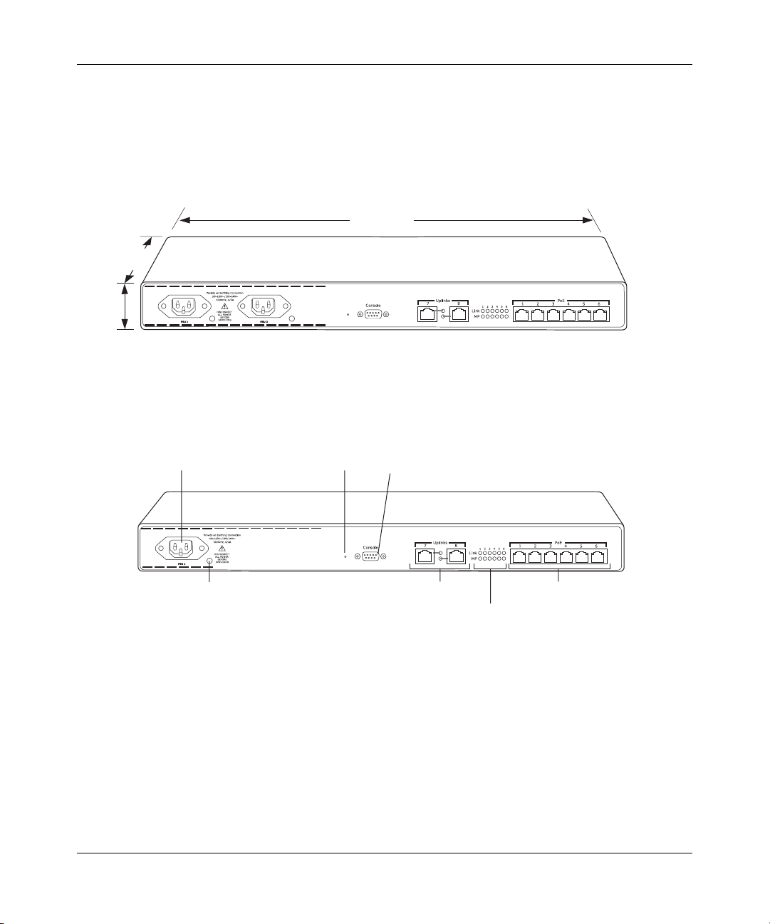
A 2360 switch is one RU high and also can be installed in a standard 48.26-cm (19-inch) equipment rack or on a
tabletop. Figure 5 shows a front view of a WSS-2360.
Figure 5. Nortel WSS-2360—Front View
44.2 cm
(17.4 inches)
25.6 cm
(10.8 inches)
Rst
4.4 cm
1.72 inches
Figure 6 shows the external hardware features of a WSS-2360.
Figure 6. WSS-2360—Front Panel Control Features
Powe r
supply
Powe r
supply LED
Restart
switch
The rear of the switch contains a label with the serial ID, MAC address, and other identifying information.
Rst
Serial
console port
10/100 Ethernet
uplink ports
10/100 and
AP/PoE LEDs
10/100 and AP
Ethernet ports
840-9502-0033
840-9502-0024
320656-A
Page 23
WLAN—Security Switch Overview 23
2380 Switch
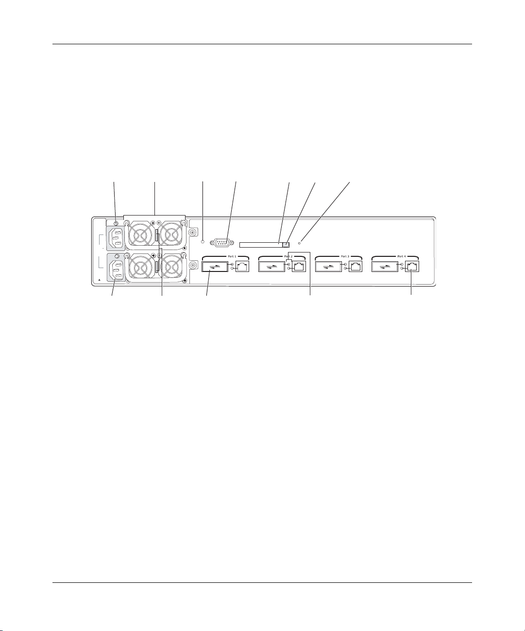
A 2380 switch is two rack units (RUs) high and can be installed in a standard 48.26-cm (19-inch) equipment
rack or on a tabletop. The dimensions of an 2380 switch are the same as the dimensions of a 2370 switch. (See
Figure 2.) Figure 7 shows a front view of a 2380 switch and identifies the external hardware features.
Figure 7. 2380 Switch—Front Panel Control Features
Powe r
supply LED
100-240V
50/60 Hz
8A MAX
DISCONNECT
ALL POWER
BEFORE
SERVICING
inlet
Powe r
supply
Power supply
serial number
Restart
switch
Rst
GBIC slotAC power
Serial
console port
Console
Flash
card slot
Mgmt
Eject
button
Gigabit
link
Mgmt
LED
1000BASE-TX port
LEDs
Like the other switch models, the rear of the 2380 switch contains a label with the serial ID, MAC address, and
other identifying information.
840-9502-0079
WLAN—Security Switch 2300 Series Installation and Basic Configuration Guide
Page 24
24 WLAN—Security Switch Overview
Management Features
• Serial console port—The serial console port provides a direct management connection to a WSS’s command-line
interface (CLI). The port has a DB-9 female connector and supports the EIA-232D signaling standard.
• Restart switch—The restart switch allows you to restart an 2360, 2380, or 2370 without removing the power
cord(s).
Caution! The 2350 does not have a restart switch but does have a factory
reset switch. Do not attempt to restart a configured 2350 by pressing its
factory reset switch! On an 2350 that is fully booted, the factory reset switch
erases the configuration. If you do accidentally press the factory reset switch and
erase the configuration, you can use the Web Quick Start to reconfigure the
switch.
• Status LEDs—The Ethernet ports and power supplies on all switch models have LEDs that indicate their status. The
management CPU on an 2370 or 2380 switch also has an LED. (For details, see “Status LEDs” on page 27.)
• Flash card slot (2370 and 2380 only)—The flash card slot is not used for normal WSS operation.
320656-A
Page 25

WLAN—Security Switch Overview 25
Power Features
• Power supplies—A 2370 or 2380 switch comes with one 100-240 VAC autosensing AC power supply.
You can add a second supply for load sharing and redundancy. The power supplies are hot-swappable.
A 2360 switch contains either one or two 100-120 VAC / 200-240 VAC autosensing AC power
supplies. The 2360 power supplies are fixed-configuration supplies and cannot be inserted or
removed.
A 2350 switch uses an external power supply, which comes with the switch.
WLAN—Security Switch 2300 Series Installation and Basic Configuration Guide
Page 26

26 WLAN—Security Switch Overview
Network Interfaces
• 10/100 Ethernet ports—A 2350 switch has two 10/100BASE-TX Ethernet ports. A WSS-2370 has twenty
10/100BASE-TX Ethernet ports. A 2360 switch has eight 10/100BASE-TX Ethernet ports. Each port has
a standard RJ-45 connector and uses Category 5 (Cat 5) cable based on the EIA/TIA-586 standard.
On the 2350, port 2 can be configured for AP access points and can support Power over
Ethernet (PoE). Port 1 is an uplink port only and does not support PoE.
On a 2370, ports 1 through 20 can be configured for AP access points and can support PoE. On
the 2360 switch, ports 1 through 6 can be configured for AP access points and can support PoE.
Ports 7 and 8 on the 2360 switch are uplink ports only and do not support PoE.
The 10/100 Ethernet ports on the 2360 switch provide automatic MDI/MDX, which
automatically crosses over the send and receive signals if required.
A 2380 switch provides high-bandwidth centralized control of many indirectly connected AP
access points. The switch does not have 10/100 Ethernet ports and does not provide PoE.
• Gigabit interface converter (GBIC) slots (2370 and 2380 only)—A 2370 switch has two slots allowing
insertion of 1000BASE-SX or 1000BASE-LX fiber-optic GBICs to provide gigabit Ethernet interfaces to
the network.
The fiber-optic GBICs have standard SC Duplex connectors and use either single-mode fiber
(SMF) for LX or multimode fiber (MMF) for SX. GBICs are available separately and are not
included with the switch.
A 2380 switch has four ports. Each port has a slot for a 1000BASE-SX or 1000BASE-LX
fiber-optic GBIC, and a built-in 1000BASE-TX copper interface with an RJ-45 connector. Only
one interface, copper or fiber, can be active on a port. The GBIC interface is active by default.
320656-A
Page 27

Status LEDs
The WSSs have LEDs that indicate port, power, and CPU status.
2360, 2380, and 2370 LEDs
Table 2 lists the LEDs for models 2370, 2360, and 2380.
.
Table 2: WSS Status LEDs—2370, 2360, 2380
LED Appearance Meaning
WLAN—Security Switch Overview 27
Mgmt
(2370 and 2380 only)
Power supply status Solid green DC power output is on.
Gigabit fiber link
activity
(2370 and 2380 only)
Gigabit copper link
activity
(2370 and 2380 only)
Link
(2370 and 2360 only)
Bright green, then fade
(repeated)
Note: This LED appearance
is sometimes called
breathing.
Blinking green WSS is booting.
Quickly blinking amber WSS was unable to boot completely.
Solid amber Power fault has occurred.
Unlit AC power is off.
Solid green 1000-Mbps fiber link is operational.
Blinking amber (2370) Traffic is active on the 1000-Mbps fiber link.
Blinking green (2380) Traffic is active on the 1000-Mbps fiber link.
Solid green 1000-Mbps copper link is operational.
Blinking green Traffic is active on the 1000-Mbps copper
Solid green 100-Mbps link is operational.
Solid amber 10-Mbps link is operational.
Blinking green Traffic is active on the 100-Mbps link.
Blinking amber Traffic is active on the 10-Mbps link.
WSS is operating normally.
link.
WLAN—Security Switch 2300 Series Installation and Basic Configuration Guide
Page 28

28 WLAN—Security Switch Overview
Table 2: WSS Status LEDs—2370, 2360, 2380 (continued)
LED Appearance Meaning
AP
(2370 and 2360 only)
Solid green For an AP access point’s active link, with
Alternating green and
amber
Solid amber PoE is on but no AP access point is
Blinking amber AP is not connected or is unresponsive, or
Unlit Port is not configured as an AP access port,
PoE enabled, all the following are true:
• AP access point has booted.
• AP access point has received a valid
configuration from the WSS.
• Management link with an AP access
point is operational.
AP access point is booting with an image
received from the WSS.
If the LED remains in this state indefinitely,
the boot or configuration attempt has failed.
connected to the link.
there is a PoE problem.
or PoE is off.
2350 LEDs
Figure 8 on page 28 shows the locations of the 2350 LEDs. Table 3 describes the LEDs.
Figure 8. 2350 LEDs
Factory Reset
LED
AP LED
320656-A
1
Link LED
2
Powe r
supply LED
Table 3: WSS Status LEDs—2350
LED Appearance Meaning
Power status Solid green The switch is receiving power.
Unlit The switch is not receiving power.
Page 29

WLAN—Security Switch Overview 29
Table 3: WSS Status LEDs—2350 (continued)
LED Appearance Meaning
Link
(ports 1 and 2)
Factory Reset
(port 1 only)
AP (port 2 only) Solid green For an AP access point’s active link, with
Solid green 100-Mbps link is operational.
Solid amber 10-Mbps link is operational.
Blinking green Traffic is active on the 100-Mbps link.
Blinking amber Traffic is active on the 10-Mbps link.
Solid green The switch is booting and is loading its
Blinking green The switch is booting but the factory reset
Unlit The switch has finished booting.
Alternating green and
amber
Solid amber PoE is on but no AP access point is
Blinking amber AP is not connected or is unresponsive, or
Unlit Port is not configured as an AP access port,
configuration file. This LED state lasts for
three seconds.
switch is being pressed. The switch does not
load its configuration file but instead
contacts WLAN Management Software to
request a configuration.
This LED state lasts for three seconds.
PoE enabled, all the following are true:
• AP access point has booted.
• AP access point has received a valid
configuration from the WSS.
• Management link with an AP access
point is operational.
AP access point is booting with an image
received from the WSS.
If the LED remains in this state indefinitely,
the boot or configuration attempt has failed.
connected to the link.
there is a PoE problem.
or PoE is off.
WLAN—Security Switch 2300 Series Installation and Basic Configuration Guide
Page 30

30 WLAN—Security Switch Overview
Software Features
WLAN 2300 System Software (WSS Software) provides a combination of standard wired LAN features and
wireless LAN features that enable you to integrate the switch into your wired network and provide network
access for wired or wireless users.
320656-A
Page 31

WLAN—Security Switch Overview 31
Management Features
• Serial and network command-line interface (CLI) access—You can access the CLI through a direct serial
connection or through the network using Secure Shell (SSH) or Telnet.
• WLAN Management Software management application—WLAN Management Software is an extensive GUI
application for planning, configuring, deploying, and managing a Nortel network and its users. WLAN
Management Software uses Secure Sockets Layer protocol (SSL) to interact with WSS Software.
• Software and configuration management—You can store multiple software images and configuration files in the
WSS’s nonvolatile storage.
• Web View manager—Web View is a Web-based application for configuring and managing a single WSS through a
Web browser. Web View creates a secure connection by using Hypertext Transfer Protocol over Secure Sockets
Layer (HTTPS).
WLAN—Security Switch 2300 Series Installation and Basic Configuration Guide
Page 32

32 WLAN—Security Switch Overview
Layer 2 Switching Features
• Spanning Tree Protocol (STP)—WSS Software supports Per-VLAN Spanning Tree (PVST+). PVST+ allows a
separate spanning tree in each virtual LAN (VLAN). Optional fast convergence features allow you to quickly
resume traffic forwarding after a topology change.
• Load-sharing port groups—You can configure multiple physical ports into a single logical link for traffic load
sharing and physical link redundancy.
• Virtual LANs (VLANs)—WSS Software supports logical segmentation of a switch’s ports into separate Layer 2
collision domains. A port can be a member of one or more VLANs. Each VLAN can have its own IP interface.
WSS Software supports the 802.1Q tag format.
• Internet Group Management Protocol (IGMP) snooping for multicast containment—The WSS can learn about the
multicast sources and receivers in the network and restrict forwarding for a multicast group to the users for that
group. IGMPv1 and IGMPv2 are supported.
320656-A
Page 33

WLAN—Security Switch Overview 33
IP Services
• IP interfaces—You can configure an IP interface for each VLAN.
• IP ping and traceroute—You can test IP connectivity between the WSS and other devices.
• Domain Name Service (DNS)—You can configure the switch to use DNS servers for name resolution. You also can
configure a default domain name to append to hostnames.
• Network Time Protocol (NTP)—A WSS can sets its time and date by polling an NTP server.
• System log—A WSS generates log messages to log system events. The log messages are stored locally and also can
be exported to syslog servers.
• Simple Network Management Protocol (SNMP)—A WSS can be configured to generate SNMP traps for major
system events.
WLAN—Security Switch 2300 Series Installation and Basic Configuration Guide
Page 34

34 WLAN—Security Switch Overview
Authentication, Authorization, and Accounting
• 802.1X—A WSS can authenticate users based on 802.1X protocols. Based on authentication, users are assigned
VLAN membership, access control, and roaming boundaries.
• MAC authentication—If a device does not support 802.1X, you can configure authentication based on the source
MAC address to assign VLAN membership, access control, and roaming boundaries.
• Guest authentication—Guests can be authenticated by a shared set of authorization attributes that assign VLAN
membership, access control, and roaming boundaries.
• Local and remote authentication—You can authenticate users locally using information configured on the WSS, or
use a Remote Authentication Dial-In User Service (RADIUS) server. When you use a remote server, the WSS can
enhance performance by performing some of the AAA tasks locally or distributing the load across multiple servers.
320656-A
Page 35

WLAN—Security Switch Overview 35
Roaming
• AP access point roaming—You can configure the WSS to allow users to roam from one AP access point to another
on the same WSS.
• Mobility Domain™ roaming—You also can configure a group of WSSs to allow users to roam from one switch to
another. Regardless of the wired subnet connections, each user maintains the same IP address and session across the
network.
• Session management—You can display session information and statistics for users.
WLAN—Security Switch 2300 Series Installation and Basic Configuration Guide
Page 36

36 WLAN—Security Switch Overview
RF Management
• Auto-RF—WSS Software can automatically assign channels and power settings to AP access points based on RF
information collected from the network.
• Radio frequency (RF) topology—With WLAN Management Software , you can verify site coverage and capacity.
• Rogue detection and countermeasures—AP access points can be used to gather RF information for validating an RF
deployment plan, and for detecting and combatting rogue access points.
• User-based RF—You can gather statistics on a per-user basis as users roam across the network.
320656-A
Page 37
Installing and Connecting a
WLAN—Security Switch
Unpacking a WSS . . . . . . . . . . . . . . . . . . . . . . . . . . . . . . . . . . . . . . . . . . . . . . . . . . . . 37
Installation Requirements and Recommendations . . . . . . . . . . . . . . . . . . . . . . . . . . . . 38
Installing a WSS . . . . . . . . . . . . . . . . . . . . . . . . . . . . . . . . . . . . . . . . . . . . . . . . . . . . . 42
Installing a Power Supply in a 2370 or 2380 Switch . . . . . . . . . . . . . . . . . . . . . . . . . . 46
Powering On a WSS . . . . . . . . . . . . . . . . . . . . . . . . . . . . . . . . . . . . . . . . . . . . . . . . . . 48
Connecting to a Serial Management Console . . . . . . . . . . . . . . . . . . . . . . . . . . . . . . . 49
Troubleshooting a Serial Management Connection . . . . . . . . . . . . . . . . . . . . . . . . . . . 51
Connecting to the Network . . . . . . . . . . . . . . . . . . . . . . . . . . . . . . . . . . . . . . . . . . . . . 51
Note. Before installing a WSS, you might need to generate a network plan with WLAN
Management Software . (See “WLAN Management Software Network Plan” on page 39.)
37
Unpacking a WSS
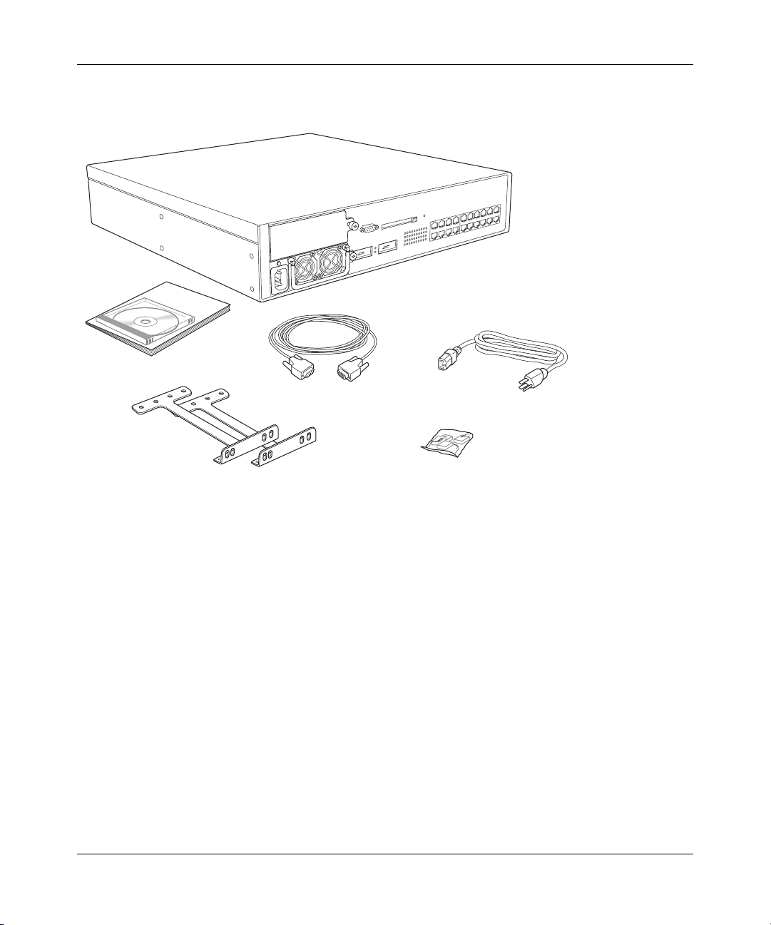
The shipping carton for a WSS contains the following items:
• One WSS, with one power supply (or two power supplies, if you ordered the 2361)
• For some countries, one country-specific power cord
• One serial cable for connection to the management console (not included with the 2350)
• Two rack-mount brackets (not applicable to the 2350)
• Four adhesive rubber feet
• One documentation pack that includes this guide
• One set of release notes
Figure 9 shows the contents of the shipping carton for a 2370 switch. The contents of a 2360 or 2380 shipping carton are
similar. The 2350 carton contains the switch, a power supply and cord, rubber feet, a documentation pack, and release
notes.
WLAN—Security Switch 2300 Series Installation and Basic Configuration Guide
Page 38
38 Installing and Connecting a WLAN—Security Switch
Figure 9. WSS-2370 Switch Shipping Carton Contents
WSS with
installed power supply
Documentation pack
Serial cable
Rack-mount brackets
Before you begin installation:
1 Open the carton and carefully remove the contents, if you have not already done so.
2 Place the packing materials back in the carton and save the carton.
3 Verify that you received each item in the previous list. If any item is missing or damaged,
contact Nortel.
Power cord
Rubber feet
840-9502-0054
Installation Requirements and Recommendations
For best results, follow these requirements and recommendations before installing a WSS.
320656-A
Page 39
Installing and Connecting a WLAN—Security Switch 39
WLAN Management Software Network Plan
If you are using WLAN Management Software to plan your Nortel Mobility System installation, Nortel recommends
that you create and verify a network plan for the entire Nortel network installation before installing WSSs or AP access
points. A network plan provides the following information:
• Number of WSSs required at your site, and where to install them
• Number of AP access points required for adequate WLAN capacity in each coverage area, and where to install them
• Configuration settings for all the WSSs and AP access points in the WLAN, which can be automatically deployed
to the devices by WLAN Management Software .
(For information about installing WLAN Management Software and creating and verifying a network plan, see the
Nortel WLAN Management Software User’s Guide.)
Installation Location
Caution! The WSS has been designed and tested to be installed in an operating
ambient temperature of 0° C to +50° C (32° F to 122° F). To reduce the risk of equipment
damage, install equipment with consideration to these ambient conditions.
Caution! Do not stack 2350 switches. Stacked 2350 switches can overheat and cause
loss of equipment functionality or permanent damage.
Caution! Ensure adequate airflow around 2350 switches. The 2350 switch uses
natural convection cooling and requires free entry of air. Airflow blockage can cause the
system to overheat and result in a loss of equipment functionality or permanent damage.
WSS-2370 and 2380 switch fans and air inlets are located on the sides of the switch. 2360 switch fans are located in the
rear of the switch and air inlets are located on the sides of the switch. In the 2370 and 2380 switches, separate power
supply fans are located on the front. Make sure these areas have adequate ventilation after installation. Do not block air
vents.
WLAN—Security Switch 2300 Series Installation and Basic Configuration Guide
Page 40

40 Installing and Connecting a WLAN—Security Switch
Cable Requirements
Warning! The gigabit Ethernet fiber-optic interfaces use Class 1 lasers. To
reduce the risk of eye injury, do not stare into the interface or otherwise direct
the laser beam into your eye. (For translations of this warning, see “Laser
Warning” on page 164.)
To avoid installation problems, use the proper cables.
Serial Console Cable
The serial console port has a female DB-9 connector and supports the EIA-232D signaling standard. You need
a standard DB-9-male-to-DB-9-female PC modem cable. Table 4 lists the pin signals.
Table 4: Serial Console Pin Signals
WSS Pin Usage PC Pin Usage
2 Receive 3 Transmit
3Transmit2Receive
5 Ground 5 Ground
Network Cables
Table 5 lists the interface types supported by WSSs and the cable type required for each type of interface.
Table 5: Ethernet Interfaces
Link Type Cable Type
10/100BASE-T Cat 5 copper
Straight-through or crossover signaling
1000BASE-SX Multimode 50-µm fiber SC 550 m (1804.5 feet)
Multimode 62.5-µm fiber SC 275 m (902.2 feet)
320656-A
Connector
Type
RJ-45 100 m (328 feet)
Maximum Distance
Page 41

Installing and Connecting a WLAN—Security Switch 41
Table 5: Ethernet Interfaces (continued)
Link Type Cable Type
1000BASE-LX Single mode 9/10-µm fiber SC 10,000 m (32,808.4 feet)
Multimode 50-µm fiber SC 550 m (1804.5 feet)
Multimode 62.5-µm fiber SC 550 m (1804.5 feet)
1000BASE-TX Cat 5 copper
Can use straight-through or crossover
signaling, provided all four wire pairs
are connected
Connector
Type
RJ-45 100 m (328 feet)
Maximum Distance
10/100 Ethernet Cable Wiring
Connections on the 10/100 ports require Category 5 (Cat 5) cable based on the EIA/TIA-586 standard. For direct
connection to an AP access point, a router, or an end station such as a PC, printer, or server, use a straight-through cable.
For direct connection to another switch, use a crossover cable. (The 10/100 Ethernet ports on the 2360 switch provide
automatic MDI/MDX, which automatically crosses over the send and receive signals if required.)
Table 6 lists the pin signals for 10/100 Ethernet straight-through wiring. Pins 4, 5, 7, and 8 are used only when Power
over Ethernet (PoE) is enabled on the port. RD means Receive Data and TD means Transmit Data.
Table 6: 10/100 Ethernet Straight-Through Pin Signals
WSS Other Device
Pin Function Pin Function
1RD+1TD+
2RD-2TD-
3TD+3RD+
4PoE+4PoE+
5PoE+5PoE+
6TD-6RD-
7PoE-7PoE-
8PoE-8PoE-
AP Cable Requirement
Use a straight-through Ethernet cable to connect an AP access point directly to a WSS or indirectly through another
device.
WLAN—Security Switch 2300 Series Installation and Basic Configuration Guide
Page 42

42 Installing and Connecting a WLAN—Security Switch
1000BASETX Gigabit Ethernet Cable Wiring
Use Cat 5 Enhanced (Cat 5E) or better cable. 1000BASE-TX uses all 8 wires in the cable. The wiring can be
straight-through or crossover. The port automatically configures its pin signals accordingly.
Note. PoE is not supported on 1000BASE-TX links. All wires in the cable are used for
data.
Installation Hardware and Tools
Caution! To reduce the risk of equipment damage, make sure the WSS is installed so
that the mechanical load on the device is evenly distributed. For example, make sure the
switch is level in the equipment rack, is evenly fastened by screws on either side, and does
not have a heavy object resting on one side of the switch.
Table 7 lists the mounting hardware and tools required for each type of installation.
Table 7: Required Mounting Hardware and Tools
Mounting Option
Equipment rack
• Front-mount or
center-mount option for
the 2370 or 2380 switch
• Front-mount option for the
2360 switch
Tab le to p
(applicable to all switch
models)
Required Hardware and
Tools
Mounting brackets Yes
Four rack-mount screws and
screwdriver
Note: Equipment racks vary, and the
screw and screwdriver type depend on
the equipment rack.
Power cords Yes (one)
Serial console cable Yes
Four adhesive rubber feet Yes
Power cord(s) Yes
Serial console cable Yes
Included with the
Product
No
Installing a WSS
You can mount a WSS-2370, 2360, or 2380 switch in a standard 48.26-cm (19-inch) equipment rack or on a tabletop.
Each WSS is shipped with two brackets for rack mounting and four adhesive rubber feet for tabletop mounting. The
320656-A
Page 43
Installing and Connecting a WLAN—Security Switch 43
WSS-2370 and 2380 mounting brackets support either front or center mounting. The 2360 mounting brackets support
front mounting only.
The 2350 switch does not have rack mounting brackets but can be installed on a tabletop.
To install a WSS, use one of the following procedures.
Warning! Earth grounding is required for a WSS installed in a rack. If you are
relying on the rack to provide ground, the rack itself must be grounded with a
ground strap to the earth ground. Metal screws attaching the switch to the rack
provide ground attachment to the rack. (For translations of this warning, see
“Earth Ground Warning” on page 165.)
Warning! In the U.S., overcurrent protection must be provided by the
installation. Branch circuit protection in accordance with National Fire Protection
Association (NFPA) 70, National Electrical Code (NEC) is required. Consideration
must be given to the electrical ratings on the WSS and branch circuit
protection. Do not install equipment such that the branch circuit current and
voltage protection is exceeded. Pay particular attention to the earthing
connection for the supply connections. When using an extension cord or power
strip, pay attention to the grounding type.
Caution! Do not stack 2350 switches. Stacked 2350 switches can overheat and cause
loss of equipment functionality or permanent damage.
Caution! Ensure adequate airflow around 2350 switches. The 2350 switch uses
natural convection cooling and requires free entry of air. Airflow blockage can cause the
system to overheat and result in a loss of equipment functionality or permanent damage.
Equipment Rack Installation
You can install a 2370 or 2380 switch into a front-mount or center-mount equipment rack. You can install a 2360 switch
into a front-mount equipment rack.
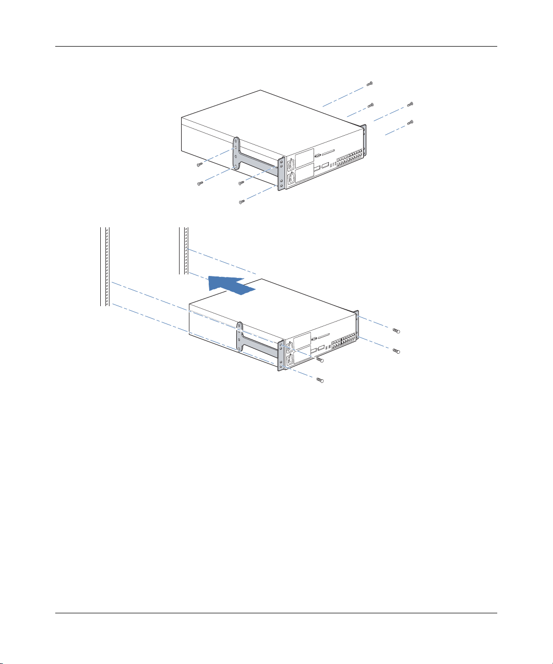
• Figure 10 shows how to install a 2370 or 2380 switch into a front-mount equipment rack. (Installation of a 2360
switch is similar.)
• Figure 11 shows how to install a 2370 or 2380 switch into a center-mount equipment rack.
Refer to these figures as you perform the procedure.
WLAN—Security Switch 2300 Series Installation and Basic Configuration Guide
Page 44
44 Installing and Connecting a WLAN—Security Switch
Figure 10. WSS-2370 or 2380 Installation—Front-Mount Equipment Rack
First, attach brackets to chassis.
320656-A
Then, install chassis into rack.
840-9502-0055
Page 45

Installing and Connecting a WLAN—Security Switch 45
Figure 11. 2370 or 2380 Installation—Center-Mount Equipment Rack
First, attach brackets to chassis.
Then, install chassis into rack.
840-9502-0057
1 Remove the four bracket screws from each side of the WSS.
2 Align a bracket over the screw holes:
● For a front-mount equipment rack, align the bracket so that the bracket flange is flush with the
WSS’s front panel and extends away from the switch.
● For a center-mount equipment rack, align the bracket so that the bracket flange is located near the
center screw holes.
3 Reinsert the screws to secure the brackets to the WSS.
4 Repeat for the other bracket.
Warning! Nortel recommends that you ask someone to assist you
with the remaining steps. If you accidentally drop the WSS, you can be
injured and the switch can be damaged. (For translations of this
warning, see “Rack Installation Warnings” on page 166.)
WLAN—Security Switch 2300 Series Installation and Basic Configuration Guide
Page 46
46 Installing and Connecting a WLAN—Security Switch
5 Lift the WSS into position in the equipment rack.
Warning! To prevent the WSS from slipping, do not release the
switch until all the rack-mount screws are tight. (For translations of this
warning, see “Rack Installation Warnings” on page 166.)
6 Insert the bottom rack-mount screws into the bracket flanges to secure the WSS to the equipment rack,
then insert the top screws.
7 Do one of the following:
● If you are installing a second power supply into a 2370 or 2380 switch, go to “Installing a Power
Supply in a 2370 or 2380 Switch” on page 46.
● If you are ready to turn on power, go to “Powering On a WSS” on page 48.
Tabletop Installation
1 On a clean work surface with no debris, carefully turn the WSS upside down.
2 Wipe the four placement locations for the rubber feet to clear away any oil or dust. The location areas are
marked by X’s.
3 Attach the four rubber adhesive feet over the X’s.
4 Turn the WSS right-side up, and place the switch in position on the table.
5 Do one of the following:
● If you are installing a second power supply into a WSS-2370 or 2380 switch, go to “Installing a
Power Supply in a 2370 or 2380 Switch”.
● If you are ready to turn on power, go to “Powering On a WSS” on page 48.
Installing a Power Supply in a 2370 or 2380 Switch
A 2370 or 2380 switch is shipped with a single 100-240 VAC autosensing AC power supply. One power supply
provides enough power for a fully configured system. You can add a second power supply for load sharing and redundancy. A WSS containing one power supply can have the supply installed in either slot. If the switch contains two power
supplies and one supply fails, the other supply automatically takes over to provide uninterrupted operation.
The power supplies are hot-swappable. You can remove or insert a power supply while the other power supply is
running.
Use the following procedures to install a second power supply or replace a failed power supply.
(You cannot insert or remove power supplies in a 2360 switch.)
Note. To attach the power supply to an 2350, see “Powering On a 2350” on page 49.
320656-A
Page 47
Installing and Connecting a WLAN—Security Switch 47
Installing a New Power Supply
1 If you are replacing a failed power supply and have not already removed it from the WSS, go to
“Replacing a Power Supply” on page 47.
2 If you are installing a new power supply in an unused slot, loosen the thumbscrew with a #2 Phillips-head
screwdriver and remove the cover plate.
Store the cover plate in a safe place in case you need to use it at another time.
3 Remove the new power supply from its packaging and lift the supply by grasping the front handle with
one hand and supporting the supply from the bottom with the other hand.
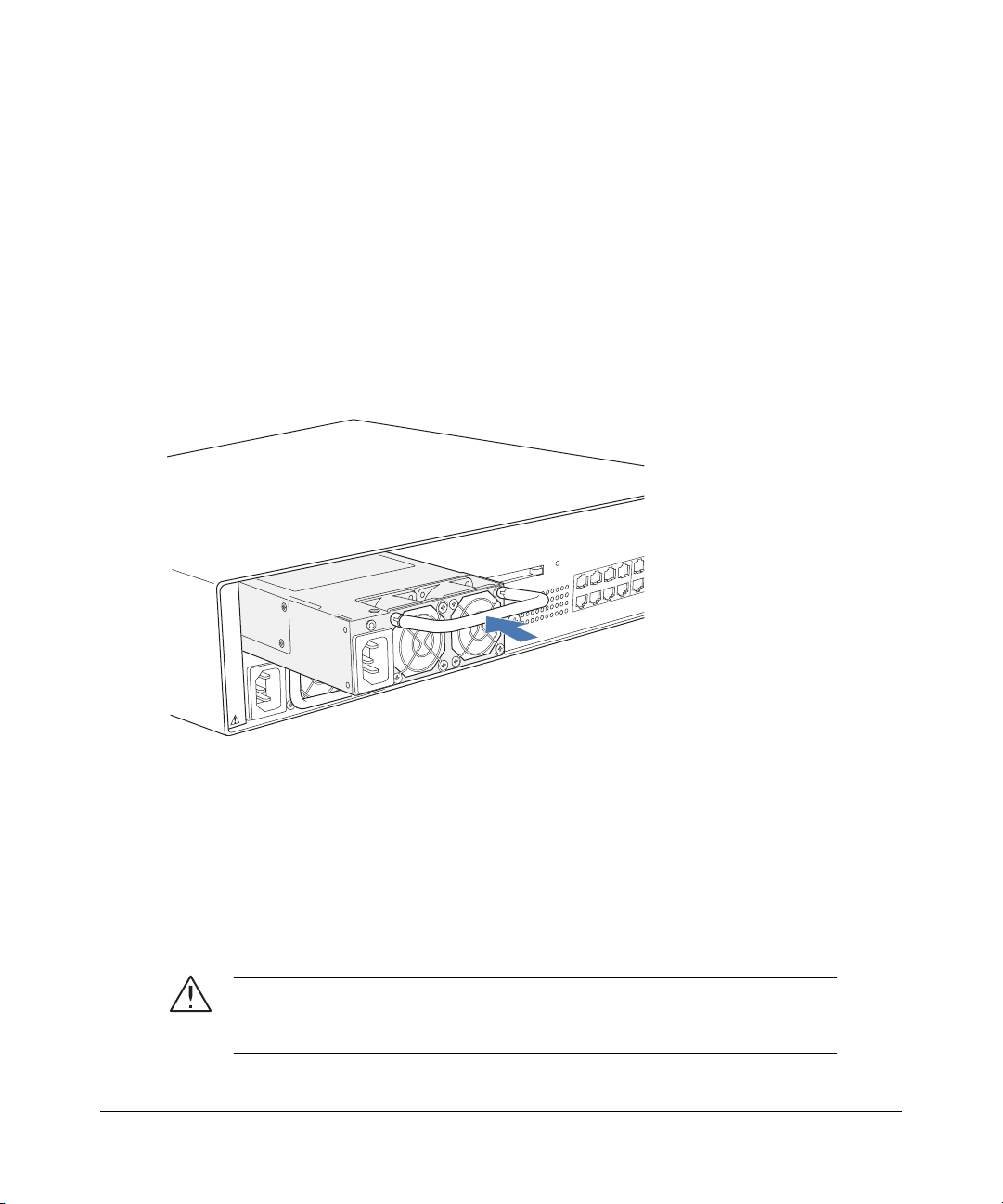
4 Insert the power supply into the WSS’s slot as shown in Figure 12, pushing gently but firmly until the
supply is fully seated and flush with the switch’s front panel.
Figure 12. Inserting a Power Supply in a 2370 or 2380 Switch
5 Tighten the thumbscrew using a #2 Phillips-head screwdriver.
6 Go to “Powering On a WSS” on page 48.
Replacing a Power Supply
1 Remove the power cord from the power supply.
2 Loosen the thumbscrew using a #2 Phillips-head screwdriver as shown in Figure 13.
3 Use the handle to pull the power supply partway out of the slot as shown in Figure 13.
Caution! Support the bottom of the power supply while removing it from the
WSS. If the rear of the power supply is not supported, the supply will fall when you
remove it, possibly damaging the rear components of the supply.
WLAN—Security Switch 2300 Series Installation and Basic Configuration Guide
840-9502-0060
Page 48

48 Installing and Connecting a WLAN—Security Switch
Figure 13. Removing a Power Supply from an 2370 or 2380 Switch
Loosen
thumbscrew
840-9502-0059
4 Place your other hand under the supply to support it and remove the supply the rest of the way
out of the slot.
5 Go to step 3 of “Installing a New Power Supply” on page 47.
Powering On a WSS
Warning! The WSS relies on the building’s installation for overcurrent
protection. Ensure that a fuse or circuit breaker no larger than 120 VAC,
15 A U.S. (240 VAC, 10 A international) is used on the phase conductors. (For
translations of this warning, see “Overcurrent Warning” on page 168.)
Powering On a 2360, 2370, or 2380
To power on an 2360, 2370, or 2380 switch:
320656-A
Page 49
1 Make sure any insertable power supply is fully seated in the WSS.
2 For each power supply that you are using on the WSS, attach a power cord to an AC power
source.
Note. If the WSS has two power supplies, use a separate AC power source for
each supply to add redundancy. If one power source fails, the switch can continue
to operate using the other power source.
3 Plug each power cord into a WSS power supply.
The WSS begins booting as soon as you plug in the power cord(s).
4 Observe the power supply LED for each connected power supply to verify that the LED is
steadily glowing green. This indicates normal power supply operation.
5 On the 2370 or 2380 switch only, wait a few seconds, then observe the Mgmt LED to verify that
it is breathing (repeatedly flashing bright green, then fading) to indicate that the WSS has
successfully booted and is operating normally.
Powering On a 2350
To power on a 2350 switch:
1 Plug the power supply into an AC power source.
2 Plug the power supply into the Power port.
The LED turns green when the 2350 is receiving power.
Installing and Connecting a WLAN—Security Switch 49
Connecting to a Serial Management Console
Initial configuration of the WSS requires a connection to the switch’s CLI through the serial console port.
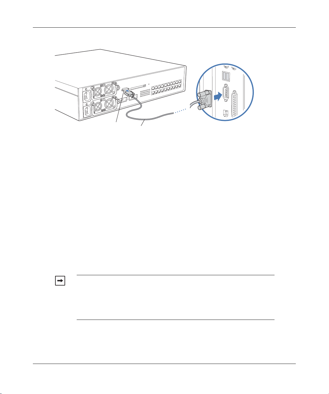
Figure 14 shows how to install a serial cable on a 2370 switch. The procedure is the same on an 2360, 2380, or
2350 switch. Refer to this figure as you perform the procedure. (For cable requirements, see “Serial Console
Cable” on page 40.)
WLAN—Security Switch 2300 Series Installation and Basic Configuration Guide
Page 50
50 Installing and Connecting a WLAN—Security Switch
Figure 14. Serial Cable Installation
Serial port Serial cable Serial port on computer
To connect a PC to the serial console port:
1 Insert the serial cable into the PC port as shown in Figure 14.
2 Insert the other end of the cable into the serial console port on the WSS as shown in Figure 14.
3 Start a standard VT100 terminal emulation application on the PC, and configure the following modem
settings:
● 9600 bps
● 8 bits
● 1 stop
● No parity
● Hardware flow control off or disabled
4 Open a connection on a serial port.
● If the WSS is already powered on, press Enter three times to display a command prompt:
2370>
Go to step 4 in “Accessing the CLI” on page 80.
Note. For simplicity, the command prompt examples in the documentation
show a switch model (such as 2370) and the CLI access level (> for restricted
access or # for enabled access) only. The default command prompt on your WSS
shows your switch’s model number and also contains the last three octets of the
switch’s MAC address. For example, the default command prompt on an 2370
switch with MAC address 00:0B:0E:00:04:0A is 2370-00040A>.
840-9502-0056
320656-A
● If a command prompt does not appear, go to “Troubleshooting a Serial Management Connection”.
Page 51

Installing and Connecting a WLAN—Security Switch 51
Troubleshooting a Serial Management Connection
1 Verify that the WSS is powered on.
2 Verify that the serial cable is fully inserted in the PC and WSS ports.
3 Verify that the correct modem settings are configured in the terminal emulation application:
● 9600 bps
● 8 bits
● 1 stop
● No parity
● Hardware flow control off or disabled
4 Verify that you opened the connection on the PC port connected to the WSS.
For example, if you inserted the cable in PC port COM1, make sure you open the connection on COM1
instead of COM2 or another port.
If none of the previous steps results in a management connection, use another serial cable.
Connecting to the Network
Use the following procedures to connect a WSS to AP access points or other 10/100 Ethernet devices and to gigabit
Ethernet devices.
Connecting to an AP Access Point or Other 10/100 Ethernet Device
Note. The 10/100 Ethernet ports are configured as wired network ports by default. You
must change the port type for locally connected AP access points, and for wired end
stations that use AAA through the WSS to access the network.
Note. For installations in Japan: Provide an earthing connection before you connect the
mains plug to the mains. When disconnecting the earthing connection, make sure to
disconnect only after you pull out the mains plug for the mains.
WLAN—Security Switch 2300 Series Installation and Basic Configuration Guide
Page 52

52 Installing and Connecting a WLAN—Security Switch
Figure 15 shows how to install a Cat 5 cable for a 10/100 Ethernet port. Refer to this figure as you perform the
procedure.
Figure 15. 10/100 Cat 5 Cable Installation
Ethernet port
To connect to an AP or other 10/100 Ethernet device:
1 Insert a Cat 5 cable with a standard RJ-45 connector as shown in Figure 15:
● For direct connection to an AP access point, use a straight-through cable.
● For connection to a router or to an end station such as a PC, printer, or server, use a
straight-through cable.
● For connection to another switch, use a crossover cable. (For cable requirements, see
“Network Cables” on page 40.)
Note. The 10/100 Ethernet ports on the 2360 switch provide automatic
MDI/MDX.
2 If the cable is directly attached to an AP access point:
● For a first-time installation, set the port type to activate the link. (For information, see
“Configuring APs for Wireless Users” on page 102.)
● If the port type is already set for an AP access point, observe the appearance of the AP
LED for the port:
Ethernet cable
(Cat 5 cable)
AP, switch, server
or other device
840-9502-0058
320656-A
Page 53

Installing and Connecting a WLAN—Security Switch 53
AP LED Appearance Meaning
Solid green For an AP access point’s active link, with PoE
Alternating green and amber AP access point is booting with an image received
Solid amber PoE is on, but no AP access point is connected to the
Blinking amber AP access point is unresponsive or there is a PoE
Unlit PoE is off.
3 If the cable is attached to a wired end station that uses AAA through the WSS to access the network:
● For a first-time installation, set the port type to activate the link. (For information, see “Configuring
a Port for a Wired Authentication User” on page 101.)
● If the port type is already set for a wired authentication port, go on to step 4.
4 If the cable is directly attached to a device other than an AP access point:
a Observe the appearance of the Link LED for the port:
enabled, all the following are true:
• AP access point has booted.
• AP access point has received a valid
configuration from the WSS.
• Management link with an AP access point is
operational.
For an AP access point’s secondary link, the link is
present.
from the WSS.
link.
problem.
Link LED Appearance Meaning
Solid green 100-Mbps link is operational.
Solid amber 10-Mbps link is operational.
Blinking green Traffic is active on the 100-Mbps link.
Blinking amber Traffic is active on the 10-Mbps link.
Unlit Link is not operational.
b If the Link LED is unlit, check the cable and verify that the device at the other end of the link is
operating.
WLAN—Security Switch 2300 Series Installation and Basic Configuration Guide
Page 54
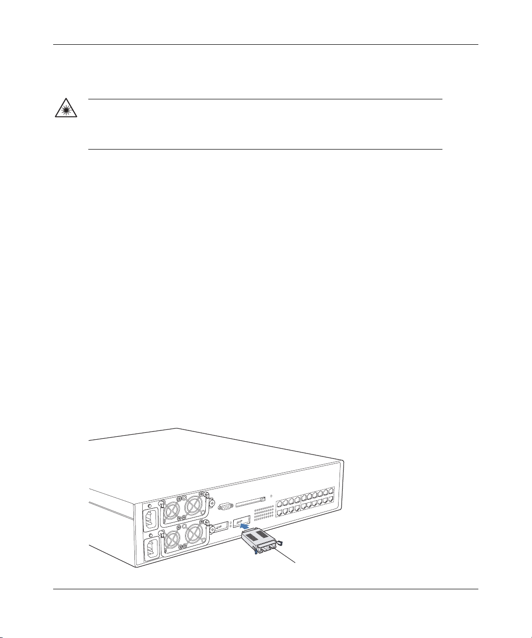
54 Installing and Connecting a WLAN—Security Switch
Connecting to Gigabit Ethernet Devices
Warning! The gigabit Ethernet fiber-optic interfaces use Class 1 lasers. To
reduce the risk of eye injury, do not stare into the interface or otherwise direct
the laser beam into your eye. (For translations of this warning, see “Laser
Warning” on page 164.)
Connecting to a Copper Gigabit Device (2380 only)
Insert a Cat 5 cable with a standard RJ-45 connector. The cable can use straight-through or crossover signalling.
1 Insert the Cat 5 cable into the port’s RJ-45 (copper) interface.
2 Access the command-line interface (CLI) on the switch, use the enable command to enter configuration
mode, and use the following command to set the active interface on the port to RJ-45 (copper):
set port preference port-list rj45
3 Observe the lower LED to the left of the port:
● If the LED is solid green, the 1000-Mbps link is operational.
● If the LED is blinking green, traffic is active on the 1000-Mbps link.
● If the LED is unlit, the link is not operational. Check the cable and verify that the device at the other
end of the link is operational.
Connecting to a Fiber Gigabit Device (2370 or 2380)
You must install a gigabit interface converter (GBIC) to connect a 2370 or 2380 switch to 1000BASE-SX or
1000BASE-LX cable. Figure 16 shows how to install a GBIC. Figure 17 shows how to remove one. Refer to these
figures as you perform the procedures. (For cable requirements, see “Network Cables” on page 40.)
Figure 16. GBIC Installation in 2370 Switch
GBIC
320656-A
840-9502-0064
Page 55
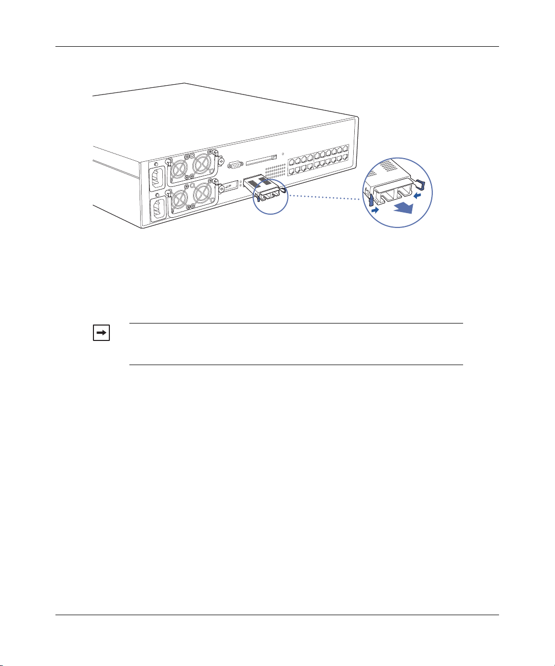
Installing and Connecting a WLAN—Security Switch 55
Figure 17. GBIC Removal from 2370 Switch
To install a GBIC:
1 Insert the GBIC into a GBIC slot on the front panel until it clicks into place.
2 Remove the protective covering(s) from the port connector(s) and set them aside in a safe place for later
use.
3 Insert the network cable.
Note. For 1000BASE-SX or 1000BASE-LX fiber, make sure you insert the two
cable ends in the proper sides (transmit or receive). Otherwise, the link does not
work.
Squeeze the
lock clips to
release GBIC.
840-9502-0041
4 Observe the upper LED to the right of the GBIC port:
● If the LED is green, the 1000-Mbps link is operational.
● If the LED is blinking amber, traffic is active on the 1000-Mbps link.
● If the LED is unlit, the link is not operational. Check the cable and verify that the device at the other
To remove a GBIC:
1 Remove the network cable(s).
2 Insert the protective covering(s) into the port connector(s).
3 Squeeze the clips on the sides of the GBIC and pull the GBIC out of the slot.
end of the link is operational.
WLAN—Security Switch 2300 Series Installation and Basic Configuration Guide
Page 56

56 Installing and Connecting a WLAN—Security Switch
320656-A
Page 57
WSS Setup Methods
Overview . . . . . . . . . . . . . . . . . . . . . . . . . . . . . . . . . . . . . . . . . . . . . . . . . . . . . . . . . . . 57
How a WLAN—Security Switch Gets its Configuration . . . . . . . . . . . . . . . . . . . . . . 59
Web Quick Start (2350 and 2360 Only) . . . . . . . . . . . . . . . . . . . . . . . . . . . . . . . . . . . 60
CLI quickstart Command . . . . . . . . . . . . . . . . . . . . . . . . . . . . . . . . . . . . . . . . . . . . . . . 63
Remote WSS Configuration . . . . . . . . . . . . . . . . . . . . . . . . . . . . . . . . . . . . . . . . . . . . 67
Opening the QuickStart Network Plan in WLAN Management Software . . . . . . . . . 77
This chapter describes the methods you can use to configure a WSS, and refers you to information for each method.
Depending on your configuration needs, you can use one or a combination of these methods.
Note. For easy installation, use one of the quick-start methods described in this chapter
instead of using the CLI instructions in later chapters in the manual.
57
Overview
WSS Software provides the following quick-start methods for new (unconfigured) switches:
• Web Quick Start (2350 and 2360 only)
•CLI quickstart command
You can use either quick-start method to configure a switch to provide wireless service. You also can use any of the
following management applications to configure a new switch or to continue configuration of a partially configured
switch:
• WLAN Management Software
•CLI
•Web View
Quick Starts
The Web Quick Start enables you to easily configure a 2350 or 2360 switch to provide wireless access to up to ten users.
The Web Quick Start is accessible only on unconfigured 2350 and 2360 switches. The interface is not available on other
switch models or on any switch that is already configured.
The quickstart command enables you to configure a 2350, 2360, 2370, or 2361 switch to provide wireless access to any
number of users.
WLAN—Security Switch 2300 Series Installation and Basic Configuration Guide
Page 58
58 WSS Setup Methods
WLAN Management Software
You can use WLAN Management Software to remotely configure a switch using one of the following
techniques:
• Drop ship—On model 2350 only, you can press the factory reset switch during power on until the right
LED above port 1 flashes for 3 seconds. Activating the factory reset causes the 2350 to bypass the Web
Quick Start and request its configuration from WLAN Management Software instead.
• Staged WSS—On any switch model, you can stage the switch to request its configuration from WLAN
Management Software , by preconfiguring IP parameters and enabling the auto-config option.
(These options are described in more detail in “Remote WSS Configuration” on page 67.)
You also can use WLAN Management Software to plan your network, create WSSs in the plan, then deploy
the switch configurations to the real switches. For information, see the following:
• Nortel WLAN Management Software User’s Guide
• Nortel WLAN Management Software Reference Manual
To open a sample network plan, see “Opening the QuickStart Network Plan in WLAN Management Software”
on page 77.
CLI
You can configure a switch using the CLI by attaching a PC to the switch’s Console port. See the following:
• “Configuring a 2370, 2360, or 2380 Switch for Basic Service” on page 79
• “Configuring a 2350 Switch for a Branch Office” on page 125
• Nortel WLAN 2300 System Software Configuration Guide
After you configure the switch for SSH or Telnet access, you also can use these protocols to access the CLI.
Web View
You can use a switch’s web management interface, Web View, to configure the switch. For access information, see “Enabling and Logging Into Web View” on page 97.
Note. Web View is different from the Web Quick Start application. Web View is a
web-based management application that is available at any time on a switch that already
has IP connectivity. (Web View access also requires the switch’s HTTPS server to be
enabled.) The Web Quick Start application is accessible only on unconfigured switches.
320656-A
Page 59
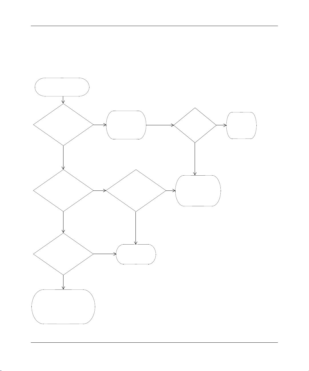
WSS Setup Methods 59
How a WLAN—Security Switch Gets its Configuration
Figure 18 shows how a WSS gets a configuration when you power it on.
Figure 18. WSS Startup Algorithm
Switch is powered on.
Does switch have
a configuration?
No
Model WSS-2350?
No
Model WSS-2360?
No
Ye s
Ye s
Ye s
Ye s
Switch boots
using its
configuration file.
Was factory reset
pressed during
power on?
Web Quick Start
is enabled.
No
Ye s
Is auto-config
enabled?
Ye s
Switch contacts
WMS
to request
configuration.
No
Switch
displays
CLI prompt.
Boots with no configuration.
You must use the CLI to
start configuring the switch.
WLAN—Security Switch 2300 Series Installation and Basic Configuration Guide
Page 60
60 WSS Setup Methods
Web Quick Start (2350 and 2360 Only)
You can use the Web Quick Start to configure the switch to provide wireless access to up to ten network users.
To access the Web Quick Start, attach a PC directly to port 1 or port 2 on the switch and use a web browser on
the PC to access IP address 192.168.100.1. (For more detailed instructions, see “Accessing the Web Quick
Start” on page 61.)
Note. The Web Quick Start application is different from Web View. Web View is a
web-based management application that is available at any time on a switch that already
has IP connectivity. (Web View access also requires the switch’s HTTPS server to be
enabled.) The Web Quick Start application is accessible only on unconfigured switches.
Note. The Web Quick Start application is supported only on switch models 2350 and
2360. After you finish the Web Quick Start, it will not be available again unless you clear
(erase) the switch’s configuration.
Web Quick Start Parameters
The Web Quick Start enables you to configure basic wireless access for a small office. You can use the Web
Quick Start to configure the following parameters:
• System name of the switch
• Country code (the country where wireless access will be provided)
• Administrator username and password
• Management IP address and default gateway
• Time and date (statically configured or provided by an NTP server)
• Management access
You can individually select Telnet, SSH, and Web View. You also can secure the Console port.
Access requires the administrator username and password.
• Power over Ethernet (PoE), for ports directly connected to AP access points
• SSIDs and authentication types. The Web Quick Start enables you to configure one secure SSID and one
clear SSID. You can configure additional SSIDs using the CLI or WLAN Management Software .
• Usernames and passwords for your wireless users. You can configure up to ten users with the Web Quick
Start. To configure additional users, use the CLI or WLAN Management Software .
Web Quick Start Requirements
To use the Web Quick Start, you need the following:
320656-A
Page 61
WSS Setup Methods 61
• AC power source for the switch
• PC with an Ethernet port that you can connect directly to the switch
• Category 5 (Cat 5) or higher Ethernet cable
If the PC is connected to the network, power down the PC or disable its network interface card (NIC), then unplug the
PC from the network.
Note. You can use a Layer 2 device between the switch and the PC. However, do not
attach the switch to your network yet. The switch requires the PC you attach to it for
configuration to be in the 192.168.100.x subnet, and uses the WSS Software DHCP server
to assign the PC an address from this subnet. If you attach the unconfigured switch to your
network, the switch disables the WSS Software DHCP server, if the switch detects another
DHCP server on the network. If the network does not have a DCHP server, the switch’s
DHCP server remains enabled and will offer IP addresses in the 192.168.100.x subnet in
response to DHCP Requests.
Accessing the Web Quick Start
To access the Web Quick Start:
1 Use a Category 5 (Cat 5) or higher Ethernet cable to connect the switch directly to a PC that has a web
browser.
2 Connect the switch to an AC power source.
If the green power LED is lit, the switch is receiving power.
Note. If you are configuring an 2350, do not press the factory reset switch
during power on. Pressing this switch on an unconfigured switch causes the switch
to attempt to contact a WLAN Management Software server instead of displaying
the Web Quick Start. (Other switch models also have reset switches, but the reset
switch simply restarts these other models without clearing the configuration.)
3 Enable the PC’s NIC that is connected to the switch, if not already enabled.
4 Use a web browser to access IP address 192.168.100.1.
This is a temporary, well-known address assigned to the unconfigured switch when you power it on. The
Web Quick Start enables you to change this address.
The first page of the Quick Start Wizard appears.
WLAN—Security Switch 2300 Series Installation and Basic Configuration Guide
Page 62
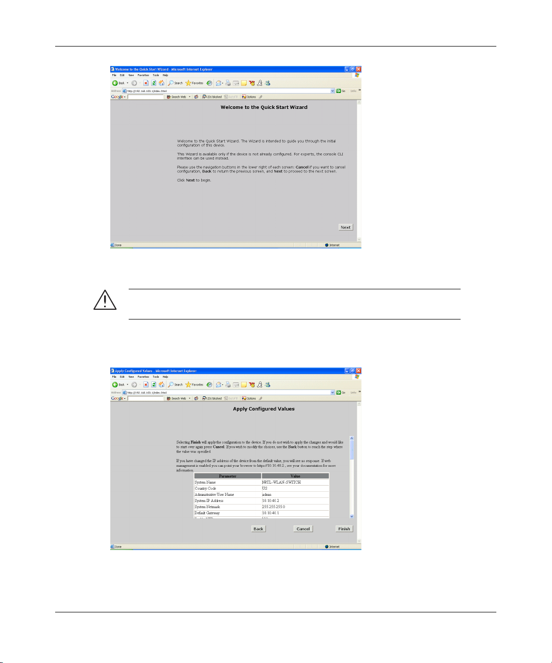
62 WSS Setup Methods
5 Click Next to begin. The wizard screens guide you through the configuration steps.
Caution! Use the wizard’s Next and Back buttons to navigate among the
wizard pages. Do not use the browser’s navigation buttons.
320656-A
6 After guiding you through the configuration, the wizard displays a summary of the configuration values
you selected. Here is an example:
7 Review the configuration settings, then click Finish to save the changes or click Back to change settings.
If you want to quit for now and start over later, click Cancel.
Page 63

WSS Setup Methods 63
If you click Finish, the wizard saves the configuration settings into the switch’s configuration file. If the
switch is rebooted, the configuration settings are restored when the reboot is finished.
The switch is ready for operation. You do not need to restart the switch.
Caution! On a 2350, do not press the factory reset switch! On an 2350 that is fully
booted, the factory reset switch erases the configuration. If you do accidentally press the
factory reset switch and erase the configuration, you can use the Web Quick Start to
reconfigure the switch.
For more advanced configuration, use the CLI or WLAN Management Software . See the following:
• “Configuring a 2370, 2360, or 2380 Switch for Basic Service” on page 79
• “Configuring a 2350 Switch for a Branch Office” on page 125
• Nortel WLAN 2300 System Software Configuration Guide
• Nortel WLAN 2300 System Software Command Reference
• Nortel WLAN Management Software User’s Guide
• Nortel WLAN Management Software Reference Manual
CLI quickstart Command
The quickstart command runs a script that interactively helps you configure the following items:
• System name
• Country code (regulatory domain)
• System IP address
• Default route
• Administrative users and passwords
• Unencrypted (clear) SSID names
• Usernames and passwords for guest access using WebAAA
• Encrypted (crypto) SSID names and dynamic WEP encryption for encrypted SSIDs’ wireless traffic
• Usernames and passwords for secure access using 802.1X authentication using PEAP-MSCHAP-V2 and secure
wireless data encryption using dynamic Wired Equivalent Privacy (WEP)
• Directly connected AP access points
• Distributed AP access points
The quickstart command displays a prompt for each of these items, and lists the default if applicable. You can advance
to the next item, and accept the default if applicable, by pressing Enter.
Depending on your input, the command also automatically generates the following key pairs and self-signed certificates:
• SSH key pair (always generated)
• Admin key pair and self-signed certificate (always generated)
WLAN—Security Switch 2300 Series Installation and Basic Configuration Guide
Page 64
64 WSS Setup Methods
• EAP (802.1X) key pair and self-signed certificate (generated if you type usernames and passwords for users of
encrypted SSIDs)
• Web-based AAA key pair and self-signed certificate (generated if you type usernames and passwords for users of
unencrypted SSIDs)
The command automatically places all ports that are not used for directly connected AP access points into the default
VLAN (VLAN 1).
Caution! The quickstart command is for configuration of a new switch only. After
prompting you for verification, the command erases the switch’s configuration before
continuing. If you run this command on a switch that already has a configuration, the
configuration will be erased. In addition, error messages such as Critical AP Notice for
directly connected APs can appear.
To run the quickstart command:
1 Attach a PC to the WSS’s serial console port. (Use these modem settings: 9600 bps, 8 bits, 1 stop, no
parity, hardware flow control disabled.)
2 Press Enter three times, to display a username prompt (Username:), a password prompt (Password:), and
then a command prompt such as the following:
2370-aabbcc>
(Each switch has a unique system name that contains the model number and the last half of the switch’s
MAC address.)
3 Access the enabled level (the configuration level) of the CLI:
2370-aabbcc> enable
4 Press Enter at the Enter password prompt.
5 Type quickstart. The command asks you a series of questions. You can type ? for more help. To quit,
press Ctrl+C.
One of the questions the script asks is the country code. For a list of valid country codes, see “Specifying
the Country of Operation” on page 98.
Another question the script asks is, “Do you wish to configure wireless?” If you answer y, the script goes
on to ask you for SSID and user information, for unencrypted and encrypted SSIDs. If you answer n, the
script generates key pairs for SSH and the administrative users you entered, generates a self-signed
administrative certificate, and then ends.
Quickstart Example
This example configures the following parameters:
• System name: 2370-Corp
• Country code (regulatory domain): US
320656-A
Page 65

WSS Setup Methods 65
• System IP address: 10.10.10.4, on IP interface 10.10.10.4 255.255.255.0
Note. The quickstart script asks for an IP address and subnet mask for the
system IP address, and converts the input into an IP interface with a subnet mask,
and a system IP address that uses that interface. Likewise, if you configure this
information manually instead of using the quickstart command, you must
configure the interface and system IP address separately.
• Default route: 10.10.10.1
• Administrative user mxadmin, with password letmein. The only management access the switch allows by default is
CLI access through the serial connection.
• System Time and date parameters:
● Date: 15th of November, 2004
● Time: 6:58 PM
● Timezone: PST (Pacific Standard Time), with an offset of -8 hours from Universal Coordinated Time
(UTC)
• Unencrypted SSID name: public
• Username user1 and password pass1 for WebAAA; username user2 and password pass2 for WebAAA
• Encrypted SSID name: corporate
• Username alice and password alicepass for 802.1X authentication; username bob and password bobpass for
802.1X authentication
• Directly connected AP access points on port 2 and 3, each model 2330 (applies only to WSS models 2360 and
2370)
The IP addresses, usernames, and passwords in this document are examples. Use values that are appropriate for your
organization.
If you configure time and date parameters, you will be required to enter a name for the timezone, and then enter the value
of the timezone (the offset from UTC) separately. You can use a string of up to 32 alphabetic characters as the timezone
name.
Figure 19 shows an example. Users bob and alan can access encrypted SSID corporate on either of the AP access points.
Users user1 and user2 can use the same APs to access unencrypted SSID public. Although the same hardware supports
both SSIDs and sets of users, AAA ensures that only the users who are authorized to access an SSID can access that
SSID. Users of separate SSIDs can even be in the same VLAN, as they are in this example.
WLAN—Security Switch 2300 Series Installation and Basic Configuration Guide
Page 66
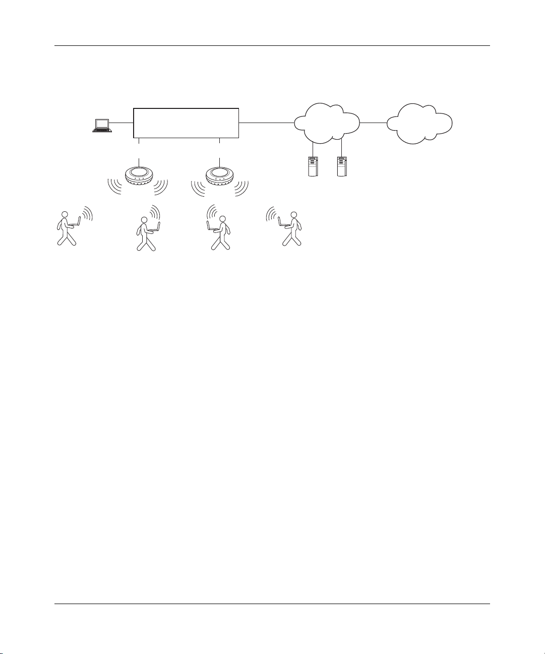
66 WSS Setup Methods
Figure 19. Single-Switch Deployment
alan
Console
WSS-2270-Corp
Por t
2
user1
10.10.10.4
Por t
3
user2
Backbone
Corporate resources
bob
Internet
2370-aabbcc# quickstart
This will erase any existing config. Continue? [n]: y
Answer the following questions. Enter '?' for help. ^C to break
out
System Name [2370]: 2370-Corp
Country Code [US]: US
System IP address []: 10.10.10.4
System IP address netmask []: 255.255.255.0
Default route []: 10.10.10.1
Admin username [admin]: mxadmin
Admin password []: letmein
Do you wish to set the time? [y]: y
Enter the date (dd/mm/yy) []: 15/11/04
Enter the time (hh:mm:ss) []: 18:58:00
Enter the timezone []: PST
Enter the offset from GMT for 'PST' in hh:mm [0:0]: -8
Do you wish to configure wireless? [y]: y
Enter a clear SSID to use: public
Do you want to do WEB-AAA? [y]: y
Enter a username with which to do web-aaa, <cr> to exit: user1
Enter a password for guesta: pass1
Enter a username with which to do web-aaa, <cr> to exit: user2
Enter a password for guestb: pass2
Enter a username with which to do web-aaa, <cr> to exit:
Do you want to do 802.1x and PEAP-MSCHAPv2? [y]: y
Enter a crypto SSID to use: corporate
Enter a username with which to do PEAP-MSCHAPv2, <cr> to exit:
alan
320656-A
Page 67

WSS Setup Methods 67
Enter a password for alice: alanpass
Enter a username with which to do PEAP-MSCHAPv2, <cr> to exit:
bob
Enter a password for bob: bobpass
Enter a username with which to do PEAP-MSCHAPv2, <cr> to exit:
Do you wish to configure access points? [y]: y
Enter a port number [1-20] on which an AP resides, <cr> to exit:
2
Enter AP model on port 2: AP-2330
Enter a port number [1-20] on which an AP resides, <cr> to exit:
3
Enter AP model on port 3: AP-2330
Enter a port number [1-20] on which an AP resides, <cr> to exit:
Do you wish to configure distributed access points? [y]: n
success: created keypair for ssh
success: created keypair for admin
success: created self-signed certificate for admin
success: created keypair for eap
success: created self-signed certificate for eap
success: created keypair for webaaa
success: created self-signed certificate for webaaa
success: remember to save this config
2370-aabbcc# save config
6 Optionally, enable Telnet.
2370-aabbcc# set ip telnet server enable
7 Verify the configuration changes.
2370-aabbcc# show config
8 Save the configuration changes.
2370-aabbcc# save config
Remote WSS Configuration
You can use WLAN Management Software Services running in your corporate network to configure WSSs in remote
offices. The following remote configuration scenarios are supported:
• Drop ship—WLAN Management Software Services running in the corporate network can configure a 2350 switch
shipped directly to a remote office. This option does not require any preconfiguration of the switch.
• Staged—You can stage any model of switch by preconfiguring IP connectivity and enabling auto-config, then
sending the switch to the remote office. The switch contacts WLAN Management Software Services in the
corporate network to complete its configuration.
The drop ship option is supported only for the 2350. The staged option is supported for all switch models. Both options
require WLAN Management Software Services. If you know a switch’s serial number, you can create a complete
configuration for the switch in WLAN Management Software . When the switch requests its configuration from WLAN
Management Software , WLAN Management Software sends the configuration for that serial number. If you do not
WLAN—Security Switch 2300 Series Installation and Basic Configuration Guide
Page 68
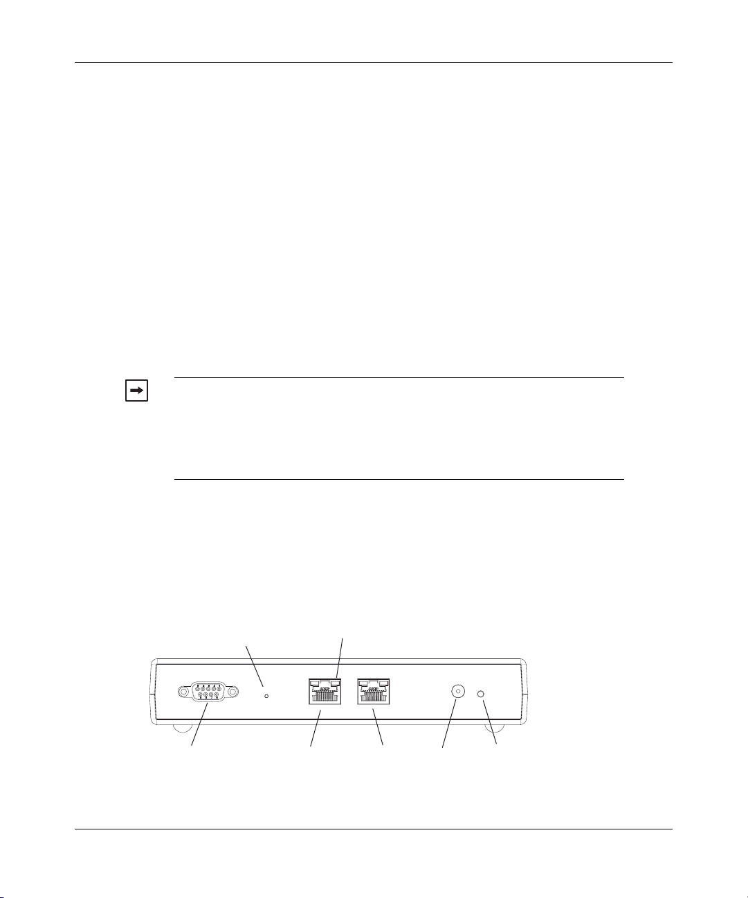
68 WSS Setup Methods
know the switch’s serial number, you can upload the partially configured switch into WLAN Management Software ,
finish its configuration, then deploy the completed configuration back to the switch.
How Remote WSS Configuration Works
Drop Ship (2350 Only)
1 The 2350 is shipped directly to the remote office where it will be deployed.
2 The network administrator at the corporate office preconfigures the switch in a WLAN Management
Software network plan. The switch configuration must have a name for the switch, the model must be
2350, and the serial number must match the switch’s serial number. The configuration should also include
all other settings required for the deployment, including AP configuration, SSIDs, AAA settings, and so
on.
3 Someone at the remote office where the switch is delivered physically installs the switch by connecting
port 1 to the network. If the switch will manage a directly connected AP, the AP needs to be physically
installed and connected by an Ethernet cable to port 2. If Distributed APs will be managed, these also
must be physically installed, connected to the network by Ethernet cables, and connected to Power over
Ethernet (PoE) sources.
Note. Drop ship configuration requires a DHCP server at the remote office. The
2350 uses the DHCP server to obtain an IP configuration in order to communicate
with WLAN Management Software Services in the corporate network. The drop
ship option also requires an entry in the local DNS server that maps the hostname
wlan-config-srv to the IP address of the host where WLAN Management Software
Services are installed.
4 The person at the remote office powers on the 2350, and inserts a paperclip or similar object into the
2350’s factory reset hole to press the factory reset switch. Normally, the factory reset LED (the right LED
above port 1) remains solidly lit for 3 seconds after power on. However, when the factory reset switch is
pressed, the LED flashes for 3 seconds instead.
Figure 20 shows the location of the factory reset switch and the LED.
Figure 20. Factory Reset Switch on 2350
Factory Reset
switch
Serial
console port
10/100 Ethernet
uplink port
Factory Reset
LED
1
10/100 and AP
Ethernet port
2
320656-A
Powe r
supply input
Powe r
supply LED
Page 69

WSS Setup Methods 69
5 Because the factory reset switch was pressed while the switch was starting, the 2350 configures the
following items, to enable itself to contact WLAN Management Software Services:
● Self-signed administrative certificate (required for communication with WLAN Management
Software )
● Ports 1 and 2 in the default VLAN (VLAN 1)
● DHCP client on VLAN 1 enabled
6 The 2350 uses the DHCP client to obtain an IP configuration from a local DHCP server. After obtaining
an IP configuration, the switch sends a DNS query for the IP address of well-known hostname
wlan-config-srv.
7 DNS replies with the IP address of the host where WLAN Management Software Services are installed.
The 2350 sends a configuration request to WLAN Management Software Services.
8 WLAN Management Software receives the configuration request, and looks in the currently open
network plan for an 2350 configuration with the same serial number as the one in the configuration
request.
● If the network plan contains a configuration with a matching serial number, WLAN Management
Software deploys the configuration to the switch and restarts the switch. The switch boots using the
configuration it received from WLAN Management Software . (See “Preconfiguring a Switch in
WLAN Management Software”.)
● If the network plan does not have a configuration with a matching serial number, a verification
warning appears in WLAN Management Software . The warning lists the switch’s serial number and
IP address. The network administrator can upload the switch into the network plan, configure switch
parameters, and deploy the configuration to the switch. (See “Uploading a Partially Configured
Switch and Completing its Configuration with WLAN Management Software” on page 76.)
Staged WSS
1 The switch is shipped to a network administrator who configures IP address and DNS information on the
switch, and enables the auto-config option, to configure the switch to contact WLAN Management
Software Services in the corporate network.
The network administrator can configure the switch to use a DCHP client to obtain IP information, or can
statically configure the information. The IP address and default gateway are required.
DNS information is optional, but is recommended if DNS is available. If DNS is available, an entry must
be added to the DNS server that maps the IP address of the host where WLAN Management Software
Service are installed to the well-known hostname wlan-config-srv. Otherwise, an IP alias can be
configured on the switch itself to map the address to the hostname.
2 The preconfigured switch is shipped to the remote office where it will be deployed.
3 Someone at the remote office physically installs the switch and APs.
4 The person at the remote office powers the switch on. The switch boots using the configuration created
during staging.
5 The switch either uses its DHCP client to obtain an IP address from a local DHCP server, or uses a
statically configured address. This depends on the switch’s preconfiguration.
6 If the auto-config option is enabled, the switch sends a DNS query for the IP address of well-known
hostname wlan-config-srv.
7 DNS replies with the IP address of the host where WLAN Management Software Services are installed.
The switch sends a request to WLAN Management Software Services in the corporate network for a
configuration. (If the auto-config option is not enabled, the switch boots using its configuration file. You
can use the CLI, WLAN Management Software , or Web View to complete its configuration.)
WLAN—Security Switch 2300 Series Installation and Basic Configuration Guide
Page 70

70 WSS Setup Methods
8 WLAN Management Software receives the configuration request, and looks in the currently open
network plan for a switch configuration with the same model and serial number as the one in the
configuration request.
● If the network plan contains a configuration with a matching model and serial number, WLAN
Management Software sends the configuration to the switch and restarts the switch. The switch
boots using the configuration it received from WLAN Management Software . (See “Preconfiguring
a Switch in WLAN Management Software”.)
● If the network plan does not have a configuration with a matching model and serial number, a
verification warning appears in WLAN Management Software . The warning lists the switch’s serial
number and IP address. The network administrator can upload the switch into the network plan,
configure switch parameters, and deploy the configuration to the switch. (See “Uploading a Partially
Configured Switch and Completing its Configuration with WLAN Management Software” on
page 76.)
Staging a WSS for Configuration by WLAN Management Software
The auto-config option must be enabled on a WSS in order for the switch to try to contact WLAN Management Software
Services for configuration. The auto-config option is automatically enabled on an unconfigured 2350 when the factory
reset switch is pressed during power on. However, auto-config is disabled by default on other models.
If you want another WSS model to be able to access WLAN Management Software Services for a configuration, you
must preconfigure the WSS with the following information:
• IP address
• Gateway address
• Domain name and DNS server address
You can enable the switch to use the WSS Software DHCP client to obtain this information from a DHCP server in the
local network where the switch will be deployed. Alternatively, you can statically configure the information.
The IP address and DNS information are configured independently. You can configure the combination of settings that
work with the network resources available at the deployment site. The following examples show some of the combinations you can configure.
If DNS is available, an entry must be added to the DNS server that maps the IP address of the host where WLAN
Management Software Service are installed to the well-known hostname wlan-config-srv. Otherwise, an IP alias can be
configured on the switch itself to map the address to the hostname.
You also must configure an administrative certificate, to enable the switch to communicate with WLAN Management
Software . You can configure a self-signed certificate or install one from a certificate authority (CA). These examples
install a self-signed certificate.
Example 1: Deployment Site Has DHCP and Local DNS
The deployment site in this example has a DHCP server. The switch is configured to use the WSS Software DHCP client
to obtain an IP address, default gateway address, DNS domain name, and DNS server IP addresses.
1 Configure a VLAN:
2361# set vlan 1 port 7
success: change accepted.
320656-A
Page 71

WSS Setup Methods 71
2 Enable the DHCP client on VLAN 1:
2361# set interface 1 ip dhcp-client enable
success: change accepted.
3 Enable the auto-config option:
2361# set auto-config enable
success: change accepted.
4 Create a self-signed administrative certificate, to enable the WSS to communicate with WLAN
Management Software :
2360# crypto generate key admin 1024
key pair generated
2360# crypto generate self-signed admin
Country Name:
State Name:
Locality Name:
Organizational Name:
Organizational Unit:
Common Name: [email protected]
Email Address:
Unstructured Name:
Self-signed cert for admin is
-----BEGIN CERTIFICATE----MIICUzCCAbygAwIBAgICA+cwDQYJKoZIhvcNAQEEBQAwNjELMAkGA1UEBhMCVVM
x
CzAJBgNVBAgTAkNBMRowGAYDVQQDFBF0ZWNocHVic0B0cnB6LmNvbTAeFw0wMzA
0
...
Lm8wmVYLxP56MpCUAm9O8C2foYgOY40=
-----END CERTIFICATE-----
5 Save the configuration changes:
2361# save config
success: configuration saved.
Example 2: Deployment Site Has No DHCP and No DNS
The deployment site in this example does not have a DHCP server or a local DNS server. Therefore, IP and DNS information must be statically configured. Because no DNS server is available, an IP alias is configured to map the IP address
of the host where WLAN Management Software Services are installed to the well-known hostname wlan-config-srv.
1 Configure a VLAN:
2361# set vlan 1 port 7
success: change accepted.
2 Configure an IP interface on the VLAN.
2361# set interface 1 ip 192.168.1.252 255.255.255.0
success: change accepted.
WLAN—Security Switch 2300 Series Installation and Basic Configuration Guide
Page 72

72 WSS Setup Methods
3 Configure a default route through the local gateway:
2361# set ip route default 192.168.1.1 0
success: change accepted.
4 Configure the default DNS domain name:
2361# set ip dns domain example.com
Domain name changed
5 Configure an IP alias to map the WLAN Management Software server IP address to the well-known
name wlan-config-srv:
2361# set ip alias wlan-config-srv 172.16.22.84
6 Enable the auto-config option:
2361# set auto-config enable
success: change accepted.
7 Create a self-signed administrative certificate, to enable the WSS to communicate with WLAN
Management Software :
2360# crypto generate key admin 1024
key pair generated
2360# crypto generate self-signed admin
Country Name:
State Name:
Locality Name:
Organizational Name:
Organizational Unit:
Common Name: [email protected]
Email Address:
Unstructured Name:
Self-signed cert for admin is
-----BEGIN CERTIFICATE----MIICUzCCAbygAwIBAgICA+cwDQYJKoZIhvcNAQEEBQAwNjELMAkGA1UEBhMCVVM
x
CzAJBgNVBAgTAkNBMRowGAYDVQQDFBF0ZWNocHVic0B0cnB6LmNvbTAeFw0wMzA
0
...
Lm8wmVYLxP56MpCUAm9O8C2foYgOY40=
-----END CERTIFICATE-----
8 Save the configuration changes:
2361# save config
success: configuration saved.
Example 3: Deployment Site Has DNS But No DHCP
The deployment site in this example does not have a DHCP server but does have a local DNS server. The configuration
is similar to Example 1, but includes DNS configuration information instead of an IP alias.
320656-A
Page 73

WSS Setup Methods 73
1 Configure a VLAN:
2361# set vlan 1 port 7
success: change accepted.
2 Configure an IP interface on the VLAN.
2361# set interface 1 ip 192.168.1.252 255.255.255.0
success: change accepted.
3 Configure a default route through the local gateway:
2361# set ip route default 192.168.1.1 0
success: change accepted.
4 Configure the default DNS domain name:
2361# set ip dns domain example.com
Domain name changed
5 Configure DNS server information:
2361# set ip dns server 192.168.11.2
6 Enable the WSS Software DNS client:
2361# set ip dns server enable
success: change accepted.
7 Enable the auto-config option:
2361# set auto-config enable
success: change accepted.
8 Create a self-signed administrative certificate, to enable the WSS to communicate with WLAN
Management Software :
2360# crypto generate key admin 1024
key pair generated
2360# crypto generate self-signed admin
Country Name:
State Name:
Locality Name:
Organizational Name:
Organizational Unit:
Common Name: [email protected]
Email Address:
Unstructured Name:
Self-signed cert for admin is
-----BEGIN CERTIFICATE----MIICUzCCAbygAwIBAgICA+cwDQYJKoZIhvcNAQEEBQAwNjELMAkGA1UEBhMCVVM
x
CzAJBgNVBAgTAkNBMRowGAYDVQQDFBF0ZWNocHVic0B0cnB6LmNvbTAeFw0wMzA
0
...
Lm8wmVYLxP56MpCUAm9O8C2foYgOY40=
WLAN—Security Switch 2300 Series Installation and Basic Configuration Guide
Page 74

74 WSS Setup Methods
-----END CERTIFICATE-----
9 Save the configuration changes:
2361# save config
success: configuration saved.
Example 4: Deployment Site Has DHCP But Local DNS Domain Differs From Corporate DNS Domain
The deployment site in this example has a DHCP server, so the switch’s DHCP client is enabled. Static IP address and
default gateway information are not required. The site also has a local DNS server. However, the local DNS domain
name is different from the corporate DNS domain name where WLAN Management Software Services are located. The
static DNS configuration on the switch overrides the DNS configuration from the DHCP server.
1 Configure a VLAN:
2361# set vlan 1 port 7
success: change accepted.
2 Enable the DHCP client on VLAN 1:
2361# set interface 1 ip dhcp-client enable
success: change accepted.
3 Configure the default DNS domain name:
2361# set ip dns domain examplecorp.com
Domain name changed
4 Configure DNS server information:
2361# set ip dns server 192.168.11.2
5 Enable the WSS Software DNS client:
2361# set ip dns server enable
success: change accepted.
6 Enable the auto-config option:
2361# set auto-config enable
success: change accepted.
7 Create a self-signed administrative certificate, to enable the WSS to communicate with WLAN
Management Software :
2360# crypto generate key admin 1024
key pair generated
2360# crypto generate self-signed admin
Country Name:
State Name:
Locality Name:
Organizational Name:
Organizational Unit:
Common Name: [email protected]
320656-A
Page 75

WSS Setup Methods 75
Email Address:
Unstructured Name:
Self-signed cert for admin is
-----BEGIN CERTIFICATE----MIICUzCCAbygAwIBAgICA+cwDQYJKoZIhvcNAQEEBQAwNjELMAkGA1UEBhMCVVM
x
CzAJBgNVBAgTAkNBMRowGAYDVQQDFBF0ZWNocHVic0B0cnB6LmNvbTAeFw0wMzA
0
...
Lm8wmVYLxP56MpCUAm9O8C2foYgOY40=
-----END CERTIFICATE-----
8 Save the configuration changes:
2361# save config
success: configuration saved.
WLAN Management Software Requirements
• WLAN Management Software Version 4.0 or higher must be installed and the WLAN Management Software
Services must be running.
• The WLAN Management Software Services option to accept remote connections must be enabled. (This option is
disabled by default.)
• The WLAN Management Software Services option to always accept self-signed certificates must be enabled. This
is required if you are using the drop-ship option with an 2350, or you have staged any model switch with a
self-signed certificate. (This option is disabled by default.)
• The network plan containing the WSSs must be open.
Preconfiguring the switch in the network plan is optional. If you know the switch’s serial number, you can preconfigure
the switch in the network plan, and let WLAN Management Software Services deploy the configuration to the switch.
If you do not know the switch’s serial number, you still can use WLAN Management Software to configure the switch.
However, you will need to wait for the switch to contact WLAN Management Software , so you can upload the switch’s
configuration, modify the configuration, then deploy the modified configuration back to the switch.
Preconfiguring a Switch in WLAN Management Software
If you know the switch’s serial number, use the following procedure to set up the switch’s configuration in WLAN
Management Software .
1 Start WLAN Management Software Services.
2 Start a WLAN Management Software client and connect to WLAN Management Software Services.
3 Select Tools > WLAN Management Software Services Setup from the menu bar in the main WLAN
Management Software window. The WLAN Management Software Services Setup wizard appears.
4 On the Service Settings tab of the wizard (displayed by default), select Allow remote access, in the
Access Control area.
5 Select the WSS Connection Settings tab.
6 Select Accept self-signed certificates, in the Connection Security area.
WLAN—Security Switch 2300 Series Installation and Basic Configuration Guide
Page 76

76 WSS Setup Methods
7 Click Save, then click Close.
8 Open the network plan for the site, or select File > New to create a new network plan.
9 Select Config > Insert > WLAN—Security Switch to access the Create WLAN Security Switch wizard.
10 Enter a name for the switch in the WSS Name box.
11 Select the switch model.
12 Enter the serial number in the Serial Number box.
13 Configure other parameters as required for the switch’s deployment.
14 Click Finish to save the switch configuration and close the wizard.
Leave WLAN Management Software Services running, with the network plan open. When the switch is powered on at
the remote site (and the factory reset switch is pressed, if an 2350), the switch contacts WLAN Management Software
Services to request a configuration.
After the remote switches have their configurations, Nortel recommends that you disable the WLAN Management
Software Services option to accept self-signed certificates.
Uploading a Partially Configured Switch and Completing its Configuration with WLAN Management Software
Even if you do not know the serial number of a WSS, you still can configure the switch in WLAN Management
Software . When the switch contacts WLAN Management Software for a configuration, WLAN Management Software
generates a warning message such as the following:
No Matching configuration found for serial number – serial-number; IP=ip-addr
You can upload the switch into WLAN Management Software , complete its configuration, then deploy the complete
configuration back to the switch.
1 Open the Verification tab and click on the warning message.
2 In the Resolutions section, click on Upload WSS to display the Upload WLAN Security Switch wizard.
The IP address is already filled in.
3 Type the Enable password, if one is configured on the switch. If an Enable password has not been
configured yet, leave the Enable Password box blank.
4 Click Finish.
WLAN Management Software uploads the configuration file from the switch into the network plan. The
switch appears in the Equipment section of the Organizer panel.
5 Right-click on the switch and select Edit. The Modify Mobility Exchange wizard appears.
6 Create or modify parameter settings for the switch.
After you complete all the changes, make sure you save the changes by clicking Finish at the bottom of
the Modify Mobility Exchange wizard.
7 Select Manage > Verification from the menu bar in the main WLAN Management Software window.
The Verification tab appears.
8 Select the Config Verification tab.
9 Review any error or warning messages for the switch.
320656-A
Page 77

WSS Setup Methods 77
10 Click on an error or warning message to display more information, and a list of resolutions for the error or
warning condition.
11 Click on a resolution to correct the error or warning condition.
12 After you save all changes to the switch’s configuration, select Manage > Deploy from the toolbar in the
main WLAN Management Software window. The Deploy Configurations wizard appears.
13 Click Deploy Now to deploy the revised configuration to the WSS.
Opening the QuickStart Network Plan in WLAN Management Software
WLAN Management Software comes with two sample network plans:
• QuickStart—Contains a two-floor building with two WSSs and two AP access points on each switch. Each switch
and its APs provide coverage for a floor. The Nortel equipment is configured to provide both clear (unencrypted)
and secure (802.1X) wireless access.
• StarterKit—Contains a simple rectangle as a floor plan, but with one WSS and four AP access points. You can
modify this plan to deploy the Nortel starter kit (STR-B-xx).
The QuickStart network plan contains a configuration similar to the one created by the CLI quicktstart example in
“Quickstart Example” on page 64. The plan differs from the sample configuration by using separate VLANs for WSS
management traffic, corporate users, and guest users. Otherwise, the configuration is the same.
To open the network plan:
1 Install WMS, if not already installed. (See the “Getting Started” chapter of the Nortel WMS User’s Guide
or the “Installing WMS” chapter of the Nortel WMS Reference Manual.)
2 Start WMS by doing one of the following:
● On Windows systems, select Start > Programs > Nortel > WMS > WMS, or double-click the
WMS icon on the desktop.
● On UNIX and Linux systems, change directories to WMS_installation_directory/bin, and enter
./WMS.
If you are starting WLAN Management Software for the first time, or you have not entered license
information previously, the License Information dialog box appears. Enter the serial number and License,
then click OK.
3 When the WLAN Management Software Services Connection dialog appears, enter the IP address and
UDP port of WLAN Management Software Services (if installed on a different machine than the client),
and click Next.
4 If the Certificate Check dialog appears, click Accept to complete the connection to WLAN Management
Software Services.
5 Select Tools > WLAN Management Software Services Setup.
6 In the Network Plan area of the Service Settings tab, select QuickStart, if not already selected.
7 Click Save, then click Close.
8 Select File > Open, then repeat step 3 and step 4 to log on to WLAN Management Software Services.
The QuickStart plan is opened.
WLAN—Security Switch 2300 Series Installation and Basic Configuration Guide
Page 78

78 WSS Setup Methods
320656-A
Page 79
Configuring a 2370, 2360, or 2380 Switch for Basic Service
Note. Use this chapter for setting up a 2370, 2360, or 2380. To set up a 2350, see
Chapter , “Configuring a 2350 Switch for a Branch Office,” on page 125. To quickly perform
basic setup instead of using this chapter, see the Nortel WLAN 2300 System Software
Quick Start Guide or “WSS Setup Methods” on page 57.
Accessing the CLI . . . . . . . . . . . . . . . . . . . . . . . . . . . . . . . . . . . . . . . . . . . . . . . . . . . . 80
Configuration Overview . . . . . . . . . . . . . . . . . . . . . . . . . . . . . . . . . . . . . . . . . . . . . . . . 80
Configuring an Enable Password . . . . . . . . . . . . . . . . . . . . . . . . . . . . . . . . . . . . . . . . . 82
Configuring the Time and Date . . . . . . . . . . . . . . . . . . . . . . . . . . . . . . . . . . . . . . . . . . 83
Configuring IP Connectivity . . . . . . . . . . . . . . . . . . . . . . . . . . . . . . . . . . . . . . . . . . . . 85
Enabling Secure Communication for WLAN Management Software or Web View . . 88
Installing a Server Certificate for Network Users . . . . . . . . . . . . . . . . . . . . . . . . . . . . 94
Enabling and Logging Into Web View . . . . . . . . . . . . . . . . . . . . . . . . . . . . . . . . . . . . . 97
Specifying the Country of Operation . . . . . . . . . . . . . . . . . . . . . . . . . . . . . . . . . . . . . . 98
Specifying a System IP Address . . . . . . . . . . . . . . . . . . . . . . . . . . . . . . . . . . . . . . . . 100
Configuring for Authenticating Users . . . . . . . . . . . . . . . . . . . . . . . . . . . . . . . . . . . . 101
Configuring Mobility Domain Parameters . . . . . . . . . . . . . . . . . . . . . . . . . . . . . . . . 114
Configuring User Authentication . . . . . . . . . . . . . . . . . . . . . . . . . . . . . . . . . . . . . . . . 115
Displaying and Saving the Configuration . . . . . . . . . . . . . . . . . . . . . . . . . . . . . . . . . 124
79
If your WSS does not yet have an IP address and you are accessing the CLI through the serial console port, go first to
“Accessing the CLI” on page 80.
Note. This chapter shows CLI command syntax and examples and includes complex
terminology. For syntax descriptions, additional configuration, and a glossary of terms, see
the Nortel Mobility System Software Command Reference and the Nortel Mobility System
Software Configuration Guide.
WLAN—Security Switch 2300 Series Installation and Basic Configuration Guide
Page 80
80 Configuring a 2370, 2360, or 2380 Switch for Basic Service
Accessing the CLI
To enter the configuration commands in this chapter, you must log in to the enabled access level of the CLI.
The default username and password are null strings.
To log in from the serial console to the enabled access level for configuration:
1 Press Enter to display a username prompt.
Username:
2 Press Enter again to display a password prompt.
Username:
Password:
3 Press Enter a third time to display a command prompt.
Username:
Password:
2370>
Note. For simplicity, the command prompt examples in the documentation
show a switch model (such as 2370) and the CLI access level (> for restricted
access or # for enabled access) only. The default command prompt on your WSS
shows your switch’s model number and also contains the last three octets of the
switch’s MAC address. For example, the default command prompt on a 2370
switch with MAC address 00:0B:0E:00:04:0A is 2370-00040A>.
4 Type the enable command and press Enter once more to display the prompt for the enabled
access level.
Username:
Password:
2370> enable
2370#
Configuration Overview
To configure a WSS for basic service, perform the following tasks, in this order:
1 Configure an enable password. (See “Configuring an Enable Password” on page 82.)
2 Configure time and date parameters. (See “Configuring the Time and Date” on page 83.)
3 Configure IP connectivity. (See “Configuring IP Connectivity” on page 85.)
320656-A
Page 81

Configuring a 2370, 2360, or 2380 Switch for Basic Service 81
4 Enable secure communication for WLAN Management Software or Web View management.
Perform this task only if you intend to use these interfaces. (See “Enabling Secure
Communication for WLAN Management Software or Web View” on page 88.)
5 Specify the country of operation. (See “Specifying the Country of Operation” on page 98.)
Note. If you plan to use WLAN Management Software or Web View to
configure the switch, you can stop using the CLI after this configuration task.
6 Specify a system IP address. (See “Specifying a System IP Address” on page 100.)
7 Set the port types for ports connected to wired or wireless authentication users. (See
“Configuring for Authenticating Users” on page 101.)
8 Configure Mobility Domain parameters. (See “Configuring Mobility Domain Parameters” on
page 114.)
9 Configure authentication for network users. (See “Configuring User Authentication” on
page 115.)
10 Verify the changes and save them to the configuration file. (See “Displaying and Saving the
Configuration” on page 124.)
Figure 21 shows the Nortel network configured by the command examples in this chapter. All CLI configura-
tion examples in this chapter apply to the WSS named WSS1. In most cases, the examples are valid for WSS
models 2360, 2370, and 2361. The exception is that the 2380 switch supports Distributed AP access points
only. (Distributed APs are connected to the WSS through an intermediate Layer 2 or Layer 3 network.) Thus,
WSS1 in Figure 21 can be a 2360 or 2370 switch but not a 2380 switch. WSS2 and WSS3 can be any model
WSS.
WLAN—Security Switch 2300 Series Installation and Basic Configuration Guide
Page 82
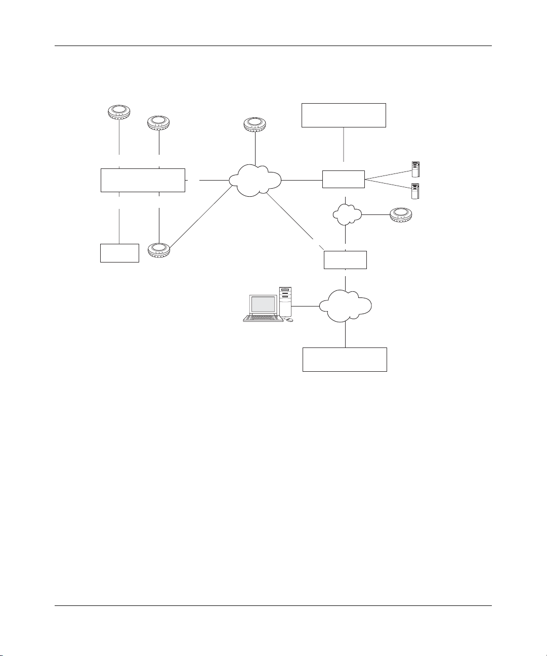
82 Configuring a 2370, 2360, or 2380 Switch for Basic Service
Figure 21. Example Nortel Network
serial-id 0322199997
AP-2330
Por t
1
Por t
3
Wired
authentication
client
VLANs on WSS1
VLAN 2 mgmt, port 5, 10.10.10.4/24
VLAN 4 blue, port 5, tag 20, 10.10.20.2/24
VLAN 3 red, port 5, tag 30
serial-id 0322199996
AP-2330
Por t
WSS1
System IP address
10.10.10.4
Por t
AP-2330
serial-id 0322199995
serial-id 0322199999
AP-2330
2
Por t
5
4
Layer 2
WMS
10.10.20.19/24
10.10.30.19/24
10.10.10.19/24
System IP address
10.10.40.4
WSS2
10.10.40.19/24
Router
10.10.60.19/24
Layer 2
10.10.60.18/24
Router
10.10.50.19/24
Layer 2
10.10.70.20
10.10.70.40
AP-2330
serial-id 0322199998
RADIUS
servers
WSS3
System IP address
10.10.50.4
Configuring an Enable Password
WSS Software does not require you to change the enable password from the default (null string). However,
Nortel recommends that you configure an enable password to provide at least minimal security to the WSS
before you proceed to more advanced configuration options.
To configure an enable password, use the following command:
set enablepass
To configure an enable password:
1 If you are not already at the enabled access level, enter the enable command.
2370> enable
2 At the enabled prompt, enter set enablepass.
2370# set enablepass
320656-A
Page 83
Configuring a 2370, 2360, or 2380 Switch for Basic Service 83
3 When you are prompted for your old password, press Enter.
Enter old password:
4 When you are prompted for a new password, enter an enable password of up to 32 alphanumeric
characters, with no spaces.
Enter new password:
The password you enter is not displayed.
5 When you are prompted to retype your password, reenter the enable password.
Retype new password:
WSS Software does not display your password, but lets you know that the enable password is set:
success: password changed
Configuring the Time and Date
To set the system time and date:
1 Set the time zone to specify the offset from Coordinated Universal Time (UTC).
2 Configure WSS Software to offset the time by an additional hour for daylight savings time or similar
summertime period, if applicable.
3 Specify the IP address of a Network Time Protocol (NTP) server or statically set the time and date.
Note. Nortel recommends that you set the time and date parameters before you install
certificates on the WSS. Generally, certificates are valid for one year beginning with the
system time and date that are in effect when you generate the certificate request. If the
switch’s time and date are incorrect, the certificate might not be valid.
To configure time and date parameters, use the following commands:
set timezone zone-name {-hours [minutes]}
set summertime summer-name [start week weekday month hour min end week weekday month
hour min]
set timedate {date mmm dd yyyy [time hh:mm:ss]}
set ntp {enable | disable}
set ntp server ip-addr
WLAN—Security Switch 2300 Series Installation and Basic Configuration Guide
Page 84

84 Configuring a 2370, 2360, or 2380 Switch for Basic Service
To verify the changes, use the following commands:
show timezone
show summertime
show timedate
show ntp
The following commands configure the timezone as PST (Pacific Standard Time) with an offset of -8 hours from UTC
and enable the standard summertime offset and name it PDT (Pacific Daylight Time). Additional commands configure
an NTP server and enable the WSS’s NTP client.
2370# set timezone PST -8
success: change accepted.
2370# set summertime PDT
success: change accepted.
2370# set ntp server 192.168.1.10
2370# set ntp enable
success: NTP Client enabled
The following commands display time and date parameters and the current time and date:
2370# show timezone
Timezone is set to 'PST', offset from UTC is -8:0 hours.
320656-A
2370# show summertime
Summertime is enabled, and set to 'PDT'.
Start : Sun Apr 04 2004, 02:00:00
End : Sun Oct 31 2004, 02:00:00
Offset : 60 minutes
Recurring : yes, starting at 2:00 am of first Sunday of April
and ending at 2:00 am on last Sunday of October.
2370# show ntp
NTP client: enabled
Current update-interval: 20(secs)
Current time: Fri Feb 06 2004, 12:02:57
Timezone is set to 'PST', offset from UTC is -8:0 hours.
Summertime is enabled.
Last NTP update: Fri Feb 06 2004, 12:02:46
NTP Server Peer state Local State
---------------------------------------------------
192.168.1.5 SYSPEER SYNCED
2370# show timedate
Fri Feb 06 2004, 12:03:04 PST
Page 85
Configuring a 2370, 2360, or 2380 Switch for Basic Service 85
Configuring IP Connectivity
To configure IP connectivity:
1 Configure a VLAN, assign a port to the VLAN that can provide IP connectivity through the network for
administrative purposes, and configure an IP address on the VLAN. (See “Configuring VLANs and IP
Addresses” on page 85.)
2 Configure a default route. (See “Configuring a Default Route” on page 87.)
3 Test the IP configuration. (See “Verifying IP Connectivity” on page 87.)
Configuring VLANs and IP Addresses
Any or all VLANs on the switch can have an IP address. WLAN Management Software and Web View require IP
connectivity to a WSS to manage the switch. User traffic also requires VLANs, although you do not need to configure
every user’s VLAN on every WSS. To configure a VLAN and an IP address, use the following commands:
set vlan vlan-num name name
set vlan vlan-id port port-list [tag tag-value]
set interface vlan-id ip {ip-addr mask | ip-addr/mask-length}
Note. The vlan-id parameter can be the VLAN number or the VLAN name.
To verify the changes, use the following commands:
show vlan config
show interface
The following commands configure a VLAN named mgmt and two additional VLANs over an 802.1Q trunk link for
network traffic:
2370# set vlan 2 name mgmt
success: change accepted.
2370# set vlan mgmt port 5
success: change accepted.
2370# set vlan 3 name red
success: change accepted.
2370# set vlan red port 5 tag 30
success: change accepted.
2370# set vlan 4 name blue
success: change accepted.
2370# set vlan blue port 5 tag 20
success: change accepted.
WLAN—Security Switch 2300 Series Installation and Basic Configuration Guide
Page 86

86 Configuring a 2370, 2360, or 2380 Switch for Basic Service
Note. To avoid confusion, do not assign numbers as VLAN names. Every VLAN on an
WSS has both a VLAN name used for authorization purposes and a VLAN number. VLAN
numbers can vary uniquely for each WSS and are not related to 802.1Q tag values even
when used. VLAN names must be unique among all WSSs in a Mobility Domain.
The following command displays VLAN information:
2370# show vlan config
Admin VLAN Tunl Port
VLAN Name Status State Affin Port Tag State
---- ---------------- ------ ----- ----- ---------------- ----- ---- 1 default Up Down 5
2 mgmt Up Down 5
5 none Up
3 red Up Down 5
5 30 Up
4 blue Up Down 5
5 20 Up
Note. The default VLAN listed in the sample show vlan output is present in a WSS’s
configuration by default but does not contain any ports unless you add them. Nortel
recommends that you do not use the default VLAN (VLAN 1) for user traffic or rename the
default VLAN. Instead, configure other VLANs and use those VLANs for user traffic. This is
because the default VLAN might not be in the same subnet on each switch.
The following commands configure IP addresses on some of the VLANs. (WSS Software does not require an
IP address on every VLAN.)
2370# set interface mgmt ip 10.10.10.4/24
success: change accepted.
2370# set interface blue ip 10.10.20.2/24
success: change accepted.
2370# show interface
VLAN Name Address Mask Enabled State RIB
---- --------------- --------------- --------------- ------- ----- ---------
2 mgmt 10.10.10.4 255.255.255.0 YES Up ipv4
4 blue 10.10.20.2 255.255.255.0 YES Up ipv4
320656-A
Page 87
Configuring a 2370, 2360, or 2380 Switch for Basic Service 87
Configuring a Default Route
If WLAN Management Software or Web View and a WSS are in different subnets, you need to configure a default route
on the WSS. To configure a default route, use the following command:
set ip route default gateway metric
To verify the change, use the following command:
show ip route
The following commands add a default route that uses gateway 10.10.20.19 with a path cost of 1, and verify the change:
2370# set ip route default 10.10.20.19 1
success: change accepted.
2370# show ip route
Router table for IPv4
Destination/Mask Proto Metric NH-Type Gateway VLAN:Interface
_________________ _______ ______ _______ _______________ _______________
0.0.0.0/ 0 Static 1 Router 10.10.20.19 vlan:4:ip
10.10.10.4/24 IP 0 Direct vlan:2:ip
10.10.10.4/32 IP 0 Local vlan:2:ip:10.10.10.4/24
10.10.10.255/32 IP 0 Local vlan:2:ip:10.10.10.4/24
10.10.20.2/24 IP 0 Direct vlan:4:ip
10.10.20.2/32 IP 0 Local vlan:4:ip:10.10.20.2/24
10.10.20.255/32 IP 0 Local vlan:4:ip:10.10.20.2/24
224.0.0.0/ 4 IP 0 Local MULTICAST
The 0.0.0.0 route is the default route. The 10.10.10.x and 10.10.20.x routes in this example are automatically added by
WSS Software when you configure the corresponding IP interfaces. The 224.0.0.0 route is for IGMP snooping. WSS
Software automatically places this route in the configuration.
Verifying IP Connectivity
To verify that the WSS can send and receive IP traffic, use the following command:
ping host
The ping command sends an Internet Control Message Protocol (ICMP) echo packet to the specified device and listens
for a reply packet. For host, specify the IP address of a host device on the network.
Note. If you configure the Domain Name Service (DNS) or set a local alias for the host
device, you can specify the DNS hostname or the alias instead of the IP address of the
device. (For information, see the WLAN 2300 System Software Configuration Guide.)
The following command verifies IP connectivity to IP address 10.10.20.19:
2370# ping 10.10.20.19
PING 10.10.20.19 (10.10.20.19) from 10.10.20.2 : 56(84) bytes of data.
64 bytes from 10.10.20.19: icmp_seq=1 ttl=255 time=0.769 ms
WLAN—Security Switch 2300 Series Installation and Basic Configuration Guide
Page 88

88 Configuring a 2370, 2360, or 2380 Switch for Basic Service
64 bytes from 10.10.20.19: icmp_seq=2 ttl=255 time=0.628 ms
64 bytes from 10.10.20.19: icmp_seq=3 ttl=255 time=0.676 ms
64 bytes from 10.10.20.19: icmp_seq=4 ttl=255 time=0.619 ms
64 bytes from 10.10.20.19: icmp_seq=5 ttl=255 time=0.608 ms
--- 20.20.20.1 ping statistics --5 packets transmitted, 5 packets received, 0 errors, 0% packet loss
Enabling Secure Communication for WLAN Management Software or Web View
To enable secure communication between WLAN Management Software or Web View and a WSS, install a
server certificate on the WSS. (See “Installing a Certificate” on page 90.)
For Web View, you also need to enable the HTTPS server on the switch and enable Transport Layer Security
(TLS) in the Web browser. (See “Enabling and Logging Into Web View” on page 97.)
Figure 22 shows an example of a WSS prepared for WLAN Management Software with certificate authority
(CA) certificates.
320656-A
Page 89
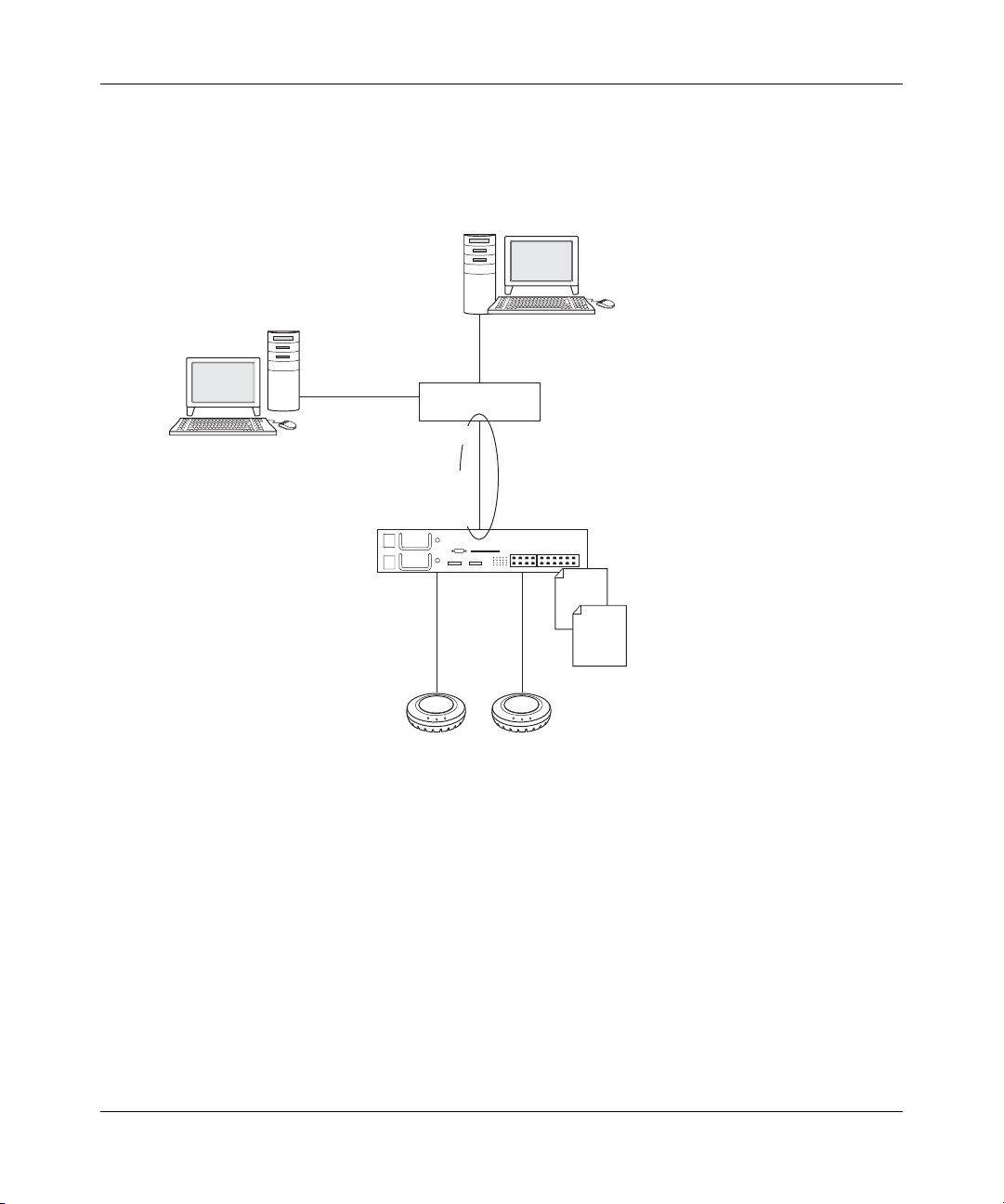
Configuring a 2370, 2360, or 2380 Switch for Basic Service 89
Figure 22. Secure WLAN Management Software Communication Using
CA Certificates
Certificate
authority
WMS
Router
10.10.10.19/24
VLAN 2 mgmt
Por t 5
10.10.10.4/24
WSSwitch
Server
certificate
Certificate
authority
certificate
AP
AP
840-9502-0045
WLAN—Security Switch 2300 Series Installation and Basic Configuration Guide
Page 90

90 Configuring a 2370, 2360, or 2380 Switch for Basic Service
Installing a Certificate
To manage a WSS, WLAN Management Software or a Web browser using Web View must be able to authenticate the switch and establish an encrypted session to it. This requires the switch to have a server certificate.
Use one of the following methods to enable secure communication between WLAN Management Software or
Web View and a WSS:
• Generate a self-signed certificate on the switch.
(See “Generating a Self-Signed Certificate” on page 90.)
• Alternatively, request a certificate for the WSS from a CA and install the certificate into the switch along
with the CA’s own certificate.
(See “Installing a Certificate Assigned by a Certificate Authority” on page 91 and “Installing a
Certificate Authority’s Certificate” on page 93.)
Generating a Self-Signed Certificate
As an alternative to using a certificate assigned by a CA, you can generate a self-signed certificate on the
WSS. To use a self-signed certificate generated by the WSS, use the following commands:
crypto generate key admin {512 | 1024 | 2048}
crypto generate self-signed admin
The following commands generate a public-private key pair and a self-signed certificate:
2370# crypto generate key admin 1024
key pair generated
2370# crypto generate self-signed admin
Country Name:
State Name:
Locality Name:
Organizational Name:
Organizational Unit:
Common Name: [email protected]
Email Address:
Unstructured Name:
Self-signed cert for admin is
-----BEGIN CERTIFICATE----MIICUzCCAbygAwIBAgICA+cwDQYJKoZIhvcNAQEEBQAwNjELMAkGA1UEBhMCVVMx
CzAJBgNVBAgTAkNBMRowGAYDVQQDFBF0ZWNocHVic0B0cnB6LmNvbTAeFw0wMzA0
...
Lm8wmVYLxP56MpCUAm9O8C2foYgOY40=
-----END CERTIFICATE-----
The common name is required. The other fields are optional. Use a common name that uniquely identifies the
WSS. Use a fully qualified name if such names are supported on your network.
320656-A
Page 91
Configuring a 2370, 2360, or 2380 Switch for Basic Service 91
WSS Software automatically installs the keys and self-signed certificate into its certificate and key store.
Note. When you select an option to import information from the WSS into WLAN
Management Software , it displays a dialog that shows the switch’s certificate information
and provides options for handling the certificate. You can configure WLAN Management
Software to always accept self-signed certificates from WSSs. (For more information, see
the Nortel WLAN Management Software Reference Manual.)
Installing a Certificate Assigned by a Certificate Authority
You can install a WSS certificate assigned by a CA in one of the following ways:
• Install a PKCS #12 object file—To use this method:
a Use TFTP to download onto the switch a PKCS #12 object file containing a public-private
key pair and a certificate assigned by the CA.
b Assign a one-time password to authenticate the PKCS #12 object file.
c Install the public-private key pair and certificate from the PKCS #12 object file into the
switch’s certificate and key store.
(For more information, see “Installing a Certificate from a PKCS #12 Object File” on page 91.)
• Install a PKCS #7 object file—To use this method:
a Generate a public-private key pair on the switch.
b Generate a certificate request on the switch.
c Use the request (a PKCS #10 object) to obtain a certificate from the CA.
d Install the certificate assigned by the CA (a PKCS #7 object file) into the switch’s
certificate and key store.
(For more information, see “Installing a Certificate from a PKCS #7 Object File” on page 92.)
In either case, you also need to install the CA’s own certificate on the switch and on the WLAN Management
Software or Web View host. The CA’s certificate allows WLAN Management Software or Web View to
verify that the switch certificate assigned by the CA is valid.
Note. Some certificate authorities refer to PKCS object files as base64 encoded files.
Installing a Certificate from a PKCS #12 Object File
To install a public-private key pair and a certificate assigned by a CA in a PKCS #12 object file, use the
following commands:
copy tftp://ip-addr/source-url [destination-url]
crypto otp admin string
crypto pkcs12 admin filename
WLAN—Security Switch 2300 Series Installation and Basic Configuration Guide
Page 92

92 Configuring a 2370, 2360, or 2380 Switch for Basic Service
These commands copy the PKCS #12 object file from a TFTP server to the WSS, configure a one-time password, and
install the PKCS #12 object file. The password allows the public-private key pair and the certificate to be installed
together from the same object file. WSS Software removes the password after completing the crypto pkcs12 command.
Here is an example:
2370# copy tftp://10.10.10.10/p12file
2370# crypto otp admin temppwd
2370# crypto pkcs12 admin p12file
Installing a Certificate from a PKCS #7 Object File
To generate a public-private key pair, and request and install a certificate assigned by a CA in a PKCS #7 object file, use
the following commands:
crypto generate key admin {512 | 1024 | 2048}
crypto generate request admin
crypto certificate admin PEM-formatted-certificate
The following commands generate a key pair and a certificate request:
2370# crypto generate key admin 1024
key pair generated
2370# crypto generate request admin
Country Name:
State Name:
Locality Name:
Organizational Name:
Organizational Unit:
Common Name: [email protected]
Email Address:
Unstructured Name:
CSR for admin is
-----BEGIN CERTIFICATE REQUEST----MIIBdTCB3wIBADA2MQswCQYDVQQGEwJVUzELMAkGA1UECBMCQ0ExGjAYBgNVBAMU
EXRlY2hwdWJzQHRycHouY29tMIGfMA0GCSqGSIb3DQEBAQUAA4GNADCBiQKBgQC4
...
2L8Q9tk+G2As84QYMwe9RJAjfbYM5bdWRUFiLzvK7BJgqBsCZz4DP00=
-----END CERTIFICATE REQUEST-----
The common name is required. The other fields are optional. Use a common name that uniquely identifies the WSS. Use
a fully qualified name if such names are supported on your network.
After you submit the certificate request to a CA and receive a signed certificate from the CA as a PKCS #7 object file,
install the certificate into the WSS’s certificate and key store:
1 Open the PKCS #7 object file with an ASCII text editor (such as Notepad) or a browser.
2 Type the crypto certificate admin command at the WSS’s prompt.
320656-A
Page 93
Configuring a 2370, 2360, or 2380 Switch for Basic Service 93
3 After the prompt, copy and paste the PKCS #7 object file into the CLI. For example:
2370# crypto certificate admin
Enter PEM-encoded certificate
-----BEGIN CERTIFICATE----MIIGDDCCBbagAwIBAgIKFrJ2aAAAAAAAnDANBgkqhkiG9w0BAQUFADCBm
zErMCkG
CSqGSIb3DQEJARYcYWRtaW5pc3RyYXRvckB0cmFwZXplc3FhLmNvbTELM
AkGA1UE
...
bDQNTaS4W0ytUGuJm1RjyA==
-----END CERTIFICATE-----
Note. You must paste the entire block, from the beginning:
-----BEGIN CERTIFICATE REQUEST----- to the end:
-----END CERTIFICATE REQUEST-----. The certificate server and WSS Software
recognize the block only through the beginning and ending delimiters.
Installing a Certificate Authority’s Certificate
In addition to installing the WSS certificate issued by the CA, you also need to install the CA’s own certificate
into the WSS switch’s certificate and key store. The CA certificate allows WLAN Management Software or
Web View to verify that the WSS’s certificate is valid. You need to install the CA’s certificate whether you
installed the switch certificate from a PKCS #7 object file or a PKCS #12 object file.
To install a CA’s certificate:
1 Request a copy of the CA certificate as a PKCS #7 object file from the CA, then open the file
with an ASCII text editor (such as Notepad) or a browser.
2 Type the crypto ca-certificate admin command.
3 After the prompt, copy and paste the PKCS #7 object file into the CLI. For example:
2370# crypto ca-certificate admin
Enter PEM-encoded certificate
-----BEGIN CERTIFICATE----MIIDwDCCA2qgAwIBAgIQL2jvuu4P05FAQICyewU3ojANBgkqhkiG9w0BA
QUFADCB
mzErMCkGCSqGSIb3DQEJARYcYWRtaW5pc3RyYXRvckB0cmFwZXplc3FhL
mNvbTEL
...
RGpOeQ==
-----END CERTIFICATE-----
WLAN—Security Switch 2300 Series Installation and Basic Configuration Guide
Page 94
94 Configuring a 2370, 2360, or 2380 Switch for Basic Service
Displaying Certificate Information
Use the following command to display administrative certificate information:
show crypto certificate admin
This command displays the following information about the certificate:
• X.509 version number
• Serial number
• Subject (the certificate holder’s identifying information)
• Signature algorithm used by the signer of the certificate
• Issuer information (CA information, unless the certificate is self-signed)
• Period during which the certificate is valid
Installing a Server Certificate for Network Users
To use an 802.1X authentication protocol that includes local EAP processing on a WSS, the switch must have
a server certificate. You can generate a certificate on the switch itself or install a certificate assigned by a
certificate authority (CA). If you use a certificate assigned by a CA, you also need to install the CA’s own
certificate for validation.
Note. If you use an authentication protocol that uses EAP-TLS on the WSS, users also
need certificates. (For more information, see the Nortel Mobility System Software
Configuration Guide.)
The command syntax for installing certificates for management by WLAN Management Software or Web
View and installing certificates for network users is very similar. The CLI commands for configuring network
user authentication use the eap option instead of the admin option, but are otherwise the same. Likewise, the
procedures are the same.
320656-A
Page 95

Configuring a 2370, 2360, or 2380 Switch for Basic Service 95
Generating a Self-Signed Certificate for Network Users
As an alternative to using a certificate assigned by a CA, you can generate a self-signed certificate on the
WSS. To use a self-signed certificate, use the following commands:
crypto generate key eap {1024 | 2048}
crypto generate self-signed eap
The common name is required. The other fields are optional. WSS Software automatically installs the key and
self-signed certificate into its certificate and key store.
Installing a Certificate Assigned by a Certificate Authority for Network Users
You can install a certificate assigned by a CA in one of the following ways:
• Install a PKCS #12 object file
• Install a PKCS #7 object file
In either case, you also need to install the CA’s own certificate. The CA certificate allows users to verify that
the switch certificate assigned by the CA is valid.
Installing a Certificate for Network Users from a PKCS #12 Object File
To install a public-private key pair and a certificate assigned by a CA in a PKCS #12 object file, use the
following commands:
copy tftp://ip-addr/source-url [destination-url]
crypto otp eap string
crypto pkcs12 eap filename
These commands copy the PKCS #12 object file from a TFTP server to the WSS, configure a one-time
password, and install the PKCS #12 object file. The password allows the public-private key pair and the certificate to be installed together from the same object file. WSS Software removes the password after completing
the crypto pkcs12 command.
Installing a Certificate for Network Users from a PKCS #7 Object File
To generate a public-private key pair, and request and install a certificate assigned by a CA in a PKCS #7
object file, use the following commands:
crypto generate key eap {1024 | 2048}
crypto generate request eap
crypto certificate eap PEM-formatted-certificate
WLAN—Security Switch 2300 Series Installation and Basic Configuration Guide
Page 96
96 Configuring a 2370, 2360, or 2380 Switch for Basic Service
After you submit the certificate request to a CA and receive a signed certificate from the CA as a PKCS #7
object file, install the certificate into the WSS’s certificate and key store:
1 Open the PKCS #7 object file with an ASCII text editor (such as Notepad).
2 Type the crypto certificate eap command at the WSS’s command prompt.
3 After the prompt, paste the PKCS #7 object file into the CLI. For example:
2370# crypto certificate eap
Enter PEM-encoded certificate
-----BEGIN CERTIFICATE----MIIGDDCCBbagAwIBAgIKFrJ2aAAAAAAAnDANBgkqhkiG9w0BAQUFADCBm
zErMCkG
CSqGSIb3DQEJARYcYWRtaW5pc3RyYXRvckB0cmFwZXplc3FhLmNvbTELM
AkGA1UE
...
bDQNTaS4W0ytUGuJm1RjyA==
-----END CERTIFICATE-----
Note. You must paste the entire block, from the beginning:
-----BEGIN CERTIFICATE REQUEST----- to the end:
-----END CERTIFICATE REQUEST-----. The certificate server and WSS Software
recognize the block only through the beginning and ending delimiters.
Installing a Certificate Authority’s Certificate for Network Users
In addition to installing the WSS certificate issued by the CA, you also need to install the CA’s own certificate
into the WSS’s certificate and key store. The CA certificate allows users to verify that the WSS’s certificate is
valid. You need to install the CA’s certificate whether you installed the switch certificate from a PKCS #7
object file or a PKCS #12 object file.
To install a CA’s certificate:
1 Request a copy of the CA certificate as a PKCS #7 object file from the CA, then open the file
with an ASCII text editor (such as Notepad).
2 Type the crypto ca-certificate eap command.
3 After the prompt, paste the PKCS #7 object file into the CLI. For example:
2370# crypto ca-certificate eap
Enter PEM-encoded certificate
-----BEGIN CERTIFICATE----MIIDwDCCA2qgAwIBAgIQL2jvuu4P05FAQICyewU3ojANBgkqhkiG9w0BA
QUFADCB
mzErMCkGCSqGSIb3DQEJARYcYWRtaW5pc3RyYXRvckB0cmFwZXplc3FhL
mNvbTEL
...
RGpOeQ==
320656-A
Page 97

Configuring a 2370, 2360, or 2380 Switch for Basic Service 97
-----END CERTIFICATE-----
Displaying Certificate Information for Network Users
Use the following command to display certificate information for network users:
show crypto certificate eap
Enabling and Logging Into Web View
Use the procedure in this section if you plan to use Web View to continue configuring the switch. Otherwise, skip this
section and go to “Specifying the Country of Operation”.
Web View uses Hypertext Transfer Protocol over Secure Sockets Layer (HTTPS), which requires TLS. To use Web
View:
• Enable the HTTPS server on the WSS.
• Enable TLS 1.0, SSL 2.0, or SSL 3.0 in the Web browser.
To enable the HTTPS server on the WSS, type the following command:
set ip https server enable
To enable TLS 1.0, SSL 2.0, or SSL 3.0 in Microsoft Internet Explorer:
1 Select Tools > Internet Options to display the Internet Options dialog box.
2 Select the Advanced tab.
3 Scroll to the bottom of the list of options and select the TLS 1.0, SSL 2.0, or SSL 3.0 option to enable it.
4 Click OK.
To log in to a WSS with Web View:
1 Type https://ip-addr in the Web browser’s Address or Location field and press Enter.
For ip-addr, type an IP address you configured on the switch. (See “Configuring VLANs and IP
Addresses” on page 85.)
2 In the Password field, type the enable password you configured on the switch.
(See “Configuring an Enable Password” on page 82.)
Leave the User name field blank.
3 Click OK.
Note. If your web browser has the Google toolbar installed, one of the toolbar’s options
can cause some of the fields in Web View to be highlighted in yellow. If you want to turn off
the yellow highlighting, disable the Automatically highlight fields that Autofill can fill
option, which is one of the toolbar’s options.
WLAN—Security Switch 2300 Series Installation and Basic Configuration Guide
Page 98

98 Configuring a 2370, 2360, or 2380 Switch for Basic Service
Specifying the Country of Operation
You must specify the country in which you plan to operate the WSS and its AP access points. WSS Software does not
allow you to configure or enable the AP access point radios until you specify the country of operation.
Note. If you plan to upload the WSS’s configuration into WLAN Management Software
(with the Changes > Upload WLAN—Security Switch option), you must specify the
country of operation with the CLI before uploading the configuration. If the country of
operation is not specified, WLAN Management Software rejects the configuration.
To specify the country, use the following command:
set system countrycode code
For the country code, specify one of the codes listed in Table 8.
Table 8: Country Codes
Country Code
Australia AU
Austria AT
Belgium BE
Brazil BR
Canada CA
China CN
Czech Republic CZ
Denmark DK
Finland FI
France FR
Germany DE
Greece GR
Hong Kong HK
Hungary HU
Iceland IS
India IN
Ireland IE
Israel IL
Italy IT
320656-A
Page 99

Configuring a 2370, 2360, or 2380 Switch for Basic Service 99
Table 8: Country Codes (continued)
Country Code
Japan JP
Liechtenstein LI
Luxembourg LU
Malaysia MY
Mexico MX
Netherlands NL
New Zealand NZ
Norway NO
Poland PL
Portugal PT
Saudi Arabia SA
Singapore SG
Slovakia SK
Slovenia SI
South Africa ZA
South Korea KR
Spain ES
Sweden SE
Switzerland CH
Tai wan TW
Thailand TH
United Arab Emirates AE
United Kingdom GB
United States US
To verify the configuration change, use the following command:
show system
The following example sets the country code to US (United States) and verifies the setting:
2370# set system countrycode US
success: change accepted.
2370# show system
===============================================================================
Product Name: 2370
WLAN—Security Switch 2300 Series Installation and Basic Configuration Guide
Page 100

100 Configuring a 2370, 2360, or 2380 Switch for Basic Service
System Name: 2370
System Countrycode: US
System Location:
System Contact:
System Description: 2370
System IP: 0.0.0.0
System MAC: 00:0B:0E:02:76:F6
===============================================================================
Boot Time: 2003-05-07 08:28:39
Uptime: 0 days 04:00:07
===============================================================================
Fan status: fan1 OK fan2 OK fan3 OK
Temperature: temp1 ok temp2 ok temp3 ok
PSU Status: Lower Power Supply DC ok AC ok Upper Power Supply missing
Memory: 115.09/496.04 (23%)
Total Power Over Ethernet : 32.000
===============================================================================
Specifying a System IP Address
You can designate one of the IP addresses configured on a WSS’s VLAN to be the system IP address of the
switch. The system IP address provides a common IP interface and source IP address for some Nortel management and Mobility Domain operations. The system IP address is required by some features, including
roaming. The system IP address is also used by default for other features, including RADIUS and the system
log.
To assign one of the configured IP addresses to be the system IP address, use the following command:
set system ip-address ip-addr
Enter an IP address in dotted decimal notation. This command sets the IP address you specify to be the system
IP address.
To verify the configuration change, use the following command:
show system
The following commands configure the system IP address to be 10.10.10.4, the IP address on VLAN mgmt,
and verify the change:
2370# set system ip-address 10.10.10.4
success: change accepted.
2370# show system
===============================================================================
Product Name: 2370
System Name: 2370
System Countrycode:
System Location:
System Contact:
System Description: 2370
System IP: 10.10.10.4
System MAC: 00:0B:0E:02:76:F6
===============================================================================
Boot Time: 2003-05-07 08:28:39
320656-A
 Loading...