

Page 1

Title page
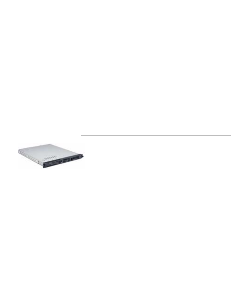
Nortel Application Gateway 2000
Nortel Application Gateway Release 6.2
Hardware Installation Guide
Installation
Document Number: NN42360-303
Document Release: Standard 02.01
Date: January 2008
Year Publish FCC TM
Copyright © 2008 Nortel Networks. All Rights Reserved.
Sourced in Canada
LEGAL NOTICE
While the information in this document is believed to be accurate and reliable, except as otherwise expressly
agreed to in writing NORTEL PROVIDES THIS DOCUMENT "AS IS" WITHOUT WARRANTY OR CONDITION
OF ANY KIND, EITHER EXPRESS OR IMPLIED. The information and/or products described in this document
are subject to change without notice.
Nortel, the Nortel logo, the Globemark, SL-1, Meridian 1, and Succession are trademarks of Nortel Networks.
All other trademarks are the property of their respective owners.
Page 2

Page 3

Contents
Preface v
Audience v
Organization v
Conventions vi
Related Documentation vi
Online Documentation vii
CHAPTER
CHAPTER
1 Application Gateway Overview 1
Power 2
Connectors 3
Front Controls, LEDs, and CD Drive 3
Back Connectors 5
Rear LEDs 6
Specifications, Safety, and Other Information 6
2 Hardware Installation and Initial Configuration 7
Readiness Checklist 7
Materials Required 8
Rack Mounting 9
Connecting and Powering up the Application Gateway 9
Alternate Procedure if Using a Crossover Cable 13
Licensing 15
Obtaining a Keycode License 15
Installing Licenses 16
Third-Party Software 17
Application Gateway Hardware Installation Guide
iii
Page 4

Contents
iv
Application Gateway Hardware Installation Guide
Page 5

Preface
This preface describes who should read the Application Gateway Hardware
Installation Guide, how it is organized, and its document conventions.
Audience
This installation guide is intended for service technicians who will install
the Application Gateway 2000.
Organization
This guide is organized as follows:
Chapter Title Description
Chapter 1 Application Gateway
Overview
Chapter 2 Hardware Installation
and Initial Configuration
Describes the server and its connectors.
Contains pre-installation, installation, and
initial configuration procedures.
Application Gateway Hardware Installation Guide
v
Page 6

Conventions
Conventions
This guide uses the following conventions:
Convention Description
boldface font Commands and HTML element names are in
boldface screen
font
Notes use the following conventions:
Note Means reader take note. Notes contain helpful suggestions or other
important information.
Tips use the following conventions:
Tip Means the following information will help you solve a problem. The tips
information might not be troubleshooting or even an action, but could be
useful information.
boldface.
Information you must enter is in boldface screen
font.
Cautions use the following conventions:
Caution Means reader be careful. In this situation, you might do
something that could result in equipment damage or loss of
data.
Related Documentation
For additional information about the Application Gateway, refer to these
guides:
• Application Gateway Administration Guide
• Application Gateway Release Notes
vi
Application Gateway Hardware Installation Guide
Page 7

Online Documentation
To access Nortel documentation online, click the
Technical Documentation link under Support on the Nortel home page:
http://www.nortel.com/
Online Documentation
Application Gateway Hardware Installation Guide
vii
Page 8

Online Documentation
viii
Application Gateway Hardware Installation Guide1Application Gateway Hardware Installation Guide
Page 9
Chapter
Nortel Application Gateway 2000
Chapter
1
Application Gateway Overview
Note The Application Gateway 2000 is an appliance containing software
and an IBM xSeries 306m server. The IBM documentation that is
shipped with the IBM server includes rack mounting instructions,
physical specifications, safety information, and operating and
environmental information. The Application Gateway 2000 is not
user-serviceable, therefore the IBM documentation that covers
tasks such as opening the server and replacing parts do not apply
to the Application Gateway. Defective Application Gateways
should be returned to Nortel.
The Nortel Application Gateway 2000 delivers business
applications to the screens and speakers of Nortel IP
telephones. The applications delivered to Nortel IP Phones
and other devices include Nortel Voice Office applications
and Nortel Guest Services.
The location of an Application Gateway in a network is largely based on
the configuration of the existing network. The flexible deployment of the
Application Gateway enables you to connect it to application servers,
routers, firewalls, and switches. For information on integrating
Application Gateways into your network, refer to the Application Gateway
Network Integration Guide.
The following topics provide an overview to the physical components of
the Application Gateway:
• Power, page 2
• Connectors, page 3
• Specifications, Safety, and Other Information, page 6
Page 10

Chapter 1 Application Gateway Overview
Power
Power
The power cord connector is located on the left side on the back of the
Application Gateway. When the power LED, on the front panel, is
illuminated, the power is on.The power control button is on the front
panel. The power supplies are factory installed and not customer
replaceable.
Attention: This server is suitable for use on an IT power distribution
system, whose maximum phase to phase voltage is 240 V under any
distribution fault condition.
The following table lists the current RoHS and non-RoHS cords for the IP
Phone Global Power Supply.
CPC
(RoHS) PEC (RoHS)
N0089601 NTYS17AAE6 N0023000 N0023000 IP Phone Global
N0089603 NTYS14AAE6 N0066566 NTYS14AA Standard IEC Cable
N/A N/A A0781922 NTTK15AA Standard IEC Cable
N0114986 NTTK16ABE6 A0506456 NTTK16AB Standard IEC Cable
N0109787 NTTK17ABE6 A0506461 NTTK17AB Standard IEC Cable
N0109881 NTTK18ABE6 A0506464 NTTK18AB Standard IEC Cable
N0109788 NTTK22ABE6 A0506468 NTTK22AB Standard IEC Cable
N/A N/A A0814961 A0814961 Standard IEC Cable
N0118951 NTTK26AAE6 None None Standard IEC Cable
CPC
(Non-RoHS)
PEC
(Non-RoHS) Description
Power Supply
(200x and 1100)
(RoHS)
- North America
- Australia / NZ
- Europe
- Switzerland
- UK
- Denmark
- Argentina
- Japan
2
Application Gateway Hardware Installation Guide
Page 11

Connectors
The following topics describe the Application Gateway connectors:
• Front Controls, LEDs, and CD Drive, page 3
• Back Connectors, page 5
Front Controls, LEDs, and CD Drive
Figure 1 shows the front of the Application Gateway.
Figure 1 Application Gateway Front Controls, LEDs, and CD Drive
Chapter 1 Application Gateway Overview
Connectors
Power-on LED: When this LED is lit, it indicates that the server is turned
on. When this LED is off, it indicates that ac power is not present, or the
power supply or the LED itself has failed.
Note If this LED is off, it does not mean that there is no electrical power
in the server. The LED might be burned out. To remove all
electrical power from the server, you must disconnect the power
cord from the electrical outlet.
Power-control button: Press this button to turn the server on and off
manually. A power-control-button shield comes installed around the
button to prevent the server from being turned off accidentally. You can
remove this disk-shaped shield if you prefer.
Application Gateway Hardware Installation Guide
3
Page 12

Chapter 1 Application Gateway Overview
Connectors
Reset button: Press this button to reset the server and run the power-on
self-test (POST). You might have to use a pen or the end of a straightened
paper clip to press the button.
Hard disk drive activity LED: When this LED is flashing, it indicates that
a hard disk drive is in use.
Locator LED: When this LED is lit, it has been lit remotely by the system
administrator to aid in visually locating the server.
System-error LED: When th is LED is lit , it ind icate s that a syste m erro r has
occurred.
USB connectors: Connect a USB device to either of these connectors.
CD-eject button: Press this button to release a CD from the CD drive. The
CD drive is used to restore the Application Gateway server software in the
event of a system failure.
CD drive activity LED: When this LED is lit, it indicates that the CD drive
is in use.
4
Application Gateway Hardware Installation Guide
Page 13

Back Connectors
Figure 2 shows the back of the Application Gateway.
Figure 2 Connectors on the back of the Application Gateway
Power-cord connector: Connect the power cord to this connector.
Serial connector: The DB-9 serial port is used to connect the Application
Gateway to a computer that is capable of running terminal emulation
software. This connection is used to access the Application Gateway Serial
Console during initial configuration.
Chapter 1 Application Gateway Overview
Connectors
Ethernet connectors: Typically, you connect Ethernet 2 network interface
(Interface 0) to the ELAN.
However, if the Application Gateway straddles two networks, use both
interfaces as follows:
• The Ethernet 1 network interface (Interface 1) connects the
Application Gateway to the server-side network, directly or indirectly.
• The Ethernet 2 network interface (Interface 0) connects the
Application Gateway to the client-side network.
Other connectors: These are not used for any function. Do not plug any
device into these connectors.
Application Gateway Hardware Installation Guide
5
Page 14

Chapter 1 Application Gateway Overview
Specifications, Safety, and Other Information
Rear LEDs
Figure 3 shows the LEDs on the back of the Application Gateway.
Figure 3 LEDs on the back of the Application Gateway
Ethernet transmit/receive activity LED: This LED is on each Ethernet
connector. When this LED is lit, it indicates that there is activity between
the server and the network.
Ethernet speed LED: This LED is on each Ethernet connector. When this
LED is lit, it indicates that the Ethernet network speed is 1 Gbps. When this
LED is off, it indicates that the Ethernet network speed is 10 Mbps or 100
Mbps.
Specifications, Safety, and Other Information
For documentation specific to the IBM xSeries server, such as physical
specifications, safety information, rack mounting instructions, and
operating and environmental specifications, refer to the printed
information provided by IBM as well as the IBM xSeries Documentation
CD (provided with the server).
6
Application Gateway Hardware Installation Guide
Page 15

Chapter
Chapter
2
Hardware Installation and Initial Configuration
The following topics describe how to connect the Nortel Application
Gateway 2000 to the network and perform initial configuration:
• Readiness Checklist, page 7
• Materials Required, page 8
• Rack Mounting, page 9
• Connecting and Powering up the Application Gateway, page 9
• Licensing, page 15
Readiness Checklist
Before starting the installation, complete the checklist in Table 1.
Table 1 Readiness checklist (Sheet 1 of 2)
Have you: ✓
Read all safety instructions in the IBM xSeries 306m server
documentation?
Received all equipment?
Made sure the area meets all environmental requirements?
Checked for all power requirements?
Checked for correct grounding facilities?
Application Gateway Hardware Installation Guide
7
Page 16

Chapter 2 Hardware Installation and Initial Configuration
Materials Required
Table 1 Readiness checklist (Sheet 2 of 2)
Have you: ✓
Obtained the following:
• screwdrivers
• an ECOS 1023 POW-R-MATE or similar type of
multimeter
• appropriate cable terminating tools
• a computer to be connected directly to the Application
Gateway by a DTE—DTE null modem cable, with a
teletype terminal (ANSI-W emulation, serial port,
19 200 bps) for the Application Gateway. Alternatively,
a crossover cable and PC.
Determined the network location for the Application
Gateway? For information, refer to the Application Gateway
Network Integration Guide.
Completed the Application Gateway Pre-Installation
Checklist?
Materials Required
To install the Application Gateway, obtain the following items:
1. The Application Gateway and its installation CD-ROM.
Note Save the packaging container and packing materials in case you
must reship the product.
2. The power cable for the Application Gateway. Check that the power
cord is the exact type required in the host region. Do not modify or use
the supplied AC power cord if it is not the correct type.
3. The serial cable for the Application Gateway. Alternatively, a
crossover cable.
4. The CAT5 cables for networking.
8
Application Gateway Hardware Installation Guide
Page 17

Chapter 2 Hardware Installation and Initial Configuration
Rack Mounting
You will need one network cable to connect the Application Gateway
to a LAN or two cables if the Application Gateway will straddle two
networks.
Rack Mounting
Refer to the IBM Rack Installation Instructions provided with the server.
Connecting and Powering up the Application Gateway
WAR NING
Do not modify or use a supplied AC power cord
if it is not the exact type required in the region
where the Application Gateway is installed and
used.
Be sure to replace the cord with the correct type.
In geographic regions that are susceptible to electrical storms, Nortel
recommends that you plug the Application Gateway into an AC surge
suppressor.
The default IP address of the Application Gateway is 10.20.30.40, with a
netmask of 255.255.0.0. You will likely need to change that default address
to match your network scheme. You can either use the serial console
interface or the Web-based Administration Tool to change the IP address.
Note Use the procedure in this section if you will use a serial console to change
the Application Gateway network settings. To use the Web-based
interface, see “Alternate Procedure if Using a Crossover Cable,” page 13.
To connect and power up the Application Gateway:
1 Connect the Application Gateway to the network.
Application Gateway Hardware Installation Guide
9
Page 18

Chapter 2 Hardware Installation and Initial Configuration
Serial Cable
Maintenance Terminal
Application Gateway
Connecting and Powering up the Application Gateway
• If the Application Gateway can access the connected device (router,
application server, etc.) from the same subnet as it receives client
requests, use one network cable. Connect Application Gateway
interface port 0 (ethernet 2) to your network. This is the typical
configuration.
• If the Application Gateway will straddle two networks, use two
network cables:
–
Connect Application Gateway Interface 0 (ethernet 2) to the
client-side network.
–
Connect Application Gateway Interface 1 (ethernet 1) to the
server-side network, directly or indirectly.
The two network interfaces are shown in Figure 4.
Figure 4 Ethernet Port Connectors
10
Application Gateway Hardware Installation Guide
2
Connect a maintenance terminal to the Application Gateway.
a. Connect a DTE–DTE null modem serial cable (supplied with the
Application Gateway) from the Serial Port on the back of the
Application Gateway to a maintenance terminal. The connection looks
like that shown in Figure 5.
Figure 5 Application Gateway connection to Terminal
Page 19

Chapter 2 Hardware Installation and Initial Configuration
Connecting and Powering up the Application Gateway
b.
Set the COM port on the maintenance terminal as follows:
• Terminal type: VT100
• Speed: 19200
• Data bits: 8
• Parity: none
• Stop bits: 1
• Flow control: hardware
Note The Application Gateway is shipped with the Admin/Serial port
set to 19200 Bit/s.
3 Connect the Application Gateway power cord.
a. Check that the power cord is the type required in the region where the
Application Gateway is used.
Do not modify or use the supplied AC power cord if it is not the
correct type. Refer to Installation and Configuration guide for your
call server for a detailed power cord description.
b. Attach the female end of the power cord to the AC power receptacle
on the left side of the Application Gateway back panel. See Figure 2 on
page 5. Plug the male end of the AC power cord into the AC power
source (wall outlet).
4 Press the power switch on the front of the Application Gateway to start it.
5 Quickly insert the Application Gateway CD-ROM into the CD-ROM drive
after you power it up.
After several minutes, the Application Gateway Serial Console appears on
the maintenance terminal. If you see garbage characters, verify that the
baud rate of the terminal emulator is set to 19200.
The message “Installation Successful” appears after the installation
completes.
6 Eject the CD-ROM and reboot the Application Gateway.
You are now ready to configure the Application Gateway with your
network.
Application Gateway Hardware Installation Guide
11
Page 20

Chapter 2 Hardware Installation and Initial Configuration
Connecting and Powering up the Application Gateway
To configure the Application Gateway using a serial console:
1 In the Application Gateway serial console, enter the default login root and
the default password rootadmin.
2 Type 0 and press Enter to choose Express Setup.
3 Enter the IP address and netmask for Interface 0 when prompted.
Note The Application Gateway does not work with Dynamic Host
Configuration Protocol (DHCP). You must use static IP addresses
for the Application Gateway.
4 Enter the IP address of the gateway device when prompted.
A list of the settings displays.
5 Verify that the settings are correct.
If they are correct, type y when asked to commit your changes. The
Application Gateway restarts and displays the login prompt.
If they are not correct, type n when asked to commit your changes, then
type 0 (Express Setup) to change settings.
12
6 To test the connection, verify that the Application Gateway can ping
connected network devices: Type 1 (Ping), press Enter, and enter the IP
address that you want to ping.
If the ping is successful, you have completed the initial configuration. If
the ping is not successful, check your connections, return to the serial
console Main Menu, and type 0 (Express Setup) to change settings as
needed.
7 Install licenses as described in “Installing Licenses,” page 16.
Refer to the Application Gateway Administration Guide for additional
operating information. You can download all documentation from the
Application Gateway Administration Tool.
Application Gateway Hardware Installation Guide
Page 21

Chapter 2 Hardware Installation and Initial Configuration
Connecting and Powering up the Application Gateway
Alternate Procedure if Using a Crossover Cable
If you prefer to use the Web-based Administration Tool rather than a serial
console to change the network settings of the Application Gateway, follow
the procedure described in this topic. You can use this procedure to
perform the initial installation or to change the network settings after
installation is completed.
1 Connect the power cord to the AC power receptacle.
a. Check that the power cord is the type required in the region where the
Application Gateway is used.
Do not modify or use the supplied AC power cord if it is not the
correct type. Refer to Installation and Configuration guide for your
call server for a detailed power cord description.
b. Attach the female end of the power cord to the AC power receptacle
on the left side of the Application Gateway back panel. See Figure 2 on
page 5. Plug the male end of the AC power cord into the AC power
source (wall outlet).
2 If the Application Gateway is not already installed, insert the Application
Gateway CD-ROM into the CD-ROM drive.
3 Press the power switch on the front of the Application Gateway to start it.
Power on the personal computer that you will connect to it.
4 Connect the Ethernet crossover cable to an Ethernet port on your personal
computer and to the interface port 0 (ethernet 2) of the Application
Gateway.
5 Change the IP address of your pers onal compu t e r so that you can establish
a point-to-point subnet between it and the Application Gateway:
a. On your personal computer, right-click Network Places and choose
Properties.
b. In the Network Connections window, right-click Local Area
Connection and choose Properties.
c. On the General tab, select Internet Protocol (TCP/IP) and click
Properties.
d. On the General tab of the Internet Protocol dialog box, select Use the
following IP address.
e. Enter the IP address 10.20.30.4x, where x is a digit from one to nine.
Application Gateway Hardware Installation Guide
13
Page 22

Chapter 2 Hardware Installation and Initial Configuration
Connecting and Powering up the Application Gateway
f. Enter the Subnet Mask 255.255.0.0.
g. Enter the Default Gateway and click OK twice.
6 Change the Application Gateway network settings:
a. From a web browser on the connected PC, enter
https://10.20.30.40:9001 to access the Application Gateway
Administration Tool.
b. If a Security Alert dialog box appears, click Yes.
c. Click the Network tab, log in as root, and enter the root password
(defaults to rootadmin).
d. On the Network > Interfaces page, enter the IP address and netmask
for Interface 0 and the IP address of the gateway device.
e. Click Submit to save your changes. Close the Administration Tool.
7 Disconnect the Ethernet crossover cable from the Application Gateway.
8 Connect the 10/100 RJ45 NIC connectors located on the Application
Gateway back panel as follows.
• If the Application Gateway can access the connected device (router,
application server, etc.) from the same subnet as it receives client
requests, use one network cable. Connect Application Gateway
interface port 0 (ethernet 2) to your network. This is the typical
configuration.
14
• If the Application Gateway will straddle two networks, use two
network cables:
–
Connect Application Gateway Interface 0 (Ethernet 2) to the
client-side network.
–
Connect Application Gateway Interface 1 (Ethernet 1) to the
server-side network, directly or indirectly.
The two network interfaces are shown in Figure 4.
Application Gateway Hardware Installation Guide
Page 23

Licensing
Chapter 2 Hardware Installation and Initial Configuration
Licensing
Figure 6 Ethernet Port Connectors
Remove the CD-ROM and restart the Application Gateway.
9
10 Install licenses as described in “Installing Licenses,” page 16.
Refer to the Application Gateway Administration Guide for additional
operating information. You can download all documentation from the
Application Gateway Administration Tool.
To license your Application Gateway, you will first need to obtain a
keycode license, then upload the license onto Application Gateway server
using the Administration Tool.
• Obtaining a Keycode License, page 15
• Installing Licenses, page 16
Obtaining a Keycode License
Keycode Licensing for your product is provided by the Nortel KRS
(Keycode Retrieval System). In order for you to use the KRS you must first
be a registered user of the KRS. To register for an account please use the
following link http://www.nortel.com/servsup/krs/
Online registration process.
Note Please allow up to 5 business days for your request to be processed.
Once you have received confirmation that your KRS account is enabled,
you can log into the KRS production system by once again using the URL
http://www.nortel.com/servsup/krs/.
and in Step 2, select the product you wish to access. In this case choose
Application Gateway.
and complete the
In Step 1, select the login region
Application Gateway Hardware Installation Guide
15
Page 24

Chapter 2 Hardware Installation and Initial Configuration
Licensing
Once you have logged into the KRS you will need the following
information in order to produce your keycode license:
• The MAC address of the server you want to license (i.e.
00:00:00:00:00:00 )
• The Purchase Order number or Nortel Order number (this is so you
can locate your order which will list the software licensing items
ordered).
After logging into the KRS you will perform the following steps to
generate your keycode license.
Note On KRS there is a User Guide which provides detailed information for
each of these steps.
1 You must first register the server you intend to license in the KRS
database. This is where you will need the MAC address of your server.
2 Once the server is registered you can elect to Generate Keycode License
with Purchase Order. You simply select this function from the sidebar.
3 Enter the MAC address for which you want to produce a keycode license
at the prompt.
4 Enter your Purchase Order number or Nortel Order number at the
prompt.
5 The Purchase Order will be displayed. Select which line items you wish to
use in producing the Keycode license (typically, this will be all line items).
6 Review the summary of the features selected and if correct to click
Generate Keycode License.
7 The KRS produces the Keycode License, saves it in its database and
provides you with the option of downloading the keycode license to your
computer.
Installing Licenses
To upload license files to the Application Gateway:
1 In the Administration Tool, go to the Administration > Licenses page.
2 Across from Upload License File, click Browse and locate the .lic file that
you want to upload.
16
Application Gateway Hardware Installation Guide
Page 25

3
Click Open and then click Upload.
You will be prompted to reboot. You do not have to reboot until you have
uploaded all license files.
When you save the Application Gateway configuration (Administration >
Maintenance), license information is included in the backup file.
To view the number of available licenses:
• In the Administration Tool, go to the Administration > Licenses page.
Note To complete the Application Gateway configuration, refer to the
Application Gateway Administration Guide.
Third-Party Software
We recommend that you not install any third-party software on the
Application Gateway. Problems caused by the installation of third-party
software are not supported.
Chapter 2 Hardware Installation and Initial Configuration
Licensing
Application Gateway Hardware Installation Guide
17
Page 26

Chapter 2 Hardware Installation and Initial Configuration
Licensing
18
Application Gateway Hardware Installation Guide
Page 27

Page 28

Family Product Manual Contacts Copyright FCC notice Trademarks Document number
Product release Document release Date Publish
Nortel Application Gateway 2000
Hardware Installation Guide
Installation
Copyright © 2008 Nortel Networks. All Rights Reserved.
LEGAL NOTICE
While the information in this document is believed to be accurate
and reliable, except as otherwise expressly agreed to in writing
NORTEL PROVIDES THIS DOCUMENT "AS IS" WITHOUT
WARRANTY OR CONDITION OF ANY KIND, EITHER
EXPRESS OR IMPLIED. The information and/or products
described in this document are subject to change without notice.
Nortel, the Nortel logo, the Globemark, SL-1, Meridian 1, and
Succession are trademarks of Nortel Networks.
All other trademarks are the property of their respective owners.
Publication number: NN42360-303
Document release: Standard 02.01
Date: January 2008
Sourced in Canada
To provide feedback or report a problem in this document, go to
www.nortel.com/documentfeedback.
 Loading...