

Page 1

Version 7.00
Part No. NN46110-500
311642-M Rev 01
February 2007
Document status: Standard
600 Technology Park Drive
Billerica, MA 01821-4130
Nortel VPN Router
Configuration — Basic
Features
Page 2

2
NN46110-500
Copyright © 2007 Nortel Networks. All rights reserved.
The information in this document is subject to change without notice. The statements, configurations, technical data, and
recommendations in this document are believed to be accurate and reliable, but are presented without express or implied
warranty. Users must take full responsibility for their applications of any products specified in this document. The
information in this document is proprietary to Nortel Networks Inc.
The software described in this document is furnished under a license agreement and may be used only in accordance
with the terms of that license. The software license agreement is included in this document.
TrademarksNortel
Nortel Networks, the Nortel Networks logo, and Nortel VPN Router are trademarks of Nortel Networks.
Adobe and Acrobat Reader are trademarks of Adobe Systems Incorporated.
Java is a trademark of Sun Microsystems.
Microsoft, Windows, Windows NT, and MS-DOS are trademarks of Microsoft Corporation.
NETVIEW is a trademark of International Business Machines Corp (IBM).
OPENView is a trademark of Hewlett-Packard Company.
SPECTRUM is a trademark of Cabletron Systems, Inc.
All other trademarks and registered trademarks are the property of their respective owners.
Restricted rights legend
Use, duplication, or disclosure by the United States Government is subject to restrictions as set forth in subparagraph
(c)(1)(ii) of the Rights in Technical Data and Computer Software clause at DFARS 252.227-7013.
Notwithstanding any other license agreement that may pertain to, or accompany the delivery of, this computer software,
the rights of the United States Government regarding its use, reproduction, and disclosure are as set forth in the
Commercial Computer Software-Restricted Rights clause at FAR 52.227-19.
Statement of conditions
In the interest of improving internal design, operational function, and/or reliability, Nortel Networks Inc. reserves the
right to make changes to the products described in this document without notice.
Nortel Networks Inc. does not assume any liability that may occur due to the use or application of the product(s) or
circuit layout(s) described herein.
Portions of the code in this software product may be Copyright © 1988, Regents of the University of California. All
rights reserved. Redistribution and use in source and binary forms of such portions are permitted, provided that the above
copyright notice and this paragraph are duplicated in all such forms and that any documentation, advertising materials,
and other materials related to such distribution and use acknowledge that such portions of the software were developed
by the University of California, Berkeley. The name of the University may not be used to endorse or promote products
derived from such portions of the software without specific prior written permission.
SUCH PORTIONS OF THE SOFTWARE ARE PROVIDED “AS IS” AND WITHOUT ANY EXPRESS OR IMPLIED
WARRANTIES, INCLUDING, WITHOUT LIMITATION, THE IMPLIED WARRANTIES OF
MERCHANTABILITY AND FITNESS FOR A PARTICULAR PURPOSE.
In addition, the program and information contained herein are licensed only pursuant to a license agreement that contains
restrictions on use and disclosure (that may incorporate by reference certain limitations and notices imposed by third
parties).
Page 3

3
Nortel VPN Router Configuration — Basic Features
Nortel Networks Inc. software license agreement
This Software License Agreement (“License Agreement”) is between you, the end-user (“Customer”) and Nortel
Networks Corporation and its subsidiaries and affiliates (“Nortel Networks”). PLEASE READ THE FOLLOWING
CAREFULLY. YOU MUST ACCEPT THESE LICENSE TERMS IN ORDER TO DOWNLOAD AND/OR USE THE
SOFTWARE. USE OF THE SOFTWARE CONSTITUTES YOUR ACCEPTANCE OF THIS LICENSE
AGREEMENT. If you do not accept these terms and conditions, return the Software, unused and in the original shipping
container, within 30 days of purchase to obtain a credit for the full purchase price.
“Software” is owned or licensed by Nortel Networks, its parent or one of its subsidiaries or affiliates, and is copyrighted
and licensed, not sold. Software consists of machine-readable instructions, its components, data, audio-visual content
(such as images, text, recordings or pictures) and related licensed materials including all whole or partial copies. Nortel
Networks grants you a license to use the Software only in the country where you acquired the Software. You obtain no
rights other than those granted to you under this License Agreement. You are responsible for the selection of the
Software and for the installation of, use of, and results obtained from the Software.
1. Licensed Use of Software. Nortel Networks grants Customer a nonexclusive license to use a copy of the Software on
only one machine at any one time or to the extent of the activation or authorized usage level, whichever is applicable. To
the extent Software is furnished for use with designated hardware or Customer furnished equipment (“CFE”), Customer
is granted a nonexclusive license to use Software only on such hardware or CFE, as applicable. Software contains trade
secrets and Customer agrees to treat Software as confidential information using the same care and discretion Customer
uses with its own similar information that it does not wish to disclose, publish or disseminate. Customer will ensure that
anyone who uses the Software does so only in compliance with the terms of this Agreement. Customer shall not a) use,
copy, modify, transfer or distribute the Software except as expressly authorized; b) reverse assemble, reverse compile,
reverse engineer or otherwise translate the Software; c) create derivative works or modifications unless expressly
authorized; or d) sublicense, rent or lease the Software. Licensors of intellectual property to Nortel Networks are
beneficiaries of this provision. Upon termination or breach of the license by Customer or in the event designated
hardware or CFE is no longer in use, Customer will promptly return the Software to Nortel Networks or certify its
destruction. Nortel Networks may audit by remote polling or other reasonable means to determine Customer’s Software
activation or usage levels. If suppliers of third party software included in Software require Nortel Networks to include
additional or different terms, Customer agrees to abide by such terms provided by Nortel Networks with respect to such
third party software.
2. Warranty. Except as may be otherwise expressly agreed to in writing between Nortel Networks and Customer,
Software is provided “AS IS” without any warranties (conditions) of any kind. NORTEL NETWORKS DISCLAIMS
ALL WARRANTIES (CONDITIONS) FOR THE SOFTWARE, EITHER EXPRESS OR IMPLIED, INCLUDING,
BUT NOT LIMITED TO THE IMPLIED WARRANTIES OF MERCHANTABILITY AND FITNESS FOR A
PARTICULAR PURPOSE AND ANY WARRANTY OF NON-INFRINGEMENT. Nortel Networks is not obligated to
provide support of any kind for the Software. Some jurisdictions do not allow exclusion of implied warranties, and, in
such event, the above exclusions may not apply.
3. Limitation of Remedies. IN NO EVENT SHALL NORTEL NETWORKS OR ITS AGENTS OR SUPPLIERS BE
LIABLE FOR ANY OF THE FOLLOWING: a) DAMAGES BASED ON ANY THIRD PARTY CLAIM; b) LOSS OF,
OR DAMAGE TO, CUSTOMER’S RECORDS, FILES OR DATA; OR c) DIRECT, INDIRECT, SPECIAL,
INCIDENTAL, PUNITIVE, OR CONSEQUENTIAL DAMAGES (INCLUDING LOST PROFITS OR SAVINGS),
WHETHER IN CONTRACT, TORT OR OTHERWISE (INCLUDING NEGLIGENCE) ARISING OUT OF YOUR
USE OF THE SOFTWARE, EVEN IF NORTEL NETWORKS, ITS AGENTS OR SUPPLIERS HAVE BEEN
ADVISED OF THEIR POSSIBILITY. The forgoing limitations of remedies also apply to any developer and/or supplier
of the Software. Such developer and/or supplier is an intended beneficiary of this Section. Some jurisdictions do not
allow these limitations or exclusions and, in such event, they may not apply.
4. General
a. If Customer is the United States Government, the following paragraph shall apply: All Nortel Networks
Software available under this License Agreement is commercial computer software and commercial computer
software documentation and, in the event Software is licensed for or on behalf of the United States
Page 4

4
NN46110-500
Government, the respective rights to the software and software documentation are governed by Nortel
Networks standard commercial license in accordance with U.S. Federal Regulations at 48 C.F.R. Sections
12.212 (for non-DoD entities) and 48 C.F.R. 227.7202 (for DoD entities).
b. Customer may terminate the license at any time. Nortel Networks may terminate the license if Customer fails
to comply with the terms and conditions of this license. In either event, upon termination, Customer must
either return the Software to Nortel Networks or certify its destruction.
c. Customer is responsible for payment of any taxes, including personal property taxes, resulting from
Customer’s use of the Software. Customer agrees to comply with all applicable laws including all applicable
export and import laws and regulations.
d. Neither party may bring an action, regardless of form, more than two years after the cause of the action arose.
e. The terms and conditions of this License Agreement form the complete and exclusive agreement between
Customer and Nortel Networks.
f. This License Agreement is governed by the laws of the country in which Customer acquires the Software. If
the Software is acquired in the United States, then this License Agreement is governed by the laws of the state
of New York.
Page 5

5
Nortel VPN Router Configuration — Basic Features
Contents
Preface . . . . . . . . . . . . . . . . . . . . . . . . . . . . . . . . . . . . . . . . . . . . . . . . . . . . . . 15
Before you begin . . . . . . . . . . . . . . . . . . . . . . . . . . . . . . . . . . . . . . . . . . . . . . . . . . . . . 15
Text conventions . . . . . . . . . . . . . . . . . . . . . . . . . . . . . . . . . . . . . . . . . . . . . . . . . . . . . . 15
Acronyms . . . . . . . . . . . . . . . . . . . . . . . . . . . . . . . . . . . . . . . . . . . . . . . . . . . . . . . . . . . 17
Related publications . . . . . . . . . . . . . . . . . . . . . . . . . . . . . . . . . . . . . . . . . . . . . . . . . . . 19
Hard-copy technical manuals . . . . . . . . . . . . . . . . . . . . . . . . . . . . . . . . . . . . . . . . . . . . 20
How to get Help . . . . . . . . . . . . . . . . . . . . . . . . . . . . . . . . . . . . . . . . . . . . . . . . . . . . . . 20
Finding the latest updates on the Nortel Web site . . . . . . . . . . . . . . . . . . . . . . . . . 20
Getting help from the Nortel Web site . . . . . . . . . . . . . . . . . . . . . . . . . . . . . . . . . . 20
Getting help over the phone from a Nortel Solutions Center . . . . . . . . . . . . . . . . . 21
Getting help from a specialist by using an Express Routing Code . . . . . . . . . . . . 21
Getting help through a Nortel distributor or reseller . . . . . . . . . . . . . . . . . . . . . . . . 21
New in this release. . . . . . . . . . . . . . . . . . . . . . . . . . . . . . . . . . . . . . . . . . . . . 23
Features . . . . . . . . . . . . . . . . . . . . . . . . . . . . . . . . . . . . . . . . . . . . . . . . . . . . . . . . . 23
Network Time Protocol (NTP) support for Daylight Savings Time 2007 change
. . . . . . . . . . . . . . . . . . . . . . . . . . . . . . . . . . . . . . . . . . . . . . . . . . . . . . . . . . . 23
Systemlog lifetime or disk size limit usage option . . . . . . . . . . . . . . . . . . . . . . 24
FTP server passive mode parameter . . . . . . . . . . . . . . . . . . . . . . . . . . . . . . . 24
Source IPs access restriction to management . . . . . . . . . . . . . . . . . . . . . . . . 24
SSH server configurations . . . . . . . . . . . . . . . . . . . . . . . . . . . . . . . . . . . . . . . 24
Chapter 1
Overview . . . . . . . . . . . . . . . . . . . . . . . . . . . . . . . . . . . . . . . . . . . . . . . . . . . . . 25
Network deployment alternatives . . . . . . . . . . . . . . . . . . . . . . . . . . . . . . . . . . . . . . . . . 25
Virtual private networking . . . . . . . . . . . . . . . . . . . . . . . . . . . . . . . . . . . . . . . . . . . . . . . 26
Licensing features . . . . . . . . . . . . . . . . . . . . . . . . . . . . . . . . . . . . . . . . . . . . . . . . . . . . 27
Command line interface . . . . . . . . . . . . . . . . . . . . . . . . . . . . . . . . . . . . . . . . . . . . . . . . 28
Federal Information Processing Standard (FIPS) . . . . . . . . . . . . . . . . . . . . . . . . . . . . 28
Page 6

6 Contents
NN46110-500
Chapter 2
Getting started . . . . . . . . . . . . . . . . . . . . . . . . . . . . . . . . . . . . . . . . . . . . . . . . 29
IP addressing . . . . . . . . . . . . . . . . . . . . . . . . . . . . . . . . . . . . . . . . . . . . . . . . . . . . . . . . 29
Management virtual address . . . . . . . . . . . . . . . . . . . . . . . . . . . . . . . . . . . . . . . . . . . . 31
Configuring MVA with the serial menu . . . . . . . . . . . . . . . . . . . . . . . . . . . . . . . . . . 34
Configuring Interfaces . . . . . . . . . . . . . . . . . . . . . . . . . . . . . . . . . . . . . . . . . . . . . . 36
Multinetting . . . . . . . . . . . . . . . . . . . . . . . . . . . . . . . . . . . . . . . . . . . . . . . . . . . . . . . . . .38
Changing the management IP address . . . . . . . . . . . . . . . . . . . . . . . . . . . . . . . . . . . . 41
Restricting source IPs access to management . . . . . . . . . . . . . . . . . . . . . . . . . . . . . . 44
Configuring ACL through the CLI: . . . . . . . . . . . . . . . . . . . . . . . . . . . . . . . . . . . . . 44
Accessing ACL through the GUI: . . . . . . . . . . . . . . . . . . . . . . . . . . . . . . . . . . . . . . 45
Configuring the serial interface . . . . . . . . . . . . . . . . . . . . . . . . . . . . . . . . . . . . . . . . . . 45
Using boot modes . . . . . . . . . . . . . . . . . . . . . . . . . . . . . . . . . . . . . . . . . . . . . . . . . . . . 50
Managing through a Web browser . . . . . . . . . . . . . . . . . . . . . . . . . . . . . . . . . . . . . . . . 50
Preparing for configuration . . . . . . . . . . . . . . . . . . . . . . . . . . . . . . . . . . . . . . . . . . . . . . 52
Welcome window . . . . . . . . . . . . . . . . . . . . . . . . . . . . . . . . . . . . . . . . . . . . . . . . . . . . . 56
Chapter 3
Setting up the Nortel VPN Router 1010, 1050, and 1100 . . . . . . . . . . . . . . 59
Default configuration . . . . . . . . . . . . . . . . . . . . . . . . . . . . . . . . . . . . . . . . . . . . . . . . . . 59
Branch office quick start utility . . . . . . . . . . . . . . . . . . . . . . . . . . . . . . . . . . . . . . . . . . . 61
Enterprise environment . . . . . . . . . . . . . . . . . . . . . . . . . . . . . . . . . . . . . . . . . . . . . 62
Service provider environment . . . . . . . . . . . . . . . . . . . . . . . . . . . . . . . . . . . . . . . . 63
Deployment procedure . . . . . . . . . . . . . . . . . . . . . . . . . . . . . . . . . . . . . . . . . . . . . 65
Branch office quick start template . . . . . . . . . . . . . . . . . . . . . . . . . . . . . . . . . . . . . 67
Connecting for Internet access . . . . . . . . . . . . . . . . . . . . . . . . . . . . . . . . . . . . . . . 67
Before you begin . . . . . . . . . . . . . . . . . . . . . . . . . . . . . . . . . . . . . . . . . . . . . . . 67
Check that you received the following items . . . . . . . . . . . . . . . . . . . . . . . . . . 67
Cable the VPN Router and turn the power on . . . . . . . . . . . . . . . . . . . . . . . . . 68
Make sure that your PCs can obtain IP addresses automatically . . . . . . . . . . 69
Test the VPN Router and start the quick-start tool . . . . . . . . . . . . . . . . . . . . . 69
DHCP instructions . . . . . . . . . . . . . . . . . . . . . . . . . . . . . . . . . . . . . . . . . . . . . . 70
PPPoE instructions . . . . . . . . . . . . . . . . . . . . . . . . . . . . . . . . . . . . . . . . . . . . . 70
Static IP instructions . . . . . . . . . . . . . . . . . . . . . . . . . . . . . . . . . . . . . . . . . . . . 71
Compact flash disk . . . . . . . . . . . . . . . . . . . . . . . . . . . . . . . . . . . . . . . . . . . . . . . . . . . . 72
Page 7

Contents 7
Nortel VPN Router Configuration — Basic Features
Chapter 4
Configuring user tunnels . . . . . . . . . . . . . . . . . . . . . . . . . . . . . . . . . . . . . . . 75
Configuring group characteristics . . . . . . . . . . . . . . . . . . . . . . . . . . . . . . . . . . . . . . . . 78
Setting up user tunnels . . . . . . . . . . . . . . . . . . . . . . . . . . . . . . . . . . . . . . . . . . . . . . . . 81
Configuring inverse split tunneling . . . . . . . . . . . . . . . . . . . . . . . . . . . . . . . . . . . . . . . . 85
Inverse split tunneling . . . . . . . . . . . . . . . . . . . . . . . . . . . . . . . . . . . . . . . . . . . . . . 87
Using the 0.0.0.0/0 subnet wildcard . . . . . . . . . . . . . . . . . . . . . . . . . . . . . . . . 87
Configuring the subnet wildcard . . . . . . . . . . . . . . . . . . . . . . . . . . . . . . . . . . . 87
Configuring tunneling modes using the CLI . . . . . . . . . . . . . . . . . . . . . . . . . . . . . . 89
Chapter 5
Configuring the system. . . . . . . . . . . . . . . . . . . . . . . . . . . . . . . . . . . . . . . . . 91
Configuring the system identity . . . . . . . . . . . . . . . . . . . . . . . . . . . . . . . . . . . . . . . . . . 91
Setting up LAN interfaces . . . . . . . . . . . . . . . . . . . . . . . . . . . . . . . . . . . . . . . . . . . . . . 93
Edit LAN Interface window . . . . . . . . . . . . . . . . . . . . . . . . . . . . . . . . . . . . . . . 95
Multinetting . . . . . . . . . . . . . . . . . . . . . . . . . . . . . . . . . . . . . . . . . . . . . . . . . . . . . . . . . .97
Configuring multinetting using the CLI . . . . . . . . . . . . . . . . . . . . . . . . . . . . . . . . . 100
Adding an IP address . . . . . . . . . . . . . . . . . . . . . . . . . . . . . . . . . . . . . . . . . . 100
Deleting an IP address . . . . . . . . . . . . . . . . . . . . . . . . . . . . . . . . . . . . . . . . . 100
Asynchronous data over TCP . . . . . . . . . . . . . . . . . . . . . . . . . . . . . . . . . . . . . . . . . . 105
Configuring Network Time Protocol (NTP) . . . . . . . . . . . . . . . . . . . . . . . . . . . . . . . . . 106
Configuring system settings . . . . . . . . . . . . . . . . . . . . . . . . . . . . . . . . . . . . . . . . . . . . 108
Using proxy ARP . . . . . . . . . . . . . . . . . . . . . . . . . . . . . . . . . . . . . . . . . . . . . . . . . . . . 111
Using the SSH server to allow secure sessions . . . . . . . . . . . . . . . . . . . . . . . . . . . . . 112
Using the GUI for SSH server . . . . . . . . . . . . . . . . . . . . . . . . . . . . . . . . . . . . . . . 112
Enabling the SSH server . . . . . . . . . . . . . . . . . . . . . . . . . . . . . . . . . . . . . . . . 112
Configuring the SSH server . . . . . . . . . . . . . . . . . . . . . . . . . . . . . . . . . . . . . 113
Using the CLI for SSH server . . . . . . . . . . . . . . . . . . . . . . . . . . . . . . . . . . . . . . . 115
Defining an SSH server (CLI) . . . . . . . . . . . . . . . . . . . . . . . . . . . . . . . . . . . . 115
Enabling or restarting the SSH server . . . . . . . . . . . . . . . . . . . . . . . . . . . . . 115
Displaying the current settings for the SSH server . . . . . . . . . . . . . . . . . . . . 116
Disabling the SSH server . . . . . . . . . . . . . . . . . . . . . . . . . . . . . . . . . . . . . . . 116
Restricted product - export license requirement . . . . . . . . . . . . . . . . . . . . . . . . . . . . 117
Page 8

8 Contents
NN46110-500
Chapter 6
Configuring branch office tunnels . . . . . . . . . . . . . . . . . . . . . . . . . . . . . . . 119
PPTP nested tunnels . . . . . . . . . . . . . . . . . . . . . . . . . . . . . . . . . . . . . . . . . . . . . . . . . 123
DNS for branch office tunnel endpoints . . . . . . . . . . . . . . . . . . . . . . . . . . . . . . . . . . . 124
VPN DNS . . . . . . . . . . . . . . . . . . . . . . . . . . . . . . . . . . . . . . . . . . . . . . . . . . . . . . . 124
Round Robin DNS . . . . . . . . . . . . . . . . . . . . . . . . . . . . . . . . . . . . . . . . . . . . . . . . 125
Dynamic DNS . . . . . . . . . . . . . . . . . . . . . . . . . . . . . . . . . . . . . . . . . . . . . . . . . . . 127
Configuring a branch office . . . . . . . . . . . . . . . . . . . . . . . . . . . . . . . . . . . . . . . . . . . . 128
Adding a group . . . . . . . . . . . . . . . . . . . . . . . . . . . . . . . . . . . . . . . . . . . . . . . . . . 130
Adding a tunnel . . . . . . . . . . . . . . . . . . . . . . . . . . . . . . . . . . . . . . . . . . . . . . . . . . 130
Configuring a tunnel connection . . . . . . . . . . . . . . . . . . . . . . . . . . . . . . . . . . . . . 131
Sample branch office configuration . . . . . . . . . . . . . . . . . . . . . . . . . . . . . . . . . . . . . . 133
Sample branch office procedure . . . . . . . . . . . . . . . . . . . . . . . . . . . . . . . . . . . . . 135
Chapter 7
Configuring control tunnels . . . . . . . . . . . . . . . . . . . . . . . . . . . . . . . . . . . . 137
Control tunnel types . . . . . . . . . . . . . . . . . . . . . . . . . . . . . . . . . . . . . . . . . . . . . . . . . . 138
Restricted mode . . . . . . . . . . . . . . . . . . . . . . . . . . . . . . . . . . . . . . . . . . . . . . . . . 140
Nailed-up control tunnels . . . . . . . . . . . . . . . . . . . . . . . . . . . . . . . . . . . . . . . . . . . 140
Creating control tunnels . . . . . . . . . . . . . . . . . . . . . . . . . . . . . . . . . . . . . . . . . . . . . . . 141
Adding a group . . . . . . . . . . . . . . . . . . . . . . . . . . . . . . . . . . . . . . . . . . . . . . . . . . 142
Adding a control tunnel . . . . . . . . . . . . . . . . . . . . . . . . . . . . . . . . . . . . . . . . . . . . 143
Configuring a control tunnel connection . . . . . . . . . . . . . . . . . . . . . . . . . . . . . . . 144
Creating a user control tunnel from the serial interface . . . . . . . . . . . . . . . . . . . . . . . 146
Chapter 8
Configuring IPSec mobility and persistent mode. . . . . . . . . . . . . . . . . . . 147
IPSec mobility on Nortel VPN Router . . . . . . . . . . . . . . . . . . . . . . . . . . . . . . . . . . . . 149
Roaming performance factors . . . . . . . . . . . . . . . . . . . . . . . . . . . . . . . . . . . . . . . 149
Logging and status for clients and servers . . . . . . . . . . . . . . . . . . . . . . . . . . . . . 149
IPSec mobility and NAT . . . . . . . . . . . . . . . . . . . . . . . . . . . . . . . . . . . . . . . . . . . . 150
Roaming from behind NAT to behind NAT . . . . . . . . . . . . . . . . . . . . . . . . . . 150
Roaming from behind NAT to no NAT . . . . . . . . . . . . . . . . . . . . . . . . . . . . . . 151
Roaming from no NAT to behind NAT . . . . . . . . . . . . . . . . . . . . . . . . . . . . . . 151
IPSec mobility in NAT environment . . . . . . . . . . . . . . . . . . . . . . . . . . . . . . . . 152
Page 9

Contents 9
Nortel VPN Router Configuration — Basic Features
Routing table changes . . . . . . . . . . . . . . . . . . . . . . . . . . . . . . . . . . . . . . . . . . . . . 152
Initial contact payload (ICP) . . . . . . . . . . . . . . . . . . . . . . . . . . . . . . . . . . . . . . . . . 153
Maximum roaming time . . . . . . . . . . . . . . . . . . . . . . . . . . . . . . . . . . . . . . . . . . . . 154
Persistent tunneling . . . . . . . . . . . . . . . . . . . . . . . . . . . . . . . . . . . . . . . . . . . . . . . . . . 155
Session persistence time . . . . . . . . . . . . . . . . . . . . . . . . . . . . . . . . . . . . . . . . . . . 155
Configuring IPSec mobility and persistence . . . . . . . . . . . . . . . . . . . . . . . . . . . . . . . 156
Configuring IPSec mobility . . . . . . . . . . . . . . . . . . . . . . . . . . . . . . . . . . . . . . . . . 156
Appendix A
Branch office quick start template . . . . . . . . . . . . . . . . . . . . . . . . . . . . . . . 163
Glossary . . . . . . . . . . . . . . . . . . . . . . . . . . . . . . . . . . . . . . . . . . . . . . . . . . . . 165
Index . . . . . . . . . . . . . . . . . . . . . . . . . . . . . . . . . . . . . . . . . . . . . . . . . . . . . . . 173
Page 10

10 Contents
NN46110-500
Page 11

11
Nortel VPN Router Configuration — Basic Features
Figures
Figure 1 Typical PDN . . . . . . . . . . . . . . . . . . . . . . . . . . . . . . . . . . . . . . . . . . . . . . . 26
Figure 2 VPN service models . . . . . . . . . . . . . . . . . . . . . . . . . . . . . . . . . . . . . . . . . 27
Figure 3 Sample IP addressing scheme . . . . . . . . . . . . . . . . . . . . . . . . . . . . . . . . . 30
Figure 4 MVA on separate subnet from private physical interfaces . . . . . . . . . . . . 32
Figure 5 MVA on same subnet as private physical interface . . . . . . . . . . . . . . . . . 33
Figure 6 MVA managing from a remote PC . . . . . . . . . . . . . . . . . . . . . . . . . . . . . . 33
Figure 7 Deployment Scenario . . . . . . . . . . . . . . . . . . . . . . . . . . . . . . . . . . . . . . . . 41
Figure 8 Default configuration . . . . . . . . . . . . . . . . . . . . . . . . . . . . . . . . . . . . . . . . . 60
Figure 9 Tunnel connection configuration . . . . . . . . . . . . . . . . . . . . . . . . . . . . . . . . 75
Figure 10 Inverse Split Tunneling . . . . . . . . . . . . . . . . . . . . . . . . . . . . . . . . . . . . . . . 85
Figure 11 Inverse Split Tunneling . . . . . . . . . . . . . . . . . . . . . . . . . . . . . . . . . . . . . . . 86
Figure 12 Edit > IPsec page for wildcard . . . . . . . . . . . . . . . . . . . . . . . . . . . . . . . . . 88
Figure 13 LAN-to-Nortel VPN Router connection . . . . . . . . . . . . . . . . . . . . . . . . . . . 93
Figure 14 LAN > Interfaces window . . . . . . . . . . . . . . . . . . . . . . . . . . . . . . . . . . . . . 98
Figure 15 LAN Interfaces > Add IP Address window . . . . . . . . . . . . . . . . . . . . . . . . 99
Figure 16 Asynchronous data over TCP . . . . . . . . . . . . . . . . . . . . . . . . . . . . . . . . . 105
Figure 17 SSH Server . . . . . . . . . . . . . . . . . . . . . . . . . . . . . . . . . . . . . . . . . . . . . . 112
Figure 18 Allowed Services window . . . . . . . . . . . . . . . . . . . . . . . . . . . . . . . . . . . . 114
Figure 19 Typical branch office environment . . . . . . . . . . . . . . . . . . . . . . . . . . . . . 120
Figure 20 Branch-to-branch with a firewall and a router . . . . . . . . . . . . . . . . . . . . . 121
Figure 21 Indirectly connected branch offices . . . . . . . . . . . . . . . . . . . . . . . . . . . . 122
Figure 22 VPN DNS . . . . . . . . . . . . . . . . . . . . . . . . . . . . . . . . . . . . . . . . . . . . . . . . 125
Figure 23 Failover example . . . . . . . . . . . . . . . . . . . . . . . . . . . . . . . . . . . . . . . . . . . 126
Figure 24 Load balancing example . . . . . . . . . . . . . . . . . . . . . . . . . . . . . . . . . . . . . 127
Figure 25 Setting up a branch office configuration . . . . . . . . . . . . . . . . . . . . . . . . . 129
Figure 26 Sample branch office configuration . . . . . . . . . . . . . . . . . . . . . . . . . . . . 134
Figure 27 Branch office control tunnel . . . . . . . . . . . . . . . . . . . . . . . . . . . . . . . . . . 138
Figure 28 Sample control tunnel environment . . . . . . . . . . . . . . . . . . . . . . . . . . . . 139
Figure 29 Example configuration . . . . . . . . . . . . . . . . . . . . . . . . . . . . . . . . . . . . . . 148
Page 12

12 Figures
NN46110-500
Figure 30 Roaming from behind NAT to behind NAT . . . . . . . . . . . . . . . . . . . . . . . 150
Figure 31 Roaming from behind NAT to no NAT . . . . . . . . . . . . . . . . . . . . . . . . . . . 151
Figure 32 Groups edit IPSec window . . . . . . . . . . . . . . . . . . . . . . . . . . . . . . . . . . . 157
Page 13

13
Nortel VPN Router Configuration — Basic Features
Tables
Table 1 Sample IP addressing associations . . . . . . . . . . . . . . . . . . . . . . . . . . . . . 30
Table 2 Services supported on a multinetted interface . . . . . . . . . . . . . . . . . . . . . 39
Table 3 Web interface configuration options . . . . . . . . . . . . . . . . . . . . . . . . . . . . . 53
Table 4 Configuration checklist . . . . . . . . . . . . . . . . . . . . . . . . . . . . . . . . . . . . . . . 53
Table 5 Subnet assignments . . . . . . . . . . . . . . . . . . . . . . . . . . . . . . . . . . . . . . . . . 63
Table 6 BOQS parameters . . . . . . . . . . . . . . . . . . . . . . . . . . . . . . . . . . . . . . . . . . 66
Table 7 Split tunneling mode options . . . . . . . . . . . . . . . . . . . . . . . . . . . . . . . . . . 88
Table 8 Adding/Deleting a secondary address . . . . . . . . . . . . . . . . . . . . . . . . . . 100
Table 9 Configuring OSPF over a secondary address . . . . . . . . . . . . . . . . . . . . 101
Table 10 Configuring RIP over a secondary address . . . . . . . . . . . . . . . . . . . . . . 102
Table 11 Configuration considerations . . . . . . . . . . . . . . . . . . . . . . . . . . . . . . . . . 152
Page 14

14 Tables
NN46110-500
Page 15

15
Nortel VPN Router Configuration — Basic Features
Preface
This guide introduces the Nortel VPN Router. It also provides overview and basic
configuration information to help you initially set up your Nortel VPN Router.
Before you begin
This guide is for network managers who are responsible for setting up and
configuring the Nortel VPN Router. This guide assumes that you have experience
with windowing systems or graphical user interfaces (GUIs) and familiarity with
network management.
Text conventions
This guide uses the following text conventions:
angle brackets (< >) Indicate that you choose the text to enter based on the
description inside the brackets. Do not type the
brackets when entering the command.
Example: If the command syntax is
ping <ip_address>, you enter
ping 192.32.10.12
bold Courier text
Indicates command names and options and text that
you need to enter.
Example: Use the
show health command.
Example: Enter
terminal paging {off | on}.
Page 16

16 Preface
NN46110-500
braces ({}) Indicate required elements in syntax descriptions where
there is more than one option. You must choose only
one of the options. Do not type the braces when
entering the command.
Example: If the command syntax is
ldap-server
source {external | internal}
, you must enter
either
ldap-server source external or
ldap-server source internal
, but not both.
brackets ([ ]) Indicate optional elements in syntax descriptions. Do
not type the brackets when entering the command.
Example: If the command syntax is
show ntp [associations], you can enter
either
show ntp or show ntp associations.
Example: If the command syntax is default rsvp
[token-bucket
{depth | rate}], you can enter
default rsvp, default rsvp token-bucket
depth, or default rsvp token-bucket rate.
ellipsis points (. . . ) Indicate that you repeat the last element of the
command as needed.
Example: If the command syntax is
more diskn:<directory>/...<file_name>,
you enter
more and the fully qualified name of the file.
italic text Indicates new terms, book titles, and variables in
command syntax descriptions. Where a variable is two
or more words, the words are connected by an
underscore.
Example: If the command syntax is
ping <ip_address>, ip_address is one variable
and you substitute one value for it.
plain Courier
text
Indicates system output, for example, prompts and
system messages.
Example:
File not found.
Page 17

Preface 17
Nortel VPN Router Configuration — Basic Features
Acronyms
This guide uses the following acronyms:
separator ( > ) Shows menu paths.
Example: Choose Status > Health Check.
vertical line (
| ) Separates choices for command keywords and
arguments. Enter only one of the choices. Do not type
the vertical line when entering the command.
Example: If the command syntax is
terminal paging {off | on}, you enter either
terminal paging off or terminal paging on,
but not both.
ACK acknowledgement
CA certificate authority
CHAP Challenge Handshake Authentication protocol
CRL certificate revocation list
DN distinguished name
DNS domain name system
FIPS Federal Information Processing Standards
FTP File Transfer Protocol
IP Internet Protocol
IKE IPsec Key Exchange
ISAKMP Internet Security Association and Key Management
Protocol
ISP Internet service provider
L2TP Layer2 Tunneling Protocol
LDAP Lightweight Directory Access Protocol
LAN local area network
MAC media access control address
Page 18

18 Preface
NN46110-500
NAT network address translation
NOC network operations center
NTP Network Time Protocol
NVR Nortel VPN Router
OSPF Open Shortest Path First
OSS operations support systems
PAP Password Authentication Protocol
PDN public data networks
POP point-of-presence
PPP Point-to-Point Protocol
PPTP Point-to-Point Tunneling Protocol
RSVP Resource Reservation Protocol
RIP Routing Information Protocol
SNMP Simple Network Management Protocol
UDP User Datagram Protocol
URL uniform resource locator
VPN virtual private network
VRRP Virtual Router Redundancy Protocol
WAN wide area network
Page 19

Preface 19
Nortel VPN Router Configuration — Basic Features
Related publications
For more information about the Nortel VPN Router, refer to the following
publications:
• Release notes provide the latest information, including brief descriptions of
the new features, problems fixed in this release, and known problems and
workarounds.
• Nortel VPN Router Configuration — SSL VPN Services provides instructions
for configuring services on the Nortel SSL VPN Module 1000, including
authentication, networks, user groups, and portal links.
• Nortel VPN Router Security — Servers, Authentication, and Certificates
provides instructions for configuring authentication services and digital
certificates.
• Nortel VPN Router Security — Firewalls, Filters, NAT, and QoS provides
instructions for configuring the Nortel VPN Router Stateful Firewall and
Nortel VPN Router interface and tunnel filters.
• Nortel VPN Router Configuration — Advanced Features provides instructions
for configuring advanced LAN and WAN settings, PPP, frame relay, PPPoE,
ADSL and ATM, T1CSU/DSU, dial services and BIS, DLSw, IPX, and SSL
VPN.
• Nortel VPN Router Security — Tunneling Protocols configuration information
for the tunneling protocols IPsec, L2TP, PPTP, and L2F.
• Nortel VPN Router Configuration — Routing provides instructions for
configuring RIP, OSPF, and VRRP, as well as instructions for configuring
ECMP, routing policy services, and client address redistribution (CAR).
• Nortel VPN Router Troubleshooting provides information about system
administrator tasks such as backup and recovery, file management, and
upgrading software, and instructions for monitoring VPN Router status and
performance. Also, provides troubleshooting information and inter operability
considerations.
• Nortel VPN Router Using the Command Line Interface provides syntax,
descriptions, and examples for the commands that you can use from the
command line interface.
• Nortel VPN Router Configuration —TunnelGuard provides information about
configuring and using the TunnelGuard feature.
Page 20

20 Preface
NN46110-500
Hard-copy technical manuals
You can print selected technical manuals and release notes free, directly from the
Internet. Go to the www.nortel.com/support URL. Find the product for which you
need documentation. Then locate the specific category and model or version for
your hardware or software product. Use Adobe* Acrobat Reader* to open the
manuals and release notes, search for the sections you need, and print them on
most standard printers. Go to Adobe Systems at the www.adobe.com URL to
download a free copy of the Adobe Acrobat Reader.
How to get Help
This section explains how to get help for Nortel products and services.
Finding the latest updates on the Nortel Web site
The content of this documentation was current at the time the product was
released. To check for updates to the latest documentation and software for Nortel
VPN Router, click one of the following links:
Getting help from the Nortel Web site
The best way to get technical support for Nortel products is from the Nortel
Technical Support Web site:
www.nortel.com/support
This site provides quick access to software, documentation, bulletins, and tools to
address issues with Nortel products. From this site, you can:
• download software, documentation, and product bulletins
Link to Takes you directly to the
Latest software Nortel page for Nortel VPN Router software.
Latest documentation Nortel page for Nortel VPN Router documentation.
Page 21

Preface 21
Nortel VPN Router Configuration — Basic Features
• search the Technical Support Web site and the Nortel Knowledge Base for
answers to technical issues
• sign up for automatic notification of new software and documentation for
Nortel equipment
• open and manage technical support cases
Getting help over the phone from a Nortel Solutions Center
If you do not find the information you require on the Nortel Technical Support
Web site, and you have a Nortel support contract, you can also get help over the
phone from a Nortel Solutions Center.
In North America, call 1-800-4NORTEL (1-800-466-7835).
Outside North America, go to the following web site to obtain the phone number
for your region:
www.nortel.com/callus
Getting help from a specialist by using an Express Routing
Code
To access some Nortel Technical Solutions Centers, you can use an Express
Routing Code (ERC) to quickly route your call to a specialist in your Nortel
product or service. To locate the ERC for your product or service, go to:
www.nortel.com/erc
Getting help through a Nortel distributor or reseller
If you purchased a service contract for your Nortel product from a distributor or
authorized reseller, contact the technical support staff for that distributor or
reseller.
Page 22

22 Preface
NN46110-500
Page 23

23
Nortel VPN Router Configuration — Basic Features
New in this release
The following sections details what is new in Nortel VPN Router Configuration —
Basic Features for Release 7.0.
Network Time Protocol (NTP) support for Daylight Savings Time 2007 change
Systemlog lifetime or disk size limit usage option
FTP server passive mode parameter
Source IPs access restriction to management
SSH server configurations
Features
See the following sections for information about feature changes:
Network Time Protocol (NTP) support for Daylight Savings
Time 2007 change
NTP supports the 2007 Daylight Savings Time change in the United States and
various Canadian provinces. In 2007, Daylight Savings Time begins at 2 a.m. on
the second Sunday in March and ends at 2 a.m. on the first Sunday in November.
For more information about NTP support for Daylight Savings Time, see
“Configuring Network Time Protocol (NTP)” on page 106.
Page 24

24 New in this release
NN46110-500
Systemlog lifetime or disk size limit usage option
VPN Router allows you to choose between setting a log file disk size limit or a log
file lifetime for the Systemlog. Previous versions of the VPN Router only allowed
the Systemlog to have a lifetime specified (default 60 days).
For more information about the Systemlog lifetime and disk size limit option, see
Step 5 in “Configuring system settings” on page 108.
FTP server passive mode parameter
There is a new check box called disk size limitfound in System > Settings in the
Router Settings section.
By enabling this parameter, you allow passive FTP connections to connect to the
unit, perform directory listings, and upload and download files. If this check box
is not enabled, you can still use passive FTP connections to connect to the unit, but
you cannot perform directory listings or upload and download files.
For more information about the FTP server passive mode parameter, see Step 7 in
“Configuring system settings” on page 108.
Source IPs access restriction to management
This release enables an administrator to have more control over management
services by restricting source IPs connections for management purposes through
Access Lists (ACL). For more information about Source IPs access restriction to
management, see “Restricting source IPs access to management” on page 44.
SSH server configurations
You can now enable an SSH server to allow secure CLI sessions, such as telnet, to
the NVR. You can enable the private and public interface filters, set the port for
the SSH server, and restart the server. You can use either the NVR GUI or CLI to
configure the SSH server. For more information about SSH server configurations,
see “Using the SSH server to allow secure sessions” on page 112.
Page 25

25
Nortel VPN Router Configuration — Basic Features
Chapter 1
Overview
This chapter introduces the Nortel VPN Router. The Nortel VPN Router is a
family of products that deliver security and IP services in a single integrated
platform. With IP routing, Virtual Private Networking (VPN), stateful firewall,
policy management and QoS services, a single Nortel VPN Router device offers
the IP services that normally require multiple purpose devices. Designed for
enterprise networks, the Nortel VPN Router leverages the cost advantages of the
Internet while providing secure communications across the public IP
infrastructure.
As a highly scalable device, the Nortel VPN Router can address the security and
IP services needs of the smallest branch site or largest headquarters environment.
A Nortel VPN Router can be installed as an IP access router or stateful packet
firewall.
The Nortel VPN Router incorporates Nortel’s Secure Routing Technology (SRT).
SRT is a software framework that provides a security structure through all Nortel
VPN Router operational components, including IP routing, VPN, firewall, and
policy services. This allows for management consistency and scalable
performance even when running multiple IP services in the same device. SRT also
provides dynamic routing (RIP/OSPF) over secure IPsec tunnels, uniform security
policies across VPN, routing, and firewall services and a flexible software
licensing scheme.
Network deployment alternatives
With its combination of secure, manageable, and scalable features, you can shift
information technology resources from solving the current remote user access
problems to other, more proactive administrative and management areas. And you
can eliminate modem-management pool problems from your organization and
shift them to your Nortel VPN Router provider.
Page 26
26 Chapter 1 Overview
NN46110-500
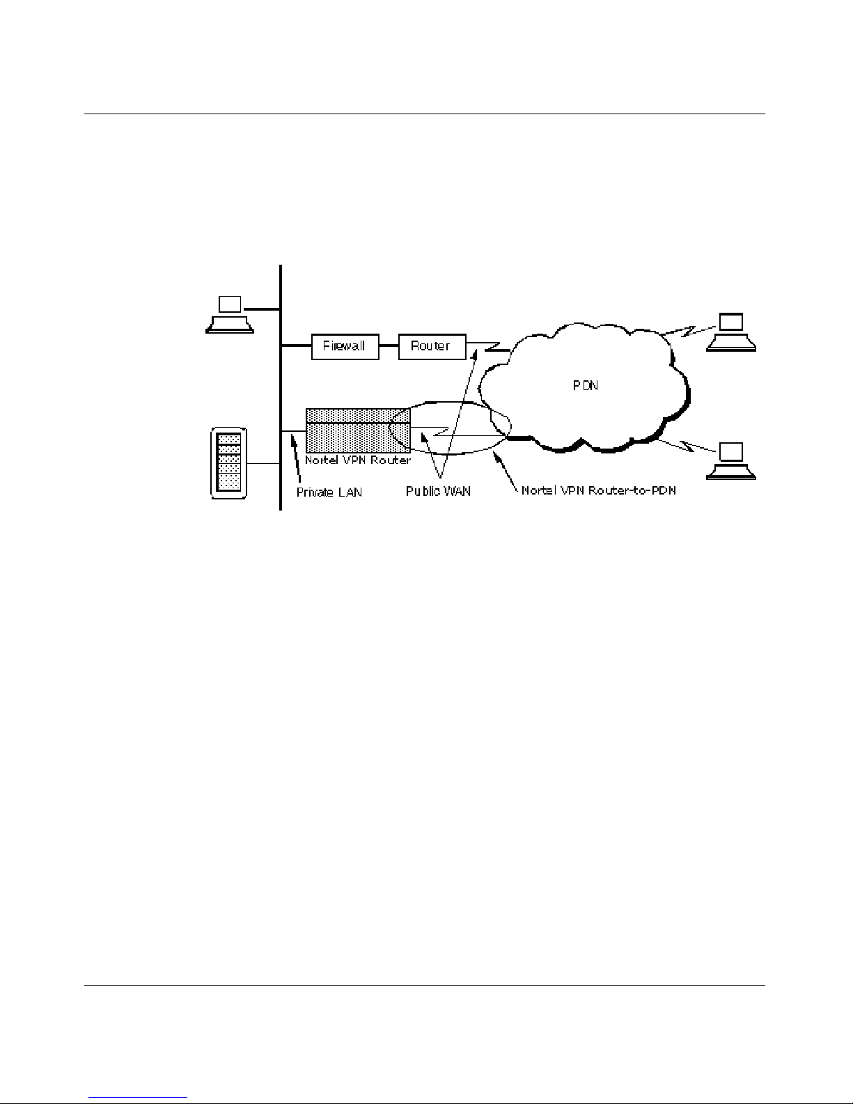
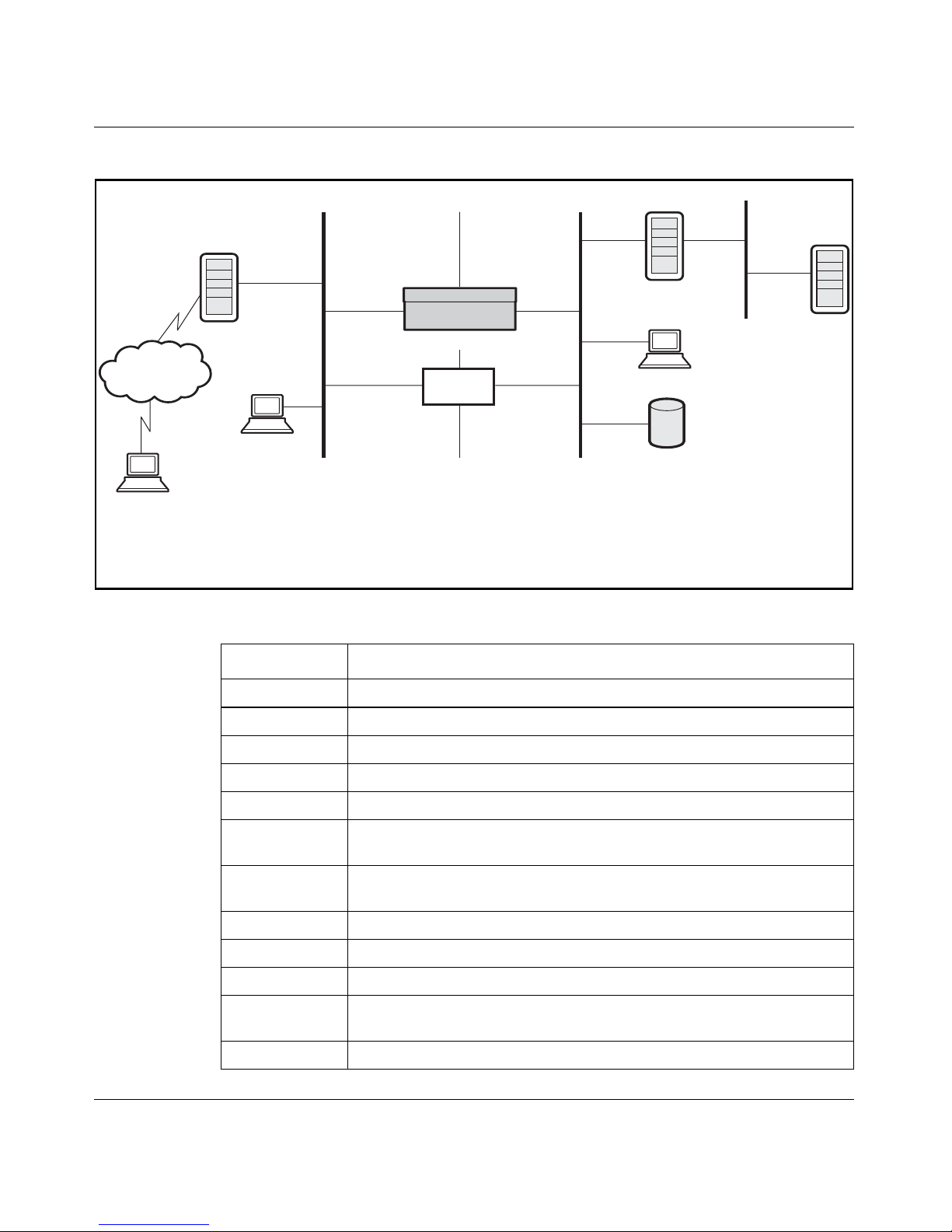
Nortel VPN Router access allows remote users to dial in to an Internet Service
Provider (ISP) anywhere and reach corporate headquarters or branch offices. The
Nortel VPN Router provides remote users access to corporate databases, mail
servers, and file servers. Figure 1 shows a typical packet data network (PDN).
Figure 1 Ty pi ca l P DN
The Nortel VPN Router allows ISPs to take over the role of point-of-presence
(POP) providers of modem access. It improves performance while lowering
overhead, which translates to significant corporate savings.
Virtual private networking
A VPN is a private data communication channel that uses a public IP network as
the basic transport for connecting corporate data centers, remote offices, mobile
employees, telecommuters, customers, suppliers, and business partners.
Physically discontiguous networks are made to appear logically connected and
contiguous.
A remote access VPN service requires the creation and operation of a secure
tunnel between client software on a remote device, such as a PC, and host
software on a Nortel VPN Router.
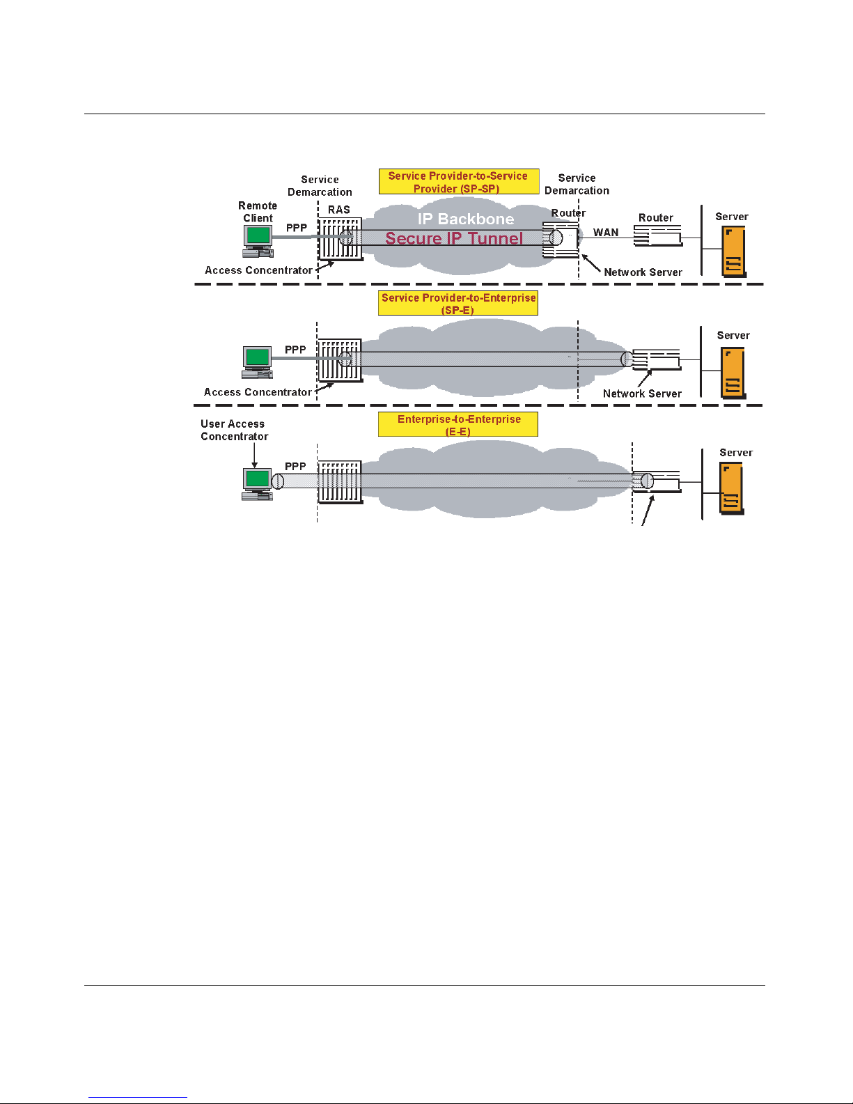
Figure 2 on page 27 shows examples of VPN services.
Page 27
Chapter 1 Overview 27
Nortel VPN Router Configuration — Basic Features
Figure 2 VPN service models
The Nortel VPN Router uses a combination of authorization, authentication,
privacy, and access control for each user.
Licensing features
Licence keys can be obtained through Nortel’s customer support. The Nortel VPN
Router provides several license key options:
• Advanced Routing
• Nortel VPN Router Stateful Firewall
• VPN Tunnels
•Premium
•DSLw
•BGP only
The Advanced Routing License key must be installed to enable OSPF on the
Nortel VPN Router. (The Firewall License Key is required only when the
redistribution capabilities of RIP and OSPF are necessary).
Page 28
28 Chapter 1 Overview
NN46110-500
The Nortel VPN Router Stateful Firewall License key must be installed to enable
the Nortel VPN Router Stateful firewall.
Tunnel keys are specific to the Nortel VPN Router hardware model that you are
using. Nortel VPN Router switches are manufactured to allow either access to the
maximum number of tunnels (VPN bundle) or support for 5 tunnels (Base Unit).
This feature offers reduced cost for users who want fewer tunnels. The existing
VPN bundle does not add a cost increase nor a need for a tunnel license key.
Command line interface
The command line interface allows you to make configuration changes to the
Nortel VPN Router via Telnet. You can access the command line interface by
initiating a Telnet session to the Nortel VPN Router management IP address. For
further information, see Nortel VPN Router Using the Command Line Interface .
Federal Information Processing Standard (FIPS)
You must separately order, purchase, and implement a FIPS kit to be FIPS
compliant. This kit contains detailed documentation concerning setting up,
operating, and configuring the Nortel VPN Router to be FIPS compliant. The
FIPS kit also includes tamper-resistant labels to be put on the hardware as
instructed in the FIPS kit documentation.
Note: It is only necessary to install a key once on each Nortel VPN
Router. To enter the license key, go to the Admin > Install screen. You
must reboot the Nortel VPN Router to gain access to the new tunnel
limit.
Page 29
29
Nortel VPN Router Configuration — Basic Features
Chapter 2
Getting started
This chapter describes methods for configuring and managing the Nortel VPN
Router .
Full details on hardware installation, including adding local area network (LAN)
or wide area network (WAN) cards, are in the Getting Started or installation guide
that came with the Nortel VPN Router. You should complete the hardware
installation before starting this chapter.
IP addressing
Figure 3 on page 30 shows sample IP address assignments in a network using a
Nortel VPN Router. Refer to Table 1 on page 30 to see the IP address associations.
Note: If you are setting up a Nortel VPN Router 1010, 1050 or 1100,
see Chapter 3, “Setting up the Nortel VPN Router 1010, 1050, and
1100.” These VPN Routers have unique set up and configuration
considerations.
Page 30
30 Chapter 2 Getting started
NN46110-500
Figure 3 Sample IP addressing scheme
Table 1 Sample IP addressing associations
IP address Description (when applicable, where configured)
192.168.43.6 Dial-up networking to ISP (Internet access, ISP assigned)
192.19.2.30 Public default Internet VPN Router
192.19.2.33 Public LAN port IP address (remote user destination address)
192.19.2.32 Firewall public network address
10.2.3.2 Nortel VPN Router management IP address: System > Identity
10.2.3.3 Nortel VPN Router private LAN interface IP address: System > LAN
Edit IP address
10.2.3.4 Private network default VPN Router: System > Routing Add/Edit
Default Route
10.2.3.6 Sample partners FTP server for inventory and price list
10.2.3.7 Firewall private network address
10.2.3.8 DHCP server IP address
10.2.1.1 to
10.2.1.254
Private Network Addresses Assigned to Remote Tunnel Sessions:
DHCP pool: Servers > User IP Addr
172.19.2.30 ISP-assigned address
And
Nortel VPN Router
Existing
Firewall
Existing Public Default
Gateway Router
Existing Private Default
Gateway Router
Public
Data Network
192.168.43.6
192.19.2.30
192.19.2.33
192.19.2.32
Web Server
Remote User
172.19.2.30
10.8.4.6
10.2.4.56
10.2.1.23
-or-
DHCP Server
10.2.1.1
-To-
10.2.1.254
192.19.2.31
10.2.3.7
10.2.3.8
Class C
Subnetworks
255.255.255.0
Class A
Subnetworks
255.0.0.0
10.2.3.6
10.2.3.4
10.10.0.5
10.10.0.1
10.2.3.3
10.2.3.2
Public Private
Page 31

Chapter 2 Getting started 31
Nortel VPN Router Configuration — Basic Features
The Nortel VPN Router supports the Internetwork Packet Exchange (IPX)
protocol. This allows the Nortel VPN Router to transmit and receive IPX packets
over PPTP.
The Nortel VPN Router supports IPX by encapsulating IPX traffic within IP
tunnels over PPTP. The private interfaces and public interfaces can carry IP and
IPX traffic simultaneously. The IPX addresses are not shown in the preceding
illustration.
Management virtual address
The management virtual address (MVA) is a reserved circuitless IP (CLIP)
address. The MVA is a unique CLIP address that is used only for management and
is separate from other CLIP addresses. Using a CLIP address ensures that there is
no dependency on any particular physical interface. This eliminates a single point
of failure. As long as there is a route through an interface to the MVA, you can
manage the Nortel VPN Router. Access to the MVA is supported on a public
interface through a VPN tunnel.
The following management protocols are available for MVA from the private side:
• HTTP
• HTTPS
•SNMP
•FTP
•Telnet
10.2.1.23 DHCP-assigned IP address for a remote user
10.8.4.6 Sample remote user static IP address: Profiles > Users Edit
10.2.4.56 Sample client-specified address: Profiles > Groups Edit IPsec/PPTP/
L2TP/L2F
Note: PPTP supports IPX traffic only for remote access connections.
IPX is not supported in branch office tunnels.
Table 1 Sample IP addressing associations (continued)
Page 32

32 Chapter 2 Getting started
NN46110-500
• Identification
• CRL Retrieval
•CMP
To enable or disable management protocols, go to Services > Available window.
From this window, you can also specify whether to manage the VPN Router from
the public or private side. To redistribute the MVA, go to Routing > Policy
window.
Figure 4 shows MVA with the CLIP address on a subnet that is separate from any
of the private physical interfaces.
Figure 4 MVA on separate subnet from private physical interfaces
Figure 5 on page 33 shows MVA with the CLIP address on the same subnet as one
of the private physical interfaces.
Page 33

Chapter 2 Getting started 33
Nortel VPN Router Configuration — Basic Features
Figure 5 MVA on same subnet as private physical interface
Figure 6 shows MVA using CLIP to manage from a remote PC tunneled from the
public side.
Figure 6 MVA managing from a remote PC
Page 34

34 Chapter 2 Getting started
NN46110-500
Configuring MVA with the serial menu
To configure the MVA with the serial menu:
1 Connect the serial cable (supplied with your Nortel VPN Router) from the
Nortel VPN Router serial port to a terminal or a communications port of a PC.
2 Power on the terminal or PC.
3 Using a terminal emulation program, such as HyperTerminal on the PC, press
Enter. Your terminal emulator must use the following communications
parameters:
• 9600 baud
• 8 data bits
• 1 stop bit
• No parity
• No flow control
The Welcome window appears and you are prompted to supply a user name
and password.
Welcome to the Nortel VPN Router
Copyright 1999,2000,2001 Nortel Networks
Version: V07_00.140
Creation date: Jan. 7, 2007, 20:51:06
Date: 04/27/2007
Unit Serial Number: 17563
4 Enter the administrator's user name, admin.
5 Enter the administrator's password,
setup.
Note: The factory default user name is admin and the default password
is setup.
Page 35

Chapter 2 Getting started 35
Nortel VPN Router Configuration — Basic Features
The following menu appears:
Main Menu: System is currently in NORMAL mode.
0) Management Address
1) Interfaces
2) Administrator
3) Default Private Route Menu
4) Default Public Route Menu
5) Create A User Control Tunnel (IPsec) Profile
6) Restricted Management ModeFALSE
7) Allow HTTP ManagementTRUE
8) Firewall Options
9) Shutdown
B) System Boot Options
P) Configure Serial Port
C) Controlled Crash
L) Command Line Interface
R) Reset System to Factory Defaults
E) Exit, Save and Invoke Changes
Please select a menu choice (0 - 9,B,P,C,L,R,E):
6 Typ e 0 and press Enter to display the Management IP Address menu.
Please select a menu choice (0 - 9,B,P,C,L,R,E): 0
- Management IP Address menu
M) Management IP Address = 192.168.249.44
R) Return to the Main Menu
Please select a menu choice (M,R):
Note: This administrator’s password is also the primary administrator’s
password. This password guarantees access to the Nortel VPN Router
through the serial port or a Web browser. This administrator’s user ID
(default = admin) and password (default = setup) combination is also
called the primary administrator. This person always has access to all
windows and controls, including the serial port and the recovery disk.
Only one primary administrator is allowed.
Page 36

36 Chapter 2 Getting started
NN46110-500
7 Typ e M and press Enter to change the Management IP address. The current
IP address appears. The Old Management IP Address field is blank on a new
Nortel VPN Router.
Please select a menu choice (M, R): M
Type 0.0.0.0 to delete.
Just type <CR> to skip.
Old Management IP Address = 192.168.249.44
New Management IP Address =
Configuring Interfaces
Use the following procedure to configure the interfaces of the system.
1 Typ e 1 and press Enter to display the configured Interfaces:
Please select a menu choice (0 - 9,B,P,C,L,R,E): 1
- Interface Menu
0) Slot 0, Port 1, Private LAN
IP Address = 47.17.163.163
Subnet Mask = 255.255.255.240
Speed/Duplex = AutoNegotiate
1) Slot 1, Port 1, Public LAN
IP Address =
Subnet Mask = 0.0.0.0
Speed/Duplex = AutoNegotiate
2) Slot 2, Port 1, Public LAN
IP Address =
Subnet Mask = 0.0.0.0
Speed/Duplex = AutoNegotiate
3) Slot 4, Port 1, Public WAN
IP Address =
Subnet Mask = 255.255.255.255
Line Format = T1
Line Coding = B8ZS
HDLC Polarity = normal
Line Framing = T1 ESF
Line Build Out = 0.0 dB
Timing Source = Loop
Performance Report Message = ANSI
Page 37

Chapter 2 Getting started 37
Nortel VPN Router Configuration — Basic Features
Utilized Channels (Fractional T1)
1 2
12345678902345678901234
Currently=
R) Return to the Main Menu.
Please select a menu choice:
2 Select 0 and press Enter to enter the Slot 0, Port 1, Private LAN menu and
add the interface IP address.
Please select a menu choice: 0
0) Slot 0, Port 1, Private LAN
IP Address = 47.17.163.163
Subnet Mask = 255.255.255.240
Speed/Duplex = AutoNegotiate
* Type 0.0.0.0 to delete.
* Just type <CR> to skip.
Old IP Address = 47.17.163.163
New IP Address =
3 Enter a new IP address for the interface or press Enter to leave the current
value. The subnet mask menu appears.
Old Subnet Mask = 255.255.255.240
New Subnet Mask =
4 Enter the desired subnet mask and press Enter. The Interface option menu
appears. Select the desired option and press Enter.
No change to IP Address
Old Speed/Duplex = AutoNegotiate
1) AutoNegotiate (Default)
2) 100<Mbs-FullDuplex
3) 100Mbs-HalfDuplex
4) 10Mbs-FullDuplex
5) 10Mbs-HalfDuplex
<CR> Leave unchanged
Please select a menu choice (1-5, <CR>):
5 After you complete the configuration, press Enter to return to the Interface
menu.
6 Typ e R and press Enter to return to the main menu.
Page 38

38 Chapter 2 Getting started
NN46110-500
7 Typ e E and press Enter to save the settings and exit. You can then manage the
Nortel VPN Router from a Web browser.
Multinetting
IP multinetting allows a maximum of eight addresses to be configured on a single
Ethernet interface. The first IP address configured on the interface is the primary
address. Subsequent IP addresses are secondary addresses, or subnets. All the
subnets on a physical interface share the security rules configured for the primary
subnet. You can configure only one set of Interface Filter rules per physical
interface.
Multinetting is commonly used in IP networks as part of a transition strategy. As
networks evolve, consolidation of several physical networks is often necessary. To
avoid re-addressing, the physical networks are consolidated onto a multinetted
Nortel VPN Router interface. Multinetting allows hosts to migrate to the new IP
interface or maintain the previous IP address. You can add Multinet IP addresses
to the private side or the public side of the VPN Router .
Statistics and logging are done at the interface level and in most cases are not
available separately for each secondary address on the interface.
Overall throughput using multinetting, instead of a non-multinetting application,
has no significant degradation. There is also no degradation of forwarding
performance.
Note: It is very important that broadcast packets originated by the router
not use the local subnet broadcast. Whenever multiple Routing
Information Protocol (RIP) interfaces are created on the same physical
interface of a router, all of those interfaces MUST be configured with an
explicit broadcast address of 255.255.255.255 in order to avoid routing
loops.
Page 39

Chapter 2 Getting started 39
Nortel VPN Router Configuration — Basic Features
Table 2 shows the services supported on a multinetted interface.
Table 2 Services supported on a multinetted interface
Service Integration description
Nortel VPN Router
Stateful Firewall
Supported at the interface level specified under the
Primary address on the interface. The same rules apply
to all other secondary addresses on the interface.
Interface Packet Filters
Filtering capability supported at the interface level
specified under the Primary address on the interface.
The same rules apply to all other secondary addresses
on the interface.
FW User Auth
(FWUA)
Access/Authentication capability of FWUA supported
at the interface level specified under the primary
address on the interface. The same rules apply to all
other secondary addresses.
NAT Support for NAT on multinetted addresses, with a single
set of rules for all interfaces in Nortel VPN Router. NAT
services available discretely for each subnet on a multinetted interface (separately supported on each
subnet address).
Diff Serv Call admission/priority, forwarding priority, BWM -
rate limiting (tunnel traffic) and Diffserv provided at the
interface level specified under the Primary address on
the interface. The same rules apply to all other secondary addresses on the interface.
Multinetting with
VLAN tagging
Support for multinetting a tagged interface. Example:
Interface 1/1
Sub-interface 10
encaps dot1q 10
ip address 10.1.1.1 255.255.255.0
ip address 10.2.2.2 255.255.255.0
Tunneling Support for Tunnel termination and origination sepa-
rately on each/all multinet address/es.
Page 40

40 Chapter 2 Getting started
NN46110-500
Multinetting is supported on the following Nortel VPN Routers: Nortel VPN
Router 1100/1010/1050 and 600, 1700, 1600/1500, 2700, 2600/2500, 4500/4600
and 5000. The multinetting feature is interoperable with Nortel VPN Router
100-400, BayRS, P8000 (8100, 8600, 1200) and Baystack LAN/Campus
switches, and Cisco IOS routers.
Figure 7 on page 41 represents a legacy system consisting of two class B IP
subnets, 10.1.0.0/16 and 11.1.0.0/16. Both subnets are connected to one physical
LAN port on Nortel VPN Router. Nortel VPN Router sends packets to and
receives packets from a host on either of these networks using the same physical
port.
Authentication Protocols (RADIUS)
Support for interface authentication at the interface
level, as specified under the Primary address on the
interface. The same rules apply to all other secondary
addresses on the interface.
VRRP Supported when Primary address is used as the VRRP
master/backup address. VRRP not applicable on secondary addresses.
Other routing (RIP,
OSPF, Static)
Routing protocols are configured separately on each
address (subnet) on a multinetted interface.
DHCP server Internal DHCP Server assumes address requests are for
the subnet of the primary interface. DHCP Relay function from a multinetted interface forwards the interface
address as the primary address in relaying a DHCP
request.
Management Protocols (HTTP; HTTPS;
SNMP; FTP; Telnet;
Identification; CRL
Retrieval; CMP)
Primary address on the interface is the management
address for the Nortel VPN Router Device. Secondary
addresses cannot be the management address.
Table 2 Services supported on a multinetted interface
Service Integration description
Page 41

Chapter 2 Getting started 41
Nortel VPN Router Configuration — Basic Features
Figure 7 Deployment Scenario
Changing the management IP address
To manage the system, the network must have a route to the management IP
address through one of the system interfaces.
To change the management IP address, complete the following procedure:
1 Connect the serial cable (supplied with your Nortel VPN Router) from the
Nortel VPN Router serial port to a terminal or a communications port of a PC.
2 Power on the terminal or PC.
3 Using a terminal emulation program, such as HyperTerminal on the PC,
access the Nortel VPN Router. Your terminal emulator must use the following
communications parameters:
• 9600 baud
• 8 data bits
Page 42

42 Chapter 2 Getting started
NN46110-500
• 1 stop bit
• No parity
• No flow control
The Welcome window appears and you are prompted to supply a user name
and password.
Nortel VPN Router
Copyright (c) 1999-2007 Nortel Networks, Inc.
Version: V07_00.038
Creation date: Oct 11 2006, 09:52:35
Date: 10/13/2006
Unit Serial Number: 10167
Released Software, Fully supported
4 Enter the administrator's user name, admin.
5 Enter the administrator's password,
setup.
Note: The factory default user name is admin and the default password
is setup.
Note: This administrator’s password is also the primary administrator’s
password. This password guarantees access to the Nortel VPN Router
through the serial port or a Web browser. This administrator’s user ID
(default = admin) and password (default = setup) combination is also
called the primary administrator. This person always has access to all
windows and controls, including the serial port and the recovery disk.
Only one primary administrator is allowed.
Page 43

Chapter 2 Getting started 43
Nortel VPN Router Configuration — Basic Features
The following menu appears:
Main Menu: System is currently in NORMAL mode.
0) Management Address
1) Interfaces
2) Administrator
3) Default Private Route Menu
4) Default Public Route Menu
5) Create A User Control Tunnel (IPsec) Profile
6) Restricted Management ModeFALSE
7) Allow HTTP ManagementTRUE
8) Firewall Options
9) Shutdown
B) System Boot Options
P) Configure Serial Port
C) Controlled Crash
L) Command Line Interface
R) Reset System to Factory Defaults
E) Exit, Save and Invoke Changes
Please select a menu choice (0 - 9,B,P,C,L,R,E):
6 Typ e 0 and press Enter to display the Management IP Address menu.
Please select a menu choice (0 - 9,B,P,C,L,R,E): 0
- Management IP Address menu
M) Management IP Address = 192.168.249.44
R) Return to the Main Menu
Please select a menu choice (M,R):
7 Typ e M and press Enter to change the Management IP address. The current
IP address appears. The Old Management IP Address field is blank on a new
Nortel VPN Router.
Please select a menu choice (M, R): M
Type 0.0.0.0 to delete.
Just type <CR> to skip.
Old Management IP Address = 192.168.249.44
New Management IP Address =
Page 44

44 Chapter 2 Getting started
NN46110-500
Restricting source IPs access to management
You are able to filter management access of source IP addresses. Access Lists
(ACLs) restrict connection of designated source IPs for management purposes
over HTTP, FTP, TELNET and SNMP. Management traffic is intercepted and if
the destination is System and the packet is for one of the four services above, the
source IP address is matched against the ACL that is set for the particular service.
If no ACL is defined for HTTP, for example, then http traffic is permited for any
IP address that comes as a source address in the packet.
The IP address of a source client is logged in the syslog output whether the logon
connection attempt is successful or not.
Configuring ACL through the CLI:
Use the following commands to configure ACL in CLI:
To set an ACL for HTTP, enter the following NNCLI command:
CES(config)#http access-list <the_name_of_an_acl>
To remove an ACL for HTTP, enter the following command:
CES(config)#no http access-list
To set an ACL for FTP, enter the following NNCLI command:
CES(config)#ftp-server access-list <the_name_of_an_acl>
To remove an ACL for FTP, enter the following command:
CES(config)#no ftp-server access-list
To set an ACL for SNMP, enter the following NNCLI command:
CES(config)#snmp-server access-list <the_name_of_an_acl>
To remove an ACL for SNMP, enter the following command:
CES(config)#no snmp-server access-list
Page 45

Chapter 2 Getting started 45
Nortel VPN Router Configuration — Basic Features
To set an ACL for TELNET, enter the following NNCLI command:
CES(config)#telnet access-list <the_name_of_an_acl>
To remove an ACL for TELNET, enter the following command:
CES(config)#no telnet access-list
Accessing ACL through the GUI:
To access ACLs from the GUI:
1 Select Services > Available. The Allowed Services window appears.
2 Select one of the predefined ACLs.
3 Click OK.
Configuring the serial interface
The Serial Interface allows you to configure the IP address and subnet mask so
that you can then use a Web browser for management.
Your terminal emulator must use the following communications parameters:
• 9600 baud
• 8 data bits
• 1 stop bit
• No parity
• No flow control
The Serial Interface configuration procedure is typically only necessary in a
system recovery situation.
1 Connect the serial cable (supplied with your Nortel VPN Router) from the
Nortel VPN Router serial port to a terminal or a communications port of a PC.
2 Power on the terminal or PC.
Page 46

46 Chapter 2 Getting started
NN46110-500
3 Using a terminal emulation program, such as HyperTerminal on the PC, press
Enter. The Welcome window appears and you are prompted to supply a user
name and password.
Nortel VPN Router
Copyright (c) 1999-2007 Nortel Networks, Inc.
Version: V07_00.038
Creation date: Oct 11 2006, 09:52:35
Date: 10/13/2006
Unit Serial Number: 10167
Released Software, Fully supported
4 Please enter the administrator's user name: admin
Page 47

Chapter 2 Getting started 47
Nortel VPN Router Configuration — Basic Features
5 Please enter the administrator's password: setup
6 After the user name and password have been entered, the following menu
appears:
The following menu appears:
Main Menu: System is currently in NORMAL mode.
0) Management Address
1) Interfaces
2) Administrator
3) Default Private Route Menu
4) Default Public Route Menu
5) Create A User Control Tunnel (IPsec) Profile
6) Restricted Management ModeFALSE
7) Allow HTTP ManagementTRUE
8) Firewall Options
9) Shutdown
B) System Boot Options
P) Configure Serial Port
C) Controlled Crash
L) Command Line Interface
R) Reset System to Factory Defaults
E) Exit, Save and Invoke Changes
Please select a menu choice (0 - 9,B,P,C,L,R,E):
7 Typ e 1 and press Enter to display the configured Interfaces:
Please select a menu choice (0 - 9,B,P,C,L,R,E): 1
Note: The factory default user name is admin and the default password
is setup.
Note: This administrator’s password is also the primary administrator’s
password. This password guarantees access to the Nortel VPN Router
through the serial port or a Web browser. This administrator’s user ID
(default = admin) and password (default = setup) combination is also
called the primary administrator. This person always has access to all
windows and controls, including the serial port and the recovery disk.
Only one primary administrator is allowed.
Page 48

48 Chapter 2 Getting started
NN46110-500
- Interface Menu
0) Slot 0, Port 1, Private LAN
IP Address = 47.17.163.163
Subnet Mask = 255.255.255.240
Speed/Duplex = AutoNegotiate
1) Slot 1, Port 1, Public LAN
IP Address =
Subnet Mask = 0.0.0.0
Speed/Duplex = AutoNegotiate
2) Slot 2, Port 1, Public LAN
IP Address =
Subnet Mask = 0.0.0.0
Speed/Duplex = AutoNegotiate
3) Slot 4, Port 1, Public WAN
IP Address =
Subnet Mask = 255.255.255.255
Line Format = T1
Line Coding = B8ZS
HDLC Polarity = normal
Line Framing = T1 ESF
Line Build Out = 0.0 dB
Timing Source = Loop
Performance Report Message = ANSI
Utilized Channels (Fractional T1)
1 2
12345678902345678901234
Currently=
R) Return to the Main Menu.
Please select a menu choice:
Page 49

Chapter 2 Getting started 49
Nortel VPN Router Configuration — Basic Features
8 Select 0 and press Enter to enter the Slot 0, Port 1, Private LAN menu and
add the interface IP address.
Please select a menu choice: 0
0) Slot 0, Port 1, Private LAN
IP Address = 47.17.163.163
Subnet Mask = 255.255.255.240
Speed/Duplex = AutoNegotiate
* Type 0.0.0.0 to delete.
* Just type <CR> to skip.
Old IP Address = 47.17.163.163
New IP Address =
9 Enter a new IP address for the interface or press Enter to leave the current
value. The subnet mask menu appears.
Old Subnet Mask = 255.255.255.240
New Subnet Mask =
10 Enter the desired subnet mask and press Enter. The Interface option menu
appears. Select the desired option and press Enter.
No change to IP Address
Old Speed/Duplex = AutoNegotiate
1) AutoNegotiate (Default)
2) 100<Mbs-FullDuplex
3) 100Mbs-HalfDuplex
4) 10Mbs-FullDuplex
5) 10Mbs-HalfDuplex
<CR> Leave unchanged
Please select a menu choice (1-5, <CR>):
11 After you complete the configuration, press Enter to return to the Interface
menu.
12 Type R and press Enter to return to the main menu.
13 Type E and press Enter to save the settings and exit. You can then manage the
Nortel VPN Router from a Web browser.
Page 50

50 Chapter 2 Getting started
NN46110-500
Using boot modes
The Nortel VPN Router can be booted in one of two system modes: Safe mode or
Normal mode. Each mode has its own software image, configuration files, and
LDAP database.
A system booted in Safe mode is only allowed to accept secured management
tunnel establishment. When the secured management tunnel is established, Telnet,
HTTP, and FTP traffic is allowed to come into the Nortel VPN Router; no other
VPN traffic is allowed through the secured management tunnel of the Nortel VPN
Router.
In Normal mode, the system operates with the normal software and configuration
and transports both VPN traffic and management traffic.
To save your configuration into the Safe Mode boot directory:
1 Select B) System Boot options.
2 Select 2) System Reset options.
3 Select 1) Reset system to Normal Mode.
4 Select 2) Reset system to Safe Mode.
Managing through a Web browser
After you use the serial interface configuration, launch a Web browser of your
choice.
1 Enter the management IP address to invoke the Nortel Login window. For
example, if the management IP address is 10.2.3.2, then the Uniform
Resource Locator (URL) is http://10.2.3.2.
2 Select an option in the navigation menu and submenu, and then you are
prompted for the login and password.
Note: The Nortel VPN Router 1010, 1050, and 1100 do not implement
safe mode.
Page 51

Chapter 2 Getting started 51
Nortel VPN Router Configuration — Basic Features
3 Enter the system default login and password in lowercase characters, as
follows:
Login:
admin
Password: setup
At this point, follow the Quick Start Configuration procedure or the Guided
Configuration procedure. Refer to Table 3 on page 53 for help in determining
which procedure to use.
Page 52

52 Chapter 2 Getting started
NN46110-500
Preparing for configuration
To properly prepare for configuration of the Nortel VPN Router, you should have
the following items available:
• A plan to distribute IP addresses to clients when connections are requested;
for example, via a DHCP server or an internal client address pool (with an
address pool you need a range of IP addresses).
• An Authentication database. If you are not using internal authentication via
the LDAP database, then make sure you have either the external LDAP or the
RADIUS server’s IP address and password or Shared Secret (password).
• An external accounting server, such as RADIUS, with its IP address and
Shared Secret (password).
• Prepare the clients for the type of tunneling protocol they need to use. The
PPTP client application is available on the Nortel CD for Windows 95, and it
comes with Windows 98 and Windows NT. Nortel also provides the IPsec
client on the Nortel CD.
You should develop a complete network topology (physical and logical) of the
environment in which you are testing the Nortel VPN Router. This should include
the following:
• Details of physical communication links, such as cable length, grade, and
approximation of the physical paths of the wiring, analog, fiber and ISDN
lines.
• Nortel VPN Router and router types.
• Servers, with computer name, IP address (if static), server role, and domain
membership.
• Location of devices such as printers, hubs, Nortel VPN Routers, modems,
routers, bridges, proxy servers and firewalls (intranet & Internet) on the
network.
• WAN communication links (analog / ISDN / ATM) and the available
bandwidth between sites, either an approximation or the actual measured
capacity.
• Number of users at each site, including mobile users.
Page 53

Chapter 2 Getting started 53
Nortel VPN Router Configuration — Basic Features
• Manufacturer of device as well as firmware version, throughput, and any
special configuration requirements for any devices on the network. If you
assign static IP addresses to any of these devices, record them and a brief
explanation why they required static addresses.
• Include brief explanations with the layout.
• Domain architecture, including the existing domain hierarchy, names, and
addressing scheme.
• Trust relationships, including representations of transitive, one-way, and
two-way trust relationships.
• Mixed environments (HP-UX, AIX, Linux, Solaris, Windows NT/ 2000,
Macintosh).
• All protocols that exist within the network.
Tabl e 3 shows the alternatives when first configuring your Nortel VPN Router.
Begin with either the Quick Start or the Guided Configuration. After you are
familiar with the Nortel VPN Router navigational menu and capabilities, select
Manage Switch.
Tabl e 4 provides a place for you to record the information that you need to
configure basic Nortel VPN Router parameters.
Table 3 Web interface configuration options
Configuration type Results
Quick Start Configure and test a basic PPTP configuration
Guided Config Structured Nortel VPN Router configuration and
management
Manage Switch Comprehensive Nortel VPN Router configuration and
management
Table 4 Configuration checklist
window Values required Your Values
System > Identity Management IP address
System > Identity Host name
Domain name
Page 54

54 Chapter 2 Getting started
NN46110-500
System > Identity Primary IP address
Secondary IP address
Tertiary IP address
System
> LAN Private IP address
Public IP address
System
> WAN (if using
T1, V.35, or T3)
ISP provided information
System
> Date and Time Manual entry of date and time or
NTP configuration server
broadcast or multicast IP address
Services > Available
Tunnel Type
IPsec private address
IPsec public address
PPTP private address
PPTP public address
L2TP and L2F public address
L2TP and L2F private address
Services
> Available
Management Protocol
HTTP private address
HTTP public address
SNMP private address
SNMP public address
FTP private address
FTP public address
TELNET private address
TELNET public address
CRL retrieval private address
CRL retrieval public address
Routing
> Static Routes
Enabled/Disabled
Public Nortel VPN Router IP
address
Private Nortel VPN Router IP
address
Routing > OSPF
Enabled/Disabled
Router ID
AS boundary router (true or false)
Routing
> Rip
Enabled/Disabled
True or false
Routing
> Interfaces
LAN IP Address
OSPF (enabled or disabled)
RIP (enabled or disabled)
VRRP (enabled or disabled)
Table 4 Configuration checklist (continued)
window Values required Your Values
Page 55

Chapter 2 Getting started 55
Nortel VPN Router Configuration — Basic Features
Servers > Radius Auth Access (enabled or disabled
Server-Supported Option (enabled
or disabled)
Radius Servers (enabled or
disabled)
Primary host name or IP
addresses, public or private, Port,
Shared secret/confirmed
Alternate 1 host name or IP
addresses, public or private, Port,
Shared secret/confirmed
Alternate 2 host name or IP
addresses, public or private, Port,
Shared secret/confirmed
Servers
> LDAP Internal or external
Base DN
Master IP address, port or SSL
Bind DN, Bind password,
Confirmed
Slave 1 IP address, port or SSL
Bind DN, Bind password,
Confirmed
Slave 2 IP address, port or SSL
Bind DN, Bind password,
Confirmed
Servers
> User IP Addr Broadcast Any DHCP or
DHCP servers:
Primary IP address
Secondary IP address
Tertiary IP address
Address pool:
Pool name
Start
End
Subnet mask
Table 4 Configuration checklist (continued)
window Values required Your Values
Page 56

56 Chapter 2 Getting started
NN46110-500
Welcome window
The Welcome window allows access to any of the configuration areas for the
Nortel VPN Router.
Before entering the configuration options, first register your Nortel VPN Router to
activate licenses, warranties, and services.
To start using your Nortel VPN Router, choose from one of the following options:
• Click on Manage Switch to begin a configuration management session. This
option allows access to all Configuration Management facilities. For your first
configuration, follow the Quick Start or Guided Configuration.
• Click on Manage from Notebook to run the Nortel VPN Router Manager in
notebook display mode.
• Click on Quick Start to begin the Quick Start Configuration. This option
allows you to configure interfaces, set up PPTP tunnels for up to three users,
and establish a connection to the Nortel VPN Router. If you prepare for the
configuration as recommended, the Quick Start can take as little as 15 minutes
to complete.
Admin > License Keys
Install License Keys
Advanced routing install key
Nortel VPN Router Stateful
Firewall install key
Admin
> Auto Backup Automatic Backup file servers
IP address of FTP servers for
backup:
Host
Path
User ID
Password
Table 4 Configuration checklist (continued)
window Values required Your Values
Page 57

Chapter 2 Getting started 57
Nortel VPN Router Configuration — Basic Features
• Click on Guided Config to begin the Guided Configuration. This option
allows access to all Configuration Management facilities. The design and
structure of the Guided Configuration, however, is such that you might want
to follow the top-to-bottom layout provided. This approach walks you through
the entire navigational menu from the Profiles to the Admin selections.
Each functional area begins with a summary of the objectives of the area and
then steps you through the area (for example, profiles), one subsection at a
time. Context-sensitive help is available at each subsection to supplement the
summary.
Provided you have the information required to set up the Nortel VPN Router,
the Guided Configuration is estimated to take two to three hours to complete,
depending on how extensive your configuration is.
The Nortel VPN Router navigational menu options include the top-level
configuration and monitoring areas of the Nortel VPN Router. Each of these key
areas has secondary levels, which appear once you click on an area; for example,
when you click on System, the secondary level listings appear. The menu is
structured to provide system configuration details, followed by profiles for groups
and users. Then you can configure authentication servers, secure tunnels,
administrative details, and monitor the status of the Nortel VPN Router.
Page 58

58 Chapter 2 Getting started
NN46110-500
Page 59

59
Nortel VPN Router Configuration — Basic Features
Chapter 3
Setting up the Nortel VPN Router 1010, 1050, and 1100
This chapter provides instructions for the network administrator who is
responsible for the Nortel VPN Router 1010, 1050, and 1100 located at branch
office sites. If you are at a branch office site and you need to connect the Nortel
VPN Router 1010, 1050, or 1100 to the network, see “Connecting for Internet
access” on page 67. (This information was also included with the VPN Router.)
Unless you are the network administrator, you need not read the rest of this
chapter
The Nortel VPN Router 1010, 1050, and 1100 series of switches provides support
for five (5) tunnels at introduction and 30 tunnels for licensing. The maximum
tunnels include the sum of all branch office, client, and management tunnels
combined. For example, if one management tunnel and two branch office tunnels
are open, only two client tunnels can be connected initially (27 client tunnels with
the 30 tunnel license). The license is for 25 additional tunnels. LDAP supports
150 entries.
Default configuration
The 1010, 1050, 1100 default configuration is set up to meet requirements for the
majority of small office connections. This configuration includes a public
interface configured for IP and can receive an address via DHCP from the ISP.
The private side has the DHCP server enabled and the DHCP address pool set to
192.168.1.3–192.168.1.254.
Figure 8 on page 60 show a typical default configuration.window
Page 60

60 Chapter 3 Setting up the Nortel VPN Router 1010, 1050, and 1100
NN46110-500
Figure 8 Default configuration
By default, the Nortel VPN Router 1010, 1050, and 1100 are configured with the
following parameters:
• The DHCP server is configured on the switch’s private interface, with a
default range of 192.168.1.3/24 to 192.168.1.255/24. By default, 192.168.1.1
and 192.168.1.2 are assigned to the branch office switch’s private and
management interfaces, respectively. The DHCP server provides its own
address for the DNS server and default Nortel VPN Router.
• The DHCP client is configured on the switch’s public interface to retrieve its
IP address from the ISP’s DHCP server. Other parameters retrieved from the
DHCP server should include the default Nortel VPN Router and the DNS
server.
• DNS proxy is configured to forward DNS requests to an external DNS server.
The address of the DNS server is obtained during startup from the ISP’s
DHCP.
• Network Address Translation (NAT) translates the private IP address space
(determined by default configuration of the DHCP server) into one public
address assigned to the public interface by your ISP.
• Port NAT maps multiple IP addresses in the private space to a single public IP
address. The default configuration only supports initiating IP sessions from
the private side of the switch, which reduces security risks.
• The Nortel VPN Router Interface Filter is set as the default firewall.
• The firewall setting PermitAll is the default for both the public and private
interfaces. This default is different from the DenyAll default setting for other
Nortel VPN Routers.
Page 61

Chapter 3 Setting up the Nortel VPN Router 1010, 1050, and 1100 61
Nortel VPN Router Configuration — Basic Features
Branch office quick start utility
The branch office quick start utility (BOQS) simplifies deployment of the Nortel
VPN Router in the branch office environment. BOQS converts the Nortel VPN
Router 1010, 1050, or 1100 device from an Internet access VPN Router into a
secure access VPN Router by provisioning a VPN connection to a central office or
optionally, to a network operation center (NOC). BOQS allows a NOC or central
office management to access the Nortel VPN Router 1010, 1050, or 1100 so that
network administrators can further configure the these units without going to the
remote site.
Network administrators and service providers can use the branch office quick start
for provisioning IP-based VPN services on a large scale. It provides VPN services
using Nortel VPN Router 1010, 1050, or 1100 devices as branch office VPN
switches and other Nortel VPN Routers as central office switches.
In addition to connectivity, the central office switch must be able to accept newly
created secure connections from the Nortel VPN Router 1010, 1050, or 1100.
Therefore, the BOQS must be used with the knowledge and approval of a network
administrator. It can only be initiated after IP addressing has been planned and the
central office switch has been configured. Then you can send the provisioning
parameters to the remote branch office locations.
The Nortel VPN Router 1010, 1050, and 1100 must be connected to a public
network and have access to the Internet before local users can use BOQS. The
unique default configuration allows easy deployment of Nortel VPN Router 1010,
1050, and 1100 switches in DHCP configurations (where a DHCP server is used
on the public network). However, if you use static IP addressing or PPPoE on the
public side, the Nortel VPN Router 1010, 1050, or 1100 must be configured
manually before local users can use BOQS.
All users on the private network must renew their IP addresses. For further
information, see your Microsoft documentation. When the branch office tunnels
are established, public access to the Internet is replaced with access to the central
office.
Note: The BOQS will remain accessible after the information is entered.
The network administrator must change the admin account (username/
password) to restrict access.
Page 62

62 Chapter 3 Setting up the Nortel VPN Router 1010, 1050, and 1100
NN46110-500
After the VPN services are provisioned, branch office networks are logically
connected to a central office network or to a NOC network. Branch office end
users can rerun BOQS multiple times to restore the initial VPN configuration or to
fix data errors.
BOQS supports two network topologies:
• Enterprise topology where the network operations center is located within the
central office.
• Service Provider topology where the network operations center is an
independent entity from the central office
Enterprise environment
Before you deploy the Nortel VPN Router 1010, 1050, or 1100 switches at the
local sites, you must configure routing and tunnels on the switch at the central
office.
For routing, you must do the following:
• Enable global RIP service.
• Enable RIP on private interface.
• Disallow importing default routes in the group where responder tunnels are
created.
For tunnels, you must do the following:
• Create one responder tunnel for each branch office Nortel VPN Router 1010/
1050/1100 device.
• Set the Connection Type to Responder.
• Be sure that the Control Tunnel option is NOT selected.
• Determine the connection name for the tunnel. Nortel recommends that the
name be the same as the initiator ID, but it could be the same as the central
office tunnel name.
• Set the state to Enabled.
• Set the Local Filter to permit all.
• Set IPSEC Authentication to Text Pre-Shared Key.
• Set the Initiator ID to the same name as the central office tunnel name.
Page 63

Chapter 3 Setting up the Nortel VPN Router 1010, 1050, and 1100 63
Nortel VPN Router Configuration — Basic Features
• Set the Text Pre-Shared Key to the same name as central office tunnel
password.
• Set Dynamic Routing to enabled.
• Set RIP to enabled.
After the central office setup and the BOQS are complete, the Nortel VPN
Router1010, 1050, or 1100 is directly accessible from the central office. This
means that there is just one hop between the central office and the branch office.
RIP propagates routes to this subnet across the tunnel created by BOQS.
You must have at least two more IP addresses than IP workstations on the Nortel
VPN Router 1010, 1050, or 1100 private network. The first address from the
subnet is assigned to the private interface of the branch office switch and the
second address becomes the management IP address of the switch. Each branch
office must be in its own subnet.
Tabl e 5 shows how offices with approximately 50 workstations can each have
subnets assigned.
Service provider environment
Service providers generally have an isolated NOC from which all devices are
managed. The addressing scheme could be different from a central office and
require a separate designated tunnel to configure the Nortel VPN Router 1010/
1050/1100 series of switches.
Table 5 Subnet assignments
Private
Network IP
address
Private Network
IP Mask
Nortel VPN
Router1010/1050/
1100 Private
Interface Address
Nortel VPN
Router1010/1050/
1100 Management
Interface Address
BO Workstations
Addresses (assigned
by DHCP Server)
200.1.1.0 255.255.255.192 200.1.1.1 200.1.1.2 From 200.1.1.3 to
200.1.1.62
200.1.1.64 255.255.255.192 200.1.1.65 200.1.1.66 From 200.1.1.67 to
200.1.1.126
200.1.1.128 255.255.255.192 200.1.1.129 200.1.1.130 From 200.1.1.131 to
200.1.1.190
Page 64

64 Chapter 3 Setting up the Nortel VPN Router 1010, 1050, and 1100
NN46110-500
Every Nortel VPN Router 1010, 1050, and 1100 must have a distinct IP address
that is visible from the NOC subnet. A NOC can assign any address reachable
from a NOC network to a Nortel VPN Router 1010, 1050, or 1100. BOQS
configures NAT on the NOC tunnel to translate the address specified in the
“Branch office switch manage NAT IP address” and “management address from
branch office private subnet.” If the field is empty, the NOC must use an actual
management address to access the Nortel VPN Router 1010, 1050, or 1100.
Because the NOC tunnel uses static routing, all Nortel VPN Router 1010, 1050,
and 1100 devices must be configured with a static route to the NOC private
network. The NOC private address and NOC private mask fields are where a
BOQS user enters this information. This information is the same for all Nortel
VPN Router 1010, 1050, and 1100 devices.
You must provision the NOC switch to accept control tunnel connections from the
branch office. Because static routing is used in control tunnels, you do not have to
enable routing protocols on the NOC switch. Use the following guidelines:
• All responder tunnels should be created in one group or in subgroups of one
group for easy management. Connection Name of the tunnel should
correspond to NOC tunnel name and created in an enabled state with local
filter set to Permit All.
• Text Pre-Shared Key should be selected as the IPSEC authentication method,
Initiator ID set to the value of Control Tunnel Name, and Text Pre-Shared Key
should be equal to Control Tunnel password.
• Select Static routing. Accessible local networks should be added. All
networks from which the Nortel VPN Router1010, 1050, or 1100 will be
managed must be on that list.
• NAT Local option should NOT be used.
• Accessible Remote Networks should contain one address subnet (mask equal
to 255.255.255.255) with Nortel VPN Router 1010, 1050, or 1100
Management IP. Nortel VPN Router 1010, 1050, or 1100 Management IP is
either explicitly provided in the field “Branch office switch manage NAT IP
address” or if this field is left empty, it is the second address from the subnet
specified in the Branch Office Private IP Address and Mask fields.
Page 65

Chapter 3 Setting up the Nortel VPN Router 1010, 1050, and 1100 65
Nortel VPN Router Configuration — Basic Features
Deployment procedure
The following sequence of events illustrates the deployment procedure.
• Factory configured Nortel VPN Router 1010, 1050, and 1100 boxes are
shipped directly to the end customer. A provisioning worksheet is either sent
or faxed from the network operations center separately from the device.
• The end user unpacks and connects the Nortel VPN Router to the network
using the readme included with the Nortel VPN Routerdevice. The Nortel
VPN Router is deployed between the internet access device (cable or DSL
modem) and the local network (Ethernet segment).
• The end user restarts the PC to request a new IP address from the branch
office DHCP server (not all operating systems require rebooting).
• The end user opens the Web browser and types http://192.168.1.2, then clicks
on Manage Switch and enters admin and setup as the username and
password.
• The BOQS displays one window to collect the IP and VPN configuration
parameters. The end user enters the required parameters using the worksheet
prepared by the NOC.
• The BOQS configures a tunnel from the branch office Nortel VPN Router to a
Nortel VPN Router located at the central office and a management connection
(responder control tunnel) to enable further configuration from the NOC. The
NOC can take over configuring the box once the connection is established and
additional configuration is required.
Page 66

66 Chapter 3 Setting up the Nortel VPN Router 1010, 1050, and 1100
NN46110-500
Tabl e 6 contains the BOQS parameters.
Table 6 BOQS parameters
Central office tunnel configuration
Central office tunnel name Name of the branch office tunnel on the central office
switch.
Central office tunnel password Password for the branch office tunnel.
Central office public IP address Public address of the central office switch (same for
all branch offices).
Central office DNS server IP address IP address of the DNS server in the central office.
The DHCP server configured on private interface
distributes this address to the branch office. You can
configure multiple addresses, but you must separate
them with commas. This field is optional and can be
left empty.
Central office WINS sever IP address IP address of WINS server in the central office. The
DHCP server configured on private interface
distributes this address to the branch office
workstations. You can configure multiple addresses,
but you must separate them with commas. This field
is optional and can be left empty.
Private network IP address Subnet address of the branch office network.
Private network mask Subnet mask of the branch office network.
Network Operation Center tunnel configuration
Network operation center tunnel name Name of the branch office tunnel configured on NOC
switch (same as initiator id on the NOC switch).
Network operation center tunnel password Text pre-shared key used in branch office tunnel.
Network operations center public IP address Public address of NOC switch (same for all branch
offices).
Network operations center private network IP
address
IP Address part of subnet address in which NOC is
located (private subnet of NOC switch).
Network operations center private net mask IP mask of subnet address in which NOC is located
(private subnet of NOC switch).
Branch office switch management IP address Address used by NOC to manage switch. Must be
unique for each Nortel VPN Router1010/1050/1100
and reachable from the NOC. If left empty, can be
managed with the second address of the subnet
configured in branch office private network IP
address/ IP mask field
Page 67

Chapter 3 Setting up the Nortel VPN Router 1010, 1050, and 1100 67
Nortel VPN Router Configuration — Basic Features
Branch office quick start template
The branch office quick start template provides a list of values that the local
Nortel VPN Router 1010, 1050 or 1100 users will need to enter on the BOQS
window. See Appendix A, “Branch office quick start template,” for a copy of the
template. You can enter the appropriate values in the right-hand column and then
fax, send, or email the template to the local user along with any other information
that they may need, such as who to contact for further information or questions.
Connecting for Internet access
This section provides information on how to set up the Nortel VPN Router 1010,
1050, and 1100 series of switches for basic Internet access through a cable or DSL
modem. This set of instructions in also provided on the readme that is shipped
with the hardware.
Before you begin
Before you connect the Nortel VPN Router 1010, 1050, or 1100, you must have
the following:
• Internet connection—If your DSL or cable modem is not yet installed, contact
your Internet service provider (ISP). The ISP may need the LAN 1 MAC
address on the back of the VPN Router.
• Provisioning worksheet—The company or service provider that supplied the
VPN Router sends this worksheet separately via e-mail or fax. The worksheet
provides information that you will type into a quick-start tool to complete the
configuration of your VPN Router
Check that you received the following items
Make sure that you received the following items with your Nortel VPN Router
1010, 1050, or 1100:
Note: If you did not receive the worksheet, call the ISP or the company
that supplied the Nortel VPN Router 1010, 1050, or 1100. Do not
connect the VPN Router until you have the worksheet.
Page 68

68 Chapter 3 Setting up the Nortel VPN Router 1010, 1050, and 1100
NN46110-500
• Power cord
• AC to DC external power supply
• Molded serial cable RJ-45 to DB9
• Ethernet crossover cable (Nortel VPN Router 1010 only)
• Nortel VPN Router CD (Note: the documentation on this CD is for reference
only)
Cable the VPN Router and turn the power on
To set up your Nortel VPN Router 1010, 1050, or 1100:
1 Connect a PC to the LAN 0 (private) port located on the front panel of the
VPN Router.
• To connect a PC directly to the Nortel VPN Router 1010, use the Ethernet
crossover cable that was shipped with it. To connect more than one PC to
the Nortel VPN Router 1010, connect an Ethernet switch or hub to the
LAN 0 port and then connect the PCs to the switch or hub.
• To connect PCs and other devices to the Nortel VPN Router 1050 or
1100, use standard Ethernet cables to connect the devices to the LAN 0
ports (labeled A–D).
2 If you have a Nortel VPN Router 1100 that has one or two optional interface
cards, connect the appropriate cables to the ports on the interface cards.
3 Using a standard Ethernet cable (not included with the VPN Router), connect
your cable or DSL modem to the LAN 1 (public) port located on the front
panel of the VPN Router.
4 Plug the power cord into the AC receptacle on the external power supply
shipped with the VPN Router.
5 Plug the power cord into the AC power outlet.
6 Plug the external power supply into the port labeled “DC Input” on the back
of the VPN Router.
Caution: Protect the Nortel VPN Router 1010, 1050, or 1100 by
plugging it into a surge suppressor.
Page 69

Chapter 3 Setting up the Nortel VPN Router 1010, 1050, and 1100 69
Nortel VPN Router Configuration — Basic Features
7 Press the power switch to the “on” position and wait for the VPN Router to
boot.
Make sure that your PCs can obtain IP addresses automatically
By default, DHCP server is enabled on the private side of the VPN Router to
assign IP addresses to the PCs that you connect to the LAN 0 ports.
1 Make certain that each PC is configured to obtain its IP address automatically.
(Following are instructions for Windows* 2000; for other operating systems,
see the user documentation.)
a Choose Start > Settings > Network and Dial-up Connections > Local
Area Connections.
b Click Properties.
c From the component list, select Internet Protocol (TCP/IP) and then
click Properties.
d Select the Obtain an IP address automatically option and click OK.
2 Reboot the PC to obtain a new IP address from the VPN Router
(192.168.1.3–192.168.1.254).
Test the VPN Router and start the quick-start tool
Depending on the type of addressing that your ISP uses, go to the appropriate
section:
• If your ISP uses DHCP, go to “DHCP instructions” on page 70.”
• If your ISP uses Point-to-Point Protocol over Ethernet (PPPoE), go to “PPPoE
instructions” on page 70.”
Note: The boot process can take as long as 3 minutes.
Page 70

70 Chapter 3 Setting up the Nortel VPN Router 1010, 1050, and 1100
NN46110-500
• If your ISP uses static IP addressing, go to “Static IP instructions” on
page 71.”
DHCP instructions
If your ISP uses DHCP to assign an IP address to your PCs, verify that your VPN
Router is connected to the Internet and start the quick-start tool as follows:
1 Start your Web browser to verify connectivity to the Internet. (By default, the
LAN 1 port on the VPN Router acts as a DHCP client and receives an IP
address from the public side.)
2 Locate the provisioning worksheet sent by the company or provider that sent
you the VPN Router.
3 Enter the following URL in your browser window: http://192.168.1.2/
manage/qs.pyc.
4 Click on Manage Switch, and then type admin and setup as the user name
and password.
5 Follow the instructions on the window that appears.
PPPoE instructions
If your ISP uses PPPoE to assign an IP address to your PCs, connect the VPN
Router to the Internet and then start the quick-start tool as follows:
1 Open a Web browser and enter the following URL in the browser window:
http://192.168.1.2.
2 Click on Manage Switch, and then type admin and setup as the user name
and password.
3 From the menu bar, choose System > LAN to display the LAN Interfaces
window and select Cancel Acquisition.
4 From the Select Protocol list, choose PPPoE and click on Apply.
5 The Add PPPoE Interface window appears.
Note: If you complete the steps in the appropriate section and your VPN
Router is not up and running, contact the service provider or company
that provided the VPN Router.
Page 71

Chapter 3 Setting up the Nortel VPN Router 1010, 1050, and 1100 71
Nortel VPN Router Configuration — Basic Features
6 Set the Administrative State option to Enabled.
7 From the Interface Filter list, choose permit all.
8 Click on OK.
9 Locate the provisioning worksheet sent by the company or provider that sent
you the VPN Router.
10 Enter the following URL in your browser window: http://192.168.1.2/
manage/qs.pyc.
11 Click on Manage Switch, and then type admin and setup as the user name
and password.
12 Follow the instructions on the window that appears.
Static IP instructions
If your ISP assigns static IP addresses to your PCs, connect the VPN Router to the
Internet and then start the quick-start tool as follows:
1 Contact the ISP for the address to use.
2 Open a Web browser and enter the following URL in the browser window:
http://192.168.1.2.
3 Click on Manage Switch, and then type admin and setup as the user name
and password.
4 From the menu bar, choose System > LAN to display the LAN Interfaces
window and select Cancel Acquisition..
5 From the Select Protocol list, choose IP and click on Apply. The Add IP
Address window appears.
6 Select the Static option and type the IP address and subnet mask that the ISP
provided.
7 From the Interface Filter list, choose permit all.
8 Click OK.
9 From the menu bar, choose Routing > Static Routes.
10 Click on Add Public Route (located under the Default Routes list).
11 The Add Public Default Route window appears.
Page 72

72 Chapter 3 Setting up the Nortel VPN Router 1010, 1050, and 1100
NN46110-500
12 In the Gateway Address field, type the default route address that the ISP
provided.
13 Click on OK.
14 Locate the provisioning worksheet sent by the company or provider that sent
you the VPN Router.
15 Enter the following URL in your browser window: http://192.168.1.2/
manage/qs.pyc.
16 Click on Manage Switch, and then type admin and setup as the user name
and password.
17 Follow the instructions on the window that appears.
Compact flash disk
The Nortel VPN Router1010, 1050, and 1100 use a compact flash disk instead of
a traditional hard disk that provides 64 MB of flash disk storage. Because of the
limited storage capacity, the following functionality is not provided:
• Safe mode
• Java runtime plug-in
•Graphs
• Japanese strings
• Context-sensitive help
The help files are located on the CD and on the Nortel documentation Web site.
When you click on the Help menu from the UI, you can enter the location of the
help files on a server.
File compression is used extensively on the Nortel VPN Router 1010, 1050, and
1100. Compressed files retain their original names and all existing directory
operations that the software performs continue to work. The following
functionality is compressed:
• VXworks image
• All Web pages
• All scripts
Page 73

Chapter 3 Setting up the Nortel VPN Router 1010, 1050, and 1100 73
Nortel VPN Router Configuration — Basic Features
• Numerous text files
You can store two software images on the flash disk at the same time. Operational
changes for the compact flash disk are:
• The config file is saved every minute and the past three versions are kept. The
config file is only written when the configuration changes.
• The on-disk system log (syslog) is not be supported. However, you can
configure an external syslog server.
• No accounting information is stored on the compact flash disk. However, an
external RADIUS accounting server is supported.
• The data collection log (DCLOG) is not supported, which means that the
graphing capabilities of the UI are also not supported.
• The core is not saved on the compact flash disk. It is sent to an FTP server.
Configuration parameters for the FTP server are stored in flash. The core file
is placed on the server. To set up the FTP coredump, got to the FTP Coredump
section of the Admin > Admintstrator window, click on Enabled and enter
the appropriate FTP server information. Because many switches may be
configured to coredump to the same location, the core files will have a more
descriptive name: core_date_24-hour-time_management_ip.mem. For
example, a core file generated by 10.0.8.186 on Oct.12th, 2001, at 4:46:06 PM
will be named core_20011012_164606_10.0.8.186.mem.
Page 74

74 Chapter 3 Setting up the Nortel VPN Router 1010, 1050, and 1100
NN46110-500
Page 75

75
Nortel VPN Router Configuration — Basic Features
Chapter 4
Configuring user tunnels
The Nortel VPN Router uses the Internet and tunneling protocols to create secure
connections. The following sections describe configuring the tunnel portion of the
Nortel VPN Router. The configuration process includes setting up the
authentication table and specific tunnel parameters, such as IPsec encryption,
L2TP access concentrators, and L2F network access servers. Figure 9 shows a
typical network illustration with the Nortel VPN Router connected to the PDN
(public data network) and to a remote user through a tunnel.
Figure 9 Tunnel connection configuration
The connection attributes that you configure in the Nortel VPN Router enable the
remote user to create a tunnel into the Nortel VPN Router. However, you are not
configuring the connection from the remote user to the Internet Service Provider
(ISP) at this point. The actual connection to the Nortel VPN Router is a tunnel that
is started from the remote user's PC through its dial-up connection. That
connection is to the Internet (typically using an ISP), through the Internet, and
ends at the Nortel VPN Router on the private, corporate network.
Public WAN
Remote User Tunnel
to Switch
LAN
Firewall Router
PDN
Private LAN
Nortel VPN Router
Page 76

76 Chapter 4 Configuring user tunnels
NN46110-500
The Nortel VPN Router associates all remote users with a group, which dictates
the attributes that are assigned to a remote user session. A group can even consist
of a single user, thereby creating a personal connection.
The Nortel VPN Router organizes groups in a hierarchical manner. At the top of
the hierarchy is the base group. The base group \Base contains the default
characteristics that each new group inherits. You add additional groups to the
hierarchy as children of the base group.
The Nortel VPN Router takes precautions against unauthorized users potentially
hacking tunneled information when the Nortel VPN Router is operating in split
tunnel mode. The primary precaution is to drop packets that do not have the IP
address that is assigned to the tunnel connection as its source address. For
example, you establish a PPP dial-up connection to the Internet with an IP address
of 192.168.21.3. When you start the tunneled connection to a Nortel VPN Router,
you are assigned a tunnel IP address of 192.192.192.192. Now, any packets that
attempt to pass through the tunnel connection with a source IP address of
192.168.21.3 (or any address other than 192.192.192.192) are dropped.
Furthermore, you can enable filters on the Nortel VPN Router to limit the protocol
types that can pass through a tunneled connection.
Password aging does not work for administrator accounts. Also, the following are
client-specific password management symptoms:
• If you are using the IPsec client, you are warned three times that there will be
an impending password expiration. You should change the password
immediately. IPsec clients using versions earlier than 1.5.2 do not receive a
password expiration warning.
• If you are using the PPTP client with the Connection Manager, the
Connection Manager generates an impending password expiration warning.
• Other clients (L2TP and L2F) and PPTP client users who are not using the
Connection Manager have no warning and no longer can log on. You must
contact your system administrator if this happens. In this case, the Nortel
VPN Router is unable to notify the client because it has no actual control over
the client. With PPTP, use the Connection Manager to establish a connection.
With L2TP or L2F, set the Password Maximum Age to zero (never expires).
Note: PPP multilink is not supported with branch office tunnels. It is
only supported with end user tunnels.
Page 77

Chapter 4 Configuring user tunnels 77
Nortel VPN Router Configuration — Basic Features
For example, \Base is the base group, Research and Development and Finance are
child groups of the base group, and they are parent groups to groups below them.
Groups are collections of users with the same access attributes and rights. If all
users have identical characteristics, then only one group is necessary. You create
multiple groups when you need different attributes. A Lightweight Directory
Access Protocol (LDAP) database stores users, groups, and their attributes. You
can store this database internally (on the Nortel VPN Router's hard disk) or
externally (on a network host running LDAP server software).
The Nortel VPN Router authenticates each user that tries to connect to the Nortel
VPN Router by checking the user ID and password against a database. The Nortel
VPN Router supports both LDAP and Remote Access Dial-In User Session
(RADIUS) databases for authentication. When using LDAP for authentication, the
user is always assigned to a group since LDAP also contains the user, group, and
attribute information.
When authenticating a Point-to-Point Tunneling Protocol (PPTP) client against a
RADIUS database, the group for a user requesting a session can be returned from
the RADIUS server as a RADIUS class attribute.
When authenticating an IPsec client, the remote user is by default assigned to the
group ID. If the group ID and group password are correct, the Nortel VPN Router
passes the user ID and password (or token card) to the RADIUS server for
authentication.
You define a set of group attributes and give it a name. This group name is known
as the Relative Distinguished Name and it is added to the LDAP database name
when performing the database lookup.
Note: The group name Certificates is not allowed as a valid group name
when created under the /Base directory. If you change the name to
Certificate, the group is created properly. If you create the group
Certificates in a /Base subdirectory, it is created properly.
Page 78

78 Chapter 4 Configuring user tunnels
NN46110-500
Configuring group characteristics
In addition to assigning users to groups and providing authentication access, you
can configure other group characteristics:
1 Go to the Profiles > Groups window and click on the Edit button next to the
group that you want to configure.
2 Under the Connectivity section, click on the Configure button to change the
any of the group characteristics.
3 In the Contact Information field, enter the name of someone who serves as
the point of contact. This is typically the administrator.
4 In the Access Hours field, specify the time ranges during which access is
allowed for users in a group. These time ranges are also configured from the
Profiles > Hours window.
5 Specify the Call Admission Priority level (from low to highest) that you
want to permit for the group. Each level is assigned a percentage of the total
number of calls allowed access to the Nortel VPN Router. If there is a
particularly high number of users logged in, new users could be denied call
access, based on their call admission priority, until existing callers disconnect.
6 Specify the Forwarding Priority level (from low to highest) that you want to
provide to sessions for users in this group. Forwarding priority assures a
certain level of latency and bandwidth allocation. For example, a group with
the highest forwarding priority has the highest possible bandwidth service and
the lowest level of latency. Conversely, if there is a particularly high level of
traffic on the line, packets for a low-priority group might be delayed or
dropped. Since a low-priority group has the least amount of bandwidth and
the highest level of latency, some of its packets would wait until the
higher-priority-level packets have been forwarded or they would be dropped.
7 For the Number of Logins, enter the maximum number of simultaneous
logins IPsec clients in the group are allowed. The Nortel VPN Router does not
enforce the maximum number of logins across tunnel types. If you set the
number of simultaneous logins to 1, a client can still get another tunnel type
connection if the client is configured to use multiple tunnel types. To limit the
number of connections a client can have, configure the user for a single tunnel
type.
8 Select Enabled to enable the Password Management facilities:
Page 79

Chapter 4 Configuring user tunnels 79
Nortel VPN Router Configuration — Basic Features
• Maximum password age is the time after which the login password
expires. The Maximum Password Age range is from 0 (no password
expiration) to 180 days (6 months). Default is 30 days. Users receive a
warning that the password will expire each time they log in for two days
prior to the expiration date. They also receive three warnings before
access is denied. (If your clients are using a Microsoft Dial-up
Networking connection instead of the Nortel Connection Manager, then
they are not be notified of a password expiration or be given the
opportunity to change the password prior to expiration. You should not
use this feature unless you also plan to distribute the Connection Manager.
• Minimum password length can be from 3 to 16 alphanumeric characters.
If you set the minimum length to eight characters, then the remote user
must use at least eight characters as the login password. Default is 16
characters.
• Alpha-numeric passwords forces remote users to log in with a
combination of alphabetic (A to Z) and numeric (1 to 9) characters. Nortel
does not recommend using all alphabetic characters because this makes it
easier for hackers to decode. The default is Disabled.
9 Enter the amount of Idle Timeout time a connection can be idle (no data has
been transmitted or received through the connection for the specified amount
of time). When the idle timeout expires, the session is terminated. This option
helps prevent allocation of resources on the Nortel VPN Router for sessions
that are no longer active. The default Idle Timeout is 00:15:00 minutes; the
range is 00:00:00 to 23:59:59. The maximum number of days is 29. A setting
of 00:00:00 specifies no Idle Timeout. All sessions check their configuration
at startup time. Therefore, if you change the time of the idle timeout during a
session, the change only affects new sessions and not any existing ones.
10 Set the Maximum number of failed login attempts to lock out an account.
11 For Access Network Name, specify a source IP address that restricts user
access. Users may tunnel into the Nortel VPN Router only if they are
tunneling from a source IP network defined by the access network. If they
tunnel from a network outside the defined access network, the tunnel is
refused. Access Network Names must be previously defined on the Profiles >
Networks window to appear in the list. Use the link to create an access
network if one does not exist.
12 Packet filters control the type of access allowed for users in a group, based on
various parameters, including Protocol ID, Direction, IP addresses, Source,
Page 80

80 Chapter 4 Configuring user tunnels
NN46110-500
Port, and TCP Connection establishment. Go to the Profiles > Filters window
to create tunnel filters.
13 Select Enable to enable IPX support for the group.
14 Enter the maximum number of PPP links in Maximum Number of Links
field that you want the Nortel VPN Router to support. The range is 1 to 5;
default is 1. The Multilink PPP (MP) implementation allows tunneling
multilink connections to the Nortel VPN Router when the tunneling is being
done by the ISP.
15 RSVP allows you to signal the network for required bandwidth. The client
must be configured appropriately for RSVP to work. Also, only the controlled
load-service is supported. This option is disabled by default.
16 The Token Bucket Depth influences packet flow delays within the Nortel
VPN Router and participating routers in the Internet. The largest amount of
data the Nortel VPN Router holds in its queue determines latency. New
packets arriving are delayed by a time that is proportional to the amount of
traffic that is ahead of them in the queue, which is no greater than the Token
Bucket Depth. When the queue exceeds the Token Bucket Depth, incoming
packets are dropped. To guarantee reduced latency, the Bucket Depths should
be small. Typically, you should not change this setting. Default is 3000 bytes.
17 The Toke n Bu cke t Rat e is the highest long-term average data rate (in Kbps)
required over time for the connection. It informs the Nortel VPN Router and
participating routers in the Internet how much bandwidth to reserve for the
RSVP session. Typically, you should not change this setting. Default is 28
Kbps.
18 Click on the drop-down menu to select the Address Pools used by remote
users to access this Nortel VPN Router. The drop-down list shows all pools
that have been defined on the Nortel VPN Router. (Address pools are defined
on the Servers > User IP Addr window). Select the New Address Pool link to
define a new pool. Refer to “Remote User IP Address Pool” for details. This
option is set to Default Pool by default.
19 In the User Bandwidth Policy section you modify bandwidth characteristics
for this group.
a Select a Committed Rate from the list of available bandwidth rates. If the
desired bandwidth rate is not listed, click on Define new bandwidth rate to
create a new one.
b Select an Excess Rate from the list.
Page 81

Chapter 4 Configuring user tunnels 81
Nortel VPN Router Configuration — Basic Features
c Choose an Excess Action for traffic handling, either Drop or Mark.
You can also choose Define new bandwidth rate to select a new bandwidth
rate.
20 You can configure the TunnelGuard settings by refering to Nortel VPN Router
Configuration —TunnelGuard .
A group inherits attributes from its parent group. For example, if the Research and
Development group attributes include All Access Hours and Allow Static
Addresses but deny Client-Supplied addresses, PPTP and IPsec tunneling, then
the New Products (child) group would inherit these attributes.
Setting up user tunnels
To implement user tunnels, you must configure the following:
• Allowed tunnel access to the Nortel VPN Router
• Tunneling protocol settings
• A user group
• Add users to the group
• A means, such as DHCP or pool, for assigning IP addresses to the client to
allow user access
All tunneling protocols are enabled on the public and private networks by default.
Since data in tunnels is encrypted, the default setting guarantees that all
interactions with the Nortel VPN Router are private. To prevent tunnel
connections of a particular type (for all users, including administrators), you can
simply disable the tunnel type.
For example, if you want to use IPsec as your only public tunneling protocol, then
disable the Public selection for PPTP, L2TP, and L2F. By leaving IPsec, PPTP,
L2TP, and L2F enabled on the private side, you can establish tunneled connections
to the Nortel VPN Router using any of the tunnel types from within your
corporation.
To configure tunnel access to the Nortel VPN Router:
Page 82

82 Chapter 4 Configuring user tunnels
NN46110-500
1 Choose Services > Available.
2 Select the tunnel type.
3 Select the Management Protocol for the Nortel VPN Router’s private
interface.
4 Use the RADIUS check boxes to permit RADIUS requests on the public and
private interfaces of the Nortel VPN Router. If you enable RADIUS traffic,
you must also enable RADIUS on the Services > RADIUS window.
Configuring the Nortel VPN Router tunneling protocol settings is dependent on
the tunnel type.
•For IPsec, choose Services > IPsec and select the required authentication,
encryption, and authentication order.
• For PPTP, choose Services > PPTP and select the required authentication and
authentication order.
•For L2TP, choose Services > L2TP and select the required authentication and
authentication order and configure required L2TP access concentrators.
•For L2F, choose Services > L2F and select the required authentication and
authentication order, and configure required network access servers.
To add a user group:
1 Go to Profiles > Groups and click on Add.
2 Enter a group name of up to 64 characters (spaces are permitted).
For example, you could use Research and Development. The new group is a
child of the selected parent group. Therefore, the new group initially inherits
the parent group’s network access attributes, including authentication, tunnel
types, filtering, and priorities. When created, these inherited options can be
overwritten for the new group.
3 Click Apply and OK to add the group name.
To add a user profile in a group:
1 Go to Profiles > Users and select a group to which you want to add users
from among those in the Group list. If you need to add a new group, select
Profiles > Groups.
Page 83

Chapter 4 Configuring user tunnels 83
Nortel VPN Router Configuration — Basic Features
2 After selecting a group, you must click on Display to view the group
members. This allows you to quickly change from viewing one group to
another. The last names and first names of the selected group’s users appear,
sorted by last name.
3 Click on Add to add a user to the group; the Add User window appears.
This window allows you to add a user profile. Only options that are enabled
for the specified group appear on this window. Also, only options that the
administrator who is currently viewing the window has rights to appear. A
user profile includes:
• User IDs
• Passwords for the various tunneling protocols
• Assignment of administrative rights
• An IP address that is always associated with the remote user
4 Enter the first and last name of the user whose profile you want to add. This is
the regular name associated with a person (for example, Mario Smith). This
user can have different IDs and passwords for each tunnel type. You can move
the user to a another group by selecting a different group name.
5 Enter a remote user static IP address to use in place of a pool (client-specified
or DHCP) server-assigned IP address. This IP address is associated with the
Note: To configure firewall user authentication, see Nortel VPN Router
Security — Servers, Authentication, and Certificates
Note: You can assign a user to two different groups, but only if the user
has two different user IDs. You cannot enter the same user ID in two
different groups. A user account can have up to four user IDs, depending
on the group configuration, the account. If you are creating an enterprise
user ID standard, you should try to avoid schemes that might potentially
create conflicts as your company grows. For example, you should not use
the user's full first name and last initial.
Note: The GUI ignores leading and trailing spaces, but these must be
specified if you then use CLI to edit the user name.
Page 84

84 Chapter 4 Configuring user tunnels
NN46110-500
Static IP Address option in the Profiles > Groups > Connectivity option (it is
only used if the group allows it). If an IP address that is entered here is used
instead of a DHCP server-assigned IP address, then only one login is allowed.
6 Enter the subnet mask. Assigning the correct subnet mask to a remote IPsec
client is important when using split tunneling. When you enable split
tunneling, packets destined to a host in the Split Tunnel Network list are
directed into the tunnel by the IPsec client. All other traffic goes through a
standard LAN or dial-up interface. This occurs on the client by adding the
routes listed on the Split Tunnel Network list to the route table of the
Microsoft TCP/IP stack and pointing those routes to the tunnel adapter
interface. A route is also added to the route table based on the subnet mask
assigned to the tunnel adapter. The IPsec Subnet Mask field allows you to
specifically assign a subnet mask to a remote IPsec client that obtains an IP
address either from the IP address pool, DHCP, RADIUS, or a static user
configuration.
7 Enter a User ID and password. The User ID has a maximum length of 256
characters. The User password has a maximum of 32 characters.
To search within a selected group and then configure a user’s account:
1 Go to Profiles > Users
2 Select a group from which you want to search for a particular user from the
Group drop-down list box (at the top of the window), and click on Display.
The search is limited to the available groups.
3 Enter the appropriate text to search for in the input box.
4 Select one of the following as the preferred search method, then click on
Search.
• Last Name searches for a last name. You must enter the entire last name.
• UID searches for a user ID.
• Admin Rights searches for anyone who has View or Manage
administrator privileges.
Note: If a host route for the destination address of the Nortel VPN
Router exists in the TCP/IP route table prior to launching the Nortel
VPN RouterVPN Client, the route is deleted when the tunnel is closed.
Page 85

Chapter 4 Configuring user tunnels 85
Nortel VPN Router Configuration — Basic Features
• LDAP search allows you to enter any LDAP database attribute that is part
of the person, organizational Person, or inetOrgPerson object database
(for example, cn=common name or sn=surname) to generate the
associated user’s profile. Refer to your LDAP vendor’s documentation for
complete details.
Configuring inverse split tunneling
Inverse split tunneling (Figure 10) provides the flexibility of allowing remote
users access to network resources outside of the mandatory tunnel while still
maintaining most of the security advantages of this tunnel type.
Figure 10 Inverse Split Tunneling
Page 86

86 Chapter 4 Configuring user tunnels
NN46110-500
The security of a mandatory tunnel is partially compromised by the addition of
inverse split tunneling in a way similar to that of split tunneling. However, inverse
split tunneling (Figure 11) does have a significant security advantage over split
tunneling in that you specify the network resources that are allowed outside the
tunnel. Split tunneling allows access to any network resource outside of specified
split tunnel networks.
Configuration is available through the GUI and the CLI of the Nortel VPN Router.
The Profile > Groups window of the Nortel VPN Router GUI allows the addition
of inverse split tunnels.
Figure 11 Inverse Split Tunneling
Page 87

Chapter 4 Configuring user tunnels 87
Nortel VPN Router Configuration — Basic Features
To select the split tunneling mode in which you wish to operate, the Split
Tunneling drop down menu has been modified to include two new options.
Enabled – Inverse and Enabled – Inverse (locally connected). The default will
remain Disabled.
Inverse split tunneling
Using the 0.0.0.0/0 subnet wildcard
The option to perform auto-detection of directly connected local subnets is
configured by adding a subnet of 0.0.0.0 with a 0.0.0.0 mask to the inverse split
tunnel networks list on the Nortel VPN Router. When the NVC receives the list of
inverse split networks, it expands the 0.0.0.0 to be all of the directly connected
local subnets detected on the host. Any additional subnets in a list are processed as
before. The 0.0.0.0/0 is simply a wildcard to be expanded. After expansion, traffic
destined for these subnets is allowed to flow outside of the tunnel. While this
option is valid for both the Inverse Split and Inverse Split (Locally Connected)
modes, it is really only useful for the first variant. The subnets generated by the
0.0.0.0/0 expansion always pass the Locally Connected test because, by definition
they must be locally connected. Any additional subnets listed would are either
duplicates of the wildcard expansion or not do pass the test.
Configuring the subnet wildcard
To configure the subnet wildcard:
1 Select Profiles > Groups > Edit > IPsec.
Figure 12 shows the Edit > IPsec page with Inverse split tunneling.
Page 88

88 Chapter 4 Configuring user tunnels
NN46110-500
Figure 12 Edit > IPsec page for wildcard
2 Select Enabled - Inverse or Enabled Locally Connected from the Split
Tunneling menu.
The Split Tunneling menu is used to select the tunneling mode that is used by
the selected group. Tab le 7 shows the options.
Table 7 Split tunneling mode options
Split Tunneling Selection Network Selection sent to NVC
Disabled None
Enabled Split Tunnel networks
Enabled-Inverse Inverse Split Tunnel Networks
Enabled-Inverse (locally
connected)
Inverse Split Tunnel Networks
Page 89

Chapter 4 Configuring user tunnels 89
Nortel VPN Router Configuration — Basic Features
3 Select None from the Split Tunnel Networks menu.
4 Select a network from the Inverse Split Tunnel Networks menu.
5 Go to the bottom of the page and click OK.
Configuring tunneling modes using the CLI
The tunneling mode is selected in the CLI using the following commands after
entering group ipsec configuration mode.
split tunneling <enable|inverse|inverse-local>
If you are using a split tunnel, the split tunnel networks are defined using the
following command:
split tunnel-network <defined network name>
For inverse-split and inverse-local options, the inverse-split tunnel networks are
defined using this command:
split inverse-tunnel-network <defined network name>
Example (split tunnel)
group ipsec “/Base/Mike/Split Tunneling”
split tunneling enable
split tunnel-network “17 Net”
Example (inverse-split tunnel)
group ipsec “/Base/Mike/Inverse Split Tunneling”
split tunneling inverse
split inverse-tunnel-network “16 Net”
Persistent tunneling provides a continuous connection. After successfully
establishing a tunnel session to the Nortel VPN Router, the Nortel VPN Client
makes every attempt to maintain a viable VPN connection without additional user
intervention.
For further configuration information on IPSec mobility and persistence, see
Nortel VPN Router Configuration — Basic Features .
Page 90

90 Chapter 4 Configuring user tunnels
NN46110-500
Page 91

91
Nortel VPN Router Configuration — Basic Features
Chapter 5
Configuring the system
This chapter describes how to configure various system-level features:
• LAN interfaces
• WAN interfaces
• 802.1q VLAN subinterfaces
• MTU and TCP MSS
• Circuitless IP
• Asynchronous data over TCP
•NTP
• Safe mode configuration
•Proxy ARP
Configuring the system identity
Each Nortel VPN Router is uniquely identified by the system's address and
domain name system (DNS) name. The DNS name can be used instead of the IP
address to identify the Nortel VPN Router and launch its management interface
through a web browser.
The System Identity window allows you to optionally change your Nortel VPN
RouterManagement IP address, and provide the DNS Host Name and Domain
Name. Additionally, you can assign up to three DNS addresses to resolve IP
address name resolution requests. You can also reset the Nortel VPN Router
Management IP address values using the serial interface.
To configure the System Identity:
Page 92

92 Chapter 5 Configuring the system
NN46110-500
1 Enter a Management IP Address for the system. You need this address to
contact all system services, such as HTTP, FTP, and SNMP. To be accessible,
the Management IP Address must map to the same network as one of the
private interfaces. For example, if you are planning on assigning IP address
10.2.3.3 with the subnet mask 255.255.0.0 to the private physical interface,
the Management IP Address must reside in the 10.2.x.x network.
If you configure the Nortel VPN Router on one network and plan to move it to
another network, change the Management IP address and private LAN
interface addresses before moving the Nortel VPN Router. Then,
communicate with the Nortel VPN Router using the new Management IP
address from your browser's URL address field.
2 Under Domain Identity, enter the DNS Host Name to identify the system.
This should be the same name that is used by the DNS server to identify the
management address of the Nortel VPN Router that is located on your private
network. You can enter up to 64 characters maximum.
3 In the DNS Domain Name box enter the Name of the Internet Domain into
which this system is being placed. This must be the same Internet Domain as
the System Name in the Domain Name System (DNS) server. A domain is a
part of the Internet naming hierarchy that refers to general groupings of
networks that are based on organization-type or geography. For example,
mycompany.com is the domain name for a commercial (.com) enterprise.
4 The DNS Proxy Enabled/Disabled check box allows you to select whether
you want the DNS Proxy to act as a DNS server to the private side. It it
enabled by default.
5 Click on the Split DNS check box if you have a split name space.
6 For Primary, enter the address of the DNS server that the DNS proxy tries to
contact first.
7 For Second, enter an address for the Second Domain Name System (DNS)
server. If the Primary DNS server doesn’t respond in a few seconds, service is
requested of the Second DNS server (if present).
8 For Third, enter an address for the Third Domain Name System (DNS)
server. If the Primary and Secondary DNS servers doesn’t respond, service is
requested of the third DNS server (if present).
9 For Fourth, enter an address for the Fourth Domain Name System (DNS)
server. If the preceding servers doesn’t respond, service is requested of the
fourth DNS server (if present).
Page 93

Chapter 5 Configuring the system 93
Nortel VPN Router Configuration — Basic Features
10 Click on OK. The Nortel VPN Router checks all of the DNS addresses to see
if they respond and then provides an operational or error status.
The ISP Provided Server is not user configurable. It is provided by the ISP. The
ISP may assign more than one DNS server, but only one of them (primary) is
shown on the window.
Setting up LAN interfaces
The LAN interface that is available on the system board is configured to be private
by default. Connect its interface to your corporate LAN. Additional interfaces that
are inserted into the expansion slots are public by default.
The private LAN interface and the management IP address must be on the same
network, and the public LAN interface should be on a different network, both
physically and logically. If your Nortel VPN Router has a single network interface
and you want to position the Nortel VPN Router behind the firewall and router,
then you should set the Nortel VPN Router interface type to private. Figure 13
shows a connection from a LAN to a Nortel VPN Router.
Figure 13 LAN-to-Nortel VPN Router connection
Page 94

94 Chapter 5 Configuring the system
NN46110-500
A host can send only enough packets to a public interface to establish a tunnel
connection. If the tunnel is not established before a preset maximum
number-of-packets-allowed counter is reached, then the packets from that host are
discarded.
Public indicates that this interface is attached to a public data network like the
Internet. The Nortel VPN Router rejects nontunneled protocols and only accepts
tunneled protocols like IPsec, PPTP, L2TP, L2F, and diagnostic ping on a public
interface. A host can send only enough packets to a public interface to establish a
tunnel connection. If the tunnel is not established before a preset maximum
number-of-packets-allowed counter is reached, then the packets from that host are
discarded.
When the public interface is configured to act as a DHCP client, the DHCP client
needs to correspond to an external DHCP server to acquire the IP address, subnet
mask and default route parameters. You can set a cost value to give preferential
routing when two or more public DHCP clients are configured. In this situation,
DSL and cable modem are the preferred choice for connections to the internet.
Private indicates that an interface is attached to the private network and it can
accept nontunneled networking protocols such as TCP/IP, FTP, and HTTP. The
Private interface also accepts tunneled protocols (for example, IPsec, PPTP, L2TP,
L2F) that can be used for secure management access to the Nortel VPN Router.
From the System > LAN window, you can:
• Click Add Multinet to add IP addresses.
• Click Configure to modify the interface characteristics.
• Click Statistics to view the Link Statistics.
Note: The private LAN interface and the management IP address should
be on the same network, and the public LAN interface should be on a
different network, both physically and logically.
If you have one network only and want to position the Nortel VPN
Router behind the firewall and router, then you should use a private LAN
interface only (do not use a public LAN interface).
Page 95

Chapter 5 Configuring the system 95
Nortel VPN Router Configuration — Basic Features
•From the Select Protocol list, select the tunneling protocol to use: IP is the
standard Internet Protocol, and Point to Point Protocol over Ethernet (PPPoE)
allows PPP to run over Ethernet.
This window also provides the following information about the LAN interfaces:
• IP Address shows the current IP address that is assigned to the interface.
• Subnet Mask defines which bits of the IP address represent the network the
device is on and which bits represent the host’s ID on the network. The device
uses the Subnet Mask to determine which IP addresses are directly reachable
on the network and which must be routed through a Nortel VPN Router. A
sample IP address is 10.2.3.3 with a subnet mask of 255.255.0.0. This
indicates that all hosts with addresses 10.2.n.n are directly reachable.
• Interface Filter shows whether the Nortel VPN Router Stateful Firewall is in
use on this LAN interface (this reflects the selection on the Services >
Firewall window). This entry also shows the interface filter that is currently
being used by the Nortel VPN Router Firewall. This is the interface filter that
is selected on the System > LAN Interfaces > Edit IP Address window. If no
interface filter has been selected, the default of Deny All is used. The Deny
All and the Deny All (default filter) have the same effect. The Deny All
(default filter means that there is no filter selected so the default behavior
applies, which is to deny all packets.
• Type shows whether the IP address is a Primary or Secondary address.
Edit LAN Interface window
The Configure button on the System > LAN window allows you to provide
optional information for the LAN interfaces.
Note: You cannot use dynamic routing on PPPoE interfaces. DHCP is
configured by default on the Nortel VPN Router 1010, 1050, and 1100
so you must first select Cancel Acquisition and then select PPPoE from
the Select Protocol menu. You can use PPPoE on only one interface at a
time. IPX is not supported.
Note: The management window can take up to 3 minutes to return if
Ethernet parameters are changed when the link is not active on the
Ethernet port.
Page 96

96 Chapter 5 Configuring the system
NN46110-500
Additional fields appear on the Edit LAN Interface window for optional network
cards. LAN represents the physical port interface to which you assign an IP
address. Slot n Interface n represents an optional LAN card in expansion Slot n
using Interface n.
1 Under the Configuration section, use the Speed/Duplex field to automatically
or manually configure the LAN interface’s port speed and mode.
Select Auto-Negotiate to specify that the Nortel VPN Router automatically
set the port speed and mode to match the best service provided by the
connected station, up to 100 Mbps in full-duplex mode. Auto-Negotiate is the
default selection, and complies with the IEEE 802.3u auto negotiating
standard.
Select one of the following selections to manually set the LAN interface’s port
speed and mode to match the speed and mode used by the connected station.
• 100Mbs/Full duplex
• 100Mbs/Half duplex
• 10Mbs/Full duplex
• 10Mbs/Half duplex
2 You can provide an optional Description for the LAN interface. The
description appears on the LAN Interfaces window.
3 Enter the MTU value. The MTU sets the maximum size of a data packet
transmitted from the interface. It does not affect the size of a packet accepted
by the interface. Packets larger than the MTU are either fragmented or
dropped. The DF (don’t fragment) bit in the IP header determines what action
is taken.
Note: You can also use the Interface selection on the Nortel VPN Router
Serial Port menu to set auto negotiation.
Note: You might not be able to connect to the remote system if the
system is not using auto negotiation or if it uses an incompatible form of
auto negotiation. If this occurs, manually set your Nortel VPN Router
speed and mode settings to match those used by the remote system.
Page 97

Chapter 5 Configuring the system 97
Nortel VPN Router Configuration — Basic Features
4 MAC Pause (Ethernet packet flow control) section enables the Nortel VPN
Router to automatically adjust and control the flow of incoming and/or
outgoing packets from any standard speed LAN device.
Check to enable MAC Pause (Frame-based flow control) on the selected
interface port.
When enabled, specify the appropriate Pause parameters to be set in the
hardware.
5 Specify a value for MAC Pause Ticks.
6 Select a value from the Free Receive FIFO Threshold list. The default is 0.
7 Select Enabled or Disabled for the 802.1Q VLAN setting. Enabling 802.1Q
VLAN requires that you set this option to Enabled and then click OK. This
takes you back to the System > LAN window.
8 Enter an identification number for a VLAN ID in the range 1 - 4094,
inclusive. This is the VLAN identifier for the interface VLAN. The default
value is 1.
9 Select Accept Untagged to accept Ingress inbound frames untagged or
Discard Untagged to drop them.
10 Select Tagged too tag Egress (outbound) frames. Untagged is default.
11 Click Configure Subinterfaces to configure and to view existing VLAN
subinterfaces on the selected interface.
12 Click Subinterface Statistics to view current statistical information about the
selected VLAN subinterface.
Multinetting
You configure multinetting on the LAN port using either the System > LAN
window or on the CLI. Multinetting requires a primary interface that must be
present before adding secondary addresses. However, in a configuration where
both primary and secondary addresses are defined, changing the primary address
is not possible.
All secondary addresses must be deleted before the primary address can be
changed.
Page 98

98 Chapter 5 Configuring the system
NN46110-500
To add an IP address:
1 Click the Add Multinet button on the LAN Interfaces window.
Figure 14 on page 98 shows the LAN > Interfaces window. From this window
you can add, modify, or delete a multinet address using the GUI. The Interface
Filter option is not available for the secondary addresses.
Figure 14 LAN > Interfaces window
The LAN Interfaces > Add IP Address window appears.
Figure 15 on page 99 shows the Add IP Address window.
Note: Each interface has an Add Multinet button. If you are
configuring multinet for Fast Ethernet, you click the Add Multinet button
for Fast Ethernet. If you are configuring multinet for Gigabit Ethernet,
you click the Add Multinet button for Gigabit Ethernet.
Page 99

Chapter 5 Configuring the system 99
Nortel VPN Router Configuration — Basic Features
Figure 15 LAN Interfaces > Add IP Address window
2 Enter an IP address in the IP Address text box.
3 Enter a subnet mask in the Subnet Mask text box.
4 Click OK.
To delete an IP address:
1 From the LAN Interfaces window, select the secondary IP address to delete.
2 Click Delete.
Note: Secondary subnets can be deleted without having any effect on
one another. To delete the primary subnet, remove all the secondary
subnets.
Page 100

100 Chapter 5 Configuring the system
NN46110-500
Configuring multinetting using the CLI
Tabl e 8 shows the command syntax for configuring multinetting using the CLI.
Adding an IP address
To add an IP address:
1 Navigate to config mode by entering the following command: config.
2 Select the interface for the multinet by entering the following command:
interface gigabitEthernet <slot/port>.
3 Add a secondary address to the interface: ip address <ip-address>
<mask> secondary.
Deleting an IP address
To delete an IP address:
1 Navigate to config mode by entering the following command: config.
2 Select the interface in which the multinetted address needs to be deleted by
entering the following command: interface gigabitEthernet
<slot/port>.
3 Delete a secondary address from the interface: no ip address
<ip-address> <mask>
Table 8 Adding/Deleting a secondary address
Command Description Command Syntax
Add a secondary address to
an interface
CES (config-if) # ip address <ip-address>
<mask> secondary
Delete a secondary address CES (config-if) # no ip address
<ip-address> <mask> secondary
 Loading...