

Page 1

Nortel Communication Server 1000
Communication Server 1000M
and Meridian 1 Small System
Installation and Commissioning
NN43011-310
.
Page 2

Document status: Standard
Document version: 01.04
Document date: 13 May 2008
Copyright © 2008, Nortel Networks
All Rights Reserved.
Sourced in Canada
The information in this document is subject to change without notice. The statements, configurations, technical
data, and recommendations in this document are believed to be accurate and reliable, but are presented without
express or implied warranty. Users must take full responsibility for their applications of any products specified in this
document. The information in this document is proprietary to Nortel Networks.
Nortel, the Nortel Logo, the Globemark, SL-1, Meridian 1, and Succession are trademarks of Nortel Networks.
All other trademarks are the property of their respective owners.
Page 3

Revision history
May 2008
Standard 01.04. This document is up-issued to change the ’Adding a
chassis expander’ procedure.
November 2007
Standard 01.03. This document is up-issued to updated to show that one
end of the NTDK95 cable is designated to connect to the expansion cabinet.
June 2007
Standard 01.02. This document is up-issued to remove the Nortel Networks
Confidential statement.
May 2007
Standard 01.01. This document is issued to support Nortel Communication
Server 1000 Release 5.0. This document is renamed Communication
Server 1000M and Meridian 1 Small System Installation and Commissioning
(NN43011-310) and contains information previously contained in the
following legacy document, now retired:Communication Server 1000M and
Meridian 1 Small System: Installation and Configuration (553-3011-210).
3
Descriptions and procedures pertaining to IP applications in this document
are provided for continuity for customers remaining on Communication
Server Release 4.5.
A stand-alone IP Trunk (ITG Trunk) configuration is the only IP application
supported on the Meridian 1 Option 11C platform in Communication Server
1000 Release 5.0. For information on software-only upgrades, refer to
Communication Server 1000M and Meridian 1 Small System Software
Upgrades (NN43011-459).
Systems described within this document that are configured with IP Phones
or Signaling Servers using Communication Server 1000 Release 4.5 and
want to upgrade to Communication Server 1000 Release 5.0 must be
Communication Server 1000M and Meridian 1 Small System Installation and Commissioning
Copyright © 2008, Nortel Networks
.
Nortel Communication Server 1000
NN43011-310 01.04 Standard
Release 5.0 13 May 2008
Page 4

4 Revision history
upgraded to Communication Server 1000E with a Common Processor
Pentium Mobile (CP PM) call processor. For migrations to Communication
Server Release 5.0, refer to:
•
Communication Server 1000E Upgrade - Option 11C Cabinet to CS
1000E (NN43041-464)
•
Communication Server 1000E Upgrade - Option 11C Chassis to CS
1000E (NN43041-465)
•
Communication Server 1000E Upgrade - CS 1000M Cabinet to CS
1000E (NN43041-466)
•
Communication Server 1000E Upgrade - CS 1000M Chassis to CS
1000E (NN43041-467)
August 2005
Standard 3.00. This document is up–issued to support Communication
Server 1000 Release 4.5.
September 2004
Standard 2.00. This document is up-issued for Communication Server 1000
Release 4.0.
September 2003
Standard 1.00. This document is a new NTP for Succession 3.0. It was
created to support a restructuring of the Documentation Library, which
resulted in the merging of multiple legacy NTPs. This new document
consolidates information previously contained in the following legacy
documents, now retired:
•
Option 11C Planning and Installation Guide (553-3021-210) (Content
from Option 11C Planning and Installation Guide (553-3021-210)
also appears in CS 1000M and Meridian 1 Small System Overview
(NN43011-110), Communication Server 1000M and Meridian 1 Small
System Planning and Engineering (NN43011-220), and Communication
Server 1000M and Meridian 1 Small System Upgrade (NN43011-459).)
• Option 11C Mini Planning and Installation Guide (553-3021-209)
(Content from Option 11C Mini Planning and Installation Guide
(553-3021-209) also appears in CS 1000M and Meridian 1 Small
System Overview (NN43011-110), Communication Server 1000M and
Meridian 1 Small System Planning and Engineering (NN43011-220),
and Communication Server 1000M and Meridian 1 Small System
Upgrade (NN43011-459).)
•
Option 11C and 11C Mini Central Answering Position Guide
(553-3011-320)
•
Option 11C and 11C Mini Customer Configuration Backup and Restore
Guide (553-3011-330)
Communication Server 1000M and Meridian 1 Small System Installation and Commissioning
Copyright © 2008, Nortel Networks
.
Nortel Communication Server 1000
NN43011-310 01.04 Standard
Release 5.0 13 May 2008
Page 5

Revision history 5
(Content from Option 11C and 11C Mini Customer Configuration Backup
and Restore Guide (553-3011-330) also appears in Communication
Server 1000M and Meridian 1 Small System Maintenance
(NN43011-700).)
•
Option 11C Survivability Operation and Configuration Guide
(553-3011-331)
Communication Server 1000M and Meridian 1 Small System Installation and Commissioning
Copyright © 2008, Nortel Networks
.
Nortel Communication Server 1000
NN43011-310 01.04 Standard
Release 5.0 13 May 2008
Page 6

6 Revision history
Communication Server 1000M and Meridian 1 Small System Installation and Commissioning
Copyright © 2008, Nortel Networks
.
Nortel Communication Server 1000
NN43011-310 01.04 Standard
Release 5.0 13 May 2008
Page 7

Contents
About this document 13
Subject 14
Applicable systems 14
Intended audience 15
Conventions 15
Related information 16
Cabinet system equipment 19
Contents 19
Introduction 20
Cabinets 20
Signaling Server (for CS 1000M systems) 21
Power supplies 22
Reserve power 23
Common Equipment circuit cards and components 25
Peripheral equipment cards 32
Telephones and attendant consoles 33
Cables and wires 33
Miscellaneous items 36
7
Chassis system equipment 39
Contents 39
Introduction 39
Main components of the Chassis system 39
Important safety instructions 59
Contents 59
Symbols you must recognize 59
Safety instructions when installing telephone equipment 60
Safety instructions when using telephone equipment 60
Fiber-optic cable handling procedures 61
Bracing against earthquakes 63
Contents 63
Introduction 63
Method for earthquake bracing 63
Communication Server 1000M and Meridian 1 Small System Installation and Commissioning
Copyright © 2008, Nortel Networks
.
Nortel Communication Server 1000
NN43011-310 01.04 Standard
Release 5.0 13 May 2008
Page 8

8 Contents
Preparing for installation 71
Contents 71
Introduction 71
Tools checklist 71
Readiness checklist 72
Installing the Cabinet system 75
Contents 75
Introduction 75
Installing a new Cabinet system 76
Expanding an existing system 81
Reconfiguring a system 82
Cabinet and Chassis system mix-and-match configuration 84
Expansion cabinet as a power shelf for auxiliary processors 87
Installing the Chassis system 91
Contents 91
Summary of installation procedures 91
Mounting the cabinets 99
Contents 99
Introduction 99
Earthquake bracing 99
Wall mounting 100
Floor mounting 103
Mounting the chassis 107
Contents 107
Introduction 107
Mounting in a 480 mm (19 in.) rack/equipment cabinet 108
Wall mounting in a vertical position 113
Wall mounting in a horizontal position 117
Connecting the chassis expander to the chassis 123
Contents 123
Introduction 123
Adding a chassis expander 123
Installing the system ground 127
Contents 127
Introduction 127
Grounding instructions for cabinets and chassis 129
Installing the power supplies for the Cabinet system 137
Contents 137
Introduction 137
Power supplies 138
Communication Server 1000M and Meridian 1 Small System Installation and Commissioning
Copyright © 2008, Nortel Networks
.
Nortel Communication Server 1000
NN43011-310 01.04 Standard
Release 5.0 13 May 2008
Page 9

Contents 9
Installing and connecting reserve power supplies for the Cabinet
system 147
Contents 147
Introduction 147
Types of reserve power 147
NTAK75 battery unit installation 148
NTAK76 battery unit installation 151
Connecting other battery backup systems 155
Installing Small System Controller cards on stand-alone
systems 159
Contents 159
Introduction 159
Installing the NTDK20 SSC card on the cabinet or chassis 160
Installing fiber expansion 163
Contents 163
Introduction 163
Installing the NTDK20 SSC card on the Main Cabinet or Chassis 164
Installing Fiber Receiver cards on expansioncabinets and chassis 174
Installing IP expansion 179
Contents 179
Introduction 179
Installing the NTDK20 SSC card on the Main Cabinet or Chassis 180
Installing the NTDK20 SSC card on IP expansion cabinets and chassis 190
Installing optional circuit cards 193
Contents 193
Introduction 193
Circuit card assignments for the Chassis system 194
Circuit cards 196
Installing and connecting cross-connect terminals 213
Contents 213
Introduction 213
Terminal block requirements 214
Installing the BIX cross-connect terminal 215
Installing the Krone Test Jack Frame for the UK 218
Connecting the cables 223
Installing Power Failure Transfer Units 229
Contents 229
Introduction 229
PFTU installation 229
Installing and connecting SDI and Ethernet network interfaces237
Contents 237
Communication Server 1000M and Meridian 1 Small System Installation and Commissioning
Copyright © 2008, Nortel Networks
.
Nortel Communication Server 1000
NN43011-310 01.04 Standard
Release 5.0 13 May 2008
Page 10

10 Contents
Introduction 237
Modem setup requirements 238
SDI ports 238
Installing and connecting SDI ports 241
Installing and connecting an Ethernet cable 252
Starting the Chassis system 259
Contents 259
Introduction 259
Startup procedures 259
Voice Gateway Media Card configuration 263
Contents 263
Introduction 263
Voice Gateway Media Card configuration on the Small System 264
Configuring Voice Gateway Media Cards on cabinets or chassis 265
Configuring IP Line data 268
Upgrading software and firmware 271
Installing software 273
Contents 273
Introduction 273
Installing software in a new system 278
Survivability 297
Contents 297
Introduction 297
Description 298
Configuring for Survivability 310
Retrieving Call Detail Recording records 320
Connecting the telephones 323
Contents 323
Introduction 323
Cross-connecting telephones 325
Connecting telephones without a PFTU 327
Connecting analog 500/2500-type telephones with a PFTU 328
Connecting off-premise telephones 329
Connecting an attendant console 331
Cross-connecting terminal Digital Subscriber Loops 336
Activating telephones 336
Connecting the trunks 345
Contents 345
Introduction 346
Connecting trunks without PFTU 346
Connecting trunks with PFTU 347
Trunk connections 349
Communication Server 1000M and Meridian 1 Small System Installation and Commissioning
Copyright © 2008, Nortel Networks
.
Nortel Communication Server 1000
NN43011-310 01.04 Standard
Release 5.0 13 May 2008
Page 11

Contents 11
Trunk connections (Europe) 353
Trunk connections (UK) 361
Activating a default model trunk 366
Activating a selected model trunk 367
Connecting an external alarm 369
Contents 369
Introduction 369
Alarm port assigned in software 369
Alarm through a QUA6 PFTU 370
Preprogrammed data 373
Contents 373
Introduction 373
Passwords and codes 374
Default numbering plan 375
Flexible Feature Codes 385
SDI ports 386
Trunk routes 388
Trunk models 389
Model telephones 391
Changing preprogrammed data 417
Contents 417
Introduction 418
Changing the default numbering plan 418
Shifting the numbering plan to a new card slot 421
Removing numbering plan conflicts 422
Creating, changing, and removing model telephones 426
Printing model information 428
Removing model telephones 429
Creating model trunks and changing route access codes 429
Printing model information 431
Changing a route access code 431
Central Answering Position 435
Contents 435
Introduction 436
About the Central Answering Position 436
Key layout 438
Key expansion modules 439
Configuring your CAP 444
Logging into and out of the ACD queue 449
Using common CAP features 450
Other CAP features 457
Communication Server 1000M and Meridian 1 Small System Installation and Commissioning
Copyright © 2008, Nortel Networks
.
Nortel Communication Server 1000
NN43011-310 01.04 Standard
Release 5.0 13 May 2008
Page 12

12 Contents
Appendix A Communication protocol specifications 467
Contents 467
Introduction 467
XModem protocol specifications 467
CRC protocol specifications 468
Communication Server 1000M and Meridian 1 Small System Installation and Commissioning
Copyright © 2008, Nortel Networks
.
Nortel Communication Server 1000
NN43011-310 01.04 Standard
Release 5.0 13 May 2008
Page 13

About this document
Descriptions and procedures pertaining to IP applications in this document
are provided for continuity for customers remaining on Communication
Server Release 4.5.
A stand-alone IP Trunk (ITG Trunk) configuration is the only IP application
supported on the Meridian 1 Option 11C platform in Communication Server
1000 Release 5.0. For information on software-only upgrades, refer to
Communication Server 1000M and Meridian 1 Small System Software
Upgrade (NN43011-459).
Systems described within this document that are configured with IP Phones
or Signaling Servers using Communication Server 1000 Release 4.5 and
want to upgrade to Communication Server 1000 Release 5.0 must be
upgraded to Communication Server 1000E with a Common Processor
Pentium Mobile (CP PM) call processor. For migrations to Communication
Server Release 5.0, refer to:
•
Communication Server 1000E Upgrade - Option 11C Cabinet to CS
1000E (NN43041-464)
13
•
Communication Server 1000E Upgrade - Option 11C Chassis to CS
1000E (NN43041-465)
•
Communication Server 1000E Upgrade - CS 1000M Cabinet to CS
1000E (NN43041-466)
•
Communication Server 1000E Upgrade - CS 1000M Chassis to CS
1000E (NN43041-467)
This document is a global document. Contact your system supplier or your
Nortel representative to verify that the hardware and software described
are supported in your area.
Communication Server 1000M and Meridian 1 Small System Installation and Commissioning
Copyright © 2008, Nortel Networks
.
Nortel Communication Server 1000
NN43011-310 01.04 Standard
Release 5.0 13 May 2008
Page 14

14 About this document
Subject
This Nortel Publication (NTP) is a reference tool for first-time installation of a
Small System. In addition to complete installation instructions, it includes
information about Survivability and the Central Answering Position (CAP)
feature.
Installation sections explain how to install all four Small Systems.
In addition to describing the Survivability feature, this NTP explains how to
configure a Small System for Survivability.
WARNING
Before a Small System can be installed, a network assessment
must be performed and the network must be VoIP-ready.
If the minimum VoIP network requirements are not met, the system
will not operate properly.
For information on the minimum VoIP network requirements and
converging a data network with VoIP, refer to Converging the Data
Network with VoIP Fundamentals (NN43001-260).
Note on legacy products and releases
This NTP contains information about systems, components, and features
that are compatible with Nortel Communication Server 1000 Release 4.5
software. For more information on legacy products and releases, click the
Technical Documentation link under Support & Training on the Nortel
home page:
ww.nortel.com
w
Applicable systems
This document applies to the following systems:
•
Communication Server 1000M Chassis (CS 1000M Chassis)
•
Communication Server 1000M Cabinet (CS 1000M Cabinet)
•
Meridian 1 PBX 11C Chassis
•
Meridian 1 PBX 11C Cabinet
Communication Server 1000M and Meridian 1 Small System Installation and Commissioning
Copyright © 2008, Nortel Networks
.
Nortel Communication Server 1000
NN43011-310 01.04 Standard
Release 5.0 13 May 2008
Page 15

Conventions 15
System migration
When particular Meridian 1 systems are upgraded to run CS 1000 Release
4.5 and configured to include a Signaling Server, they become CS 1000M
systems. Table 1 "Meridian 1 systems to CS 1000M systems" (page 15) lists
each Meridian 1 system that supports an upgrade path to a CS 1000M
system.
Table 1 Meridian 1 systems to CS 1000M systems
This Meridian 1 system . . .
Meridian 1 PBX 11C Chassis CS 1000M Chassis
Meridian 1 PBX 11C Cabinet CS 1000M Cabinet
Note the following:
•
When an Option 11C Mini system is upgraded to run CS 1000 Release
4.5 software, that system becomes a Meridian 1 PBX 11C Chassis.
•
When an Option 11C system is upgraded to run CS 1000 Release 4.5
software, that system becomes a Meridian 1 PBX 11C Cabinet.
For more information, see Communication Server 1000M and Meridian 1
Small System Upgrade (NN43011-459).
Intended audience
This document is intended for individuals responsible for installing new
Small Systems.
Conventions
Terminology
In this document, the following systems are referred to generically as
"system":
Maps to this CS 1000M system
•
Communication Server 1000M (CS 1000M)
•
Meridian 1
The following systems are referred to generically as "Small System":
•
Communication Server 1000M Chassis (CS 1000M Chassis)
•
Communication Server 1000M Cabinet (CS 1000M Cabinet)
•
Meridian 1 PBX 11C Chassis
•
Meridian 1 PBX 11C Cabinet
Communication Server 1000M and Meridian 1 Small System Installation and Commissioning
Copyright © 2008, Nortel Networks
.
Nortel Communication Server 1000
NN43011-310 01.04 Standard
Release 5.0 13 May 2008
Page 16

16 About this document
The following systems are referred to generically as "Chassis system":
•
Communication Server 1000M Chassis (CS 1000M Chassis)
•
Meridian 1 PBX 11C Chassis
The following systems are referred to generically as "Cabinet system":
•
Communication Server 1000M Cabinet (CS 1000M Cabinet)
•
Meridian 1 PBX 11C Cabinet
Related information
This section lists information sources that relate to this document.
NTPs
The following NTPs are referenced in this document:
•
ISDN Primary Rate Interface Installation and Commissioning
(NN43001-301)
•
Circuit Card Reference (NN43001-311)
•
Signaling Server Installation and Commissioning (NN43001-312)
•
ISDN Basic Rate Interface Installation and Commissioning
(NN43001-318)
•
Telephony Manager 3.1 Installation and Commissioning (NN43050-300)
•
Set-Based Administration (NN43001-603)
• Software Input/Output Administration (NN43001-611)
•
Telephony Manager 3.1 System Administration (NN43050-601)
•
Telephony Manager 3.1 Telemanagement Applications Fundamentals
(NN43050-601)
•
IP Line Fundamentals (NN43001-500)
•
Telephones and Consoles Fundamentals (NN43001-567)
•
IP Phone Fundamentals (NN43001-368)
•
Software Input/Output Reference - System Messages (NN43001-712)
•
Software Input Output Reference - Maintenance (NN43001-711)
•
ISDN Primary Rate Interface Maintenance (NN43001-717)
•
ISDN Basic Rate Interface Maintenance (NN43001-718)
•
CS 1000M and Meridian 1 Small System Overview (NN43011-110)
•
Communication Server 1000M and Meridian 1 Small System Planning
and Engineering (NN43011-220)
Communication Server 1000M and Meridian 1 Small System Installation and Commissioning
Copyright © 2008, Nortel Networks
.
Nortel Communication Server 1000
NN43011-310 01.04 Standard
Release 5.0 13 May 2008
Page 17

Related information 17
•
Communication Server 1000M and Meridian 1 Small System Upgrade
(NN43011-459)
•
Communication Server 1000M and Meridian 1 Small System
Maintenance (NN43011-700)
Online
Toaccess Nortel documentation online, click the Technical Documentation
link under Support & Training on the Nortel home page:
ww.nortel.com
w
CD-ROM
To obtain Nortel documentation on CD-ROM, contact your Nortel customer
representative.
Communication Server 1000M and Meridian 1 Small System Installation and Commissioning
Copyright © 2008, Nortel Networks
.
Nortel Communication Server 1000
NN43011-310 01.04 Standard
Release 5.0 13 May 2008
Page 18

18 About this document
Communication Server 1000M and Meridian 1 Small System Installation and Commissioning
Copyright © 2008, Nortel Networks
.
Nortel Communication Server 1000
NN43011-310 01.04 Standard
Release 5.0 13 May 2008
Page 19

Cabinet system equipment
Contents
This section contains information on the following topics:
"Introduction" (page 20)
"Cabinets" (page 20)
"Cable connectors" (page 20)
"Cooling" (page 21)
"Signaling Server (for CS 1000M systems)" (page 21)
"Power supplies" (page 22)
"Reserve power" (page 23)
"Common Equipment circuit cards and components" (page 25)
"Small System Controller card" (page 25)
"Software daughterboard" (page 26)
19
"IP daughterboards" (page 27)
"Fiber Expansion equipment" (page 28)
Figure 14 "Daughterboards and security device on the NTDK20 SSC card"
(page 31)
"SDI/DCH card" (page 31)
The NTAK02 is an optional SDI/DCH card that provides four SDI ports for
various applications.
"ISDN and DTI packs" (page 31)
"Peripheral equipment cards" (page 32)
"Telephones and attendant consoles" (page 33)
"Cables and wires" (page 33)
"Miscellaneous items" (page 36)
Communication Server 1000M and Meridian 1 Small System Installation and Commissioning
Copyright © 2008, Nortel Networks
.
Nortel Communication Server 1000
NN43011-310 01.04 Standard
Release 5.0 13 May 2008
Page 20
20 Cabinet system equipment
Introduction
This chapter identifies major components of Cabinet systems. Identification
codes are given where appropriate.
For a description of the Signaling Server for a CS 1000M Cabinet, refer to
Signaling Server Installation and Commissioning (NN43001-312).
Cabinets
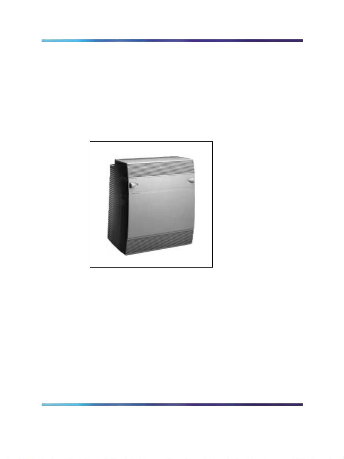
The NTAK11 cabinet is used for both main and expansion cabinets.
Figure 1 NTAK11 cabinet
Cable connectors
Connectors for cables to the cross-connect terminal and SDI ports are found
at the bottom of each cabinet.
The AUX, SDI, and Ethernet connectors are located at the bottom left-hand
side of the cabinet. The AUX port connects the cabinet to auxiliary
equipment such as a Power Failure Transfer Unit (PFTU). The SDI connector
in the main and IP expansion cabinets interfaces three SDI ports using a
three-port SDI cable. The Ethernet connector in the main cabinet provides
a 10 Mbit/s Ethernet port.
Communication Server 1000M and Meridian 1 Small System Installation and Commissioning
Copyright © 2008, Nortel Networks
.
Nortel Communication Server 1000
NN43011-310 01.04 Standard
Release 5.0 13 May 2008
Page 21
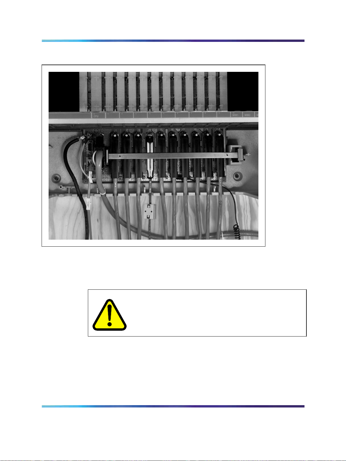
Figure 2 Cable connections
Signaling Server (for CS 1000M systems) 21
Cooling
The NTAK11 cabinet is designed to permit natural convection cooling. For
more information on requirements, refer to "Installing the Cabinet system"
(page 75).
WARNING
Do not block cabinet ventilation. Poor ventilation could cause the
system to overheat and damage system components, which may
result in service interruption.
Signaling Server (for CS 1000M systems)
The Signaling Server is an industry-standard, PC-based server. It provides
a central processor to drive the signaling for IP Phones and IP Peer
Networking.
The Signaling Server can be installed in a load-sharing redundant
configuration for higher scalability and reliability.
Communication Server 1000M and Meridian 1 Small System Installation and Commissioning
Copyright © 2008, Nortel Networks
.
Nortel Communication Server 1000
NN43011-310 01.04 Standard
Release 5.0 13 May 2008
Page 22
22 Cabinet system equipment
For information about installing and configuring the Signaling Server, refer
to Signaling Server Installation and Commissioning (NN43001-312).
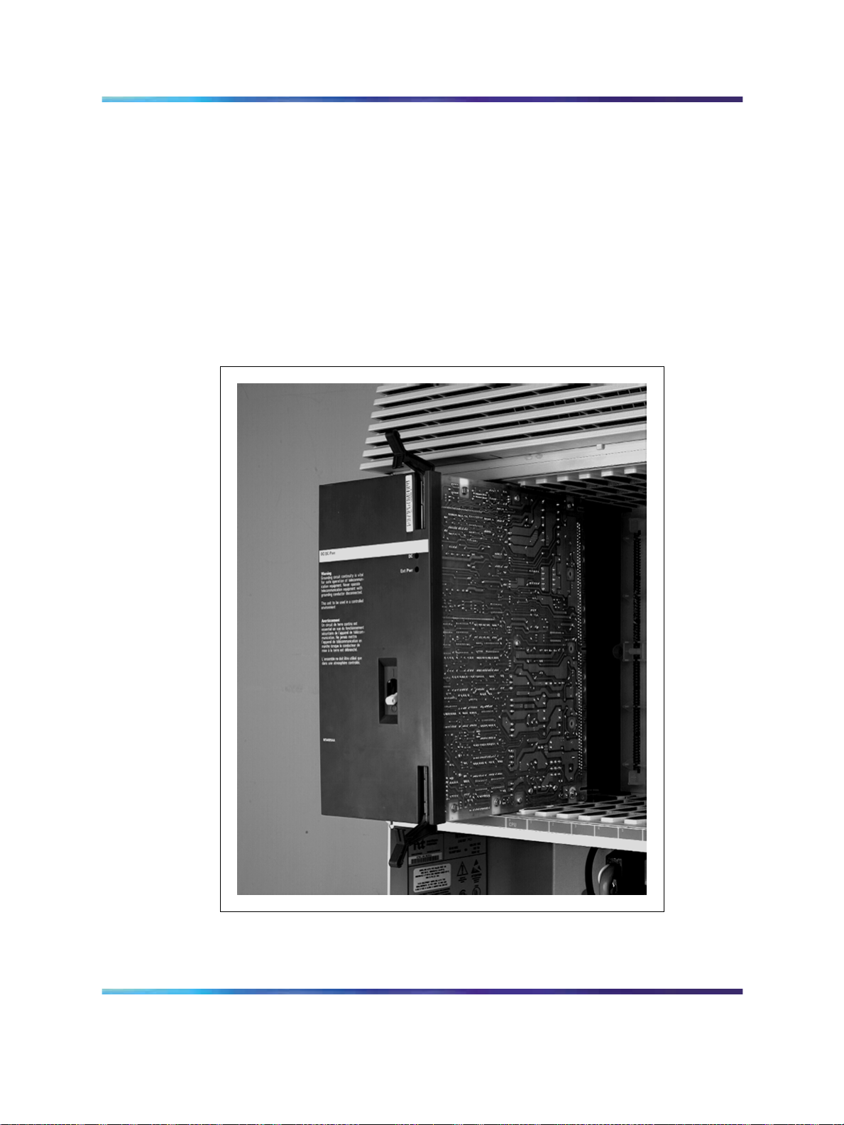
Power supplies
Two types of power supply are available for the system:
•
NTDK70 (for EMEA) AC power supply (see Figure 3 "AC/DC power
supply" (page 22))
•
NTDK72 DC power supply, used when the cabinet is powered by a -52
V DC source
Figure 3 AC/DC power supply
Communication Server 1000M and Meridian 1 Small System Installation and Commissioning
Copyright © 2008, Nortel Networks
.
Nortel Communication Server 1000
NN43011-310 01.04 Standard
Release 5.0 13 May 2008
Page 23

Reserve power
Three types of reserve battery power are supported:
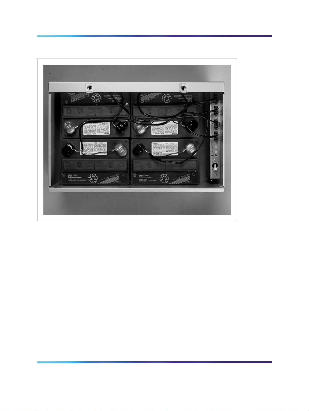
• The NTAK75 battery box (shown in Figure 4 "NTAK75 battery box" (page
•
•
Reserve power 23
CAUTION
Service Interruption
If the NTDK70 AC power supply is powered down while it is
operating on DC reserve power from a battery backup unit, the
Cabinet system cannot be powered up again until AC power is
restored. Be careful not to open the circuit breaker, either on
the battery backup unit, or on the NTDK70, while the system is
operating on battery backup.
24)) provides a minimum of two hours of reserve DC power.
The NTAK76 battery box (shown in Figure 5 "NTAK76 battery box" (page
25)) provides a minimum of 15 minutes of reserve DC power.
An Uninterruptible Power Supply (UPS) for continuous AC power supply.
Note: Customer-supplied battery backup units can be connected to the
cabinets using an NTAK28 Junction Box.
Communication Server 1000M and Meridian 1 Small System Installation and Commissioning
Copyright © 2008, Nortel Networks
.
Nortel Communication Server 1000
NN43011-310 01.04 Standard
Release 5.0 13 May 2008
Page 24
24 Cabinet system equipment
Figure 4 NTAK75 battery box
Communication Server 1000M and Meridian 1 Small System Installation and Commissioning
Copyright © 2008, Nortel Networks
.
Nortel Communication Server 1000
NN43011-310 01.04 Standard
Release 5.0 13 May 2008
Page 25
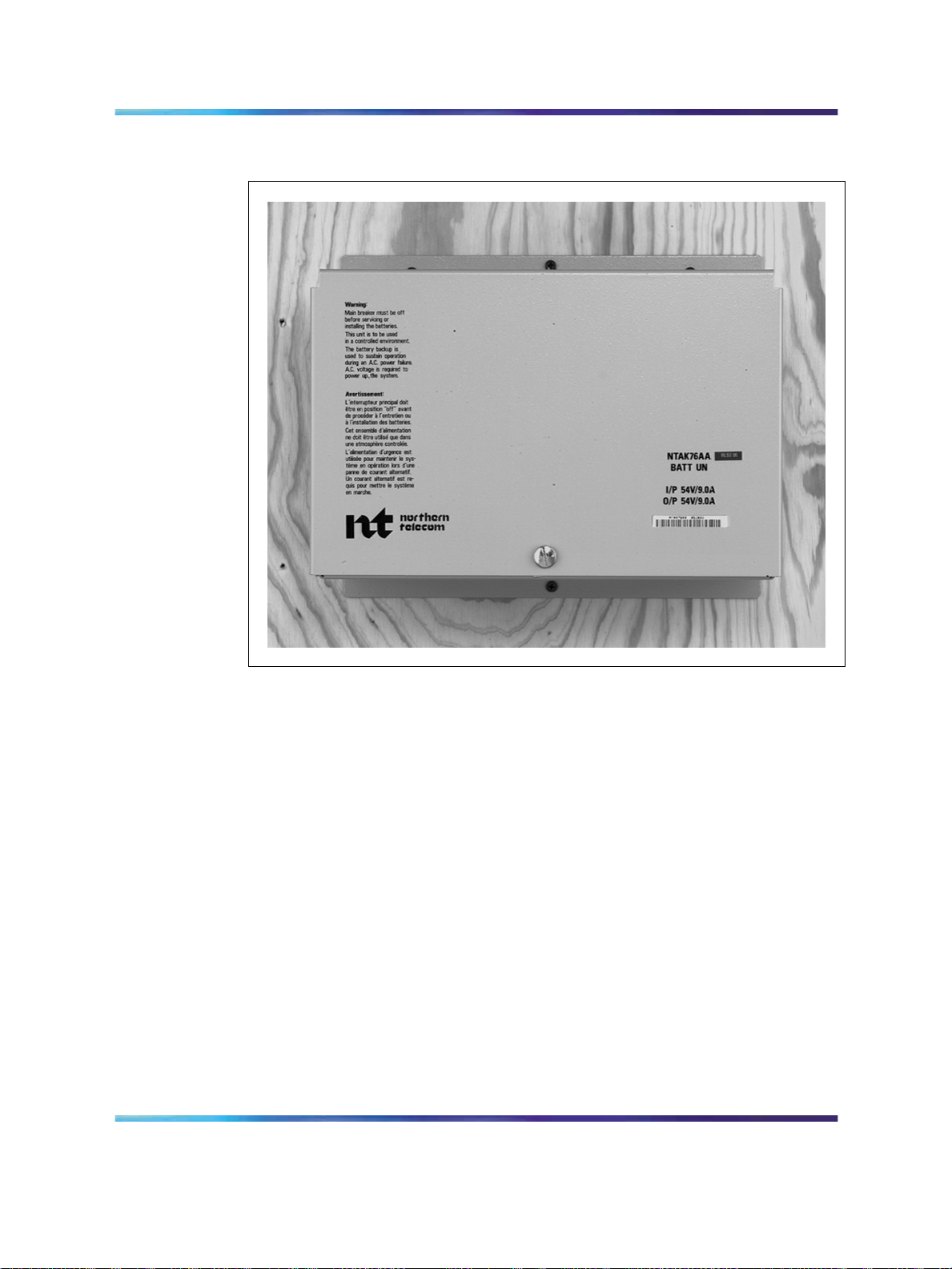
Figure 5 NTAK76 battery box
Common Equipment circuit cards and components 25
Common Equipment circuit cards and components
The circuit cards described in this section can be used in the main cabinet
and the IP expansion cabinets, where indicated.
Small System Controller card
The NTDK20 Small System Controller (SSC) card includes:
•
a Central Processing Unit (CPU) that handles call processing
•
an Ethernet controller
•
system memory
New systems are shipped with the NTDK20 SSC card, with 32 MB DRAM.
PC Card interface
The NTDK20 SSC card has a 2-slot PC Card interface socket located on
its faceplate (socket A is used for installations and upgrades, socket B is
used for backups). You can insert a Software Delivery card (PC Card) into
Communication Server 1000M and Meridian 1 Small System Installation and Commissioning
Copyright © 2008, Nortel Networks
.
Nortel Communication Server 1000
NN43011-310 01.04 Standard
Release 5.0 13 May 2008
Page 26

26 Cabinet system equipment
the socket. Use the PC Card for software upgrades on an existing Cabinet
system. You can also use this socket for creating an external backup copy
of the customer database.
Digitone receiver, tone generation, tone detection functions
The NTDK20 SSC card provides the following Digitone and other tone
functions related to tone:
•
30 channels of Tone and Digit Switch (TDS) and a combination of eight
Digitone receivers (DTR) or Dial Tone Detectors (XTD)
•
Tone service ports, which can be configured as either four units of
MFC/MFE/MFK5/MFK6/MFR or eight DTR/XTD units
Software daughterboard
The NTDK20 SSC card requires a software daughterboard in order to
function. The NTTK25 Software daughterboard provides storage for system
and customer data. It can be ordered preprogrammed with system software
and customer data.
For CS 1000 Release 4.5 software, the minimum requirements are:
•
32 MB DRAM
•
16 MB primary flash
•
32 MB program store
An NTDK20 SSC card with 32 MB DRAM and equipped with an NTTK25 or
NTTK13 Software daughterboard meets the minimum requirements.
Security device
A security device is required on the NTDK20 SSC card of the main and all
IP expansion cabinets. The SSC card is equipped with a socket designed
to hold the security device. The security device is shipped with each new
Cabinet system. When the SSC card is shipped, the security device is
normally not attached to the socket on the SSC card. You must attach the
security device to the SSC card during initial installation.
There are two types of security devices:
•
The NT_STD required in the main cabinet
•
The NT_REM required in the IP expansion cabinets
Note: The NT_REM is programmed to match the main cabinet device.
Both devices look identical, but can easily be identified by the label.
Communication Server 1000M and Meridian 1 Small System Installation and Commissioning
Copyright © 2008, Nortel Networks
.
Nortel Communication Server 1000
NN43011-310 01.04 Standard
Release 5.0 13 May 2008
Page 27
IP daughterboards
For IP connectivity, four IP daughterboards are available:
•
The NTDK99 single-port 100BaseT
•
The NTDK83 dual-port 100BaseT
•
The NTTK01 single-port 100BaseF
•
The NTTK02 dual-port 100BaseF
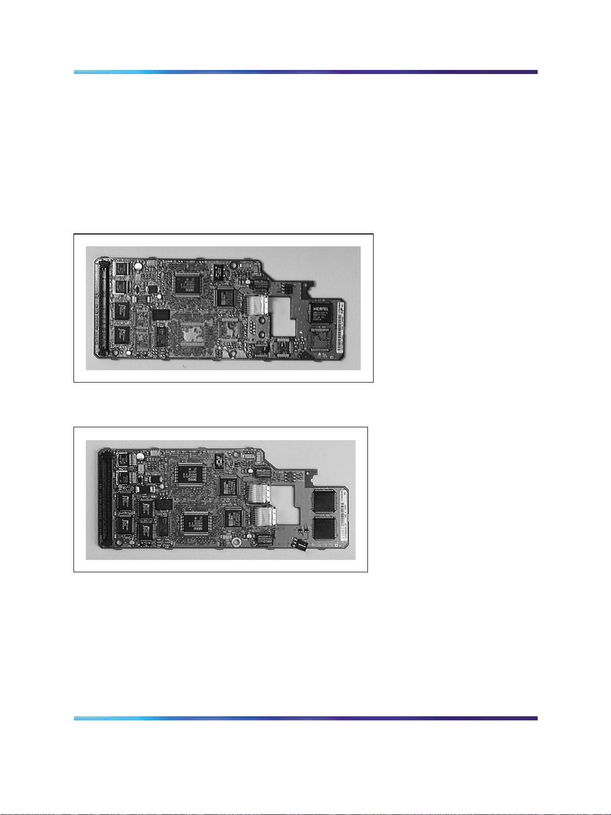
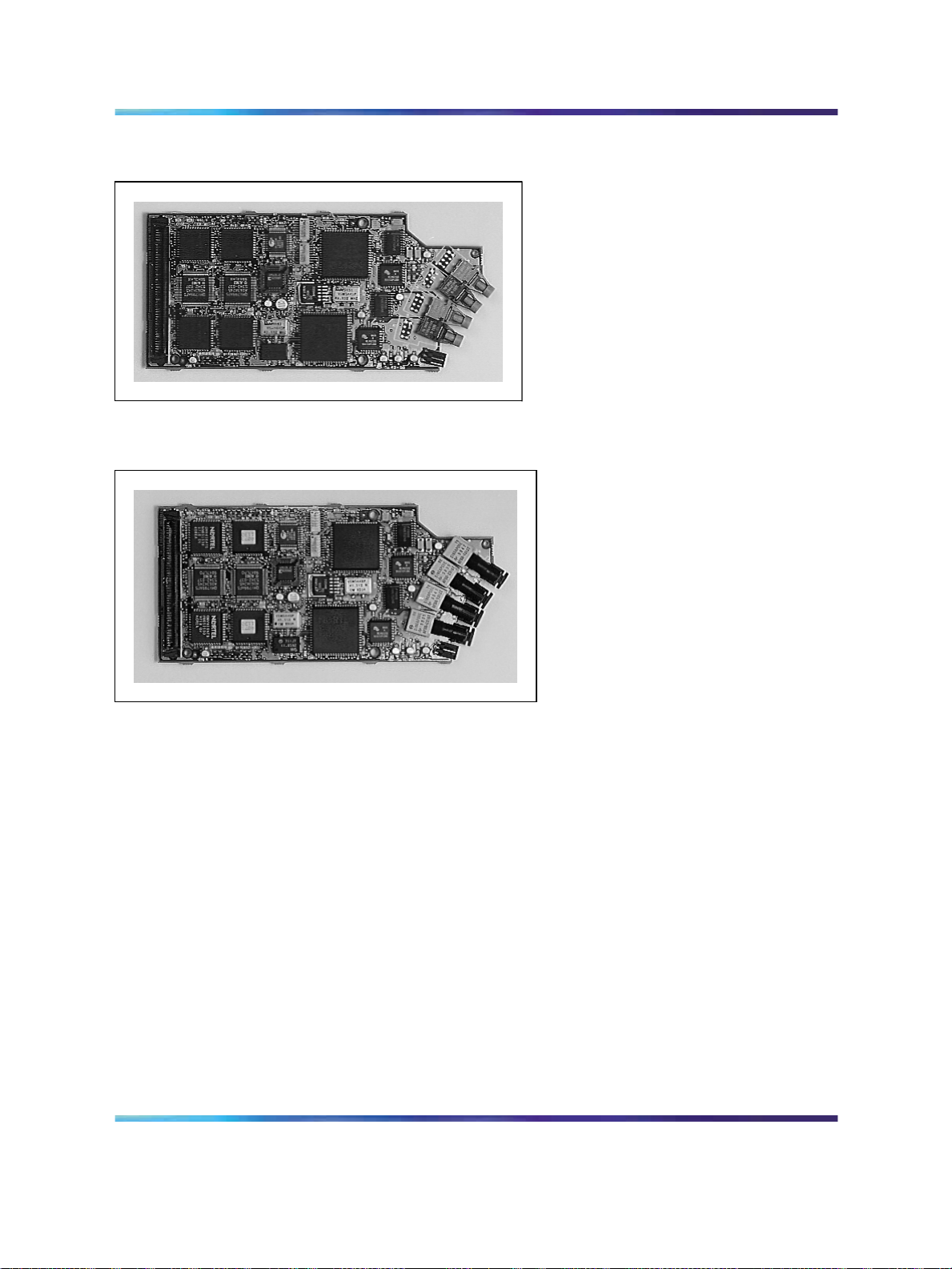
Figure 6 The NTDK99 Daughterboard
Common Equipment circuit cards and components 27
Figure 7 The NTDK83 IP Daughterboard
Communication Server 1000M and Meridian 1 Small System Installation and Commissioning
Copyright © 2008, Nortel Networks
.
Nortel Communication Server 1000
NN43011-310 01.04 Standard
Release 5.0 13 May 2008
Page 28
28 Cabinet system equipment
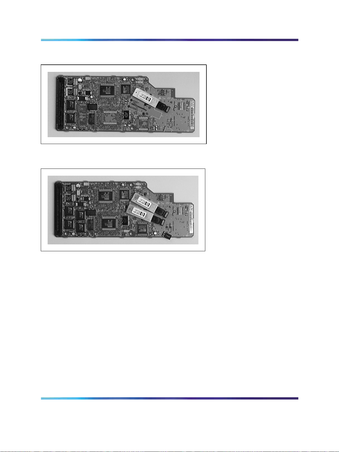
Figure 8 The NTTK01 Daughterboard
Figure 9 The NTTK02 IP Daughterboard
Fiber Expansion equipment
For non-IP expansion, fiber expansion daughterboards in the main cabinet
and fiber receiver cards in expansion cabinets allow for fiber connectivity
between the main cabinet and up to four fiber Expansion Cabinets or
Chassis.
Fiber Receiver card
There are three versions of the Fiber Receiver card. Each has a
corresponding Fiber Expansion daughterboard:
•
NTDK23 (10 m/33 ft, Plastic Multinode)
• NTDK25 (3 km/1.8 mi, Multimode)
•
NTDK80 (3 km/1.8 mi, Single Mode)
Communication Server 1000M and Meridian 1 Small System Installation and Commissioning
Copyright © 2008, Nortel Networks
.
Nortel Communication Server 1000
NN43011-310 01.04 Standard
Release 5.0 13 May 2008
Page 29
Common Equipment circuit cards and components 29
Fiber Expansion daughterboard
Single-port Fiber Expansion daughterboard The Single-port Fiber
Expansion daughterboards and their Fiber Receiver card counterparts are:
•
The NTDK22 Fiber Expansion daughterboard. Its Fiber Receiver card
counterpart is the NTDK23.
•
The NTDK24 daughterboard. Its Fiber Receiver card counterpart is
the NTDK25.
•
The NTDK79 daughterboard. Its Fiber Receiver card counterpart is
the NTDK80.
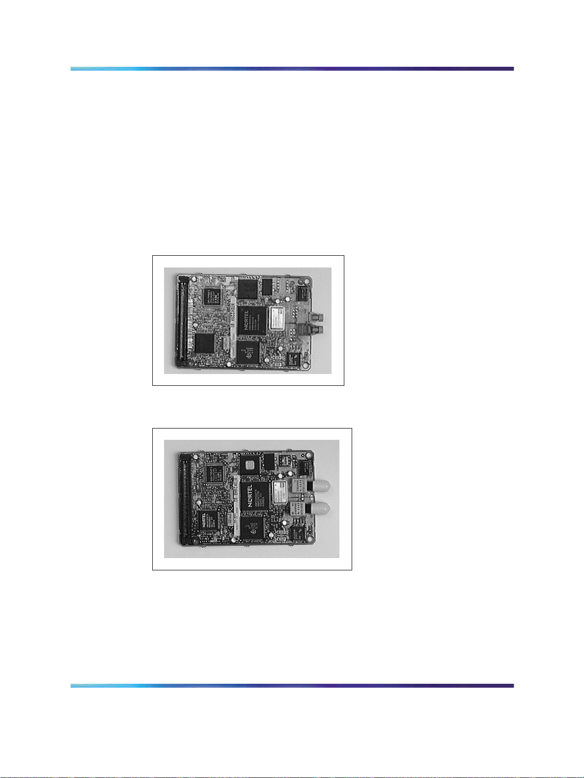
Figure 10 The NTDK22 Fiber Expansion daughterboard
Figure 11 The NTDK24 Daughterboard
Dual-port Fiber Expansion daughterboard The Dual-port Fiber
Expansion daughterboards and their Fiber Receiver counterparts are:
•
The NTDK84 Dual-port Fiber Expansion daughterboard. Its Fiber
Receiver card counterpart is the NTDK23.
• The NTDK85 daughterboard. Its Fiber Receiver card counterpart is
the NTDK25.
Communication Server 1000M and Meridian 1 Small System Installation and Commissioning
Copyright © 2008, Nortel Networks
.
Nortel Communication Server 1000
NN43011-310 01.04 Standard
Release 5.0 13 May 2008
Page 30
30 Cabinet system equipment
Figure 12 The NTDK84 Daughterboard
Figure 13 The NTDK85 Daughterboard
Communication Server 1000M and Meridian 1 Small System Installation and Commissioning
Copyright © 2008, Nortel Networks
.
Nortel Communication Server 1000
NN43011-310 01.04 Standard
Release 5.0 13 May 2008
Page 31

Common Equipment circuit cards and components 31
Figure 14 Daughterboards and security device on the NTDK20 SSC card
SDI/DCH card
The NTAK02 is an optional SDI/DCH card that provides four SDI ports for
various applications.
ISDN and DTI packs
Table 2 "Common equipment packs supported in Cabinet system IP
cabinets" (page 32) lists the packs required to support Integrated Services
Digital Networks (ISDN) and Digital Trunk Interface (DTI) functionality in
Cabinet systems.
Communication Server 1000M and Meridian 1 Small System Installation and Commissioning
Copyright © 2008, Nortel Networks
.
Nortel Communication Server 1000
NN43011-310 01.04 Standard
Release 5.0 13 May 2008
Page 32

32 Cabinet system equipment
Table 2 Common equipment packs supported in Cabinet system IP cabinets
Pack Daughterboard
1.5 MB TMDI (NTRB21) CC (NTAK20) downloadable DCH
2.0 MB DTI (NTAK20) n/a clock controller (stratum 3/4)
2.0 MB PRI (NTAK10) n/a clock controller (stratum 3/4)
2.0 MB PRI (NTBK50) DDCH (NTBK51)
CC (NTAK20)
MISP (NTBK22) CC (NTAK20) MISP BRI processor
SDI_DCH (NTAK02) n/a only DCH is supported; ESDI,
Card Option Mail is not supported n/a n/a
Supported application
clock controller (stratum 3/4)
DCH
downloadable DCH
clock controller (Stratum 3/4)
clock controller (stratum 3/4)
AML, TTY are not supported
Peripheral equipment cards
The following Intelligent Peripheral Equipment (IPE) cards can be used
in main and IP expansion cabinets:
•
NT1R20 Off-Premise Station (OPS) analog line card
• NT8D02 digital line card
•
NT8D03 analog line card
•
NT8DO9 analog message waiting line card
• NT8D14 Universal Trunk card
•
NT8D16 Digitone Receiver card
•
NT8D15 E&M Trunk card
• NT5D14 lineside T1 card
•
NT5D34 lineside E1 card
•
NT5K02 (International) analog line card
•
NT5K18 (International) 8 Port COT/PPM trunk card
•
NT5K17 (International) 8 Port DID trunk card
•
NT5K19 (International) 4 Port 2W/4W E&M, RAN, Paging AC15 trunk
card
•
NT5K21 (International) Multi Frequency Compelled Sender/Receiver
card
•
NT5K36 (International) 4 Port German DID/DOD trunk card
Communication Server 1000M and Meridian 1 Small System Installation and Commissioning
Copyright © 2008, Nortel Networks
.
Nortel Communication Server 1000
NN43011-310 01.04 Standard
Release 5.0 13 May 2008
Page 33

•
NT7D16 Data Access Card (DAC)
•
NTAG26 Extended Multi-frequency Receiver (XMFR) card
Telephones and attendant consoles
Supported telephones are as follows:
•
Analog (500/2500-type) telephones with or without message waiting
lamps.
•
Meridian Digital Telephones (M2006, M2008, M2216, M2616).
•
M2616 or M2216 Central Answering Position (CAP). This telephone
must be equipped with an ACD LCD display in order to function as a
CAP telephone.
•
Meridian 2250 (TCM) attendant consoles.
•
IP Phones (IP Phone 2001, IP Phone 2002, IP Phone 2004, and IP
Phone 2007)
•
IP Softphone 2050
Cables and wires 33
Converged Desktop
The Converged Desktop is a TDM or IP set configured to access Multimedia
Communication Server (MCS) 5100 multimedia applications through a
Session Initiation Protocol (SIP) Virtual Trunk.
CS 1000M Small Systems support the Converged Desktop.
Cables and wires
Glass fiber optic cable requirements
The Option 11C fiber optic link for distances up to 3 km (1.8 mi) uses the
industry standard 62.5/125 µm glass multi-mode duplex cable or 9/125 µm
glass Single Mode duplex cable with ST-type connectors.
The type of cable used depends on the type of installation and any local
building codes.
Table 3 "Multi and Single-mode glass optical cable requirements for
distances up to 3 km (1.8 mi)" (page 34) lists the optical requirements for
glass fiber optic cable used with the Option 11C.
Communication Server 1000M and Meridian 1 Small System Installation and Commissioning
Copyright © 2008, Nortel Networks
.
Nortel Communication Server 1000
NN43011-310 01.04 Standard
Release 5.0 13 May 2008
Page 34

34 Cabinet system equipment
Table 3 Multi and Single-mode glass optical cable requirements for distances up to 3 km (1.8 mi)
Parameter Minimum Typical Maximum Units
Glass Fiber Cable
Length
Cable Attenuation
1.5 (multi-mode)
@1300 nm
0.5 (Single Mode)
Modal Bandwidth
200 500
@1300 nm
Chromatic Dispersion
6
@1300 nm
Typical 3 dB Optical
180
Bandwidth
The fiber link is limited to a maximum length of 3 km. To guarantee reliable
operation, a bandwidth of 150% should be maintained. If the link is
increased beyond the 3 km length the 150% margin is deteriorated possibly
resulting in link malfunction under some conditions. Table 4 "Cabinet system
miscellaneous cables and wires" (page 34) lists miscellaneous cables and
wires used with the Chassis system.
Table 4 Cabinet system miscellaneous cables and wires
3.0
2.0 (multi-mode)
0.7 (Single Mode)
km
dB/km
MHz * km
ps/nm * km
MHz * km
Cable and wire
Purpose and description
A0632902 Fiber-optic cable (multi-mode plastic) Connects a main and expansion chassis by
interfacing with a fiber expansion daughterboard
and a Fiber Receiver card.
Length: 10 m (33 ft)
A0632902 Fiber-optic cable (multimode plastic) Connects a main and expansion cabinet by
interfacing with a fiber expansion daughterboard
and a Fiber Receiver card.
Length: 10 m (33 ft)
NE-A25B 25-pair cable Connects Intelligent Peripheral Equipment
cards to the cross-connect terminal. NE-A25B
connectors are on the back of each cabinet.
Note 1: This cable is available in different versions, depending on local EMC specifications.
Note 2: These cables are not supported under EMC specifications VL43.140P.
Communication Server 1000M and Meridian 1 Small System Installation and Commissioning
Copyright © 2008, Nortel Networks
.
Nortel Communication Server 1000
NN43011-310 01.04 Standard
Release 5.0 13 May 2008
Page 35

Cables and wires 35
Cable and wire
Purpose and description
NTAK19 cable SDI cable used with the NTAK02 circuit card
(see Note 1).
NTAK1118/1118 9- to 25-pin RS232 converter
Connects SDI ports and terminals (see Note 1).
cable
A0378652 F-F DCE to DTE converter, or
A0381016 F-M DCE to DTE converter
NTBK04 1.5 Mbit DTI/PRI carrier cable
(A0394216)
Connects SDI ports to equipment, such as TTYs
and modems.
Connects the NTAK09 1.5 Mbit DTI/PRI card to
the Channel Service Unit (CSU). The NTBK04
carries Tx and Rx pairs to a standard 5-pin
connector.
NTBK05AA/DA 2.0 Mbit DTI/PRI carrier cable
A0394217
Carries Tx and Rx pairs to a standard 120-Ohm
D-connector (see Note 1).
NT8D7205 DTI/PRI carrier cable
NTBK05CA coaxial cable
NTBK05DA twisted pair cable
NTAK10 2.0 Mbit DTI cable
These cables provide DTI/PRI connections. The
cables carry Tx and Rx pairs to a standard 5-pin
connector (see Note 2).
NTAK79 2.0 Mbit PRI cable
NTAK50 2.0 Mbit PRI cable
25-pair inside wiring cables equipped with
amphenol-type connectors
Extend the Intelligent Peripheral Equipment
connections from the system chassis to the
cross-connect terminal, and connect PFTUs.
#6 AWG (#40 Metric Wire Gauge) insulated
ground wire
Connects a system cabinet to a building ground
source.
#6 AWG (10 mm2) insulated ground wire (UK) Connects a system cabinet to a building ground
source.
#6 AWG (20 mm2) insulated ground wire
Connects a cabinet to a building ground source.
(Europe)
#8 AWG (10 mm2) insulated ground wire
Connects a cabinet to a building ground source.
(Germany)
Cross-connect wire Makes cross connections at the cross-connect
terminal.
Note 1: This cable is available in different versions, depending on local EMC specifications.
Note 2: These cables are not supported under EMC specifications VL43.140P.
Table 5 "AC power cord kits" (page 36) lists the AC power cord kits for
various countries. These cords connect a system cabinet to a commercial
AC power source.
Communication Server 1000M and Meridian 1 Small System Installation and Commissioning
Copyright © 2008, Nortel Networks
.
Nortel Communication Server 1000
NN43011-310 01.04 Standard
Release 5.0 13 May 2008
Page 36

36 Cabinet system equipment
Table 5 AC power cord kits
AC Power
Country or region
North America A0379412 250 V 10 A NEMA 6-15P
Argentina A0814961 250 V 10 A IRAM 2073
North America NTTK14 125 V 13 A NEMA 5-15P
Australia/New Zealand NTTK15 250 V 10 A AS3112
Europe NTTK16 250 V 10 A CEE(7)VII
Switzerland NTTK17 250 V 10 A SEV 1011
UK/Ireland NTTK18 250 V 10 A BS1363
Denmark NTTK22 250 V 10 A AFSNIT
Cord
Voltage
Rating
Current
Rating Plug Type
Miscellaneous items
The following is a list of typical miscellaneous items that can be used as
part of the system installation. Quantities needed depend on the site and
customer requirements:
•
QUA6 Power Failure Transfer Units (PFTU) to transfer lines during a
power or system failure
• NTBK80 grounding block
•
modems or Data Communication Equipment (DCE) for remote access
to the system
•
on-site Data Terminating Equipment (DTE) or teletypewriter (TTY)
terminal for accessing the system
•
connecting blocks for the cross-connect terminal
•
transformers and centralized power supplies for items such as digit
displays on telephones
•
optional equipment such as music sources, RAN machines, paging
equipment, and CDR devices
•
NT1R20 Off-Premise Station Analog Line Card. Each card has eight
ports. Each of the units on the card can be configured to be operated as
an OPS or in an On-Premise (ONS) configuration
•
additional Modem Eliminator (NULL Modem without hardware
handshaking) A0601397 converter may be required to interface the
DTE to the system
•
NTTK41 EMC grounding clip is required, for EMC compliance, on the
front stiffener rail of cabinets using 100BaseT connections. Refer to
Figure 15 "EMC grounding clip on the cabinet" (page 37).
Communication Server 1000M and Meridian 1 Small System Installation and Commissioning
Copyright © 2008, Nortel Networks
.
Nortel Communication Server 1000
NN43011-310 01.04 Standard
Release 5.0 13 May 2008
Page 37

Figure 15 EMC grounding clip on the cabinet
Miscellaneous items 37
Communication Server 1000M and Meridian 1 Small System Installation and Commissioning
Copyright © 2008, Nortel Networks
.
Nortel Communication Server 1000
NN43011-310 01.04 Standard
Release 5.0 13 May 2008
Page 38

38 Cabinet system equipment
Communication Server 1000M and Meridian 1 Small System Installation and Commissioning
Copyright © 2008, Nortel Networks
.
Nortel Communication Server 1000
NN43011-310 01.04 Standard
Release 5.0 13 May 2008
Page 39

Chassis system equipment
Contents
This section contains information on the following topics:
"Introduction" (page 39)
"Main components of the Chassis system" (page 39)
"NTDK91 chassis and NTDK92 chassis expander" (page 39)
"Signaling Server (for CS 1000M systems)" (page 43)
"Power supply" (page 43)
"Reserve power supply" (page 45)
"Circuit cards" (page 46)
"IP daughterboards" (page 27)
"Lineside E1/T1 cards" (page 48)
"Fiber expansion" (page 48)
39
"Telephones and attendant consoles" (page 48)
"Cables and wires" (page 49)
"Miscellaneous items for installation" (page 52)
Introduction
This chapter describes the main components used to install the Chassis
system. This chapter also describes the differences between the Chassis
system and the Cabinet system.
For a description of the Signaling Server for a CS 1000M Chassis, refer to
Signaling Server Installation and Commissioning (NN43001-312).
Main components of the Chassis system
NTDK91 chassis and NTDK92 chassis expander
A Chassis system comprises an NTDK91 chassis plus an optional NTDK92
chassis expander. The chassis can be connected to the chassis expander
to increase line capacity.
Communication Server 1000M and Meridian 1 Small System Installation and Commissioning
Copyright © 2008, Nortel Networks
.
Nortel Communication Server 1000
NN43011-310 01.04 Standard
Release 5.0 13 May 2008
Page 40

40 Chassis system equipment
The chassis supports the following:
•
NTDK20 Small System Controller (SSC) card installed in slot 0
•
any IPE or CE card in slots 1, 2, and 3
•
a dedicated 48-port Digital Line Card (NTDK16) in slot 4
The chassis expander supports the following:
•
Meridian Mail in slot 10 only.
•
With Meridian Mail in slot 10, you can insert any IPE card in slots 7,
8, and 9.
Chassis installation options
You can install the chassis and chassis expander in the following positions:
•
in a rack/equipment cabinet
•
on a wall
— vertically on a wall
— horizontally on a wall
The following chassis installation kits are available:
•
NTTK08AA: for vertical, wall installation
•
NTTK09AA: for rack/cabinet installation
•
NTTK11AA: for horizontal, wall installation
Cable connectors
25-pair cables connect cards to the cross-connect terminal. Connectors for
these cables are on the back of the chassis and the chassis expander. See
Figure 16 "25-pair cable connectors on the back of the chassis" (page 41).
Communication Server 1000M and Meridian 1 Small System Installation and Commissioning
Copyright © 2008, Nortel Networks
.
Nortel Communication Server 1000
NN43011-310 01.04 Standard
Release 5.0 13 May 2008
Page 41

Figure 16 25-pair cable connectors on the back of the chassis
Main components of the Chassis system 41
The Auxiliary (AUX), Serial Data Interface (SDI), and Ethernet connectors
are on the back left-hand side of the chassis. See Figure 17 "Connectors on
the back of the chassis" (page 42).
The AUX port connects auxiliary equipment, such as a Power Failure
Transfer Unit (PFTU), to the Chassis system. The SDI connector in the
chassis interfaces three SDI ports using a three-port SDI cable. The
Ethernet connector in the chassis provides a 10 Mbit Ethernet network
interface. The Ethernet network interface accepts an industry-standard
Media Access Unit (MAU). Insert the Cat5 Ethernet cable into this MAU.
The back of the chassis also contains connectors for connecting the
chassis and the chassis expander. These connectors are for the DS-30X
and CE-MUX connections. See Figure 17 "Connectors on the back of the
chassis" (page 42).
The power connector is at the back of the chassis on the upper left-hand
side. See Figure 17 "Connectors on the back of the chassis" (page 42).
Secure the power cord with a cable tie.
Communication Server 1000M and Meridian 1 Small System Installation and Commissioning
Copyright © 2008, Nortel Networks
.
Nortel Communication Server 1000
NN43011-310 01.04 Standard
Release 5.0 13 May 2008
Page 42

42 Chassis system equipment
Figure 17 Connectors on the back of the chassis
Figure 18 "Connectors on the back of the chassis expander" (page
42) shows the connectors on the back of the chassis expander.
Figure 18 Connectors on the back of the chassis expander
Communication Server 1000M and Meridian 1 Small System Installation and Commissioning
Copyright © 2008, Nortel Networks
.
Nortel Communication Server 1000
NN43011-310 01.04 Standard
Release 5.0 13 May 2008
Page 43

Main components of the Chassis system 43
Cooling
The NTDK91 chassis and the NTDK92 chassis expander have forced air
cooling. As a result, you can install the chassis in a horizontal or vertical
position. The fan inside the chassis is controlled by heat. It runs at a
reduced speed at room temperature.
WARNING
Do not block chassis ventilation. Poor ventilation could cause the
system to overheat and damage system components, which may
result in service interruption.
Signaling Server (for CS 1000M systems)
The Signaling Server is an industry-standard, PC-based server. It provides
a central processor to drive the signaling for IP Phones and IP Peer
Networking.
The Signaling Server can be installed in a load-sharing redundant
configuration for higher scalability and reliability.
For information about installing and configuring the Signaling Server, refer
to Signaling Server Installation and Commissioning (NN43001-312).
Power supply
The universal power supply in the Chassis system uses AC input. The
power supply is factory installed and not customer replaceable. The Chassis
system does not support DC input.
Power switch
There is a power switch on the front of the NTDK91 chassis and the
NTDK92 chassis expander. Use this switch to turn the system power on and
off. See Figure 19 "Front of chassis" (page 45).
Power status indicator
There is a power status indicator (LED) on the front cover (top left-hand
corner) of the chassis and the chassis expander. When the LED is green,
the power is in operation. When the LED is off, there is a power failure of
one of the power outputs. See Figure 19 "Front of chassis" (page 45).
Power supply DIP switch settings
Use a DIP switch to set ringing voltages, ringing frequencies, and message
waiting voltages. See Table 7 "Asia Pacific/CALA power supply DIP switch
settings" (page 44) and Figure 19 "Front of chassis" (page 45) for all DIP
switch setting options. Typical settings are shown for the following regions:
•
Table 7 "Asia Pacific/CALA power supply DIP switch settings" (page 44)
Communication Server 1000M and Meridian 1 Small System Installation and Commissioning
Copyright © 2008, Nortel Networks
.
Nortel Communication Server 1000
NN43011-310 01.04 Standard
Release 5.0 13 May 2008
Page 44

44 Chassis system equipment
•
Table 8 "Europe power supply DIP switch settings" (page 44)
•
Table 9 "North American power supply DIP switch settings" (page 45)
Table 6 Power supply DIP switch settings
Ringing Frequency (Hz) Ringing Amplitude (Vrms) Message Waiting Lamp
(VDC)
Swit
ch
Setti
ng
1
2
20 25 50
ON OFF ON
ON ON OFF
Swit
ch
Setti
ng
3
4
5
70
OFF ON ON ON
OFF OFF ON ON
OFF OFF OFF ON
75
80 86
Swit
ch
Setti
ng
6
7
8
-120 -150
NOT USED
OFF OFF ON
OFF ON X
Table 7
Asia Pacific/CALA power supply DIP switch settings
Ringing Frequency (Hz) Ringing Amplitude (Vrms) Message Waiting Lamp
(VDC)
Swit
ch
Setti
ng
1
2
20 25 50
OFF
ON
Swit
ch
Setti
ng
3
4
5
70
75
ON
OFF
OFF
80 86
Swit
ch
Setti
ng
6
7
8
-120 -150
NOT USED
OFF
ON
Disa
ble
Disa
ble
Table 8 Europe power supply DIP switch settings
Ringing Frequency (Hz) Ringing Amplitude (Vrms) Message Waiting Lamp
(VDC)
Swit
ch
Setti
20 25 50
Switc
h Set
ting
70
75
80 86
Switc
h Set
ting
-120 -150
ng
1
2
Communication Server 1000M and Meridian 1 Small System Installation and Commissioning
Copyright © 2008, Nortel Networks
.
OFF
ON
3
4
5
Nortel Communication Server 1000
NN43011-310 01.04 Standard
Release 5.0 13 May 2008
ON
OFF
OFF
6
NOT USED
7
8
Disa
ble
ON
ON
Page 45

Main components of the Chassis system 45
Table 9 North American power supply DIP switch settings
Ringing Frequency (Hz) Ringing Amplitude (Vrms) Message Waiting Lamp
(VDC)
Swit
ch
Setti
ng
1
2
20 25 50
ON
ON
Swit
ch
Setti
ng
3
4
5
70
75
80 86
ON
ON
ON
Swit
ch
Setti
ng
6
7
8
-120 -150
NOT USED
Note: Set the DIP switches before the system powers up.
Figure 19 "Front of chassis" (page 45) shows the power switch, power status
indicator, and DIP switch settings.
Figure 19 Front of chassis
Disa
ble
ON
ON
Reserve power supply
You can use an Uninterruptible Power Supply (UPS) to provide a backup
power supply for the NTDK91 and the NTDK92 chassis. A UPS provides
a continuous AC power supply. Install the UPS unit according to the
manufacturer’s instructions. Refer to the power consumption information
in the chapters on system and site requirements in Communication
Communication Server 1000M and Meridian 1 Small System Installation and Commissioning
Copyright © 2008, Nortel Networks
.
Nortel Communication Server 1000
NN43011-310 01.04 Standard
Release 5.0 13 May 2008
Page 46

46 Chassis system equipment
Server 1000M and Meridian 1 Small System Planning and Engineering
(NN43011-220). This section contains worksheets to help you determine
the power draw for the UPS.
Circuit cards
The Chassis system supports the NTDK20 SSC card and the NTDK16
48-port Digital Line Card. This section provides a short overview of these
two cards. For more information about other circuit cards supported on the
Chassis system, refer to "Installing optional circuit cards" (page 193).
NTDK20 SSC card and components
The NTDK20 SSC card includes:
•
a Central Processing Unit (CPU) that handles call processing
•
an Ethernet controller
•
system memory
New systems are shipped with the NTDK20 SSC card, with 32 MB DRAM.
You must install the SSC card in slot 0.
Software Daughterboard
The NTDK20 SSC card requires a software daughterboard in order to
function. The NTTK25 Software daughterboard provides 64 MB of storage
for system and customer data. It can be ordered preprogrammed with
system software and customer data.
For CS 1000 Release 4.5 software, the minimum requirements are:
•
32 MB DRAM
•
16 MB primary flash
•
32 MB program store
An NTDK20 SSC card with 32 MB DRAM and equipped with an NTTK13 or
NTTK25 Software daughterboard meets the minimum requirements.
PC Card interface The NTDK20 SSC card has a 2-slot PC Card interface
socket located on its faceplate (socket A is used for installations and
upgrades, socket B is used for backups). You can insert a Software Delivery
card (PC Card) into the socket. Use the PC Card for software upgrades on
an existing Chassis system. You can also use this socket for creating an
external backup copy of the customer database.
SDI ports The NTDK20 SSC card contains three SDI ports used to
connect on-site terminals or remote terminals through a modem.
Communication Server 1000M and Meridian 1 Small System Installation and Commissioning
Copyright © 2008, Nortel Networks
.
Nortel Communication Server 1000
NN43011-310 01.04 Standard
Release 5.0 13 May 2008
Page 47

Main components of the Chassis system 47
Ethernet network interface The NTDK20 SSC card has a 10 Mbit
Ethernet network interface. The 15-pin connector, located on the back of
the chassis, provides external connection to the Ethernet network interface.
This connector is for a standard 15-pin AUI interface for a MAU.
Digitone receiver, tone generation, tone detection functions The
NTDK20 SSC card provides the following Digitone and other tone functions
related to tone:
•
30 channels of Tone and Digit Switch (TDS) and a combination of eight
Digitone receivers (DTR) or Dial Tone Detectors (XTD)
•
Tone service ports, which can be configured as either four units of
MFC/MFE/MFK5/MFK6/MFR or eight DTR/XTD units
Security device
A security device is required on the NTDK20 SSC card of the main and all
IP chassis expanders. The SSC card is equipped with a socket designed
to hold the security device. The security device is shipped with each new
Chassis system. When the SSC card is shipped, the security device is
normally not attached to the socket on the SSC card. You must attach the
security device to the SSC card during initial installation.
There are two types of security devices:
•
The NT_STD required in the main chassis
•
The NT_REM required in the IP chassis expanders
Note: The NT_REM is programmed to match the main chassis device.
Both devices look identical, but can easily be identified by the label.
NTDK16 48-port Digital Line Card
The NTDK16 48-port Digital Line Card provides an interface to a maximum
of 48 digital integrated voice and 48 data ports. The NTDK16 Digital Line
Card is functionally equivalent to three NT8D02 Digital Line Cards.
Note 1: Only place the NTDK16 Digital Line Card in slot 4 of the chassis.
Note 2: The NTDK16 Digital Line Card is not required for the Chassis
system to operate.
IP expansion
For IP connectivity, four IP daughterboards are available:
•
The NTDK99 single-port 100BaseT
•
The NTDK83 dual-port 100BaseT
•
The NTTK01 single-port 100BaseF
Communication Server 1000M and Meridian 1 Small System Installation and Commissioning
Copyright © 2008, Nortel Networks
.
Nortel Communication Server 1000
NN43011-310 01.04 Standard
Release 5.0 13 May 2008
Page 48

48 Chassis system equipment
•
The NTTK02 dual-port 100BaseF
Lineside E1/T1 cards
The Chassis system also supports the following lineside cards:
•
NT5D14 lineside T1
•
NT5D34 lineside E1
For further information about T1/E1 lineside cards, refer to Circuit Card
Reference (NN43001-311).
Fiber expansion
For non-IP expansion, fiber expansion daughterboards in the chassis and
Fiber Receiver cards in the expansion chassis allow for fiber connectivity
between the chassis and up to four fiber expansion chassis or cabinets.
Fiber Receiver card
Multi-chassis Small Systems require an NTDK23 Fiber Receiver card in
each additional chassis. The NTDK23 supports a 10 m (33 ft) plastic
fiber-optic cable. Each Fiber Receiver card provides one SDI port for
remote TTY access.
Fiber Expansion daughterboard
Fiber expansion daughterboards must be installed on the NTDK20 SSC
card in order to connect to additional chassis. There are two kinds of fiber
expansion daughterboards that can be matched with the NTDK23 Fiber
Receiver card:
•
NTDK22 Single-port Fiber Expansion daughterboard
•
NTDK84 Dual-port Fiber Expansion daughterboard
Both daughterboards are used with the A0632902 Fiber-optic (multimode)
cable.
Routing Guides
Each chassis in a multi-chassis system requires a Routing Guide, in order
to route and manage the fiber-optic cable. Only one guide is required
in each chassis.
Telephones and attendant consoles
The Chassis system supports the following telephones and attendant
consoles:
• Analog (500/2500-type) telephones, with or without message waiting
lamps
•
Meridian Digital Telephones (M2006, M2008, M2216, M2616)
Communication Server 1000M and Meridian 1 Small System Installation and Commissioning
Copyright © 2008, Nortel Networks
.
Nortel Communication Server 1000
NN43011-310 01.04 Standard
Release 5.0 13 May 2008
Page 49

Main components of the Chassis system 49
•
Meridian Digital Telephones (M3110, M3310, and M3820)
Note: The M3110, M3310, and M3820 Meridian Digital Telephones
are available in Europe only.
•
Meridian Digital Telephones (M3901, M3902, M3903, M3904, and
M3905)
Note: Only the M3901 and the M3905 Meridian Digital Telephones
are supported in Europe.
•
M2616 or M2216 Central Answering Position (CAP). These telephones
must have an ACD LCD display installed to function as a CAP telephone.
•
Taurus sets
•
Meridian 2250 (TCM) attendant consoles
•
IP Phones (IP Phone 2001, IP Phone 2002, IP Phone 2004, IP Phone
2007, IP Audio Conference Phone 2033)
•
IP Softphone 2050
•
Attendant PC
Converged Desktop
The Converged Desktop is a TDM or IP set configured to access Multimedia
Communication Server (MCS) 5100 multimedia applications through a
Session Initiation Protocol (SIP) Virtual Trunk.
CS 1000M Small Systems support the Converged Desktop.
Cables and wires
Table 10 "Chassis system cable kits" (page 49) lists Chassis system cable
kits and their contents.
Table 10 Chassis system cable kits
Cable or wire Purpose/description
NTDK88 Main cable kit
NTBK48 three-port SDI cable Connects equipment, such as TTYs and modems,
to the Chassis system. Use the NTBK48 with the
NTDK20 SSC card.
NTAK1104 AUX cable Connects a PFTU to a system chassis.
A0601396 F-M DCE to DTE converter You can use the A0601396 when connecting SDI
ports to equipment, such as TTYs and modems.
Communication Server 1000M and Meridian 1 Small System Installation and Commissioning
Copyright © 2008, Nortel Networks
.
Nortel Communication Server 1000
NN43011-310 01.04 Standard
Release 5.0 13 May 2008
Page 50

50 Chassis system equipment
Cable or wire Purpose/description
A0601397 F-F DCE to DTE converter You can use the A0501397 when connecting SDI
ports to equipment such as TTYs and modems.
NTDK89 chassis expander cable kit
NTDK95 CE-MUX/DS-30X bus cable Connects the chassis to the chassis expander. You
need two of these cables to connect the chassis and
the chassis expander. Length: 0.6 m (2 ft)
A0632902 Fiber Optic cable (multimode
plastic)
Glass Fiber Optic (multimode or single
mode, depending on interface) cable up to
3 km (1.8 mi)
Connects a Main and Expansion chassis by
interfacing with an expansion daughterboard and a
Fiber Receiver card. Length: 10 m (33 ft)
Must be supplied locally by a facilities provider.
Length up to 3 km (1.8 mi)
Table 11 "AC power cord kits" (page 50) lists the AC power cord kits for
various countries. These cords connect a system chassis to a commercial
AC power source.
Table 11 AC power cord kits
AC Power
Country or region
North America A0379412 250 V 10 A NEMA 6-15P
Argentina A0814961 250 V 10 A IRAM 2073
North America NTTK14 125 V 13 A NEMA5-15P
Australia/New Zealand NTTK15 250 V 10 A AS3112
Europe NTTK16 250 V 10 A CEE(7)VII
Cord
Voltage
Rating
Current
Rating Plug Type
Switzerland NTTK17 250 V 10 A SEV 1011
UK/Ireland NTTK18 250 V 10 A BS1363
Denmark NTTK22 250 V 10 A AFSNIT
Glass fiber optic cable requirements
The Option 11C fiber optic link for distances up to 3 km (1.8 mi) uses the
industry standard 62.5/125 µm glass multimode duplex cable or 9/125 µm
glass Single Mode duplex cable with ST-type connectors.
The type of cable used depends on the type of installation and any local
building codes.
Table 12 "Multi and Single-mode glass optical cable requirements for
distances up to 3 km (1.8 mi)" (page 51) lists the optical requirements for
glass fiber optic cable used with the Option 11C.
Communication Server 1000M and Meridian 1 Small System Installation and Commissioning
Copyright © 2008, Nortel Networks
.
Nortel Communication Server 1000
NN43011-310 01.04 Standard
Release 5.0 13 May 2008
Page 51

Main components of the Chassis system 51
Table 12 Multi and Single-mode glass optical cable requirements for distances up to 3 km (1.8 mi)
Parameter Minimum Typical Maximum Units
Glass Fiber Cable Length
Cable Attenuation @1300
1.5 (multimode)
nm
0.5 (Single Mode)
Modal Bandwidth @1300
200 500
nm
Chromatic Dispersion
6
@1300 nm
Typical 3 dB Optical
180
Bandwidth
The fiber link is limited to a maximum length of 3 km. To guarantee reliable
operation, a bandwidth of 150% should be maintained. If the link is
increased beyond the 3 km length the 150% margin is deteriorated possibly
resulting in link malfunction under some conditions.Table 13 "Chassis
system miscellaneous cables and wires" (page 51) lists miscellaneous
cables and wires used with the Chassis system.
Table 13 Chassis system miscellaneous cables and wires
3.0
2.0 (multimode)
0.7 (Single Mode)
km
dB/km
MHz *
km
ps/nm *
km
MHz *
km
Cable and wire
A0632902 Fiber-optic cable (multimode
plastic)
Purpose and description
Connects a main and expansion chassis by interfacing
with a fiber expansion daughterboard and a Fiber
Receiver card. Length: 10 m (33 ft)
A0632902 Fiber-optic cable (multimode
plastic)
Connects a main and expansion chassis by interfacing
with a fiber expansion daughterboard and a Fiber
Receiver card. Length: 10 m (33 ft)
NE-A25B 25-pair cable Connects Intelligent Peripheral Equipment cards to
the cross-connect terminal. NE-A25B connectors are
on the back of each chassis.
NTAK19 cable SDI cable used with the NTAK02 circuit card (see
Note 1).
Note 1: This cable is available in different versions, depending on local EMC specifications.
Note 2: These cables are not supported under EMC specifications VL43.140P.
Communication Server 1000M and Meridian 1 Small System Installation and Commissioning
Copyright © 2008, Nortel Networks
.
Nortel Communication Server 1000
NN43011-310 01.04 Standard
Release 5.0 13 May 2008
Page 52

52 Chassis system equipment
Cable and wire
NTAK1118/1118 9- to 25-pin RS232
Purpose and description
Connects SDI ports and terminals (see Note 1).
converter cable
A0378652 F-F DCE to DTE converter, or
A0381016 F-M DCE to DTE converter
NTBK04 1.5 Mbit DTI/PRI carrier cable
(A0394216)
Connects SDI ports to equipment, such as TTYs and
modems.
Connects the NTAK09 1.5 Mbit DTI/PRI card to the
Channel Service Unit (CSU). The NTBK04 carries Tx
and Rx pairs to a standard 5-pin connector.
NTBK05AA/DA 2.0 Mbit DTI/PRI carrier
cable A0394217
Carries Tx and Rx pairs to a standard 120-Ohm
D-connector (see Note 1).
NT8D7205 DTI/PRI carrier cable
NTBK05CA coaxial cable NTBK05DA
twisted pair cable NTAK10 2.0 Mbit DTI
cable NTAK79 2.0 Mbit PRI cable NTAK50
These cables provide DTI/PRI connections. The
cables carry Tx and Rx pairs to a standard 5-pin
connector (see Note 2).
2.0 Mbit PRI cable
25-pair inside wiring cables equipped with
amphenol-type connectors
Extend the Intelligent Peripheral Equipment
connections from the system chassis to the
cross-connect terminal, and connect PFTUs.
#6 AWG (#40 Metric Wire Gauge) insulated
ground wire
#6 AWG (10 mm2) insulated ground wire
(UK)
Connects a system chassis to a building ground
source.
Connects a system chassis to a building ground
source.
#6 AWG (20 mm2) insulated ground wire
Connects a chassis to a building ground source.
(Europe)
#8 AWG (10 mm2) insulated ground wire
Connects a chassis to a building ground source.
(Germany)
Cross-connect wire Makes cross connections at the cross-connect
terminal.
Note 1: This cable is available in different versions, depending on local EMC specifications.
Note 2: These cables are not supported under EMC specifications VL43.140P.
Miscellaneous items for installation
The following is a list of miscellaneous items that you can use as part of
Chassis system installation. Quantities needed depend on the site and
customer requirements:
•
QUA6 Power Failure Transfer Units (PFTU) to transfer lines during a
power or system failure
•
NTBK80 grounding block
Communication Server 1000M and Meridian 1 Small System Installation and Commissioning
Copyright © 2008, Nortel Networks
.
Nortel Communication Server 1000
NN43011-310 01.04 Standard
Release 5.0 13 May 2008
Page 53

Main components of the Chassis system 53
•
modems or Data Communication Equipment (DCE) for remote access
to the system
•
on-site Data Terminating Equipment (DTE) or TTY terminal for accessing
the system
• connecting blocks for the cross-connect terminal
•
transformers and centralized power supplies for items such as digit
displays on telephones
•
optional equipment such as music sources, RAN machines, paging
equipment, and CDR devices
•
NT1R20 Off-Premise Station Analog Line Card. Each card has eight
ports. Each of the units on the card can be configured to be operated as
an OPS or in an On-Premise (ONS) configuration
•
additional Modem Eliminator (NULL Modem without hardware
handshaking). The A0601397 converter may be required to interface
the DTE to the system.
•
industry-standard Ethernet Media Access Unit (MAU)
•
NTTK43 EMC grounding clip is required, for EMC compliance, on the
fan baffle on the lower right-hand side of chassis using 100BaseT
connections. Refer to Figure 20 "EMC grounding clip on the chassis"
(page 53).
Figure 20 EMC grounding clip on the chassis
Communication Server 1000M and Meridian 1 Small System Installation and Commissioning
Copyright © 2008, Nortel Networks
.
Nortel Communication Server 1000
NN43011-310 01.04 Standard
Release 5.0 13 May 2008
Page 54

54 Chassis system equipment
Differences between the Chassis system and the Cabinet system
Refer to Table 14 "Comparison of Chassis and Cabinet systems " (page
54) for a comparison of the Chassis system and the Cabinet system.
Table 14 Comparison of Chassis and Cabinet systems
Item
Chassis system Cabinet system
Physical packagingChassis NTDK91
Chassis expander NTDK92
Two copper cables connect the
chassis to the chassis expander.
Capacity
Chassis:
•
4 physical slots
•
logical slots (slots 1–6)
Chassis expander:
•
4 physical slots
(slots 7–10)
A
dd another item, "Expansion chassis"
-- additional NTDK91 chassis can be
connected with fiber-optic cable?
Main Cabinet NTAK11
Fiber-optic cable connects the main
cabinet to the expansion cabinet
(upgraded systems may still have
copper cable connection).
Main cabinet:
•
10 physical slots (slots 1–10)
Expansion cabinet:
•
Up to 4 additional NTAK11
cabinets can be connected with
fiber-optic cable (slots 20–50)
Supports up to 144 700 lines Supports up to 700 lines
Chassis installationFour Three chassis installation options:
• rack/equipment cabinet
•
vertically on a wall
•
horizontally on a wall
Cooling Forced air, thermally controlled cooling
(Fan installed inside chassis)
Communication Server 1000M and Meridian 1 Small System Installation and Commissioning
Copyright © 2008, Nortel Networks
.
Nortel Communication Server 1000
NN43011-310 01.04 Standard
Release 5.0 13 May 2008
Two cabinet installation options:
• wall
•
floor
Convection cooling
Page 55

Differences between the Chassis system and the Cabinet system 55
Item
Power
Chassis system Cabinet system
•
AC power only
•
universal power supply factory
installed in chassis
•
not field replaceable
•
AC or DC power
•
NTDK70/NTDK78/ NTDK72
NTDK75/NTAK04/NTAK05
•
field replaceable
• power switch on chassis
Reserve power UPS only UPS and battery backup
Cables NTDK95 cable. (Two NTDK95 cables
connect the chassis to the chassis
expander.)
Note: To ensure correct usage, one
end of the NTDK95 cable is designated
to connect to the expansion cabinet.
Auxiliary cable used only for PFTU. Auxiliary cable used for PFTU or to
provide power for attendant console.
Ethernet
•
Standard 15-pin AUI on chassis
•
NTDK27 Ethernet adapter cable
not required
•
NTDK27 Ethernet adapter cable
required
•
May need to set J7 jumper
•
No jumper settings required
CPU NTDK20 SSC NTDK20 SSC
• PC card interface
•
3 SDI ports
•
30 channels TDS
•
8 units DTR or XTD
•
4 units of MFC,
MFE/MFK5/MFK6/MFR or
8 DTR/XTD units
•
Maximum 16 conference channels
•
32 channels on SSC
• PC card interface
•
3 SDI ports
•
30 channels TDS
•
8 units DTR or XTD
•
4 units of MFC,
MFE/MFK5/MFK6/MFR or
8 DTR/XTD units
•
32 channels on SSC
•
16 channels per Fiber Optic
Daughterboard
Communication Server 1000M and Meridian 1 Small System Installation and Commissioning
Copyright © 2008, Nortel Networks
.
Nortel Communication Server 1000
NN43011-310 01.04 Standard
Release 5.0 13 May 2008
Page 56

56 Chassis system equipment
Item
Chassis system Cabinet system
•
•
•
•
•
•
•
•
•
Daughterboards None
•
•
C: drive on NTDK97 is 16 MB
Z: drive on NTDK97 is 1.5 MB
NTDK97 program store is 32 MB
DRAM on NTDK97 is 16 MB
C: drive on NTDK21/NTDK81 is 8
MB
Z: drive on NTDK20 is 1.5 MB
NTDK21 program store is 24 MB
NTDK81 program store is 32 MB
DRAM — 8 or 16 MB SIMM
NTTK25 Software Daughterboard
NTDK22, NTDK84 Fiber
Expansion Daughterboards
•
C: drive on NTDK21/NTDK81 is 8
MB
•
Z: drive on NTDK20 is 1.5 MB
•
NTDK21 program store is 24 MB
• NTDK81 program store is 32 MB
•
DRAM — 8 or 16 MB SIMM
•
NTDK21/NTDK81NTTK25
Software Daughterboard
•
NTDK22, NTDK24, NTDK79,
NTDK84 , and NTDK85, Fiber
Expansion Daughterboards
Software Succession 3.0 Succession 3.0
Software
installation
Software is preprogrammed on
Software Daughterboard.
Software is preprogrammed on
Software Daughterboard.
Chassis system uses the same feature
sets, ISM parameters, and keycode
format as the Cabinet system.
Software
upgrades
Perform software upgrades using the
same PC card as the Cabinet system.
Perform software upgrades using a
PC card.
IPE and CE cards TheChassis system supports the
same IPE and CE cards as theCabinet
system.
The supported CE cards are: PRI,
DTI, PRI2, DTI2, SDI/DCH, TDS/DTR,
MISP
Only slots 1–3 in the chassis support
CE cards.
Only slots 1–9 in the main cabinet
support CE cards.
Communication Server 1000M and Meridian 1 Small System Installation and Commissioning
Copyright © 2008, Nortel Networks
.
Nortel Communication Server 1000
NN43011-310 01.04 Standard
Release 5.0 13 May 2008
Page 57

Differences between the Chassis system and the Cabinet system 57
Item
48-port Digital
Line Card
Chassis system Cabinet system
Only theChassis system supports the
NTDK16 48-port DLC.
•
Only install this card in slot 4 of
the chassis.
•
Configured as slots 4, 5, and 6.
Note: The NTDK16 Digital Line Card
is not required for the system to
operate.
Meridian Mail Only slot 10 in the chassis expander
supports Meridian Mail.
NTDK16 not supported.
Slot 10 in the main cabinet supports
Meridian Mail Card Option and
Meridian Mail Enhanced Card Option.
Communication Server 1000M and Meridian 1 Small System Installation and Commissioning
Copyright © 2008, Nortel Networks
.
Nortel Communication Server 1000
NN43011-310 01.04 Standard
Release 5.0 13 May 2008
Page 58

58 Chassis system equipment
Communication Server 1000M and Meridian 1 Small System Installation and Commissioning
Copyright © 2008, Nortel Networks
.
Nortel Communication Server 1000
NN43011-310 01.04 Standard
Release 5.0 13 May 2008
Page 59

Important safety instructions
Contents
This section contains information on the following topics:
"Symbols you must recognize" (page 59)
"Safety instructions when installing telephone equipment" (page 60)
"Safety instructions when using telephone equipment" (page 60)
"Fiber-optic cable handling procedures" (page 61)
ATTENTION
IMPORTANT!
This chapter provides important safety information for installing and using your
telephone equipment. Make sure this chapter is readily available for use as
a reference tool.
59
Symbols you must recognize
Whenever you see the symbol shown below on Small System equipment or
documentation, look for important operating and maintenance instructions.
Communication Server 1000M and Meridian 1 Small System Installation and Commissioning
Copyright © 2008, Nortel Networks
.
Nortel Communication Server 1000
NN43011-310 01.04 Standard
Release 5.0 13 May 2008
Page 60

60 Important safety instructions
Safety instructions when installing telephone equipment
The following are safety instructions for installing telephone equipment:
1. Never install telephone wiring during a lightning storm.
2. Never install telephone jacks in wet locations unless the jack is
specifically designed for wet locations.
3. Never touch non-insulated telephone wires or terminals unless the
telephone line has been disconnected at the network interface.
4. Use caution when installing or modifying telephone lines.
Safety instructions when using telephone equipment
Always follow basic safety precautions when using telephone equipment.
Following these safety precautions reduces the risk of fire, electric shock,
and injury to persons, including the following:
1. Follow all warnings and instructions marked on the product.
2. Unplug the telephone from the wall outlet before cleaning. Do not use
liquid cleaners or aerosol cleaners. Use a damp cloth for cleaning.
3. Do not use the telephone near water, for example, near a bath tub,
wash bowl, kitchen sink, or laundry tub, in a wet basement or near a
swimming pool.
4. Do not place the telephone on an unstable cart, stand, or table. The
product may fall, causing serious damage to the product.
5. Slots and openings in the cabinet and the back or bottom of the
telephone are for ventilation. These ventilation slots protect the
telephone from overheating. Never block or cover these openings.
6. Never block the openings on a telephone by placing the product on a
bed, sofa, rug, or other similar surface. Never place the product near
or over a radiator or heat register. Do not place the product in a built-in
installation, unless there is correct ventilation.
7. Only operate the product from the type of power source indicated on the
marking label. If you are not sure of the type of power supply, check
with your distributor.
8. Some equipment has a three-wire grounding plug. This type of plug
has a third grounding pin. As a safety feature, the plug only fits into an
isolated ground outlet. If you cannot insert the plug completely into the
outlet, contact your electrician to replace the outlet. Do not defeat the
purpose of the grounding-type plug.
Some equipment has a polarized line plug. This type of plug has one
blade wider than the other. As a safety feature, this plug fits into the
power outlet one way only. If you cannot insert the plug completely into
the outlet, try reversing the plug. If the plug still does not fit, contact
Communication Server 1000M and Meridian 1 Small System Installation and Commissioning
Copyright © 2008, Nortel Networks
.
Nortel Communication Server 1000
NN43011-310 01.04 Standard
Release 5.0 13 May 2008
Page 61

Fiber-optic cable handling procedures 61
your electrician to replace the plug. Do not defeat the purpose of the
polarized plug.
9. Do not place objects on the power cord. Do not locate the product
where people can walk on the plug.
10. Do not overload wall outlets and extension cords, as fire or electrical
shock can result.
11. Never push objects of any kind into the product through the cabinet
slots. The objects can come in contact with dangerous voltage points.
Also, parts can short out, causing the risk of fire or electrical shock.
Never spill liquid of any kind onto the product.
12. To reduce the risk of electrical shock, do not disassemble a telephone
product.
13. Unplug the telephone from the wall outlet and refer servicing to qualified
personnel under the following conditions:
a. if the power supply cord or plug is damaged or worn
b. if liquid has spilled into the telephone
c. if the telephone has been exposed to rain or water
d. if the telephone has been dropped or the cabinet has been damaged
e. if the product exhibits a distinct change in performance
f. if the telephone does not function properly under normal operating
conditions
14. Avoid using a telephone (other than a cordless type) during an electrical
storm. There may be a remote risk of electric shock from lightning.
15. Do not use the telephone to report a gas leak in the vicinity of the leak.
Fiber-optic cable handling procedures
WARNING
The fiber-optic interface product used in the Small System
is considered safe. However, as a precaution do not look
directly at the optical port or the end of fiber-optic cable. Under
certain conditions (such as during cable testing or under light
magnification) the cable or port may expose the eye beyond the
limits of Maximum Permissible Exposure recommended in some
jurisdictions. Do not remove protective caps or plugs until ready to
connect the cable.
Communication Server 1000M and Meridian 1 Small System Installation and Commissioning
Copyright © 2008, Nortel Networks
.
Nortel Communication Server 1000
NN43011-310 01.04 Standard
Release 5.0 13 May 2008
Page 62

62 Important safety instructions
The Cabinet system and Chassis system support fiber-optic cable
interconnection between system cabinets or between system chassis using
the following equipment:
•
NTDK84 10 m (33 ft) Dual-port Fiber Expansion daughterboard
(multimode plastic fiber-optic cable)
•
NTDK22 10 m (33 ft) Fiber Expansion daughterboard (plastic fiber-optic
cable)
•
NTDK23 10 m (33 ft) Fiber Receiver card (plastic fiber-optic cable)
•
NTDK24 3 km (1.8 mi) Fiber Expansion daughterboard (Multimode
glass fiber-optic cable)
•
NTTK02 Dual-port IP Expansion daughterboard
•
NTTK01 Single-port IP Expansion daughterboard
•
NTDK85 3 km (1.8 mi) Dual-port Fiber Expansion daughterboard
(Multimode glass fiber-optic cable)
•
NTDK25 3 km (1.8 mi) Fiber Receiver card (Multimode glass fiber-optic
cable)
•
NTDK79 3 km (1.8 mi) Fiber Expansion daughterboard (Single Mode
glass fiber-optic cable)
•
NTDK80 3 km (1.8 mi) Fiber Receiver card (Single Mode glass
fiber-optic cable)
Note: Fiber-optic cable is the only type of interconnection cable
supported on a fully expanded Chassis system.
The following safety precautions must be followed when handling fiber
equipment:
• All persons handling fiber expansion daughterboards and fiber receiver
cards must be Electrostatic Discharge (ESD) protected. A wrist strap
provided with the cabinet also must be worn when handling fiber-optic
cables to prevent damage caused by static electricity.
•
Always ensure the fiber-optic cable is routed out of the way of any traffic
through the premises.
• Never staple or bend the fiber-optic cable at an extreme angle. Do not
exceed the minimum 90¡ soft bend radius of 35 mm (1.5 in.).
Note: A conduit is not required for routing fiber-optic cable
between cabinets or chassis. However, if you require a conduit for
identification or other reasons, use a conduit measuring a minimum
of 25 mm (1 in.) in diameter.
Communication Server 1000M and Meridian 1 Small System Installation and Commissioning
Copyright © 2008, Nortel Networks
.
Nortel Communication Server 1000
NN43011-310 01.04 Standard
Release 5.0 13 May 2008
Page 63

Bracing against earthquakes
Contents
This section contains information on the following topics:
"Introduction" (page 63)
"Method for earthquake bracing" (page 63)
Introduction
This chapter provides the recommended installation method for bracing
the Small System cabinets or chassis against earthquakes. This method
does not guarantee that the system will continue to operate during or after
an earthquake.
This chapter contains the following procedure:
•
Procedure 1 "Earthquake bracing method" (page 63).
63
Method for earthquake bracing
To earthquake brace your Small System, fasten a 20 mm (3/4 in.) piece of
plywood securely to the wall. Then, place the system components on the
backboard. Do not attach the system components directly to the wall.
WARNING
To brace your Small System against earthquakes, you must install
the cabinet or chassis on a wall in a vertical position.
Procedure 1 Earthquake bracing method
Step Action
1
Communication Server 1000M and Meridian 1 Small System Installation and Commissioning
Copyright © 2008, Nortel Networks
.
Determine the size of the backboard.
Nortel Communication Server 1000
NN43011-310 01.04 Standard
Release 5.0 13 May 2008
Page 64

64 Bracing against earthquakes
You need a backboard that is large enough to hold all of the
components that you will install on the wall. To determine the
backboard size, refer to the wall plan that you developed using the
guidelines in Communication Server 1000M and Meridian 1 Small
System Planning and Engineering (NN43011-220). If you have not
developed a wall plan, please develop one now.
When you have determined the required backboard size, make sure
the measurements are within the limits listed in Table 15 "Backboard
size limits" (page 64).
Table 15 Backboard size limits
Backboard size
Minimum
Maximum
0.6 m by 1.8 m (2 ft by 6 ft)
1.2 m by 2.4 m (4 ft by 8 ft)
2 Determine fastener requirements.
You need the following information to determine fastener
requirements:
•
What fasteners you must use.
• How deeply you must embed the fasteners into the wall.
•
The vertical distance between fasteners.
•
The horizontal distance between fasteners. For wood and metal
stud walls, determine this spacing by the spacing between wall
studs. Wall stud spacing must be within the range listed in Table
16 "Stud spacing" (page 64).
•
The required wall stud sizes for wood and metal stud walls.
Table 16 Stud spacing
Minimum
Stud spacing
0.4 m (16 in.)
Communication Server 1000M and Meridian 1 Small System Installation and Commissioning
Copyright © 2008, Nortel Networks
.
Maximum
0.6 m (24 in.)
Table 17 "Hardware recommendations" (page 65) provides the
hardware recommendations for earthquake bracing the Small
System.
Nortel Communication Server 1000
NN43011-310 01.04 Standard
Release 5.0 13 May 2008
Page 65

Table 17 Hardware recommendations
Type of
wall Fastener
Vertical spacing
between fasteners
Method for earthquake bracing 65
Minimum
embed depth
of fasteners
in wall
Suggested
screw length
Wood stud #10Wood Screws 0.3 m (12 in.)
on center
Metal stud #14 Sheet Metal
Screws
Concrete 1/4 in. (6 mm)
Hilti KB-II
Masonry 1/4 in. (6 mm)
Ramset
0.3 m (12 in.)
on center
0.6 m (24 in.)
on center
0.6 m (24 in.)
on center
Redhead
Dynabolt Sleeve
Anchor
Table 18 "Maximum wall heights for stud sizes, 0.4 m (16 in.)
spacing" (page 65) lists the maximum wall heights for different sizes
of wall studs with 16-inch spacing.
Table 18 Maximum wall heights for stud sizes, 0.4 m (16 in.) spacing
Wall studs Maximum height of wall
Wood Studs
2 X 4 (DF #2) 3.3 m (11 ft)
25 mm
(1 in.)
28 mm
(1 1/8 in.)
50 mm
(2 in.)
37.5 mm
(1.5 in.)
50 mm
(2 in.)
50 mm
(2 in.)
Communication Server 1000M and Meridian 1 Small System Installation and Commissioning
Copyright © 2008, Nortel Networks
.
2 X 6 (DF #2) 5.7 m (19 ft)
Metal Studs
2 1/2 X 20 Gauge 2.7 m (9 ft)
2 1/2 X 16 Gauge 3.0 m (10 ft)
2 1/2 X 14 Gauge 3.3 m (11 ft)
3 5/8 X 20 Gauge 3.6 m (12 ft)
3 5/8 X 18 Gauge 3.9 m (13 ft)
3 5/8 X 16 Gauge 4.2 m (14 ft)
3 5/8 X 14 Gauge 4.8 m (16 ft)
4 X 20 Gauge 4.2 m (14 ft)
4 X 18 Gauge 4.5 m (15 ft)
Nortel Communication Server 1000
NN43011-310 01.04 Standard
Release 5.0 13 May 2008
Page 66

66 Bracing against earthquakes
Wall studs Maximum height of wall
4 X 16 Gauge 4.8 m (16 ft)
4 X 14 Gauge 5.1 m (17 ft)
6 X 18 Gauge 6.0 m (20 ft)
Table 19 "Maximum wall heights for stud sizes: 0.6 m (24 in.)
spacing" (page 66) lists the maximum wall heights for different sizes
of wall studs with a 24-inch spacing
Table 19 Maximum wall heights for stud sizes: 0.6 m (24 in.) spacing
Wall studs Maximum height of wall
Wood Studs
2 X 4 (DF #2) 3.0 m (10 ft)
2 X 6 (DF #2) 5.1 m (17 ft)
Metal Studs
2 1/2 X 20 Gauge 2.4 m (8 ft)
2 1/2 X 18 Gauge 2.7 m (9 ft)
2 1/2 X 14 Gauge 3.0 m (10 ft)
3 5/8 X 20 Gauge 3.3 m (11 ft)
3 5/8 X 18 Gauge 3.6 m (12 ft)
3 5/8 X 16 Gauge 3.9 m (13 ft)
3 5/8 X 14 Gauge 4.5 m (15 ft)
4 X 20 Gauge 3.6 m (12 ft)
4 X 18 Gauge 3.9 m (13 ft)
4 X 16 Gauge 4.2 m (14 ft)
4 X 14 Gauge 4.8 m (16 ft)
6 X 18 Gauge 5.4 m (18 ft)
3
Determine where to place the fasteners.
Refer to Figure 21 "Plywood fastener locations for wood and metal
stud walls, 16 inch spacing" (page 68) through Figure 23 "Plywood
fastener locations for concrete and masonry walls" (page 70) if you
Communication Server 1000M and Meridian 1 Small System Installation and Commissioning
Copyright © 2008, Nortel Networks
.
Nortel Communication Server 1000
NN43011-310 01.04 Standard
Release 5.0 13 May 2008
Page 67

Method for earthquake bracing 67
need help with where to place the fasteners on the backboard. In
each figure, the minimum (0.6 m by 1.8 m/2 ft by 6 ft) and maximum
(1.2 m by 2.4 m/4 ft by 8 ft) sizes of the backboard are used as
examples.
•
Figure 21 "Plywood fastener locations for wood and metal stud
walls, 16 inch spacing" (page 68) provides the fastener locations
for wood and metal stud walls with the minimum allowed stud
spacing of 0.4 m (16 in.).
•
Figure 22 "Plywood fastener locations for wood and metal stud
walls: 0.6 m (24 in.) spacing" (page 69) provides the fastener
locations for wood and metal stud walls with the maximum
allowed stud spacing of 0.6 m (24 in.).
•
Figure 23 "Plywood fastener locations for concrete and masonry
walls" (page 70) provides the fastener locations for concrete and
masonry walls.
Communication Server 1000M and Meridian 1 Small System Installation and Commissioning
Copyright © 2008, Nortel Networks
.
Nortel Communication Server 1000
NN43011-310 01.04 Standard
Release 5.0 13 May 2008
Page 68

68 Bracing against earthquakes
Figure 21 Plywood fastener locations for wood and metal stud walls, 16 inch spacing
Communication Server 1000M and Meridian 1 Small System Installation and Commissioning
Copyright © 2008, Nortel Networks
.
Nortel Communication Server 1000
NN43011-310 01.04 Standard
Release 5.0 13 May 2008
Page 69

Method for earthquake bracing 69
Figure 22 Plywood fastener locations for wood and metal stud walls: 0.6 m (24 in.) spacing
Communication Server 1000M and Meridian 1 Small System Installation and Commissioning
Copyright © 2008, Nortel Networks
.
Nortel Communication Server 1000
NN43011-310 01.04 Standard
Release 5.0 13 May 2008
Page 70

70 Bracing against earthquakes
Figure 23 Plywood fastener locations for concrete and masonry walls
4
Communication Server 1000M and Meridian 1 Small System Installation and Commissioning
Copyright © 2008, Nortel Networks
.
Continue with Small System installation.
Now that you have securely fastened the backboard to the wall, you
can continue with the Small System installation.
—End—
Nortel Communication Server 1000
NN43011-310 01.04 Standard
Release 5.0 13 May 2008
Page 71

Preparing for installation
Contents
This section contains information on the following topics:
"Introduction" (page 71)
"Tools checklist" (page 71)
"Readiness checklist" (page 72)
Introduction
WARNING
Before a Small System can be installed, a network assessment
must be performed and the network must be VoIP-ready.
If the minimum VoIP network requirements are not met, the system
will not operate properly.
71
Before proceeding with the installation, make sure you have all the tools
necessary to install the Small System. Next, make sure you have checked
for all site requirements, received all equipment, and have prepared an
equipment layout plan and card slot assignment plan.
Tools checklist
To install the system correctly, make sure that the following tools are
available before you begin to assemble the components:
Communication Server 1000M and Meridian 1 Small System Installation and Commissioning
Copyright © 2008, Nortel Networks
.
For information on the minimum VoIP network requirements and
converging a data network with VoIP, refer to Converging the Data
Network with VoIP Fundamentals (NN43001-260).
Nortel Communication Server 1000
NN43011-310 01.04 Standard
Release 5.0 13 May 2008
Page 72

72 Preparing for installation
different types of screwdrivers
a tape measure
a level
pliers such as side cutters and longnose pliers
an ECOS 1023 POW-R-MATE or similar type of test meter
appropriate cable terminating tools
a drill for making lead holes for screws
Readiness checklist
Have you:
read all safety instructions in "Important safety instructions" (page 59)?
made sure that you received all the equipment that you ordered?
Communication Server 1000M and Meridian 1 Small System Installation and Commissioning
Copyright © 2008, Nortel Networks
.
Nortel Communication Server 1000
NN43011-310 01.04 Standard
Release 5.0 13 May 2008
Page 73

Readiness checklist 73
made sure your area meets all environmental requirements?
checked for all power requirements?
checked for correct grounding facilities?
developed an equipment layout plan for the system?
completed the card slot assignment plan?
assembled all the tools required to continue with the installation?
If you have completed all of the above items, you are ready to proceed
with the installation of the system.
Communication Server 1000M and Meridian 1 Small System Installation and Commissioning
Copyright © 2008, Nortel Networks
.
Nortel Communication Server 1000
NN43011-310 01.04 Standard
Release 5.0 13 May 2008
Page 74

74 Preparing for installation
Communication Server 1000M and Meridian 1 Small System Installation and Commissioning
Copyright © 2008, Nortel Networks
.
Nortel Communication Server 1000
NN43011-310 01.04 Standard
Release 5.0 13 May 2008
Page 75

Installing the Cabinet system
Contents
This section contains information on the following topics:
"Contents" (page 75)
"Installing a new Cabinet system" (page 76)
"Expanding an existing system" (page 81)
"Reconfiguring a system" (page 82)
"Expanding an existing system" (page 81)
"Expansion cabinet as a power shelf for auxiliary processors" (page 87)
Introduction
75
Use this chapter when installing a new system, adding expansion cabinets
to an existing system, or reconfiguring existing cabinets to accommodate an
additional expansion cabinet. It also describes the procedure for adding a
cabinet to be used as a stand-alone power shelf for auxiliary processor units.
Communication Server 1000M and Meridian 1 Small System Installation and Commissioning
Copyright © 2008, Nortel Networks
.
WARNING
Before a Small System can be installed, a network assessment
must be performed and the network must be VoIP-ready.
If the minimum VoIP network requirements are not met, the system
will not operate properly.
For information on the minimum VoIP network requirements and
converging a data network with VoIP, refer to Converging the Data
Network with VoIP Fundamentals (NN43001-260).
Nortel Communication Server 1000
NN43011-310 01.04 Standard
Release 5.0 13 May 2008
Page 76

76 Installing the Cabinet system
Ensure you read and complete all instructions contained in the prior
chapters of this guide and in the chapters on system and site planning in
Communication Server 1000M and Meridian 1 Small System Planning and
Engineering (NN43011-220).
CAUTION
CAUTION WITH ESDS DEVICES
Wear the antistatic wrist strap provided in the bottom of the
cabinet before handling the power supplies or other circuit cards.
Static electricity can damage the components of power supplies
and circuit cards.
Installing a new Cabinet system
Follow the steps in Procedure 2 "New system installation" (page 76) to
install a new CS 1000M Cabinet or Meridian 1 PBX 11C Cabinet system.
Complete each step as described before proceeding with the next step.
References may be made to other chapters in this guide in order to provide
additional information.
Procedure 2 New system installation
Step Action
For a CS 1000M Cabinet system, install the Signaling Server. Refer
to Signaling Server Installation and Commissioning (NN43001-312) for
instructions.
1
Install the main cabinet.
a. Mount the cabinets as described in "Mounting the cabinets"
(page 99).
b. Remove the drip tray from each cabinet to expose the cable
routing grooves at the bottom rear of the cabinet.
c. Install the cabinet ground wire for the main cabinet as described
in "Installing the system ground" (page 127).
d. Install the power supply as described in "Installing the power
supplies for the Cabinet system" (page 137).
e. Install the reserve power supply if required. Refer to "Installing
and connecting reserve power supplies for the Cabinet system"
(page 147).
Communication Server 1000M and Meridian 1 Small System Installation and Commissioning
Copyright © 2008, Nortel Networks
.
f. Install the NTDK20 Small System Controller (SSC) card and
daughterboard(s). For a system without fiber or IP expansion,
refer to "Installing Small System Controller cards on stand-alone
systems" (page 159). For a system with fiber expansion, refer
Nortel Communication Server 1000
NN43011-310 01.04 Standard
Release 5.0 13 May 2008
Page 77

Installing a new Cabinet system 77
to "Installing fiber expansion" (page 163). For a system with IP
expansion, refer to "Installing IP expansion" (page 179).
g. Install the remaining circuit cards. Refer to "Installing optional
circuit cards" (page 193).
h. Install the cross-connect terminal and cables. Refer to "Installing
and connecting cross-connect terminals" (page 213).
i. Install the power fail transfer units (PFTUs) if provided. Refer to
"Installing Power Failure Transfer Units" (page 229).
j. Connect the SDI and Ethernet network interfaces. Refer to
"Installing and connecting SDI and Ethernet network interfaces"
(page 237).
2
Install expansion cabinets.
a. Mount the cabinets as described in "Mounting the cabinets"
(page 99).
b. Remove the drip tray from each cabinet to expose the cable
routing grooves at the bottom rear of the cabinet.
c. Install the cabinet ground wire for the cabinets as described in
"Installing the system ground" (page 127).
d. Install the power supply as described in "Installing the power
supplies for the Cabinet system" (page 137).
e. Install the reserve power supply if required. Refer to "Installing
and connecting reserve power supplies for the Cabinet system"
(page 147).
f. Install the expansion cabinet SSC or Fiber Receiver card,
daughterboards, and cables. Refer to "Installing fiber expansion"
(page 163) and "Installing IP expansion" (page 179).
g. Install the remaining circuit cards. Refer to "Installing optional
circuit cards" (page 193).
h. Install the cross-connect terminal and cables. Refer to "Installing
and connecting cross-connect terminals" (page 213).
3
Communication Server 1000M and Meridian 1 Small System Installation and Commissioning
Copyright © 2008, Nortel Networks
.
i. Install the power fail transfer units (PFTUs) if provided. Refer to
"Installing Power Failure Transfer Units" (page 229).
j. Connect the SDI and Ethernet network interfaces. Refer to
"Installing and connecting SDI and Ethernet network interfaces"
(page 237).
For fiber connectivity, go to step 4.
For IP connectivity, do one of the following:
•
For point-to-point 100BaseF connectivity, go to step 5.
Nortel Communication Server 1000
NN43011-310 01.04 Standard
Release 5.0 13 May 2008
Page 78

78 Installing the Cabinet system
•
For point-to-point 100BaseT connectivity, go to step 6.
•
For 100BaseT or 100BaseF connectivity over a distributed data
campus network, go to step 7.
4
Forfiber connectivity, connect the main cabinet to the fiber expansion
cabinets. Refer to "Fiber expansion daughterboards and cables"
(page 166) and "Installing Fiber Receiver cards on expansion
cabinets and chassis" (page 174).
5
For point-to-point 100BaseF connectivity, connect the main cabinet
to the IP expansion cabinets using the A0346816 5-meter fiber cable
with fiber couplers.
•
Use the supplied A0346816 ST fiber couplers to connect the ST
ends on the A0817052 fiber cables coming from the main and
IP expansion cabinets. Use one coupler to connect Tx to Rx
and another coupler to connect Rx to Tx. Use a push and twist
motion to secure the couplers to the cable ends.
•
Connect the fiber cable from the main cabinet to the fiber cable
from the IP expansion cabinet.
Note: The cable end labelled "A" is for Transmit (Tx) and the
cable end labelled "B" is for Receive (Rx). Refer to Figure 24
"Cable ends and fiber coupler for 100BaseF connectivity" (page
79).
6
For point-to-point 100BaseT connectivity, connect the main cabinet
to the IP expansion cabinet using the NTTK34 crossover cable.
7
Communication Server 1000M and Meridian 1 Small System Installation and Commissioning
Copyright © 2008, Nortel Networks
.
•
Use the NTTK34 2 m (6 ft 6 in.) UTP CAT 5 RJ–45 crossover
cable and NTDK8305 2 m (6 ft 6 in.) STP CAT 5 extension
cable to connect the main and IP expansion cabinets using the
100BaseT IP daughterboards.
•
Connect the NTDK8305 extension cable ends from the main and
IP expansion cabinets to the crossover cable.
To connect the main and IP expansion cabinets over a distributed
data campus network, do the following:
•
Use the A0817052 5 m (16 ft 4 in.) fiber cable with MT-RJ to
ST connectors to connect the main and IP expansion cabinets
using the 100BaseF IP daughterboards. The two A0817052 fiber
cables are usually connected to the enterprise IP network.
•
Use the NTDK8305 2 m (6 ft 6 in.) STP CAT 5 extension cable to
connect the main and IP expansion cabinets using 100BaseT IP
daughterboards. A customer-supplied straight-through cable is
used in place of the NTTK34 2 m (6 ft 6 in.) crossover cable.
Nortel Communication Server 1000
NN43011-310 01.04 Standard
Release 5.0 13 May 2008
Page 79

Note: You will need to work with your local data network
administrator for IP provisioning.
Figure 24
Cable ends and fiber coupler for 100BaseF connectivity
Installing a new Cabinet system 79
Figure 25 Cable ends for 100BaseT IP connectivity
8
Main power hookup.
a. Connect the external power supply, if not already done.
Communication Server 1000M and Meridian 1 Small System Installation and Commissioning
Copyright © 2008, Nortel Networks
.
Nortel Communication Server 1000
NN43011-310 01.04 Standard
Release 5.0 13 May 2008
Page 80

80 Installing the Cabinet system
If this system uses a commercial AC power supply, the power
outlet should be tested to make sure that the correct voltage is
present before plugging the power cord in the outlet.
If the system uses an external commercial AC power supply,
plug the AC power cord from each cabinet into the commercial
AC power supply outlet.
If the system uses a customer-provided DC power supply, plug
the DC power cord from each cabinet into the DC power source.
b. For AC-powered systems, set the circuit breaker on the NTDK70
AC power supply in each cabinet to ON. For DC-powered
systems, set the circuit breaker on the NTAK28 circuit breaker
assembly for each cabinet to ON. Set the circuit breaker on the
NTDK72 DC power supply in each cabinet to ON.
9
10
11
12
Set the circuit breaker on the battery backup unit to ON (if the
system has reserve power).
Note: A system equipped with the NTDK70 AC power supply
and a battery backup unit will continue to operate on DC reserve
power if the AC supply fails. However, if the DC reserve power is
interrupted, the NTDK70 cannot be powered up again until AC
power is restored.
Install the System Software on main cabinet. Refer to "Installing
software in a new system" (page 278).
Install the System Software on expansion cabinet. See "Installing
software on IP Expansion Cabinets or Chassis" (page 290).
Check the Link LED on the daughterboard. From left to right, the
LEDs are:
•
Receive LED
•
Transmit LED
•
Link LED (should be green)
If the Link LED is not lit and green, the hardware connection is not
enabled. Check the cables and connections. Make sure the cables
are not damaged. Refer to Communication Server 1000M and
Meridian 1 Small System Maintenance (NN43011-700) for further
information.
Communication Server 1000M and Meridian 1 Small System Installation and Commissioning
Copyright © 2008, Nortel Networks
.
Nortel Communication Server 1000
NN43011-310 01.04 Standard
Release 5.0 13 May 2008
Page 81

Figure 26 Daughterboard LEDs
Expanding an existing system 81
13
Configure the IP daughterboards with IP addresses, cabinet
numbers and MAC addresses for both main and IP expansion
cabinets. Use LD 117 found in
- Maintenance (NN43001-711).
14
Install (if not previously installed) and activate the telephones. Refer
to "Connecting the telephones" (page 323).
15
Connect the trunks to the system as described in "Terminal setup"
(page 249).
16
17
Perform a system backup, using LD 43.
Install any remaining equipment, such as external alarms. Refer to
"Connecting an external alarm" (page 369) and the optional Meridian
Mail feature, if provided.
18
Replace all drip trays and cabinet covers.
Expanding an existing system
Follow the steps in Procedure 3 "Adding expansion cabinets to an existing
system" (page 81) to add expansion cabinets to an existing system.
Complete each step as described before proceeding with the next step.
References may be made to other chapters in this guide in order to provide
additional information.
Software Input Output Reference
—End—
Procedure 3 Adding expansion cabinets to an existing system
Step Action
1
Communication Server 1000M and Meridian 1 Small System Installation and Commissioning
Copyright © 2008, Nortel Networks
.
Install an expansion daughterboard and cable on the SSC card in
the main cabinet as described in "Installing fiber expansion" (page
163) or "Installing IP expansion" (page 179).
Nortel Communication Server 1000
NN43011-310 01.04 Standard
Release 5.0 13 May 2008
Page 82

82 Installing the Cabinet system
2
3
Install expansion cabinets. Refer to step 2.
For fiber connectivity, refer to Procedure 2, step 4.
4 For IP connectivity, refer to Procedure 2 "New system installation"
(page 76), step 5 through step 7,onstep 5.
5
Power up the main and expansion cabinets. Refer to Procedure 2
"New system installation" (page 76), step 8.
6 Install the System Software on the IP expansion cabinet (not
required for fiber expansion cabinets). Refer to "Starting the Chassis
system" (page 259).
7
Install (if not previously installed) and activate the telephones. Refer
to "Connecting the telephones" (page 323).
8
Connect the trunks to the system as described in "Terminal setup"
(page 249).
9
10
Perform a system backup in LD 43.
Install any remaining equipment, such as external alarms. Refer to
"Connecting an external alarm" (page 369).
11
Replace all drip trays and cabinet covers.
Reconfiguring a system
Implement Procedure 4 if you need to reconfigure your existing system.
Complete each step as described before proceeding with the next step.
Reconfiguring existing cabinets to accommodate an additional
expansion cabinet
Under certain circumstances it is necessary to rearrange cabinet
connections and/or configurations. Two scenarios are described.
Scenario 1: Adding a third expansion cabinet
If the existing main cabinet is equipped with two single daughterboards, and
the two expansion cabinets are located within 10 m (33 ft), adding another
expansion cabinet within 3 km (1.8 mi) requires the following steps:
Procedure 4
Step Action
1
Replace the top daughterboard with a dual-port expansion
daughterboard.
—End—
Communication Server 1000M and Meridian 1 Small System Installation and Commissioning
Copyright © 2008, Nortel Networks
.
Nortel Communication Server 1000
NN43011-310 01.04 Standard
Release 5.0 13 May 2008
Page 83

Reconfiguring a system 83
2
If the third cabinet is within 10 m (33 ft), add the cabinet to port 3.
Configure the cards required for expansion cabinet 3.
3
If the third cabinet is further than 10 m (33 ft), connect the two
short-haul cabinets to the dual-port daughterboards in ports 1 and 3.
4
Replace the lower 10 m (33 ft) expansion daughterboard in the main
cabinet with a 3 km (1.8 mi) expansion daughterboard.
5
Add the third (long-haul) cabinet to the single-port 3 km (1.8 mi)
expansion daughterboard in port 2.
6
Reassign in software all services provided on cards 21 to 30, to
cards 31 to 40.
—End—
Scenario 2: Adding a fourth expansion cabinet
The existing main cabinet is equipped with two 10 m (33 ft) dual-port
expansion daughterboards connecting to three expansion cabinets. A
remote expansion cabinet is to be added requiring a 3 km (1.8 mi) expansion
daughterboard. Although one of the existing daughterboards has a port
available, it can only be connected to a cabinet within 10 m (33 ft). With this
scenario, do the following:
Step Action
1
Select the dual-port expansion daughterboard that is being used for
only one cabinet (a spare port is available on the daughterboard).
2
3
Replace it with a 3 km (1.8 mi) dual-port expansion daughterboard.
Replace the receiver card in the existing companion expansion
cabinet with a 3 km (1.8 mi) receiver card.
4
With glass optic cable, connect the existing expansion cabinet to the
same port as previously assigned on the expansion daughterboard.
5
Add the cabinet to the remaining port as described in Procedure 3
"Adding expansion cabinets to an existing system" (page 81).
—End—
Communication Server 1000M and Meridian 1 Small System Installation and Commissioning
Copyright © 2008, Nortel Networks
.
Nortel Communication Server 1000
NN43011-310 01.04 Standard
Release 5.0 13 May 2008
Page 84

84 Installing the Cabinet system
Cabinet and Chassis system mix-and-match configuration
In a mix-and-match scenario, a chassis can be connected to the fiber or IP
expansion cabinet(s) of a Cabinet system. In addition, the main cabinet of a
Cabinet system can be connected to fiber or IP expansion chassis.
Note: There are slightly different SSC card requirements for different
configurations of cabinets and chassis:
•
The Main Cabinet or Chassis of an IP expansion Small System requires
the SSC card vintage NTDK20HA or newer, or upgraded NTDK20EA-GA
(upgraded using the NTTK19 SSC Upgrade Kit).
• The Main Cabinet or Chassis of a fiber expansion Small System
requires the SSC card vintage NTDK20HA or newer, or upgraded
NTDK20CA-GA.
•
IP expansion cabinets require the SSC card vintage NTDK20HA or
newer, or upgraded NTDK20CA-GA.
•
IP expansion chassis require the SSC card vintage NTDK20HA or
newer, or upgraded NTDK20EA-GA.
Note 1: The cabinets of the Cabinet system must support the faceplate
cabling that is used on all IP expansion daughterboards. If the current
cabinets do not support cable routing through the faceplate, they must
be upgraded to the NTDK18 cabinet kit.
Note 2: The grounding clips are situated differently on cabinets and
chassis. The grounding clip for the cabinet is mounted on the front of
the stiffener rail. Refer to Figure 27 "EMC grounding clip for the cabinet"
(page 85). The grounding clip for the chassis is mounted on the fan
baffle on the lower right-hand side of the chassis. Refer to Figure 28
"EMC grounding clip for the chassis" (page 85).
Communication Server 1000M and Meridian 1 Small System Installation and Commissioning
Copyright © 2008, Nortel Networks
.
Nortel Communication Server 1000
NN43011-310 01.04 Standard
Release 5.0 13 May 2008
Page 85

Figure 27 EMC grounding clip for the cabinet
Figure 28 EMC grounding clip for the chassis
Cabinet and Chassis system mix-and-match configuration 85
Figure 29 "Cabinet and Chassis system mix-and-match expansion
configuration" (page 87) shows an example "mix-and-match" configuration
in which the main cabinet of a Cabinet system uses both fiber and IP cabling
to connect two expansion cabinets and one Chassis system (chassis with
chassis expander).
Communication Server 1000M and Meridian 1 Small System Installation and Commissioning
Copyright © 2008, Nortel Networks
.
Nortel Communication Server 1000
NN43011-310 01.04 Standard
Release 5.0 13 May 2008
Page 86

86 Installing the Cabinet system
Note: Figure 29 "Cabinet and Chassis system mix-and-match
expansion configuration" (page 87) is only an example of one of many
possible configurations using Cabinet systems and Chassis systems.
In this example, the SSC card in the main cabinet of a Cabinet system has
one dual-port fiber expansion daughterboard installed in the top connector
and one single-port IP expansion daughterboard installed in the bottom
connector. The dual-portfiber expansion daughterboard in the top connector
provides card slots 11–20 and 31–40. The single-port IP expansion
daughterboard in the bottom connector provides card slots 21–30.
Communication Server 1000M and Meridian 1 Small System Installation and Commissioning
Copyright © 2008, Nortel Networks
.
Nortel Communication Server 1000
NN43011-310 01.04 Standard
Release 5.0 13 May 2008
Page 87

Expansion cabinet as a power shelf for auxiliary processors 87
Figure 29
Cabinet and Chassis system mix-and-match expansion configuration
Expansion cabinet as a power shelf for auxiliary processors
Follow Procedure 5 "Adding an expansion cabinet as a stand-alone power
shelf" (page 88) to add an expansion cabinet used as a power shelf for
auxiliary processor units (such as Max IPE).
Communication Server 1000M and Meridian 1 Small System Installation and Commissioning
Copyright © 2008, Nortel Networks
.
Nortel Communication Server 1000
NN43011-310 01.04 Standard
Release 5.0 13 May 2008
Page 88

88 Installing the Cabinet system
Procedure 5
Adding an expansion cabinet as a stand-alone power shelf
Step Action
1
Locate the carton containing the expansion cabinet. Install it as
described in "Mounting the cabinets" (page 99).
•
Make sure that it is mounted according to the plan.
•
Make sure that it is securely mounted.
•
Make sure that the pedestal is properly installed if the cabinet
is to be mounted on the floor.
2
Make sure that the AC power cord is disconnected from the power
outlet.
3
Install a #6 AWG (# 40 Metric Wire Gauge) ground wire from the
cabinet to a ground source (the ground bus in the AC power service
panel).
Note: Do not connect the ground wire to the ground connection
in an existing cabinet. The ground wire must be connected to
the ground source.
DANGER
DANGER OF ELECTRIC SHOCK
The connection in the AC power service panel should be
performed by a qualified technician or electrician.
4
Communication Server 1000M and Meridian 1 Small System Installation and Commissioning
Copyright © 2008, Nortel Networks
.
Connect the ground wire to the ground lug located in the bottom
of the cabinet next to the cable connectors. See Figure 30
"Ground/Earth connection" (page 90).
Route the ground wire through the third groove from the left in the
bottom of the cabinet.
Connect it to the Single Point Ground (SPG) and place a DO NOT
DISCONNECT tag on it.
Note: Refer to the grounding requirements in the chapters
on system and site requirements in Communication Server
1000M and Meridian 1 Small System Planning and Engineering
(NN43011-220).
Put on the wrist strap provided in the bottom of the cabinet and
install the power supply with the circuit breaker at the OFF position.
If this is an AC- powered system, plug in the power supply cord in
the commercial power supply receptacle and into the power supply.
Nortel Communication Server 1000
NN43011-310 01.04 Standard
Release 5.0 13 May 2008
Page 89

Expansion cabinet as a power shelf for auxiliary processors 89
Refer to "Installing the power supplies for the Cabinet system" (page
137).
CAUTION
CAUTION WITH ESDS DEVICES
A grounded wrist strap, provided with the cabinet, must
be worn when handling circuit cards to prevent damage
caused by static electricity.
Make sure that the NTDK70 AC or NTDK72 DC power supplies are
installed and that their circuit breakers are set to OFF.
5
Refer to the ACD Max documentation to complete the installation of
the Max units and related cables.
Connectors for the cables in the expansion cabinet are located
on the panel below the cabinet’s shelf. Refer to "Installing and
connecting cross-connect terminals" (page 213) for information
about connection cables to the cabinet.
Note: The slots in the expansion cabinet are labeled 11 through
20. The corresponding connectors for cables are labeled J11
through J20 or J1 through J10, depending on the type of cabinet.
—End—
Communication Server 1000M and Meridian 1 Small System Installation and Commissioning
Copyright © 2008, Nortel Networks
.
Nortel Communication Server 1000
NN43011-310 01.04 Standard
Release 5.0 13 May 2008
Page 90

90 Installing the Cabinet system
Figure 30 Ground/Earth connection
Communication Server 1000M and Meridian 1 Small System Installation and Commissioning
Copyright © 2008, Nortel Networks
.
Nortel Communication Server 1000
NN43011-310 01.04 Standard
Release 5.0 13 May 2008
Page 91

Installing the Chassis system
Contents
This section contains information on the following topics:
"Summary of installation procedures" (page 91)
Summary of installation procedures
WARNING
Before a Small System can be installed, a network assessment
must be performed and the network must be VoIP-ready.
If the minimum VoIP network requirements are not met, the system
will not operate properly.
For information on the minimum VoIP network requirements and
converging a data network with VoIP, refer to Converging the Data
Network with VoIP Fundamentals (NN43001-260).
91
The following list provides a high-level summary of installation procedures
for the CS 1000M Chassis or Meridian 1 PBX 11C Chassis. Where
applicable, the summary contains references to chapters that describe the
procedures in more detail.
Note: For a CS 1000M Chassis system, install the Signaling
Server. Refer to Signaling Server Installation and Commissioning
(NN43001-312) for instructions.
1. Read the safety instructions in "Important safety instructions" (page 59).
2. Make sure that you have read and completed the instructions contained
in the planning chapters of Communication Server 1000M and Meridian
1 Small System Planning and Engineering (NN43011-220).
3. Make sure that system and site requirements have been met. See
Communication Server 1000M and Meridian 1 Small System Planning
and Engineering (NN43011-220).
Communication Server 1000M and Meridian 1 Small System Installation and Commissioning
Copyright © 2008, Nortel Networks
.
Nortel Communication Server 1000
NN43011-310 01.04 Standard
Release 5.0 13 May 2008
Page 92

92 Installing the Chassis system
4. Make sure that you have created the equipment layout plan and card
slot assignment plan. See Communication Server 1000M and Meridian
1 Small System Planning and Engineering (NN43011-220).
5. If your Small System requires earthquake bracing, refer to "Bracing
against earthquakes" (page 63).
For your system to be braced against earthquakes, you must install the
chassis on a wall in a vertical position.
6. Locate the box containing the Small System equipment.
7. Install the chassis. See "Mounting the chassis" (page 107). Refer to one
of the following procedures, depending on the position in which you will
install the chassis:
•
Procedure 8 "Installing the chassis in a 480 mm (19 in.)
rack/equipment cabinet" (page 110)
•
Procedure 9 "Installing the chassis on a wall in a vertical position"
(page 114)
•
Procedure 10 "Installing the chassis on a wall in a horizontal
position" (page 119)
8. Install the chassis expander. See "Connecting the chassis expander
to the chassis" (page 123). You can skip this step if your system only
has one chassis.
Install the chassis expander the same way as the chassis. Refer to
Procedure 11 "Adding a chassis expander" (page 123). This procedure
describes how to connect the chassis to the chassis expander by using
the two NTDK95 CE-MUX/DS-30X cables.
Note: To ensure correct usage, one end of the NTDK95 cable is
designated to connect to the expansion cabinet.
Figure 31 Expansion Cabinet end of NTDK95 cable
Communication Server 1000M and Meridian 1 Small System Installation and Commissioning
Copyright © 2008, Nortel Networks
.
Nortel Communication Server 1000
NN43011-310 01.04 Standard
Release 5.0 13 May 2008
Page 93

Summary of installation procedures 93
9. Install the chassis ground wire for the chassis and chassis expander at
this site. See "Installing the system ground" (page 127).
Refer to one of the following procedures:
•
Procedure 12 "Grounding the cabinets or chassis" (page 129)
•
Procedure 13 "Earthing the cabinets or chassis (UK)" (page 134)
To ground multiple pieces of equipment in a rack/cabinet when one or
more pieces of equipment does not have a grounding lug, see "Multiple
pieces of equipment in an equipment rack/cabinet" (page 134).
10. If you require a UPS, install the UPS according to the manufacturer’s
instructions.
11. If you have not already done so, remove the faceplate of the chassis.
a. Loosen the quick-release screws on the faceplate of the chassis.
See Figure 32 "Faceplate on the Chassis system" (page 93).
b. Lift the faceplate up.
c. Remove the faceplate.
Figure 32 Faceplate on the Chassis system
12. Install the Small System Controller (SSC) card and the 48-port Digital
Line Card.
a. Install the SSC card in CPU slot 0 of the chassis. For a system
Communication Server 1000M and Meridian 1 Small System Installation and Commissioning
Copyright © 2008, Nortel Networks
.
without fiber or IP expansion, refer to "Installing Small System
Controller cards on stand-alone systems" (page 159). For a system
with fiber expansion, refer to "Installing fiber expansion" (page 163).
Nortel Communication Server 1000
NN43011-310 01.04 Standard
Release 5.0 13 May 2008
Page 94

94 Installing the Chassis system
For a system with IP expansion, refer to "Installing IP expansion"
(page 179).
b. Install the NTDK16 48-port Digital Line Card in slot 4 of the chassis.
See Procedure 36 "Installing the NTDK16 48-port Digital Line Card"
(page 210).
The NTDK16 Digital Line Card is not required for the Small System
to operate.
13. Install the optional circuit cards that you wish to have in your Small
System. Refer to "Installing optional circuit cards" (page 193) and ISDN
Basic Rate Interface Maintenance (NN43001-718). Also, refer to your
card slot assignment plan.
14. Install the cross-connect terminal. See "Installing and connecting
cross-connect terminals" (page 213).
Refer to the following procedures:
•
Procedure 38 "Installing the BIX cross-connect terminal" (page 215)
•
Procedure 39 "Installing the Krone Test Jack Frame (UK)" (page
219)
15. Install the cables from the chassis to the cross-connect terminal. See
"Installing and connecting cross-connect terminals" (page 213). Refer
to Procedure 41 "Connecting the cables for the Chassis system" (page
225).
16. Install the PFTUs, if provided. See "Installing Power Failure Transfer
Units" (page 229). Refer to Procedure 42 "Installing the PFTU" (page
230).
17. Connect the SDI port cable at the back of the chassis. See "Installing
and connecting SDI and Ethernet network interfaces" (page 237). Refer
to Procedure 43 "Connecting SDI ports on the SSC card" (page 242).
18. If Ethernet is required, insert an industry-standard Media Access Unit
(MAU) directly into the Ethernet connector at the back of the chassis.
The Chassis system does not include the MAU. Insert the Ethernet
cable into this MAU. See "Installing and connecting SDI and Ethernet
network interfaces" (page 237). Refer to Procedure 47 "Connecting the
Ethernet cable to the Chassis system" (page 256).
19. Make sure that the DIP switch settings on the power supply are set to
the correct values for ringing voltage, ringing frequency, and message
waiting voltage. See Table 6 "Power supply DIP switch settings" (page
44) through Table 9 "North American power supply DIP switch settings"
(page 45) for the DIP switch settings.
Communication Server 1000M and Meridian 1 Small System Installation and Commissioning
Copyright © 2008, Nortel Networks
.
Nortel Communication Server 1000
NN43011-310 01.04 Standard
Release 5.0 13 May 2008
Page 95

Summary of installation procedures 95
20. Connect the system to an AC power source. Make sure that the source
matches the label on the back of the chassis. Turn the power switch
to "ON".
21. Start and test system. See Software Installation Program on page 320.
Refer to the following procedures:
•
Procedure 48 "Startup procedure for a new system installation, using
the Small System Controller card" (page 259)
•
Procedure 49 "Startup procedure for a previously installed system"
(page 261)
22. Install the system software. See "Installing software in a new system"
(page 278). Refer to "E and M TIE trunk card (2280 Hz)" (page 357).
23. Connect the M2616 or the M2008 administration and maintenance
telephone with display. See "Connecting the telephones" (page 323).
24. Install the telephones, if you have not already done so, and activate
them. See "Connecting the telephones" (page 323).
25. Connect the trunks to the system. See "Terminal setup" (page 249).
26. Perform a system backup using LD 43.
27. Install any remaining equipment. See "Connecting an external alarm"
(page 369).
28. Replace the faceplate.
a. Fit the brackets at the bottom of the faceplate into the raised edge at
the bottom of the chassis. Move slightly to the left. See Figure 33
"Aligning the faceplate with the chassis" (page 96).
Communication Server 1000M and Meridian 1 Small System Installation and Commissioning
Copyright © 2008, Nortel Networks
.
Nortel Communication Server 1000
NN43011-310 01.04 Standard
Release 5.0 13 May 2008
Page 96

96 Installing the Chassis system
Figure 33 Aligning the faceplate with the chassis
b. Move the faceplate down so that it fits over the raised edge at the
bottom of the chassis. See Figure 34 "Fitting the front faceplate on
the chassis" (page 96).
Figure 34 Fitting the front faceplate on the chassis
c. Slide the faceplate to the right, and tighten the quick-release screws
into the two holes at the top of the chassis. See Figure 35 "Pushing
the faceplate down into place to align with chassis" (page 97).
Communication Server 1000M and Meridian 1 Small System Installation and Commissioning
Copyright © 2008, Nortel Networks
.
Nortel Communication Server 1000
NN43011-310 01.04 Standard
Release 5.0 13 May 2008
Page 97

Summary of installation procedures 97
Figure 35 Pushing the faceplate down into place to align with chassis
Communication Server 1000M and Meridian 1 Small System Installation and Commissioning
Copyright © 2008, Nortel Networks
.
Nortel Communication Server 1000
NN43011-310 01.04 Standard
Release 5.0 13 May 2008
Page 98

98 Installing the Chassis system
Communication Server 1000M and Meridian 1 Small System Installation and Commissioning
Copyright © 2008, Nortel Networks
.
Nortel Communication Server 1000
NN43011-310 01.04 Standard
Release 5.0 13 May 2008
Page 99

Mounting the cabinets
Contents
This section contains information on the following topics:
"Introduction" (page 99)
"Earthquake bracing" (page 99)
"Wall mounting" (page 100)
"Items required" (page 100)
"Floor mounting" (page 103)
"Items required" (page 103)
Introduction
This chapter explains two methods of installing cabinets. Procedure 6
"Mounting the cabinet on a wall" (page 100) describes how to mount the
cabinet on a wall. Procedure 7 "Mounting the cabinet on the floor" (page
104) describes how to mount the cabinet on the floor using a pedestal.
99
Note: For a CS 1000M Cabinet system, the Signaling Server must
be mounted in an external 480 mm (19 in.) equipment rack. Refer to
Signaling Server Installation and Commissioning (NN43001-312) for
information on installing the Signaling Server hardware.
Earthquake bracing
If the Small System cabinets require earthquake bracing, refer to the
earthquake bracing requirements in the chapters on system and site
requirements in Communication Server 1000M and Meridian 1 Small
System Planning and Engineering (NN43011-220) before continuing.
Communication Server 1000M and Meridian 1 Small System Installation and Commissioning
Copyright © 2008, Nortel Networks
.
Nortel Communication Server 1000
NN43011-310 01.04 Standard
Release 5.0 13 May 2008
Page 100

100 Mounting the cabinets
Wall mounting
Items required
To mount cabinets on a wall you need:
•
the equipment layout plan as developed in the chapters on system and
site requirements in Communication Server 1000M and Meridian 1
Small System Planning and Engineering (NN43011-220)
•
the mounting bracket supplied with each cabinet
•
seven 25 mm (1 in.) #12 screws provided or other appropriate fasteners
to secure the mounting bracket and cabinet to the wall
•
a 20 mm (3/4 in.) sheet of plywood secured to the wall
• one 25 mm (1 in.) #12 screw and an alignment bracket if installing an
expansion cabinet next to the main cabinet (horizontal expansion)
DANGER
A fully loaded cabinet weighs up to 34 kg (75 lb). Make sure that
the equipment is securely fastened to the wall. Use fasteners
that are designed to hold securely in the type of surface chosen
to support the equipment. When using 20 mm (3/4 in.) plywood
or other similar material as a backboard, make sure that it is
anchored directly to the wall studs in a minimum of six locations.
Procedure 6
Mounting the cabinet on a wall
Step Action
If adding a cabinet next to an existing installed cabinet, start at Step 4.
1
Draw a level line on the plywood backboard indicating where the
mounting brackets for each system cabinet will be located.
Refer to the equipment layout plan for measurements, or refer to the
chapter on developing an equipment layout plan in Communication
Server 1000M and Meridian 1 Small System Planning and
Engineering (NN43011-220).
2
Locate the mounting bracket and mounting screws shipped with
each cabinet.
3
Rest the bottom of the bracket on the line drawn for the main cabinet
and fasten the mounting bracket to the wall with five 25 mm (1 in.)
#12 screws provided (or other suitable fasteners).
Make sure the mounting bracket is even with the line you have drawn
and that the hook on the bracket is facing upward as shown in Figure
36 "Brackets for horizontal expansion" (page 101).
Communication Server 1000M and Meridian 1 Small System Installation and Commissioning
Copyright © 2008, Nortel Networks
.
Nortel Communication Server 1000
NN43011-310 01.04 Standard
Release 5.0 13 May 2008
 Loading...