

Page 1

Nortel Communication Server 1000
Branch Office Installation and
Commissioning
NN43001-314
.
Page 2

Document status: Standard
Document version: 01.02
Document date: 20 June 2007
Copyright © 2007, Nortel Networks
All Rights Reserved.
Sourced in Canada.
The information in this document is subject to change without notice. The statements, configurations, technical
data, and recommendations in this document are believed to be accurate and reliable, but are presented without
express or implied warranty. Users must take full responsibility for their applications of any products specified in this
document. The information in this document is proprietary to Nortel Networks.
Nortel, the Nortel Logo, the Globemark, SL-1, Meridian 1, and Succession are trademarks of Nortel Networks.
All other trademarks are the property of their respective owners.
Page 3

3
Revision history
June 2007
This document has been up-issued to reflect changes in technical content
for CR Q01514742.
May 2007
Standard 01.01. This document is issued to support Communication Server
1000 Release 5.0. This document contains information previously contained
in the following legacy document, now retired: (553-3001-314).
September 2006
Standard 5.00. This document is up-issued for CR Q0143871, with an
update to Procedure 23, which resulted in no remote access over IP
Network to CS. See Page 297.
January 2006
Standard 4.00. This document is up-issued for CR Q01202736, with
information on reconfiguring Call Server alarm notification levels if
necessary when configuring Adaptive Network Bandwidth Management.
See pages 74 and 82
August 2005
Standard 3.00. This document is up-issued to support CS 1000 Release 4.5.
October 2003
Standard 1.00. This document is a new NTP for Succession 3.0. It was
created to support a restructuring of the Documentation Library. This
document contains information previously contained in the following legacy
document, now retired: Branch Office (553-3023-221).
Nortel Communication Server 1000
Branch Office Installation and Commissioning
NN43001-314 01.02 Standard
Release 5.0 20 June 2007
Copyright © 2007, Nortel Networks
.
Page 4

4 Revision history
Nortel Communication Server 1000
Branch Office Installation and Commissioning
NN43001-314 01.02 Standard
Release 5.0 20 June 2007
Copyright © 2007, Nortel Networks
.
Page 5

5
Contents
New in this release 17
MG 1000B hardware platform 17
Media Card MC32S 18
Main and Branch Office running different releases 18
Main Office and Branch Office Migration 18
How to get help 19
Getting help from the Nortel web site 19
Getting help over the telephone from a Nortel Solutions Center 19
Getting help from a specialist by using an Express Routing Code 19
Getting help through a Nortel distributor or re-seller 20
Overview 21
Contents 21
What is Branch Office? 22
Main Office and Branch Office Migration 24
MG 1000B (MGC) compared to the MG 1000B (SSC) 24
MGC Serial Ports 26
Single CPU Implications 26
Dual CPU Implications 26
Terminal Server Support 26
MGC serial port default configuration 27
MGC serial ports configuration change in Overly 17 27
CEMux Support 27
Clock References 28
Main office hardware description 28
MG 1000B platform hardware description 29
MG 1000B Core 31
MG 1000B Expander 33
Signaling Server 34
Network Routing Service (NRS) 35
Telephones 36
Voice Gateway Media Card 37
Analog or digital trunk cards 38
Analog or digital line cards 38
Nortel Communication Server 1000
Branch Office Installation and Commissioning
NN43001-314 01.02 Standard
Release 5.0 20 June 2007
Copyright © 2007, Nortel Networks
.
Page 6

6 Contents
MG 1000B with MGC Data Networking 38
MGC Network Connections 40
MG 1000B platform configuration overview 44
MG 1000B platform without an MG 1000B Expander 45
MG 1000B platform with an MG 1000B Expander 46
Capacity 47
Media Card DSP capacity 47
Software requirements 47
Main and Branch Office running the same release 47
Main and Branch Office running different releases 48
Package Combinations 50
Supported applications 50
Survivability 50
Active Call Failover 52
Configuring S2 IP Address to point to the main office TPS 53
Bandwidth Management 55
Contents 55
Introduction 55
Codec negotiation 56
SIP example 57
G.711 A-law and mu-law interworking 58
Bandwidth management and codecs 58
Codec selection 59
Codec selection algorithms 59
Configuring Bandwidth Management parameters 62
Configuration rules 62
Network Planning 62
Enabling codecs 63
Configuring Bandwidth Management 64
Maintenance commands 67
Adaptive Network Bandwidth Management 70
Description 70
Feature packaging 76
Configuration rules 77
Configuring Adaptive Network Bandwidth Management 77
Maintenance commands 84
Tandem Bandwidth Management overview 90
Application 91
Dialing Plan Overview 91
Network using Uniform Dialing Plan 93
Common details 94
Differences when every Branch Office HLOC is shared with the main office 95
Call between two branch offices associated with the same main office 96
Nortel Communication Server 1000
Branch Office Installation and Commissioning
NN43001-314 01.02 Standard
Release 5.0 20 June 2007
Copyright © 2007, Nortel Networks
.
Page 7

Contents 7
Every Branch Office HLOC is shared with the main office 96
No Branch Office HLOC is shared with the main office, but can be shared with
another Branch Office 97
No Branch Office HLOC is shared with the main office or another Branch
Office 98
Call between branch offices associated with different main office 99
Every Branch Office HLOC is shared with the main office 99
No Branch Office HLOC is shared with the main office or another Branch
Office 102
Summary of provisioning procedures for Tandem Bandwidth Management 104
Provisioning Example of Tandem Bandwidth Management 105
Network using mixed Coordinated Dialing Plan and Uniform Dialing Plan 111
Call between two local branch offices 112
Call between branch offices associated with different main offices 113
Network using CDP only 115
Call between two local branch offices 117
Call between branch offices associated with different main offices 118
Bandwidth Management Support for Network Wide Virtual
Office 121
Contents 121
Feature description 121
Operating parameters 122
Assumptions 122
Feature interactions 122
Interaction with Zone-based Digit Manipulation 123
Interaction with Time and Date 123
Interaction with Off-Hook Alarm Security 123
Feature packaging 123
Feature implementation 123
Task summary list 123
Feature operation 125
Alternative Call Routing for Network Bandwidth Management127
Contents 127
Description 127
ALTPrefix 129
How Alternative Call Routing for NBWM works 130
Dialing plans 131
Examples of Alternative Call Routing for NBWM in operation 132
Operating parameters 143
Feature interactions 144
Call Redirections 144
Multiple Appearance Directory Number 144
Network Bandwidth Management 144
Nortel Communication Server 1000
Branch Office Installation and Commissioning
NN43001-314 01.02 Standard
Release 5.0 20 June 2007
Copyright © 2007, Nortel Networks
.
Page 8

8 Contents
Network Class of Service 144
Network Routing Service (NRS) 145
Trunk Route Optimization (TRO) 145
Virtual Office 145
Feature packaging 145
Feature implementation using Command Line Interface 145
Task summary list 145
Sample printout 146
Feature implementation using Element Manager 147
Zone configuration 147
Diagnostics 149
Maintenance 155
Command Line Interface maintenance 155
Element Manager maintenance 155
Feature operation 158
How the Branch Office feature works 159
Contents 159
Introduction 160
Normal Mode and Local Mode operation 160
Normal Mode 160
Local Mode 160
Virtual Trunks 164
IP Phone calls 165
Zones 165
Vacant Number Routing 165
Time of Day 166
MG 1000B IP Phone to local PSTN calls 166
IP Phone to analog (500/2500-type) or digital telephone calls 167
Conference calls 167
Group Call 168
Configuring non-zero S2 IP Addresses 169
Points to remember 170
Configuring the S2 IP Address parameter 171
Multiple Appearance DN (MADN) 172
IP Phones with the same DN at the Branch Office 172
IP Phones with the same DN at the main office 172
Emergency services 172
Configuring ESA for emergency services 173
Configuring SPN for emergency services 174
Abbreviated Dialing 174
MG 1000B Core interoperability 176
Network Wide Redundancy Phase II and Network Music 176
Nortel Communication Server 1000
Branch Office Installation and Commissioning
NN43001-314 01.02 Standard
Release 5.0 20 June 2007
Copyright © 2007, Nortel Networks
.
Page 9

Contents 9
Planning and management 179
Contents 179
Data network planning 179
LAN/WAN bandwidth requirements 180
Branch Office dialing plan 181
Emergency Services 182
Zones 182
Music on Hold 182
ESN Access Codes 182
Provisioning the IP Phones 182
Configuration example for PSTN resources at the Branch Office 183
Management 185
Remote Access 185
Element Manager 185
Telephony Manger 3.1 186
Set-Based Installation for IP Phones 186
Traffic measurement 186
Call Detail Recording (CDR) 187
Proactive Voice Quality management 188
System security 189
Adding a Branch Office 191
Contents 191
Introduction 191
Main office requirements 192
Optional features 193
Branch Office requirements 193
Implementation summary 194
Adding a CS 1000 Release 5.0 Branch Office to a Branch Office with a previous
software release 196
Upgrade the entire network to CS 1000 Release 5.0 197
Upgrade only the main office to CS 1000 Release 5.0 198
Converting a Small System to a Branch Office 201
Contents 201
Introduction 201
Requirements 201
Conversion 202
Implementation summary 203
Upgrading to CS 1000 Release 5.0 207
Contents 207
Introduction 207
Upgrading to CS 1000 Release 5.0 208
Nortel Communication Server 1000
Branch Office Installation and Commissioning
NN43001-314 01.02 Standard
Release 5.0 20 June 2007
Copyright © 2007, Nortel Networks
.
Page 10

10 Contents
Main office configuration 209
Contents 209
Introduction 209
Zone parameters 210
Element Manager zone configuration 213
IP Phone passwords and parameters 215
MG 1000B IP Phone configuration 218
MG 1000B IP Phone configuration using TM 3.01 218
MG 1000B IP Phone configuration using LD 11 218
MG 1000B platform hardware installation 221
Contents 221
Installing an MG 1000B Core 221
Readiness checklist 222
Rack-mounting an MG 1000B Core or MG 1000B Expander 223
Installing cards 227
Installing a Signaling Server 228
Materials required 228
Preparing for rack-mounting 230
Rack-mounting 232
Connecting and powering up the Signaling Server 235
MG 1000B software installation 239
Contents 239
Signaling Server software installation 239
Materials required 240
Creating the Signaling Server CD 240
Installing the Signaling Server software 241
Upgrading the SIgnaling Server software 241
Signaling Server tools 241
Signaling Server port speed 243
Verifying a successful configuration 244
Connecting the MG 1000B Core to the network 244
Connecting the MG 1000B Core to the network 244
Using Element Manager to configure the node 247
Installing MG 1000B Hardware 249
Installing the cards 250
Installing a DSP Daughterboard 250
Installing the MGC card 251
Installing the CP PM card 252
Branch Office configuration 255
Contents 255
Configuring the Branch Office 255
Nortel Communication Server 1000
Branch Office Installation and Commissioning
NN43001-314 01.02 Standard
Release 5.0 20 June 2007
Copyright © 2007, Nortel Networks
.
Page 11

Contents 11
Summary of steps 255
Configuring the Media Cards 256
Configuring the trunks and lines 256
Zone parameters 256
Element Manager Branch Office zone configuration 260
Adding the Branch Office endpoints to the NRS database 260
MG 1000B telephones 263
Contents 263
Overview 263
Installing and configuring IP Phones 264
Password requirements 265
Installing an IP Phone using the keypad 265
Branch User Config 270
Transferring IP Phone data using TM 3.01 274
Survivability test 276
Installing IP Phones through LD 11 279
Using the IP Phones 281
Telephone Options 282
Virtual Office Login on the Branch Office 284
Test Local Mode 286
Personal Directory, Callers List, Redial List 287
Set-Based Removal 287
Analog and digital devices in the Branch Office 288
Analog devices 288
Digital devices 288
Activating analog (500/2500-type) and digital telephones 289
Dialing plan configuration 291
Contents 291
Overview 291
Introduction 292
Dialing plans 292
Routing 294
SIP/H.323 zones 294
Bandwidth management zones 295
Zone-based digit manipulation 295
CLID composition 296
CLID verification 297
Configuring the dialing plan for PSTN access to Branch Users in Normal Mode 297
Preparing to configure the dialing plan 297
Configuring the dialing plan 298
Dialing plan configuration using Element Manager 311
Testing PSTN access using an MG 1000B IP Phone 312
Nortel Communication Server 1000
Branch Office Installation and Commissioning
NN43001-314 01.02 Standard
Release 5.0 20 June 2007
Copyright © 2007, Nortel Networks
.
Page 12

12 Contents
Emergency Services configuration 315
Contents 315
Overview 315
Emergency Services Access (ESA) 316
Routing ESA calls 316
Configuring ESA for the Branch Office 317
Element Manager ESA configuration 326
Emergency Service using Special Numbers (SPN) 327
CLID verification (CLIDVER) 328
Networked M911 328
Basic Emergency Services When VO Logged Out 329
Contents 329
Overview 329
Configure ESA Data Block 333
Warm Start 333
Emergency Services For Client Mobility 333
Active Call Fail Over 334
Context Sensitive Soft Keys 334
Element Manager 335
Abbreviated Dialing configuration 337
Contents 337
Overview 337
Recommended configuration 337
Configuring Abbreviated Dialing 338
Maintenance and diagnostics 345
Contents 345
Firmware downloads 345
Enhanced UNIStim Firmware Download for IP Phones 345
Troubleshooting 349
Signaling Server CLI commands 354
isetShow 354
clearLockout TN or IP 354
Call Server commands 355
Verify CLID 355
Print Branch Office zone information 356
Enable/disable Branch Office zone features 357
View status of Branch Office zone at main office Call Server 357
Change/print PVQ notification levels 357
Print PVQ statistics 358
Print inventory 358
Nortel Communication Server 1000
Branch Office Installation and Commissioning
NN43001-314 01.02 Standard
Release 5.0 20 June 2007
Copyright © 2007, Nortel Networks
.
Page 13

Contents 13
Appendix A Preprogrammed data 361
Contents 361
Introduction 361
Passwords and codes 362
Default numbering plan 362
First digits 363
Important extension numbers 363
Flexible Feature Codes 364
SDI ports 364
Modem port 365
ESDI settings 365
Telephone tones 366
Trunk routes 366
System parameters 367
Customer data 367
Trunk models 367
Telephone models 370
Appendix B Branch Office engineering example 371
Contents 371
Introduction 371
Assumptions 372
Calculations 373
Traffic 373
MG 1000B Core and MG 1000B Expander requirements 375
Bandwidth requirements 377
Branch Office conference engineering 379
Appendix C On-net dialing plan configuration examples 383
Contents 383
Introduction 383
Coordinated Dialing Plan 383
Uniform Dialing Plan 387
Call Scenarios 387
Configuration example 389
Group Dialing Plan 392
Call Scenarios 393
Configuration example 395
Transferable DN 399
Appendix D Off-net dialing plan configuration example 405
Contents 405
Introduction 405
Call scenario 405
Nortel Communication Server 1000
Branch Office Installation and Commissioning
NN43001-314 01.02 Standard
Release 5.0 20 June 2007
Copyright © 2007, Nortel Networks
.
Page 14

14 Contents
Provisioning 406
Main office 406
NRS 408
Branch Office 409
Call example 409
Main office 410
NRS 410
Branch Office 410
List of terms 411
Procedures
Procedure 1 Printing intrazone and interzone statistics for a zone 67
Procedure 2 Displaying CAC parameters for one or more zones 85
Procedure 3 Provisioning Tandem Bandwidth Management 106
Procedure 4 Accessing the Zones web page 147
Procedure 5 Printing zone ALTPrefix 150
Procedure 6 Show Status 153
Procedure 7 Enabling a zones Branch Office behavior 156
Procedure 8 Suppress Alternative Call Routing for NBWM alarms 157
Procedure 9 Configuring ESN and MG 1000B zones 210
Procedure 10 Setting the IP Phone Installers Password 215
Procedure 11 Setting and changing the Station Control Password
Configuration 216
Procedure 12 Configuring MG 1000B IP Phones at the main office using LD
11 218
Procedure 13 Mounting the MG 1000B Core or MG 1000B Expander in a
19-inch rack 223
Procedure 14 Preparing the Signaling Server for rack-mounting 230
Procedure 15 Rack-mounting the Signaling Server 233
Procedure 16 Connecting and powering up the Signaling Server 235
Procedure 17 Creating a Signaling Server software CD-ROM 240
Procedure 18 Viewing the Tools Menu 241
Procedure 19 Changing the Signaling Server port speed 243
Procedure 20 Verifying successful configuration 244
Procedure 21 Configuring the ELAN network interface IP address 246
Procedure 22 Connecting the Ethernet ports 247
Procedure Removing the SSC card 250
Procedure Installing a DSP Daughterboard 251
Procedure Installing the MGC card 252
Procedure Installing the CP PM card 252
Procedure 23 Configuring the MG 1000B zone 257
Procedure 24 Using Set-Based Installation 267
Procedure 25 Configuring a Branch User 271
Procedure Using the Reports and Import Facility in TM 274
Procedure 26 Testing the telephone for survivability 278
Procedure 27 Installing IP Phones through overlays 279
Procedure 28 Changing the SCPW 282
Procedure 29 Using the Telephone Options feature 282
Procedure 30 Using the Virtual Office Login feature 284
Nortel Communication Server 1000
Branch Office Installation and Commissioning
NN43001-314 01.02 Standard
Release 5.0 20 June 2007
Copyright © 2007, Nortel Networks
.
Page 15

Contents 15
Procedure 31 Using the Test Local Mode feature 286
Procedure 32 Using the Set-Based Removal feature 288
Procedure 33 Configuring the main office 299
Procedure 34 Configuring the NRS database 306
Procedure 35 Configuring the Branch Office 308
Procedure 36 Testing PSTN access using an MG 1000B IP Phone 312
Procedure 37 Configuring the main office 319
Procedure 38 Configuring the Branch Office 324
Procedure 39 Configuring the Branch Office zone 325
Procedure 40 Testing ESDN using an MG 1000B Telephone 326
Procedure 41 Configuring Speed Call List (SCL) 339
Procedure 42 Configuring Pretranslation Groups 340
Procedure 43 Assigning Pretranslation Groups to the telephones 341
Procedure 44 Configuring Incoming DID Digit Conversion (IDC) 342
Procedure 45 Upgrading firmware for CS 1000 Release 5.0 347
Procedure 46 Upgrading firmware for CS 1000 Release 4.0 and earlier 348
Procedure 47 Calculating traffic 373
Procedure 48 Calculating Call Server Loading 375
Procedure 49 Calculating TLAN subnet bandwidth for IP Phone traffic 377
Procedure 50 Calculating MG 1000B with Virtual Trunk
LAN/WAN 378
Procedure 51 Calculating unspecified conference traffic 379
Procedure 52 Calculating known conference traffic 380
Procedure 53 Calculating Branch Office traffic, and LAN/WAN
bandwidth without local messaging
(CallPilot) capability 381
Nortel Communication Server 1000
Branch Office Installation and Commissioning
NN43001-314 01.02 Standard
Release 5.0 20 June 2007
Copyright © 2007, Nortel Networks
.
Page 16

16 Contents
Nortel Communication Server 1000
Branch Office Installation and Commissioning
NN43001-314 01.02 Standard
Release 5.0 20 June 2007
Copyright © 2007, Nortel Networks
.
Page 17

17
New in this release
This document is a global document. Contact your system supplier or your
Nortel representative to verify that the hardware and software described
are supported in your area.
This document describes the Branch Office feature and contains information
on planning, installation, configuration, and maintenance. Information
in this document complements information found in documents in the
Communication Server 1000 documentation suite, as listed in Related
information.
This NTP contains information about systems, components, and features
that are compatible with Nortel Communication Server 1000 Release 5.0
software. For more information on legacy products and releases, click the
Technical Documentation link under Support on the Nortel home page:
Table 1
Contents
"MG 1000B hardware platform" (page 17)
"Media Card MC32S" (page 18)
"Main and Branch Office running different releases" (page 18)
"Main Office and Branch Office Migration" (page 18)
MG 1000B hardware platform
The MG 1000B system has been enhanced for CS 1000 Release 5.0
Branch Office. The CP-PM Call Server and MGC replace the Small System
Controller (SSC) used in the Release 4.0 and 4.5 MG 1000B.
Two new DSP Daughterboards are included in the CS 1000 portfolio of
products. The daughterboards are available in two different sizes, a 32-port
daughterboard and a 96-port daughterboard. These daughterboards are
located on the Media Gateway Controller card to provide DSP resources
for connecting IP and TDM devices, and eliminate the need to install the
Voice Gateway Media Cards within the CS 1000E Media Gateways (MG
1000B) chassis.
Nortel Communication Server 1000
Branch Office Installation and Commissioning
NN43001-314 01.02 Standard
Release 5.0 20 June 2007
Copyright © 2007, Nortel Networks
.
Page 18

18 New in this release
Media Card MC32S
For CS 1000 Release 5.0, the new Media Card 32S (MC32S) fully replaces
the functionality of the current VGMV pack NTVQ01BB. You can use the
new pack in both large and small systems, and anywhere you can use the
current NTVQ01BB pack. The MC32S also adds SRTP security. For an
MGC-based MG 1000B, the sets are configured in four-field format.
As there are new conference capabilities on the MGC, the Group Call
feature available in CS 1000 Release 5.0 on the CS 1000B is enhanced.
The number of group members increases from 6 to 20.
Main and Branch Office running different releases
If the main office Call Server is running CS 1000 Release 5.0, the Branch
Office can run on CS 1000 Release 5.0, CS 1000 Release 4.5, or CS 1000
Release 4.0.
Customers will no longer be permitted to order a Branch Office running on
Succession 3.0.
Main Office and Branch Office Migration
All Main Office call servers in CS 1000 Release 5.0 are large system based.
A CS 1000 Small System Main Office is no longer supported. Since all CS
1000 Release 5.0 Small System Controller (SSC) based Main Offices have
been migrated to Call Processor Pentium Mobile (CP-PM) Call Servers, the
Main Office TN (MOTN) Type in a Branch Office will always be set to the
large system MOTN Type.
In a system where the Main Office has been migrated from a SSC to CP-PM
call server, the LD 20 PRT on the branch will not correctly display the MOTN
using the small system TN format until the branch has been migrated or
upgraded to CS 1000 Release 5.0. In the case where the branch is SSC
based, the LD 20 PRT will remain incorrect until the Branch Office Call
Server has been migrated to a CP-PM call server. In the case where the
branch is already linked to a Large System Format Call Server, the LD 20
PRT report on the branch will remain incorrect until the branch has been
upgraded to CS 1000 Release 5.0.
Nortel Communication Server 1000
Branch Office Installation and Commissioning
NN43001-314 01.02 Standard
Release 5.0 20 June 2007
Copyright © 2007, Nortel Networks
.
Page 19

19
How to get help
This chapter explains how to get help for Nortel products and services.
Getting help from the Nortel web site
The best way to get technical support for Nortel products is from the Nortel
Technical Support web site:
h
ttp://www.nortel.com/support
This site provides quick access to software, documentation, bulletins, and
tools to address issues with Nortel products. From this site, you can:
•
download software, documentation, and product bulletins
•
search the Technical Support Web site and the Nortel Knowledge Base
for answers to technical issues
•
sign up for automatic notification of new software and documentation
for Nortel equipment
•
open and manage technical support cases
Getting help over the telephone from a Nortel Solutions Center
If you do not find the information you require on the Nortel Technical Support
web site, and you have a Nortel support contract, you can also get help over
the telephone from a Nortel Solutions Center.
In North America, call 1-800-4NORTEL (1-800-466-7835).
Outside North America, go to the following web site to obtain the telephone
number for your region:
h
ttp://www.nortel.com/callus
Getting help from a specialist by using an Express Routing Code
To access some Nortel Technical Solutions Centers, you can use an Express
Routing Code (ERC) to quickly route your call to a specialist in your Nortel
product or service. To locate the ERC for your product or service, go to:
Nortel Communication Server 1000
Branch Office Installation and Commissioning
NN43001-314 01.02 Standard
Release 5.0 20 June 2007
Copyright © 2007, Nortel Networks
.
Page 20

20 How to get help
http://www.nortel.com/erc
Getting help through a Nortel distributor or re-seller
If you purchased a service contract for your Nortel product from a distributor
or authorized re-seller, contact the technical support staff for that distributor
or re-seller.
Nortel Communication Server 1000
Branch Office Installation and Commissioning
NN43001-314 01.02 Standard
Release 5.0 20 June 2007
Copyright © 2007, Nortel Networks
.
Page 21

21
Overview
Contents
This section contains information on the following topics:
"What is Branch Office?" (page 22)
"Main Office and Branch Office Migration" (page 24)
"MG 1000B (MGC) compared to the MG 1000B (SSC)" (page 24)
"MGC Serial Ports" (page 26)
"Single CPU Implications" (page 26)
"Dual CPU Implications" (page 26)
"Terminal Server Support" (page 26)
"MGC serial port default configuration" (page 27)
"MGC serial ports configuration change in Overly 17" (page 27)
Table 2 "CEMux Packs and daughter boards supported in MG 1000B with
MGC" (page 27)
"CEMux Support" (page 27)
"Clock References" (page 28)
"Main office hardware description" (page 28)
"MG 1000B platform hardware description" (page 29)
"MG 1000B Core" (page 31)
"MG 1000B Chassis" (page 32)
"MG 1000B Expander" (page 33)
"Signaling Server" (page 34)
"Telephones" (page 36)
"Voice Gateway Media Card" (page 37)
"Analog or digital trunk cards" (page 38)
"Analog or digital line cards" (page 38)
"Lineside cards" (page 38)
"MG 1000B with MGC Data Networking" (page 38)
Nortel Communication Server 1000
Branch Office Installation and Commissioning
NN43001-314 01.02 Standard
Release 5.0 20 June 2007
Copyright © 2007, Nortel Networks
.
Page 22

22 Overview
"MGC Network Connections" (page 40)
"MG 1000B platform configuration overview" (page 44)
"MG 1000B platform without an MG 1000B Expander" (page 45)
"MG 1000B platform with an MG 1000B Expander" (page 46)
"Capacity" (page 47)
"Media Card DSP capacity" (page 47)
"Software requirements" (page 47)
"Main and Branch Office running the same release" (page 47)
"Main and Branch Office running different releases" (page 48)
"Package Combinations" (page 50)
"Supported applications" (page 50)
"Survivability" (page 50)
"Active Call Failover" (page 52)
"Configuring S2 IP Address to point to the main office TPS" (page 53)
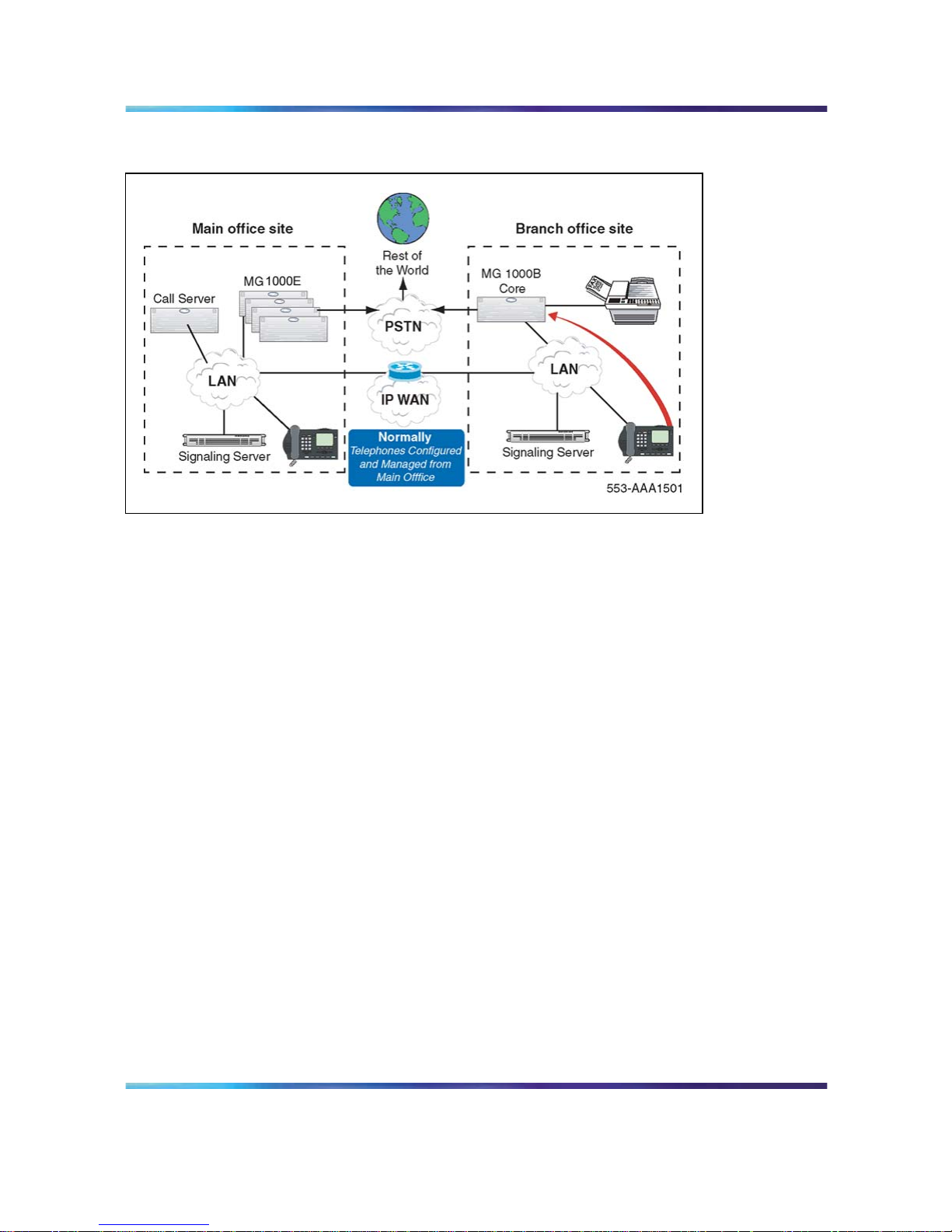
What is Branch Office?
The Branch Office feature extends CS 1000 features from a main office to
one or more remote offices.
The Branch Office feature is implemented on a Media Gateway 1000B
(MG 1000B) platform. The MG 1000B platform includes an MG 1000B
Core connected to an IP PBX at the main office over a LAN or a WAN. This
configuration enables a secondary location to centralize the call processing
of its IP-based communication network. The Call Server at the main office
provides the call processing for the IP Phones in both the main office and
Branch Office locations. The MG 1000B Core provides call processing
functionality to local digital telephones and analog devices. The MG 1000B
Core also provides digital and analog trunk access to the local Public
Switched Telephone Network (PSTN).
The MG 1000B platform connects to the main office over Virtual Trunks on
a LAN/WAN. The main office transmits and controls IP Phone calls and
IP network connections. If the main office fails to function, or if there is
a network outage, the Media Gateway Controller (MGC) card in the MG
1000B Core provides service to the telephones located at the Branch Office
location. This enables the IP Phones to survive the outage between the
Branch Office and the main office.
Currently, MG 1000B Branch Office is small system based; which is still
supported in CS 1000 Release 5.0. In addition, changes are made to
allow large system based branch offices. Branch Office configurations
supported in CS 1000 Release 5.0, and are not changed with the CP PM
(Call Processor Pentium Mobile). Additionally, the CP PM adds the ability
Nortel Communication Server 1000
Branch Office Installation and Commissioning
NN43001-314 01.02 Standard
Release 5.0 20 June 2007
Copyright © 2007, Nortel Networks
.
Page 23

What is Branch Office? 23
for large systems to be supported as a Branch Office. A mixture of pre
CS 1000 Release 5.0 branches are supported with CS 1000 Release 5.0
branches as long as the main office is running the latest software.
The Branch Office feature does not change with the addition of large system
based branches. The Branch Office feature is ported to a large system.
Both small and large systems are supported as either main or branch
offices with only one restriction; the main must be running the highest
release of software.
Support is available for CS 1000 Release 5.0 Branch Office features, as
long as the main office is running the highest release of software. For
example, Branch offices can be either the SSC based MG 1000B (CS 1000
Release 4.5), or the new MGC based MG 1000B (CS 1000 Release 5.0).
With CS 1000 Release 5.0 and the introduction of the new hardware
platforms, the following configurations are supported:
•
Main Office: MGCbased system. Branch Office: MGC based MG
1000B.
•
Main Office: MGC based system. Branch Office: MGC based MG
1000B (large system software stream).
•
Main Office: Large system (1000M or 1000E). Branch Office: MGC
based MG 1000B.
•
Main Office: Large system (1000M or 1000E). Branch Office: MGC
based MG 1000B (large system software stream).
For small Branch Office configurations, the Survivable Remote Gateway
feature can provide the same functionality and benefits as the Branch Office
feature.
You can implement the Branch Office feature as a new hardware
configuration. It can also be created by converting an existing Small System
to an MG 1000B platform (see "Converting a Small System to a Branch
Office" (page 201)). The functionality is the same in both configurations.
The main office can be any one of the CS 1000 systems (see ""Main office
hardware description" (page 28)" More than one Branch Office location
can be associated with a single main office. In addition, one Branch Office
location can be associated with more than one main office.
A Branch Office is designed to work with a main office only if the two offices
use a common dialing plan. Any other configuration is not guaranteed to
work properly.
Figure 1 "Branch Office associated with a CS 1000E main office" (page
24) shows a Branch Office network.
Nortel Communication Server 1000
Branch Office Installation and Commissioning
NN43001-314 01.02 Standard
Release 5.0 20 June 2007
Copyright © 2007, Nortel Networks
.
Page 24
24 Overview
Figure 1
Branch Office associated with a CS 1000E main office
Main Office and Branch Office Migration
All Main Office call servers in CS 1000 Release 5.0 are large system based.
A CS 1000 Small System Main Office is no longer supported. Since all CS
1000 Release 5.0 Small System Controller (SSC) based Main Offices have
been migrated to Call Processor Pentium Mobile (CP-PM) Call Servers, the
Main Office TN (MOTN) Type in a Branch Office will always be set to the
large system MOTN Type.
In a system where the Main Office has been migrated from a SSC to CP-PM
call server, the LD 20 PRT on the branch will not correctly display the MOTN
using the small system TN format until the branch has been migrated or
upgraded. In the case where the branch is SSC based, the LD20 PRT will
remain incorrect until the Branch Office Call Server has been migrated to a
CP-PM call server. In the case where the branch is already a large system
(CP-PII or CP-PIV), then the LD 20 PRT on the branch will remain incorrect
until the branch has been upgraded to CS 1000 Release 5.0.
MG 1000B (MGC) compared to the MG 1000B (SSC)
The MG 1000B with MGC has a number of differences in hardware
capability when compared with Release 4.5 gateways.
The MGC has six Ethernet interfaces for connecting to external networking
equipment. Three are reserved for ELAN connections and three are
reserved for TLAN1 connections. The six external Ethernet interfaces on
the MGC are set to Auto Negotiate mode by default. You can change the
settings for ports 1E, 2T, E and T to 100 Mbps full duplex by using the
Nortel Communication Server 1000
Branch Office Installation and Commissioning
NN43001-314 01.02 Standard
Release 5.0 20 June 2007
Copyright © 2007, Nortel Networks
.
Page 25

MG 1000B (MGC) compared to the MG 1000B (SSC) 25
mgcsetup command. With a properly designed data network, the multiple
ELAN and TLAN interfaces can be used to implement a dual homed
configuration for the MG 1000B with MGC.
Four of these interfaces are accessed by using RJ45 connectors on the
faceplate. Two are reserved for ELAN and two are reserved for TLAN.
Two additional Ethernet connections are available if an Option 11C cabinet
is used. One is reserved for ELAN and one is reserved for TLAN.
For the Option 11C cabinets, to break out the two new 100BaseT Ethernet
connections, you need a new backplane adapter. This adapter replaces
the MDF-to-AUI cable used for the 10BaseT Ethernet connection on the
existing system.
One use for the additional LAN connections is to allow for network
redundancy, also known as dual-homing on the Release 4.5 MG 1000B.
The MGC Ethernet interface failover is accomplished with the embedded
Ethernet switch. The Ethernet interface failover feature requires no special
network configuration to function. The end customer decides if two separate
Layer 2 switches are used to implement the feature to minimize the service
outage. For more information see the Communication Server 1000E:
Installation and Configuration (NN43041-310) NTP.
Also, you can use the broadcast and multi cast rate limiting features of the
embedded Ethernet switch on the MGC to reduce the susceptibility of the
Call Server to broadcast storms and similar network issues, if you directly
cable the Call Server to the MGC.
In addition, certain debug features use the LAN connections (for example,
port mirroring.)
The MGC has two conference loops with thirty units each. The maximum
number of participants in a conference is thirty. On the MG 1000B, the
maximum number of conference loops was four with sixteen units in each
loop. The maximum number of participants in a conference was six.
The MGC has a four-character alphanumeric LED display on the faceplate.
the boot and application software use the display to show diagnostic
information to the technician.
The MGC has a clock reference input/output to support the requirements
of the Digital Enhanced Cordless Telecommunications (DECT) standard.
The DECT product requires a tight clock tolerance between cabinets with
interconnected radio equipment of ±5ppm. To accommodate the tight clock
Nortel Communication Server 1000
Branch Office Installation and Commissioning
NN43001-314 01.02 Standard
Release 5.0 20 June 2007
Copyright © 2007, Nortel Networks
.
Page 26

26 Overview
tolerance, the MGC is equipped with a clock reference input/output. The
clock reference input and output connections and cable detect are provided
through a 15-pin DSUB connector.
MGC Serial Ports
Each MGC installed in a CS 1000B provides the opportunity for 3 remote
SDIs. The maximum number of TTYs does not change. Therefore, after you
configure the maximum TTYs , no additional TTYs are supported.
The MGC has three serial ports SDI0, SDI1, and SDI2.
You can use serial ports for local debugging; or, you can configure the ports
in the MG 1000B Call Server as system terminals in LD 17.
During the initial configuration of the MGC, you must connect to either
SDI0 or SDI1 to access the installation menu. Only SDI0 has full modem
support, as SDI1 and SDI2 have no hardware flow control (limitation of
the three-port cable used).
SDI2 is not available during the MGC bootup; therefore, you cannot use
it to access the installation menus.
Unlike the NTDK20xx SSC card, all SDI ports on the MGC are configured
by using shipped software. No DIP switches are on the MGC for configuring
the baud rate of SDI0.
Single CPU Implications
Single CPU installations do not require dynamic binding of TTY ports to
the active CPU because only one CPU exists. Therefore, single-CPU
installations can use the Call Server TTY ports or the MGC remote TTY
ports.
Dual CPU Implications
MG 1000B uses a terminal server to ensure that serial ports are always
bound to the active CPU. The remote SDIs on the MGC provide similar
functionality. Each MGC provides three SDI ports that you can provision
in the softswitch as TTYs.
Remote TTY provisioning is enhanced over the terminal server model. SDI
port provisioning is performed on the softswitch and does not require local
provisioning at the IPMG.
Terminal Server Support
The remote SDI feature on the MGC eliminates the need for a terminal
server.
Nortel Communication Server 1000
Branch Office Installation and Commissioning
NN43001-314 01.02 Standard
Release 5.0 20 June 2007
Copyright © 2007, Nortel Networks
.
Page 27

MGC Serial Ports 27
MGC serial port default configuration
The default settings for the serial ports are
•
Baud rate = 9600
•
Number of data bits = 8
•
Number of stop bits = 1
•
Parity = none
•
Flow control = none
MGC serial ports configuration change in Overly 17
If you configure the serial ports on an MG 1000B with MGC as SL1 terminals
on the Call Server, then the baud rate, number of data bits, number of stop
bits, parity, and flow control are configured in LD 17.
Any values configured in LD 17 are downloaded to the MGC and override
the default values. The downloaded values are stored on the MGC and
persist over restarts and power outages. When the serial port baud rate is
changed, a system message indicates the change.
CEMux Support
Support of the Option 11C CS 1000M cabinet and chassis CEMux type
cards are additions to the MG 1000B with an MGC with the CP PM. The
list of supported cards is as follows:
Table 2
CEMux Packs and daughter boards supported in MG 1000B with MGC
Pack Daughterboard
IP Expansion CEMux Application
DCHI (NTAK93) non-downloadable DCH
DDCH (NTBK51) downloadable DCH
1.5MB DTI/PRI
(NTAK09)
CC (NTAK20) clock controller (stratum 3/4)
1.5MB TMDI
(NTRB21)
CC (NTAK20) downloadable DCH, clock controller (stratum 3/4)
2.0MB DTI (NTAK
10)
n/a clock controller (stratum 3/4)
2.0MB PRI (NTAK79) n/a clock controller (stratum 3/4), non-downloadable
DCH
DDCH (NTBK51) downloadable DCH2.0MB PRI (NTBK50)
CC (NTAK20 clock controller (stratum 3/4)
MISP (NTBK22) CC (NTAK20) MISP BRI processor, clock controller (stratum 3/4)
SDI_DCH (NTAK02) n/a only DCH is supported
Nortel Communication Server 1000
Branch Office Installation and Commissioning
NN43001-314 01.02 Standard
Release 5.0 20 June 2007
Copyright © 2007, Nortel Networks
.
Page 28

28 Overview
SSTD (NTAK03) not
supported
n/a n/a
Card Option Mail not
supported
n/a n/a
Standard Option 11C minimum vintages apply to all packs and daughter
boards.
Attempts to install unsupported CEMux packs or to configure an
unsupported application are blocked.
Support of CEMux requires CS 1000 Release 5.0 Softswitch software and
a Media Gateway Controller Card (MGC). It is supported by all MG 1000B
systems.
Features supported by Option 11C SIPE related to CEMux are supported in
MG 1000B, which includes support for nB+D by having single D-Channel
support trunk packs in separate MG1000Bs.
The TMDI D-Channel ISM used on small systems IS NOT included for the
CS 1000B. D-Channels configured or removed for TMDI cards increment
the existing large system software based DCH ISM. The maximum number
of D-Channels, which is 255, supported with CS 1000B in CS 1000 Release
5.0, matches that of the CS 1000M large systems.
For BRI, you must provision the MISP and the SILC/UILC in the same
IPMG. This is the only supported configuration.
Clock References
With CEMux support, you can configure digital trunks and clock controller
configuration in the IPMG. Each IPMG that contains a digital trunk card
requires a clock controller on that shelf. You cannot use Clock references
across IPMGs, and you can configure only one clock controller per shelf..
Main office hardware description
The main office must be one of the following systems:
•
CS 1000E
•
CS 1000M Cabinet
•
CS 1000M Chassis
•
CS 1000M HG
•
CS 1000M SG
•
CS 1000M MG
Nortel Communication Server 1000
Branch Office Installation and Commissioning
NN43001-314 01.02 Standard
Release 5.0 20 June 2007
Copyright © 2007, Nortel Networks
.
Page 29

MG 1000B platform hardware description 29
The diagrams throughout this document show a CS 1000E main office. All
of the systems appearing in the list perform identical main office functions
as far as the Branch Office feature is concerned.
MG 1000B platform hardware description
The MG 1000B system has been enhanced for CS 1000 Release 5.0 Branch
Office. The CP-PM Call Server and MGC replace the SSC (Motorola) used
in the Release 4.0/4.5 MG 1000B. The Voice Gateway Media Card is still
supported however, the DSPs are also available on the MGC.
Two new DSP Daughterboards are included in the CS 1000 portfolio of
products. The daughterboards are available in two different sizes, a 32-port
daughterboard and a 96-port daughterboard. These daughterboards are
located on the Media Gateway Controller (MGC) card to provide DSP
resources for connecting IP and TDM devices. These daughterboards
eliminate the need to instal the Voice Gateway Media Cards within the CS
1000E Media Gateways (MG 1000B) chassis, to save slots and reduce cost
over the current Voice Gateway Media Card solution. The addition of the
DSP Daughterboards into a MG 1000B system does not limit the use of
Voice Gateway Media Cards (either Pentium or Strong-Arm versions), either
for DSP-only functionality or for the full IP Line application within the same
system. The MGC is used only in the Media Gateway chassis or Option
11C-style cabinets. Froma functional perspective, the DSP Daughterboards
behave in a similar manner as the current Voice Gateway (VGW) application
on the Voice Gateway Media Card.
Support exists for four configurations:
•
a system with no DSP DBs or Voice Gateway Media Card (A pure TDM
system, single media gateway).
•
a system with only Voice Gateway Media Cards
• a system with only DSP DBs
— a 32-port daughterboard in daughterboard position 1
— a 32-port daughterboard in daughterboard position 2
— A 32-port daughterboard in daughterboard position 1 and a 32-port
daughterboard in daughterboard position 2
— a 96-port daughterboard in daughterboard position 1
— a 96-port daughterboard in daughterboard position 1 and a 32-port
daughterboard in daughterboard position 2
•
a system with DSP DBs (all of the position combinations described in c)
and Voice Gateway Media Cards.
The basic hardware of an MG 1000B platform includes the MG 1000B Core
and the Signaling Server.
Nortel Communication Server 1000
Branch Office Installation and Commissioning
NN43001-314 01.02 Standard
Release 5.0 20 June 2007
Copyright © 2007, Nortel Networks
.
Page 30
30 Overview
Figure 2
CS 1000 Release 5.0 MG 1000B System
CS 1000 Release 5.0 continues to support the existing Branch Office
configuration that uses the SSC processor, but Nortel no longer offers sales
of the SSC based Branch Office.
CS 1000 Release 5.0 provides various hardware versions of the Signaling
Server, the existing ISP1100 signaling servers, or the new CP-PM Signaling
Server.
With CS 1000 Release 5.0 Branch Office, the hardware configuration
includes a CP-PM call processor card with the MGC, as well as a CP-PM
Signalling Server. If the CP-PM Signalling Server configuration cannot be
used, the option exists to use the Signaling Server on COTS.
The MG 1000B Core and MG 1000B Expander can connect to either a
LAN or a WAN.
An MG 1000B platform can be a new hardware configuration. It can also
be a Small System platform converted to an MG 1000B platform. In the
latter case, the cabinet or chassis performs the same functionality as the
Nortel Communication Server 1000
Branch Office Installation and Commissioning
NN43001-314 01.02 Standard
Release 5.0 20 June 2007
Copyright © 2007, Nortel Networks
.
Page 31

MG 1000B platform hardware description 31
MG 1000B Core, and the optional chassis expander performs the same
functionality as the MG 1000B Expander. Refer to "Converting a Small
System to a Branch Office" (page 201) for more information.
After conversion to an MG 1000B platform, the Small System cabinet or
chassis is referred to as an "MG 1000B Cabinet" or "MG 1000B Chassis",
as applicable. The optional chassis expander is referred to as the "MG
1000B Chassis Expander".
Throughout this document, the term "MG 1000B Core" can refer to an MG
1000B Cabinet or MG 1000B Chassis for a converted Small System, unless
otherwise indicated. Likewise, the term "MG 1000B Expander" can refer to
an MG 1000B Chassis Expander.
MG 1000B Core
The MG 1000B Core provides access to the local PSTN for users in the
Branch Office. It also provides support for digital telephones and analog
devices, such as fax machines and analog (500/2500-type) telephones
in the Branch Office.
Where required, the MG 1000B Core is connected by copper wire to the MG
1000B Expander for added capacity.
The MG 1000B Core must contain a CP-PM Call Server. The CP-PM Call
Server provides telephony services to elements at the Branch Office, such
as digital telephones, analog devices, digital trunks, and analog trunks.
It also provides call processing services to IP Phones when the phones
are registered to the MG 1000B Core (Local Mode). The MG 1000B Core
provides a dedicated slot (slot 0) for the CP PM. The software feature set on
the CP PM can differ from that of the Call Server at the main office.
The 10/100BaseT connection for the Embedded Local Area Network
(ELAN) and Telephony Local Area Network (TLAN) subnets, where the MG
1000B Core exists, is on the back of the MG 1000B Core.
Figure 3 "MG 1000B Core/MG 1000B Expander" (page 32) shows an MG
1000B Core/MG 1000B Expander.
Nortel Communication Server 1000
Branch Office Installation and Commissioning
NN43001-314 01.02 Standard
Release 5.0 20 June 2007
Copyright © 2007, Nortel Networks
.
Page 32

32 Overview
Figure 3
MG 1000B Core/MG 1000B Expander
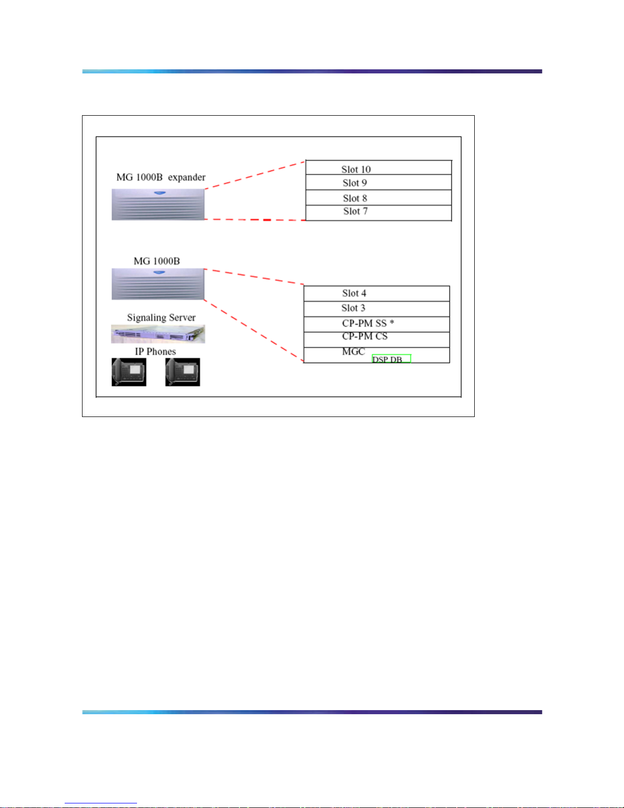
MG 1000B Chassis
CEMux packs are supported in card positions 1 to 4 of an MG 1000B
chassis. They are not supported in the MG 1000B expander chassis, similar
to what is the support in the Option 11C SIPE system.
Card slots
Table 3 "Card slots for MG 1000B Core and MG 1000B Expander" (page 32)
shows the card slot assignments for all configurations of the MG 1000B Core
and MG 1000B Expander (discussed on "MG 1000B Expander" (page 33)).
Table 3
Card slots for MG 1000B Core and MG 1000B Expander
MG 1000B Core MG 1000B
Expander
MG 1000B
Configuration
Total
Slot #
for
Slot # for
48-port
Usable TotalUsable
Nortel Communication Server 1000
Branch Office Installation and Commissioning
NN43001-314 01.02 Standard
Release 5.0 20 June 2007
Copyright © 2007, Nortel Networks
.
Page 33

MG 1000B platform hardware description 33
slots MGC DLC slot #s slotsslot #s
MG 1000B Core
50
Not used
1-4 4 7-10
MG 1000B Cabinet
11 0
Not used
1-10
(see
Note 1)
N/A N/A
MG 1000B Chassis
5
0
4 (see
Note 2)
1-3 4 7-10
(see
Note 1)
For converted Small Systems only, the Meridian Mail card must be installed in slot 10 if Meridian
Mail is to be supported.
If the 48-port Digital Line Card (DLC) is not used, slot 4 must remain unused. However, it can be
covered by a double-slot card, such as an ITG-P card, inserted in slot 3.
In Table 3 "Card slots for MG 1000B Core and MG 1000B Expander" (page
32), the term "usable" denotes those card slots which are not reserved for,
or dedicated to, a specific card type. The following circuit cards can be
installed in any "usable" slot:
•
Media Cards
•
Digital Trunk cards
•
Analog Trunk cards
•
Analog Line cards
•
Digital Line cards
•
Nortel Integrated Recorded Announcer card
•
Nortel Integrated Conference Bridge card
•
cards to support CallPilot Mini or CallPilot 201i
The legacy 24-port ITG-P card, when upgraded to IP Line 4.5 software,
provides the same service as the Media Card. In this document, unless
otherwise noted, the ITG-P card can be substituted for the Media Card.
The Media Cards act exclusively as Voice Gateway Media Cards on the
MG 1000B platform.
MG 1000B Expander
The MG 1000B Expander can be used with all MG 1000B platform
configurations except the MG 1000B Cabinet. The MG 1000B Expander is
identical to the MG 1000B Core with the following exceptions:
•
Digital trunk cards are not supported in the MG 1000B Expander.
Nortel Communication Server 1000
Branch Office Installation and Commissioning
NN43001-314 01.02 Standard
Release 5.0 20 June 2007
Copyright © 2007, Nortel Networks
.
Page 34

34 Overview
•
The MG 1000B Expander is connected to the MG 1000B Core with
copper wire. Therefore, the back of the MG 1000B Expander does not
have an Ethernet port.
Figure 3 "MG 1000B Core/MG 1000B Expander" (page 32) shows the MG
1000B Expander. Table 3 "Card slots for MG 1000B Core and MG 1000B
Expander" (page 32) gives the card slots for the MG 1000B Expander.
Signaling Server
The Signaling Server is required for the Branch Office feature. It provides
the following functions:
•
IP Peer Networking, incorporating:
— SIP and H.323 Gateways
— Network Routing Service (NRS), consisting of:
– SIP Redirect Server
– H.323 Gatekeeper
– Network Connection Service (NCS)
•
IP Phone registration to the IP Phone Terminal Proxy Server (TPS)
during Local Mode for survivability
•
Web server for Element Manager and NRS Manager
A second Signaling Server can be used to provide redundancy in the case
of a failure in the other Signaling Server at the Branch Office. The NRS
must reside on the Leader Signaling Server.
A network requires one NRS. However, Nortel recommends that an
Alternate NRS, and in some cases at least one Failsafe NRS, be configured
in the network. In a Branch Office network, configuring a Primary or
Alternate NRS at a Branch Office location is not appropriate due to possible
network outages. For maximum coverage, Nortel recommends that a
Failsafe NRS be configured at each Branch Office location that is not
otherwise configured with a Primary or Alternate NRS.
In a SIP-enabled system, the Signaling Server supports only en bloc
signaling.
In an H.323-enabled system, the Signaling Server supports both en bloc
and overlap signaling. En bloc signaling is standard. If overlap signaling is
to be used, Nortel highly recommends that it be installed and enabled on all
Signaling Servers in the network. Failure to do so results in delays in call
completion due to overlap to en-bloc conversion.
Nortel Communication Server 1000
Branch Office Installation and Commissioning
NN43001-314 01.02 Standard
Release 5.0 20 June 2007
Copyright © 2007, Nortel Networks
.
Page 35

MG 1000B platform hardware description 35
For more information on the Signaling Server, refer to Signaling Server
Installation and Commissioning (NN43001-312). For more information on
SIP, H.323, and overlap signaling, refer to IP Peer Networking Installation
and Commissioning (NN43001-313) .
The NCS is required to provide the Main Office Node IP’s actual status. The
redirection procedure cannot be performed without the NCS. Interaction
with the NCS Branch Office requires the same H.323 ID to be configured for
each Branch Office node element (MGC). This H.323 ID exists in the NCS
(NRS H.323 Gatekeeper) Database. If there is no H.323 ID in the NCS
database, the NCS ignores the request for translation from the Branch user
ID (BUID) into associated Main office node IP. For more information on the
NCS, refer to "MG 1000B Core interoperability" (page 176) and "Adding the
Branch Office endpoints to the NRS database" (page 260).
Network Routing Service (NRS)
The NRS application provides network-based routing, combining the
following into a single application:
•
H.323 Gatekeeper — provides central dialing plan management and
routing for H.323-based endpoints and gateways.
•
SIP Redirect Server — provides central dialing plan management and
routing for SIP-based endpoints and gateways.
• NRS Database — stores the central dialing plan in XML format for both
the SIP Redirect Server and the H.323 Gatekeeper. The SIP Redirect
Server and the H.323 Gatekeeper accesses this common endpoint and
gateway database.
•
Network Connect Server (NCS) — used only for Media Gateway
1000B (MG 1000B), SRG, Geographic Redundancy and Virtual Office
solutions. The NCS allows the Line TPS (LTPS) to query the NRS using
the UNIStim protocol.
•
NRS Manager web interface — the NRS provides its own web interface
to configure the SIP Redirect Server, the H.323 Gatekeeper, and the
NCS.
The NRS application provides routing services to both H.323 and
SIP-compliant devices. The H.323 Gatekeeper can be configured to support
H.323 routing services, while the SIP Redirect Server can be configured to
support SIP routing services. The H.323 Gatekeeper and the SIP Redirect
Server can reside on the same Signaling Server.
Each system in an IP Peer network must register to the NRS. The NRS
software identifies the IP addresses of systems based on the network-wide
numbering plan. NRS registration eliminates the need for manual
configuration of IP addresses and numbering plan information at every site.
Nortel Communication Server 1000
Branch Office Installation and Commissioning
NN43001-314 01.02 Standard
Release 5.0 20 June 2007
Copyright © 2007, Nortel Networks
.
Page 36

36 Overview
When configuring the NRS it is necessary to enable the NCS. Ensure the
check box "Network Connection Server enabled" is checked in the NRS
configuration window of CS 1000 Element Manager.
For information on configuring the NRS, refer to IP Peer Networking
Installation and Commissioning (NN43001-313) .
Telephones
The Branch Office feature supports the following telephones:
•
Nortel IP Phone 2001
•
Nortel IP Phone 2002
•
Nortel IP Phone 2004
•
Nortel IP Phone 2007 — configured as IP Phone 2004. In CS 1000
Release 5.0, IP phone 2007 can be configured as itself.
• IP Phone Key Expansion Module (KEM)
•
WLAN Handset 2210/2211/2212
•
Analog (500-2500 type) and digital telephones
• Nortel IP Softphone 2050
•
Nortel Mobile Voice Client 2050
•
IP Phone 1120E
• IP Phone 1140E
•
IP Phone 1150E
Naming of existing IP Phone TN Types is changed to be consistent with
latest IP Phone naming convention. Below is a table of Rls 4.5 and Rls 5.0
IP Phone TN Types. You can no longer use old names in the overlays, so
when the system administrator tries to use any of the old names, new SCH
message is printed.
Table 4
New IP Phone TN type naming convention
IP Phone Model Name CS 1000 Release 4.5 TN
Type
CS 1000 Release 5.0 TN Type
IP Phone 2001 i2001 2001P2
IP Phone 2002 Phase I i2002 2002P1
IP Phone 2002 Phase II i2002 2002P2
IP Phone 2004 Phase 0/1 i2004 2004P1
IP Phone 2004 Phase II i2004 2004P2
Nortel Communication Server 1000
Branch Office Installation and Commissioning
NN43001-314 01.02 Standard
Release 5.0 20 June 2007
Copyright © 2007, Nortel Networks
.
Page 37

MG 1000B platform hardware description 37
IP Audio Conference Phone
2033
i2001
2033
IP Softphone 2050 i2050 2050PC
Mobile Voice Client 2050 i2050 2050MC
WLAN Handset 2210 i2004
2210
WLAN Handset 2211 i2004
2211
WLAN Handset 2212 i2004
2212
IP Phone 1110 i2001
1110
IP Phone 2007 i2004
2007
IP Phone 1120E i2004
1120
IP Phone 1140E i2004
1140
IP Phone 1150E iPACD
1150
Throughout this document, the telephones in this list are referred to
collectively as "IP Phones." IP Phones in the Branch Office are referred
to as "Branch Users."
In an H.323-enabled system, the IP Phones are provisioned in the Branch
Office using Set-Based Installation, Command Line Interface (CLI) overlays,
or Telephony Manager 3.1 (TM 3.1).
Firmware download
The Enhanced UniStim Firmware Download for IP Phones feature provided
an improved method of delivering new firmware to Nortel IP Phones.
For further information on the Enhanced UniStim Firmware Download for IP
Phones feature, refer to IP Line Fundamentals (NN43100-500).
Voice Gateway Media Card
For CS 1000 Release 5.0, the new Media Card 32S (MC32S) fully replaces
the functionality of the current VGMV pack NTVQ01BB. You can use the
new pack in both large and small systems, and anywhere you can use
the current NTVQ01BB pack. The MC32S also adds SRTP security. For
an MGC-based MG 1000B, the sets are configured in four-field format.
For additional information, see theIP Line: Description and Information
(NN43100-500)NTP or theCircuit Card: Description and Installation
(NN43001-311)NTP.
The Media Card acts as a Voice Gateway Media Card, providing a pool of
Digital Signal Processor (DSP) ports for media transcoding between IP
voice packets and circuit-switched resources. The card comes equipped
with DSP modules. Each call between an IP Phone and an analog
Nortel Communication Server 1000
Branch Office Installation and Commissioning
NN43001-314 01.02 Standard
Release 5.0 20 June 2007
Copyright © 2007, Nortel Networks
.
Page 38

38 Overview
(500/2500-type) or digital telephone or the PSTN uses one DSP port. Calls
between two IP Phones do not require any DSP ports, as there is no need
for IP-to-circuit-switched transcoding.
Media Cards provide echo cancellation, compression, and decompression
of voice streams.For more information about DSP resources residing on the
MGC that are configured with DSP Daughterboards, see the CS 1000E
Installation and Configuration NTP.
The ITG-P card uses two card slots in the MG 1000B Core, whereas the
Media Card uses one card slot.
Analog or digital trunk cards
All analog and digital trunk interfaces supported on CS 1000 systems are
also supported by the Branch Office feature. Analog and digital trunk cards
interface with the PSTN. For information on trunk cards, refer to Circuit Card
Reference(NN43001-311).
Analog or digital line cards
Analog (500/2500-type) or digital telephones and devices are supported by
the Branch Office feature. For information about line cards, refer to Circuit
Card Reference(NN43001-311).
When additional digital and analog (500/2500-type) telephones are located
in the Branch Office, additional DSP resources are required. Refer to
"Media Card DSP capacity" (page 47).
Lineside cards
MG 1000B supports the following lineside cards:
• NTD514 line side T1
•
NTD534 line side E1
For further information about T1/E1 lineside cards, refer to Circuit Card
Reference(NN43001-311).
MG 1000B with MGC Data Networking
MG 1000B with MGC shelves communicates with the Call Server using
the built-in 100BaseT Ethernet Interface on the MGC. Three Ethernet
ports on the MGC can be used to connect to the ELAN, two for use by
the dual-homing feature and one for a direct connection to a Call Server
platform.
Nortel Communication Server 1000
Branch Office Installation and Commissioning
NN43001-314 01.02 Standard
Release 5.0 20 June 2007
Copyright © 2007, Nortel Networks
.
Page 39

MG 1000B with MGC Data Networking 39
You can connect the MGC to a Layer 2 switch to handle signaling between
the Call Server and the MG 1000Bs. If two of the MGC ELAN ports connect
to separate Layer 2 switches, the MG 1000B can remain operational if one
of the Layer 2 switches fails.
MG 1000B shelves must have a data network connectivity to the ELAN
port of the Call Server. The design of the data networking configuration is
outside the scope of this document. The engineering of the data network is
documented in the Data Networking for Voice over IP (NN43001-260) NTP.
The MG 1000B with MGC by default supports Auto Negotiate mode on
the embedded Ethernet interfaces; you must configure the networking
equipment to which they connect as Auto Negotiate. If the MGC Ethernet
ports do not auto-negotiate to 100 Mb Full Duplex, an alarm occurs, as
issues can arise if the speed is not 100 Mb, and if the duplex is only half. A
CLI command is also available on the MGC to turn off auto-negotiation for
the embedded Ethernet interfaces, which configures the interfaces to 100
MB Full Duplex. No other speed or duplex options are availableon the MGC.
CS 1000B/MG 1000B with MGC - Data Network Topology illustrates a
typical robust network topology.
Figure 4
CS 1000B and MG 1000B with MGC - Data Network Topology
Nortel Communication Server 1000
Branch Office Installation and Commissioning
NN43001-314 01.02 Standard
Release 5.0 20 June 2007
Copyright © 2007, Nortel Networks
.
Page 40

40 Overview
MGC Network Connections
In the following diagrams, two connections are shown to the external data
equipment for the dual-homing feature, distributed and nondistributed.
Nondistributed means that both Ethernet ports (TLAN or ELAN) of the
dual-homing feature connect to a single Layer 2 switch, thus providing a
single point of failure if that switch goes out of service.
Distributed means that the two Ethernet ports (TLAN or ELAN) of the
dual-homing feature connect to separate Layer 2 switches, to provide
another level of redundancy and no single point of failure with a Layer 2
switch. Nortel recommends distributed connections; support is available for
nondistributed connections if the cost of the additional data networking
equipment is an issue.
The CE and CT ports on the MGC are the only embedded Ethernet ports
that allow a direct connection to another device, and the only card supported
for this direct connection is the CP-PM Call Server. For a cascading
configuration, you can use the 1E and 1T ports can be used to connect
to another MGC card.
The figure below shows the supported configuration for a single server
configuration without redundant network configurations. This is the standard
configuration of a cost effective single server configuration. A single server
supports multiple MGCs using external networking equipment.
Figure 5
Single server port network connections (no dual-homing)
Nortel Communication Server 1000
Branch Office Installation and Commissioning
NN43001-314 01.02 Standard
Release 5.0 20 June 2007
Copyright © 2007, Nortel Networks
.
Page 41

MG 1000B with MGC Data Networking 41
The following figure illustrates a typical network configuration that supports
dual homing of both the ELAN and TLAN. With this configuration, however,
a single Layer 2 switch remains a single point of failure.
Figure 6
Single server port network connections (dual-homing - non distributed)
The following figure illustrates a typical network configuration that supports
dual homing of both the ELAN and TLAN. Multiple Layer 2 switches ensure
there isn’t a single point of failure. Nortel recommends this configuration for
the highest reliability in a single CPU Call Server configuration. You must
partition the layer 2 switch into separate VLANs to keep the ELAN and
TLAN traffic on separate subnets
Nortel Communication Server 1000
Branch Office Installation and Commissioning
NN43001-314 01.02 Standard
Release 5.0 20 June 2007
Copyright © 2007, Nortel Networks
.
Page 42

42 Overview
Figure 7
Single server port network connections (dual-homing - distributed)
The following figure illustrates a typical network configuration for a dual
CPU Call Server configuration that supports dual homing of both the ELAN
and TLAN. Multiple Layer 2 switches ensure there isn’t a single point of
failure. Nortel recommends this configuration in a dual CPU Call Server
configuration. In this configuration, the CP-PM call server benefits from the
dual homing feature of the MGC, and remains connected to the network,
even if one of the layer 2 ELAN switches fails, avoiding a CPU switchover
due to a network outage.
Nortel Communication Server 1000
Branch Office Installation and Commissioning
NN43001-314 01.02 Standard
Release 5.0 20 June 2007
Copyright © 2007, Nortel Networks
.
Page 43

MG 1000B with MGC Data Networking 43
Figure 8
Multi server port network configuration (dual-homing - distributed)
Cascading can occur for the MGC network connections for up to a maximum
of 2 cabinets. You can directly cable the MGCs , without the need for
external Layer 2 switches. Nortel recommends this type of configuration for
a pure TDM solution.
Figure 9
Single server port network connections - cascading
Nortel Communication Server 1000
Branch Office Installation and Commissioning
NN43001-314 01.02 Standard
Release 5.0 20 June 2007
Copyright © 2007, Nortel Networks
.
Page 44

44 Overview
Multi Server (CP-P4) Port Network Configuration (Dual-homing Distributed), shows a configuration with a Call Server platform that does not
reside in a MG 1000B cabinet and chassis; therefore no direct connection
exists to the MGC. The CP-P4 call server does not use the MGC dual
homing feature to increase the system reliability
Figure 10
Multi server (CP-P4) port network configuration (dual-homing - distributed)
MG 1000B platform configuration overview
In each MG 1000B Core, one CP PM and MGC is required. The three
remaining slots (nine in an MG 1000B Cabinet) can contain analog line
cards, analog trunk cards, digital line cards, or digital trunk cards. Refer to
Table 3 "Card slots for MG 1000B Core and MG 1000B Expander" (page
32) for a summary of the allowable card slots.
Each MG 1000B Core with a digital trunk card must have a clock controller.
See Circuit Card Reference(NN43001-311)
For further information on line side T1 and line side E1 cards, refer to
There are two configurations for the MG 1000B platform:
•
without an MG 1000B Expander
•
with an MG 1000B Expander
Nortel Communication Server 1000
Branch Office Installation and Commissioning
NN43001-314 01.02 Standard
Release 5.0 20 June 2007
Copyright © 2007, Nortel Networks
.
Page 45

MG 1000B platform configuration overview 45
MG 1000B platform without an MG 1000B Expander
Figure 11 "MG 1000B platform without MG 1000B Expander" (page 45)
shows an MG 1000B platform configured without an MG 1000B Expander.
This configuration has a single MG 1000B Core.
Figure 11
MG 1000B platform without MG 1000B Expander
This MG 1000B platform configuration requires at least one Voice Gateway
Media Card. The additional slots can be used for any combination of the
following:
•
trunk card
•
analog or digital line card
•
second Media Card
•
Nortel Integrated Conference Bridge card
•
Nortel Integrated Recorded Announcer card
•
cards to support CallPilot Mini or CallPilot 201i
•
Meridian Mail card (for converted Small Systems only)
Nortel Communication Server 1000
Branch Office Installation and Commissioning
NN43001-314 01.02 Standard
Release 5.0 20 June 2007
Copyright © 2007, Nortel Networks
.
Page 46

46 Overview
For more information on the Voice Gateway Media Card configuration,
refer to IP Line Fundamentals (NN43100-500). For more information
on Integrated Conference Bridge, refer to Integrated Conference Bridge
Service Implementation Guide (NN43001-558).
MG 1000B platform with an MG 1000B Expander
Figure 12 "MG 1000B platform with MG 1000B Expander" (page 46) shows
an MG 1000B platform configured with an MG 1000B Expander. With the
addition of an MG 1000B Expander, you have additional usable slots. There
must be at least one Media Card (8- or 32-port cards with IP Line 4.5) for
the MG 1000B Core. If more than one Media Card is used, the cards may
all be located in one chassis or distributed among them.
The MG 1000B Expander does not support digital trunks.
Figure 12
MG 1000B platform with MG 1000B Expander
Nortel Communication Server 1000
Branch Office Installation and Commissioning
NN43001-314 01.02 Standard
Release 5.0 20 June 2007
Copyright © 2007, Nortel Networks
.
Page 47

Software requirements 47
Capacity
Each CS 1000 main office can support up to 255 branch offices. Each
Branch Office supports up to 400 IP Phone users. However, since all IP
Phones register with the main office, the governing factor is the maximum
number of IP Phones that can be supported at the main office. This
means the total number of IP Phones in all offices can be no greater
than the capacity of the main office, as determined using Communication
Server 1000E Planning and Engineering (NN43041-220), Communication
Server 1000M and Meridian 1 Large System Planning and Engineering
(NN43021-220),orCommunication Server 1000M and Meridian 1 Small
System Planning and Engineering (NN43011-220).
The configuration of an MG 1000B platform depends on:
•
the number of line and trunk cards being provisioned
•
the number of Media Cards required to provide a sufficient number of
DSP channels
Media Card DSP capacity
The number of DSP ports to provision depends on the trunk-to-telephone
ratio. A rule-of-thumb is to have the number of ports greater than or
equal to the number of trunks configured. See Communication Server
1000S: Planning and Engineering (NN43031-220) (or Communication
Server 1000M and Meridian 1 Small System Planning and Engineering
(NN43011-220) for converted Small Systems) for more information.
If digital telephones and analog (500/2500-type) telephones are equipped at
the Branch Office, additional DSP ports are needed for digital-to-IP Phone
and analog-to-IP Phone connections. The number of additional DSP ports
must be equal to or greater than the expected number of simultaneous
connections of these types. The user can engineer fewer DSP ports
depending on their desired blocking ratio.
Software requirements
This section describes the relative software versions required in the
main office and Branch Office locations. The actual software packaging
requirements are given in "Main office requirements" (page 192) and
"Branch Office requirements" (page 193).
Main and Branch Office running the same release
Normally, the main office and associated Branch Office run the same
software release.
However, a Branch Office location can be running an earlier software
release than that running at the main office. This situation is discussed in
the next section.
Nortel Communication Server 1000
Branch Office Installation and Commissioning
NN43001-314 01.02 Standard
Release 5.0 20 June 2007
Copyright © 2007, Nortel Networks
.
Page 48

48 Overview
Main and Branch Office running different releases
The Main Office Call Server and the Branch Office can have different
software releases, as long as the Main Office runs at the highest release.
With the introduction of CS 1000 Release 5.0 program, Nortel’s policy
will be if the main office Call Server is running CS 1000 Release 5.0, the
Branch Office can run on CS 1000 Release 5.0, CS 1000 Release 4.5, or
CS 1000 Release 4.0.
Some functionality found in CS 1000 Release 5.0 is not available in earlier
releases. For example, CS 1000 Release 4.0 does not support Active Call
Failover
It is recommended that the software release on the Branch Office always
match the software release on the main office. In addition, it is possible to
have branch offices running different software releases.
Take into consideration planning your upgrade with this mixed software
policy. Customers must ensure their Branch Offices are at CS 1000 Release
4.5 or CS 1000 Release 4.0 prior to upgrading the main office to CS 1000
Release 5.0 to ensure a supported configuration during the upgrade period.
Both the Call Server and Signaling Server in the main office must run the
same release of software.
If the NRS at the Branch Office is also the Alternate NRS in the network,
then both it and the Primary NRS must be running the same software
release.
This capability is required to support customers who are currently running a
network of CS 1000 Release 4.0 or CS 1000 Release 4.5 branch offices
with a CS 1000 Release 5.0 main office, and who want to add one Branch
Office running CS 1000 Release 5.0. By allowing this mixed-software
operation, customers do not have to upgrade their entire network from a
CS 1000 Release 4.0 or CS 1000 Release 4.5 to CS 1000 Release 5.0 at
the same time.
If the Branch Office is running CS 1000 Release 4.0 or CS 1000 Release
4.5, you do not have to upgrade the Branch Office to CS 1000 Release 5.0.
Indefinite operation with a mixed-software configuration of CS 1000 Release
4.0 and CS 1000 Release 4.5 branch offices and a CS 1000 Release 5.0
main office is supported.
For information on upgrading software, refer to "Upgrading to CS 1000
Release 5.0" (page 207).
Nortel Communication Server 1000
Branch Office Installation and Commissioning
NN43001-314 01.02 Standard
Release 5.0 20 June 2007
Copyright © 2007, Nortel Networks
.
Page 49

Software requirements 49
Features in mixed-software configurations
Feature operation of IP Phone users in Normal Mode is the feature set on
the main office. IP Phone users in Local Mode use the feature set on the
Branch Office. Users of analog and digital devices always use the feature
set on the Branch Office.
However, be advised that if the Branch Office is running a lower release of
software than the main office, features involving interaction between the
main office and the Branch Office will not function for the Branch Office IP
Phone users. For example, if the main office is on CS 1000 Release 4.5 and
the Branch Office is on CS 1000 Release 4.0 or Succession 3.0, the Active
Call Failover feature and the Enhanced UNIStim Firmware download feature
will not operate for the Branch Office IP Phone users since these features
are not supported on earlier releases. In this case, the Branch Office would
need to be upgraded to CS 1000 Release 4.5 to support these features.
Adding a Branch Office to an existing network
For customers wanting to add a Branch Office to their existing network, with
the introduction of CS 1000 Release 5.0, customers are to order a Branch
Office running CS 1000 Release 4.0 if their main office is running CS 1000
Release 4.0. They are also permitted to order a Branch Office running
CS 1000 Release 4.5 if their main office is running CS 1000 Release 4.5.
However, they will no longer be permitted to order a Branch Office running
on Succession 3.0. This differs from the introduction of CS 1000 Release
4.5, customers which allowed customers to order a Branch Office running
Succession 3.0 software only if their main office is running Succession 3.0
software. They were also permitted to order a Branch Office running on
Succession 3.0 if the main office was running Succession 3.0.
IP Phone firmware
When you add a new CS 1000 Release 5.0 Branch Office to a network that
has CS 1000 Release 4.0 or CS 1000 Release 4.5 branch offices, you must
choose whether to upgrade IP Phone firmware for existing branch offices.
You can choose not to upgrade the IP Phone firmware at the existing branch
offices only if the IP Phones in those branch offices are running at least the
minimum version of firmware as specified in "Telephones" (page 36).
If you choose to upgrade only the IP Phone firmware, you must upgrade the
IP Phone firmware at the existing branch offices first. The main office may
not require an IP Phone firmware upgrade, depending on its current version.
With the introduction of Enhanced UNIStim Firmware Download feature
for Release 4.5, IP Phone firmware at the Branch Office is automatically
downloaded from the main office.
Nortel Communication Server 1000
Branch Office Installation and Commissioning
NN43001-314 01.02 Standard
Release 5.0 20 June 2007
Copyright © 2007, Nortel Networks
.
Page 50

50 Overview
Refer to "Firmware downloads" (page 345) for more information on
upgrading firmware for the IP Phone 2001, IP Phone 2002, IP Phone 2004,
and IP Phone 2007.
Package Combinations
The MG 1000B with MGC requires existing packages 402 SOFTSWITCH
and 403 IPMG that were introduced in Rls 4.0.
Package combinations supported using the Rls 4.5 MG 1000B are
supported by the MG 1000B with MGC.
For MG 1000B with MGCs, the Branch Office package 390 and IPMG
package 403 are required.
GRPRIM (Geographic Redundancy Primary CS Package) and GRSEC
(Geographic Redundancy Secondary CS Package) are restricted on Branch
Office environment.
Supported applications
The Branch Office feature supports TM 3.01, Nortel Integrated Conference
Bridge, Nortel Integrated Recorded Announcer, CallPilot Mini, and CallPilot
201i at the Branch Office location.
Survivability
The Branch Office provides survivability against WAN failure, Main Office
Call Server failure, or Signaling Server failure. Survivability is also provided
during the Main Office upgrade, including Signaling Server and Call Server
upgrade. A Call Server and Signaling Server are required in the Branch
Office with CS 1000 Release 5.0.
The Branch Office supports Geographic Redundancy as a Main Office
feature. For further information on Geographic Redundancy, see System
Redundancy (NN43001-507).
Branch Office supports the Network Wide Redundancy Phase II feature,
which is supported by the MG 1000B to provide survivability to IP telephones
normally registered with a CS 2100 and CS 1000. For additional information
see theSystem Redundancy (NN43001-507)NTP.
If a LAN/WAN fails, the MG 1000B IP Phones lose communication with the
main office TPS. This causes the IP Phones to reset and register with the
MG 1000B TPS and the MG 1000B Call Server. The IP Phones operate in
Local Mode, and receive call processing services from the call server. In
Local Mode, the MG 1000B TPS tries to communicate with the main office
TPS at regular intervals. Once communication is established with the main
office TPS, the MG 1000B IP Phones are redirected to the main office.
Nortel Communication Server 1000
Branch Office Installation and Commissioning
NN43001-314 01.02 Standard
Release 5.0 20 June 2007
Copyright © 2007, Nortel Networks
.
Page 51

Survivability 51
If the main office Call Server fails and call processing services are provided
by an alternate Call Server, the MG 1000B IP Phones register with the
alternate Call Server and receive call processing services from it. If no
alternate Call Server is available, the MG 1000B IP Phones stay registered
with the main office TPS for ten minutes. At the end of the ten minutes, the
IP Phones reset and register with the call server. If a key on a particular IP
Phone is pressed before the end of the ten minutes, that telephone resets
and registers with the call server immediately after the key is pressed.
When the main office Signaling Server fails and an Alternate Signaling
Server is available, the MG 1000B IP Phones reset and reregisters with the
main office Call Server through the Alternate Signaling Server, and continue
to receive call processing services from the main office Call Server. If no
Alternate Signaling Server is available, the MG 1000B IP Phones reset and
register with the call server. IP Phones that were registered with the call
server before the main office Signaling Server failure was detected are
then redirected back to the main office and register with the Voice Gateway
Media Card. These telephones stay in Normal Mode. IP Phones that
registered with the call server after the main office Signaling Server failure
was detected stay registered at the Branch Office.
If the Main Office has VTRK applications on the failed Signalling Server, the
NCS de-registers the Main Office from its database. Therefore, redirection
from local mode cannot be completed. If the alternative Signalling Server
has no TPS services configured (for example, it is purely an NRS, Personal
Directory (PD) Server, or pure VTRK), once again, redirection cannot be
completed. The correct scenario occurswhen the NCS has a static endpoint
for the Main Office Node IP so there is no VTRK dependency. All TPSs
configured at the Main Office have the same H.323 ID. The Branch Office
maintains a connection to the NCS, or alternative NCS. In this particular
case, IP Phones are redirected to the Main Office even when a primary
Signalling Server fails.
When an MG 1000B IP Phone powers up, it registers first with the MG
1000B TPS, and second with the MG 1000B Call Server. It is then
redirected to the main office by the call server. The MG 1000B TPS queries
the Primary NCS for the main office node IP address to redirect the IP
Phone. The NCS provides the IP based on BUID value. If there are several
routes for a particular BUID route, the smaller route cost factor is chosen.
If the Primary NCS is down or unreachable, the MG 1000B TPS queries
the Alternate NCS. If the MG 1000B TPS receives a positive response,
the MG 1000B IP Phone is redirected to the main office. If the Alternate
NCS is also down or unreachable,the MG 1000B TPS queries the Failsafe
NRS. If a successful response is received from the Failsafe NRS, the IP
Phone registers with the main office. Otherwise, if neither an Alternate
NRS nor a Failsafe NRS is available, the MG 1000B IP Phone remains in
Nortel Communication Server 1000
Branch Office Installation and Commissioning
NN43001-314 01.02 Standard
Release 5.0 20 June 2007
Copyright © 2007, Nortel Networks
.
Page 52

52 Overview
Local Mode at the Branch Office, the MG 1000B telephones remain in Local
Mode, displaying aServer Unreachable (1) message and receives all call
processing services from the CP PM in the MG 1000B Core.
MG 1000B IP Phones in Normal Mode remain registered with the main office
when the Primary NRS fails and no Alternate or Failsafe NRS is available.
They can call any main office telephone or IP Phones in Normal Mode in
other branch offices. However, they cannot call any MG 1000B digital
telephones, analog (500/2500-type) telephones, or any external number
through the MG 1000B trunks in the normal way, because the Virtual Trunks
are not available. (MG 1000B digital or analog (500/2500-type) telephones
are accessible if alternate routing is available through the PSTN.) The user
has the option of staying in Normal Mode, or going to Local Mode manually
by resetting the telephone or using Test Local Mode. In Local Mode, the
IP Phones can make local calls to other IP Phones, digital telephones, and
analog (500/2500-type) telephones at the Branch Office. They can also be
used to make outgoing PSTN calls as usual.
You must plan for, and obtain, the Primary and optional Alternate NRS
addresses for installing the Branch Office feature software. Determine the
NRS role, that is, the Alternate or Failsafe configuration, for the MG 1000B
Signaling Server.
Nortel recommends that the NRS in the MG 1000B be configured as a
Failsafe NRS, unless it is already acting as the Primary or Alternate NRS.
If the MG 1000B IP Phones go into Local Mode, they can use the MG
1000B NRS services.
For CallPilot Mini and CallPilot 201i applications, a Message Waiting
Indication (MWI) does not survive a Mode change (Normal to Local or Local
to Normal). The message itself is preserved, but the lamp indicator may not
be lit after the Mode change.
Active Call Failover
The Active Call Failover (ACF) feature for IP Phones allows active IP calls to
survive the following failures:
•
IP/IP calls and IP/TDM calls survive signaling path TLAN subnet failures.
•
IP and IP/TDM calls survive Signaling Server restarts.
•
IP and IP/TDM calls survive LTPS ELAN subnet failures.
•
IP calls survive a Call Server cold start and Call Server failures in
system configuration with a redundant Call Server.
ATTENTION
All IP Phones excluding Phase 1/0 support Active Call Failover.
Nortel Communication Server 1000
Branch Office Installation and Commissioning
NN43001-314 01.02 Standard
Release 5.0 20 June 2007
Copyright © 2007, Nortel Networks
.
Page 53

Survivability 53
ACF mode
The ACF feature for IP Phones enables an IP Phone to reregister in the ACF
mode during a supported system failure.
The ACF mode preserves the following:
•
active media session
•
LED states of the Mute, Handsfree, and Headset keys
•
DRAM content
All other elements (the feature keys, soft keys and text areas) are retained
until the user presses a key or the connection with the Call Server is
resumed. If the user presses a key during the failover, the display area is
cleared and a localized "Server Unreachable" message is displayed.
The IP Phone uses this new mode of reregistration only when the Call Server
explicitly tells the IP Phone to do so. IP Phones clear all call information
when registering to a Call Server or LTPS that does not support the feature.
For further information on Active Call Failure, refer to IP Line Fundamentals
(NN43100-500).
Configuring S2 IP Address to point to the main office TPS
This configuration programs the S1 IP address parameter on the MG 1000B
IP Phone as the Node IP of the Branch Office, and S2 as the Node IP of the
main office (normally, S2 would be set to NULL).
This configuration provides better resiliency when an MG 1000B IP Phone
cannot access the Branch Office over the local LAN or WAN (due to network
problems, for example), but can access the main office. In this case, the IP
Phone tries to register directly with the main office.
This configuration is supported only under the following conditions:
•
Relaxed node ID checking is in operation between the Branch Office
and the main office. Four digits are configured on the TPS for the Node
ID, and the first three digits of that Node ID make up the Node ID on the
IP Phone. For example, 5701 is configured on the main office TPS and
5702 on the MG 1000B TPS, where 570 is the Node ID on the IP Phone.
•
The same TN is programmed on the main office and Branch Office for
the IP Phone.
•
The main office is a CS 1000E system.
The IP Softphone 2050 does not support S2 Addresses. However, the IP
Softphone 2050v2 does have the ability to configure S2.
Nortel Communication Server 1000
Branch Office Installation and Commissioning
NN43001-314 01.02 Standard
Release 5.0 20 June 2007
Copyright © 2007, Nortel Networks
.
Page 54

54 Overview
For further information on this configuration and its limitations, see
"Configuring non-zero S2 IP Addresses" (page 169).
Nortel Communication Server 1000
Branch Office Installation and Commissioning
NN43001-314 01.02 Standard
Release 5.0 20 June 2007
Copyright © 2007, Nortel Networks
.
Page 55

55
Bandwidth Management
Contents
This section contains information on the following topics:
"Introduction" (page 55)
"Codec negotiation" (page 56)
"Codec selection" (page 59)
"Codec selection algorithms" (page 59)
"Configuring Bandwidth Management parameters" (page 62)
"Zones" (page 62)
"Configuration rules" (page 62)
"Network Planning" (page 62)
"Enabling codecs" (page 63)
"Configuring Bandwidth Management" (page 64)
"Maintenance commands" (page 67)
"Adaptive Network Bandwidth Management" (page 70)
"Description" (page 70)
"Feature packaging" (page 76)
"Configuration rules" (page 77)
"Configuring Adaptive Network Bandwidth Management" (page 77)
"Maintenance commands" (page 84)
Introduction
CS 1000 supports Bandwidth Management on a network-wide basis so that
voice quality can be managed between multiple Call Servers.
Nortel Communication Server 1000
Branch Office Installation and Commissioning
NN43001-314 01.02 Standard
Release 5.0 20 June 2007
Copyright © 2007, Nortel Networks
.
Page 56

56 Bandwidth Management
With the Network Bandwidth Management feature, you can configure
bandwidth zones on a network basis so that codec selection and bandwidth
allocation software can identify whether Internet Telephones or gateways
are physically co-located (in the same bandwidth zone) even though they
are controlled by different Call Servers.
Adaptive Network Bandwidth Management is an enhancement of Bandwidth
Management in which Quality of Service (QoS) metrics are used to
automatically lower available bandwidth.
ATTENTION
IMPORTANT!
After all bandwidth is used, any additional calls are blocked or rerouted. Keep this
in mind when designing and implementing Network Bandwidth Management.
Codec negotiation
Codec refers to the voice coding and compression algorithm used by DSPs.
Each codec has different QoS and compression properties.
IP Peer Networking supports the per-call selection of codec standards,
based on the type of call (interzone or intrazone). IP Peer Networking
supports the following codecs (with supported payload sizes in parentheses,
with the default value in bold):
•
G.711 A/mu-law (10 ms, 20 ms, and 30 ms)
•
G.729 A (10 ms, 20 ms, 30 ms, 40 ms, and 50 ms)
•
G.729 AB (10 ms, 20 ms, 30 ms, 40 ms, and 50 ms)
•
G.723.1 (30 ms) (though it can limit the number of DSP channels
available)
•
T.38 for fax
The G.XXX series of codecs are standards defined by the International
Telecommunications Union (ITU).
By default, the G.711 codec must be supported at both ends of a call.
Codec configuration is performed for each node and is independent of the
signaling gateway (SIP or H.323) that is used on the node.
If a CS1000E system is used, the same payload sizes for the same codec
type should be configured on all IPMG cabinets in a system. Otherwise,
TDM to TDM calls between IPMG cabinets are not successful.
If more than one codec is configured, then the minimum payload size among
the configured codecs is used for the SIP Trunk Gateway codec negotiation.
Nortel Communication Server 1000
Branch Office Installation and Commissioning
NN43001-314 01.02 Standard
Release 5.0 20 June 2007
Copyright © 2007, Nortel Networks
.
Page 57

Codec negotiation 57
Nortel recommends configuring the same payload size for all codecs in
the same node.
SIP example
If a G.711 20ms codec and G.729 30ms codec are configured, then
codec negotiation uses the minimum payload size of 20 ms. That is, the
G.711 20ms codec and the G.729 20ms codec are used. Instead, Nortel
recommends that both G.711 and G.729 codecs be configured as 20ms.
When a G.729 30ms codec is configured, then the G.729 10ms/20ms/30ms
codecs are supported.
IP Peer Networking performs codec negotiation by providing a list of codecs
that the devices can support. Use CS 1000 Element Manager to configure
the list of codec capabilities. Refer to
IP Peer Networking: Installation and
Configuration (NN43001-313) for instructions on configuring codecs.
The codec preference sequence sent over SIP/H.323 depends on the
bandwidth policy selected for the Virtual Trunk zone and the involved
telephones. For "Best Quality," the list is sorted from best to worst voice
quality. For "Best Bandwidth," the list is sorted from best to worst bandwidth
usage.
The G.711 codec delivers "toll quality" audio at 64 kbit/s. This codec is
optimal for speech quality, as it has the smallest delay and is resilient to
channel errors. However, the G.711 codec uses the largest bandwidth.
The G.729A codec provides near toll quality voice at a low delay. The
G.729A codec uses compression at 8 kbit/s. The G.729AB codec also
uses compression at 8 kbit/s.
The G.723.1 codec provides the greatest compression.
Payload default values need to be changed if the customer wants to
communicate with a third-party gateway that does not support the above
default payload sizes. Otherwise, IP Peer calls to or from the third-party
gateway are not successful.
If the payload sizes are set higher than the default values (for example,
to support a third-party gateway), then the local IP calls are affected by
higher latency. This is because the codec configuration applies to both IP
Peer calls and local IP (IP Line) calls.
Nortel Communication Server 1000
Branch Office Installation and Commissioning
NN43001-314 01.02 Standard
Release 5.0 20 June 2007
Copyright © 2007, Nortel Networks
.
Page 58

58 Bandwidth Management
G.711 A-law and mu-law interworking
In case the far end uses a different Pulse Code Modulation (PCM) encoding
law for its G.711 codec, systems that are configured as G.711 A-law also
include G.711 mu-law on their codec preferences list. Systems configured
as G.711 mu-law include G.711 A-law as their last choice. Therefore,
encoding law conversion is performed between systems with different laws.
Bandwidth management and codecs
Bandwidth management defines which codecs are used for intrazone calls
and interzone calls.
Bandwidth management enables administrators to define codec preferences
for IP Phone to IP Phone calls controlled by the same CS 1000 system
within the same zone. These calls are known as intrazone calls. This is
different than the codec preferences for calls between an IP Phone on the
CS 1000 system to a Virtual Trunk (potentially an IP Phone on another
CS 1000 system) or calls to IP Phones in another zone. These calls are
known as interzone calls.
For example, you may prefer high quality speech (G.711) over high
bandwidth within one system, and lower quality speech (G.729AB) over
lower bandwidth to a Virtual Trunk. Such a mechanism can be useful when
a system is on the same LAN as the IP Phones it controls, but the other
systems are on a different LAN (connected through a WAN).
Virtual Trunks usage of bandwidth zones is different than IP Phone
bandwidth usage. For Virtual Trunks, a zone number is configured in the
Route Data Block (LD 16). The zone number determines codec selection
for interzone and intrazone calls (that is, Best Bandwidth or Best Quality).
Refer to IP Peer Networking: Installation and Configuration (NN43001-313)
for information on configuring the RDB zone.
Bandwidth usage for Virtual Trunks is accumulated in its zone to block
calls that exceed the bandwidth availability in a specific zone. However,
the amount of bandwidth that is required to complete a given call is not
known until both call endpoints have negotiated which codec to use.
The bandwidth used for calculating the usage of a Virtual Trunk call is
determined by the preferred codec of the device that connects to the Virtual
Trunk. If the device is an IP Phone, the bandwidth calculations use the
preferred codec of the IP Phone, based on the codec policy defined for
the zones involved (that is, Best Bandwidth or Best Quality). Likewise, the
bandwidth calculations use the preferred codec of the Voice Gateway Media
Card for connections between a circuit-switched device (for example, a PRI
trunk) and a Virtual Trunk.
Nortel Communication Server 1000
Branch Office Installation and Commissioning
NN43001-314 01.02 Standard
Release 5.0 20 June 2007
Copyright © 2007, Nortel Networks
.
Page 59

Codec negotiation 59
Codec selection
For every Virtual Trunk call, a codec must be selected before the media
path can be opened. When a call is set up or modified (that is, media
redirection), one of two processes occurs:
•
The terminating node selects a common codec and sends the selected
codec to the originating node.
• The codec selection occurs on both nodes.
Each node has two codec lists: its own list and the far end’s list. To select
the same codec on both nodes, it is essential to use the same codec
selection algorithm on both nodes. Before the codec selection occurs, the
following conditions are met:
•
Each codec list contains more than one payload size for a given codec
type (it depends on the codec configuration).
•
Each codec list is sorted by order of preference (the first codec in the
near end’s list is the near end’s most preferred codec, the first codec in
the far end’s list is the far end’s preferred codec).
Codec selection algorithms
When the codec lists meet the above conditions, one of the following codec
selection algorithms selects the codec to be used:
•
H.323 Master/Slave algorithm
•
SIP Offer/Answer model
•
"Best Bandwidth" codec selection algorithm
If a SIP trunk call is between a CS 1000 system and other third-party
gateway/SIP clients (for example, MCS 5100), then the codec selection
does not guarantee that the same codec is selected for a call from endpoint
A to endpoint B and for a call from endpoint B to endpoint A. This different
codec selection makes it difficult for bandwidth management. However, calls
between two CS 1000 systems have the same codec selection decision
regardless of who originated the call.
H.323 Master/Slave algorithm
In the case of a Virtual Trunk call between Nortel and third-party equipment,
the H.323 Master/Slave algorithm is used.
The codec selection algorithm proposed by the H.323 standard involves a
Master/Slave negotiation. This is initiated each time two nodes exchange
their capabilities (TCS message). The Master/Slave information decides
that one node is Master and the other node is Slave. The outcome of the
Master/Slave negotiation is not known in advance; it is a random result. One
node could be Master then Slave (or vice versa) during the same call.
Nortel Communication Server 1000
Branch Office Installation and Commissioning
NN43001-314 01.02 Standard
Release 5.0 20 June 2007
Copyright © 2007, Nortel Networks
.
Page 60

60 Bandwidth Management
Algorithm details The H.323 Master/Slave algorithm operates in the
following manner:
•
The Master node uses its own codec list as the preferred one and finds
a common codec in the far end’s list. In other words, the Master gets the
first codec in its list (for example, C1), checks in the far end’s list if it is a
common codec; if it is, C1 is the selected codec. Otherwise, it gets the
second codec in its list and verifies it against the far end, and so on.
•
The Slave node uses the far end’s list as the preferred one and finds
in its own list the common codec.
Issues caused by the H.323 Master/Slave algorithm The issues
caused by the Master/Slave algorithm are due to the random nature of the
Master/Slave information. In other words, one cannot predetermine the
codec that is used during a Virtual Trunk call.
The following are the issues associated with the H.323 Master/Slave
algorithm:
•
After an on-hold and off-hold scenario (which triggers Master/Slave
negotiation), the codec used for the restored call might be different than
the one used before on-hold, because the Master/Slave information
could have been changed.
•
When using "Fast Start" codec selection, a call from Telephone 1
(node1) to Telephone 2 (node2) can use a different codec than a
call from Telephone 2 (node2) to Telephone 1 (node1), because the
terminating end is always Master.
•
For tandem calls, the Master/Slave information is not relevant. The
Master/Slave information is designed for use between two nodes only,
not between three or more nodes. It makes the codec selection for
tandem calls more complex and inefficient.
To solve the issues, another codec selection algorithm, not based on the
unpredictable Master/Slave information, is needed. Since any change to the
Master/Slave algorithm implies a change to the H.323 standard, the new
codec algorithm is used for Virtual Trunk calls between Nortel equipment.
SIP Offer/Answer model
The SIP codec negotiation is based on the Offer/Answer model with Session
Description Protocol (SDP).
The following three cases of codec negotiation are supported:
•
The calling user agent sends an SDP offer with its codec list in the
INVITE message with a "sendrecv" attribute. In this case, the called
user agent selects one codec and sends the selected codec in an SDP
answer. The SDP answer is included in the 200 OK message (which is
the response to the INVITE) with the "sendrecv" attribute.
Nortel Communication Server 1000
Branch Office Installation and Commissioning
NN43001-314 01.02 Standard
Release 5.0 20 June 2007
Copyright © 2007, Nortel Networks
.
Page 61

Codec negotiation 61
This is the preferred method of operation.
•
The calling user agent sends an SDP offer with its codec list in the
INVITE message with a "sendrecv" attribute. The called user agent
returns more than one codec in the SDP answer. In the case that many
codecs are included in the response, the calling user agent picks the
first compatible codec from the called user agent’s list, and sends a new
SDP offer with a single codec to lock it in.
•
If the SDP of the calling user agent is not present in the INVITE
message, then the called user agent sends its codec list in an SDP
offer in the 200 OK message, with the "sendrecv" attribute. The calling
user agent selects one codec and sends the selected codec in an SDP
answer inside the ACK message, with "sendrecv" attribute.
For more information on this algorithm, refer to RFC 3264 An Offer/Answer
Model with the Session Description Protocol (SDP).
Best Bandwidth codec selection algorithm
The "Best Bandwidth" codec selection algorithm solves the issues caused
by the H.323 Master/Slave algorithm. The "Best Bandwidth" algorithm
selects one common codec based on two codec lists. Every time the
selection is done with the same two lists, the selected codec is the same.
The "Best Bandwidth" codec decision is based on the codec type only,
it does not take into account the fact that some codecs, while generally
using less bandwidth, can consume more bandwidth than others at certain
payload sizes.
"Best Bandwidth" is also applicable to SIP.
Algorithm details The selected codec is the type considered as the
best bandwidth codec type. To know whether one codec type has better
bandwidth than another, see the rule as summarized in Table 5 "Best
Bandwidth algorithm - codec type" (page 61).
Table 5
Best Bandwidth algorithm - codec type
G.711 A law G.711 mu-law G.729 A G. 729 AB G. 723.1
G.711 A-law
G.711 A-law G.711 mu-law G.729 A G. 729 AB G. 723.1
G.711 mu-law
G.711 mu-law G.711 mu-law G.729 A G. 729 AB G. 723.1
G.729 A
G.729 A G.729 A G.729 A G. 729 AB G.729 A
G. 729 AB
G. 729 AB G. 729 AB G. 729 AB G. 729 AB G. 729 AB
G. 723.1
G. 723.1 G. 723.1 G.729 A G. 729 AB G. 723.1
Nortel Communication Server 1000
Branch Office Installation and Commissioning
NN43001-314 01.02 Standard
Release 5.0 20 June 2007
Copyright © 2007, Nortel Networks
.
Page 62

62 Bandwidth Management
Configuring Bandwidth Management parameters
The following sections describe how to configure Bandwidth Management
in a CS 1000 network. Nortel recommends that you read the Bandwidth
Management section in Converging the Data Network with VoIP
(NN43001-260) before using the following configuration information.
Zones
Bandwidth Management Zones are configured for each endpoint on a Call
Server. The Network Bandwidth Zone number determines if a call is an
intrazone call or an interzone call. Once that is determined, the proper
codec and bandwidth limit is applied to the call.
All of the endpoints on one Call Server are configured with Zone number to
identify all of the endpoints as being in a unique geographic location in the
network. In addition, Virtual Trunks are configured with a Zone number that
is different from the endpoint Zone numbers in the Call Server.
Codec selection occurs as described in "Codec selection" (page 59).
Configuration rules
There are four configuration rules for Bandwidth Management, as follows:
1. Each Call Server in the network must be configured with a unique VPNI,
with the only exception noted in point 2, next.
2. Branch Office (MG 1000B and SRG) Call Servers must be configured
with the same VPNI as that of the main office Call Server with which
they register.
3. Nortel recommends that all the endpoints on a Call Server (IP Phones
and Voice Gateway Media Cards) be configured with the same Zone
number.
4. Virtual Trunks must be configured with a different Zone number than
the endpoints.
Network Planning
Before configuring Bandwidth Management in a CS1000 network, follow
these steps:
Step Action
1
Choose unique VPNIs for all Call Servers in the network.
2
Choose unique Bandwidth Zone numbers for all Call Servers in
the network. These are used when configuring the endpoints
(telephones and gateways) on the Call Server.
Nortel Communication Server 1000
Branch Office Installation and Commissioning
NN43001-314 01.02 Standard
Release 5.0 20 June 2007
Copyright © 2007, Nortel Networks
.
Page 63

Configuring Bandwidth Management parameters 63
3
Choose unique Bandwidth Zone numbers for the Virtual Trunks in
the network.
4
Choose the codecs that will be enabled on each Call Server.
5
Identify what the interzone codec strategy will be (BB-Best
Bandwidth or BQ-Best Quality) for each zone in the network.
6
Identify what the intrazone codec strategy will be (BB-Best
Bandwidth or BQ-Best Quality) for each zone in the network.
7
Calculate the bandwidth available for intrazone calls for each zone
in the network.
8
Calculate the bandwidth available for interzone calls for each zone
in the network.
9
Calculate the bandwidth available for intrazone calls
—End—
Enabling codecs
In Element Manager, select the codecs that will be enabled for calls on the
Call Server, and define the associated parameters, such as payload size.
Select the Nodes: Servers, Media Cards web page under IP Network.
Then click Edit on the Node Configuration web page, and click VGW and
IP phone codec profile. Select an existing codec or configure a new
one in the VGW and IP phone codec profile section, shown in Figure 13
"Configuring a codec" (page 64). Refer to IP Peer Networking: Installation
and Configuration (NN43001-313) for full instructions on configuring a
codec.
Nortel Communication Server 1000
Branch Office Installation and Commissioning
NN43001-314 01.02 Standard
Release 5.0 20 June 2007
Copyright © 2007, Nortel Networks
.
Page 64

64 Bandwidth Management
Figure 13
Configuring a codec
Configuring Bandwidth Management
The steps to configure Bandwidth Management on the Call Server are as
follows:
Step Action
1
Define a VPNI number in LD 15.
2
Configure the Bandwidth Management parameters for each zone on
the Call Server using either Element Manager (see "Configuration
using CS 1000 Element Manager" (page 65)) or LD 117 (see
"Configuration using LD 117" (page 66)):
•
Call Server zones that will be used for endpoints (telephones
and gateways) with the following properties:
— Intrazone Preferred Strategy = Best Quality (BQ)
— Intrazone Bandwidth = default (1000000)
— Interzone Preferred Strategy = Best Bandwidth (BB)
Nortel Communication Server 1000
Branch Office Installation and Commissioning
NN43001-314 01.02 Standard
Release 5.0 20 June 2007
Copyright © 2007, Nortel Networks
.
Page 65

Configuring Bandwidth Management parameters 65
— Interzone Bandwidth = maximum bandwidth usage allowed
between peer Call Servers
•
Call Server zones that will be used for Virtual Trunks with the
following properties:
— Intrazone Preferred Strategy = Best Quality (BQ)
— Intrazone Bandwidth = default (1000000)
— Interzone Preferred Strategy = Best Bandwidth (BQ)
— Interzone Bandwidth = default (1000000)
3
Configure the IP Phone, DSP and Virtual Trunk data with the
corresponding zone numbers.
For example, for an IP Phone 2004 telephone in zone 8
LD 11
REQ NEW
TYPE 2004P1, 2004P2
...
ZONE 8
...
—End—
Configuration using CS 1000 Element Manager
Zones are configured from the Zones web page, shown in Figure 14 "Zones
web page" (page 66).
Refer to "Element Manager Branch Office zone configuration" (page 260) for
instructions on configuring a Network Bandwidth Management zone, using
the values given on "Configuring Bandwidth Management" (page 64).
Nortel Communication Server 1000
Branch Office Installation and Commissioning
NN43001-314 01.02 Standard
Release 5.0 20 June 2007
Copyright © 2007, Nortel Networks
.
Page 66

66 Bandwidth Management
Figure 14
Zones web page
Configuration using LD 117
A new Bandwidth Management zone is configured in LD 117 using the
NEW ZONE command. An existing zone can be modified using the CHG
ZONE command.
LD 117 Configure a new or existing Bandwidth Management zone.
Command
Description
NEW | CHG ZONE <zoneNumber> [<intraZoneBandwidth> <intraZoneStrategy>
<interZoneBandwidth> <interZoneStrategy> <zoneIntent> <zoneResourceType>]
Configure a new zone (NEW) or change (CHG) an existing
zone, where:
•
zoneNumber = 0-255
•
intraZoneBandwidth = Available intrazone bandwidth
(Kbit/s); Nortel recommends this value be set to the
maximum value.
•
intraZoneStrategy = BB (Best Bandwidth) or BQ (Best
Quality); Nortel recommends this value be set to BQ.
•
interZoneBandwidth =
— For Call Server zone = Maximum bandwidth usage (in
Kbit/s) allowed between peer Call Servers
— For Virtual Trunk zones = 1000000 (Kbit/s)
Nortel Communication Server 1000
Branch Office Installation and Commissioning
NN43001-314 01.02 Standard
Release 5.0 20 June 2007
Copyright © 2007, Nortel Networks
.
Page 67

Configuring Bandwidth Management parameters 67
Command
Description
•
interZoneStrategy = BB (Best Bandwidth) or BQ (Best
Quality); Nortel recommends this value be set to BB to
conserve interzone bandwidth.
•
zoneIntent = type of zone, where:
— MO = Main office (Call Server) zone
— BMG = Branch Media Gateway (for Branch Office
zones)
— VTRK = Virtual Trunk zone
•
zoneResourceType = resource intrazone preferred
strategy, where:
— shared = shared DSP channels (default)
— private = private DSP channels
In CS 1000 Release 4.5, the zones that were described with
BMG designator stay with BMG one, all the other zones
are provided with MO designator. It is possible to update
ZoneIntent using CHG ZONE command
Maintenance commands
Maintenance commands can be run from Element Manager or LD 117.
Maintenance using Element Manager
The PRT INTRAZONE and PRT INTERZONE commands are available in
Element Manager from the Zones web page, shown in Figure 14 "Zones web
page" (page 66). To access these commands, follow the steps in Procedure
1 "Printing intrazone and interzone statistics for a zone" (page 67).
Procedure 1
Printing intrazone and interzone statistics for a zone
Step Action
1
Select IP Network > Zones from the navigator.
The Zones web page opens, as shown in Figure 14 "Zones web
page" (page 66).
2
Click Maintenance Commands for Zones (LD 117).
The Maintenance Commands for Zones web page opens, as
shown in Figure 15 "Maintenance Commands for Zones web page"
(page 68). This page lists all the configured zones.
Nortel Communication Server 1000
Branch Office Installation and Commissioning
NN43001-314 01.02 Standard
Release 5.0 20 June 2007
Copyright © 2007, Nortel Networks
.
Page 68

68 Bandwidth Management
Figure 15
Maintenance Commands for Zones web page
3
Do one of the following:
• To display intrazone statistics:
1. Select Print Interzone Statistics (PRT INTERZONE) from
the Action drop-down list.
2. Select a zone from the Zone Number drop-down list, by
doing of the following:
• Select ALL to print statistics for all zones.
•
Select a specific zone number to display statistics for a
specific zone.
•
To display interzone statistics:
1. Select Print Intrazone Statistics per Local Zone (PRT
INTRAZONE) from the Action drop-down list.
2. Select a zone from the Near End Zone Number drop-down
list, by doing of the following:
•
Select ALL to print statistics for all zones.
• Select a specific zone number to display statistics for a
specific zone.
4
Click Submit.
Nortel Communication Server 1000
Branch Office Installation and Commissioning
NN43001-314 01.02 Standard
Release 5.0 20 June 2007
Copyright © 2007, Nortel Networks
.
Page 69

Configuring Bandwidth Management parameters 69
The Maintenance Commands for Zones web page reopens,
displaying the statistics for the specified zone or zones. A blank
field indicates that statistic is either not available or not applicable to
that zone.
Figure 16 "Element Manager - intrazone statistics" (page 69) shows
an example of intrazone statistics for a sample Zone 2.
Figure 16
Element Manager - intrazone statistics
—End—
Maintenance using LD 117
Use the PRT INTRAZONE or PRT INTERZONE commands in LD 117 to
view the intrazone or interzone statistics for specified zones.
ATTENTION
Do not use the PRT ZONE command it has been replaced by the PRT
INTRAZONE and PRT INTERZONE commands.
LD 117 Print zone statistics.
Command
Description
PRT INTRAZONE [<zone>]
Nortel Communication Server 1000
Branch Office Installation and Commissioning
NN43001-314 01.02 Standard
Release 5.0 20 June 2007
Copyright © 2007, Nortel Networks
.
Page 70

70 Bandwidth Management
Command
Description
Print intrazone statistics for the identified zones, where:
•
zone = ALL or 0-255
The output of this command displays the following information:
• Zone
•
Type = PRIVATE/SHARED
•
Strategy = BB/BQ
•
ZoneIntent = MO/BMG/VTRK
•
Bandwidth = number of Kbps
•
Usage = number of Kbps
•
Peak = %
PRT INTERZONE [<nearZone>] [<nearVPNI>] [<farZone>] [<farVPNI>]
Print interzone statistics for the specific VPNI zone; where:
•
nearZone = ALL or 0-255
The output of this command displays the following information:
• Zone number = 0-255
•
Zone VPNI = 1-16283
•
Type= PRIVATE/SHARED
•
Strategy = BB/BQ
•
ZoneIntent = MO/VTRK
Adaptive Network Bandwidth Management
Description
The Adaptive Network Bandwidth Management feature enhances the
performance of Voice over Internet Protocol (VoIP) networks based
on real-time interaction. It provides the means to automatically adjust
bandwidth limits and take corrective action in response to Quality of Service
(QoS) feedback. This dynamic bandwidth adjustment maintains a high level
of voice quality during network degradation.
The Adaptive Network Bandwidth Management feature dynamically adapts
to QoS in the network and reduces the bandwidth available for interzone
calls if QoS degrades. Typically, each Call Server in the network has a zone
assigned to it. The Call Server keeps track of the bandwidth being used
between its own zone and zones belonging to other Call Servers. If the QoS
degrades between the Call Server’s zone and a particular zone belonging
Nortel Communication Server 1000
Branch Office Installation and Commissioning
NN43001-314 01.02 Standard
Release 5.0 20 June 2007
Copyright © 2007, Nortel Networks
.
Page 71

Adaptive Network Bandwidth Management 71
to another Call Server, the available bandwidth is reduced automatically
between those two zones. When the QoS between the two zones improves,
then the bandwidth limit is allowed to return to normal.
When an IP Phone encounters degradation of the network, it informs the
Call Server through various QoS alarms. These QoS alarms (packet loss,
jitter, delay, and, for phase 2 IP Phones, R value) get reported to the Call
Server. Depending upon the rate of the incoming alarms and the value of
the alarms, the Call Server reduces the available bandwidth available to
make new calls. The Call Server will lower/limit the number of new calls
allowed, based on the available bandwidth. This prevents excessive calls
being placed on a network with limited bandwidth (resulting in poor voice
quality). Once the adjusted (lowered) bandwidth reaches its full capacity,
new calls are either routed to an alternate route (if available), using Network
Alternate Routing Service (NARS) or the Alternative Routing for NBWM
feature, or new calls are blocked. The Call Server continues to monitor the
network throughout the network degradation period. When the degradation
is removed or the performance of the network improves, the allowable
bandwidth returns to provisioned levels and the Call Server gradually starts
allowing new calls.
Essentially, Adaptive Network Bandwidth Management provides a fallbackto
PSTN on QoS degradation for new calls. As a result, bandwidth is managed
and quality measured between all the zones across the entire network, and
when necessary corrective action is taken. Due to the real-time interaction
with the network, less maintenance is required for the network since the
system reacts automatically to network conditions.
With Adaptive Network Bandwidth Management, it is not necessary to
provision bandwidth parameters between every zone in the network. Rather,
the Call Server automatically learns of new zones in the network and applies
Adaptive Network Bandwidth Management to these new zones as required.
Therefore, as new Call Servers are added to the network, it is not necessary
to re-provision all the other Call Servers on the network to take into account
this new Call Server. Conversely, when Call Servers are removed from the
network, the remaining Call Servers age out the old Call Server information
and therefore, provide only up to date bandwidth information.
This feature operates between all IP Peer CS 1000 systems, including the
Media Gateway 1000B and Survivable Remote Gateway 50.
Nortel Communication Server 1000
Branch Office Installation and Commissioning
NN43001-314 01.02 Standard
Release 5.0 20 June 2007
Copyright © 2007, Nortel Networks
.
Page 72

72 Bandwidth Management
Call scenario
A call is requested from a telephone in VPNI 1/Zone 2 on Call Server A to a
telephone in VPNI 3/Zone 3 on Call Server B. Both zones have Adaptive
Network Bandwidth Management enabled.
1. Call Server A contacts the Network Redirect Server to obtain the
address of Call Server B.
2. Call Server A sends a call setup message to Call Server B, identifying
the calling telephone’s VPNI and zone.
3. Call Server B determines if there is sufficient bandwidth for the call, and
sends back the VPNI and zone of the called telephone.
4. Call Server A checks its bandwidth table to determine if there is sufficient
bandwidth available for the call from Call Server A to Call Server B.
5. If Call Server A determines there is enough bandwidth available, the call
is established; otherwise, alternate treatment is provided in the form
of blocking or rerouting the call.
Both Call Server A and Call Server B must consult their own bandwidth
tables to determine if there is enough bandwidth for the call to proceed.
Figure 17 "Call Progress with Adaptive Network Bandwidth Management"
(page 73) shows this scenario.
Nortel Communication Server 1000
Branch Office Installation and Commissioning
NN43001-314 01.02 Standard
Release 5.0 20 June 2007
Copyright © 2007, Nortel Networks
.
Page 73
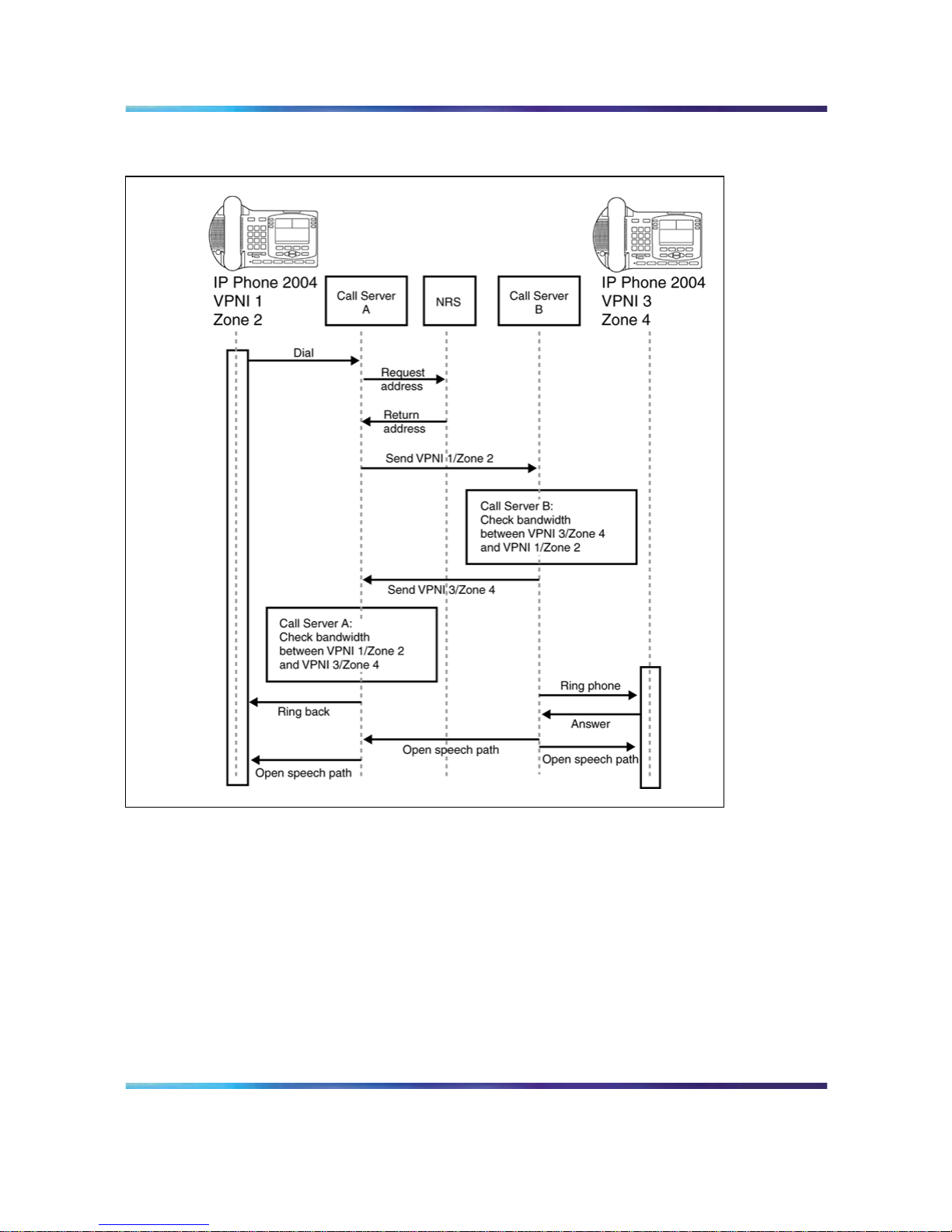
Adaptive Network Bandwidth Management 73
Figure 17
Call Progress with Adaptive Network Bandwidth Management
Zone bandwidth management and Adaptive Network Bandwidth
Management
Using Element Manager or the Command Line Interface (CLI), previously
configured zones (except Zone 0) can have the Adaptive Network Bandwidth
Management feature turned on or off. Once turned on, alarm threshold
levels and the QoS coefficients can be adjusted from the default values.
Adaptive Network Bandwidth Management cannot be enabled for Zone 0.
When Adaptive Network Bandwidth Management is enabled for a particular
zone on the Call Server, the zone appears in the zone table. The zone table
can be displayed using Element Manager or LD 117. When a call is made
from the configured zone to another zone, the bandwidth used appears in
the zone table.
Nortel Communication Server 1000
Branch Office Installation and Commissioning
NN43001-314 01.02 Standard
Release 5.0 20 June 2007
Copyright © 2007, Nortel Networks
.
Page 74

74 Bandwidth Management
When a call is made from a zone with Adaptive Network Bandwidth
Management enabled, to a third party gateway, which has no zone, then the
zone of the Virtual Trunk (VTRK) is used and appears in the zone table.
Figure 18 "Adaptive Network Bandwidth Management graph" (page 74)
shows an example of the bandwidth changes.
Figure 18
Adaptive Network Bandwidth Management graph
When a Call Server receives a QoS alarm, the two zones that originated
the alarm are determined. Using this information, the Call Server reduces
the bandwidth limit between the two zones. This zone-to-zone bandwidth
limit (in effect at any particular time) is known as the Sliding Maximum
Bandwidth Limit and is a percentage of the Configured Interzone bandwidth
limit. The Sliding Maximum value is displayed using the prt interzone
command. The QoS Factor % is also displayed and is the percentage of
the Sliding Maximum versus the configured allowable bandwidth. The Call
Server checks the Network Bandwidth zone management tables for the
originating and terminating zones of the new call to determine the available
bandwidth for the call.
For more information about alarms, refer to Software Input/Output: System
Messages (NN43001-712).
When feedback indicates a significant QoS change in a zone, the Call
Server reduces the available bandwidth (Sliding Maximum Bandwidth Limit)
in the zone until the QoS reaches a satisfactory level. Once satisfactory
QoS is reached, the bandwidth is slowly raised until either the full bandwidth
is available or until QoS degrades again. Bandwidth changes can be
configured to be gradual (to reduce rapid swings and variations) or rapid.
Nortel Communication Server 1000
Branch Office Installation and Commissioning
NN43001-314 01.02 Standard
Release 5.0 20 June 2007
Copyright © 2007, Nortel Networks
.
Page 75

Adaptive Network Bandwidth Management 75
Multiple Appearance Directory Numbers (MADN) can exist on different
zones. Calls to an MADN are handled the same as other IP Phone calls,
and are subject to the same bandwidth limitations.
New SNMP alarms are provided to monitor the system. When the
bandwidth limit between zones is reduced below configured levels, an alarm
is raised. A Warning alarm and an Unacceptable alarm, each corresponding
to a drop below a configured threshold, are used. When the bandwidth
returns to normal, the alarm is cleared. If the bandwidth limit reaches
zero, an additional Unacceptable alarm is raised. These alarms allow the
system administrator to monitor the system and take corrective action
when required.
Adaptive Network Bandwidth Management configuration
parameters
Packet Loss (pl), Jitter (j) and Delay (d) measurements, along with the R
factor (r) in IP Phone 200x Phase II telephones, are used to calculate the
QoS level for the zones. The coefficients for these QoS measurements
packet loss (Cpl), jitter (Cj), delay (Cd), and the R factor (Cr) can be
configured and are used to calculate the rate of bandwidth change.
Increasing them from their default values causes the Sliding Maximum to
decrease faster in response to the specific QoS alarm.
The QoS Coefficient (CQoS) can be varied from its default value. Increasing
this value causes the Sliding Maximum to change more rapidly in response
to QoS alarms. However, making this value too large will result in loss
of overall bandwidth, as shown in Figure 19 "Effect of the default CQos
Coefficient" (page 75) below and Figure 20 "Effect of a higher CQoS
Coefficient" (page 76).
Figure 19
Effect of the default CQos Coefficient
Nortel Communication Server 1000
Branch Office Installation and Commissioning
NN43001-314 01.02 Standard
Release 5.0 20 June 2007
Copyright © 2007, Nortel Networks
.
Page 76

76 Bandwidth Management
Figure 20
Effect of a higher CQoS Coefficient
Other configurable coefficients used in the calculation are the QoS
Coefficient (CQoS), QoS Response Time Increase (ZQRT), and QoS
Response Time Interval (ZQRTI). CQoS, Cr, Cd, Cpl, and Cj control the
rate of bandwidth decrease, while ZQRT and ZQRTI control the rate of
bandwidth increase.
The Call Admission Control (CAC) Validity Time Interval (CACVT) is used to
control the length of time that records from a Call Server are saved in the
Bandwidth Management table. If there have not been any calls between two
Call Servers within the configured time, the Call Server is removed from the
table. For example, if Call Server A has Call Server B in the table, and no
call has been placed between A and B for the CACVT time, then Call Server
A removes all Call Server B records in the table.
Limitations
Virtual Office IP Phones are not subject to bandwidth limitations. They
may not have the correct zone information configured. They can also be
controlled by a Call Server that is not responsible for the particular zone.
Thus, bandwidth management is not possible for these phones.
Feature packaging
The Adaptive Network Bandwidth Management feature requires the
following packages:
•
QoS Enhanced Reporting (PVQM) package 401
• Call Admission Control (CAC) package 407
ATTENTION
Package 401, QoS Enhanced Reporting (PVQM), is required if the R value from
the Phase II IP Phones is to be reported and used in the calculations.
Nortel Communication Server 1000
Branch Office Installation and Commissioning
NN43001-314 01.02 Standard
Release 5.0 20 June 2007
Copyright © 2007, Nortel Networks
.
Page 77

Adaptive Network Bandwidth Management 77
Configuration rules
The configuration rules for Adaptive Network Bandwidth Management are
as follows:
•
Each main office Call Server in a network must have a unique non-zero
VPNI.
•
All branch offices(MG1000B or SRG) associated with a particular main
office must have the same VPNI as the main office Call Server.
•
All IP Phones (other than specific IP SoftPhone 2050s) and DSP
endpoints on a Call Server must be configured for the same zone.
•
IP SoftPhone 2050s being used remotely must be configured for Zone 0.
•
Branch Office systems(MG 1000B or SRG) should tandem all calls
through the main office Call Server to allow bandwidth monitoring and
control. In this case, the media path is direct between the Branch Office
and any point in the network.
•
Trunk Route Optimization (TRO) must be disabled between the main
office Call Server and the MG 1000B Core or SRG. In this case, the
media path is direct between the Branch Office and any point in the
network.
•
Adaptive Network Bandwidth Management parameters are configured
on the main office only and must not be configured at the branch offices.
Configuring Adaptive Network Bandwidth Management
The following is a summary of the tasks necessary to configure Adaptive
Network Bandwidth Management in the network.
1. Enable the Call Admission Control (CAC) package.
2. Configure CAC in Element Manager or LD 117:
a. Configure the VPNI on the main office and branch offices.
b. Configure both the main office and Branch Office zones at the main
office.
c. Configure the Branch Office zone on the MG 1000B Core or SRG.
d. Configure the interzone and intrazone bandwidth limits at the main
office and MG 1000B Core or SRG.
e. Enable Adaptive Network Bandwidth Management for the zones
on the main office Call Server.
f. If required, alter the Adaptive Network Bandwidth Management
parameters in keeping with the information in ""Advanced
Configuration Notes" (page 78)" below.
3. Tandem the outbound Branch Office calls by configuring the NRS.
Nortel Communication Server 1000
Branch Office Installation and Commissioning
NN43001-314 01.02 Standard
Release 5.0 20 June 2007
Copyright © 2007, Nortel Networks
.
Page 78

78 Bandwidth Management
4. Tandem the inbound Branch Office calls by creating a dialing plan which
routes all calls destined for the Branch Office through the main office.
Advanced Configuration Notes
1. The default values for Cpl, Cj, Cd, Cr and CQos can be increased to
increase the response time for Sliding Maximum changes. However,
increasing them can cause the Sliding Maximum to temporarily decrease
to a lower value then necessary, resulting in the needless blocking of
interzone calls.
2. Increasing the value of ZQRT will increase the speed at which the
Sliding Maximum increases. The same effect can be achieved by
decreasing ZQRTI. However, changing these values can cause the
Sliding maximum to oscillate until the network degradation is removed.
Configuration using Element Manager
Element Manager can be used to enable and configure the feature.
The zone must exist before it can be configured for Adaptive Network
Bandwidth Management. Refer to IP Peer Networking: Installation and
Configuration (NN43001-313) for instruction on how to create and configure
basic properties of the zone.
To configure the Adaptive Network Bandwidth Management feature, select
a zone on the Zones web page (see Figure 14 "Zones web page" (page
66)) and click Adaptive Network Bandwidth Management and CAC. The
Adaptive Network Bandwidth Management and CAC web page opens,
as shown in Figure 21 "Adaptive Network Bandwidth Management and
CAC web page" (page 79).
ATTENTION
Do not configure Adaptive Networks Bandwidth Management for Zone 0 or Virtual
Trunk zones.
Nortel Communication Server 1000
Branch Office Installation and Commissioning
NN43001-314 01.02 Standard
Release 5.0 20 June 2007
Copyright © 2007, Nortel Networks
.
Page 79

Adaptive Network Bandwidth Management 79
Figure 21
Adaptive Network Bandwidth Management and CAC web page
If the Adaptive Network Bandwidth Management feature is enabled using
the Enable Call Admission Control feature (ZCAC) check box, then the
other parameters can be adjusted as required.
Table 6 "Adaptive Network Bandwidth Management and CAC fields" (page
79) shows the fields in the Adaptive Network Bandwidth Management
and CAC web page, the field definitions, and their LD 117 command
equivalent.
Table 6
Adaptive Network Bandwidth Management and CAC fields
Field Title Field Definition
LD 117
equivalents
Enable Call Admission
Control Feature (CAC)
Control the CAC feature for the zone
•
Enable (check box selected)
•
disable (clear the check box)
ENL ZCAC
DIS ZCAC
Nortel Communication Server 1000
Branch Office Installation and Commissioning
NN43001-314 01.02 Standard
Release 5.0 20 June 2007
Copyright © 2007, Nortel Networks
.
Page 80

80 Bandwidth Management
Field Title Field Definition
LD 117
equivalents
QoS Response Time
Increase (ZQRT)
Bandwidth limit increment, as a percentage of
the QoS factor for the zone
CHG ZQRT
QoS Response Time
Interval (ZQRTI)
Time (in minutes) between bandwidth limit
increments
CHG ZQRTI
Warning Alarm Threshold
(ZQWAT)
A QoS value, which is lower than this value, but
higher than the Critical (Unacceptable) Alarm
Threshold, triggers a Major Alarm.
CHG ZQWAT
Critical Alarm Threshold
(ZQUAT)
A QoS value, which is lower than this value,
triggers an Unacceptable (Critical) Alarm.
CHG ZQUAT
R Alarm Coefficient (CR) The R (Cr) coefficient is used to calculate the
QoS value for the zone.
CHG CR
Packet Loss Alarm
Coefficient (CPL)
The Packet Loss (Cpl) coefficient is used to
calculate the QoS value for the zone.
CHG CPL
Delay Alarm Coefficient
(CD)
The Delay (Cd) coefficient is used to calculate
the QoS value for the zone.
CHG CD
Jitter Alarm Coefficient (CJ) The Jitter (Cj) coefficient is used to calculate the
QoS value for the zone.
CHG CJ
Coefficient of QoS (CQoS) The Coefficient of QoS (CQoS) is used to
calculate the overall QoS value for the zone.
CHG CQOS
Recent Validity Time
Interval (CACVT)
Amount of time (in hours) for zone-to-zone
record validity. Once this interval expires,
records for unused zones are purged from the
tables.
CHG CACVT
Configuration using Command Line Interface
You can also configure the Adaptive Network Bandwidth Management
feature using LD 117.
LD 117 - Configure Adaptive Network Bandwidth Management.
Command
Description
CHG CACVT <Zone> <Interval>
Configure the zone-to-zone record validity time interval, where:
•
Zone = 1-255
•
Interval = 1-(48)-255
CHG CD <Zone> <Cd>
Nortel Communication Server 1000
Branch Office Installation and Commissioning
NN43001-314 01.02 Standard
Release 5.0 20 June 2007
Copyright © 2007, Nortel Networks
.
Page 81

Adaptive Network Bandwidth Management 81
Command
Description
Change the Cd coefficient in the formula that determines how quickly an alarm
reduces the Sliding Maximum bandwidth for the identified zone, where:
•
Zone = 1-255
•
Cd = Cd coefficient = 1-(50)-100
CHG CPL <Zone> <Cpl>
Change the Cpl coefficient in the formula that determines how quickly an alarm
reduces the Sliding Maximum bandwidth for the identified zone, where:
•
Zone = 1-255
•
Cpl = Cpl coefficient = 1-(50)-100
CHG CJ <Zone> <Jitter>
Change the Cj coefficient in the formula that determines how quickly an alarm
reduces the Sliding Maximum bandwidth for the identified zone, where:
• Zone = 1-255
•
Jitter = Jitter coefficient = 1-(50)-100
CHG CQOS <Zone> <QoS>
Change the QoS coefficient in the formula that determines how quickly an
alarm reduces the Sliding Maximum bandwidth for the identified zone, where:
•
Zone = 1-255
•
QoS = QoS coefficient = 1-(50)-100
CHG CR <Zone> <Cr>
Change the Cr coefficient in the formula that determines how quickly an alarm
reduces the Sliding Maximum bandwidth for the identified zone, where:
•
Zone = 1-255
• Cr = Cr coefficient = 1-(50)-100
CHG ZONE <zoneNumber> <intraZoneBandwidth> <intraZoneStrategy> <interZoneBandwidth>
<interZoneStrategy> [<zoneIntent> <zoneResourceType>]
Nortel Communication Server 1000
Branch Office Installation and Commissioning
NN43001-314 01.02 Standard
Release 5.0 20 June 2007
Copyright © 2007, Nortel Networks
.
Page 82

82 Bandwidth Management
Command
Description
Change the parameters of an existing zone, where:
•
zoneNumber = 1-255
• intraZoneBandwidth = 1000000 (Mbit/s)
•
intraZoneStrategy = intrazone preferred strategy
— Best Quality = BQ
— Best Bandwidth = BB
•
interZoneBandwidth = 1000000 (Mbit/s)
•
interZoneStrategy = intrazone preferred strategy
— Best Quality = BQ
— Best Bandwidth = BB
• zoneIntent = type of zone, where:
— MO = Main office zone
— BMG = Branch Media Gateway (Branch Office) zone
— VTRK = Virtual Trunk zone
•
zoneResourceType = resource intrazone preferred strategy
— shared DSP channels (default) = shared
— private DSP channels = private
In CS 1000 Release 5.0, the zones that were described with BMG designator
stay with BMG one, all the other zones are provided with MO designator. It is
possible to update zoneIntent using the CHG ZONE command.
CHG ZQRT <Zone> <Incr>
Change ZQRT, which is Response time increase by percentage. It is used to
determine the increase to the Sliding Maximum for the identified zone, where:
•
Zone = 1-255
•
Incr = increase value in percentage = 1-(10)-100
CHG ZQRTI <Zone> <Interval>
Nortel Communication Server 1000
Branch Office Installation and Commissioning
NN43001-314 01.02 Standard
Release 5.0 20 June 2007
Copyright © 2007, Nortel Networks
.
Page 83

Adaptive Network Bandwidth Management 83
Command
Description
Change the QoS Response Time Interval while alarms are not coming, to
increase the Sliding Maximum for the identified zone, where:
•
Zone = 1-255
•
Interval = interval in minutes = 1-(5)-120
CHG ZQUAT <Zone> <Thres>
Change the QoS Unacceptable Alarm Threshold value for the identified zone,
where:
•
Zone = 1-255
•
Thres = threshold value = 1-(75)-99
When the zone-to-zone QoS value drops below the threshold value, the alarm
is presented. This value must be below the value of ZQWAT.
CHG ZQWAT <Zone> <Thres>
Change the QoS Warning Alarm Threshold value for the identified zone, where:
• Zone = 1-255
•
Thres = threshold value = 1-(85)-99
When the zone-to-zone QoS value drops below the threshold value, the alarm
is presented. The value for ZQWAT must be higher than the value of ZQUAT.
NEW ZONE <zoneNumber> [<intraZoneBandwidth> <intraZoneStrategy> <interZoneBandwidth>
<interZoneStrategy> <zoneIntent> <zoneResourceType>]
•
zoneNumber = 1-255
•
intraZoneBandwidth = 1000000 (Mbit/s)
•
intraZoneStrategy = BQ (Best Quality)
• interZoneBandwidth = 1000000 (Mbit/s)
•
interZoneStrategy = intrazone preferred strategy
— Best Quality = BQ
— Best Bandwidth = BB
•
zoneIntent = type of zone, where:
— MO = Main office zone
Nortel Communication Server 1000
Branch Office Installation and Commissioning
NN43001-314 01.02 Standard
Release 5.0 20 June 2007
Copyright © 2007, Nortel Networks
.
Page 84

84 Bandwidth Management
Command
Description
— BMG = Branch Media Gateway (Branch Office) zone
— VTRK = Virtual Trunk zone
•
zoneResourceType = resource intrazone preferred strategy
— shared DSP channels (default) = shared
— private DSP channels = private
DIS ZCAC <Zone>
Disables the Call Admission Control (CAC) feature for the specified zone,
where:
•
Zone = 1-255
Disables the feature on a zone-by-zone basis.
ENL ZCAC <Zone>
Enables the Call Admission Control (CAC) feature for the specified zone,
where:
•
Zone = 1-255
Enables the feature on a zone-by-zone basis.
Maintenance commands
The Adaptive Network Bandwidth Management feature can be maintained
using Element Manager or LD 117.
Maintenance using Element Manager
The CAC parameters, intrazone statistics, and interzone statistics for one of
more zones are available in Element Manager from the Zones web page,
shown in Figure 14 "Zones web page" (page 66). To view the intrazone
or interzone statistics, use Procedure 1 "Printing intrazone and interzone
statistics for a zone" (page 67). To display the CAC parameters, follow the
steps in Procedure 2 "Displaying CAC parameters for one or more zones"
(page 85).
Nortel Communication Server 1000
Branch Office Installation and Commissioning
NN43001-314 01.02 Standard
Release 5.0 20 June 2007
Copyright © 2007, Nortel Networks
.
Page 85

Adaptive Network Bandwidth Management 85
Procedure 2
Displaying CAC parameters for one or more zones
Step Action
1
Select IP Network > Zones from the navigator.
The Zones web page opens (see Figure 14 "Zones web page"
(page 66)).
2
Click Maintenance Commands for Zones (LD 117).
The Maintenance Commands for Zones web page opens, as
shown in Figure 15 "Maintenance Commands for Zones web
page" (page 68). This page lists all the configured zones and their
intrazone statistics by default.
3
Select Print Adaptive Network Bandwidth Management and CAC
Parameters (PRT ZCAC) from the Action drop-down list.
4
Select a zone from the Zone Number drop-down list, by doing one
of the following:
•
Select ALL to print statistics for all zones.
•
Select a specific zone number to display statistics for a specific
zone.
5
Click Submit.
The Maintenance Commands for Zones web page reopens,
displaying the statistics for the specified zone or zones. A blank
field indicates that statistic is either not available or not applicable to
that zone.
Figure 22 "Element Manager - CAC parameters" (page 86) shows
an example of the CAC parameters for all Zones.
—End—
Nortel Communication Server 1000
Branch Office Installation and Commissioning
NN43001-314 01.02 Standard
Release 5.0 20 June 2007
Copyright © 2007, Nortel Networks
.
Page 86

86 Bandwidth Management
Figure 22
Element Manager - CAC parameters
Maintenance using LD 117
The same information can be displayed using commands in LD 117.
LD 117 - Display Adaptive Network Bandwidth Management information
Command
Description
CLR CACR <nearZone> [<nearVPNI>] [<farZone>] [<farVPNI>]
Clear zone-to-zone record for near (VPNI-Zone) for far (VPNI-Zone), where:
•
nearZone = 0-255
•
nearVPNI = 1-16383
•
farZone = 0-255
•
farVPNI = 1-16383
PRT INTRAZONE [<zone>]
Nortel Communication Server 1000
Branch Office Installation and Commissioning
NN43001-314 01.02 Standard
Release 5.0 20 June 2007
Copyright © 2007, Nortel Networks
.
Page 87

Adaptive Network Bandwidth Management 87
Command
Description
Print intrazone statistics for the identified zones, where:
•
zone = ALL or 1-255
The output of this command displays the following information:
•
Zone
•
State = ENL/DIS
•
Type = PRIVATE/SHARED
•
Strategy = BB/BQ
•
MO/VTRK/BMG = zoneIntent
•
Bandwidth = Kbps
•
Usage = Kbps
•
Peak = %
Figure 23 "Sample output for PRT INTRAZONE command" (page 89) shows
an example of the output for this command.
PRT INTERZONE [<nearZone>] [<nearVPNI>] [<farZone>] [<farVPNI>]
Print interzone statistics for the specific VPNI zone; where:
•
nearZone = ALL or 1-255
•
nearVPNI = 1-16383
•
farZone = 0-255
• farVPNI = 1-16383
The output of this command displays the following information:
• Near end Zone
•
Near end VPNI
•
Far end Zone
•
Far end VPNI
• State = ENL/DIS
•
Type = PRIVATE/SHARED
Nortel Communication Server 1000
Branch Office Installation and Commissioning
NN43001-314 01.02 Standard
Release 5.0 20 June 2007
Copyright © 2007, Nortel Networks
.
Page 88

88 Bandwidth Management
Command
Description
•
Strategy = BB/BQ
• MO/VTRK /BMG= zoneIntent
•
QoS factor = %
•
Bandwidth configured = Kbps
•
Sliding max = Kbps
• Usage = Kbps
•
Peak = %
•
Call = Cph
•
Alarm = Aph
The report rows are grouped as:
•
First row = summary bandwidth usage per near zone
• Next rows = bandwidth usage per near (VPNI- Zone) and far (VPNI - Zone)
Figure 24 "Sample output for PRT INTERZONE command" (page 90) shows
an example of the output for this command.
PRT ZCAC [<zone>]
Print CAC parameters for the specified zone, or for all zones, where:
•
zone = ALL or 1-255
The output of this command displays the following information:
•
Local ZONE = 1-255
•
State = ENL/DIS
•
CR = 1-100
•
CPL = 1-100
•
CD = 1-100
•
CJ = 1-100
•
CQOS = 1-100
• ZQRT = 1-100
Nortel Communication Server 1000
Branch Office Installation and Commissioning
NN43001-314 01.02 Standard
Release 5.0 20 June 2007
Copyright © 2007, Nortel Networks
.
Page 89

Adaptive Network Bandwidth Management 89
Command
Description
•
ZQRTI = 10-120
•
ZQUAT = 1-99
•
ZQWAT =1-99
• CACVT = 1-255
Sample outputs for PRT commands Figure 23 "Sample output for
PRT INTRAZONE command" (page 89) shows an example of the output
of the PRT INTRAZONE command. Figure 24 "Sample output for PRT
INTERZONE command" (page 90) shows an example of the output of the
PRT INTERZONE command.
Figure 23
Sample output for PRT INTRAZONE command
Nortel Communication Server 1000
Branch Office Installation and Commissioning
NN43001-314 01.02 Standard
Release 5.0 20 June 2007
Copyright © 2007, Nortel Networks
.
Page 90

90 Bandwidth Management
Figure 24
Sample output for PRT INTERZONE command
Tandem Bandwidth Management overview
In order for the main office to correctly keep track of all the bandwidth being
used to and from a Branch Office the call must be tandemed through the
main office. When calls are tandemed through the main office only the
signaling is tandemed, the actual voice bandwidth travels directly between
the source and destination.
Nortel Communication Server 1000
Branch Office Installation and Commissioning
NN43001-314 01.02 Standard
Release 5.0 20 June 2007
Copyright © 2007, Nortel Networks
.
Page 91

Dialing Plan Overview 91
Bandwidth utilization for the Branch Office is tracked at the main office and
can be displayed in LD 117 using the PRT INTERZONE command. To
provide the correct bandwidth utilization to the main office Call Server,
when a Branch Office is calling another node in the network, the calls must
be tandemed through the main office Call Server in both the inbound and
outbound direction.
Entering the main office Gateway endpoint identifier in the Tandem Endpoint
field for each Branch Office gateways configured on the NRS only provides
tandeming in the outbound direction from each Branch Office (from Branch
Office to main office).
To tandem calls through the main office in the inbound direction (from main
office to Branch Office), one must make use of the dialing plan capabilities
of the CS 1000 to first route the call to the main office. The main office
prepends a prefix to the dialed number and the number is routed to the
Branch Office.
Tandeming all Branch Office calls through the main office allows the main
office to keep track of the bandwidth being used at each Branch Office.
Application
This feature applies to the Branch Office and the Adaptive Bandwidth
Management feature. Specifically, it applies to calls made to and from the
Branch Office from either telephones registered locally at the Branch Office
(digital, analog [500/2500-type], and IP Phones) or trunks at the Branch
Office to another node in the network. It does not apply when using Branch
Office IP Phones that are registered with the main office (for example,
Normal Mode).
Dialing Plan Overview
Depending upon the type of dialing plan used in the network (Coordinated
Dialing Plan [CDP], or Uniform Dialing Plan [UDP] or a combination of both)
the general idea is to have all calls that are terminating at a Branch Office
first dial a number that will get routed to the main office associated with that
Branch Office. The main office recognizes this number as belonging to
the Branch Office and appends a tandem prefix to this number using Digit
Manipulation Index (DMI). The main office then routes the call to the Branch
Office while accounting for the additional bandwidth used.
See Figure 25 "A call between two branch offices tandems through the main
office" (page 92) for an example of a tandem call.
Nortel Communication Server 1000
Branch Office Installation and Commissioning
NN43001-314 01.02 Standard
Release 5.0 20 June 2007
Copyright © 2007, Nortel Networks
.
Page 92

92 Bandwidth Management
Figure 25
A call between two branch offices tandems through the main office
Figure 26 "General legend" (page 93) on Figure 26 "General legend" (page
93) shows a general legend for the figures in the following section.
Nortel Communication Server 1000
Branch Office Installation and Commissioning
NN43001-314 01.02 Standard
Release 5.0 20 June 2007
Copyright © 2007, Nortel Networks
.
Page 93

Network using Uniform Dialing Plan 93
Figure 26
General legend
Network using Uniform Dialing Plan
The following section provides general network configuration for a network
using UDP only.
Nortel Communication Server 1000
Branch Office Installation and Commissioning
NN43001-314 01.02 Standard
Release 5.0 20 June 2007
Copyright © 2007, Nortel Networks
.
Page 94

94 Bandwidth Management
Figure 27 "Scenario 1: UDP throughout the network" (page 94) shows two
or more main offices with their branch offices, within a larger network.
Callers within each main office/Branch Office "region" use UDP to place
calls between systems. Callers also use UDP to place calls across the IP
network to the other main office(s) and its (their) branch offices.
In a typical network, a full region uses a single Home Location Code
(HLOC). However, it is also possible, where the number of users requires it,
to have two or more codes, although using one for the main office and one
for each Branch Office is unlikely at best.
Figure 27
Scenario 1: UDP throughout the network
Common details
In general, if an HLOC is shared between two or more systems, the
provisioning at the main office gets more complex, unless all branch offices
share HLOCs with the main office. That is, if the main office has two or more
HLOCs, and one or more of these (but not necessarily the same one) is
used by every Branch Office, then provisioning is relatively straight forward.
Nortel Communication Server 1000
Branch Office Installation and Commissioning
NN43001-314 01.02 Standard
Release 5.0 20 June 2007
Copyright © 2007, Nortel Networks
.
Page 95

Network using Uniform Dialing Plan 95
Table 7 "Configuration details for the general case" (page 95) describes the
network configuration and the steps that a call takes during its setup.
Table 7
Configuration details for the general case
Region
Call progress
steps
Configuration detail and call progress
during call setup
1, 2, 3
UDP used for all calls within the region.
1, 2, 3
UDP used for region to region calls.
1, 2, 3
Prefixes for branch offices for regular calls are
required for all branch offices. May have additional
prefixes for E-911 calls, if required, or may share
prefixes.
11
All branch offices are provisioned at the NRS to route
all outbound calls (from the Branch Office) through
the main office. (NRS tandem configuration).
12
Main office sends all UDP calls to destinations
that are not its own Branch Office to the NRS with
unchanged dialled digits.
13
Main office sends all UDP calls to destinations that
are its own Branch Office to the NRS with a specific
gateway prefix in front of the dialled digits.
14
All branch offices delete the prefix and any LOC
codes, and terminate the calls. May be to a local set
or to a trunk.
2,3
Similar call setup steps take places for calls within
region 2 and 3.
Differences when every Branch Office HLOC is shared with the main
office
Table 8 "Provisioning details for this case" (page 95) shows the configuration
when the Branch Office HLOC is shared with the main office.
Table 8
Provisioning details for this case
Region Provisioning detail
1
Provisioning on the main office requires parsing to only "normal"
LOC identification and HLOC deletion.
1
LOC values that are on branch offices may be provisioned as
extended LOCs (> 3 digit codes).
Nortel Communication Server 1000
Branch Office Installation and Commissioning
NN43001-314 01.02 Standard
Release 5.0 20 June 2007
Copyright © 2007, Nortel Networks
.
Page 96

96 Bandwidth Management
Region Provisioning detail
1
The DMI for the Branch Office "LOC" inserts a gateway routing
prefix in front of the number.
2,3
Similar configuration, as above, applies to regions 2 and 3.
Call between two branch offices associated with the same main office
The following scenarios describe calls between two branch offices that
belong to the same main office. the different scenarios described below
vary vary in the manner in which the HLOC is architected; branch offices
have same HLOC as the main office, branch offices have a different HLOC
than the main office and so on.
Every Branch Office HLOC is shared with the main office
In the following example, the HLOC of all the branch offices and the HLOC
of the main office are all the same. See Figure 28 "Call flow for Scenario 1 -
local call" (page 96).
Figure 28
Call flow for Scenario 1 - local call
1. The Branch Office user dials 6-395-3456. The system transmits
395-3456 to the NRS. The NRS checks its provisioning, and determines
that all calls are to be sent to the main office; it directs the call to the
main office.
Nortel Communication Server 1000
Branch Office Installation and Commissioning
NN43001-314 01.02 Standard
Release 5.0 20 June 2007
Copyright © 2007, Nortel Networks
.
Page 97

Network using Uniform Dialing Plan 97
2. The Branch Office sends the call to 395-3456 to the main office.
3. The main office determines that this is LOC 39534, to another Branch
Office, with gateway routing prefix 552. The system inserts the
prefix and transmits 552-395-3456 to the NRS. The NRS checks its
provisioning, and determines that all calls to prefix 552 are to be sent to
Branch Office A2; it directs the call to the Branch Office.
4. The main office sends the call to 552-395-3456 to the Branch Office.
The Branch Office deletes the prefix and the HLOC, and rings set 3456.
No Branch Office HLOC is shared with the main office, but can be
shared with another Branch Office
In this example, the HLOC of the branch offices are the same but the HLOC
of the main office is different. See Figure 29 "Call flow for Scenario 1 -
local call" (page 97).
Figure 29
Call flow for Scenario 1 - local call
1. The Branch Office user dials 6-395-3456. The system transmits
395-3456 to the NRS. The NRS checks its provisioning, and determines
that all calls are to be sent to the main office; it directs the call to the
main office.
2. The Branch Office sends the call to 395-3456 to the main office.
Nortel Communication Server 1000
Branch Office Installation and Commissioning
NN43001-314 01.02 Standard
Release 5.0 20 June 2007
Copyright © 2007, Nortel Networks
.
Page 98

98 Bandwidth Management
3. The main office determines that this is LOC 39534 to another Branch
Office, with gateway routing prefix 552. The system inserts the
prefix and transmits 552-395-3456 to the NRS. The NRS checks its
provisioning, and determines that all calls to prefix 552 are to be sent to
Branch Office A2; it directs the call to the Branch Office.
4. The main office sends the call to 552-395-3456 to the Branch Office.
The Branch Office deletes the prefix and the HLOC and rings set 3456.
No Branch Office HLOC is shared with the main office or another
Branch Office
In this example, the HLOC is unique between all the branch offices and the
main office. See Figure 30 "Call flow for Scenario 1- local call" (page 98).
Figure 30
Call flow for Scenario 1- local call
1. The Branch Office user dials 6-395-3456. The system transmits
399-3456 to the Branch Office user dials 6-399-3456. NRS. The NRS
checks its provisioning, and determines that all calls are to be sent to
the main office; it directs the call to the main office.
2. The Branch Office sends the call to 399-3456 to the main office.
3. The main office determines that this is to another Branch Office,
with office prefix 552. The system inserts the prefix and transmits
552-399-3456 to the NRS. The NRS checks its provisioning, and
Nortel Communication Server 1000
Branch Office Installation and Commissioning
NN43001-314 01.02 Standard
Release 5.0 20 June 2007
Copyright © 2007, Nortel Networks
.
Page 99

Network using Uniform Dialing Plan 99
determines that all calls to prefix 552 are to be sent to Branch Office A2;
it directs the call to the Branch Office.
4. The main office sends the call to 552-399-3456 to the Branch Office.
The Branch Office deletes the prefix and the HLOC, and rings set 3456.
Call between branch offices associated with different main office
The following scenarios describe calls between two branch offices that
belong to different main offices. Note that the different scenarios described
below vary in the manner in which the HLOC is architected; branch offices
have same HLOC as the main office, branch offices have a different HLOC
than the main office and so on.
Every Branch Office HLOC is shared with the main office
In Figure 31 "Call flow for Scenario 1 - call to a remote Branch Office
(originator side)" (page 99), the first half of the call setup is shown (the
originator side is side A). In this example, the Branch Office and the main
office share the same HLOC. In Figure 32 "Call flow for Scenario 1 - call
to remote Branch Office (destination side)" (page 100), the second half of
the call is shown (the terminating side is side B).
Figure 31
Call flow for Scenario 1 - call to a remote Branch Office (originator side)
1. The Branch Office user dials 6-444-3456. The system transmits
444-3456 to the NRS. The NRS checks its provisioning, and determines
Nortel Communication Server 1000
Branch Office Installation and Commissioning
NN43001-314 01.02 Standard
Release 5.0 20 June 2007
Copyright © 2007, Nortel Networks
.
Page 100

100 Bandwidth Management
that all calls are to be sent to the main office; it directs the call to the
main office.
2. The Branch Office sends the call to 444-3456 to the main office.
3. The main office determines that this is to another main office. The
system transmits 444-3456 to the NRS. The NRS checks its provisioning,
and determines that this call goes to main office B.
Figure 32
Call flow for Scenario 1 - call to remote Branch Office (destination side)
1. Main office B determines that this is to LOC 44434, which is a local
Branch Office with prefix 225. The system transmits 225-444-3456 to
the NRS. The NRS checks its provisioning, and determines that this call
goes to Branch Office B1.
2. The main office sends the call to 225-444-3456 to the Branch Office.
The Branch Office deletes the prefix, discovers the call is to its HLOC
444, deletes the HLOC, and rings set 3456.
No Branch Office HLOC is shared with the main office, but can
be shared with another Branch Office
In Figure 33 "Call flow for Scenario 1 - call to remote Branch Office
(originator side)" (page 101), the first half of the call is shown (originator
side of the call). In Figure 34 "Call flow for Scenario 1 - call to remote
Branch Office (destination side)" (page 102), the second half of the call is
shown (destination side of the call).
Nortel Communication Server 1000
Branch Office Installation and Commissioning
NN43001-314 01.02 Standard
Release 5.0 20 June 2007
Copyright © 2007, Nortel Networks
.
 Loading...