

Page 1

Nortel Metro Ethernet Routing Switch 8600
Installation — SFP, XFP,
GBIC, and OADM Hardware
Components
NN46220-301
.
Page 2

Document status: Standard
Document version: 01.01
Document date: 1 May 2008
Copyright © 2008, Nortel Networks
All Rights Reserved.
Sourced in Canada and the United States of America
This document is protected by copyright laws and international treaties. All information, copyrights and any other
intellectual property rights contained in this document are the property of Nortel Networks. Except as expressly
authorized in writing by Nortel Networks, the holder is granted no rights to use the information contained herein and
this document shall not be published, copied, produced or reproduced, modified, translated, compiled, distributed,
displayed or transmitted, in whole or part, in any form or media.
In the interest of improving internal design, operational function, and/or reliability, Nortel Networks Inc. reserves the
right to make changes to the products described in this document without notice.
Nortel Networks Inc. does not assume any liability that may occur due to the use or application of the product(s) or
circuit layout(s) described herein.
Page 3

Contents
New in this release 7
Features 7
Other changes 8
Introduction 9
Acronyms 9
Safety and regulatory information 11
Handling, safety, and environmental guidelines 11
Care of fiber optic equipment 12
Product safety warnings and information 16
Electromagnetic interference compliance 17
3
SFPs 7
XFPs 8
SFP and XFP power consumption 8
Electrostatic discharge prevention 11
Fiber optic cable care 12
Fiber optic connector care 13
Job aid: connector cleaning tools and materials 14
Cleaning single SC and FC connectors 14
Cleaning duplex SC connectors 15
Cleaning receptacles 15
Small form factor pluggable transceivers 21
Selecting an SFP 21
SFPs 22
Procedure job aid: SFPs and common applications 22
Procedure job aid: SFP models without DDI support 22
Procedure job aid: SFP models with DDI support 23
Installing an SFP 25
Procedure job aid: locking and extractor mechanisms 27
Removing an SFP 28
Gigabit interface converters 31
Selecting a GBIC 31
Procedure job aid: GBIC models 32
Installing a GBIC 32
Installation — SFP, XFP, GBIC, and OADM Hardware Components
Copyright © 2008, Nortel Networks
.
Nortel Metro Ethernet Routing Switch 8600
NN46220-301 01.01 Standard
5.0 1 May 2008
Page 4

4 Contents
Removing a GBIC 33
10 Gigabit small form factor pluggable transceivers 35
Selecting an XFP 35
Procedure job aid: XFP models 36
Installing an XFP 37
Removing an XFP 39
Optical multiplexers 41
Multiplexing equipment 41
Installing the shelf 42
Installing a multiplexer 42
Connecting an OADM 42
Procedure job aid: Optical add/drop multiplexers 43
Connecting an OMUX 43
Procedure job aid: optical multiplexer/demultiplexer 44
Removing a multiplexer 44
SFP specifications 45
SFP labels 46
General SFP specifications 46
100BASE-FX SFP specifications 47
100-Base LX SFP specifications 48
100-Base BX10-U/D SFP specifications 48
100-Base ZX SFP specifications 49
1000BASE-T SFP specifications 50
1000BASE-SX (LC) SFP specifications 50
1000BASE-SX (MT-RJ) SFP specifications 51
1000BASE-LX SFP specifications 52
1000BASE-XD CWDM SFP specifications 52
1000BASE-ZX CWDM SFP specifications 53
1000BASE-SX DDI SFP specifications 54
1000BASE-LX DDI SFP specifications 54
1000BASE-XD DDI 1310 nm SFP specifications 55
1000BASE-XD DDI 1550 nm SFP specifications 56
1000BASE-ZX DDI SFP specifications 56
1000BASE-XD DDI CWDM SFP specifications 57
1000BASE-ZX DDI CWDM SFP specifications 58
1000Base CWDM SFP 58
1000BASE-BX DDI SFP specifications 59
1000BASE-EX DDI SFP specifications 61
GBIC specifications 63
GBIC labels 63
General GBIC specifications 64
1000BASE-T GBIC specifications 64
Installation — SFP, XFP, GBIC, and OADM Hardware Components
Copyright © 2008, Nortel Networks
.
Nortel Metro Ethernet Routing Switch 8600
NN46220-301 01.01 Standard
5.0 1 May 2008
Page 5

Contents 5
1000BASE-SX GBIC specifications 65
1000BASE-LX GBIC specifications 66
1000BASE-XD GBIC specifications 68
1000BASE-ZX GBIC specifications 68
1000BASE-EX CWDM GBIC specifications 69
XFP specifications 73
XFP labels 73
General XFP specifications 74
10GBASE-SR XFP specifications 74
10GBASE-LR/LW XFP specifications 76
10GBASE-ER/EW XFP specifications 77
10GBASE-ZR/ZW XFP specifications 79
10GBASE DWDM XFP specifications 80
Multiplexer specifications 83
Installation — SFP, XFP, GBIC, and OADM Hardware Components
Copyright © 2008, Nortel Networks
.
Nortel Metro Ethernet Routing Switch 8600
NN46220-301 01.01 Standard
5.0 1 May 2008
Page 6

6 Contents
Installation — SFP, XFP, GBIC, and OADM Hardware Components
Copyright © 2008, Nortel Networks
.
Nortel Metro Ethernet Routing Switch 8600
NN46220-301 01.01 Standard
5.0 1 May 2008
Page 7

New in this release
The following sections describe what’s new in Nortel Metro Ethernet
Routing Switch 8600 Installation — SFP, XFP, GBIC , and OADM Hardware
Components (NN46220-301) for Release 5.0.
Features
Release 5.0 provides support for new SFPs, a new XFP, and DWDM XFPs.
In addition, R modules and RC modules support SFPs and XFPs used in
the following Nortel optical products: Optical Metro 3500, Optical Metro
5200/5100, and Optical Metro Edge 6500. In Release 5.0 all R and RC
modules support all SFPs and XFPs with a product engineering code (PEC)
that starts with AA or NT.
For details on modules, see Nortel Metro Ethernet Routing Switch 8600
Installation—Modules (NN46220-306).
SFPs
The newly supported SFPs are as follows:
7
•
NTK591LH/MH/NH/PH/QJ/RH/SH/TH
•
AA1419074-E6
•
AA1419076-E6
•
AA1419077-E6
•
AA1419081-E5
•
AA1419082-E5
•
AA1419083-E5
•
AA1419084-E5
For specifications on the newly supported SFPs , see "General SFP
specifications" (page 46).
Installation — SFP, XFP, GBIC, and OADM Hardware Components
Copyright © 2008, Nortel Networks
.
Nortel Metro Ethernet Routing Switch 8600
NN46220-301 01.01 Standard
5.0 1 May 2008
Page 8

8 New in this release
XFPs
The newly supported XFPs are as follows:
•
For specifications on newly supported XFPs, see "XFP specifications"
(page 73).
Note: Due to hexidecimal to decimal rounding, and vice-versa, the
wavelengthnumbers provided by the XFP manufacturer and reported by the
Metro Ethernet Routing Switch 8600 system may vary slightly.
Other changes
SFP and XFP power consumption
The chapters "SFP specifications" (page 45) and "XFP specifications"
(page 73) each include a note to reference a section entitled "SFPs, XFPs,
R and RC modules, and power consumption" in Installation—Modules
(NN46220-306).
DWDM XFPs: NTK587AY/BA/BC/BE/BG/BJ/BL/BN/BQ/BS/BU-E5
Installation — SFP, XFP, GBIC, and OADM Hardware Components
Copyright © 2008, Nortel Networks
.
Nortel Metro Ethernet Routing Switch 8600
NN46220-301 01.01 Standard
5.0 1 May 2008
Page 9
Introduction
This document provides installation instructions and technical specifications
for:
•
Small Form Factor Pluggable (SFP) transceivers
•
Gigabit Interface Converters (GBIC)
•
10 Gigabit Small Form Factor Pluggable (XFP) transceivers
•
Optical multiplexers
For a list of supported SFPs, GIBCs, and XFPs see your latest
product-specific release notes. Information contained in the Release Notes
takes precedence over any information contained in this document.
Acronyms
The following table defines acronyms used in this document.
Table 1 Acronyms
9
CDR clock data recovery
CWDM coarse wavelength-division multiplexing
DMD differential mode delay
DWDM dense wavelength-division multiplexing
EMI electromagnetic interference
ESD electrostatic discharge
GBIC Gigabit Interface Converters
LC latch connector
LED light emitting diode
MAN metropolitan area network
MMF multimode fiber
OMA Optical Modulation Amplitude
OMUX Optical Multiplexer/Demultiplexer
Installation — SFP, XFP, GBIC, and OADM Hardware Components
Copyright © 2008, Nortel Networks
.
Nortel Metro Ethernet Routing Switch 8600
NN46220-301 01.01 Standard
5.0 1 May 2008
Page 10

10 Introduction
RJ registered jack
SC snap-in connector
SFP small form factor pluggable
SMF single mode fiber
TPE Twisted Pair Ethernet
UTP unshielded twisted pair
WAN wide area network
WDM wavelength-division multiplexing
XFP 10 Gigabit Ethernet small form factor pluggable
Installation — SFP, XFP, GBIC, and OADM Hardware Components
Copyright © 2008, Nortel Networks
.
Nortel Metro Ethernet Routing Switch 8600
NN46220-301 01.01 Standard
5.0 1 May 2008
Page 11

Safety and regulatory information
This section contains important safety and regulatory information. Read this
section before you install Small Form Factor Pluggable (SFP) transceivers,
10 Gigabit SFP (XFP) transceivers, or GigaBit Interface Converters (GBIC).
Navigation
•
"Handling, safety, and environmental guidelines" (page 11)
• "Care of fiber optic equipment" (page 12)
•
"Product safety warnings and information" (page 16)
•
"Electromagnetic interference compliance" (page 17)
Handling, safety, and environmental guidelines
Before you install a GBIC, SFP, or XFP, read the following handling, safety,
and environmental guidelines:
•
GBICs, SFPs, and XFPs are static sensitive. To prevent damage from
electrostatic discharge (ESD), see "Electrostatic discharge prevention"
(page 11).
11
•
GBICs, SFPs, and XFPs are dust sensitive. When you store a GBIC,
SFP, or XFP, or when you disconnect it from a fiber optic cable, always
keep a dust cover over the GBIC, SFP, or XFP optical bore.
•
To clean contaminants from the optical bores of a GBIC, SFP, or XFP,
use an alcohol swab or equivalent to clean the ferrules of the optical
connector.
•
Dispose of this product according to all national laws and regulations.
Electrostatic discharge prevention
To prevent equipment damage, observe the following electrostatic discharge
(ESD) precautions when handling or installing the components.
•
Ground yourself and the equipment to an earth or building ground. Use
a grounded workbench mat (or foam that dissipates static charge) and
a grounding wrist strap. The wrist strap should touch the skin and be
grounded through a one megaohm resistor.
Installation — SFP, XFP, GBIC, and OADM Hardware Components
Copyright © 2008, Nortel Networks
.
Nortel Metro Ethernet Routing Switch 8600
NN46220-301 01.01 Standard
5.0 1 May 2008
Page 12

12 Safety and regulatory information
•
Do not touch anyone who is not grounded.
•
Leave all components in their ESD-safe packaging until installation, and
use only a static-shielding bag for all storage, transport, and handling.
•
Clear the area of synthetic materials such as polyester, plastic, vinyl, or
styrofoam because these materials carry static electricity that damages
the equipment.
Care of fiber optic equipment
Fiber optic equipment must be kept clean and damage-free. Use the
information in this section to properly maintain and care for fiber optic
equipment.
Care of fiber optic equipment navigation
•
"Fiber optic cable care" (page 12)
•
"Fiber optic connector care" (page 13)
•
"Job aid: connector cleaning tools and materials" (page 14)
•
"Cleaning single SC and FC connectors" (page 14)
•
"Cleaning duplex SC connectors" (page 15)
•
"Cleaning receptacles" (page 15)
Fiber optic cable care
Although the glass fiber of fiber optic cable is protected with reinforcing
material and plastic insulation, it is subject to damage. Use the following
precautions to avoid damaging the glass fiber.
•
Do not kink, knot, or vigorously flex the cable.
•
Do not bend the cable to less than a 40 mm radius.
•
Do not stand on fiber optic cable; keep the cable off the floor.
•
Do not pull fiber optic cable any harder than you would a cable containing
copper wire of comparable size.
•
Do not allow a static load of more than a few pounds on any section
of the cable.
•
Place protective caps on fiber optic connectors that are not in use.
•
Store unused fiber optic patch cables in a cabinet, on a cable rack, or
flat on a shelf.
Frequent overstressing of fiber optic cable causes progressive degeneration
that leads to failure.
Installation — SFP, XFP, GBIC, and OADM Hardware Components
Copyright © 2008, Nortel Networks
.
Nortel Metro Ethernet Routing Switch 8600
NN46220-301 01.01 Standard
5.0 1 May 2008
Page 13
If you suspect damage to a fiber optic cable, either due to mishandling or
an abnormally high error rate observed in one direction, reverse the cable
pairs. If the high error rate appears in the other direction, replace the cable.
CAUTION
Do not crush fiber optic cable. If fiber optic cable is in the same
tray or duct with large, heavy electrical cables, it can be damaged
by the weight of the electrical cable.
Fiber optic connector care
Before connecting them to transmission equipment, test equipment,
patch panels, or other connectors, clean all fiber optic connectors. The
performance of an optical fiber connector depends on how clean the
connector and coupling are at the time of connection. Use the following
cleaning procedures when analyzing fiber connector integrity.
If a connector performs poorly after cleaning, visually inspect the connector
to determine the possible cause of the problem and to determine if it needs
replacing.
Care of fiber optic equipment 13
WARNING
Do not look into the end of fiber optic cable. The light source used
in fiber optic cables can damage your eyes.
To avoid getting debris in your eyes, wear safety glasses when
working with the canned air duster.
To avoid eye irritation on contact, wear safety glasses when
working with isopropyl alcohol.
Perform the following maintenance procedures to ensure that optical fiber
assemblies function properly. To prevent them from collecting dust, make
sure connectors are covered when not in use.
CAUTION
To prevent further contamination, clean fiber optic equipment only
when there is evidence of contamination.
To prevent contamination, make sure the optical ports of all active
devices are covered with a dust cap or optical connector.
To avoid the transfer of oil or other contaminants from your fingers
to the end face of the ferrule, handle connectors with care.
Installation — SFP, XFP, GBIC, and OADM Hardware Components
Copyright © 2008, Nortel Networks
.
Nortel Metro Ethernet Routing Switch 8600
NN46220-301 01.01 Standard
5.0 1 May 2008
Page 14
14 Safety and regulatory information
Job aid: connector cleaning tools and materials
You need the following tools and materials to clean fiber optic connectors.
•
Lint-free, nonabrasive wiping cloths
•
Cotton swabs, with a tightly wrapped and talcum-free tip
•
Optical-grade isopropyl alcohol (IPA)
•
Canned compressed air with extension tube
CAUTION
To avoid contamination, optical ports should only be cleaned when
there is evidence of contamination or reduced performance, or
during their initial installation.
To prevent oil contamination of connectors, do not use commercial
compressed air or house compressed air in place of canned
compressed air.
Do not allow the air extension tube to touch the bottom of the
optical port.
Cleaning single SC and FC connectors
Clean connectors so that the optical signal is minimally attenuated by the
connector.
Procedure steps
Step Action
1
2
3
4
Remove dust or debris by applying canned air to the cylindrical and
end-face surfaces of the connector.
Gently wipe the cylindrical and end-face surfaces with a pad or a
wipe dampened with optical-grade isopropyl alcohol.
Gently wipe the cylindrical and end-face surfaces with a dry, lint-free
tissue.
Dry the connector surfaces by applying canned air or letting them
air dry.
To prevent contamination, do not touch the connector surfaces after
cleaning; and cover them with dust caps if you are not going to use
them right away.
—End—
Installation — SFP, XFP, GBIC, and OADM Hardware Components
Copyright © 2008, Nortel Networks
.
Nortel Metro Ethernet Routing Switch 8600
NN46220-301 01.01 Standard
5.0 1 May 2008
Page 15

Cleaning duplex SC connectors
Clean connectors so that the optical signal is minimally attenuated by the
connector.
Procedure steps
Step Action
Care of fiber optic equipment 15
1
To remove or retract the shroud, do one of the following.
•
On removable shroud connectors, hold the shroud on the top and
bottom at the letter designation, apply medium pressure, and pull
it free from the connector body. Do not discard the shroud.
• On retractable shroud connectors, hold the shroud in its retracted
position.
2
Remove dust or debris from the ferrules and connector face with the
canned air duster.
3
Gently wipe the cylindrical and end-face surfaces of both ferrules
using a wipe saturated with optical-grade isopropyl alcohol.
4
Gently wipe the cylindrical and end-face surfaces of the connector
with Texwipe cloth (or dry lint-free tissue).
5
6
Blow dry the connector surfaces with canned air.
Using care to not touch the clean ferrules, gently push the shroud
back onto the connector until it seats and locks in place.
—End—
Cleaning receptacles
Clean connector receptacles or ports so that the optical signal is minimally
attenuated by the connection.
Procedure steps
Step Action
1
2 Clean the optical port by inserting a small dry swab into the
3
Installation — SFP, XFP, GBIC, and OADM Hardware Components
Copyright © 2008, Nortel Networks
.
Remove dust or debris by blowing canned air into the optical port of
the device using the canned air extension tube.
receptacle and rotating it.
Each cleaning wand should only be used to clean one optical port.
Reconnect the optical connector and check for proper function.
Nortel Metro Ethernet Routing Switch 8600
NN46220-301 01.01 Standard
5.0 1 May 2008
Page 16
16 Safety and regulatory information
If problems persist, ensure that the connector and receptacle are
not damaged.
—End—
Product safety warnings and information
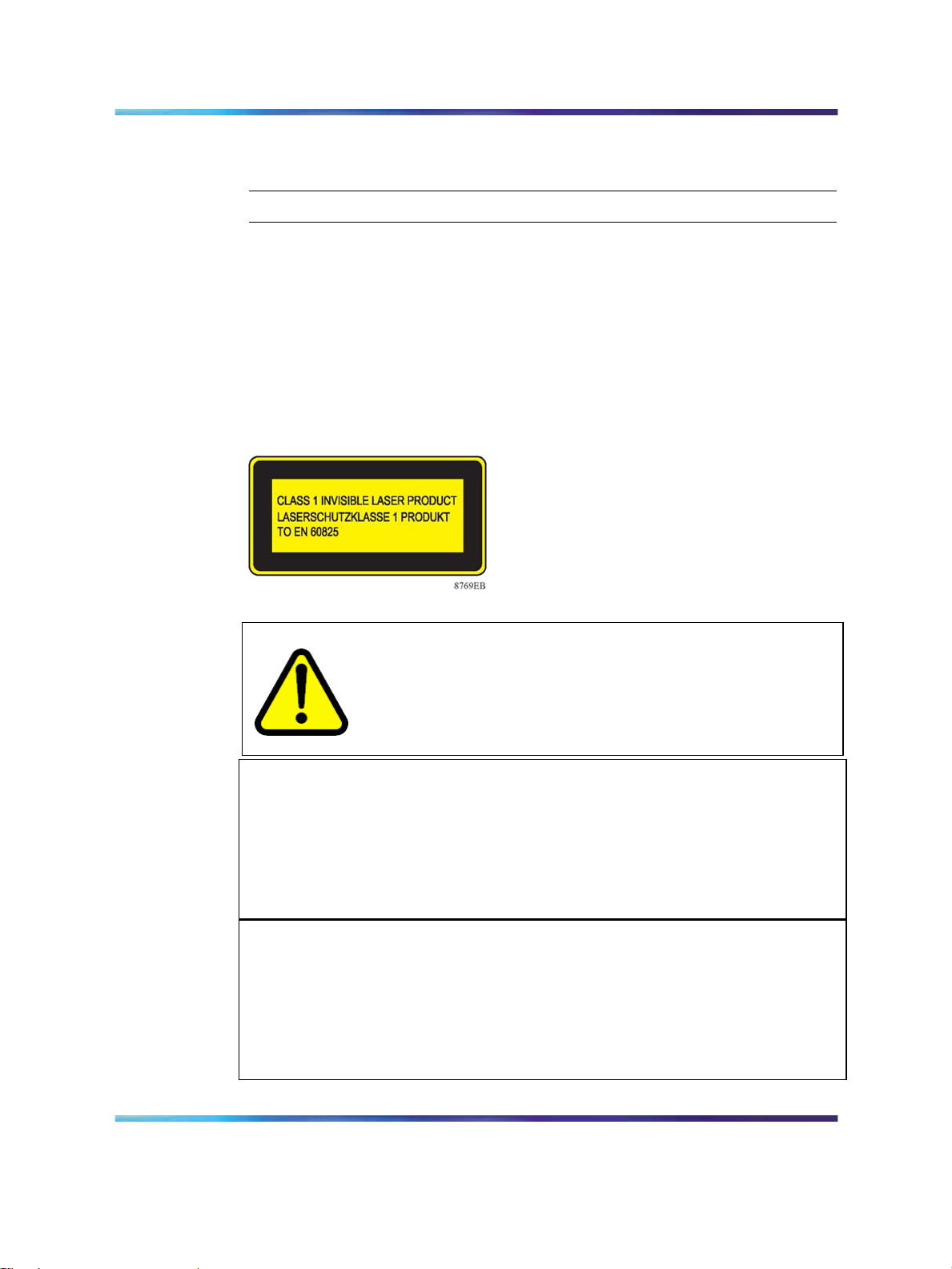
The products described in this guide meet requirements of:
IEC 60950 3rd edition
CSA 22.2 No. 60950 3rd edition
UL 60950 3rd edition
EN60950 3rd edition
EN60825-1, +A11, +A2
WARNING
Fiber optic equipment can emit laser or infrared light that can
injure your eyes. Never look into an optical fiber or connector port.
Always assume that fiber optic cables are connected to a light
source.
ATTENTION
Vorsicht:
Glasfaserkomponenten können Laserlicht bzw. Infrarotlicht abstrahlen, wodurch
Ihre Augen geschädigt werden können. Schauen Sie niemals in einen
Glasfaser-LWL oder ein Anschluβteil. Gehen Sie stets davon aus, daβ das
Glasfaserkabel an eine Lichtquelle angeschlossen ist.
ATTENTION
Avertissement:
L’équipement à fibre optique peut émettre des rayons laser ou infrarouges qui
risquent d’entraîner des lesions oculaires. Ne jamais regarder dans le port d’un
connecteur ou d’un câble à fibre optique. Toujours supposer que les câbles à
fibre optique sont raccordés à une source lumineuse.
Installation — SFP, XFP, GBIC, and OADM Hardware Components
Copyright © 2008, Nortel Networks
.
Nortel Metro Ethernet Routing Switch 8600
NN46220-301 01.01 Standard
5.0 1 May 2008
Page 17
Electromagnetic interference compliance 17
ATTENTION
Advertencia:
Los equipos de fibra óptica pueden emitir radiaciones de láser o infrarrojas que
pueden dañar los ojos. No mire nunca en el interior de una fibra óptica ni de
un puerto de conexión. Suponga siempre que los cables de fibra óptica están
conectados a una fuente luminosa.
ATTENTION
Avvertenza:
Le apparecchiature a fibre ottiche emettono raggi laser o infrarossi che possono
risultare dannosi per gli occhi. Non guardare mai direttamente le fibre ottiche o le
porte di collegamento. Tenere in considerazione il fatto che i cavi a fibre ottiche
sono collegati a una sorgente luminosa.
CAUTION
Only qualified technicians should install this equipment.
Place all printed circuit boards on an antistatic mat until you are
ready to install them. If you do not have an antistatic mat, wear
a discharge leash to free yourself of static before touching any of
the printed circuit boards, or free yourself of static by touching a
grounded metal object before you handle a printed circuit board.
Electromagnetic interference compliance
WARNING
Use of controls or adjustments, or performance of procedures
other than those specified herein can result in hazardous radiation
exposure.
The products described in this guide meet requirements of:
FCC Part 15, Subparts A and B, Class A
EN55022: 1998/CISPR22:1997), Class A
General License VDE 0871, Class B
(AmtsblVfg No. 243/1991, Vfg 46/1992) VCCI Class A ITE
EN55024:1998/CISPR24:1997
Installation — SFP, XFP, GBIC, and OADM Hardware Components
Copyright © 2008, Nortel Networks
.
Nortel Metro Ethernet Routing Switch 8600
NN46220-301 01.01 Standard
5.0 1 May 2008
Page 18
18 Safety and regulatory information
Federal Communications Commission (FCC) Compliance Notice: Radio
Frequency Notice
This equipment has been tested and found to comply with the limits for a
Class A digital device, pursuant to Part 15 of the FCC rules. These limits
are designed to provide reasonable protection against harmful interference
when the equipment is operated in a commercial environment. This
equipment generates, uses, and can radiate radio frequency energy. If
it is not installed and used in accordance with the instruction manual, it
may cause harmful interference to radio communications. Operation of
this equipment in a residential area is likely to cause harmful interference,
in which case users will be required to take whatever measures may be
necessary to correct the interference at their own expense.
European EN 55 022 statement
This is to certify that the Nortel Networks optical routing system is
shielded against the generation of radio interference in accordance with
the application of Council Directive 89/336/EEC, Article 4a. Conformity is
declared by the application of EN 55 022 Class A (CISPR 22).
CAUTION
This is a Class A product. In a domestic environment, this product
may cause radio interference, in which case, the user may be
required to take appropriate measures.
ATTENTION
Achtung:
Dieses ist ein Gerät der Funkstörgrenzwertklasse A. In Wohnbereichen können
bei Betrieb dieses Gerätes Rundfunkstörungen auftreten, in welchen Fällen der
Benutzer für entsprechende Gegenmaβnahmen verantwortlich ist.
ATTENTION
Ceci est un produit de Classe A. Dans un environnement domestique, ce produit
risque de créer des interférences radioélectriques, il appartiendra alors à
l’utilisateur de prendre les mesures spécifiques appropriées.
European EC Declaration of Conformity
These product conforms to the provisions of the R&TTE Directive
1999/5/EC.
Installation — SFP, XFP, GBIC, and OADM Hardware Components
Copyright © 2008, Nortel Networks
.
Nortel Metro Ethernet Routing Switch 8600
NN46220-301 01.01 Standard
5.0 1 May 2008
Page 19

Electromagnetic interference compliance 19
Japan/Nippon Voluntary Control Council for Interference (VCCI)
statement
Taiwan Bureau of Standards, Metrology and Inspection (BSMI) Statement
Canadian Department of Communications Radio Interference
Regulations
This digital apparatus does not exceed the Class A limits for radio-noise
emissions from digital apparatus as set out in the Radio Interference
Regulations of the Canadian Department of Communications.
Règlement sur le brouillage radioélectrique du ministère des
Communications
Cet appareil numérique respecte les limites de bruits radioélectriques visant
les appareils numériques de classe A prescrites dans le Règlement sur le
brouillage radioélectrique du ministère des Communications du Canada.
Canadian Department of Communications Radio Interference
Regulations
This digital apparatus does not exceed the Class B limits for radio-noise
emissions from digital apparatus as set out in the Radio Interference
Regulations of the Canadian Department of Communications.
Règlement sur le brouillage radioélectrique du ministère des
Communications
Cet appareil numérique respecte les limites de bruits radioélectriques visant
les appareils numériques de classe B prescrites dans le Règlement sur le
brouillage radioélectrique du ministère des Communications du Canada.
Installation — SFP, XFP, GBIC, and OADM Hardware Components
Copyright © 2008, Nortel Networks
.
Nortel Metro Ethernet Routing Switch 8600
NN46220-301 01.01 Standard
5.0 1 May 2008
Page 20

20 Safety and regulatory information
Installation — SFP, XFP, GBIC, and OADM Hardware Components
Copyright © 2008, Nortel Networks
.
Nortel Metro Ethernet Routing Switch 8600
NN46220-301 01.01 Standard
5.0 1 May 2008
Page 21

Small form factor pluggable transceivers
This section describes how to select and install small form factor pluggable
(SFP) transceivers.
Use an SFP to interface a device motherboard to a fiber optic or unshielded
twisted pair network cable. The SFPs described in this section provide
Ethernet at 1 gigabit per second (Gbit/s).
Navigation
•
"Selecting an SFP" (page 21)
•
"Installing an SFP" (page 25)
•
"Removing an SFP" (page 28)
•
"SFP specifications" (page 45)
21
Selecting an SFP
Use an SFP transceiver to interface a device motherboard to a fiber optic or
unshielded twisted pair network cable. Select the appropriate transceiver to
provide the required reach.
Procedure steps
Step Action
1
2
Installation — SFP, XFP, GBIC, and OADM Hardware Components
Copyright © 2008, Nortel Networks
.
Determine the required reach.
Depending on the product, SFPs are available for cable distances
of up to 100 meters (m), 550 m, 10 kilometers (km), 40 km, 70 km,
and 120 km.
Determine the required media and connector type.
Fiber optic cable is required for any reach over 100 m.
Possible media include CAT5, single mode fiber, and multimode
fiber. Possible connectors include LC, MT-RJ, and RJ-45.
Nortel Metro Ethernet Routing Switch 8600
NN46220-301 01.01 Standard
5.0 1 May 2008
Page 22
22 Small form factor pluggable transceivers
3
If the media is optical fiber, determine any wavelength restrictions or
requirements.
To expand available bandwidth on a common optical fiber, use
CWDM SFPs.
4 Determine if digital diagnostic monitoring (DDM) is required.
Not all SFPs or products support DDM.
5
Use the following job aids to determine the appropriate SFP for your
application.
SFPs
Procedure job aid: SFPs and common applications
The following table describes the reach provided by various SFPs. This
table is informational only—not all Nortel ethernet switching and routing
products support all the SFPs listed here.
Table 2 SFPs and common applications
—End—
SFP model Common application
1000BASE-T Lowest-cost Gigabit Ethernet solution. Up to 100 m reach over Category 5
(CAT5) unshielded twisted pair (UTP).
1000BASE-SX Well-suited for campus local area networks (LAN) and intrabuilding links.
Up to 275 or 550 m reach (fiber-dependent) over a fiber pair.
1000BASE-LX Up to 10 km reach over a single mode fiber (SMF) pair. Up to 550 m reach
over a multimode fiber (MMF) pair.
1000BASE-XD Up to 40 km reach over a single mode fiber pair.
1000BASE-ZX Up to 70 km reach over a single mode fiber pair.
1000BASE-BX Up to 10 km or 40 km reach. Bidirectional over one single mode fiber.
1000BASE-EX Up to 120 km reach over a single mode fiber pair.
Procedure job aid: SFP models without DDI support
SFPs are hot-swappable input/output enhancement components designed
for use with Nortel products to allow Gigabit Ethernet ports to link with other
Gigabit Ethernet ports over various media types.
The SFPs described in this section do not have Digital Diagnostic Interface
capability, and are RoHS -E5 compliant.
Installation — SFP, XFP, GBIC, and OADM Hardware Components
Copyright © 2008, Nortel Networks
.
Nortel Metro Ethernet Routing Switch 8600
NN46220-301 01.01 Standard
5.0 1 May 2008
Page 23
CWDM SFPS are also supported. CWDM technology consolidates
multiple optical channels on a common optical fiber. CWDM uses multiple
wavelengths to expand available bandwidth.
CWDM SFPs are designed to support high speed data communications
for Metropolitan Area Networks (MANs). The system uses a grid of eight
CWDM optical wavelengths in both ring and point-to-point configurations.
All components are color-coded by wavelength.
ATTENTION
The attainable cable length can vary depending on the quality of the fiber optic
cable used.
Table 3 SFP models without DDI support
Model and connector Product number Description
Selecting an SFP 23
1000BASE-SX (LC) AA1419013-E5
1000BASE-SX (MT-RJ) AA1419014-E5
1000BASE-LX (LC) AA1419015-E5 1310 nm, up to 10 km
1000BASE-XD CWDM (LC)
(see Note 1)
1000BASE-ZX CWDM (LC)
(see Note 2)
Note 1: Use the E6 version (AA1419053-E6 to AA1419060-E6). See Table 4 "SFP models with DDI
capability" (page 24). The E6 version addresses a latching issue with the E5 version.
Note 2: Use the E6 version (AA1419061-E6 to AA1419068-E6). See Table 4 "SFP models with DDI
capability" (page 24). The E6 version addresses a latching issue with the E5 version.
AA1419025-E5 to
AA1419032-E5
AA1419033-E5 to
AA1419040-E5
850 nm, up to 275 or 550 m
850 nm, up to 275 or 550 m
1470 nm to 1610 nm, up to 40 km
1470 nm to 1610 nm, up to 70 km
For specifications for these SFPs, see "SFP specifications" (page 45).
Procedure job aid: SFP models with DDI support
Digital Diagnostic Monitoring (DDM) allows the Metro Ethernet Routing
Switch 8600 to monitor SFP laser operating characteristics. Metro Ethernet
Routing Switch 8600 support for Digital Diagnostic Interfaces (DDI—an
interface that supports DDM) involves data collection and alarm and warning
monitoring. Static data collection includes the SFP vendor information, DDI
support information, and DDI alarm and warning threshold values. Dynamic
data collection includes temperature, supply voltage, laser bias current,
transmit power, and receive power. DDM works at any time during active
laser operation without affecting data traffic.
The warning and alarm status bits are only checked during initialization
and during requests for dynamic data. If an alarm or warning is asserted
or cleared, a message is logged and a trap is generated. DDM warning
Installation — SFP, XFP, GBIC, and OADM Hardware Components
Copyright © 2008, Nortel Networks
.
Nortel Metro Ethernet Routing Switch 8600
NN46220-301 01.01 Standard
5.0 1 May 2008
Page 24
24 Small form factor pluggable transceivers
and alarm messages are mapped into WARNING and FATAL message
categories for system logging purposes. If an alarm or warning is generated,
the software does not automatically shut down the port.
CWDM SFPs are also supported. CWDM SFPs are designed to support
high-speed data communications. A CWDM system uses a grid of
wavelengths to provide multiple channels for both ring and point-to-point
configurations. All components are color-coded by wavelength.
Any DDM SFP can be used in any Metro Ethernet Services Unit 1800 or
1850 device or Metro Ethernet Routing Switch 8600 module that supports
SFPs. The optical functions of the SFP are supported. Access to the DDI
information is only provided for:
•
Metro ESU 1850
•
Metro Ethernet Routing Switch 8600 modules 8630 and 8683
Access to DDI information is not supported for:
•
Metro ESU 1800
•
Metro Ethernet Routing Switch 8600 module 8668
The SFPs described in this section are all RoHS -E6 compliant.
For information about configuring DDM, see Nortel Metro Ethernet Routing
Switch 8600 Troubleshooting (NN46220-701).
The following table lists and describes the Nortel SFP models with DDI
capability. All the optical SFPs use LC connectors.
Table 4 SFP models with DDI capability
Model number and connector Product number Description
1000BASE-T (RJ-45) AA1419043-E6 CAT5 UTP, up to 100 m. Note that
because the 1000BASE-T device is
all electrical, there is no need for DDI
support.
1000BASE-SX AA1419048-E6
1000BASE-LX AA1419049-E6 1310 nm, up to 10 km
1000BASE-XD AA1419050-E6 1310 nm, up to 40 km
1000BASE-XD AA1419051-E6 1550 nm, up to 40 km
1000BASE-ZX AA1419052-E6 1550 nm, up to 70 km
1000BASE-XD CWDM
AA1419053-E6 to
AA1419060-E6
850 nm, up to 275 or 550 m
1470 nm to 1610 nm, up to 40 km
Installation — SFP, XFP, GBIC, and OADM Hardware Components
Copyright © 2008, Nortel Networks
.
Nortel Metro Ethernet Routing Switch 8600
NN46220-301 01.01 Standard
5.0 1 May 2008
Page 25
Model number and connector Product number Description
Installing an SFP 25
1000BASE-ZX CWDM
1000BASE CWDM NTK591LH
1000BASE-BX AA1419069-E6,
1000BASE-BX AA1419076-E6,
1000BASE-EX AA1419071-E6 1550 nm, up to 120 km
100-Base FX AA1419074-E6 1310 nm, MMF, up to 2 km
100-Base LX AA1419081-E5 1310 nm, SMF, up to 10 km
100-Base BX10-U AA1419082-E5 1310 nm, bidirectional upstream Tx, up
AA1419061-E6 to
AA1419068-E6
NTK591MH
NTK591NH
NTK591PH
NTK591QH
NTK591RH
NTK591SH
NTK591TH
AA1419070-E6
AA1419077-E6
1470 nm to 1610 nm, up to 70 km
1470 nm, up to 120 km
1490 nm, up to 120 km
1510 nm, up to 120 km
1530 nm, up to 120 km
1550 nm, up to 120 km
1570 nm, up to 120 km
1590 nm, up to 120 km
1610 nm, up to 120 km
Bidirectional 1310 nm and 1490 nm, up
to 10 km
Bidirectional 1310 nm and 1490 nm, up
to 40 km
to 10 km
100-Base BX10-D AA1419083-E5 1530 nm, bidirectional downstream Tx,
up to 10 km
100-Base ZX AA1419084-E5 1550 nm, 70 to 80 km
For specifications for these SFPs, see "SFP specifications" (page 45).
Installing an SFP
Install an SFP to provide an interface between the switch and the network
cable.
Installing an SFP takes about 3 minutes.
SFPs are installed face up in the top rowand face down in the bottom row in
modules or ESUs that are equipped with two rows of SFPs.
Prerequisites
•
Verify that the SFP is the correct model for your network configuration.
Installation — SFP, XFP, GBIC, and OADM Hardware Components
Copyright © 2008, Nortel Networks
.
Nortel Metro Ethernet Routing Switch 8600
NN46220-301 01.01 Standard
5.0 1 May 2008
Page 26
26 Small form factor pluggable transceivers
Procedure steps
CAUTION
SFPs are keyed to prevent incorrect insertion. If the SFP resists
pressure, do not force it; turn it over, and reinsert it.
Step Action
1 Remove the SFP from its protective packaging.
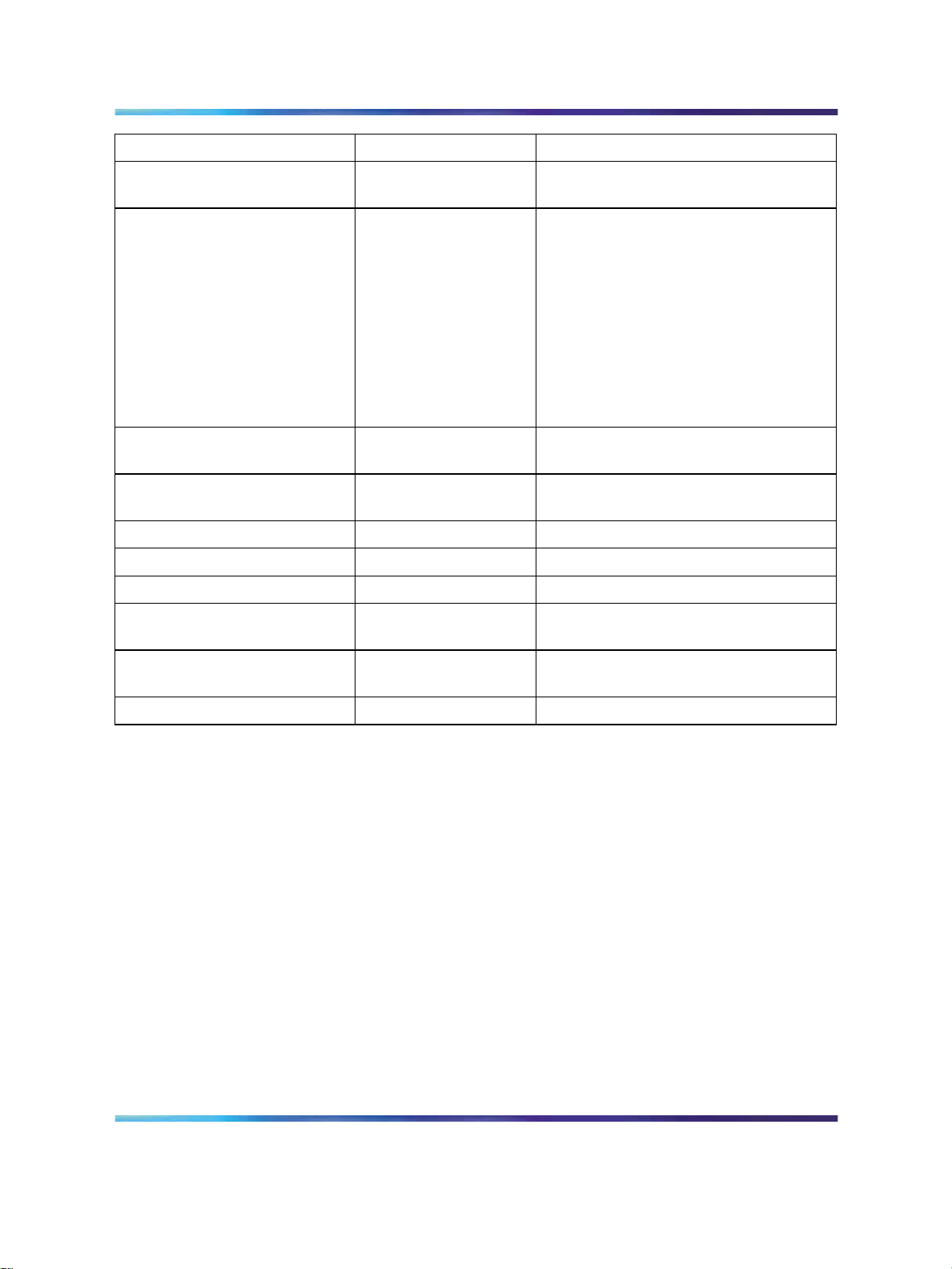
Figure 1 Installing an SFP
2
3
Grasp the SFP between your thumb and forefinger.
As shown in the following figure, insert the device into the slot on
the module.
Apply a light pressure to the device until it clicks and locks into
position.
4
Installation — SFP, XFP, GBIC, and OADM Hardware Components
Copyright © 2008, Nortel Networks
.
Remove the dust cover from the optical bore and insert the fiber
optic connector.
—End—
Nortel Metro Ethernet Routing Switch 8600
NN46220-301 01.01 Standard
5.0 1 May 2008
Page 27
Procedure job aid: locking and extractor mechanisms
Depending on the transceiver manufacturer, your SFP transceiver can have
various types of locking/extractor mechanisms.
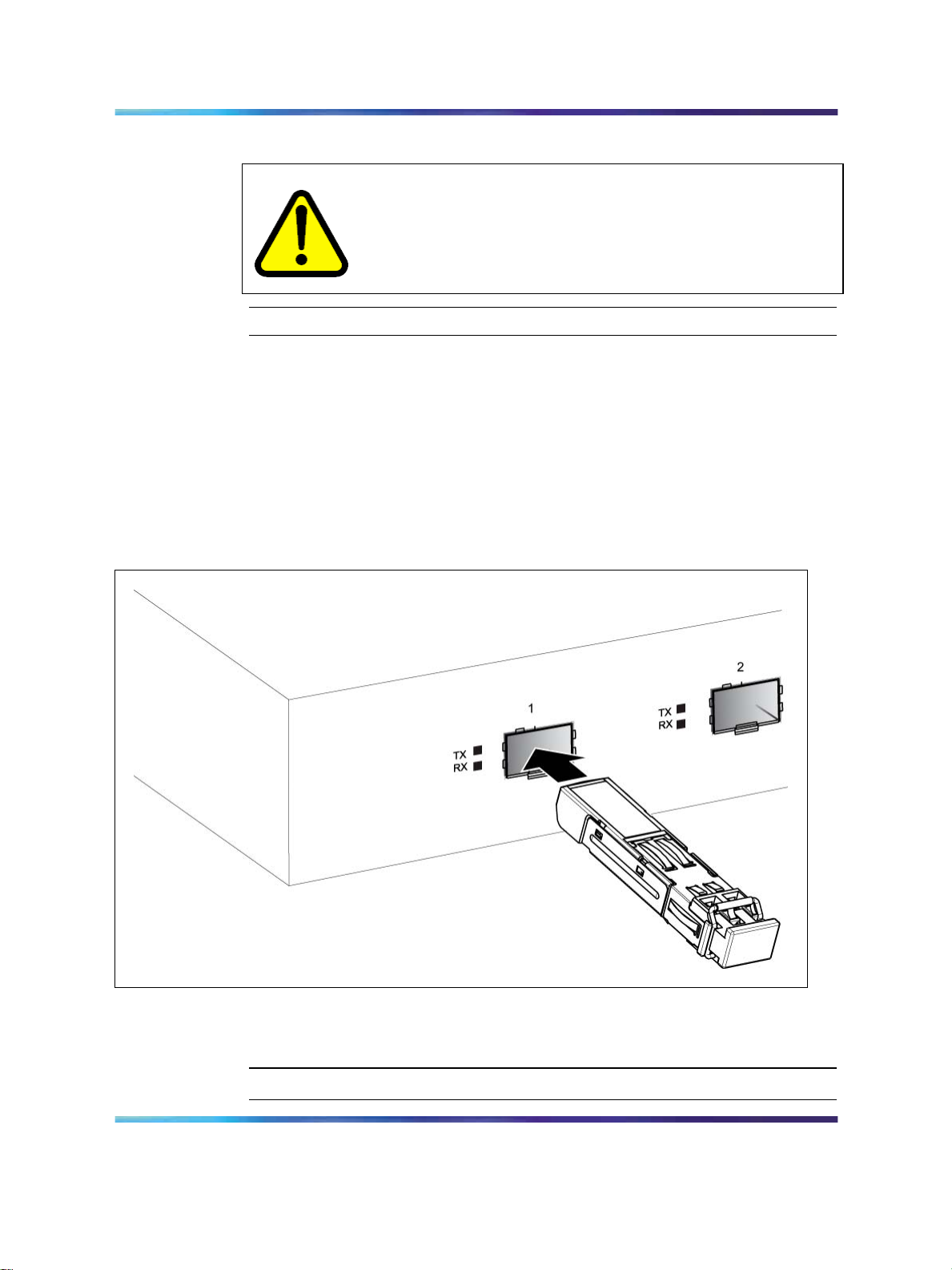
The following figures shows a typical mechanisms used on SFP
transceivers; other locking/extractor mechanisms exist, although they are
not shown here. In the figure Figure 2 "SFP with bail lock and extraction
mechanism" (page 27), the SFP still has the bore plug installed. Pull the
bail to release the device.
Figure 2 SFP with bail lock and extraction mechanism
Installing an SFP 27
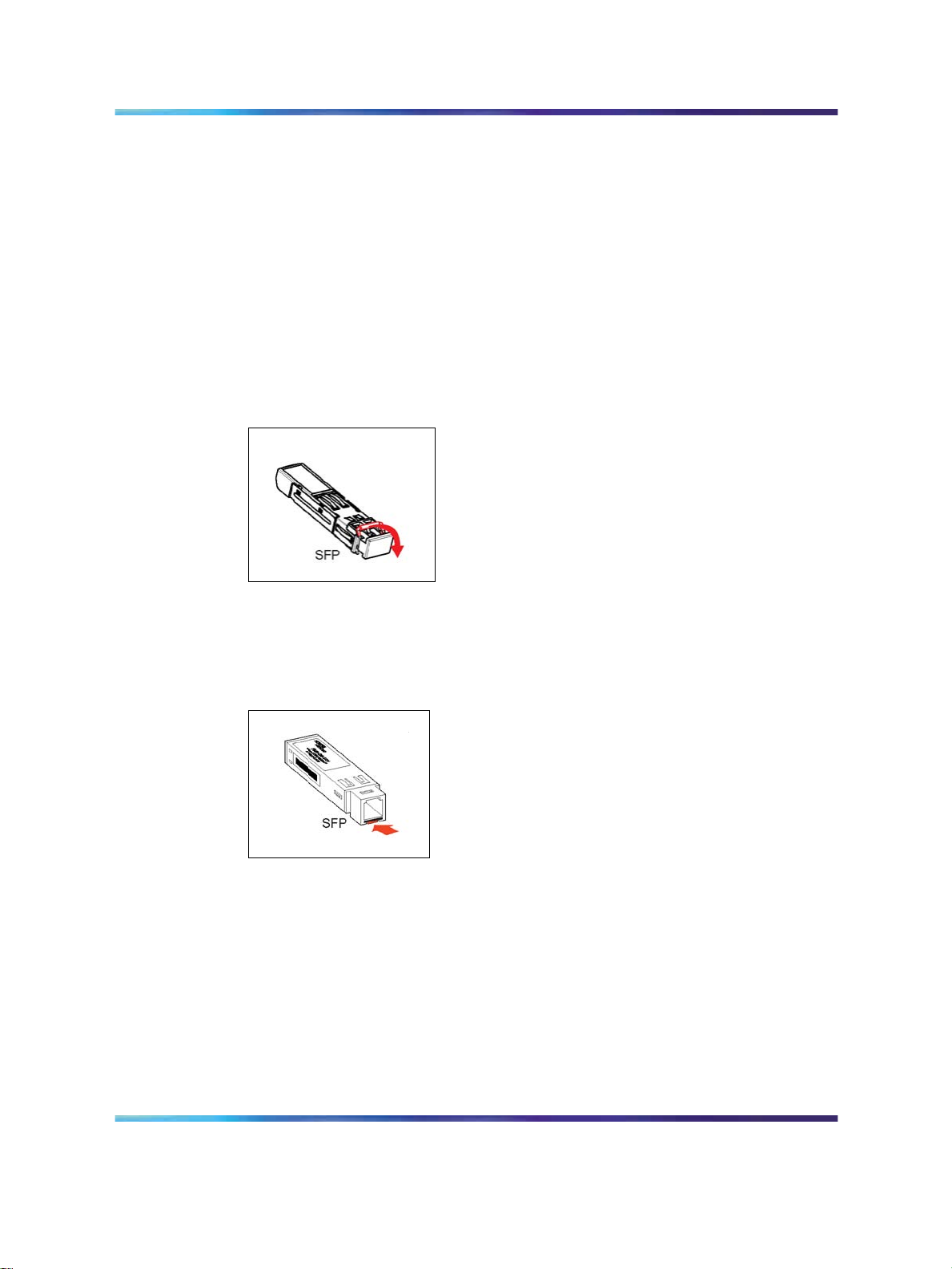
The following figure shows the 1000BASE-SX MT-RJ SFP. Push the tab
to release the device.
Figure 3 1000BASE-SX MT-RJ SFP extraction mechanism
The following figure shows the wrap-around latch-type extraction
mechanism. To remove the device, push the collar towards the module.
Installation — SFP, XFP, GBIC, and OADM Hardware Components
Copyright © 2008, Nortel Networks
.
Nortel Metro Ethernet Routing Switch 8600
NN46220-301 01.01 Standard
5.0 1 May 2008
Page 28
28 Small form factor pluggable transceivers
Figure 4 Wrap-around latch-type extraction mechanism
Removing an SFP
Remove an SFP to replace it or to commission it elsewhere.
Procedure steps
Step Action
1
2
3
4
5
Disconnect the network fiber cable from the SFP connector.
Affix dust covers over the fiber optic bore and connector.
Depending on your SFP model, to release the SFP, press the
locking/extractor mechanism.
Your SFP locking/extractor mechanism can be different than the
models shown.
Slide the SFP out of the module SFP slot.
If the SFP does not slide easily from the module slot, use a gentle
side-to-side rocking motion while firmly pulling the SFP from the slot.
Store the SFP in a safe place until needed.
ATTENTION
If you discard the SFP, be sure to dispose of it according to all national
laws and regulations.
Installation — SFP, XFP, GBIC, and OADM Hardware Components
Copyright © 2008, Nortel Networks
.
Nortel Metro Ethernet Routing Switch 8600
NN46220-301 01.01 Standard
5.0 1 May 2008
Page 29

—End—
Removing an SFP 29
Installation — SFP, XFP, GBIC, and OADM Hardware Components
Copyright © 2008, Nortel Networks
.
Nortel Metro Ethernet Routing Switch 8600
NN46220-301 01.01 Standard
5.0 1 May 2008
Page 30

30 Small form factor pluggable transceivers
Installation — SFP, XFP, GBIC, and OADM Hardware Components
Copyright © 2008, Nortel Networks
.
Nortel Metro Ethernet Routing Switch 8600
NN46220-301 01.01 Standard
5.0 1 May 2008
Page 31

Gigabit interface converters
ATTENTION
The Gigabit Interface Converters, GBIC (AA1419001 to AA1419004, AA1419017
to AA1419024, and AA1419041) are no longer supported
This section describes how to install and remove Gigabit Interface
Converters (GBIC), and lists the technical specifications for the supported
GBIC models.
Navigation
•
"Selecting a GBIC" (page 31)
•
"Installing a GBIC" (page 32)
•
"Removing a GBIC" (page 33)
•
"GBIC specifications" (page 63)
31
Selecting a GBIC
Use a GBIC to interface a device motherboard to a fiber optic or unshielded
twisted pair network cable. Select the appropriate transceiver to provide the
required reach.
Procedure steps
Step Action
1
2
Installation — SFP, XFP, GBIC, and OADM Hardware Components
Copyright © 2008, Nortel Networks
.
Determine the required reach.
GBICs are available for cable distances of up to 100 meters (m), 550
m, 10 kilometers (km), 40 km, 70 km, and 120 km.
Determine the required media and connector type.
Fiber optic cable is required for any reach over 100 m.
Depending on the product, possible media include CAT5, single
mode fiber, and multimode fiber. Possible connectors include SC
(subscriber connector) type and RJ-45.
Nortel Metro Ethernet Routing Switch 8600
NN46220-301 01.01 Standard
5.0 1 May 2008
Page 32

32 Gigabit interface converters
3
If the media is optical fiber, determine any wavelength restrictions or
requirements.
To expand available bandwidth on a common optical fiber, use
Coarse Wavelength Division Multiplexing (CWDM) GBICs.
4 Use the following job aids to determine the appropriate GBIC for
your application.
Procedure job aid: GBIC models
GBICs are hot-swappable input/output enhancement components designed
for use with Nortel products to allow Gigabit Ethernet ports to link with
other Gigabit Ethernet ports over various media types. The following table
describes supported GBICs. For specifications for these GBICs, see "GBIC
specifications" (page 63).
Attainable cable length can vary depending on the quality of the fiber optic cable
used.
—End—
ATTENTION
Table 5 GBIC models
Model and connector Product number Description
1000BASE-T (RJ-45) AA1419041-E5 CAT5 unshielded twisted pair (UTP), up to 100 m
1000BASE-SX (SC) AA1419001-E5 850 nanometers (nm), up to 275 or 550 m
1000BASE-LX (SC) AA1419002-E5 1310 nm, up to 10 km
1000BASE-XD (SC) AA1419003-E5 1550 nm, up to 50 km
1000BASE-ZX (SC) AA1419004-E5 1550 nm, up to 70 km
1000BASE-EX CWDM
(SC)
AA1419017-E5 to
AA1419024-E5
1470 nm to 1610 nm, up to 120 km
Installing a GBIC
Install a GBIC to complete the transmission path.
Installing a GBIC takes about 3 minutes.
Prerequisites
•
Verify that the GBIC is the correct model for your network configuration.
Installation — SFP, XFP, GBIC, and OADM Hardware Components
Copyright © 2008, Nortel Networks
.
Nortel Metro Ethernet Routing Switch 8600
NN46220-301 01.01 Standard
5.0 1 May 2008
Page 33

Procedure steps
Step Action
1 Remove the GBIC from its protective packaging.
Removing a GBIC 33
CAUTION
GBICs are keyed to prevent incorrect insertion. If the GBIC resists
pressure, do not force it; turn it over, and reinsert it.
2
3
Grasp the GBIC between your thumb and forefinger.
Insert the GBIC into the slot on the front panel of the Gigabit
Ethernet switching module.
Figure 5 Inserting a GBIC
4
Remove the dust cover and insert the fiber optic connector.
—End—
Removing a GBIC
Remove a GBIC to replace it or to commission it elsewhere.
Procedure steps
Step Action
1
2
Installation — SFP, XFP, GBIC, and OADM Hardware Components
Copyright © 2008, Nortel Networks
.
Disconnect the network fiber cable from the GBIC connector.
Attach a dust cover over the fiber optic bore.
Nortel Metro Ethernet Routing Switch 8600
NN46220-301 01.01 Standard
5.0 1 May 2008
Page 34

34 Gigabit interface converters
3
Depending on your GBIC model, grasp the extraction tabs located
on either side of the GBIC with your thumb and forefinger, or lift the
extractor handle attached to the GBIC.
Figure 6 GBIC models
4
Slide the GBIC out of the Gigabit Ethernet module slot.
If the GBIC does not slide easily from the module slot, use a gentle
side-to-side rocking motion while firmly pulling the GBIC from the
slot.
5
Store the GBIC in a safe place until needed.
ATTENTION
If you discard the GBIC, be sure to dispose of it according to all national
laws and regulations.
—End—
ATTENTION
When you contact a Nortel service representative for troubleshooting purposes,
you must have the following information available:
•
Nortel serial number
•
Manufacturer’s code
•
Interface type
•
GBIC part number
Installation — SFP, XFP, GBIC, and OADM Hardware Components
Copyright © 2008, Nortel Networks
.
Nortel Metro Ethernet Routing Switch 8600
NN46220-301 01.01 Standard
5.0 1 May 2008
Page 35

10 Gigabit small form factor pluggable transceivers
This section describes how to install and remove 10 Gigabit Small Form
Factor Pluggable (XFP) transceivers, and lists some technical specifications
for the supported XFP models.
ATTENTION
Nortel recommends that you only use Nortel qualified XFPs. If you do choose
to use other vendor XFPs, be aware that Nortel does not support the use of
other XFPs.
Navigation
•
"Selecting an XFP" (page 35)
•
"Installing an XFP" (page 37)
• "Removing an XFP" (page 39)
35
Selecting an XFP
Use an XFP transceivers to interface a device motherboard to a fiber optic
cable. Select the appropriate transceiver to provide the required reach.
Procedure steps
Step Action
1
2
3
Installation — SFP, XFP, GBIC, and OADM Hardware Components
Copyright © 2008, Nortel Networks
.
Determine the required reach.
XFPs are available for cable distances of up to 300 meters (m), 10
kilometers (km), 40 km, and 80 km.
Determine any wavelength restrictions or requirements.
Use the following job aids to determine the appropriate XFP for your
application.
—End—
Nortel Metro Ethernet Routing Switch 8600
NN46220-301 01.01 Standard
5.0 1 May 2008
Page 36

36 10 Gigabit small form factor pluggable transceivers
Procedure job aid: XFP models
XFPs are hot-swappable input/output enhancement components designed
for use with Nortel products to allow 10 Gigabit Ethernet ports to link with
other 10 Gigabit Ethernet ports. Digital diagnostic monitoring (DDM) allows
real-time access to device operating parameters. All XFPs come with DDM
capability.
All Nortel XFPs use LC connectors to provide precision keying, low interface
losses, and space savings.
The following table lists and describes the Nortel XFP models. For
specifications for these XFPs, see "XFP specifications" (page 73).
ATTENTION
You can configure the XFP to operate in either LAN or WAN mode, depending
on the module (8683XLR is a LAN-only module, and 8683XZR is a LAN/ WAN
module). Model numbers ending in R denote a LAN interface; model numbers
ending in W denote a WAN interface.
CAUTION
Nortel recommends that you install only one 10GBASE-ZR/ZW
XFP per module due to cooling limitations on the 8683XLR and
8683XZR modules. Nortel further recommends the installation of
the XFP only in port 1. You can install a 10GBASE-SR, -LR/LW, or
-ER/EW in one or both of the remaining ports.
Table 6 XFP models
Model number Product number Description
10GBASE-SR AA1403005-E5 850 nanometers (nm). The range is up to:
•
22 m using 62.5 micrometer (µm), 160
megaHertz times km (MHz-km) MMF
• 33 m using 62.5 µm, 200 MHz-km MMF
•
66 m using 62.5 µm, 500 MHz-km MMF
•
82 m using 50 µm, 500 MHz-km MMF
•
300 m using 50 µm, 2000 MHz-km MMF
10GBASE-LR/LW AA1403001-E5 1310 nm SMF. The range is up to 10 km.
10GBASE-ER/EW AA1403003-E5 1550 nm SMF. The range is up to 40 km.
10GBASE-ZR/ZW AA1403006-E5 1550 nm SMF. The range is up to 80 km.
Installation — SFP, XFP, GBIC, and OADM Hardware Components
Copyright © 2008, Nortel Networks
.
Nortel Metro Ethernet Routing Switch 8600
NN46220-301 01.01 Standard
5.0 1 May 2008
Page 37

Model number Product number Description
10GBASE DWDM
NTK587AY-E5
1537.40
Installing an XFP 37
NTK587BA-E5
NTK587BC-E5
NTK587BE-E5
NTK587BG-E5
NTK587BJ-E5
NTK587BL-E5
NTK587BN-E5
NTK587BQ-E5
NTK587BS-E5
NTK587BU-E5
Note: Due to hexidecimal to decimal rounding, and vice-versa, the wavelength numbers provided
by the XFP manufacturer and reported by the Metro Ethernet Routing Switch 8600 system may
vary slightly.
1538.19
1538.98
1539.77
1540.56
1541.35
1542.14
1542.94
1543.73
1544.53
1545.32
Installing an XFP
Install an XFP to provide a 10 Gigabit Ethernet interface between the switch
and other network devices.
Installing an XFP takes about 3 minutes.
Prerequisites
•
Verify that the XFP is the correct model for your network configuration.
Procedure steps
Installation — SFP, XFP, GBIC, and OADM Hardware Components
Copyright © 2008, Nortel Networks
.
CAUTION
Nortel recommends that you install only one 10GBASE-ZR/ZW
per module due to cooling limitations on the 8683XLR and
8683XZR modules. Nortel further recommends the installation of
the XFP only in port 1. You can install a 10GBASE-SR, -LR/LW, or
-ER/EW in one or both of the remaining ports.
CAUTION
XFPs are keyed to prevent incorrect insertion. If the XFP resists
pressure, do not force it; turn it over, and reinsert it.
Nortel Metro Ethernet Routing Switch 8600
NN46220-301 01.01 Standard
5.0 1 May 2008
Page 38

38 10 Gigabit small form factor pluggable transceivers
Step Action
1
2
3
Remove the XFP from its protective packaging.
Grasp the XFP between your thumb and forefinger.
Insert the XFP into the XFP slot on the module.
Apply a light pressure to the XFP until the device clicks and locks
into position in the module.
Figure 7 Installing an XFP
4
Remove the dust cover from the XFP optical bores and insert the
fiber optic cable.
Procedure job aid: locking and extractor mechanisms
Depending on the transceiver manufacturer, your XFP transceiver can have
various types of locking/extractor mechanisms.
The following figure shows a typical bail-type mechanism used on XFP
transceivers. Pull the bail down to release the device.
Installation — SFP, XFP, GBIC, and OADM Hardware Components
Copyright © 2008, Nortel Networks
.
—End—
Nortel Metro Ethernet Routing Switch 8600
NN46220-301 01.01 Standard
5.0 1 May 2008
Page 39

Figure 8 XFP with bail lock and extraction mechanism
Removing an XFP
Remove an XFP to replace it or to commission it elsewhere.
Procedure steps
Step Action
Removing an XFP 39
1
2
3
4
Disconnect the network fiber cable from the XFP connector.
Affix a dust cover over the optical connector.
Pull the bail mechanism on the XFP to release the XFP.
Slide the XFP out of the module XFP slot.
If the XFP does not slide easily from the module slot, use a gentle
side-to-side rocking motion while firmly pulling the XFP from the slot.
5
6
Replace the port dust cover or EMI plug in the module.
Store the XFP in a safe place until needed.
ATTENTION
If you discard the XFP, be sure to dispose of it according to all national
laws and regulations.
—End—
Installation — SFP, XFP, GBIC, and OADM Hardware Components
Copyright © 2008, Nortel Networks
.
Nortel Metro Ethernet Routing Switch 8600
NN46220-301 01.01 Standard
5.0 1 May 2008
Page 40

40 10 Gigabit small form factor pluggable transceivers
Installation — SFP, XFP, GBIC, and OADM Hardware Components
Copyright © 2008, Nortel Networks
.
Nortel Metro Ethernet Routing Switch 8600
NN46220-301 01.01 Standard
5.0 1 May 2008
Page 41

Optical multiplexers
The Nortel optical routing system supports high-speed data communications
in metropolitan area networks (MAN) by connecting Gigabit Ethernet ports
with fiber optic networks, and by combining multiple wavelengthson a single
fiber to expand available bandwidth.
Use multiplexers in optical routing systems to multiplex, add, or drop
wavelengths in optical networks.
Multiplexing equipment
An optical add/drop multiplexer (OADM) adds or drops one wavelength to
or from a fiber carrying multiple wavelengths. An optical multiplexer adds
or drops multiple wavelengths to or from a fiber.
The following table shows supported OADMs and OMUXs and the
corresponding wavelengths of operation.
41
Table 7 CWDM multiplexers
Description
1470 nm, Gray AA1402002-E5
1490 nm, Violet AA1402003-E5 AA1402009-E5 AA1402010-E5
1510 nm, Blue AA1402004-E5
1530 nm, Green AA1402005-E5 AA1402009-E5 AA1402010-E5
1550 nm, Yellow AA1402006-E5
1570 nm, Orange AA1402007-E5 AA1402009-E5 AA1402010-E5
1590 nm, Red AA1402008-E5
1610 nm, Brown AA1402011-E5 AA1402009-E5 AA1402010-E5
Copyright © 2008, Nortel Networks
.
CWDM OADM CWDM OMUX-4 CWDM OMUX-8
—
—
—
—
Nortel Metro Ethernet Routing Switch 8600
Installation — SFP, XFP, GBIC, and OADM Hardware Components
NN46220-301 01.01 Standard
5.0 1 May 2008
AA1402010-E5
AA1402010-E5
AA1402010-E5
AA1402010-E5
Page 42

42 Optical multiplexers
Installing the shelf
The optical routing system (OADM/OMUX) is mounted in an optical shelf
with connections at the front of the module. For user access to these
connections, a minimum of 36 inches (90 cm) of clearance is required. Keep
the area as dust-free as possible.
Step Action
1
Support the chassis so that all the mounting holes in the optical shelf
are aligned with the corresponding holes in the rack.
2
Attach two rack mounting bolts to each side of the rack.
3 Tighten all the bolts in rotation.
Installing a multiplexer
OADMs and OMUXs are passive devices that require no power for their
operation. You can inser them in the optical shelf and then connect them
into your network.
Step Action
1 Align the plug-in module with the optical shelf.
2
3
4
Gently push the plug-in module into the shelf cavity.
Tighten the captive screws.
Connect the network cables.
—End—
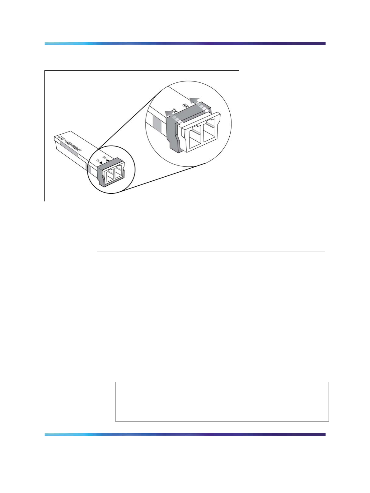
Connecting an OADM
Use this procedure to connect the OADM to SFP or GBICs and to east and
west backbone interfaces.
Step Action
1
2
Copyright © 2008, Nortel Networks
.
Insert the GBIC or SFPs into their respective modules. Make sure
that you have the correct GBIC or SFP for your network configuration
by matching the color of the label to the color of the connector label
on the OADM.
Clean all fiber optica connectors on the cabling.
Installation — SFP, XFP, GBIC, and OADM Hardware Components
—End—
Nortel Metro Ethernet Routing Switch 8600
NN46220-301 01.01 Standard
5.0 1 May 2008
Page 43
Connecting an OMUX 43
3
Connect the fiber optic cables from the GBIC or SFP transmit (Tx)
and receive (Rx) connectors to the OADM Equipment RX and TX
Equiment connectors.
4
Connect the west network backbone fiber optic cable to the OADM
west connector.
5
Connect the east backbone fiber optic cable to the OADM east
connector.
Procedure job aid: Optical add/drop multiplexers
The Nortel passive CWDM Optical Add/Drop Multiplexer (OADM) sends
and receives signals to and from CWDM GBICs and SFPs installed in
the switch. It adds or drops a specific wavelength from the optical fiber,
and allows all other wavelengths to pass through unaffected. The OADM
supports tow separate fiber pathways traveling in opposite directions (east
and west) so that the network remains viable even if the fiber is broken at
one point on the ring.
Connecting an OMUX
Use this procedure to connect the OMUX to SFP or GBICs and to eash and
west backbone interfaces.
—End—
Step Action
1
2
3
4
Installation — SFP, XFP, GBIC, and OADM Hardware Components
Copyright © 2008, Nortel Networks
.
WARNING
Multiplexing together several GICs or SFPs can produce a radiant
power level in the fiber that exceeds the class 1 laser limit. To
avoid damage to yourself or to the equipment, take care that you
follow proper connector safety and cleaning procedures.
Insert the GBICs or SFPs into their respective modules.
Clean all fiber optic connectors.
Connect the fiber optica cables from the GBIC/SFP TX and RX to
the OMUX Equipment RX and TX Equipment connectors. The GBIC
or SFP wavelength must match the OMUX equipment connector
wavelength. The TX of one device must always connect to the RX
of the next device.
Connect the network backbone east fiber optic cables to the east
(left) OMUX.
Nortel Metro Ethernet Routing Switch 8600
NN46220-301 01.01 Standard
5.0 1 May 2008
Page 44

44 Optical multiplexers
5
Connect the network backbone west fiber optic cables to the west
(right) OMUX.
Procedure job aid: optical multiplexer/demultiplexer
The Nortel passive optical multiplexer/demultiplexer (OMUX) sends and
receives signals to/from GBIC and SFP transceivers installed in the switch.
It multiplexes and demultiplexes four or eight CWDM wavelengths from a
two-fiber (east and west) circuit. Use the OMUX to create unidirectional
network traffic rings or point-to-point links.
Removing a multiplexer
OADMs and OMUXs require no power for their operation. You can remove
them from the optical shelf after disconnecting them from your network.
Step Action
1
2
Disconnect the network cabling from the multiplexer. Cover all
receptacles and connectors with dust caps.
Loosen the captive screws on both sides of the module.
—End—
3
4
to release the module, gently pull on both screws at the same time.
Slide the module out of the shelf.
—End—
Installation — SFP, XFP, GBIC, and OADM Hardware Components
Copyright © 2008, Nortel Networks
.
Nortel Metro Ethernet Routing Switch 8600
NN46220-301 01.01 Standard
5.0 1 May 2008
Page 45

SFP specifications
This section provides technical specifications for the supported small form
factor pluggable (SFP) models. Use this information to aid in proper network
design.
The specifications given in this section meet or exceed those specified in
the applicable IEEE standards, where they exist.
In these specifications, unless otherwise noted, receiver sensitivity is
defined as the minimum average input optical power for which the receiver
is guaranteed to meet the bit error rate (BER) of 10
Information about SFP and XFP power consumption has been added to
Installation—Modules (NN46220-306) in a section entitled "SFPs, XFPs, R
and RC modules, and power consumption".
Navigation
-12
45
.
•
"SFP labels" (page 46)
•
"General SFP specifications" (page 46)
•
"100BASE-FX SFP specifications" (page 47)
•
"100-Base LX SFP specifications" (page 48)
•
"100-Base BX10-U/D SFP specifications" (page 48)
•
"100-Base ZX SFP specifications" (page 49)
•
"1000BASE-T SFP specifications" (page 50)
•
"1000BASE-SX (LC) SFP specifications" (page 50)
•
"1000BASE-SX (MT-RJ) SFP specifications" (page 51)
•
"1000BASE-LX SFP specifications" (page 52)
•
"1000BASE-XD CWDM SFP specifications" (page 52)
•
"1000BASE-ZX CWDM SFP specifications" (page 53)
•
"1000BASE-SX DDI SFP specifications" (page 54)
Installation — SFP, XFP, GBIC, and OADM Hardware Components
Copyright © 2008, Nortel Networks
.
Nortel Metro Ethernet Routing Switch 8600
NN46220-301 01.01 Standard
5.0 1 May 2008
Page 46

46 SFP specifications
•
•
•
•
•
•
•
•
•
SFP labels
The Nortel label on a typical SFP contains a Nortel serial number, a bar
code, a manufacturer’s code, an interface type, and a part number.
Figure 9 SFP label
"1000BASE-LX DDI SFP specifications" (page 54)
"1000BASE-XD DDI 1310 nm SFP specifications" (page 55)
"1000BASE-XD DDI 1550 nm SFP specifications" (page 56)
"1000BASE-ZX DDI SFP specifications" (page 56)
"1000BASE-XD DDI CWDM SFP specifications" (page 57)
"1000BASE-ZX DDI CWDM SFP specifications" (page 58)
"1000Base CWDM SFP" (page 58)
"1000BASE-BX DDI SFP specifications" (page 59)
"1000BASE-EX DDI SFP specifications" (page 61)
General SFP specifications
The following table describes general SFP specifications.
Nortel Metro Ethernet Routing Switch 8600
Installation — SFP, XFP, GBIC, and OADM Hardware Components
NN46220-301 01.01 Standard
Copyright © 2008, Nortel Networks
.
5.0 1 May 2008
Page 47
100BASE-FX SFP specifications 47
Table 8
General SFP specifications
Parameter Description
Dimensions (H x W x D) 13.4 x 8.50 x 56.4 millimeters (mm)
0.53 x 0.33 x 2.22 inches (in.) unless otherwise
stated
Operating temperature -40 to 80C for RoHS - E6 models
0 to 60C for RoHS - E5 models
Storage temperature -40 to 85C
Maximum supply current 300 mA unless otherwise stated
Maximum power consumption 1.0 W unless otherwise stated
100BASE-FX SFP specifications
The 100BASE-FX SFP provides 100 Mbit/s Ethernet Carrier Sense Multiple
Access with Collision Detection (CSMA-CD) connectivity using multimode
optical fiber. The part number for this model is AA1419074-E6.
The following table describes the 100BASE-FX SFP specifications.
Table 9
100BASE-FX SFP specifications
Parameter
Specifications
Maximum electrical power consumption 1.5 W
Connectors Duplex LC
•
Cabling
Distance
62.5 µm MMF optic cable
•
50 µm MMF optic cable
•
Up to 2 km using 500 MHz-km MMF optic
cable
Wavelength
1310 nm
Link optical power budget 10 dB
Transmitter characteristics
Maximum launch power -14 dBm
Minimum launch power -23.5 to -20 dBm
Receiver characteristics
Receiver sensitivity 33.5 dBm
Maximum input power
—
Installation — SFP, XFP, GBIC, and OADM Hardware Components
Copyright © 2008, Nortel Networks
.
Nortel Metro Ethernet Routing Switch 8600
NN46220-301 01.01 Standard
5.0 1 May 2008
Page 48

48 SFP specifications
100-Base LX SFP specifications
The 100BASE-LX SFP provides 100 Mbit/s Ethernet Carrier Sense Multiple
Access with Collision Detection (CSMA-CD) connectivity using single mode
optical fiber. The part number for this model is AA1419081-E5.
The following table describes the 100BASE-LX SFP specifications.
Table 10
100-Base LX SFP specifications
Parameter
Maximum electrical power consumption 1.5 W
Connectors Duplex LC
Cabling 62.5 µm SMF optic cable
Distance Up to 10 km using 500 Mhz-km MMF optic cable
Wavelength
Link optical power budget 10 dB
Transmitter characteristics
Maximum launch power -14 dBm
Minimum launch power -23.5 to -20 dBm
Receiver characteristics
Receiver sensitivity -33.5 dBm
Maximum input power
Specifications
50 µm MMF optic cable
1310 nm
—
100-Base BX10-U/D SFP specifications
The 100BASE- BX 10-U (upstream) and 100BASE-BX 10-D (downstream)
bidirectional SFP provides 100 Mbit/s Ethernet Carrier Sense Multiple
Access with Collision Detection (CSMA-CD) connectivity. The part number
for the upstream model is AA1419082-E5. The part number for the
downstream model is AA1419083-E5.
The following table describes the 100BASE BX10-U/D SFP specifications.
Table 11
100-Base BX10-U/D SFP specifications
Parameter
Maximum electrical power consumption 1.5 W
Connectors Duplex LC
Cabling 62.5 µm SMF optic cable
Installation — SFP, XFP, GBIC, and OADM Hardware Components
Copyright © 2008, Nortel Networks
.
Nortel Metro Ethernet Routing Switch 8600
NN46220-301 01.01 Standard
5.0 1 May 2008
Specifications
50 µm MMF optic cable
Page 49

100-Base ZX SFP specifications 49
Distance Up to 10 km
Wavelength 1310 nm Tx (upstream)
1530 nm Tx (downstream)
Link optical power budget 10 dB
Transmitter characteristics
Maximum launch power -14 dBm
Minimum launch power 23.5 to -20 dBm
Receiver characteristics
Receiver sensitivity
Maximum input power
-33.5
—
100-Base ZX SFP specifications
The 100BASE-ZX SFP provides 100 Mbit/s Ethernet Carrier Sense Multiple
Access with Collision Detection (CSMA-CD) connectivity. The part number
for this model is AA1419084-E5.
The following table describes the 100BASE-ZX SFP specifications.
Table 12
100-Base ZX SFP specifications
Parameter
Maximum electrical power consumption 1.5 W
Connectors Duplex LC
Cabling 62.5 µm SMF optic cable
Distance 70 km to 80 km
Wavelength
Link optical power budget 10 dB
Specifications
50 µm MMF optic cable
1550 nm
Transmitter characteristics
Maximum launch power -14 dBm
Minimum launch power -23.5 to -20 dBm
Receiver characteristics
Receiver sensitivity -33.5 dBm
Maximum input power
Installation — SFP, XFP, GBIC, and OADM Hardware Components
Copyright © 2008, Nortel Networks
.
Nortel Metro Ethernet Routing Switch 8600
NN46220-301 01.01 Standard
5.0 1 May 2008
—
Page 50

50 SFP specifications
1000BASE-T SFP specifications
The 1000BASE-T SFP provides Gigabit Ethernet connectivity using a single
eight-pin RJ-45 connector. The 1000BASE-T SFP only operates at 1 gigabit
per second (1 Gbit/s) and does not support 100BASE-T or 10BASE-T
interfaces. The part number for this model is AA1419043-E6.
You must disable autonegotiation before operating the 1000BASE-T SFP.
By default, SFPs inserted into certain product-specific modules are set for
Autonegotiation = True.
The maximum current requirement of the SFP is 375 milliamperes (mA) at
5 volts (V).
The following table describes the 1000BASE-T SFP specifications.
Table 13
IEEE 802.3z 1000BASE-T SFP specifications
ATTENTION
Parameter
Standards IEEE 802.3z, IEEE 802.3ab
Connectors RJ-45
Cabling CAT5E or better UTP
Distance Up to 100 m
Specifications
1000BASE-SX (LC) SFP specifications
The 1000BASE-SX SFP provides 1000BASE-SX Gigabit Ethernet
connectivity at 850 nm using multimode optical fiber (MMF). This SFP
supports full-duplex operation only. The part number for this model is
AA1419013-E5.
ATTENTION
AA1419013-E5 continues to be supported. However, it is no longer orderable.
Order AA1419048-E6 as a replacement.
The following table describes standards, connectors, cabling, and distance
for the 1000BASE-SX SFP.
Table 14
IEEE 802.3z 1000BASE-SX (LC) SFP specifications
Parameter
Connectors Duplex LC
Installation — SFP, XFP, GBIC, and OADM Hardware Components
Copyright © 2008, Nortel Networks
.
Nortel Metro Ethernet Routing Switch 8600
NN46220-301 01.01 Standard
5.0 1 May 2008
Specifications
Page 51

1000BASE-SX (MT-RJ) SFP specifications 51
Parameter
Cabling
Distance
Specifications
•
62.5 µm MMF optic cable
•
50 µm MMF optic cable
•
up to 275 m using 62.5 µm MMF optic cable
•
up to 550 m using 50 µm MMF optic cable
Wavelength 850 nanometers (nm)
Link optical power budget 7.0 decibels (dB)
Transmitter characteristics
Launch power -10 to -4.0 decibels referenced to 1 milliwatt
(dBm)
Receiver characteristics
Receiver sensitivity -17 dBm
Maximum input power 0 dBm
1000BASE-SX (MT-RJ) SFP specifications
The 1000BASE-SX (MT-RJ type) SFP provides Gigabit Ethernet
connectivity using MT-RJ multimode fiber (MMF) connectors. The following
table describes standards, connectors, cabling, and distance for the
1000BASE-SX (MT-RJ type) SFP. The part number for this model is
AA1419014-E5.
Table 15
IEEE 802.3z 1000BASE-SX (MT-RJ) SFP specifications
Parameter
Specifications
Connectors Duplex MT-RJ
•
Cabling
Distance
Wavelength
62.5 µm MMF optic cable
•
50 µm MMF optic cable
• up to 275 m using 62.5 µm MMF optic cable
•
up to 550 m using 50 µm MMF optic cable
850 nm
Link optical power budget 7.0 dB
Transmitter characteristics
Launch power -10 to -4.0 dBm
Receiver characteristics
Receiver sensitivity -17 dBm
Maximum input power 0 dBm
Installation — SFP, XFP, GBIC, and OADM Hardware Components
Copyright © 2008, Nortel Networks
.
Nortel Metro Ethernet Routing Switch 8600
NN46220-301 01.01 Standard
5.0 1 May 2008
Page 52

52 SFP specifications
1000BASE-LX SFP specifications
The 1000BASE-LX SFP provides 1000BASE-LX Gigabit Ethernet
connectivity at 1310 nanometers (nm) using single mode (SMF) or
multimode optical fiber (MMF). The 1000BASE-LX SFP supports full-duplex
operation only. The part number for this model is AA1419015-E5.
AA1419015-E5 continues to be supported. However, it is no longer orderable.
Order AA1419049-E6 as its replacement.
The following table describes standards, connectors, cabling, and distance
for the 1000BASE-LX SFP.
Table 16
IEEE 802.3z 1000BASE-LX SFP specifications
ATTENTION
Parameter
Connectors Duplex LC
Cabling
Distance
Wavelength
Link optical power budget 10.5 dB
Transmitter characteristics
Launch power -9.5 to 3.0 dBm
Receiver characteristics
Receiver sensitivity -20 dBm
Maximum input power -3.0 dBm
Specifications
•
50 micrometer (µm) multimode fiber (MMF)
•
62.5 µm multimode fiber
• 9 µm single mode fiber (SMF)
•
Up to 550 meters (m) using MMF
•
Up to 10 kilometers (km) using SMF
1310 nm
1000BASE-XD CWDM SFP specifications
The 1000Base-XD SFPs provide CWDm Gigabit Ethernet connectivity
using single-mode fiber (SMF). These SFPs support full duplex operation
only. The part numbers of the 40 km models range from AA1419025-E5 to
AA1419032-E5.
AA1419025-E5 to AA1419032-E5 continue to be supported. However, they are no
longer orderable. Order AA1419053-E6 to AA1419060-E6 as their replacements.
Installation — SFP, XFP, GBIC, and OADM Hardware Components
Copyright © 2008, Nortel Networks
.
ATTENTION
Nortel Metro Ethernet Routing Switch 8600
NN46220-301 01.01 Standard
5.0 1 May 2008
Page 53

Table 17
1000BASE-XD CWDM (40 km) SFP specifications
1000BASE-ZX CWDM SFP specifications 53
Parameter
Connectors Duplex LC
Cabling SMF, 9 µm
Data rate 1.0 Gbit/s
Line rate (8B/10B code) 1.25 Gbit/s
Operating temperature range 0 to 60C
Link optical power budget 17 dB
Transmitter characteristics
Launch power -4.0 to 1.0 dBm
Receiver characteristics
Receiver sensitivity -21 dBm
Maximum input power -3.0 dBm
Specifications
ATTENTION
For the 40 km CWDM SFPs, a minimum attenuation of 4 dB must be present
between the transmitter and receiver. To avoid receiver saturation, you must insert
a minimum attenuation of 4 dB when you test the CWDM SFP in loopback mode,
or use short runs of fiber with no intermediate CWDM OADM or CWDM OMUX.
1000BASE-ZX CWDM SFP specifications
The 1000Base-Zx SFPs provide CWDM Gigabit Ethener connectivity using
single-mode fiber (SMF). These SFPs support full duplex operation only.
The part numbers of the 70 km models range from AA1419033-E5 to
AA1419040-E5.
ATTENTION
For the 70 km CWDM SFPs, a minimum attenuation of 10 dB must be present
between the transmitter and receiver.
ATTENTION
AA1419033-E5 to AA1419040-E5 continue to be supported. However, they are no
longer orderable. Order AA1419061-E6 to AA1419068-E6 as their replacements.
Table 18
1000BASE-ZX CWDM (70 km) SFP specifications
Parameter
Connectors Duplex LC
Installation — SFP, XFP, GBIC, and OADM Hardware Components
Copyright © 2008, Nortel Networks
.
Nortel Metro Ethernet Routing Switch 8600
NN46220-301 01.01 Standard
5.0 1 May 2008
Specifications
Page 54

54 SFP specifications
Parameter
Cabling SMF, 9 µm
Data rate 1.0 Gbit/s
Line rate (8B/10B code) 1.25 Gbit/s
Operating temperature range 0 to 60C
Link optical power budget 20 dB
Transmitter characteristics
Launch power -3.0 to 2.0 dBm
Receiver characteristics
Receiver sensitivity -23 dBm
Maximum input power -3.0 dBm
Specifications
1000BASE-SX DDI SFP specifications
The following table describes the 1000BASE-SX DDI SFP, which has a
reach of up to 550 m using 50 µm multimode fiber (MMF), and of 275 m
using 62.5 µm MMF. This SFP operates at 850 nm. The part number of
this SFP is AA1419048-E6.
Table 19
1000BASE-SX SFP DDI (550 m) specifications
Parameter
Maximum electrical power consumption 1 watt (W)
Connector Duplex LC
Cabling MMF
Data rate 1.0 Gbit/s
Line rate (8B/10B code) 1.25 Gbit/s
Link optical power budget 7.5 dB
Transmitter characteristics
Launch power -9.5 to -4.0 dBm
Receiver characteristics
Receiver sensitivity -17 dBm
Maximum receiver power 0 dBm
Specifications
1000BASE-LX DDI SFP specifications
This SFP can attain a reach of up to 10 km and operates at 1310 nm. The
part number of this SFP is AA1419049-E6.
Installation — SFP, XFP, GBIC, and OADM Hardware Components
Copyright © 2008, Nortel Networks
.
Nortel Metro Ethernet Routing Switch 8600
NN46220-301 01.01 Standard
5.0 1 May 2008
Page 55

Table 20
1000BASE-LX DDI SFP specifications
1000BASE-XD DDI 1310 nm SFP specifications 55
Parameter
Specifications
Maximum electrical power consumption 1.0 watt (W)
Connectors Duplex LC
Cabling SMF, 9 µm
Data rate 1.0 Gbit/s
Line rate (8B/10B code) 1.25 Gbit/s
Link optical power budget 9.5 dB
Transmitter characteristics
Launch power -9.5 to -3.0 dBm
Receiver characteristics
Receiver sensitivity -19.0 dBm
Maximum receiver power -3.0 dBm
1000BASE-XD DDI 1310 nm SFP specifications
The following table describes the 1000BASE-XD DDI SFP. This SFP
operates at 1310 nm and has a reach of up to 40 km. The part number is
AA1419050-E6.
Table 21
1000BASE-XD DDI 1310 nm SFP specifications
Parameter
Specifications
Maximum electrical power consumption 1.0 W
Connectors Duplex LC
Cabling SMF, 9 µm
Data rate 1.0 Gbit/s
Line rate (8B/10B) code 1.25 Gbit/s
Link optical power budget 18 dB
Transmitter characteristics
Launch power -4.5 to 0 dBm
Receiver characteristics
Receiver sensitivity -22.5 dBm
Maximum receiver power 0 dBm
Installation — SFP, XFP, GBIC, and OADM Hardware Components
Copyright © 2008, Nortel Networks
.
Nortel Metro Ethernet Routing Switch 8600
NN46220-301 01.01 Standard
5.0 1 May 2008
Page 56

56 SFP specifications
1000BASE-XD DDI 1550 nm SFP specifications
The following table describes the 1000BASE-XD DDI SFP. This SFP
operates at 1550 nm and has a reach of up to 40 km. The part number is
AA1419051-E6.
CAUTION
To preventdamage to the optical receiver, ensure that at least 3 dB
of attenuation is present between the transmit and receive ports.
Table 22
1000BASE-XD DDI 1550 nm SFP specifications
Parameter
Maximum electrical power consumption 1.0 W
Connectors Duplex LC
Cabling SMF, 9 µm
Data rate 1.0 Gbit/s
Line rate (8B/10B code) 1.25 Gbit/s
Link optical power budget 22 dB
Maximum dispersion power penalty 2 dB at 40 km
Transmitter characteristics
Launch power -2.0 to 3.0 dBm
Receiver characteristics
Receiver sensitivity -24 dBm
Maximum receiver power 0 dBm
Specification
1000BASE-ZX DDI SFP specifications
The following table describes the 1000BASE-ZX DDI SFP. This SFP
operates at 1550 nm and has a reach of up to 70 km. The part number is
AA1419052-E6.
Installation — SFP, XFP, GBIC, and OADM Hardware Components
Copyright © 2008, Nortel Networks
.
CAUTION
To preventdamage to the optical receiver, ensure that at least 5 dB
of attenuation is present between the transmit and receive ports.
Nortel Metro Ethernet Routing Switch 8600
NN46220-301 01.01 Standard
5.0 1 May 2008
Page 57

Table 23
1000BASE-ZX DDI 1550 nm SFP specifications
1000BASE-XD DDI CWDM SFP specifications 57
Parameter
Specifications
Maximum electrical power consumption 1.0 W
Connectors Duplex LC
Cabling SMF, 9 µm
Data rate 1.0 Gbit/s
Line rate (8B/10B code) 1.25 Gbit/s
Link optical power budget 24 dB
Maximum dispersion power penalty 2 dB at 70 km
Transmitter characteristics
Launch power 0 to 5 dBm
Receiver characteristics
Receiver sensitivity -24 dBm
Maximum receiver power -0 dBm
1000BASE-XD DDI CWDM SFP specifications
The followingtable describes specifications for 1000BASE-XD CWDM SFPs
numbered AA1419053-E6 to AA1419060-E6.
CAUTION
To preventdamage to the optical receiver, ensure that at least 4 dB
of attenuation is present between the transmit and receive ports.
Table 24
1000BASE-XD CWDM SFP DDI (40 km) specifications
Parameter
Maximum electrical power consumption 1.0 W
Connectors Duplex LC
Cabling SMF, 9 µm
Data rate 1.0 Gbit/s
Line rate (8B/10B code) 1.25 Gbit/s
Link optical power budget 17 dB
Maximum dispersion power penalty 1 dB at 40 km
Transmitter characteristics
Specifications
Installation — SFP, XFP, GBIC, and OADM Hardware Components
Copyright © 2008, Nortel Networks
.
Nortel Metro Ethernet Routing Switch 8600
NN46220-301 01.01 Standard
5.0 1 May 2008
Page 58

58 SFP specifications
Parameter
Launch power -4.0 to 1.0 dBm
Receiver characteristics
Receiver sensitivity -21 dBm
Maximum receiver power -3.0 dBm
Specifications
1000BASE-ZX DDI CWDM SFP specifications
The following table describes specifications for CWDM SFPs numbered
AA1419061-E6 to AA1419068-E6.
CAUTION
To preventdamage to the optical receiver, ensure that at least 8 dB
of attenuation is present between the transmit and receive ports.
Table 25
1000BASE-ZX CWDM SFP DDI (70 km) specifications
Parameter
Maximum electrical power consumption 1.0 W
Specifications
Connectors Duplex LC
Cabling SMF, 9 µm
Data rate 1.0 Gbit/s
Line rate (8B/10B code) 1.25 Gbit/s
Link optical power budget 24 dB
Maximum dispersion power penalty 2 dB at 70 km
Transmitter characteristics
Launch power 0 to 5.0 dBm
Receiver characteristics
Receiver sensitivity -24 dBm
Maximum receiver power -3.0 dBm
1000Base CWDM SFP
The following table describes specifications for CWDM SFPs numbered
NTK591LH/MH/NH/PH/QH/RH/SH/TH.
Installation — SFP, XFP, GBIC, and OADM Hardware Components
Copyright © 2008, Nortel Networks
.
Nortel Metro Ethernet Routing Switch 8600
NN46220-301 01.01 Standard
5.0 1 May 2008
Page 59
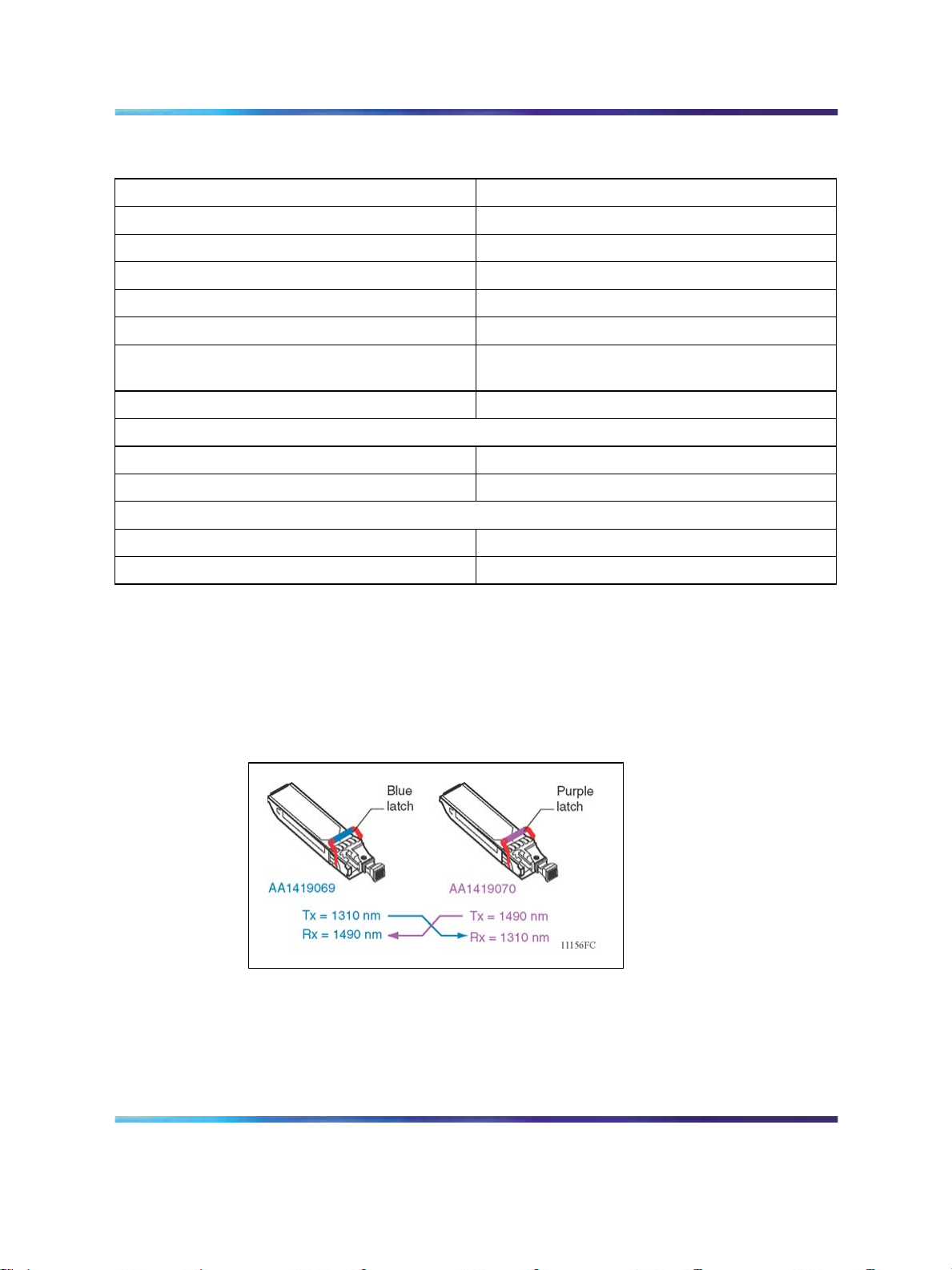
Table 26 1000BASE CWDM SFP
1000BASE-BX DDI SFP specifications 59
Parameter
Maximum electrical power consumption 1.0 W
Connectors Duplex LC
Cabling 9 µm SMF optic cable
Line rate (8B/10B code) 1.25 Gbit/s
Distance Up to 120 km
Wavelength (nominal central)
Link optical power budget 24 dB
Transmitter characteristics
Maximum launch power 5.0 dBm
Minimum launch power 1.0 dBm
Receiver characteristics
Receiver sensitivity -31.0 dBm
Maximum input power -5.0 dBm
Specifications
1471 nm, 1491 nm, 1511 nm, 1531 nm, 1551
nm, 1571 nm, 1591 nm, 1611 nm
1000BASE-BX DDI SFP specifications
The 1000BASE-BX bidirectional SFPs (part numbers AA1419069-E6,
AA1419070-E6, AA1419076-E6, and AA1419077-E6) provide Gigabit
Ethernet connectivity over a single fiber.
Figure 10 1000BASE-BX
As shown in the previous figure, the transmit (Tx) and receive (Rx) paths
share the same fiber by using two different wavelengths. One model
transmits at 1310 nm and receives at 1490 nm, while the mating model
transmits at 1490 nm and receives at 1310 nm. You can only connect a
mating pair.
Installation — SFP, XFP, GBIC, and OADM Hardware Components
Copyright © 2008, Nortel Networks
.
Nortel Metro Ethernet Routing Switch 8600
NN46220-301 01.01 Standard
5.0 1 May 2008
Page 60
60 SFP specifications
You can use 1000BASE-BX SFPs to double the number of your fiber links.
For example, if you have 20 installed fiber pairs with 20 conventional ports
connected, you can use 1000BASE-BX SFPs to expand to 40 ports, using
the same fiber.
The long wavelength optical transceivers used in these models provide
variable distance ranges using single mode fiber optic cabling.
The following table describes standards, connectors, cabling, and distances
for the 1000BASE-BX SFP.
CAUTION
Connect 1000BASE-BX SFP AA1419076-E6 to 1000BASE-BX
SFP AA1419077-E6 using a single mode fiber with at least 6 dB
of attenuation. Damage can result if insufficient attenuation is
provided or if the same 1000-BASE-BX SFPs are connected.
Table 27
IEEE 802.3ah 1000BASE-BX10 SFP specifications
Parameter
Specifications
Connectors Single-fiber LC
Data rate 1.0 Gbit/s
Line rate (8B/10B code) 1.25 Gbit/s
Distance AA1419069-E6 and AA1419070-E6: Up to 10 km
AA1419076-E6 and AA1419077-E6: Up to 40
km with SMF
Wavelength 1310 nm and 1490 nm
Link optical power budget AA1419069-E6 and AA1419070-E6: 11.0 dB
AA1419076-E6 and AA1419077-E6: 20.0 dB
Maximum transmitter and dispersion power
3.3 dB
penalty
Transmitter characteristics
Maximum launch power AA1419069-E6 and AA1419070-E6: -3.0 dBm
AA1419076-E6 and AA1419077-E6: 3.0 dBm
Minimum launch power AA1419069-E6 and AA1419070-E6: -9.0 dBm
AA1419076-E6 and AA1419077-E6: -3.0 dBm
Receiver characteristics
Maximum receiver sensitivity AA1419069-E6 and AA1419070-E6: -19.5 dBm
AA1419076-E6 and AA1419077-E6: -23.0 dBm
Maximum input power (maximum average
receive power)
Nortel Metro Ethernet Routing Switch 8600
Installation — SFP, XFP, GBIC, and OADM Hardware Components
NN46220-301 01.01 Standard
Copyright © 2008, Nortel Networks
.
-3.0 dBm
5.0 1 May 2008
Page 61
1000BASE-EX DDI SFP specifications
The following table describes the 1000BASE-EX DDI SFP. This SFP
operates at 1550 nm and has a reach of up to 120 km. The part number of
this SFP is AA1419071-E6.
CAUTION
To prevent damage to the optical receiver, ensure that at least 14
dB of attenuation is present between the transmit and receive
ports.
To attain the BER of 10
transmit and receive ports is 15 dB.
Table 28
1000BASE-EX DDI SFP specifications
1000BASE-EX DDI SFP specifications 61
-12
, the minimum attenuation between the
Parameter
Specifications
Maximum electrical power consumption 1.2 W
Connectors Duplex LC
Cabling SMF, 9 µm
Data rate 1.0 Gbit/s
Line rate (8B/10B code) 1.25 Gbit/s
Link optical power budget 30 dB
Maximum dispersion power penalty 2.0 dB at 120 km
Transmitter characteristics
Launch power 0 to 5.0 dBm
Receiver characteristics
Receiver sensitivity -30 dBm
Maximum receiver power -9.0 dBm
Installation — SFP, XFP, GBIC, and OADM Hardware Components
Copyright © 2008, Nortel Networks
.
Nortel Metro Ethernet Routing Switch 8600
NN46220-301 01.01 Standard
5.0 1 May 2008
Page 62

62 SFP specifications
Installation — SFP, XFP, GBIC, and OADM Hardware Components
Copyright © 2008, Nortel Networks
.
Nortel Metro Ethernet Routing Switch 8600
NN46220-301 01.01 Standard
5.0 1 May 2008
Page 63

GBIC specifications
The Gigabit Interface Converters, GBIC (AA1419001 to AA1419004, AA1419017
to AA1419024, and AA1419041) are no longer supported
This section provides technical specifications for the supported Gigabit
interface converter (GBIC) models. Use the specifications to help ensure
proper network operation.
Navigation
•
"GBIC labels" (page 63)
•
"General GBIC specifications" (page 64)
•
"1000BASE-T GBIC specifications" (page 64)
•
"1000BASE-SX GBIC specifications" (page 65)
63
ATTENTION
•
"1000BASE-LX GBIC specifications" (page 66)
•
"1000BASE-XD GBIC specifications" (page 68)
•
"1000BASE-ZX GBIC specifications" (page 68)
•
"1000BASE-EX CWDM GBIC specifications" (page 69)
GBIC labels
As shown in the following figure, the Nortel label on a typical GBIC contains
a Nortel serial number, a bar code, a manufacturer’s code, an interface
type, and a part number.
Installation — SFP, XFP, GBIC, and OADM Hardware Components
Copyright © 2008, Nortel Networks
.
Nortel Metro Ethernet Routing Switch 8600
NN46220-301 01.01 Standard
5.0 1 May 2008
Page 64
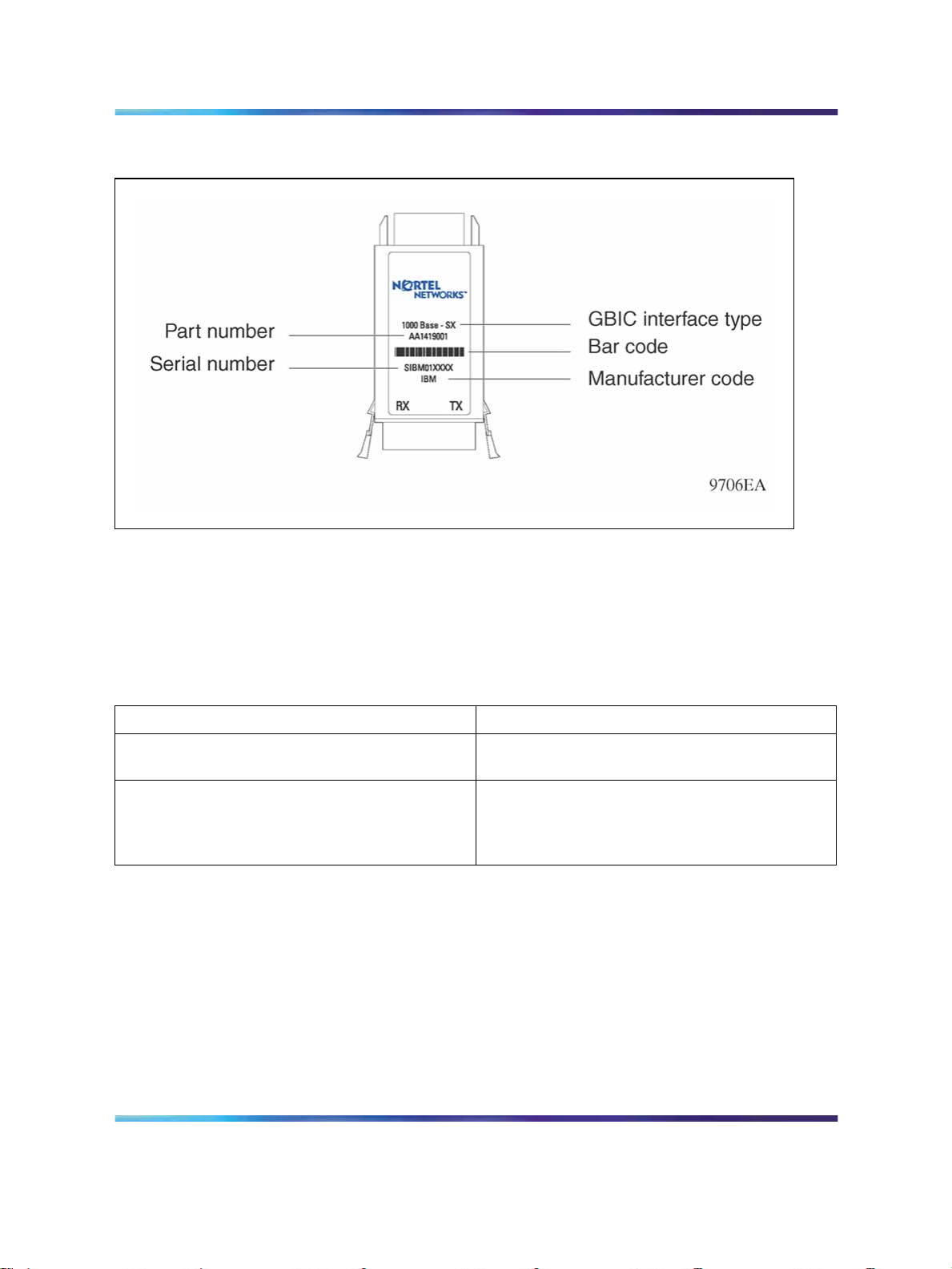
64 GBIC specifications
Figure 11 GBIC label
General GBIC specifications
The following table describes general GBIC specifications. GBIC ports
for both multimode (MMF) and single mode fiber (SMF) have SC-type
connectors and a minimum cable distance of 2 meters (m).
Table 29
GBIC physical specifications
Parameter
Dimensions (H x W x D) 0.39 x 1.2 x 2.6 inches (in.)
Connectors
Specifications
1.0 x 3.0 x 6.5 centimeters (cm)
•
Multimode: SC
• Single mode: SC
•
CAT5 RJ-45
1000BASE-T GBIC specifications
The 1000BASE-T GBIC provides Gigabit Ethernet connectivity using a
single eight-pin RJ-45 connector. The 1000BASE-T GBIC operates at 1
gigabit per second (Gbit/s) and does not support 100BASE-T or 10BASE-T
interfaces.
The part number of this GBIC is AA1419041-E5 for the Ethernet Routing
Switch and the Metro Ethernet Routing Switch.
Installation — SFP, XFP, GBIC, and OADM Hardware Components
Copyright © 2008, Nortel Networks
.
Nortel Metro Ethernet Routing Switch 8600
NN46220-301 01.01 Standard
5.0 1 May 2008
Page 65

You must disable autonegotiation before operating the 1000BASE-T GBIC.
By default, GBICs inserted into certain product-specific modules are set
for Autonegotiation = True. If autonegotiation does not work initially, Nortel
recommends that you reconfigure the switch to use a fixed-speed setting of 1000
Mbit/s, full-duplex, on both sides.
The maximum current requirement of the GBIC is 375 milliamperes (mA) at
5 volts (V).
The following table describes the 1000BASE-T GBIC.
Table 30
1000BASE-T GBIC specifications
1000BASE-SX GBIC specifications 65
ATTENTION
Parameter
Standards IEEE 802.3z, IEEE 802.3ab
Connectors RJ-45
Cabling CAT5 unshielded twisted pair (UTP)
Distance Up to 100 m
Specifications
1000BASE-SX GBIC specifications
The 1000BASE-SX GBIC provides 1000BASE-SX Gigabit Ethernet
connectivity using SC duplex multimode fiber connectors. This GBIC
supports full-duplex operation only. The part number of this GBIC is
AA1419001-E5.
The following table describes standards, connectors, cabling, and distance
for the 1000BASE-SX GBIC.
CAUTION
When multimode fiber is used in long-distance applications,
external, removable, mode-conditioning patch cords may be
required to preventdifferentialmode delay (DMD). Excessive DMD
can cause an increase in the bit error rate (BER). You can order
mode conditioning patch cords through Nortel:
Installation — SFP, XFP, GBIC, and OADM Hardware Components
Copyright © 2008, Nortel Networks
.
•
SC-SC Mode-Conditioning Patch Cord 62.5/125 (part
number AA0018035)
• SC-SC Mode-Conditioning Patch Cord 50/125 (part
number AA0018036)
Nortel Metro Ethernet Routing Switch 8600
NN46220-301 01.01 Standard
5.0 1 May 2008
Page 66
66 GBIC specifications
CAUTION
To prevent damage to the optical receiver, ensure that at least
10dB of attenuation is present between the transmit and receive
ports.
Table 31
IEEE 802.3z 1000BASE-SX GBIC specifications
Parameter
Connectors Duplex SC
Cabling
Distance
Wavelength 850 nanometers (nm)
Link optical power budget 7.0 dB
Transmitter characteristics
Launch power -10 to -4.0 decibels referenced to 1 milliwatt
Receiver characteristics
Receiver sensitivity -17 dBm
Maximum input power 0 dBm
Specifications
•
62.5 micrometer (µm) MMF
• 50 µm MMF
•
up to 275 m using 62.5 µm MMF
•
up to 550 m using 50 µm MMF
(dBm)
1000BASE-LX GBIC specifications
The 1000BASE-LX GBIC provides 1000BASE-LX Gigabit Ethernet
connectivity using SC duplex fiber connectors. The long wavelength optical
transceivers used in the LX model provide variable distance ranges using
both multimode and single mode fiber cabling. The 1000BASE-LX GBIC
supports full-duplex operation only. The part number of this GBIC is
AA1419002-E5.
Installation — SFP, XFP, GBIC, and OADM Hardware Components
Copyright © 2008, Nortel Networks
.
Nortel Metro Ethernet Routing Switch 8600
NN46220-301 01.01 Standard
5.0 1 May 2008
Page 67

CAUTION
When multimode fiber is used in long-distance applications,
external, removable, mode-conditioning patch cords may be
required to preventdifferentialmode delay (DMD). Excessive DMD
can cause an increase in the bit error rate (BER). You can order
mode conditioning patch cords through Nortel:
•
SC-SC Mode-Conditioning Patch Cord 62.5/125 (part
number AA0018035)
•
SC-SC Mode-Conditioning Patch Cord 50/125 (part
number AA0018036)
The following table describes standards, connectors, cabling, and distance
for the 1000BASE-LX GBIC.
Table 32
IEEE 802.3z 1000BASE-LX GBIC specifications
1000BASE-LX GBIC specifications 67
Parameter
Specifications
Standards IEEE 802.3z, 1000BASE-LX
Connectors Duplex SC
•
Cabling
Distance
Wavelength
62.5 µm MMF
•
50 µm MMF
•
10 µm SMF
•
up to 550 m using 62.5 µm MMF
•
up to 550 m using 50 µm MMF
•
up to 10 km using 10 µm SMF
1310 nm
Link optical power budget 10.5 decibels (dB)
Transmitter characteristics
Launch power -9.5 to -3.0 dBm
Receiver characteristics
Receiver sensitivity -20 dBm
Maximum input power -3.0 dBm
Installation — SFP, XFP, GBIC, and OADM Hardware Components
Copyright © 2008, Nortel Networks
.
Nortel Metro Ethernet Routing Switch 8600
NN46220-301 01.01 Standard
5.0 1 May 2008
Page 68

68 GBIC specifications
1000BASE-XD GBIC specifications
The 1000BASE-XD GBIC provides Gigabit Ethernet connectivity using SC
duplex single mode fiber connectors. High-performance optical transceivers
enable Gigabit Ethernet link distances of up to 50 kilometers (km) over
single mode fiber. The GBIC operates in full-duplex mode only. The part
number of this GBIC is AA1419003-E5.
CAUTION
To preventdamage to the optical receiver, ensure that at least 3 dB
of attenuation is present between the transmit and receive ports.
The following table describes standards, connectors, cabling, and distance
for the 1000BASE-XD GBIC.
Table 33
IEEE 802.3z 1000BASE-XD GBIC specifications
Parameter
Connectors Duplex SC single mode
Cabling SMF
Distance Up to 50 km
Link optical power budget 17 dB
Transmitter characteristics
Wavelength
Launch power -5.0 to 0 dBm
Receiver characteristics
Wavelength
Receiver sensitivity -22 dBm
Maximum input power -3.0 dBm
Specifications
1550 ± 10 nm
1200 to 1620 nm
1000BASE-ZX GBIC specifications
The 1000BASE-ZX GBIC provides Gigabit Ethernet connectivity using SC
duplex single mode fiber connectors. High-performance optical transceivers
enable Gigabit Ethernet link distances up to 70 km over single mode fiber
cable. The GBIC operates in full-duplex mode only. The part number of
this GBIC is AA1419004-E5.
Installation — SFP, XFP, GBIC, and OADM Hardware Components
Copyright © 2008, Nortel Networks
.
Nortel Metro Ethernet Routing Switch 8600
NN46220-301 01.01 Standard
5.0 1 May 2008
Page 69

1000BASE-EX CWDM GBIC specifications 69
CAUTION
When shorter lengths of single mode fiber cable are used, there is
a risk of overloading the receiver. It may be necessary to insert
an in-line optical attenuator in the link to prevent overloading, as
follows:
•
Insert a 10 dB in-line optical attenuator between the
fiber optic cable plant and the receiving port on the
1000BASE-ZX GBIC, at each end of the link, if the fiber
optic cable span is less than 25 km.
•
Insert a 5 dB in-line optical attenuator between the
fiber optic cable plant and the receiving port on the
1000BASE-ZX GBIC, at each end of the link, if the fiber
optic cable span is less than 50 km.
The following table describes standards, connectors, cabling, and distance
for the 1000BASE-ZX GBIC.
Table 34
IEEE 802.3z 1000BASE-ZX GBIC specifications
Parameter
Connectors SC duplex
Cabling SMF
Distance Up to 70 km
Link optical power budget 22 dB
Transmitter characteristics
Wavelength
Maximum spectral width
Launch power 0 to 5.0 dBm
Receiver characteristics
Wavelength
Receiver sensitivity -22 dBm
Maximum input power -3.0 dBm
Specifications
1550 ± 10 nm
0.2 nm
1200 nm to 1620 nm
1000BASE-EX CWDM GBIC specifications
This section provides technical specifications for the coarse wavelength
division multiplexing (CWDM) 1000BASE-EX GBIC models. The part
numbers of these GBICs range from AA1419017-E5 to AA1419024-E5.
Installation — SFP, XFP, GBIC, and OADM Hardware Components
Copyright © 2008, Nortel Networks
.
Nortel Metro Ethernet Routing Switch 8600
NN46220-301 01.01 Standard
5.0 1 May 2008
Page 70

70 GBIC specifications
Table 35
CWDM GBIC specifications
Parameter
Specifications
Connectors SC
Cabling SMF, 9 µm
Data rate 0.0125 to 1.25 Gbit/s
Total system budget
@ 1.25 Gbit/s
-9
BER < 10
w/PRBS 2
7
-1
30 dB — Total system budget is defined as P
connector losses.
Data format Electrical 8B/10B; optical 64B/66B
Operating temperature
0 to 70C
(case temperature)
Storage temperature -10 to 85C
Distance Up to 120 km
The following table describes CWDM GBIC optical characteristics. In this
table, the center wavelength range "x" is 1470, 1490, 1510, 1530, 1550,
1570, 1590, or 1610 nm.
Table 36
CWDM GBIC optical specifications
Parameter
Symbol
Minimum Typical Maximum
out-Pin
- typical
Transmitter center wavelength range
λ
c
(x-4) (x+1) (x+7)
(nm) for a case temperature of 0 to
70C
Transmitter center wavelength range
λ
c
(x-4) (x+1) (x+6)
(nm) for a case temperature of 0 to
60C
Wavelength temperature
dependence
Side mode suppression ratio SMSR 30 dB
Transmitter optical output power
P
out
+2.0 dBm +6.0 dBm
(average power coupled into single
mode fiber)
Transmitter extinction ratio OMI 9 dB
Transmitter eye opening (conforms
60%
with IEEE 802.3 and Fibre Channel
Eye Masks)
Optical return loss ORL 14 dB
Input wavelength λ
Nortel Metro Ethernet Routing Switch 8600
Installation — SFP, XFP, GBIC, and OADM Hardware Components
NN46220-301 01.01 Standard
Copyright © 2008, Nortel Networks
.
in
5.0 1 May 2008
1450 nm 1620 nm
0.08 nm/C
Page 71

1000BASE-EX CWDM GBIC specifications 71
Parameter
Receiver optical input power (BER <
-9
10
w/PRBS 27-1) at 1.25 Gb/s, 60C
Symbol
P
in
Minimum Typical Maximum
-30 dBm -7 dBm
case temperature.
Receiver optical input power (BER <
-9
10
w/PRBS 27-1) at 1.25 Gb/s, 70C
P
in
-28 dBm -7 dBm
case temperature.
Dispersion power penalty at 60 km 2.0 dB
Dispersion power penalty at 100 km 3.0 dB
The following table describes the CWDM GBIC electrical power interface
specifications.
Table 37
Electrical power interface specifications
Parameter
Supply current I
Maximum voltage V
Surge current I
Input voltage V
Symbol
s
max
surge
cc
Minimum Typical Maximum
250 mA 300 mA
4.75 V 5.00 V 5.25 V
6V
350 mA
Installation — SFP, XFP, GBIC, and OADM Hardware Components
Copyright © 2008, Nortel Networks
.
Nortel Metro Ethernet Routing Switch 8600
NN46220-301 01.01 Standard
5.0 1 May 2008
Page 72

72 GBIC specifications
Installation — SFP, XFP, GBIC, and OADM Hardware Components
Copyright © 2008, Nortel Networks
.
Nortel Metro Ethernet Routing Switch 8600
NN46220-301 01.01 Standard
5.0 1 May 2008
Page 73

XFP specifications
This section provides technical specifications for the supported 10 Gigabit
SFP (XFP) models. Use these specifications to aid in network design. The
specifications provided here are a subset of the IEEE 802.3ae and 802.3aq
specifications. For more details, see these standards documents. All Nortel
XFPs meet or exceed these standards.
Nortel recommends that you only use Nortel-qualified XFPs. If you do choose
to use other vendor XFPs, be aware that Nortel does not support the use of
other XFPs.
Information about SFP and XFP power consumption has been added to
Installation—Modules (NN46220-306) in a section entitled "SFPs, XFPs, R
and RC modules, and power consumption".
Navigation
73
ATTENTION
•
"XFP labels" (page 73)
•
"General XFP specifications" (page 74)
•
"10GBASE-SR XFP specifications" (page 74)
•
"10GBASE-LR/LW XFP specifications" (page 76)
•
"10GBASE-ER/EW XFP specifications" (page 77)
•
"10GBASE-ZR/ZW XFP specifications" (page 79)
•
"10GBASE DWDM XFP specifications" (page 80)
XFP labels
The Nortel label on a typical XFP contains a Nortel serial number, a bar
code, a manufacturer’s code, an interface type, and a part number.
Installation — SFP, XFP, GBIC, and OADM Hardware Components
Copyright © 2008, Nortel Networks
.
Nortel Metro Ethernet Routing Switch 8600
NN46220-301 01.01 Standard
5.0 1 May 2008
Page 74

74 XFP specifications
Figure 12 XFP label
General XFP specifications
The following table describes general XFP specifications.
Table 38
General XFP specifications
Parameter
Dimensions (H x W x D) 0.49 x 0.72 x 2.79 inches (in.)
Connectors LC ultra physical contact (UPC)
Storage temperature -40 to 85C
Operating temperature -40 to 80C for RoHS - E6 models
Specifications
12.5 x 18.35 x 71.1 millimeters (mm)
0 to 70C for RoHS - E5 models
-5 to 70C for RoHS - E5 (DWDM XFPs)
10GBASE-SR XFP specifications
The 10GBASE-SR SFP provides 10 GbE service at 850 nm. This SFP
can attain a reach of up to 300 m.
The following table lists the transmitter specifications for the 10GBASE-SR
XFP. The part number of this XFP is AA1403005-E5.
For more information about the 10GBASE-SR XFP, including test and
measurement information, see the IEEE 802.3ae standard.
Installation — SFP, XFP, GBIC, and OADM Hardware Components
Copyright © 2008, Nortel Networks
.
Nortel Metro Ethernet Routing Switch 8600
NN46220-301 01.01 Standard
5.0 1 May 2008
Page 75
CAUTION
To preventdamage to the optical receiver, ensure that at least 1 dB
of attenuation is present between the transmit and receive ports.
Table 39
IEEE 802.3ae 10GBASE-SR XFP specifications
10GBASE-SR XFP specifications 75
Parameter
Specifications
Data rate 10.0 Gbit/s
Line rate (64B/66B code) 10.3125 gigabits per second (Gbit/s) ± 100 parts per
million (ppm)
Mean Time Between Failures (MTBF) 675 000 hours
Center wavelength range 840 to 860 nanometers (nm), nominal 850 nm
Distance Using 62.5 µm MMF optic cable
•
160 MHz-km fiber: 2 m to 26 m
•
200 MHz-km fiber: 2 m to 33 m
Using 50 µm MMF
• 400 MHz-km fiber: 2 m to 66 m
•
500 MHz-km fiber: 2 m to 82 m
•
2000 MHz-km fiber: 2 m to 300 m
Link optical power budget 7.3 dB
Maximum transmitter and dispersion
3.9 dB at 300 m
penalty
Transmitter characteristics
Root-mean-square spectral width
0.05 to 0.40 nm
Launch power -7.3 to -1.0 decibels referenced to 1 milliwatt (dBm)
Maximum average launch power of OFF
-30 dBm
transmitter
Minimum extinction ratio 3.0 dB
Maximum relative intensity noise
OMA -128 dB per Hertz (dB/Hz)
12
Maximum optical return loss tolerance -12 dB
Receiver characteristics
Maximum average receive power -9.9 to -1.0 dBm
Installation — SFP, XFP, GBIC, and OADM Hardware Components
Copyright © 2008, Nortel Networks
.
Nortel Metro Ethernet Routing Switch 8600
NN46220-301 01.01 Standard
5.0 1 May 2008
Page 76
76 XFP specifications
Parameter
Maximum average receive power for
damage
Maximum receiver sensitivity in OMA
(see Note 1)
Maximum receiver reflectance -12 dB
Stressed receiver sensitivity in OMA
(see Note 2)
Receiver electrical 3 dB upper cutoff
frequency
Note 1: Receiver sensitivity is informative.
Note 2: Measured with conformance test signal for BER = 10
Specifications
0 dBm
-11.1 dBm
-7.5 dBm
12.3 gigaHertz (GHz)
The stressed sensitivity values are for system level BER measurements,
which include the effects of CDR circuits. Nortel recommends that you
allocate at least 0.4 dB additional margin if you make component level
measurements without the effect of CDR circuits.
10GBASE-LR/LW XFP specifications
The 10GBASE-LX SFP provides 10 GbE service at a nominal wavelength of
1310 nm. This XFP can attain link lengths of up to 10 km.
-12
The following table lists the transmitter specifications for the
10GBASE-LR/LW XFP. The part number of this XFP is AA1403001-E5.
For more information about the 10GBASE-LX XFP, including test and
measurement information, see the IEEE 802.3ae standard.
ATTENTION
You can configure the XFP to operate in either LAN (Ethernet) or WAN (SONET)
mode, depending on the module (8683XLR is a LAN-only module, and 8683XZR
is a LAN/ WAN module). Model numbers ending in R denote a LAN interface;
model numbers ending in W denote a WAN interface.
Table 40
IEEE 802.3ae 10GBASE-LR/LW XFP specifications
Parameter
MTBF 675 000 hours
Center wavelength range 1260 to 1355 nm; 1310 nm nominal
Distance Up to 10 km
Link optical power budget 9.4 dB
Specifications
Installation — SFP, XFP, GBIC, and OADM Hardware Components
Copyright © 2008, Nortel Networks
.
Nortel Metro Ethernet Routing Switch 8600
NN46220-301 01.01 Standard
5.0 1 May 2008
Page 77

10GBASE-ER/EW XFP specifications 77
Parameter
Specifications
Maximum transmitter and dispersion penalty 3.2 dB at 10 km
Transmitter characteristics
Line rate (nominal) 10GBASE-LR 10.3125 Gbit/s ±100 ppm
10GBASE-LW 9.95328 Gbit/s ±20 ppm
Average launch power -8.2 to 0.5 dBm
Minimum side mode suppression ratio 30 dB
Minimum launch power in OMA minus
-6.2 dBm
transmission and dispersion penalty (TDP)
Minimum optical modulation amplitude -5.2 dBm
Maximum average launch power of OFF
transmitter
c
-30 dBm
Minimum extinction ratio 3.5 dB
RIN12OMA (maximum) -128 dB/Hz
Maximum optical return loss tolerance 12 dB
Maximum transmitter reflectance 12 dB
Receiver characteristics
Line rate (nominal) 10GBASE-LR 10.3125 Gbit/s ± 100 ppm
10GBASE-LW 9.95328 Gbit/s ± 100 ppm
Average receive power -14.4 dBm to 0.5 dBm
Maximum average receive power for damage 1.5 dBm
Maximum receiver sensitivity in OMA -12.6 dBm
Maximum receiver reflectance 12 dB
Stressed receiver sensitivity in OMA -10.3 dBm
Receiver electrical 3 dB upper cutoff frequency 12.3 GHz
Examples of an OFF transmitter are: no power supplied to the PDM, laser
shutdown for safety conditions, activation of a PMD_global_transmit_disable
or other optional transmitter shut down condition.
10GBASE-ER/EW XFP specifications
The following table lists the transmitter specifications for the
10GBASE-ER/EW XFP. The reach for this XFP is up to 40 km at a
wavelength of 1550 nm. The part number of this XFP is AA1403003-E5.
For more information about the 10GBASE-EX XFP, including test and
measurement information and more specifications, see the IEEE 802.3ae
standard.
Installation — SFP, XFP, GBIC, and OADM Hardware Components
Copyright © 2008, Nortel Networks
.
Nortel Metro Ethernet Routing Switch 8600
NN46220-301 01.01 Standard
5.0 1 May 2008
Page 78

78 XFP specifications
You can configure the XFP to operate in either LAN (Ethernet) or WAN (SONET)
mode, depending on the module (8683XLR is a LAN-only module, and 8683XZR
is a LAN/ WAN module). Model numbers ending in R denote a LAN interface;
model numbers ending in W denote a WAN interface.
Table 41
IEEE 802.3ae 10GBASE-ER/EW XFP specifications
ATTENTION
Parameter
Specifications
Line rate (nominal) 10GBASE-ER 10.3125 Gbit/s ±100 ppm
10GBASE-EW 9.95328 Gbit/s ±20 ppm
MTBF 675 000 hours
Center wavelength range 1530 to 1565 nm; nominal 1550 nm
Distance Up to 40 km
Link optical power budget 15 dB
Transmitter and dispersion power penalty 3.0 dB at 40 km
Transmitter characteristics
Launch power -4.7 to 4.0 dBm
Minimum side mode suppression ratio 30 dB
Minimum launch power in OMA minus
-2.1 dBm
transmission and dispersion penalty (TDP)
Minimum optical modulation amplitude -1.7 dBm
Maximum average launch power of OFF
-30 dBm
transmitter
Minimum extinction ratio 3.0 dB
Maximum RIN12OMA -128 dB/Hz
Maximum optical return loss tolerance 21 dB
Receiver characteristics
Average receive power -15.8 dBm to -1.0 dBm
Maximum receive power for damage 4.0 dBm
Maximum receiver sensitivity in OMA -14.1 dBm
Maximum receiver reflectance 26 dB
Stressed receiver sensitivity in OMA -11.3 dBm
Receive electrical 3 dB upper cutoff frequency
12.3 GHz
(maximum)
Installation — SFP, XFP, GBIC, and OADM Hardware Components
Copyright © 2008, Nortel Networks
.
Nortel Metro Ethernet Routing Switch 8600
NN46220-301 01.01 Standard
5.0 1 May 2008
Page 79

Examples of an OFF transmitter are: no power supplied to the PDM, laser
shutdown for safety conditions, activation of a PMD_global_transmit_disable
or other optional transmitter shut down conditions.
10GBASE-ZR/ZW XFP specifications
The following table lists the transmit specifications for the 10GBASE-ZR/ZW
XFP. The reach is up to 80 km at a wavelength of 1550 nm. The part
number of this XFP is AA1403006-E5.
For more information about the 10GBASE-ZX XFP, including test and
measurement information and more specifications, see the IEEE 802.3ae
standard.
ATTENTION
You can configure the XFP to operate in either LAN (Ethernet) or WAN (SONET)
mode, depending on the module (8683XLR is a LAN-only module, and 8683XZR
is a LAN/ WAN module). Model numbers ending in
model numbers ending in W denote a WAN interface.
10GBASE-ZR/ZW XFP specifications 79
R denote a LAN interface;
CAUTION
To prevent damage to the optical receiver, ensure that at least 11
dB of attenuation is present between the transmit and receive
ports.
Table 42
10GBASE-ZR/ZW XFP specifications
Parameter
Line rate (nominal) 10GBASE-ZR 10.3125 Gbit/s ±100 ppm
MTBF 675 000 hours
Center wavelength range 1530 to 1565 nm; nominal 1550 nm
Distance Up to 80 km
Link optical power budget 24 dB
Maximum transmitter and dispersion penalty 3.0 dB at 80 km (G.652 fiber)
Transmitter characteristics
Side mode suppression ratio (minimum) 30 dB
Average launch power 0 to 4.0 dBm
Specifications
10GBASE-ZW 9.95328 Gbit/s ±20 ppm
Optical modulation amplitude (minimum) 1.25 dBm (ZR = 7 dBm)
Average launch power of OFF transmitter
(maximum)
Nortel Metro Ethernet Routing Switch 8600
Installation — SFP, XFP, GBIC, and OADM Hardware Components
NN46220-301 01.01 Standard
Copyright © 2008, Nortel Networks
.
5.0 1 May 2008
-30 dBm
Page 80

80 XFP specifications
Parameter
Specifications
Extinction ratio minimum 3.5 dB end of life
maximum 7.0 dB start of life
RIN12OMA (maximum) -128 dB/Hz
Maximum optical return loss tolerance 26 dB
Maximum transmitter reflectance -12 dB
Receiver characteristics
Signaling speed (nominal) 10GBASE-ZR 10.3125 Gbit/s ± 100 ppm
10GBASE-ZW 9.95328 Gbit/s ± 100 ppm
Maximum average receiver sensitivity -24 dBm
Maximum receive power (for damage) 5 dBm
Receiver reflectance (maximum) -27 dB
Receive electrical 3 dB upper cutoff frequency 9.3 GHz
10GBASE DWDM XFP specifications
The following table lists the transmit specifications for the 10GBASE
DWDM XFP. The reach is up to 80 km at a center wavelength specific to
each product engineering code (PEC). The part number of this XFP is
NTK587AY/BA/BC/BE/BG/BJ/BL/BN/BQ/BS/BU.
Table 43
10GBASE DWDM OC-192 XFP specifications
Parameter
Specifications
Line rate 10GBASE DWDM 10.3125 Gbit/s ±100 ppm
10GBASE DWDM 9.95328 Gbit/s ±100 ppm
MTBF 4 x 10⁶hours
Center wavelength range
1537.40 nm to 1545.32 nm
Distance Up to 80 km (on NDSF fiber)
Link optical power budget 23 dB
Maximum transmitter and dispersion penalty 3 dB at 1600 ps/nm km (OSNR > 30 dB)
Transmitter characteristics
Side mode suppression ratio (minimum) 40 dB
Average launch power -1 to + 3 dBm
Extinction ratio Minimum 8.2 dB end of life
RIN (maximum) -130 dB/Hz
Receiver characteristics
Signaling speed (nominal) 10GBASE DWDM 10.3125 Gbit/s ±100 ppm
10GBASE DWDM 9.95328 Gbit/s ±100 ppm
Installation — SFP, XFP, GBIC, and OADM Hardware Components
Copyright © 2008, Nortel Networks
.
Nortel Metro Ethernet Routing Switch 8600
NN46220-301 01.01 Standard
5.0 1 May 2008
Page 81

10GBASE DWDM XFP specifications 81
Maximum average receiver sensitivity - 24.5 dBm (back-to-back, OSNR > 30 dB)
Maximum receive power (for damage) +1.0 dBm
Receiver reflectance (maximum) -27 dB
Note: Due to hexidecimal to decimal rounding, and vice-versa, the wavelength numbers provided
by the XFP manufacturer and reported by the Metro Ethernet Routing Switch 8600 system may
vary slightly.
Installation — SFP, XFP, GBIC, and OADM Hardware Components
Copyright © 2008, Nortel Networks
.
Nortel Metro Ethernet Routing Switch 8600
NN46220-301 01.01 Standard
5.0 1 May 2008
Page 82

82 XFP specifications
Installation — SFP, XFP, GBIC, and OADM Hardware Components
Copyright © 2008, Nortel Networks
.
Nortel Metro Ethernet Routing Switch 8600
NN46220-301 01.01 Standard
5.0 1 May 2008
Page 83

Multiplexer specifications
This section describes multiplexer specifications. Use the specifications
to help ensure proper network operation. Multiplexer loss values include
connector loss.
There is one nanometer (nm) offset between the stated wavelength for
the Coarse Wavelength Division Multiplexing (CWDM) Gigabit Interface
Converters (GBIC) and the CWDM optical add/drop multiplexers (OADM)
due to a shift in the center wavelength of the CWDM GBIC as it reaches
typical system operating temperature.
Table 44
Multiplexer specifications
83
Parameter
Physical dimensions Plug-in module size
Connectors Network side
Cabling SMF, 9 µm
Environment Operating
Wavelength usage Unidirectional
Typical insertion loss TX to RX Network (add)
Maximum insertion loss TX to RX Network (add)
Specification
Rack mount
Equipment side
Storage
RX to TX Network (drop)
Passthrough (Network to
Network)
RX to TX Network (drop)
Passthrough (Network to
Network)
8.35" x 1.7" x 10.4"
1 rack unit (RU)
2 dual SC/PC
2 dual SC/PC
9 to 60C
40 to 85C
1.2 decibels (dB)
1.6 dB
1.5 dB
1.9 dB
2.3 dB
2.0 dB
Installation — SFP, XFP, GBIC, and OADM Hardware Components
Copyright © 2008, Nortel Networks
.
Nortel Metro Ethernet Routing Switch 8600
NN46220-301 01.01 Standard
5.0 1 May 2008
Page 84

84 Multiplexer specifications
Sigma TX to RX Network (add)
RX to TX Network (drop)
Passthrough (Network to
.35 dB
.35 dB
.40 dB
Network)
Isolation TX to RX Network (add)
RX to TX Network (drop)
Passthrough (Network to
>25dB
>50dB
>28dB
Network)
Passband Center wavelength +/- 5 dB
Directivity < - 55 dB
Optical Wavelengths
1471 nm
1491 nm
1511 nm
1531 nm
1551 nm
1571 nm
1591 nm
1611 nm
Installation — SFP, XFP, GBIC, and OADM Hardware Components
Copyright © 2008, Nortel Networks
.
Nortel Metro Ethernet Routing Switch 8600
NN46220-301 01.01 Standard
5.0 1 May 2008
Page 85

Index
85
Symbols/Numerics
1000BASE-BX 22, 25, 25, 59
1000BASE-EX 22, 25, 69
1000BASE-EX DDI 61
1000BASE-LX 22, 23, 24, 32, 52
1000BASE-LX DDI 54
1000BASE-LX GBIC specifications 66
1000BASE-SX 22, 23, 24, 32, 50, 51
1000BASE-SX DDI 54
1000BASE-SX GBIC specifications 65
1000BASE-T 22, 24, 32, 50
1000BASE-T GBIC specifications 64
1000BASE-XD 22, 24, 24, 32
1000BASE-XD DDI 55, 56
1000BASE-XD GBIC specifications 68
1000BASE-ZX 22, 24, 32
1000BASE-ZX DDI 56
1000BASE-ZX GBIC specifications 68
100BASE-BX10-U/D 48
100BASE-FX 47
100BASE-LX 48
100BASE-ZX 49
10GBASE DWDM 37
10GBASE-ER/EW 36
10GBASE-ER/EW XFP specifications 77
10GBASE-LR/LW 36
10GBASE-LR/LW XFP specifications 76
10GBASE-SR 36
10GBASE-SR XFP specifications 74
10GBASE-ZR/ZW 36
10GBASE-ZR/ZW XFP specifications 79
A
AA1403001-E5 36, 76
AA1403003-E5 36, 77
AA1403005-E5 36, 74
AA1403006-E5 36, 79
AA1419001-E5 32, 65
AA1419002-E5 32, 66
AA1419003-E5 32, 68
AA1419004-E5 32, 68
AA1419013-E5 23, 50
AA1419014-E5 23, 51
AA1419015-E5 23, 52
AA1419017-E5 32, 69
AA1419024-E5 32, 69
AA1419025-E5 23, 52
AA1419032-E5 23, 52
AA1419033-E5 23, 53,
AA1419040-E5 23, 53,
AA1419041-E5 32, 64
AA1419043-E6 24, 50
AA1419048-E6 24, 54
AA1419049-E6 24, 54
AA1419050-E6 24, 55
AA1419051-E6 24, 56
AA1419052-E6 24, 56
AA1419053-E6 24, 57
AA1419060-E6 24, 57
AA1419061-E6 25, 58,
AA1419068-E6 25, 58,
AA1419069-E6 25, 59
AA1419070-E6 25, 59
AA1419071-E6 25, 61
AA1419074-E6 47
AA1419076-E6 25
Installation — SFP, XFP, GBIC, and OADM Hardware Components
Copyright © 2008, Nortel Networks
.
Nortel Metro Ethernet Routing Switch 8600
NN46220-301 01.01 Standard
5.0 1 May 2008
Page 86

86 Index
AA1419077-E6 25
AA1419081-E5 48
AA1419082-E5 48
AA1419083-E5 48
AA1419084-E5 49
acronyms 9
C
cleaning, handling fiber optic connectors
duplex SC connectors 15
receptacle or duplex devices 15
SC, FC connectors 14
tools and materials 14
CWDM DDI SFPs 57, 58
CWDM GBIC specifications 69
CWDM SFPs 52, 53
D
differential mode delay 65, 67
duplex devices, cleaning 15
duplex SC connectors, cleaning 15
E
electrostatic discharge 11
F
FC connectors, cleaning 14
fiber optic cable
cleaning connectors for 13
precautions with 12
M
multi-mode fiber
in long distance applications 65, 67
O
optical attenuators,
when to use 69
P
patch cords,
for multimode fiber applications 65, 67
R
receptacle devices, cleaning 15
S
safety 11
SC connectors, cleaning 14
SFP
1000BASE-BX 59
1000BASE-LX 52
1000BASE-SX 50, 51
1000BASE-T 50
100BASE-BX10-U/D 48
100BASE-LX 48
100BASE-ZX 49
SFP physical specifications 46
T
troubleshooting 34
G
GBIC
1000BASE-SX 65
1000BASE-XD 68
GBIC physical specifications 64
Installation — SFP, XFP, GBIC, and OADM Hardware Components
Copyright © 2008, Nortel Networks
.
X
XFP specifications 74
Nortel Metro Ethernet Routing Switch 8600
NN46220-301 01.01 Standard
5.0 1 May 2008
Page 87

Page 88

Nortel Metro Ethernet Routing Switch 8600
Installation —SFP, XFP, GBIC, andOADM HardwareComponents
Copyright © 2008, Nortel Networks
All Rights Reserved.
Publication: NN46220-301
Document status: Standard
Document version: 01.01
Document date: 1 May 2008
To provide feedback or report a problem in this document, go to w
Sourced in Canada and the United States of America
This document is protected by copyright laws and international treaties. All information, copyrights and any other intellectual
property rights contained in this document are the property of Nortel Networks. Except as expressly authorized in writing by Nortel
Networks, the holder is granted no rights to use the information contained herein and this document shall not be published, copied,
produced or reproduced, modified, translated, compiled, distributed, displayed or transmitted, in whole or part, in any form or media.
Nortel, the Nortel logo, and the Globemark are trademarks of Nortel Networks.
IEEE is a trademark of the Institute of Electrical and Electronics Engineers, Inc.
All other trademarks are the property of their respective owners.
ww.nortel.com/documentfeedback.
 Loading...